
Submitted:
14 February 2025
Posted:
17 February 2025
You are already at the latest version
Abstract
Human Robot Collaboration (HRC) has been a significant research topic within the Industry 4.0 movement over the past decade. Within the study of HRC, the collaboration approach of Speed and Separation Monitoring (SSM) has been implemented through various architectures. The different configuration strategies involved different perception sensing modalities, mounting strategies, data filtration, computational platforms, and calibration methods. This paper explores the evolution of the perception architectures used to perform SSM, and highlights innovations in sensing, and processing technologies that can open up the door to significant advancements in this sector of HRC research.
Keywords:
HRC
; HRI
; SSM
; ToF
; TCP
; SBC
; Industry 5.0
; LiDAR
; radar
; stereoscopic
; embedded system platforms
; embedded system modules
1. Introduction
Human Robot Collaboration (HRC) began gaining traction in the 2010s as there was desire to create more flexibility and digitalization in industries like automotive, commercial product manufacturing, and supply chain management. HRC posed an opportunity to lower the space claim of robots on a production floor while combining the precision capabilities of robots with human ingenuity and creativity. The key was creating this combination while at the same time, maintaining a safe hybrid workspace for the robot and human to work together with minimum downtime. The robot provided the ability to consistently execute repetitive tasks with repeatably high precision and accuracy. The human provided the creativity and ability to adapt to tasks that may need adjustment and flexibility. In other words, the goal of HRC is to combine the benefits of low mix high volume robots with the flexibility of high mix low volume human capabilities. The earlier development of HRC research was highly motivated by the "Industry 4.0" movement. The term "Industry 4.0" was first used in 2011 [1] to illustrate the occurrence of a fourth industrial revolution. This revolution had a focus on digitalization and automation of processes. There was a large rise of research and development into smart devices, internet of things (IoT), smart factories, and electrification [1]. These efforts all contributed to using technology to automate manufacturing, testing, inspection, and all other related processes to the production of products along with their transport, storage, and tracking. This rise in digitalization drove the need to observe more aspects of these processes. In order to observe the states, behaviors, and values of these systems, there was a significant rise in sensor integration into manufacturing and production processes. Sensor integration for safety of workers, tracking of products, productivity, and quality of work. This Industry 4.0 infrastructure then paved the way for research fields like HRC to have integrated torque sensors for force feedback measurement. There was also a rise in the integration of 2-D scanning LiDARs and light curtains to observe dangerous regions during the manufacturing process. The goal of these sensor additions were to create safe stopping states for a manufacturing line without shutting down the whole system. Minimum downtime was a significant motivator for early HRC research and was foundational to "safety-rated monitored stop" one of the four collaboration approaches defined by the International Organization of Standardization (ISO). This safe stop state paused robot action instead of completely shutting it down, requiring a whole robot restart. Over time, collaborative robots or, cobots, began to be developed as industry off the shelf robots. This made HRC easier to integrate into workspaces and manufacturing pitches. Following this wave of integration in industry, the research fields that generated this new digital collaborative infrastructure began investigating new principles and values for these architectures. The idea of a 5th industrial revolution or "Industry 5.0" started appearing in literature and research around 2018 [1]. This revolution shifted the focus from digitization and automation to worker collaboration and well being. The research began adding on top of the safety proponents that HRC techniques provide but also utilize more complex collaborative tasks between the human and the robot. With the collaborative architectures developed, HRC has added a focus of monitoring and increasing the comfort of humans interacting with robots [2,3]. Increased collaboration complexity and monitoring of worker well being drove up the computational and sensing requirements for HRC research. Though the principles for HRC have begun shifting at a high level, the four ISO define collaboration approaches remain the foundational pillars for continued development in the field of HRC.
The four foundational collaboration methods are defined in the ISO/TS 15066:2016 standard [4]. The approaches consist of safety-rated monitored stop, power and force limiting, hand guiding, and speed and separation monitoring.
1.1. Safety-Rated Monitored Stop
As previously mentioned, safety-rated monitor stop defines a safe stop state in which the robot actions are suspended, but the robot does not need to completely restart to reenter an active state. The safety-rated stop may be triggered by robot torque feedback, a light curtain, or boundary monitor sensor in the event a human enters an area in which they are not supposed to. The robot cannot leave the suspended state until the sensors monitoring the area or event which triggered it return to normal and are cleared by an operator. The three remaining collaborative approaches build off this stop state once their thresholds of safe interaction are exceeded. These thresholds can include force, torque, distance, or velocity.
1.2. Power and Force Limiting
Power and force limiting, or PFL, is the most commonly built-in collaboration method for off the shelf industrial cobots. This collaboration approach requires torque feedback at each robot joint. In the event that the robot collides with the human, or begins to exert a joint force greater than the ISO defined thresholds, the robot then enters a safety-rated monitored stop [5].
1.3. Hand Guiding
Hand guiding is an approach in which a human user can freely move a manipulator robot by its tool or tool center point (TCP). This approach greatly simplifies robot training and lowers the technical entry level for human robot interaction. This approach is again, generally a built-in software feature that relies on the same torque feedback used by power and force limiting already present in off the shelf cobots. Once again, this operation mode has safety limits to maintain a safe human-robot interaction (HRI). As before, if the limits of the motors, or torque threshold are exceeded, the robot enters a safety-rate monitored stop.
1.4. Speed and Separation Monitoring
Speed and separation monitoring or SSM, relies on perception systems which can be mounted on or off the robot to monitor the minimum distance between the robot and human along with the velocity heading between the robot and the human. ISO defines the algorithm thresholds such that particular combinations of speed and separation either limit robot velocity or force it to enter a safety rated monitored stop.
1.5. HRC Collaboration Method Trade-Offs
In contrast to the first three methods, SSM aims to avoid human robot collisions all together. Power and force limiting only enters a safety stop following a collision. Hand guiding requires constant contact between the robot and human, therefore a higher level of safety must be maintained in order to lower risk of injury to the operator handling the robot end effector. Hand guiding maintains safe collaboration by significantly reducing the maximum joint speed, and movement range, in an effort to lower chances for human collisions, self collision, or exceeding the mechanical limits of the joint motors. Though SSM brings the benefits of preemptive measures, it requires significantly more computation performance. The computational challenge comes from the requirement to continuously compute the minimum distance between the human and the robot in an SSM workspace. Regardless if on-robot or off-robot, SSM perception systems need to meet performance requirements including sample rate, resolution, coverage, calibration, and physical placement/mounting. These requirements vary based on the limitations of the perception and computation technologies selected. These system requirements drive challenges into the implementation of SSM Architectures. Hence, PFL is the more prevalent approach built into off the shelf collaborative robots [6,7,8]. Furthermore, the torque and force sensing requirements between PFL and Hand Guiding are fairly similar. With the addition of capacitive sensing for detecting contact between the human and robot, most collaborative robots include hand-guiding as a "free drive mode" to simplify robot task planning [9].
This paper seeks to detail the history, function, and trade-offs of different computational platforms and perception modalities used in HRC SSM Architectures. Perception sensors have seen large changes in performance and application focus. At the same time, the computational platforms available for SSM Architecture integration have increased in performance and variety. Following the overview of sensor history and performance , this paper explores the chronology of these modalities across SSM applications in order to illustrate the trends in SSM Architectures over time. These trends help predict how perception and computational systems may be applied to SSM research in the future.
2. Perception Technologies
An SSM Architecture uses its perceptions modules to observe the minimum human-robot distance and input it to the SSM algorithm such that a safe velocity output command is sent to the robot operating in the collaborative workspace. This section covers the most commonly used perception technologies including IR Sensors, LiDARs, Radars, Vision Sensors (Stereo and Mono), and Thermal Sensors.
2.1. IR Sensors
Infrared or IR sensors like in Figure 1 are one of the lowest cost light-based sensing modalities. IR sensors consist of an IR light emitting diode (IR-LED) and a photo-diode to detect IR light reflected back from the environment. The measurement modality is continuous and must be sampled by an analog-to-digital converter (ADC) to interpret signal return strength [10]. The return signal output is a voltage which must then be converted to a distance based on a voltage-distance relationship provided in the datasheet [10]. The refresh rate of distance data is limited by the sample speed of the ADC and microcontroller. The resolution of the distance data is dependent on the ADC bit resolution along with the signal-to-noise ratio (SNR) of IR sensor output [10].
A typical IR sensor operates between 8 and 80 cm, ideal for use in SSM applications where the workspace is generally a few meters wide [10]. In [11], a mesh of IR sensors was affixed on an ABB robot to perform SSM. A key issue with IR sensors is their non-linear nature as seen in Figure 2. Though the voltage to distance curve is provided in the spec, there is an accuracy limitation based on the ADC or microprocessor being used to convert IR sensor voltage readings into distance. An additional limitation with this sensing approach is although the measurement modality is continuous, this also means the power consumption is continuous. In order to read the IR voltage returns, the IR-LED needs to be emitting light. When scaling up a SSM system with multiple IR sensors, this continuous consumption must be accounted for. Additionally, since this is a voltage-based measurement, the sensing accuracy is impacted by the "cleanliness" of the input voltage [10]. The more ripple on the sensor bus voltage, the less accurate the distance reading will be. The way voltage ripple noise was accounted for in [11] was by adding a decoupling capacitor near the IR sensors throughout the sensor skin. Another key issue with these sensors comes with expanding the interface to multiple sensors based on purely analog voltage readings. Each sensor will need a dedicated ADC channel. Therefore, an SSM system with these sensors must either mux through all devices or consist of a serial bus with multiple external ADCs. The challenge with muxing these voltage signals is that an analog mux must be used and the signal length from the sensor to the ADC must be as short as possible in order to limit the SNR lost along the cable to the ADC. A second approach would be to place ADCs near each IR sensor to limit signal wire distance. Though this approach would potentially be more costly, it trades the distance the raw analog signal would travel for the digitized data instead.
2.2. LiDAR Sensors
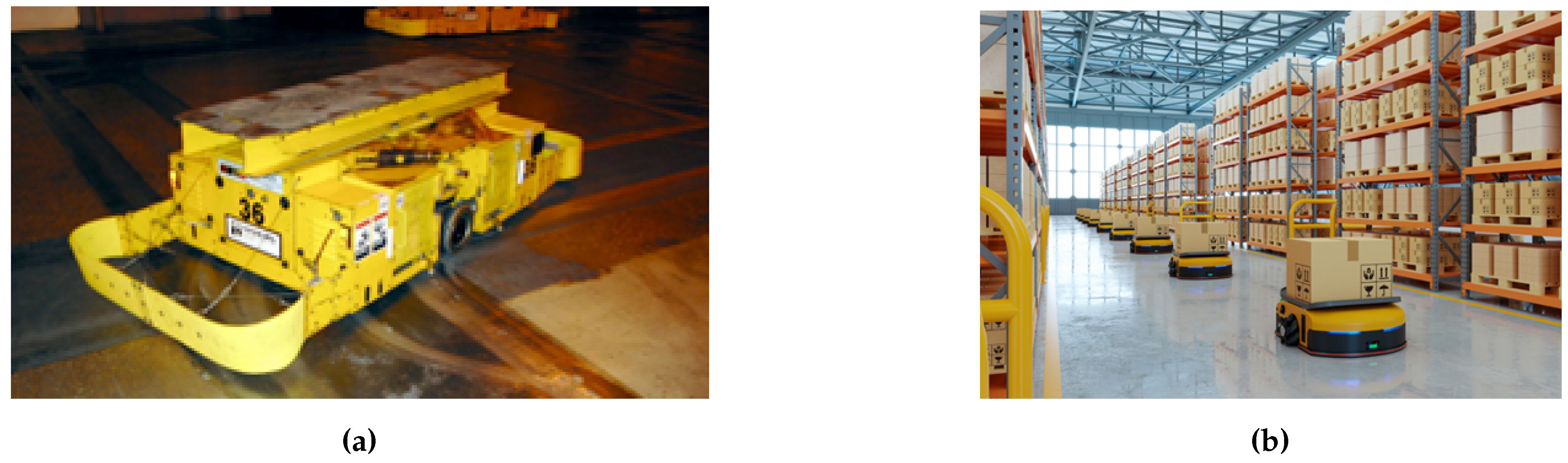
A fundamental perception platform commonly used for speed and separation monitoring is light detection and ranging sensors also known as LiDARs. LiDAR has been used to perform speed and separation monitoring for over a decade [12]. It is one of the earliest sensing approaches used in the field of SSM research. Prior to its applications in SSM, LiDAR had a rich development and application history. One of the earliest use cases for LiDARs and manipulator robots was in a 1980s Ford manufacturing plant. The LiDAR was used to help a manipulator robot pick and place an exhaust manifold out of a bin [13]. As the laser and receiver technology advanced, its packaging and power consumption decreased. Additionally, the computational power needed to process the sensing modality became more accessible. In the early 2000s commercially purchasable LiDARs came onto the scene via companies like Mitsubishi [13]. The LiDAR then began appearing in manufacturing plants to act as safety sensor guides for autonomous guided vehicles and robots (AGVs and AGRs). LiDARs also began to be paired with manipulator robots to perform collision avoidance. As the human robot collaboration field began to grow in the mid-late 2000s, LiDAR was quickly adopted as a baseline perception modality [12,14]. Not only was it used as the experimental sensor in SSM, LiDARs became the control perception modality to compare to a prototype distance sensor in question [15].
Figure 3.
(3a) Legacy AGV for manufacturing applications. (3b) More modern AGV product commonly seen in warehouse automation applications.
Figure 3.
(3a) Legacy AGV for manufacturing applications. (3b) More modern AGV product commonly seen in warehouse automation applications.
Through this rich development, LiDAR operating principles have greatly diversified. The initial laser ranging modality worked solely on the time-of-flight of a laser into the environment and back to the sensor. The light bounces off the environment and then returns to the aperture. As illustrated in equation 1, distance d to an object is half the speed of light c, times the time difference between signal transmission and receive, know as the time-of-flight or [14].
The multi dimensional 2-D and 3-D LiDARs take this distance measurement principle and apply it across a field of view (FOV) via mechanical or electrical means [13]. The laser transmits a pulse of light which reflects off a mirror. Then, through opto-mechanical means, the light is spread around the environment. The return light is received monostatically or bistatically and then digital signal processing is used to calculate the point cloud data and stream that information off to a PC or other external processing unit [13]. When transmission and receive is performed by a single aperture, this is considered a monostatic LiDAR. When the LiDAR has dedicated transmission and receive aperture, this is considered a bistatic LiDAR.
In general, LiDARs give detailed 3-D distance information about the environment. This detailed perception however comes at the cost of processing power, size, and power consumption. Different LiDAR topologies can balance some of these constraints out. Monostatic LiDARs are generally lighter than bistatic ones as there is one aperture for transmit and receive.
LiDAR has maintained a consistent presence in SSM Architectures through the history of SSM research [12,16,17,18,19,20,21,22,23,24,25,26,27]. [12] is an example of early research into SSM. In this work, a single 2-D scanning LiDAR was fixed, off-robot in the workspace. The LiDAR tracked human movement within the workspace. This data drove the Basic and Tri-Modal SSM experiments. Basic SSM commanded the robot velocity to zero if the minimum distance threshold was tripped, and Tri-Modal SSM which commanded a slower velocity state prior to a full safety rated monitored stop. [12] discussed the implications of the newly proposed ISO/TS 15066 standard at the time and indicated these initial findings showed promise for SSM in future HRC applications. Other SSM researchers continued to use this static off-robot LiDAR Tri-Modal SSM approach. [19] used this LiDAR configuration in conjunction with spherical estimation of the robot shape to compute a more accurate minimum distance between the robot and human. Other works have used LiDAR as a control to compare their experimental sensors against [28] or combined LiDAR into a fusion based sensor platform [25]. In [21], fusion is taken a step further by fusing multiple off-robot LiDARs with an on-robot ToF Camera to maximize sensor perception system coverage. Their algorithm aimed to have the local (on-robot) ToF Camera account for when the global (off-robot) LiDARs were occluded.
2.3. Time-of-Flight Sensors
The use of time-of-flight to determine distance spans a number of technologies. This includes laser range finders and LiDARs discussed in the previous section. Time-of-flight (ToF) Cameras evolved as technology innovations from these original sensing modalities. The distinction with ToF cameras are that unlike traditional LiDARs, ToF Cameras do not require mechanical components to rotate laser detectors [14]. Instead, this technology relies on the flood illumination of a laser or LED illuminator and some form of light sensor array. The sensor array can range from traditional complementary metal-oxide-semiconductor (CMOS) imagers and charge coupled devices CCDs, to Single Photon Avalanche Diodes or SPAD arrays [14]. The time-of-flight calculation for these devices is the same as Equation 1, but at a per pixel level. Sensor characterization tests have shown that ToF Cameras exhibit similar reflectivity, precision and accuracy performance to their LiDAR counterparts [29]. This makes them great alternative sensing candidates for LiDARs in existing SSM Architectures.
There are two major types of ToF Cameras. Each calculates distance in a different manner. One type is the pulsed-light camera which measures the "time-of-flight" directly. The structured light emitted by the illuminator goes out into the environment and then returns to the sensor. The light hits the sensor in the same pulsed pattern that it was transmitted in. Additionally, the start time of the light transmission is known. Therefore, the transmission to received time is a digital process to determine a time-of-flight and in turn, a distance to the target. The other major ToF Camera type used is called continuous-wave or CW [14,30]. This approach measures the time-of-flight indirectly. Instead of directly measuring the transmission to receive time, this method measures the phase shift of the modulated light pattern between transmission and reception [14]. The phase measurement is done by integrating small groups of pulses over time. The larger the integration time, the more detailed the return scene. However, longer integration times mean larger amounts of motion blur in a scene [14]. This motion blur can directly impact an SSM algorithm and or an object classifier.
Both camera types have their benefits and hindrances. For instance, the pulsed technique can be used to measure much further distances than the continuous wave approach. This hindrance on CW limits the top end of its measurement range to a maximum of 5 to 10 meters depending on the technology. However, in the context of SSM, the maximum range of desired perception is generally within a few meters. It is important to note that the maximum range is a relative term as the optical power of these cameras differ based on their system architecture. For instance, it is important to account for the inverse square law behavior of light [14]. The nature of the inverse square law diminishes the optical power of the camera’s illuminator rapidly as distance increases. Furthermore, when this phenomenon is extrapolated to a 2-D field of view, this means the optical power in the center will be significantly greater than the optical power at the edges. This phenomenon can be accommodated by diffusing the LED or laser illuminator in a structured manner.
Off-the-shelf illumination products build diffusers into the front of their lasers to provide a structured field of illumination (FOI) [14]. It is important to keep in mind that one must balance the desired imager FOV with the FOI illumination scheme. The balance between capturing the entire scene in a single wide camera may need to be balanced with multiple smaller FOV ToF cameras that can capture narrower point clouds at a further distance [31].
As previously mentioned, coverage of the workspace is important to keep in mind, as blind spots in the perception system can pose risks to the human operating in the collaborative workspace [32]. The overall performance of these ToF cameras can generate 15 - 450 frames per second (FPS) depending on the camera architecture. The frame rate is a crucial aspect of SSM as the monitoring system chosen for the workspace should aim to be ≥ 33 Hz for robot speeds of 1.0 m/s. At this refresh rate, a robot traveling at 1.0 m/s can cover 60 cm in one sample cycle [22]. Too slow of an FPS and the SSM algorithm will not be able to adjust the robot trajectory or velocity in time to avoid a collision with a human or object in the workspace. Therefore, it is imperative that robot operating speed is matched to the FPS capability of the sensors being used. These ToF cameras come in a wide variety of FOVs, resolutions, frame rates, and depth ranges. It is also important to note that these properties will also impact the power consumption of these units as well. At the high resolution end of the ToF technology is the Azure Kinect Development Kit seen in Figure 4 [31]. This product can capture 3-D point clouds in both narrow and wide field of view modes. The Azure for Kinect DK is the updated version of Microsoft’s previous Xbox Kinect and Kinect V2, which each are extensively used in SSM research [33,34,35,36,37,38,39,40,41,42,43,44,45,46]. Additionally, there is base software support for RGB depth overlays since the module includes both a ToF camera and RGB camera. The sensor exhibits a refresh rate that ranges from 10 to 30 FPS depending if the camera is operating in megapixel or quarter-megpixel mode.
At the lower cost and performance end of the spectrum is the STMicroelectronics VL53L1x time-of-flight sensor seen in Figure 5. Though this device only has a 16x16 SPAD array resolution, it has a sample rate of 50 FPS at 1 m and 30 FPS at 4 m. These devices are low cost and easy to integrate into an on-robot SSM application. A number of works rely on this sensor as the perception component of their SSM Architecture [28,32,47,48,49,50,51,52,53,54].
The benefits of ToF technology in the SSM setting is that it provides the same kind of direct distance measurement that a LiDAR can produce at a much cheaper price point. Additionally, the size and power constraints of ToF cameras and sensors are much lower than their LiDAR counterparts. This provides an opportunity for ToF sensors and cameras to be integrated into both on-robot and off-robot reference frames to generate a holistic point cloud of the entire collaborative workspace.
2.4. Radar Sensors
In addition to light based perception, electromagnetic waves specifically in the radio frequency RF range (greater than 60 GHz) can be used to detect objects and targets in a scene[55]. These radar sensors which operate in a mode called frequency modulated continuous wave or FMCW can be used to determine a number of spatial elements in one reading. These sensors transmit RF waves out across a linear spectrum of frequencies in what is called a chirp configuration [55]. This chirp bounces off the environment and is received by the receive antenna on the radar. The raw received signal is then passed through a Fast Fourier Transform or FFT to then decode the spatial data from the signal [55]. Depending on the number of transmitters and receivers, these radar sensors have the ability to determine the distance, velocity, and angle between the object and radar [55]. The distance from a single object only requires a single transmitter and receiver. The relationship between distance, frequency, phase, and wavelength is demonstrated in equation 2 [55].
When the chirp is transmitted and then returned with an object in the field of view of the radar, there will be a frequency difference between the transmitted and returned chirp. After the receive signal is passed through an FFT the single object will be expressed as a phase difference of constant frequency. This frequency is then extracted and passed through equation 3 to determine the distance to the target.
In the event multiple objects are detected, the FFT will express multiple constant frequency components [55]. This return behavior can be thought of as the "point cloud" perceived by the radar. Multiple transmitters are needed in order to measure the velocity of objects in an environment. By sending two chirps distinctly spaced in time, the returned signals will have the same frequency components but different phases. The velocity of the object can be determined by passing the phase difference through equation 4.
Multiple chirps and a second FFT is required in order to measure multiple object velocities in the field of view. The signals returned will have different frequency components and phases. The signals must be passed through an FFT a second time, also known as a Doppler FFT, to then distinguish the phase differences for each frequency component or object [55]. Measuring angle requires the inverse architecture of measuring velocity. Angle measurements require two transmitters and a single receiver [55]. The distance between the two receive antennas will be a known separation distance. The angle computation is performed by sending a chip transmission, waiting for the signal to be received by the receive antenna, and then taking the phase difference of the two return signals between the receive antennas. The known antenna separation and phase difference are then used to compute the Angle of Arrival or AoA in equation 5. The estimated AoA using equation 5 is most accurate near 0 degrees and least accurate near the maximum angle.
Different design parameters impact different performance metrics of these radar sensors. The separation distance between the receive antennas has a performance impact on the maximum angular field of view defined by equation 6. A ± 90 or 180 total FOV is achieved when the received antenna separation distance is half the signal wavelength [55].
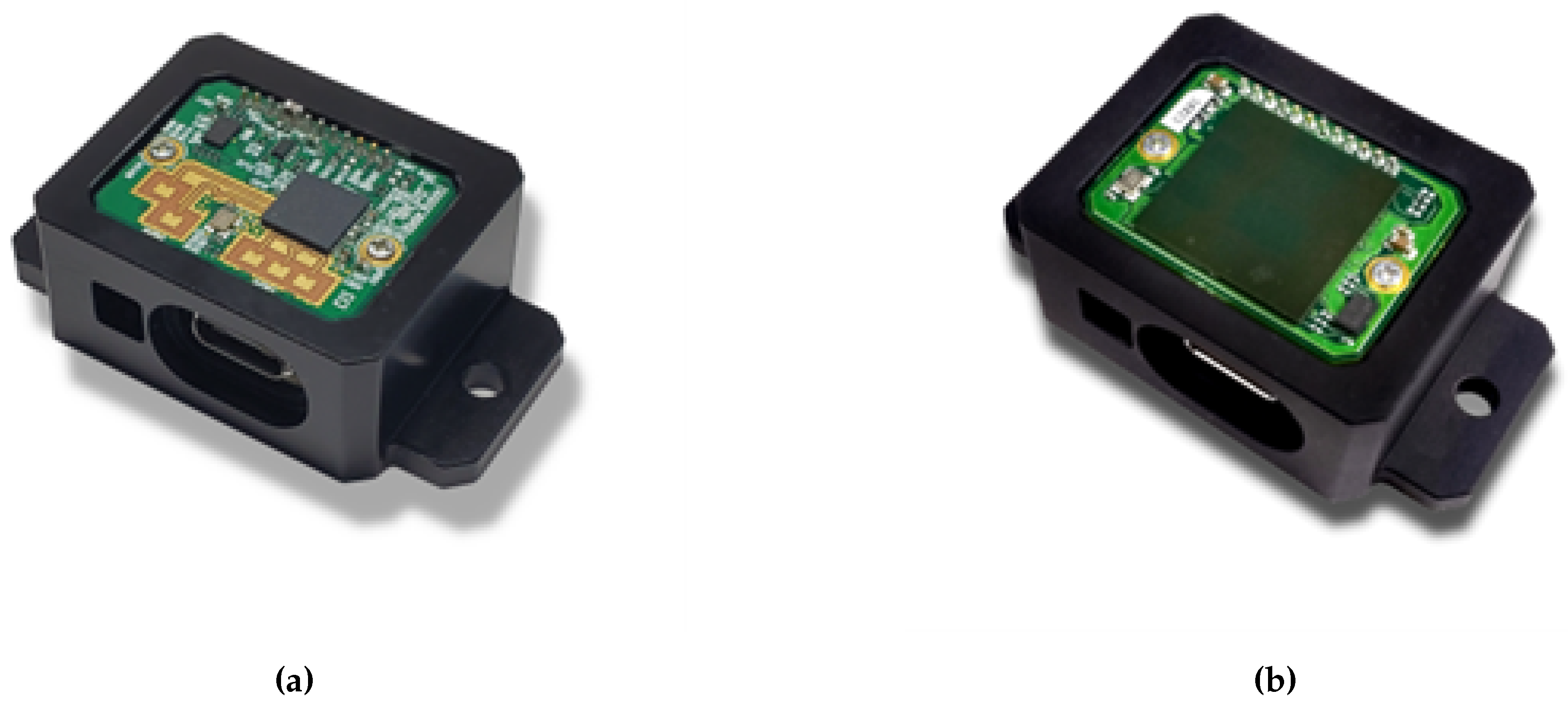
Additionally, the number of frequencies within a chirp pattern impacts the frequency resolution which is a similar parameter to point cloud density. Furthermore, the computational front end device impacts the quality of chirp transmission, return, and computation. A number of silicon manufacturers have made Application Specific Integrated Circuits, or ASICs, for radar sensor signal processing. Texas Instruments has a mature product line of mmWave radar sensors [56]. The product line name denotes the wavelength of the transmitted and returned signals produced by their sensors. The mmWave ICs combine the chirp generation, return signal filtering, sampling, and frequency domain processing. These radar ICs are developed into multiple tx and rx antenna structures. The antennas can be routed onto the printed circuit board near the chip or even on the chip itself which is called the antenna on package or AoP mmWave sensor [57]. With the multiple tx and rx antenna structure, these sensors can determine the position, velocity, and orientation (AoA) of multiple targets in a single frame capture. This variable frame rate can be anywhere from 1 - 30 FPS.
Figure 6.
(6a) External Antenna mmWave Base Radar Product [58]. (6b) Antenna on package mmWave Base Radar Product [58].
Though the "point cloud" returns from these devices will not be as rich as their LiDAR counterparts, they have some robustness and other performance qualities that LiDARs can struggle to overcome or achieve. For instance, LiDARs are a light based sensing modality, meaning environmental obstructions like fog, smoke, or mist, will impact the point cloud distance accuracy as these mediums will refract some of the LiDAR transmission signal. Radar innately will not be impacted by these kinds of mediums due to the innate nature of the sensing modality. Furthermore, radar has the ability to transmit through a number of solid materials as well including plastics, glass, and soil. Radar sensors will also require less computational power and energy to make spatial measurement when compared with a LiDAR sensor [15]. Lastly, one key performance feature is mmWave sensors have been tuned to detect living objects within a sensor’s FOV [59]. Living object detection has a number of key applications in the automotive and industrial spaces for safety. In cabin radar on cars and industrial vehicles can determine the presence of a human and even their heart and breathing rate. Additionally, in automotive applications, these sensors can help prevent the child left behind phenomenon, where children are accidentally left in a car during extreme heat or cold leading to accidental death [59]. In the world of HRC, this key feature has the potential to be used to locate a worker and measure their biometircs while operating in the hybrid workspace. With these given characteristics, researchers have been applying radar in automotive and industrial applications well into the last decade. In robotics, LFMCW radar has been used in collision avoidance applications [60,61]. Specific to HRC research, radar has been used for fence-less machine guarding and target tracking for speed and separation monitoring [15,17,18,25,60,62,63].
2.5. Vision Sensors
Vision-based perception modules rely on a fundamental light-based sensing element. The sensors may be configured as stereoscopic cameras in order to compute a depth or operate as an independent visible imager to classify and segment scene data for fusion with LiDAR, ToF, or Radar.
2.5.1. Stereo Vision
Stereo vision has been used in computer vision and robotics since that late 1990s [64]. The fundamental principle of stereo vision is the merging of two visible imager based frames with known separation and orientation to compute a 3-D depth from the cameras. Stereo cameras, like the Intel RealSense in Figure 7, can operate on passive light in the environment and have active illumination incorporated into the sensor to provide more controlled light for a scene. Stereo cameras have a number of benefits for performing 3-D depth computation.
For instance, this perception modality is based on traditional CMOS or CCD imagers which can operate at significantly higher frame rates than ToF Cameras or LiDARs. These sensors can easily achieve 60, 90, or even 120 FPS. Furthermore, the imagers selected for these perception modules tend to be global shutter imagers as opposed to rolling shutter. This design decision makes these systems less prone to motion blur in a scene. The depth range of these sensors tend to reach out a few meters and can sense as close as 0.3 meters [65]. This range is highly suited for SSM and other HRC applications.
Along with beneficial traits, there are other key performance factors that can hinder stereo vision for HRC applications. One key issue with stereo vision is its inability to compute depth on texture-less surfaces and objects. Stereo vision struggles to compute depth on walls, ceilings or floors, which could be used as computation references in some applications. However, in HRC applications, the main focus is to compute the distance from the robot to a human. Humans are highly textured targets in most cases due to their shape and the texture of their clothing or uniform. Due to the nature of high FPS multi-megapixel image sensors used in stereo cameras, a significant amount of data must be processed in order to generate a point cloud. Again, this hindrance has becomes less of an obstacle as processing platforms have increased compute power and dedicated cores for image processing and hardware acceleration. Within the field of SSM, the first applications of stereo vision were seen in 2011 [66]. In [66], data from three cameras were fused to determine the location of a human in a collaborative workspace. The worker in this experiment wore special clothing with colorized markers to aid in computation of body position. Stereo was also used many times in conjunction with other perception modalities like ToF [67]. In this work, the ToF point cloud and stereo frame were fused into a single data frame. Over time, the FPS of the sensors increased, and the capabilities of the processors and computational platforms increased as well. This allowed for point cloud computation in conjunction with human pose estimation. These works apply the stereo perception method in both on and off-robot mounting strategies [12,20,21,26,35,36,66,67,68,69,70,71,72,73,74,75].
2.5.2. Mono Vision
With the introduction of embedded system platforms with hardware acceleration, machine vision and machine learning, vision based depth processing has significantly improved. Instead of dual cameras for stereo based depth, monocular based depth estimation has become accurate enough to estimate the point cloud of a human in a scene with just one imager. In [76], a single RGB camera stream is fed to an NVIDIA Jetson TX2 which contained a convolutional encoder-decoder network which preformed segmentation and depth estimation of humans within the camera frame. The monocular depth estimation approach is a newer method that requires lower sensor power, but more computational power as a trade-off. The rise in performance of monocular based depth estimation algorithms present a strong opportunity for these models to start being applied in SSM Architectures.
The traditional application of RGB imagers in HRC and SSM are for tracking segmentation and pose of a human in a fused sensor frame if one has the computational bandwidth for additional sensors on their platform. The human can be classified in the RGB frame, then the overlapping pixels in that frame are cross-correlated and segmented out of the LiDAR, ToF, or stereo vision depth frame [24,25,26,34,35,70,73,76,77,78,79].
2.6. Thermal Vision
One modality that has a key characteristic for identifying humans within a scene is thermal imagery. Thermal-based perception modules rely on a fundamental temperature-based sensing element. Thermal imager development dates back to the 1960s for a number of scientific and military applications. These sensors could monitor the thermal profile of the surface of the earth, or monitor geological zones with higher thermal activity. Overtime, thermal imaging innovations began to scale down the size of the sensors, and the technology found its way into the commercial sector via companies like FLIR. Two major thermal imagery modalities that are commonly used are micro-bolometers and thermopiles. Thermopiles measure thermal response using the same mechanics as thermocouples. These element of dislike metals generate a voltage based on the temperature detected by the device. These devices are grouped together to create sensors that generate a thermal image like the TeraRanger Evo in Figure 8 [80]. Microbolometers on the other hand, are sensors made up of hundreds of silicon constructed thermistors. The thermal sensing mechanic of a thermistor is its resistance. As the detected temperature changes, the resistance of the sensing element changes [81].
In most industrial applications, humans are warm compared to the average temperature in an industrial environment. This generally makes humans appear as a clear feature in a thermally sensed frame of an industrial environment. A number of researchers have taken advantage of this modality to couple with other perception methods like ToF and stereo vision to map the human thermal signature to the depth point cloud [35,36,71,82]. In [36], an IR stereo camera data is fused with 360IR imager data to track humans in a collaborative workspace. In [83], Terabee Evo Thermal sensors were used to relate human temperature to distance directly. The temperature reading of the human would decrease as the separation distance increased. Another thermal fusion application was done in [35], where the authors fused stereo, ToF, and Thermal data to train their depth estimation and human classification model. The thermal imager used in [35] was the Optris PI 450i thermal camera which had a 382 x 288 pixel resolution and 80 Hz refresh rate [84]. It is important to consider performance and cost metrics of these different thermal modalities and devices. The sensor used in [82] is a thermopile based sensor, therefore, the refresh rate or sensor frames per second is much lower than other papers which used thermographic cameras or micro-bolometers. The trade with these higher performance imagers is that they cost significantly more than the thermopile devices. The Optris PI 450i in Figure 9 retails at at $6,300 USD [84] whereas the TeraBEE TeraRanger Evo Thermal sensor retails for under $100.00 USD [80].
3. Speed and Separation Monitoring Architecture
Each HRC method has implementation and integration trade-offs in research and industry. However, advancements in perception and computation technologies has begun to soften the trades against SSM. These new technologies open the possibilities to lower cost, power, and complexity of SSM Architectures; while at the same time, increasing computational performance, sensor coverage, and data throughput. Figure 10 illustrates the high-level architecture of an SSM Architecture. The perception sensing, computational units, and system requirements of this architecture are the major focus points of this work. This section details the trades and considerations one must make when constructing a SSM Architecture. The perception system mounting, perception sensor performance, system calibration requirements, and architecture computation approach must be well matched to the particular use case or experiment.
3.1. Perception System Mounting
As defined in the previous section, SSM requires perception systems on-robot or off-robot in order to monitor the speed and separation between the robot and the human. There are significant benefits and considerations when choosing a robot mounting strategy.
3.1.1. Off-Robot
Off-robot systems do not need to consider complex mounting techniques to keep the sensors in place on a moving manipulator arm. The sensor systems usually consist of point rich sensors like LiDARs, stereo cameras, ToF cameras, or radar [15,25,61,69]. The off-robot approach also generally provides better sensor coverage and minimizes the chance for occlusions or spatial regions where the perception system is blind. These blind spots can be caused by a particular robot position, human position, or other environmental obstruction. On the other hand, off-robot sensing has very low flexibility from a calibration perspective. Off-robot perception systems must be calibrated such that the robot and perception reference frames are matched to the world frame. This is key for computing the actual minimum distance and velocity between the human and the robot. Once the robot is moved within the environment, or one of the sensors are adjusted, the entire system needs to be re-calibrated.
3.1.2. On-Robot
On-robot sensing however, has significantly more flexibility when it comes to robot placement in a collaborative environment. Assuming solid fixturing of on-robot sensors, the position of the robot in the workspace does not impact the spatial transforms from the perception system to the robot. This greatly reduces the calibration complexity of on-robot systems. However, like off-robot sensing, there are still compromises and considerations. On-robot perception systems are much more prone to spatial occlusions and blind spots. The robot arm can easily move in front of the perception system and cast a shadow or block line of sight with the human making minimum distance and velocity calculations impossible. Additionally, in earlier years of SSM research, the size of point rich sensors made them challenging to use in on-robot perception approaches. Therefore, many researchers resorted to lower resolution sensors like Infrared (IR) distance sensors, or 1-D ToF sensors [11,47,49,85].
3.2. Perception Sensor Performance
The perception technology selection for an SSM Architecture drives the observably of the workspace while the SSM algorithm is executing. The are many dimensions to sensor performance when building the perception system. As previously mentioned, sample rate, resolution, coverage, calibration, and physical mounting all play a role in architecture performance.
3.2.1. Sample Rate
The sample rate or, frame rate, of a particular sensor will limit the refresh rate of the minimum distance calculation. A depth sensor of 60 FPS, provides twice as much data as a depth sensor that only provides 30 FPS. Without the consideration of the other architecture requirements or computation loop speed, the sensor sample rate is the fastest rate in which the SSM algorithm can recalculate the minimum distance. As previously mentioned, the maximum velocity the robot can operate is driven directly by frame rate. A 33 FPS sensor would be able to detect up to 3 cm of moment if a robot was traveling at 1 . Increasing robot movement without matching frame rate creates larger losses of potential motion. In addition to influencing algorithm loop frequency, sensor sample rate plays a role into the bandwidth for filtration of the distance data. An example for this is the use of a windowed averaging filter to soften noisiness or the standard deviation of distance data. At a minimum, a window filter needs to compare two received data points together to generate and averaged output. Therefore, the larger the filter window, the more input data points required to generate a single filtered data point at the output. Low frame rate sensors (10 - 15 FPS) significantly limits filtering options where as higher frame rate sensors (60 - 100 FPS) open up the amount of filtering bandwidth without jeopardizing the SSM algorithm loop time significantly.
3.2.2. Resolution
Sensor resolution is another key requirement for good SSM Architecture performance. The particular resolution in question for SSM Architectures is the resolution of distance measurements. Sensor resolution directly impacts SSM algorithm granularity. In other words, the range and transition between danger states becomes much coarser when the selected sensor modality has limited resolution. In addition to depth granularity, resolution directly impacts velocity calculations. A 1.0 cm resolution depth sensor will always compute a higher minimum velocity than a 1.0 mm resolution depth sensor. The velocity computation via change in distance will inherently be no less than 1.0 cm/s vs 1.0 mm/s in turn rising the possibility of entering a protective stop sooner than necessary increasing down time. Also, from a safety perspective a lower resolution sensor will provide a lower number of changing distance points when the robot and human are on a path to collide. Depending on the velocity of the trajectory, a higher resolution depth sensor will provide more transitioning distance points to the SSM algorithm increasing the likelihood the SSM algorithm could lower the robot velocity before a collision occurs.
3.2.3. Coverage
The aim of sensor coverage in an SSM Architecture is to minimize system blind spots. Any region in which the perception system cannot see the human or calculate the minimum distance poses a risk for collisions. Coverage is heavily influenced by the FOV achievable by the sensors in the architecture. In [48], the sensors selected for on-robot sensing had a 25 degree FOV. Therefore, it was understood that the 8 ring sensor approach contained blind spots within a meter of the sensor ring. During experimentation however, it was found that the blind spots were acceptable for the particular experiments conducted in [48]. In general, the larger FOV sensors make high workspace coverage less challenging. Less individual sensors can be used in comparison to lower FOV solutions in turn lowering the number of sensors a computational platform may need to communicate with. However, larger coverage generally means more data collected for computation. Therefore, balancing coverage requirements with computational bandwidth must be done on a case by case basis.
3.2.4. Calibration
The accuracy and precision of the computed minimum distance is significantly influence by how the SSM Architecture is calibrated. Even if high performing sensors are used in an SSM Architecture (high resolution, FOV, FPS, and ect.) the system will perform poorly without proper calibration. On or off-robot, it is crucial that the physical location of a sensor in an SSM Architecture is mapped accurately to the virtual world frame. The calibration process varies depending on the sensor modality used. Vision based sensors benefit from Hand-Eye calibration tool kits [86]. The approach in [86], meshes images captured from a sensor looking at a checkerboard with the particular robot pose during image capture. The data is then pushed into a solver to generate the frame transformation matrix between the sensor frame and world frame. Other non traditional imager based systems like LiDARs and radars must use different techniques for sensor to world frame calibration. One technique that is used for LiDARs is physical mapping of the LiDAR position in a motion capture system [29]. In [29], retro reflective markers were placed on the base of the LiDAR module to form a rigid body in the motion capture software. The coordinates and orientation of the rigid body center was published from the motion capture software. The rigid body center was then used to construct a transform from the LiDAR to the robot end effector. The calibration of radar can also be done using motion capture but also another target based approach. In [60], the radar sensors in the SSM workspace were calibrated using a corner reflector to generate a high signal to noise (SNR) target for the sensors. Two calibration techniques were explored in this work. One took advantage of the forward kinematics of the robot in the workspace and uniform fixturing to make an estimated transform from the robot TCP to the sensing point on the radar. [60] also explored using singular value decomposition (SVD) on multiple radars point at the same corner reflector to perform point cloud alignment. It is important to consider the calibration complexity of a particular perception modality before integrating it into and SSM Architecture. As previously mentioned, if a complex calibration technique is required for an off-robot sensor scheme, any time the robot or sensor is moved within the workspace, the calibration process must be performed again to guarantee accurate operation of the SSM Architecture.
The selection, mounting, and calibration of perception sensors are key factors when building up an SSM Architecture. However, the computational platform also plays a key role as it will be responsible for processing the perception sensor data and running the SSM algorithm itself. There is a range of options that can perform this role and choosing the best fitted one involves balancing processing capabilities, power consumption, space claim, and interface compatibility.
3.3. Computation
As depicted in Figure 10, data processing and SSM algorithm execution are the key computational loads in an SSM system. Sensor data must be captured, sometimes filtered, and then fed into an SSM algorithm. In turn, the algorithm outputs a command or coefficient which then updates the robot behavior via a change in speed, trajectory, or fully halting the robot into a safety rated monitored stop. Many early SSM Architectures relied solely on PCs for data processing and algorithm execution. In some cases, there were PCs dedicated to sensor data processing while the other would be used to run the algorithm in conjunction with a digital twin [16,61,87]. Digital twin introductions into SSM Architectures became more prevalent as the processing power of GPUs and PCs increased over the years. These virtual models encompassed the robot and all sensors into a single calibrated world frame. The real sensor data interacts with the virtual robot and is used to help the real robot distinguish between self colliding sensor data and true on human data points [48]. As architecture complexity advanced in the field of SSM, more sensors were combined into single digital twin ecosystems to significantly reduce workspace occlusions, which present one of the largest challenges for SSM Architectures. As years passed, data capture and processing has started to be offloaded from purely PC based computational platforms to microprocessor and microcontrollers [47,49,51,53,77,88]. These peripheral integrated processors like the STM32 in Figure 11 may run a simple baremetal loop or full Real Time operating systems (RTOS). The primary objective is sensor data capture, filtration, and publishing to the central PC to act as the SSM algorithm input. This approach is widely used with the more cost effective 1-D ToF sensors, thermopiles, and lower resolution sensors previously discussed.
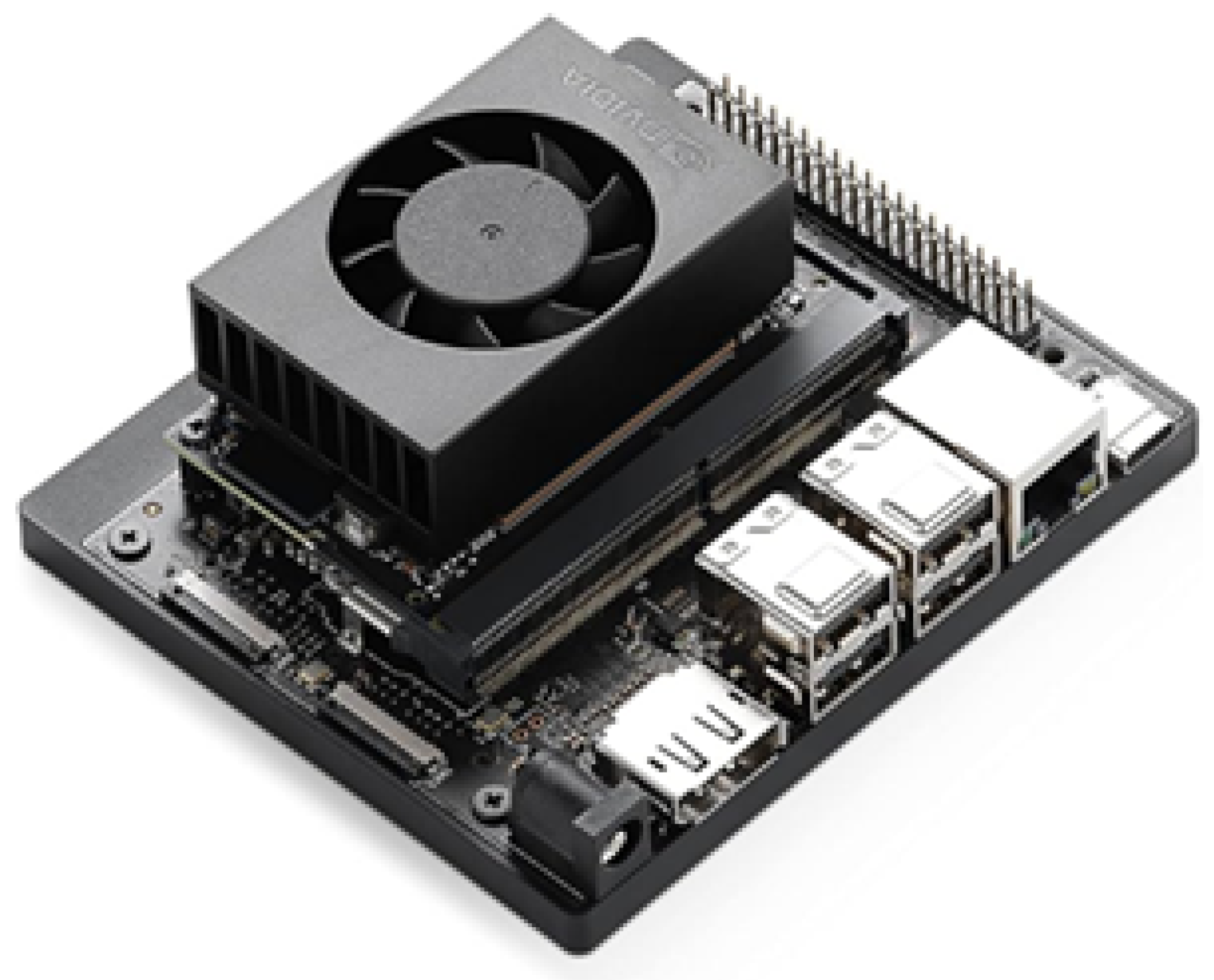
In the most recent years, a new type of processing platform has entered the field of SSM research. Embedded System modules have begun to be integrated into SSM Architectures. These modules include devices like the raspberry pi, NVIDIA Jetson Orin, and the Intel NUC. The power of these systems on module (SOMs), system on a chip (SOC), and single board computers (SBCs) are their ability to provide bare metal peripheral interfaces while also supplying significantly more processing power than a traditional microcontroller or microprocessor. These devices contain processing cores, hardware accelerators, on board memory, and gigabit connectivity interfaces like PCIe and Ethernet. In SSM Architectures, these edge units have typically been used to offload point rich sensor processing from the main algorithm PC in an SSM Architecture or reduce the number of full PCs in more complex multi point rich sensor systems [15,17,23,25,37,76,77]. With AI at the Edge catching momentum industry and research fields, these embedded platforms have started to not only record, and process data, but also use AI to extract key features and even provide refined speed and separation data directly to the PC running the SSM algorithms.
Figure 12.
NVIDIA Jetson Orin Starter Kit for platform evaluation.
4. Materials and Methods
The collection of peer-reviewed papers surveyed in this work span nearly three decades of general robotics perception research (1996 - 2024) and around a decade of papers that specifically focus on SSM (2008 - 2024). Although sensor and computational citations are noted in the reference section, only SSM experiment conference papers and journal articles are included in the results section data set. Source gathering for this work spanned a two-year period (2022 - 2024). The articles were found through peer reviewed research databases including IEEE Xplorer, ASME, Elselvier, ScienceDirect, Wiley Online Library, ProQuest, SpringerLink, Frontiers, MDPI, and the Journal of Open Source Software. The citations were imported into a Zotero collection and tagged according to their relevance to SSM research and the construction of an SSM Architecture in the published experiments. Figure 13, illustrates the workflow for collecting citations and tagging data. The exported and tagged citation set, along with processing scripts and figures can be found publicly available at [89].
In order to expand the sample size of the works in the survey, an initially smaller collection of works was uploaded to Inciteful [90]. This tool looks at the connections and relevance between papers based on cross-citations found within an uploaded group of works. It was found that 50 of the works in the collection were connected citations. The web of connections in Figure 14 illustrates the connections between papers from dozens of authors. From this network of connections, the tool then provided additional works of relevance related to the uploaded group of works. The approach found 13 additional sources that were added to the pool of works in this survey dataset. All sources came from the databases mentioned above and listed in Figure 13.
The works were analyzed to determine the perception methods and computational devices used in the proposed SSM experiments. Each paper was manually tagged with one or several of the labels defined in Figure 13. The works used a range from one perception method to multiple sensor modalities fused together. If an architecture integrated stereoscopic cameras and LiDAR in the SSM experiments, then the work was given both the LiDAR tag and the Stereovision tag. The same logic was used for the computational platforms observed across the works. If a experiment required a microcontroller for data processing and the actual SSM algorithm was executed on a PC, then the work was given both the Baremetal tag and the PC tag.
Once all peer reviewed works were tagged within the Zotero citation group, the citation dataset was exported as an Excel file for processing. The data columns of interest consisted of Publication Year, Author, Title, and Manual Tags. Each citation (row) was then searched and incremented through to account for each tag used in the manual tag cell of that given citation. The tag counts per citation were then summed together with all citations in the dataset per a given publication year. This general categorization is the foundation for all figures presented in the results section of this work.
5. Current Trends and Limitations of SSM
Figure 15 depicts the overall spread of perception modalities and computational platforms found within the citation dataset. These graphs demonstrate the general spread seen through the papers without temporal context. In the remaining sections, the data will be correlated with the publication dates these experiments were run to show trends with respect to the utilization of these different sensors and computational platforms in SSM experiments.
5.1. Perception Trends
Sensor modalities were tagged and divided into six categories. Per Figure 16, categories were 1DTOF, 3DTOF, LiDAR, Radar, Stereovision, and Monovision. It was observed that LiDAR and vision based systems were present across the years compared to the other categories. Radar and ToF modalities only started to show heightened prevalence in 2018. Additionally, it was observed that though LiDAR maintained some integration into SSM Architectures, there has been a substantial rise in Monovision, Stereovision, and ToF based approaches in the past four years.
These sensor trends correlate significantly with the popularity of sensors used in the field over a given period of time. The Kinect and Kinect V2 could be easily integrated into ROS and were relatively cost effective compared to multi thousand dollar LiDARs and other advanced vision systems. This may contribute to the higher values of ToF and vision based approaches in this field illustrated in Figure 17. 2018 onward however, has seen a rise in vision based methods. Both stereo vision and single imager based systems have been aided by increased computational abilities and development of easily integrable AI estimation algorithm on these embedded platforms.
5.2. Computational Trends
In addition to tagging sensing approaches, each work in this survey collection was tagged for computational products used in the SSM Architectures presented. Eight specific platform in model types were identified and labeled within the citation dataset. In Figure 18, the eight categories were generalized to PC, Baremetal, and Embedded platforms. If a work used multiple computational devices, then that work received multiple computational citation tags. Overall, PCs were the foundational platform used for SSM Architectures. Then, as seen in Figure 19, there was a significant rise in the number of architectures which integrated microcontrollers from 2018 to 2019. Many of these tags were associated with work researching cost effective SSM Architectures that used lower resolution depth sensor technology including 1-D ToF and thermopiles. Lastly, over the past 3 years, (2021 - 2024) there has been an observed uptick in the use of embedded platforms in SSM Architectures. May of these embedded platforms were integrated with point rich sensing modalities like stereovision, ToF, and radar.
Table 1 is a highlight of key works in the SSM Architecture Citation dataset. These works present foundational experiments or exhibit new innovative approaches for structuring an SSM Architecture. Foundational experiments include work that helped define SSM approaches or were one of the first instances to use a particular sensing modality. Innovative approaches include experiments which fused multiple sensing modalities or computational platforms in a unique or innovative manner.
5.3. Scope Limitations
The works collected in the Current Trends section were selected by hand. The selection of a particular sensing or computational tag for a work in this data-set was performed manually. There are likely many different SSM Architecture configurations in research that were not captured in this smaller sample size. However, due to the manual approach, the small dataset contains only clear examples of well constructed SSM Architectures.
5.4. Technical Limitations
Key technical advancements play a major role in gating technology trends within SSM research. The rise of particular technology usage in SSM Architectures is gated by the development of said technologies. It is important not to over interpret the prevalence of I2C ToF distance Sensors right as they were brought to market in the mid 2010s. The key to identifying their impact on the field is their continued presence in papers the five years following their introduction. Embedded System Modules have seen a large rise in usage over the past few years, however this does not guarantee they are a perfect fit for SSM Architectures.
6. Discussion and Conclusion
Overall, research in SSM and the evolution of SSM Architectures has been highly active over the past decade. The perception and computational systems in these architectures have significantly increased in complexity, performance, and flexibility. LiDAR based perception and PC based computation laid the foundational groundwork for SSM Architectures. With the rise of the Kinect and ToF technology as a whole, an observable shift towards off robot ToF sensing was seen in the mid 2010s. With continued silicon manufacturing improvements and AI development, the late 2010s and early 2020s has demonstrated a continued shift towards using point rich sensors (3-D ToF, Stereo/Mono Vision, Radar) in conjunction with embedded system platforms.
From the computational and perception trends, what is clear is that the SSM Architectures must be tailored to the particular SSM use cases. Point rich sensors like ToF and Stereo vision are great sensor modalities where computational limitations are less, the robot maximum velocity is near 1, in turn setting your FPS requirement to around 30 FPS. Currently, most image and light-based sensor options can easily achiever near 30 FPS. If the selected perception method requires filtering, then more FPS is recommended. Radar within SSM Architectures show promise when mounted statically off-robot or on the robot base. They will not provide the same coverage as LiDAR, but will cost less, and are not dependent on the same light based mechanics as LiDAR, Stereo vision, or ToF. Hence, radar makes well as a sensor fusion companion to visible perception nodes in an SSM Architecture. As for computation, if the research focus is on processing power and higher level collision avoidance control, PCs still provide the highest ceiling of processing power. In the event that the SSM use case or research is focused more around deployment flexibility, cost reduction, or simple to calibrate sensor modalities, then baremetal processors would work well for sensor input to serialize data for a PC to control the SSM algorithm itself. However, the counter approach would be to consider using an embedded System Module for sensing and control if the end collision avoidance is only Tri-Modal.
The significant gap that remains in this field is the movement of the SSM algorithms, digital twins, and ROS master nodes directly into the embedded system modules. Each year, embedded platforms have seen large performance boosts due to the demand for AI at the edge in the automotive and industrial sectors. These platforms have reached a point where they can reasonably be used to not only process depth and feature data, but also run the full SSM algorithm and produce the updated trajectory commands to the robots. In [76], experiments around a monocular depth estimation algorithms were performed across a number of platforms. One of the platforms tested in the experiments was the NVIDIA Jetson Nano. The Jetson Nano is the lower power cost effective SOC in the NVIDIA Jetson Product line. Though these experiments were focused on general depth estimation of humans, it illustrates the potential for these lower power SOCs to provide purely monovision based point clouds into an SSM Architecture application. The Nano provided lower frame rates than its PC counterparts in the benchmark tests, but demonstrated the potential for optimization through TensorRT to provide a 114 FPS data stream.
These embedded system platforms, like the Jetson Nano, are physically much smaller than mid or even mini ATX based PCs. Therefore, there is an opportunity to gain more space claim back in the collaborative workspaces and SSM Architectures. Additionally, PCs consume hundreds of watts of power compared to the tens of watts required by embedded platforms. Also, traditional higher processing capable PCs can cost thousands of dollars, whereas a lower profile Linux SOM, though less feature rich, is considerably more affordable. Furthermore, the compactness of these devices also allow for less complex mechanical integration. There are opportunities for these devices to be directly mounted onto the robot. This opens the potential for the entire SSM Architecture to move with the robot in the collaborative workspace, greatly increasing the system flexibility of deployment. A shift towards a purely embedded system approach for SSM Architectures could potentially decrease the physical space claim of the system, lower power requirements, lower system cost, while maintaining system performance, and increase workspace flexibility if there is a desire to reconfigure the SSM Architecture.
More experimentation with point-rich perception sensors and embedded system modules is required to validate their fit for SSM Architectures and use cases. It will be important to understand the balance of intended maximum velocities of human and robot motions in particular SSM application. It should be investigated if metrics like max velocity, robot work envelope, human work envelope, and collaboration overlap could be used to output the perception and computational modality requirements for an SSM Architecture. This way that architecture scheme would be optimized for that particular SSM use case.
Author Contributions
The Contributor Roles Taxonomy per CRediT taxonomy is as follows. Conceptualization was performed by O.A.; Formal analysis was done by O.A.; Funding acquisition was acquired by F.S.; Investigation was done by O.A., S.A., and K.S.; Methodology was constructed by O.A. and K.S.; Project administration was managed by F.S.; Resources were provided by F.S.; Software was implemented by K.S.; Supervision was done by F.S.; Validation was performed by K.S. and S.A.; Visualization was prepared by K.S. and O.A.; Writing - original draft was done by O.A.; Writing review and editing was done by S.A.
Funding
This material is based upon work supported by the National Science Foundation under Award No. DGE-2125362. Any opinions, findings, and conclusions or recommendations expressed in this material are those of the author(s) and do not necessarily reflect the views of the National Science Foundation.
Institutional Review Board Statement
Not applicable to this study for no humans or animals where involved.
Data Availability Statement
The original data presented in the study are openly available in survey_SSM_robotics, GitHub at https://github.com/kxs8997/survey_SSM_robotics/tree/main.
Conflicts of Interest
The authors declare no conflicts of interest.The funders had no role in the design of the study; in the collection, analyses, or interpretation of data; in the writing of the manuscript; or in the decision to publish the results.
Abbreviations
The following abbreviations are used in this manuscript:
| MDPI | Multidisciplinary Digital Publishing Institute |
| SSM | Speed and Separation Monitoring |
| PFL | Power and Force Limiting |
| ISO | International Organization of Standardization |
| ToF | time-of-flight |
| IR | Infrared |
| HRC | Human Robot Collaboration |
| HRI | Human Robot Interaction |
| TCP | Tool center point |
| SBC | Single Board Computer |
| SOM | System on Module |
| SOC | System on Chip |
| IoT | Internet of Things |
| ADC | Analog to Digital Converter |
| SVD | Singular Value Decomposition |
| AGV | Automated Guided Vehicle |
| AGR | Autonomous Guided Robot |
References
- Barata, J.; Kayser, I. Industry 5.0 – Past, Present, and Near Future. Procedia Computer Science 2023, 219, 778–788. [Google Scholar] [CrossRef]
- Subramanian, K.; Singh, S.; Namba, J.; Heard, J.; Kanan, C.; Sahin, F. Spatial and Temporal Attention-Based Emotion Estimation on HRI-AVC Dataset. In Proceedings of the 2023 IEEE International Conference on Systems, Man, and Cybernetics (SMC), 2023; pp. 4895–4900, ISSN 2577-1655. [Google Scholar] [CrossRef]
- Namba, J.R.; Subramanian, K.; Savur, C.; Sahin, F. Database for Human Emotion Estimation Through Physiological Data in Industrial Human-Robot Collaboration. In Proceedings of the 2023 IEEE International Conference on Systems, Man, and Cybernetics (SMC), 2023; pp. 4901–4907, ISSN 2577-1655. [Google Scholar] [CrossRef]
- Standardization, I.O.f. ISO/TS 15066:2016(en), Robots and robotic devices — Collaborative robots. 2016. [Google Scholar]
- Scibilia, A.; Valori, M.; Pedrocchi, N.; Fassi, I.; Herbster, S.; Behrens, R.; Saenz, J.; Magisson, A.; Bidard, C.; Kuhnrich, M.; et al. Analysis of Interlaboratory Safety Related Tests in Power and Force Limited Collaborative Robots. IEEE Access 2021, 9, 80873–80882. [Google Scholar] [CrossRef]
- Kuka. LBR iiwa. 2023. Available online: https://www.kuka.com/en-us/products/robotics-systems/industrial-robots/lbr-iiwa.
- ABB. Product specification - IRB 14000. 2015. Available online: https://library.e.abb.com/public/5f8bca51d2b541709ea5d4ef165e46ab/3HAC052982%20PS%20IRB%2014000-en.pdf.
- UR10e Medium-sized, versatile cobot. Available online: https://www.universal-robots.com/products/ur10-robot/.
- myUR. 2019. Available online: https://myur.universal-robots.com/manuals/content/SW_5_14/Documentation%20Menu/Software/Introduction/Freedrive.
- Sharp. GP2Y0A21YK0F. Available online: https://global.sharp/products/device/lineup/data/pdf/datasheet/gp2y0a21yk_e.pdf.
- Buizza Avanzini, G.; Ceriani, N.M.; Zanchettin, A.M.; Rocco, P.; Bascetta, L. Safety Control of Industrial Robots Based on a Distributed Distance Sensor. IEEE Transactions on Control Systems Technology 2014, 22, 2127–2140. [Google Scholar] [CrossRef]
- Marvel, J.A. Performance metrics of speed and separation monitoring in shared workspaces. IEEE Transactions on Automation Science and Engineering 2013, 10, 405–414. [Google Scholar] [CrossRef]
- McManamon, P. LiDAR Technologies and Systems; SPIE Press, 2019. [Google Scholar]
- Horaud, R.; Hansard, M.; Evangelidis, G.; Ménier, C.; Hansard, M.; Evangelidis, G.; Ménier, C. An overview of depth cameras and range scanners based on time-of-flight technologies. Machine Vision and Applications 2016, 27, 1005–1020. [Google Scholar] [CrossRef]
- Zlatanski, M.; Sommer, P.; Zurfluh, F.; Madonna, G.L. Radar Sensor for Fenceless Machine Guarding and Collaborative Robotics. 2018 International Conference on Intelligence and Safety for Robotics, ISR 2018; Institute of Electrical and Electronics Engineers Inc., 2018; pp. 19–25, ISBN 9781538655467. [Google Scholar] [CrossRef]
- Park, J.; Sorensen, L.C.; Mathiesen, S.F.; Schlette, C. A Digital Twin-based Workspace Monitoring System for Safe Human-Robot Collaboration. In 2022 10th International Conference on Control, Mechatronics and Automation, ICCMA 2022; Institute of Electrical and Electronics Engineers Inc., 2022; pp. 24–30. ISBN 9781665490481. [Google Scholar] [CrossRef]
- Lu, C.L.; Liu, Z.Y.; Huang, J.T.; Huang, C.I.; Wang, B.H.; Chen, Y.; Wu, N.H.; Wang, H.C.; Giarré, L.; Kuo, P.Y. Assistive Navigation Using Deep Reinforcement Learning Guiding Robot With UWB/Voice Beacons and Semantic Feedbacks for Blind and Visually Impaired People. Frontiers in Robotics and AI 2021, 0, 176. [Google Scholar] [CrossRef]
- Kim, E.; Yamada, Y.; Okamoto, S.; Sennin, M.; Kito, H. Considerations of potential runaway motion and physical interaction for speed and separation monitoring. Robotics and Computer-Integrated Manufacturing 2021, 67, 102034. [Google Scholar] [CrossRef]
- Byner, C.; Matthias, B.; Ding, H. Dynamic speed and separation monitoring for collaborative robot applications – Concepts and performance. Robotics and Computer-Integrated Manufacturing 2019, 58, 239–252. [Google Scholar] [CrossRef]
- Rashid, A.; Bdiwi, M.; Hardt, W.; Putz, M.; Ihlenfeldt, S. Efficient Local and Global Sensing for Human Robot Collaboration with Heavy-duty Robots. In Proceedings of the 2021 IEEE International Symposium on Robotic and Sensors Environments (ROSE); 2021; pp. 1–7. [Google Scholar] [CrossRef]
- Rashid, A.; Alnaser, I.; Bdiwi, M.; Ihlenfeldt, S. Flexible sensor concept and an integrated collision sensing for efficient human-robot collaboration using 3D local global sensors. Frontiers in Robotics and AI 2023, 10. [Google Scholar] [CrossRef]
- Marvel, J.A.; Norcross, R. Implementing speed and separation monitoring in collaborative robot workcells. Robotics and Computer-Integrated Manufacturing 2017, 44, 144–155. [Google Scholar] [CrossRef]
- Podgorelec, D.; Uran, S.; Nerat, A.; Bratina, B.; Pečnik, S.; Dimec, M.; žaberl, F.; žalik, B.; šafarič, R. LiDAR-Based Maintenance of a Safe Distance between a Human and a Robot Arm. Sensors 2023, 23, 4305. [Google Scholar] [CrossRef] [PubMed]
- Rashid, A.; Peesapati, K.; Bdiwi, M.; Krusche, S.; Hardt, W.; Putz, M. Local and Global Sensors for Collision Avoidance. In IEEE International Conference on Multisensor Fusion and Integration for Intelligent Systems; Institute of Electrical and Electronics Engineers Inc., September 2020; pp. 354–359. ISBN 9781728164229. [Google Scholar] [CrossRef]
- Zlatanski, M.; Sommer, P.; Zurfluh, F.; Zadeh, S.G.; Faraone, A.; Perera, N. Machine Perception Platform for Safe Human-Robot Collaboration. In Proceedings of the 2019 IEEE SENSORS; 2019; pp. 1–4, ISSN 2168-9229. [Google Scholar] [CrossRef]
- Cop, K.P.; Peters, A.; Zagar, B.L.; Hettegger, D.; Knoll, A.C. New Metrics for Industrial Depth Sensors Evaluation for Precise Robotic Applications. In IEEE International Conference on Intelligent Robots and Systems; Institute of Electrical and Electronics Engineers Inc., 2021; pp. 5350–5356. ISBN 9781665417143. [Google Scholar] [CrossRef]
- Marvel, J.A.; Roger, B. Test Methods for the Evaluation of Manufacturing Mobile Manipulator Safety. Journal of Robotics and Mechatronics 2016, 28, 199–214. [Google Scholar] [CrossRef]
- Kumar, S.; Arora, S.; Sahin, F. Speed and separation monitoring using on-robot time-of-flight laser-ranging sensor arrays. In Proceedings of the IEEE International Conference on Automation Science and Engineering. IEEE Computer Society; 2019; Volume 2019-August, pp. 1684–1691. ISSN 21618089. [Google Scholar] [CrossRef]
- Adamides, O.A.; Avery, A.; Subramanian, K.; Sahin, F. Evaluation of On-Robot Depth Sensors for Industrial Robotics. In Proceedings of the 2023 IEEE International Conference on Systems, Man, and Cybernetics (SMC); 2023; pp. 1014–1021, ISSN 2577-1655. [Google Scholar] [CrossRef]
- Li, L. Time-of-Flight Camera – An Introduction, 2014.
- Microsoft. Azure Kinect DK hardware specifications | Microsoft Learn, 2022.
- Adamides, O.A.; Modur, A.S.; Kumar, S.; Sahin, F. A time-of-flight on-robot proximity sensing system to achieve human detection for collaborative robots. In Proceedings of the IEEE International Conference on Automation Science and Engineering. IEEE Computer Society, Vol. -Augus; 2019; pp. 1230–1236, ISSN 21618089. [Google Scholar] [CrossRef]
- Andres, C.P.C.; Hernandez, J.P.L.; Baldelomar, L.T.; Martin, C.D.F.; Cantor, J.P.S.; Poblete, J.P.; Raca, J.D.; Vicerra, R.R.P. Tri-modal speed and separation monitoring technique using static-dynamic danger field implementation. 2018 IEEE 10th International Conference on Humanoid, Nanotechnology, Information Technology, Communication and Control, Environment and Management, HNICEM 2018; Institute of Electrical and Electronics Engineers Inc., 2018. ISBN 9781538677674. [Google Scholar] [CrossRef]
- Du, G.; Liang, Y.; Yao, G.; Li, C.; Murat, R.J.; Yuan, H. Active Collision Avoidance for Human-Manipulator Safety. IEEE Access 2020, 10, 16518–16529. [Google Scholar] [CrossRef]
- Costanzo, M.; Maria, G.D.; Lettera, G.; Natale, C. A Multimodal Approach to Human Safety in Collaborative Robotic Workcells. In IEEE Transactions on Automation Science and Engineering; Institute of Electrical and Electronics Engineers Inc. [CrossRef]
- Benli, E.; Spidalieri, R.L.; Motai, Y. Thermal Multisensor Fusion for Collaborative Robotics. IEEE Transactions on Industrial Informatics 2019, 15, 3784–3795. [Google Scholar] [CrossRef]
- Lacevic, B.; Zanchettin, A.M.; Rocco, P. Safe Human-Robot Collaboration via Collision Checking and Explicit Representation of Danger Zones. IEEE Transactions on Automation Science and Engineering 1–16. [CrossRef]
- Parigi Polverini, M.; Zanchettin, A.M.; Rocco, P. A computationally efficient safety assessment for collaborative robotics applications. Robotics and Computer-Integrated Manufacturing 2017, 46, 25–37. [Google Scholar] [CrossRef]
- Lucci, N.; Lacevic, B.; Zanchettin, A.M.; Rocco, P. Combining speed and separation monitoring with power and force limiting for safe collaborative robotics applications. IEEE Robotics and Automation Letters 2020, 5, 6121–6128. [Google Scholar] [CrossRef]
- Vicentini, F.; Pedrocchi, N.; Giussani, M.; Molinari Tosatti, L. Dynamic safety in collaborative robot workspaces through a network of devices fulfilling functional safety requirements. In Proceedings of the ISR/Robotik 2014; 41st International Symposium on Robotics; 2014; pp. 1–7. [Google Scholar]
- Glogowski, P.; Lemmerz, K.; Hypki, A.; Kuhlenkotter, B. Extended calculation of the dynamic separation distance for robot speed adaption in the human-robot interaction. In Proceedings of the 2019 19th International Conference on Advanced Robotics, ICAR 2019; Institute of Electrical and Electronics Engineers Inc., 2019; pp. 205–212, ISBN 9781728124674. [Google Scholar] [CrossRef]
- Rosenstrauch, M.J.; Pannen, T.J.; Krüger, J. Human robot collaboration - using kinect v2 for ISO/TS 15066 speed and separation monitoring. Procedia CIRP 2018, 76, 183–186. [Google Scholar] [CrossRef]
- Bonn-Rhein-Sieg, H. "Industrial jointed arm robot evading dynamic objects", 2008.
- Andersen, M.R.; Jensen, T.; Lisouski, P.; Mortensen, A.K.; Hansen, M.K.; Gregersen, T.; Ahrendt, P. Kinect depth sensor evaluation for computer vision applications. Aarhus University 2012, 1–37. [Google Scholar]
- Zanchettin, A.M.; Ceriani, N.M.; Rocco, P.; Ding, H.; Matthias, B. Safety in human-robot collaborative manufacturing environments: Metrics and control. IEEE Transactions on Automation Science and Engineering 2016, 13, 882–893. [Google Scholar] [CrossRef]
- Amaya-Mejía, L.M.; Duque-Suárez, N.; Jaramillo-Ramírez, D.; Martinez, C. Vision-Based Safety System for Barrierless Human-Robot Collaboration. In Proceedings of the 2022 IEEE/RSJ International Conference on Intelligent Robots and Systems (IROS); 2022; pp. 7331–7336, ISSN 2153-0866. [Google Scholar] [CrossRef]
- Hughes, D.; Lammie, J.; Correll, N. A Robotic Skin for Collision Avoidance and Affective Touch Recognition. IEEE Robotics and Automation Letters 2018, 3, 1386–1393. [Google Scholar] [CrossRef]
- Kumar, S.; Savur, C.; Sahin, F. Dynamic Awareness of an Industrial Robotic Arm Using Time-of-Flight Laser-Ranging Sensors. Proceedings - 2018 IEEE International Conference on Systems, Man, and Cybernetics, SMC 2018; Institute of Electrical and Electronics Engineers Inc., 2018; pp. 2850–2857, ISBN 9781538666500. [Google Scholar] [CrossRef]
- Tsuji, S.; Kohama, T. Proximity Skin Sensor Using Time-of-Flight Sensor for Human Collaborative Robot. IEEE Sensors Journal 2019, 19, 5859–5864. [Google Scholar] [CrossRef]
- Tsuji, S.; Kohama, T. A General-Purpose Safety Light Curtain Using ToF Sensor for End Effector on Human Collaborative Robot. IEEJ Transactions on Electrical and Electronic Engineering 2020, 15, 1868–1874. [Google Scholar] [CrossRef]
- Tsuji, S.; Kohama, T. Sensor Module Combining Time-of-Flight With Self-Capacitance Proximity and Tactile Sensors for Robot. IEEE Sensors Journal 2022, 22, 858–866. [Google Scholar] [CrossRef]
- Tsuji, S.; Kohama, T. Proximity and Tactile Sensor Combining Multiple ToF Sensors and a Self-Capacitance Proximity and Tactile Sensor. IEEJ Transactions on Electrical and Electronic Engineering 2023, 18, 797–805. [Google Scholar] [CrossRef]
- Tsuji, S. String-Like Time of Flight Sensor Module for a Collaborative Robot. IEEJ Transactions on Electrical and Electronic Engineering 2023, 18, 1576–1582. Available online: https://onlinelibrary.wiley.com/doi/pdf/10.1002/tee.23885. [CrossRef]
- Sifferman, C.; Wang, Y.; Gupta, M.; Gleicher, M. Unlocking the Performance of Proximity Sensors by Utilizing Transient Histograms. IEEE Robotics and Automation Letters 2023, 8, 6843–6850. [Google Scholar] [CrossRef]
- Iovescu, C.; Rao, S. The fundamentals of millimeter wave radar sensors. 2020. Available online: https://www.ti.com/lit/wp/spyy005a/spyy005a.pdf?ts=1737121458941&ref_url=https%253A%252F%252Fwww.google.com%252F.
- mmWave radar sensors | TI.com. Available online: https://www.ti.com/sensors/mmwave-radar/overview.html.
- IWR6843AOP data sheet, product information and support | TI.com. Available online: https://www.ti.com/product/IWR6843AOP.
- Radar Sensors. Available online: https://www.d3embedded.com/product-category/radar-sensors/.
- Wang, G.; Munoz-Ferreras, J.M.; Gu, C.; Li, C.; Gomez-Garcia, R. Application of linear-frequency-modulated continuous-wave (LFMCW) radars for tracking of vital signs. IEEE Transactions on Microwave Theory and Techniques 2014, 62, 1387–1399. [Google Scholar] [CrossRef]
- Ubezio, B.; Zangl, H.; Hofbaur, M. Extrinsic Calibration of a Multiple Radar System for Proximity Perception in Robotics. In Proceedings of the 2023 IEEE International Instrumentation and Measurement Technology Conference (I2MTC); 2023; pp. 1–16, ISBN 2642-2077. [Google Scholar] [CrossRef]
- Gietler, H.; Ubezio, B.; Zangl, H. Simultaneous AMCW ToF Camera and FMCW Radar Simulation. In Proceedings of the 2023 IEEE International Instrumentation and Measurement Technology Conference (I2MTC); 2023; pp. 1–6, ISSN 2642-2077. [Google Scholar] [CrossRef]
- Nimac, P.; Petrič, T.; Krpič, A.; Gams, A. Evaluation of FMCW Radar for Potential Use in SSM. In Proceedings of the Advances in Service and Industrial Robotics; Müller, A., Brandstötter, M., Eds.; Cham, 2022; pp. 580–588. [Google Scholar] [CrossRef]
- Ubezio, B.; Schoffmann, C.; Wohlhart, L.; Mulbacher-Karrer, S.; Zangl, H.; Hofbaur, M. Radar Based Target Tracking and Classification for Efficient Robot Speed Control in Fenceless Environments. IEEE International Conference on Intelligent Robots and Systems; Institute of Electrical and Electronics Engineers Inc., 2021; pp. 799–806, ISBN 9781665417143. [Google Scholar] [CrossRef]
- Moravec, H. Robot spatial perception by stereoscopic vision and 3d evidence grids. Perception 1996, 483, 484. [Google Scholar]
- Intel. Intel® RealSenseTM Product Family D400 Series, 2023. p. 158. Available online: https://doi.org/337029-013.
- Tan, J.T.C.; Arai, T. Triple stereo vision system for safety monitoring of human-robot collaboration in cellular manufacturing. In Proceedings of the 2011 IEEE International Symposium on Assembly and Manufacturing (ISAM); 2011; pp. 1–6. [Google Scholar] [CrossRef]
- Rybski, P.; Anderson-Sprecher, P.; Huber, D.; Niessl, C.; Simmons, R. Sensor fusion for human safety in industrial workcells. In Proceedings of the 2012 IEEE/RSJ International Conference on Intelligent Robots and Systems; 2012; pp. 3612–3619, ISSN 2153-0866. [Google Scholar] [CrossRef]
- Flowers, J.; Wiens, G. A Spatio-Temporal Prediction and Planning Framework for Proactive Human–Robot Collaboration. Journal of Manufacturing Science and Engineering 2023, 145. [Google Scholar] [CrossRef]
- Karagiannis, P.; Kousi, N.; Michalos, G.; Dimoulas, K.; Mparis, K.; Dimosthenopoulos, D.; Tokçalar, Ö.; Guasch, T.; Gerio, G.P.; Makris, S. Adaptive speed and separation monitoring based on switching of safety zones for effective human robot collaboration. Robotics and Computer-Integrated Manufacturing 2022, 77, 102361. [Google Scholar] [CrossRef]
- Zhang, C.; Peng, J.; Ding, S.; Zhao, N. Binocular Vision-based Speed and Separation Monitoring of Perceive Scene Semantic Information. In Proceedings of the 2024 36th Chinese Control and Decision Conference (CCDC); 2024; pp. 3200–3205, ISSN 1948-9447. [Google Scholar] [CrossRef]
- Yang, B.; Xie, S.; Chen, G.; Ding, Z.; Wang, Z. Dynamic Speed and Separation Monitoring Based on Scene Semantic Information. Journal of Intelligent & Robotic Systems 2022, 106. [Google Scholar] [CrossRef]
- Hwang, C.L.; Deng, Y.C.; Pu, S.E. Human–Robot Collaboration Using Sequential-Recurrent-Convolution-Network-Based Dynamic Face Emotion and Wireless Speech Command Recognitions. IEEE Access 2023, 11, 37269–37282. [Google Scholar] [CrossRef]
- Svarny, P.; Tesar, M.; Behrens, J.K.; Hoffmann, M. Safe physical HRI: Toward a unified treatment of speed and separation monitoring together with power and force limiting. IEEE International Conference on Intelligent Robots and Systems; 2019; pp. 7580–7587, ISBN 9781728140049. [Google Scholar] [CrossRef]
- Flowers, J.; Faroni, M.; Wiens, G.; Pedrocchi, N. Spatio-Temporal Avoidance of Predicted Occupancy in Human-Robot Collaboration. In Proceedings of the 2023 32nd IEEE International Conference on Robot and Human Interactive Communication (RO-MAN); 2023; pp. 2162–2168, ISSN 1944-9437. [Google Scholar] [CrossRef]
- Antão, L.; Reis, J.; Gonçalves, G. Voxel-based Space Monitoring in Human-Robot Collaboration Environments. IEEE International Conference on Emerging Technologies and Factory Automation, ETFA; Institute of Electrical and Electronics Engineers Inc., 2019; 2019-September, pp. 552–559, ISBN 9781728103037. [Google Scholar] [CrossRef]
- An, S.; Zhou, F.; Yang, M.; Zhu, H.; Fu, C.; Tsintotas, K.A. Real-Time Monocular Human Depth Estimation and Segmentation on Embedded Systems. In Proceedings of the 2021 IEEE/RSJ International Conference on Intelligent Robots and Systems (IROS); 2021; pp. 55–62, ISSN 2153-0866. [Google Scholar] [CrossRef]
- Rakhmatulin, V.; Grankin, D.; Konenkov, M.; Davidenko, S.; Trinitatova, D.; Sautenkov, O.; Tsetserukou, D. AirTouch: Towards Safe Human-Robot Interaction Using Air Pressure Feedback and IR Mocap System. In Proceedings of the 2023 IEEE International Conference on Systems, Man, and Cybernetics (SMC); pp. 2034–2039, ISSN 2577-1655. [CrossRef]
- Rakhmatulin, V.; Cabrera, M.A.; Hagos, F.; Sautenkov, O.; Tirado, J.; Uzhinsky, I.; Tsetserukou, D. CoboGuider: Haptic Potential Fields for Safe Human-Robot Interaction. Conference Proceedings - IEEE International Conference on Systems, Man and Cybernetics; 2021; pp. 2869–2874, ISBN 9781665442077. [Google Scholar] [CrossRef]
- Lemmerz, K.; Glogowski, P.; Kleineberg, P.; Hypki, A.; Kuhlenkötter, B. A Hybrid Collaborative Operation for Human-Robot Interaction Supported by Machine Learning. In Proceedings of the International Conference on Human System Interaction, HSI. IEEE Computer Society; 2019; 2019-June, pp. 69–75, ISSN 21582254. [Google Scholar] [CrossRef]
- Terabee. TeraRanger Evo Thermal User Manual, 2023.
- Voynick, S. What is a microbolometer?, 2023.
- Himmelsbach, U.B.; Wendt, T.M.; Hangst, N.; Gawron, P.; Stiglmeier, L. Human–Machine Differentiation in Speed and Separation Monitoring for Improved Efficiency in Human–Robot Collaboration. Sensors 2021, 21, 7144. [Google Scholar] [CrossRef]
- Himmelsbach, U.B.; Wendt, T.M.; Lai, M. Towards safe speed and separation monitoring in human-robot collaboration with 3D-time-of-flight cameras. Proceedings - 2nd IEEE International Conference on Robotic Computing, IRC 2018; Institute of Electrical and Electronics Engineers Inc., 2018; 2018-Janua, pp. 197–200, ISBN 9781538646519. [Google Scholar] [CrossRef]
- Optris. PI 450i. https://optris.com/us/products/infrared-cameras/precision-line/pi-450i/.
- Himmelsbach, U.B.; Wendt, T.M. Built-In 360 Degree Separation Monitoring for Grippers on Robotic Manipulators in Human-Robot Collaboration. Proceedings - 4th IEEE International Conference on Robotic Computing, IRC 2020; Institute of Electrical and Electronics Engineers Inc., 9781; pp. 156–160, ISBN 9781728152370. [Google Scholar] [CrossRef]
- Esposito, M.; O’Flaherty, R.; Li, Y.; Virga, S.; Joshi, R.; Haschke, R. IFL-CAMP/easy_handeye, 2024. original-date: 2017-06-25T20:22:05Z.
- Kumar, S.; Savur, C.; Sahin, F. Survey of Human-Robot Collaboration in Industrial Settings: Awareness, Intelligence, and Compliance. IEEE Transactions on Systems, Man, and Cybernetics: Systems 2021, 51, 280–297. [Google Scholar] [CrossRef]
- Sifferman, C.; Mehrotra, D.; Gupta, M.; Gleicher, M. Geometric Calibration of Single-Pixel Distance Sensors. IEEE Robotics and Automation Letters 2022, 7, 6598–6605. [Google Scholar] [CrossRef]
- Subramanian, K. survey_SSM_robotics. 2024. Available online: https://github.com/kxs8997/survey_SSM_robotics.
- inciteful. Available online: https://inciteful.xyz/ (accessed on 9 October 2024).
- Lacevic, B.; Rocco, P. Kinetostatic danger field - A novel safety assessment for human-robot interaction. IEEE/RSJ 2010 International Conference on Intelligent Robots and Systems, IROS 2010 - Conference Proceedings 2010, 2169–2174. [Google Scholar] [CrossRef]
Figure 1.
GP2Y0A21YK0F SHARP IR Sensor which detects distance base on infra red light returned to the sensor
Figure 1.
GP2Y0A21YK0F SHARP IR Sensor which detects distance base on infra red light returned to the sensor
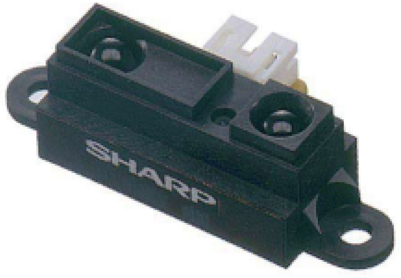
Figure 2.
Voltage to distance relationship per the [10]
Figure 2.
Voltage to distance relationship per the [10]

Figure 4.
AKDK 1 MP, 120FOV, 3-D ToF Camera
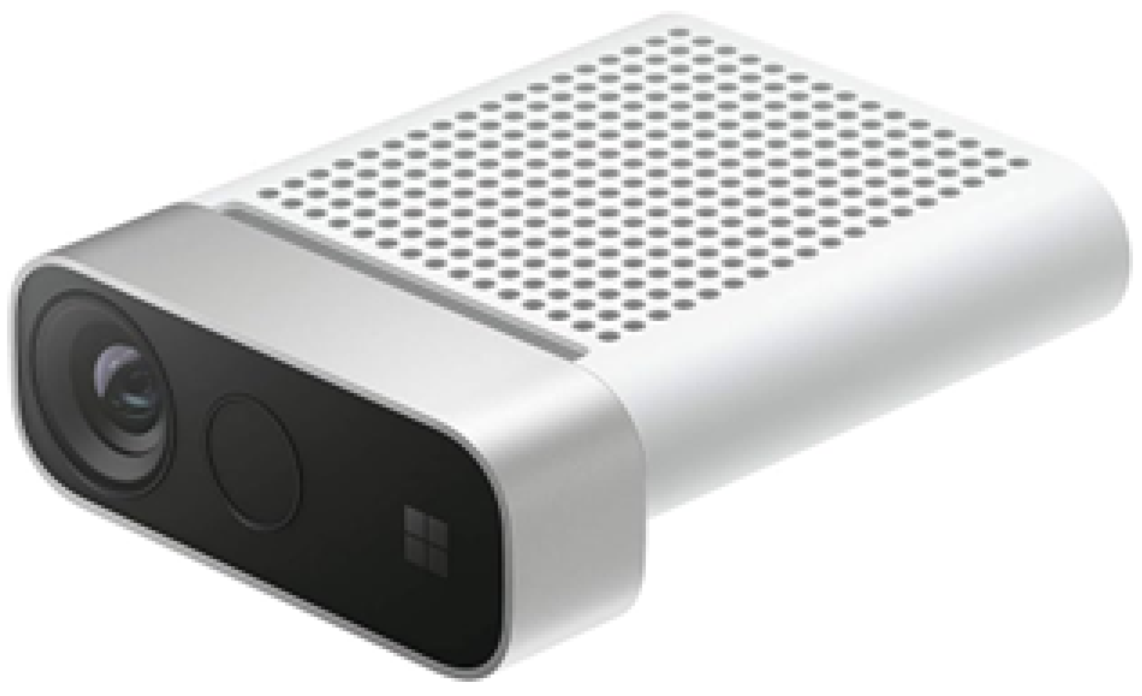
Figure 5.
VL53l1x 4 M max, 50 Hz max, 27FOV, ToF Sensor
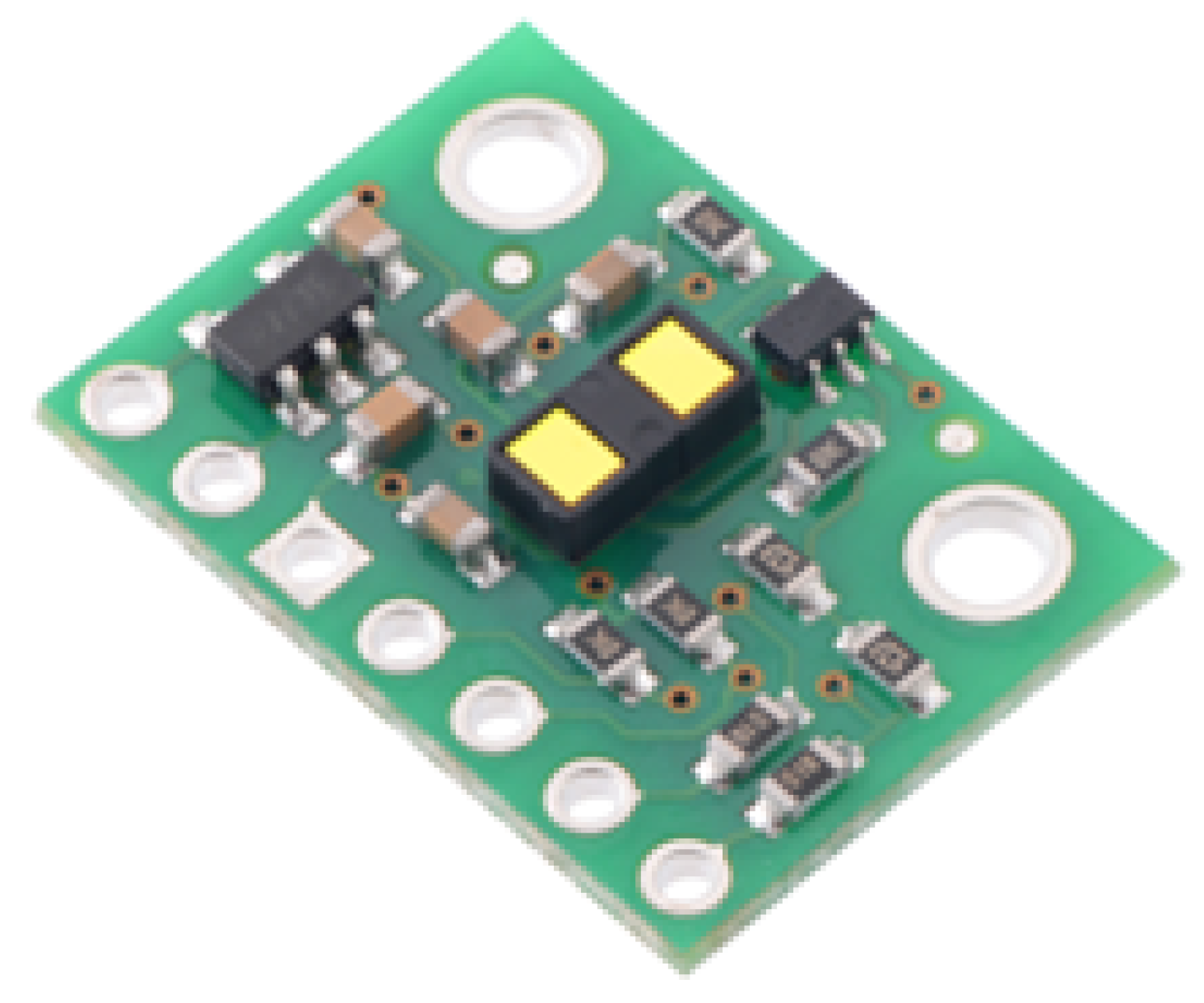
Figure 7.
Intel D435i Stereoscopic Camera
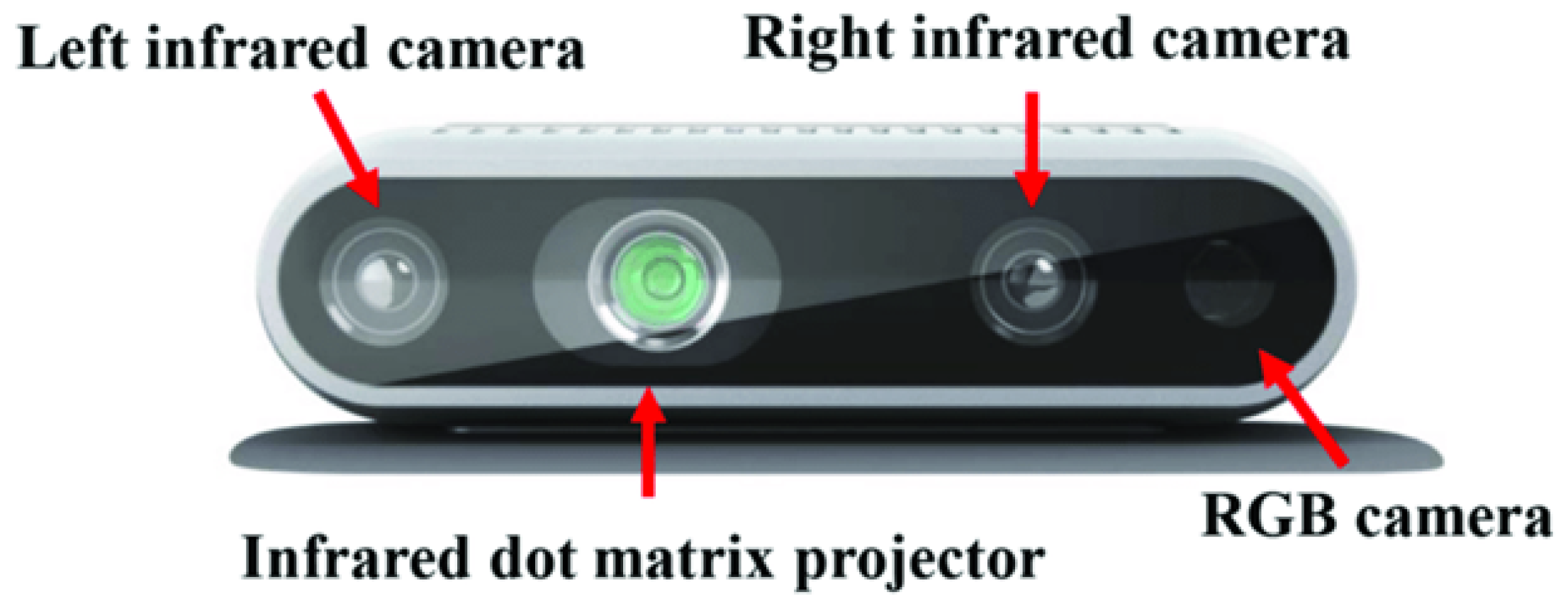
Figure 8.
"TeraRanger Evo Thermal 33 Sensor"
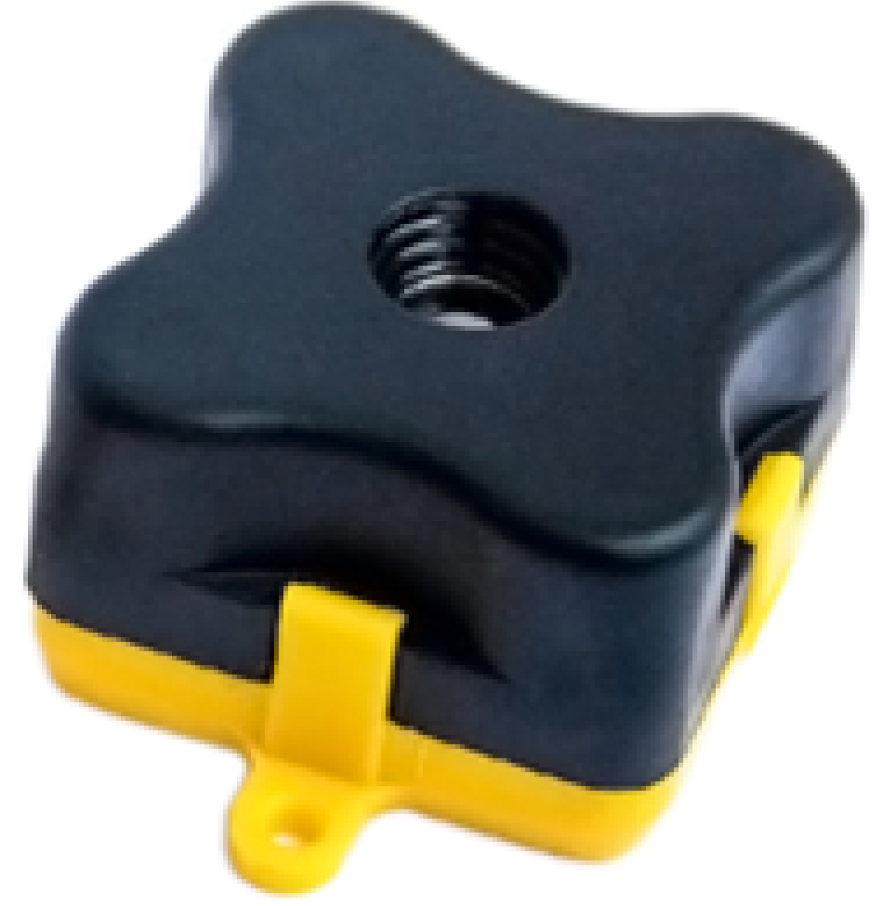
Figure 9.
"TeraRanger Evo Thermal 33 Sensor"
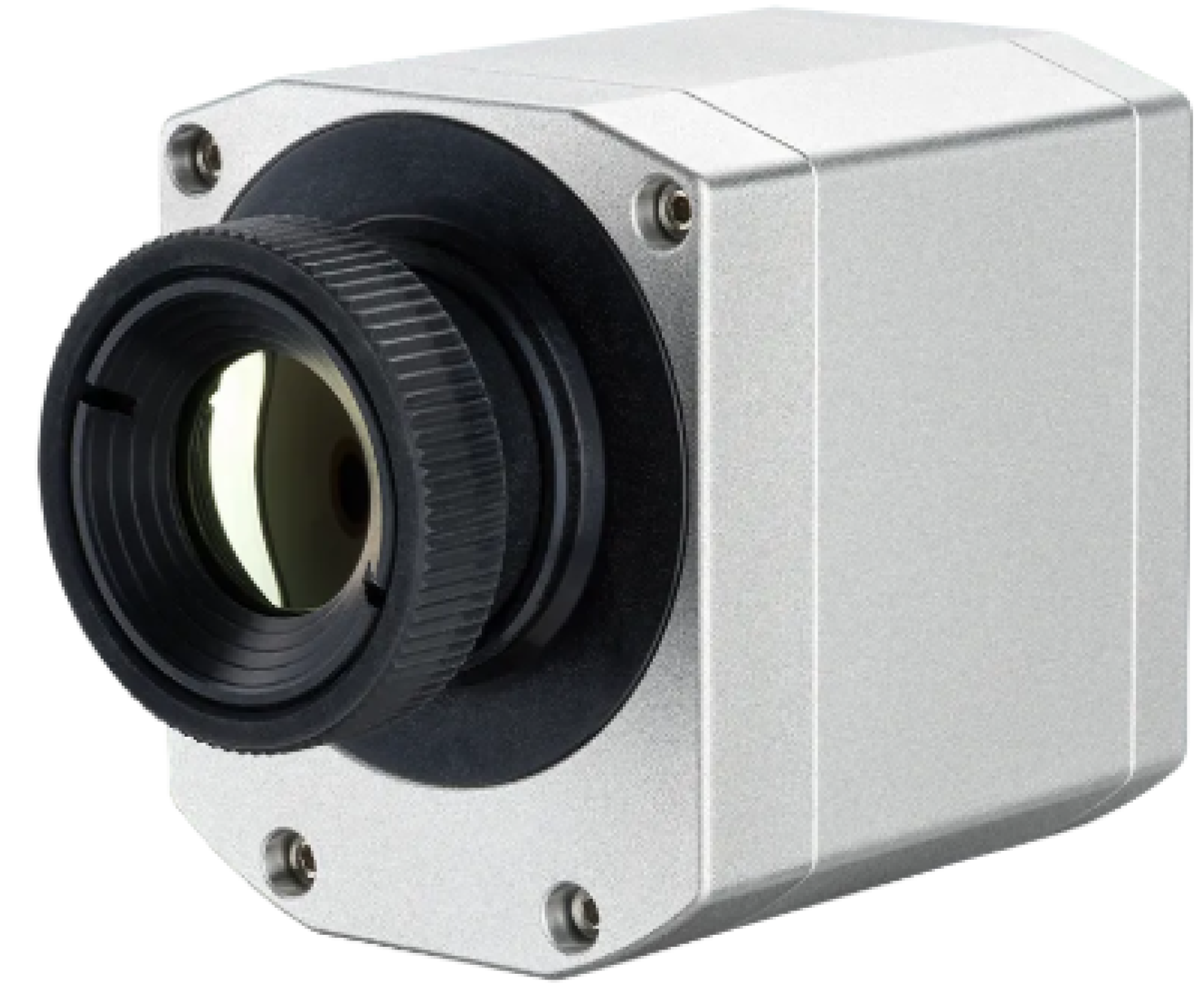
Figure 10.
SSM System Architecture
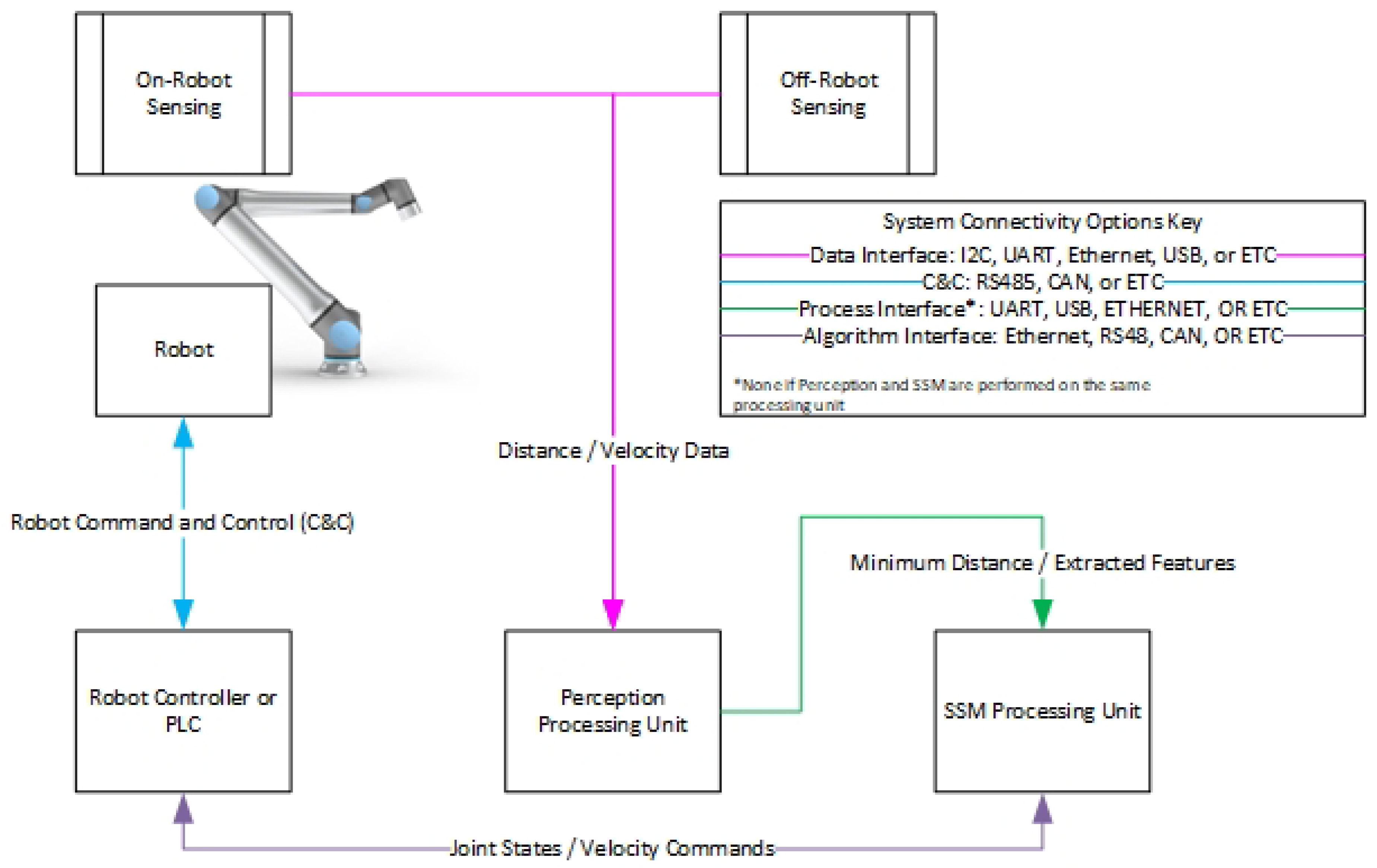
Figure 11.
NUCLEO-F030R8 is an STM32 Microcontroller Evaluation Board. This is a common example of a platformed used for sensor processing.
Figure 11.
NUCLEO-F030R8 is an STM32 Microcontroller Evaluation Board. This is a common example of a platformed used for sensor processing.
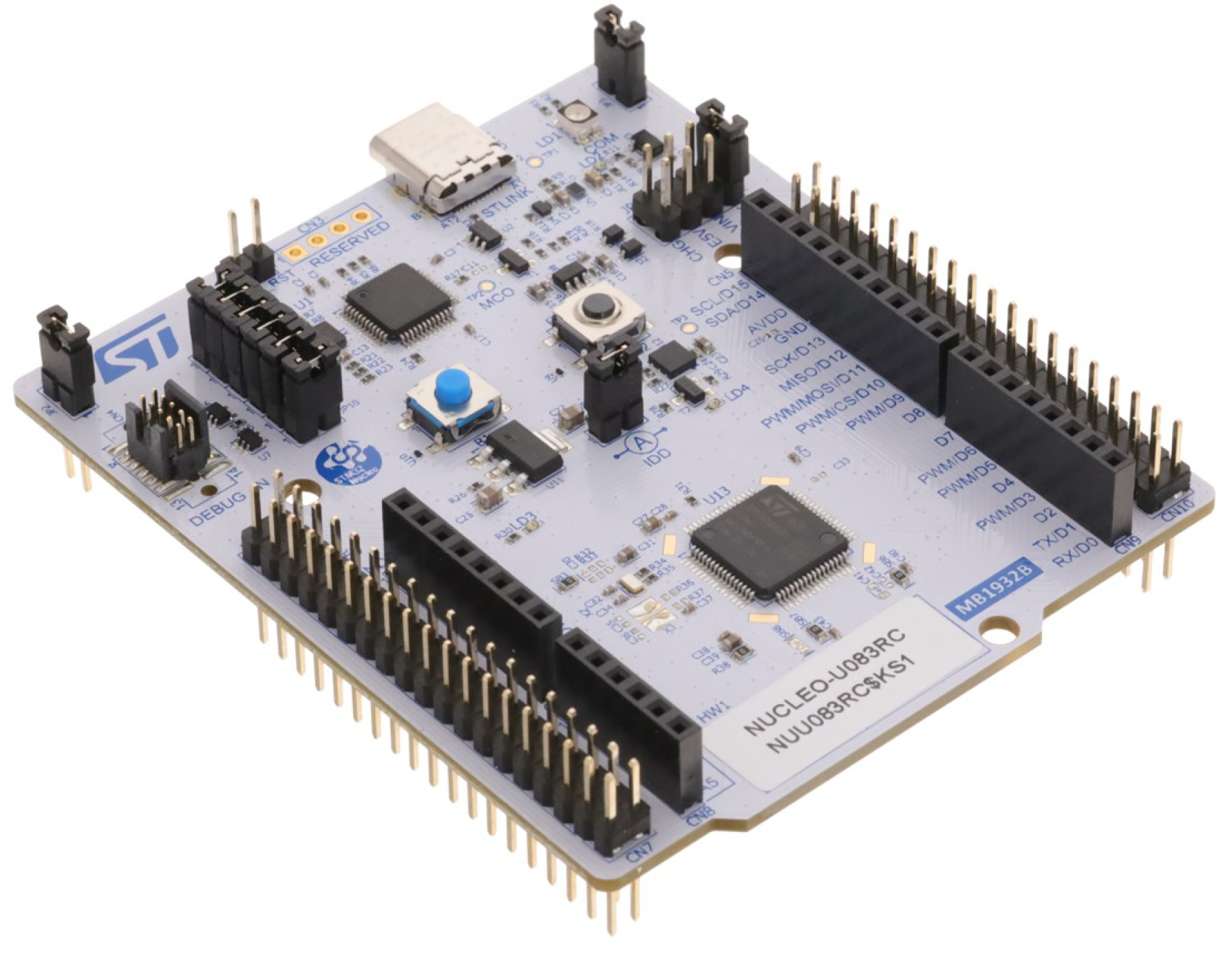
Figure 13.
Peer review citation generation and tagging workflow.
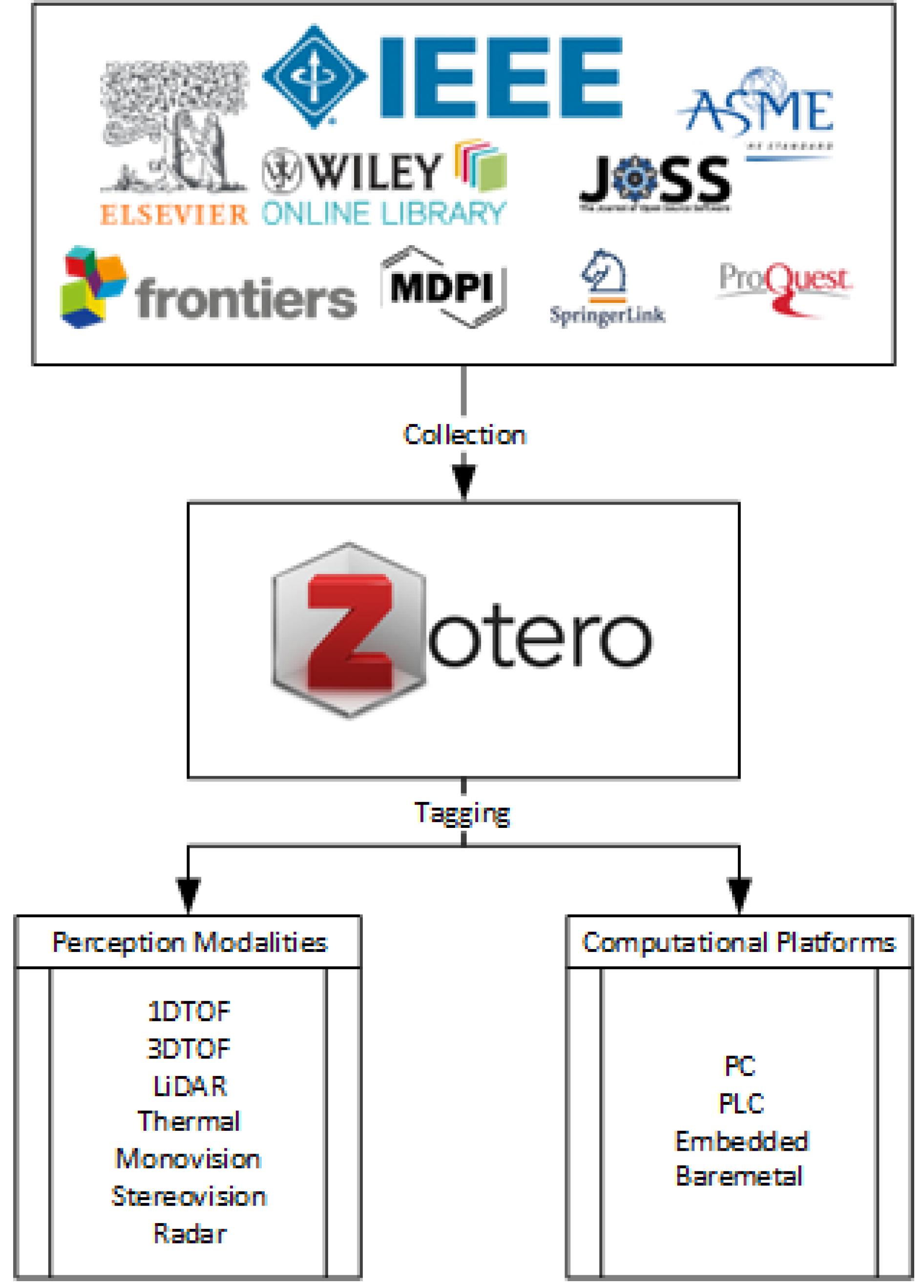
Figure 14.
Inciteful web of related works in SSM Architecture survey which reference one another
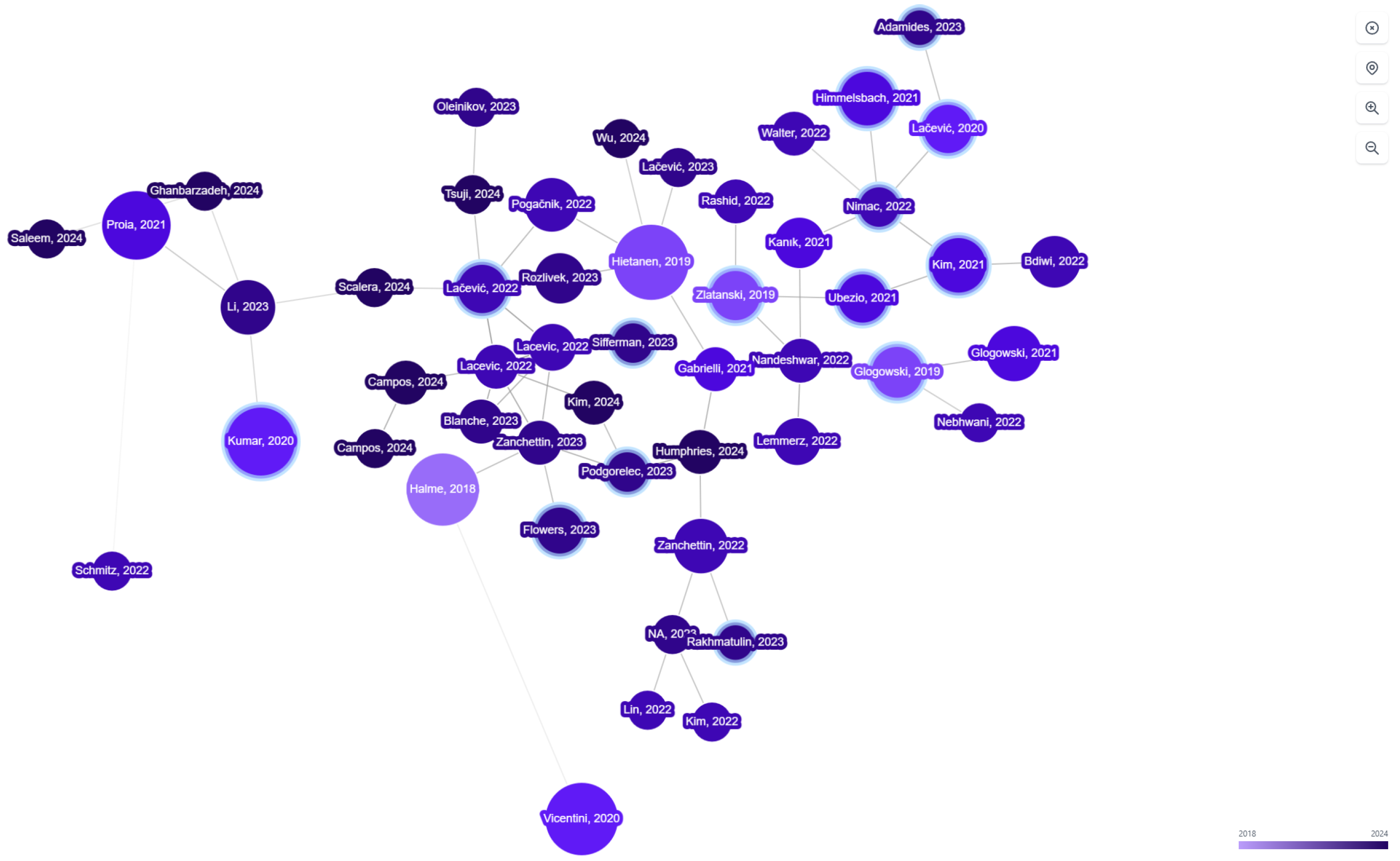
Figure 15.
(15a) Histogram of sensor types in the dataset. (15b) Histogram of computational platform types in the dataset.
Figure 15.
(15a) Histogram of sensor types in the dataset. (15b) Histogram of computational platform types in the dataset.
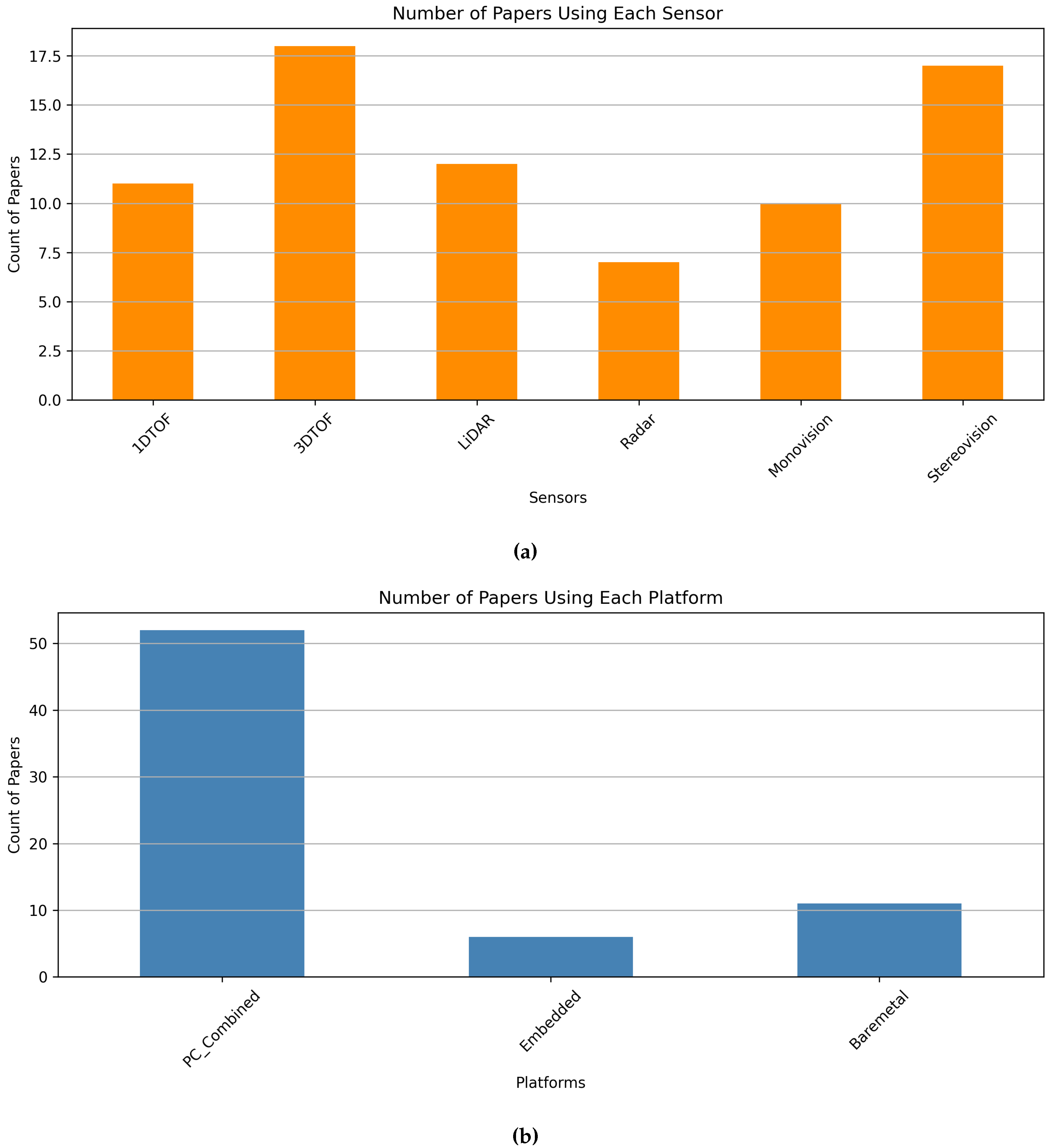
Figure 16.
Timeline usage of different sensor modalities across SSM research
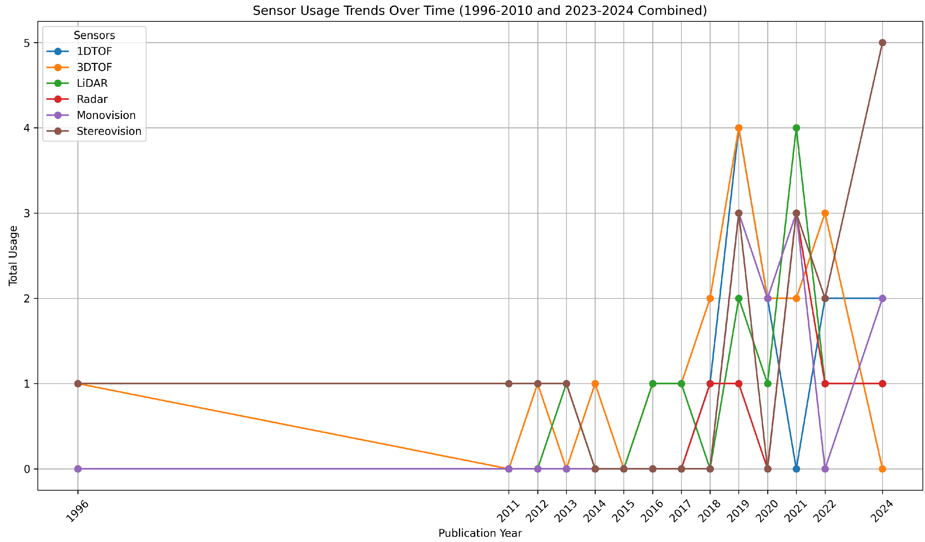
Figure 17.
Migration of different sensor modalities used in SSM research over time
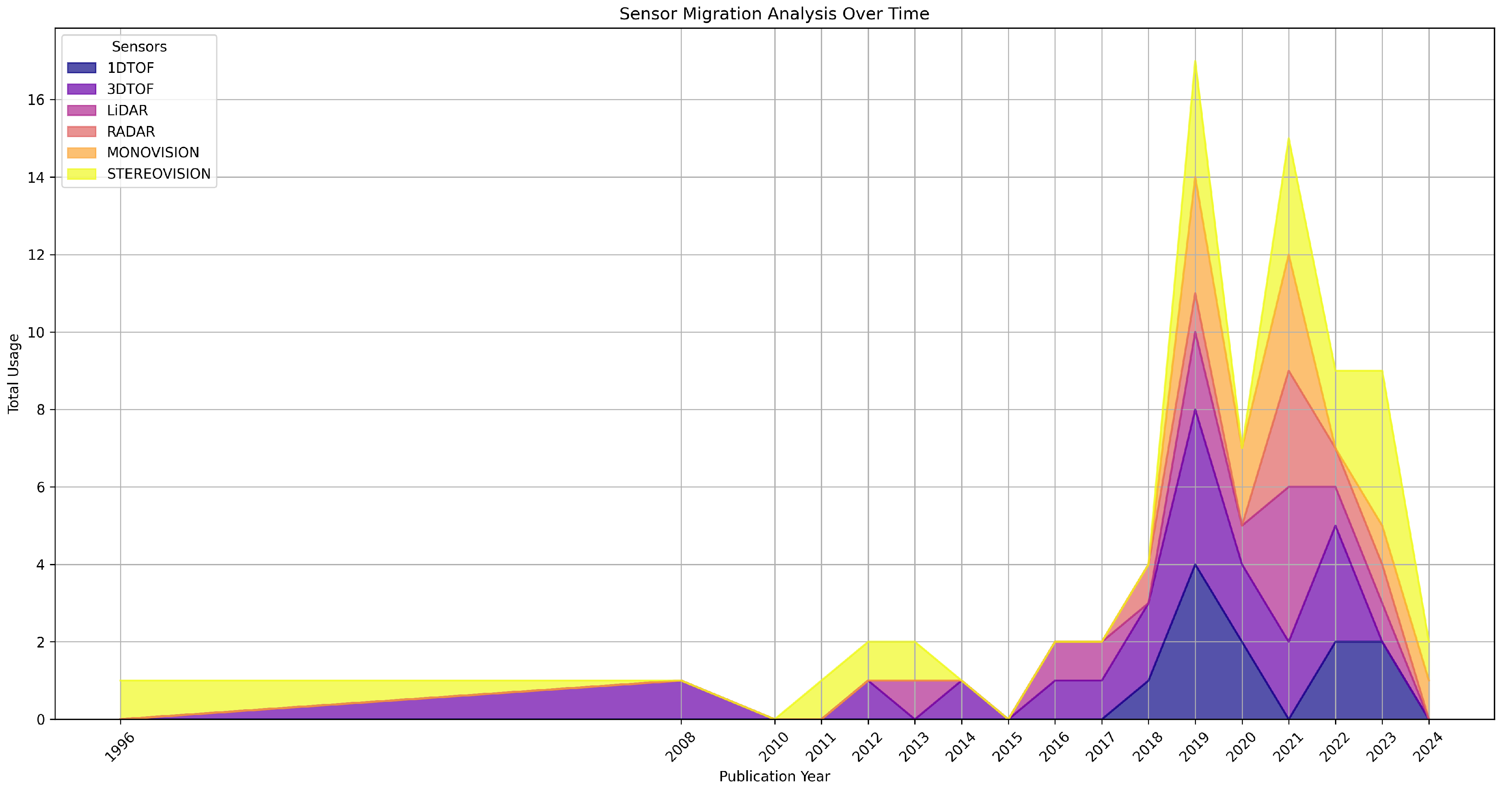
Figure 18.
Timeline Usage of different computation units across SSM research
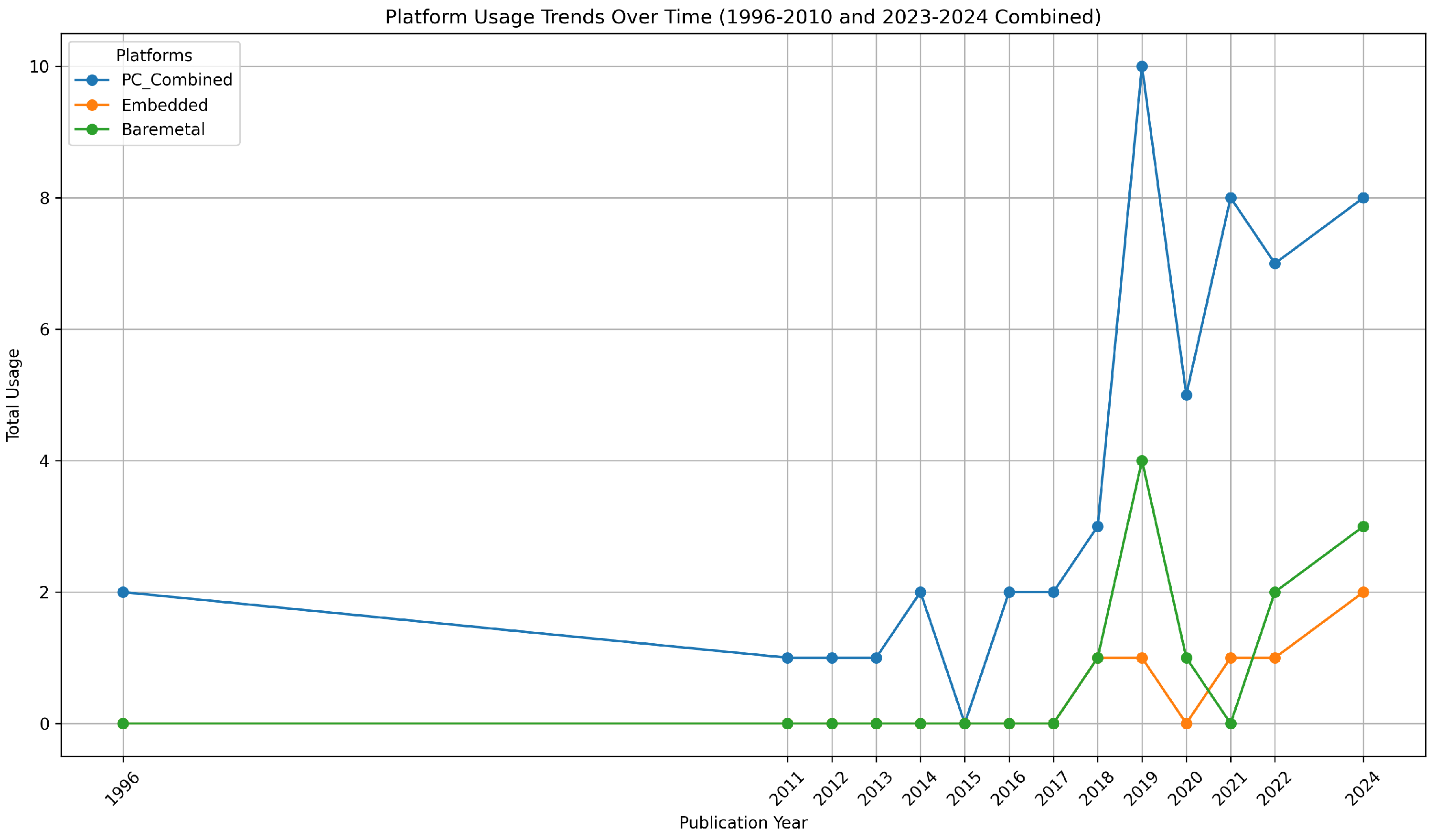
Figure 19.
Migration of different computation units used in SSM research over time
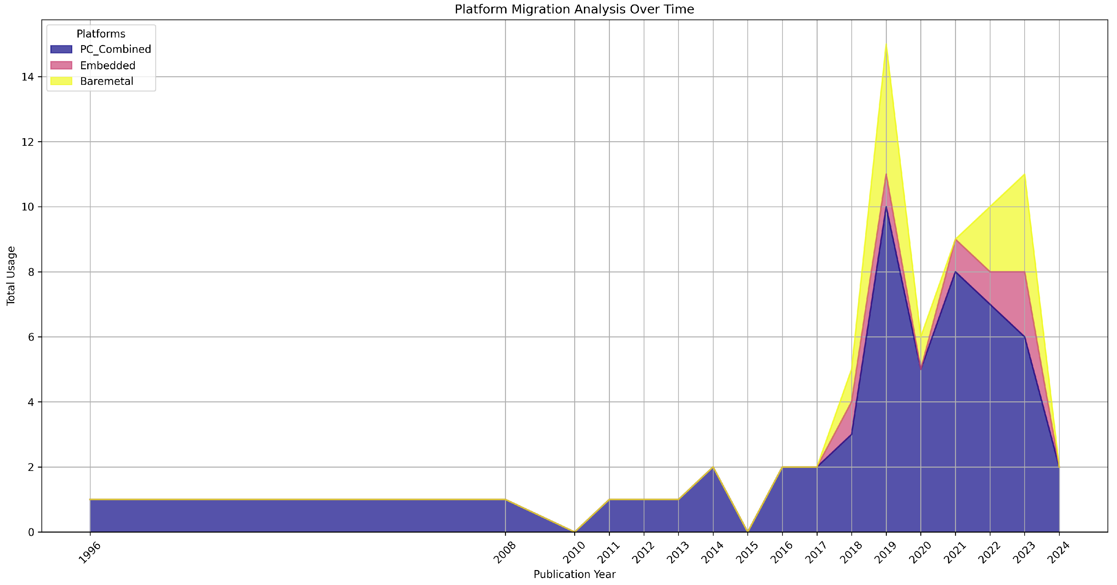

Table 1.
Key works in SSM Architecture Research
| Reference | Category | Hardware |
|---|---|---|
| Zhang, Chenyang; et al. [70] | Monovision, Stereovision | PC |
| Rakhmatulin, Viktor; et al. [77] | Monovision, MOCAP | Embedded, Baremetal |
| Ubezio, Barnaba; et al. [60] | Radar | PC |
| Podgorelec, David; et al. [23] | – | Embedded |
| Flowers, Jared; et al. [68] | Stereovision | PC |
| Rashid, Aquib; et al. [21] | LiDAR, Stereovision | PC |
| Tsuji, Satoshi; et al. [52] | 1DToF | Baremetal |
| Tsuji, Satoshi [53] | 1DToF | Baremetal |
| Amaya-Mejía, Lina María; et al. [46] | 3DToF | PC |
| Yang, Botao; et al. [71] | Thermal, Stereovision | PC |
| Sifferman, Carter; et al. [88] | 1DToF | Baremetal |
| Karagiannis, Panagiotis; et al. [69] | Stereovision | PC, PLC |
| Lacevic, Bakir; et al. [37] | 3DToF | PC, Embedded |
| Park, Jinha; et al. [16] | 3DToF, LiDAR | PC |
| Lu, Chen-Lung; et al. [17] | 3DToF, LiDAR, Radar | Embedded |
| Ubezio, Barnaba; et al. [63] | Radar | PC |
| Costanzo, Marco; et al. [35] | Thermal, Monovision, Stereovision | PC |
| Scibilia, Adriano; et al. [5] | – | – |
| Lucci, Niccolo; et al. [39] | 3DToF | PC |
| Rashid, Aquib; et al. [24] | LiDAR, Monovision | PC |
| Du, Guanglong; et al. [34] | 3DToF, Monovision | PC |
| Tsuji, Satoshi; et al. [50] | 1DToF | Baremetal |
| Glogowski, Paul; et al. [41] | 3DToF | PC |
| Svarny, Petr; et al. [73] | Monovision, Stereovision | – |
| Antão, Liliana; et al. [75] | Stereovision | PC |
| Kumar, Shitij; et al. [28] | 1DToF | PC, Baremetal |
| Benli, Emrah; et al. [36] | Thermal, Stereovision | PC |
| Lemmerz, Kai; et al. [79] | 3DToF, Monovision | PC |
| Kumar, Shitij; et al. [48] | 1DToF | PC, Baremetal |
| Hughes, Dana; et al. [47] | 1DToF | PC, Baremetal |
| Marvel, Jeremy A.; et al. [27] | LiDAR | PC |
| Zanchettin, Andrea Maria; et al. [45] | 3DToF | PC |
| Marvel, Jeremy A. [12] | LiDAR, Stereovision, MOCAP | PC |
| Tan, Jeffrey Too Chuan; et al. [66] | Stereovision | PC |
| Lacevic, Bakir; et al. [91] | – | – |
Abbreviations: Monovision—Single image sensor used for human classification, Stereovision—Stereo camera used for depth, MOCAP—Motion Capture System used for depth or calibration, Radar—LMCFW Radar used for depth, LiDAR—LiDAR used for depth, 1DToF—1-D time-of-flight Sensors used for Depth, 3DToF—3-D time-of-flight Camera used for depth, Thermal—Thermal Imager or sensor used for depth or human classification, PC—PC used for perception processing and or SSM algorithm, Embedded—Embedded platform like NVIDIA Jetson or Intel NUC was used for perception processing, Baremetal—Microcontroller or Microprocessor was used for perception processing, PLC—Programmable logic controller was used for perception processing and or SSM algorithm
Disclaimer/Publisher’s Note: The statements, opinions and data contained in all publications are solely those of the individual author(s) and contributor(s) and not of MDPI and/or the editor(s). MDPI and/or the editor(s) disclaim responsibility for any injury to people or property resulting from any ideas, methods, instructions or products referred to in the content. |
© 2025 by the authors. Licensee MDPI, Basel, Switzerland. This article is an open access article distributed under the terms and conditions of the Creative Commons Attribution (CC BY) license (http://creativecommons.org/licenses/by/4.0/).
Copyright: This open access article is published under a Creative Commons CC BY 4.0 license, which permit the free download, distribution, and reuse, provided that the author and preprint are cited in any reuse.


