Submitted:
10 February 2025
Posted:
11 February 2025
You are already at the latest version
Abstract
In this study, we present a novel design methodology for unit cells in chessboard metasurfaces, aimed at reducing the radar cross-section (RCS) for linearly polarized waves. The design employs rotational symmetry and incorporates ten continuous parameters to define the metasurface units, enabling the creation of flexible 2D structures. The geometrical parameters of the two units are then optimized using a simulated annealing (SA) algorithm to achieve a low RCS chessboard metasurface. Following optimization, the properties of metasurface were ex perimentally verified. Experimental results show a significant RCS reduction of 10 dB within the 7.6–15.5 GHz range, with a peak reduction reaching-28 dB at normal incidence. For bistatic RCS, the metasurface effectively scatters incident waves into four distinct lobes. The proposed method offers an alternative strategy for the inverse design of low RCS metasurfaces and can be extended to applications in polarization control, phase gradient manipulation, and transmissive metasurfaces.
Keywords:
Radar cross section (RCS)
; inverse design
; artificial magnetic conductor (AMC)
; simulated annealing
; broadband
1. Introduction
In recent years, rapid advancements in radar detection technology have made the stealth capabilities of various weapons, equipment, aircraft, and ships a critical area of research. Common approaches to enhancing stealth include reshaping and using absorptive materials [1,2,3,4,5]. A key pa rameter for evaluating the stealth performance of an ob ject under radar illumination is the RCS, which quantita tively characterizes the scattering properties of a target [6]. Metasurface, which are ultra-thin, two-dimensional structures composed of subwavelength unit elements arranged in quasi periodic configurations, offer a powerful tool for manipulating the polarization, amplitude, and phase of electromagnetic (EM) waves. Due to their unique electromagnetic properties, metasurfaces have been widely used in RCS reduction, such as polarization rotation metasurfaces (PVM) [7,8,9,10], phase gradient metasurfaces (PGM) [11,12,13], and artificial magnetic conductor (AMC) metasurfaces [14,15,16,17,18].
AMC refers to a class of metasurfaces are characterized by their ability to reflect electromagnetic waves with a phase matching the incident wave. This property makes them highly effective in reducing RCS when arranged in a chessboard configuration with Perfect Electric Conductor(PEC). In such configurations, adjacent units cancel each other out due to a 180° phase difference in the reflected electromagnetic waves (PEC reflects with a 180° phase shift, while AMC reflects with a 0° phase shift) [15]. However, achieving a high bandwidth chessboard metasurfaces is still challenging. To address it, Cheng et al. arranged two types of AMC units with nearly 180 degree phase difference in a chessboard layout, achieving a 10-dB reduction band from 14.9 to 16.3 GHz, with a peak value reaching-31.9 dB [16]. Su et al. further extended the bandwidth by using 16 different AMC units with varying sizes and dielectric layer thicknesses to achieve a 10-dB RCS reduction band from 5.5 to 32.3 GHz [17]. Similarly, Modi et al. achieved a 10-dB RCS reduction band from 3.75 to 10 GHz by arranging four types of AMC in a chessboard pattern with irregular areas [18]. While these advanced AMC metasurface, including PGM and PRM, significantly improve bandwidth, they require complicated arrangements and involve a large number of AMC units with varying heights. This complexity increases both manufacturing and design costs compared to simpler chessboard patterns, making it challenging to integrate these designs with target objects.
Traditionally, most metasurface design approaches focus on adjusting or scaling specific geometric shapes, such as Jerusalem crosses, split rings, and square patches. In recent years, deep learning methods have also been applied in the design of metasurface. For examples, in [19,20], neural networks were employed to map electromagnetic responses to pixel matrices, which represent metasurface geometries. These trained networks can directly derive geometric struc tures from electromagnetic responses. Generative adversarial networks (GANs) can, to some extent, enhance the diversity and flexibility of the designs. By training the generator and dis criminator on a dataset with similar properties, new structures can be obtained, although this method still largely depends on the dataset [21,22]. Variational autoencoders (VAEs) take a different approach by encoding two-dimensional discrete matrices into continuous latent variables, which can then be decoded back into two-dimensional structures. Additionally, a neural network is trained to map these latent variables to electromagnetic responses, enabling optimization within the latent space to satisfy design criteria. While the continuous nature of the latent variables somewhat enhances design f lexibility but remains closely tied to the dataset. Moreover, the underlying physical mechanisms of the latent variables remain unclear, and achieving accuracy and success in design remains challenging throughout the entire process, from matrix encoding to decoding and electromagnetic response prediction networks [23,24]. A fundamental limitation of these deep learning (DL)-based methods is their pixel-like representation of metasurface structures, which restricts the generation of novel geometric structures. The resulting isolated pixel points also create significant challenges in terms of manufacturability.
In this paper, we propose a new method for designing metasurface unit cells. Instead of relying on pixel-based rep resentations, we model unit cells using ten continuous param eters for a greater variety of shapes and more flexible phase control. Additionally, by ensuring the rotational symmetry of the cells, we achieve polarization insensitivity. The continuous variable form is also more advantageous for optimization algorithms compared to discrete matrices. By combining the simulated annealing algorithm to optimize the parameters, a chessboard metasurface is constructed, achieving a wideband 10-dB RCS reduction from 7.6 to 15.5 GHz. This method provides a new paradigm for designing novel foundational structures in metasurfaces, enabling greater design flexibility and performance.
2. Design Theory and Method
2.1. Design and Structures
As show in Figure 1, a chessboard metasurface typically consists of alternating arrangements of AMC1 block and AMC2 block, resembling a checkerboard pattern, with each block containing n × n unit cells. When a plane wave is incident upon this metasurface, the two types of AMC blocks exhibit different phase and amplitude responses to the incident wave:
where and respectively denote the electric fields of incident and reflected waves for AMC1 and AMC2 blocks, while φn and An represent the reflection phase and amplitude for the incident wave by both AMC types. By utilizing the definition of RCS,it is known that compared to same-size PEC (with a reflectivity of 1), the RCS reduction in dB can be calculated as follows [25]:
Considering the equal areas of both types of AMC, it is reasonable to assume that . Additionally, due to the presence of the ground layer, it is evident that . By synthesizing the formulas mentioned above, the RCS reduction can be represented using and To achieve a reduction greater than -10 dB, the following condition must be satisfied:
Solving above equation, it becomes apparent that a phase difference ranging from 143°to 217° can result in an RCS reduction exceeding 10 dB. For simplicity and to ensure the effectiveness of the RCS reduction in practical applications, an effective phase difference of 180°±30°is adopted.
Due to the complex correlation between the phase response and geometric structure, it is challenging to define these relationships precisely. To achieve diverse reflect phase, we manipulate the geometrical structure of the metasurface using ten parameters.
During the parameterization process of AMC, a square canvas of dimensions w×w, determined by the unit cell width w, is initially prepared. On this canvas, two rectangular con ductive elements, with predefined dimensions, center coordi nates, and rotation angles, are positioned as depicted in Figure 2(a). These rectangles are then symmetrically duplicated along the canvas’s diagonal, resulting in four identical rectangles. Subsequent symmetrical duplication along both the horizontal and vertical axes, with the canvas center as the reference point, yields a unit cell composed of 16 rectangular elements, as show in Figure 2(b),and the unit cells are constructed using an FR4 dielectric substrate, which possesses a thickness of 3 mm and a relative permittivity of 4.4 [26]. Governed by a set of 10 parameters, this methodology enables the sculpt ing of the unit cell’s geometry. Strategic operations such as symmetrical duplication facilitate the creation of unit cells with various configurations, thereby enabling diverse phase responses. Moreover, the unit cells generated by this method exhibit rotational symmetry (remaining identical upon a 90° rotation), thereby offering polarization insensitivity.
2.2. Optimazation of Unit Cell
The foundmental principle of simulated annealing algorithm is to mimics the annealing process of a physical system at high temperatures, which is more suitable for this type of single-objective continuous parameter optimization problem compared to algorithms like GA and PSO. By gradually lowering the system’s temperature, it guides the system towards a state of minimum energy, achieving a global optimum [27]. Therefore, leveraging its precise tuning capability for continuous parameters and flexible search space, combined with the unit cell parameterization method proposed in this paper, can design a metasurface structure that meets the specified objectives. In this study, the objective function for simulated annealing is to match the phase difference of two unit cells within the 6-18 GHz band to 180°±30°. To achieve accurate simulation results, use frequency-domain solver of CST and set the Floquet boundaries along the x and y directions. The overall design process is shown in Figure 3.
After the simulated annealing process, a set of optimized solutions with a bandwidth of 7.6 GHz (as shown in Table 1) was selected for a chessboard metasurface to validate the effectiveness of this SA-based method. The reflection phases and phase differences of the two unit cells are shown in Figure 4. Each AMC is composed of 7×7 cells, and the proposed metasurface consists of 4×4 AMC blocks. The total size of the designed chessboard metasurface is 280 mm × 280 mm × 3 mm. The RCS of the aforementioned metasurface was simulated using the time-domain solver of CST (based on the Finite Integration Technique), and the fabricated metasurface and overall structure are shown in Figure 5. To gain deeper physical understanding, we examine the distributions of surface currents at zero reflection phase frequency point of unit cell#1’s upper and ground layer. As shown in Figure 6, at 5.77 GHz, the antiparallel surface currents create a magnetic resonance. At 10.94 and 16.7 GHz, the central part of the unit cell exhibits currents in the opposite direction to those on the ground, forming magnetic resonances, while the peripheral parts have currents in the same direction as the ground, forming electric resonances. These multiple resonances together result in several zero-phase reflection points within the 8-17 GHz frequency range.
3. Experiment Results
The architecture of the measurement setup is illustrated in Figure 7, comprising two horn antennas operating in the 2-18 GHz frequency range connected to a Vector Network Analyzer (VNA), and aligned with the center of the metasurface. Additionally, a PEC plane of the same dimensions as the Chessboard metasurface is fabricated to serve as a reference.Using the aforementioned system, the transmission coefficients of PEC and Chessboard metasurface are measured separately. By subtracting one from the other, the RCS reduction can be obtained.
3.1. Monostatic Results
As shown in Figure 8, it should be noted that the measured 10-dB RCS reduction bandwidth is from 7.6 to 15.5 GHz, which closely matches the simulated bandwidth of 7.6 to 15.7 GHz obtained from RCS simulations(x-polarization). Moreover, this is in agreement with the phase difference simulations of the unit cell pair within the 180±30° frequency band. Within this frequency band, the maximum attenuation was observed to be -28 dB at 10 GHz, with the RCS also reaching -20 dB at 15.1 GHz. Additionally, for oblique incidence, the monostatic RCS reduction, as shown in Figure 9, demonstrates that this metasurface maintains a stable reduction effect for incident angles ranging from 0 to 30 degrees. It can be observed that deviation between the measured and simulated results may be attributed to the fabrication process of the proposed cell pair, which involves several rectangles with a width of 0.1 mm.
3.1. Bistatic Results
Figure 10 illustrates the bistatic 3-D RCS patterns for both the Chessboard metasurface and a PEC surface of the same size at frequencies of 8, 10, and 12 GHz, with incident waves striking the surface perpendicularly (normal incidence). At these frequencies, the PEC surface reflects nearly all incident waves back in the direction of incidence. In contrast, the proposed metasurface reflects the waves predominantly into four distinct directions, forming four lobes, none of which align with the normal direction, This phenomenon can be explained by the generalized Snell’s law [11]: the metasurface generates a phase gradient in multiple directions within the xy-plane, causing the reflected waves to deviate from the principal axis. This observation is consistent with the findings in [31].
Table 2 showcases a comparison of the performance metrics of the proposed metasurface against those of other published works. This comparison highlights that proposed metasurface not only exhibits superior performance in the 10-dB RCS reduction band but also demonstrates outstanding performance in oblique incident angel.
Figure 11.
Simulated 3-D RCS Patterns of metasurface and PEC at 8.4, 12.1 and 14.6 GHz. (a)-(c) Chessboard metasurface. (d)-(f) PEC surface.
Figure 11.
Simulated 3-D RCS Patterns of metasurface and PEC at 8.4, 12.1 and 14.6 GHz. (a)-(c) Chessboard metasurface. (d)-(f) PEC surface.
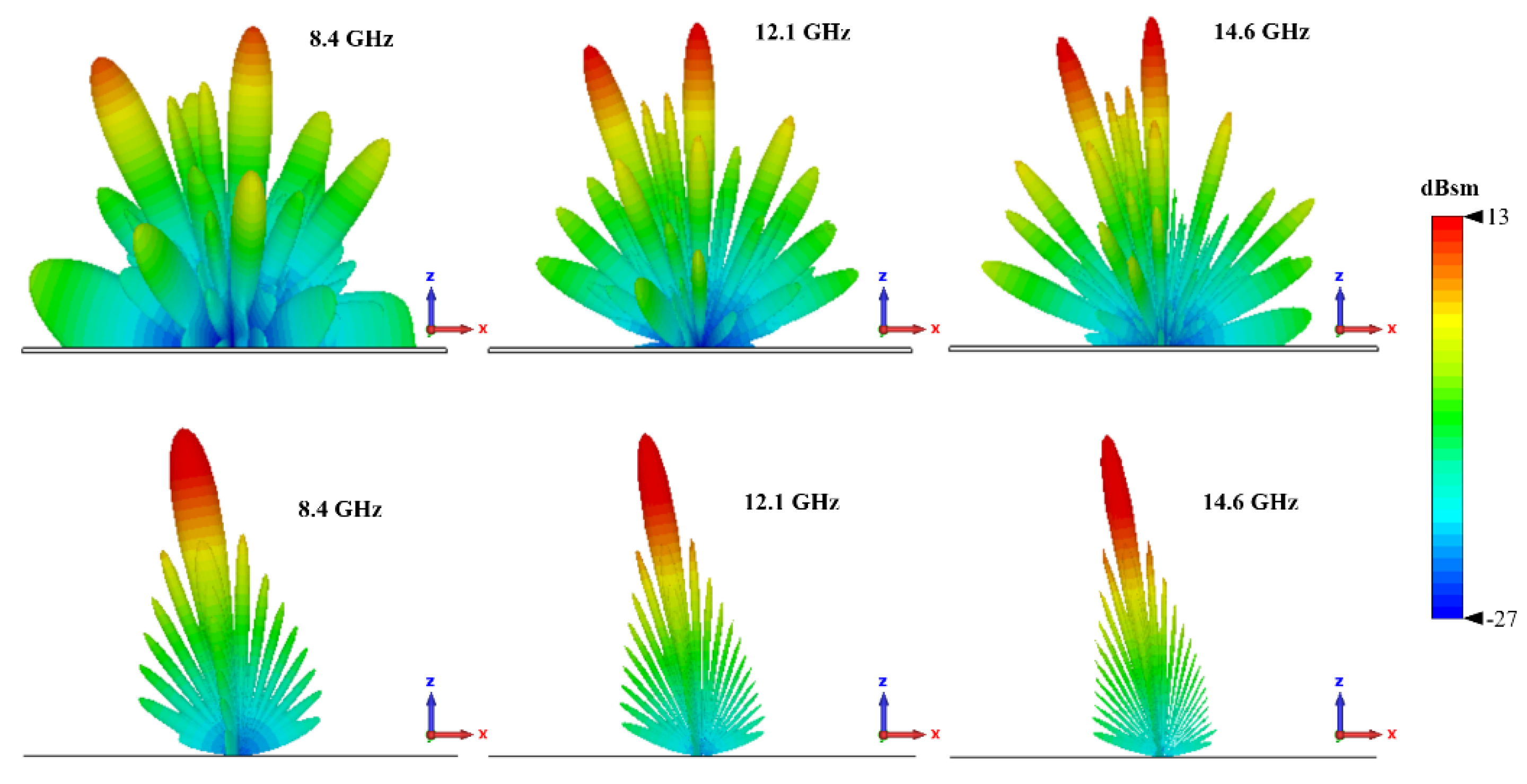
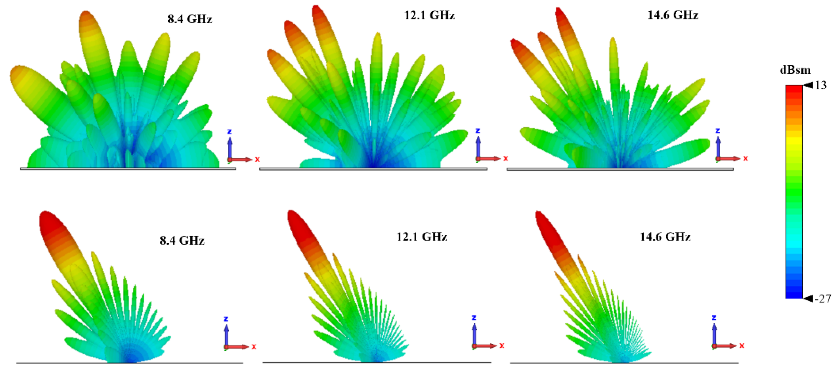
Figure 12.
Simulated 3-D RCS Patterns of metasurface and PEC at 8.4, 12.1 and 14.6 GHz under 30 degree incident angel. (a)-(c) Chessboard metasurface. (d)-(f) PEC surface.
Figure 12.
Simulated 3-D RCS Patterns of metasurface and PEC at 8.4, 12.1 and 14.6 GHz under 30 degree incident angel. (a)-(c) Chessboard metasurface. (d)-(f) PEC surface.
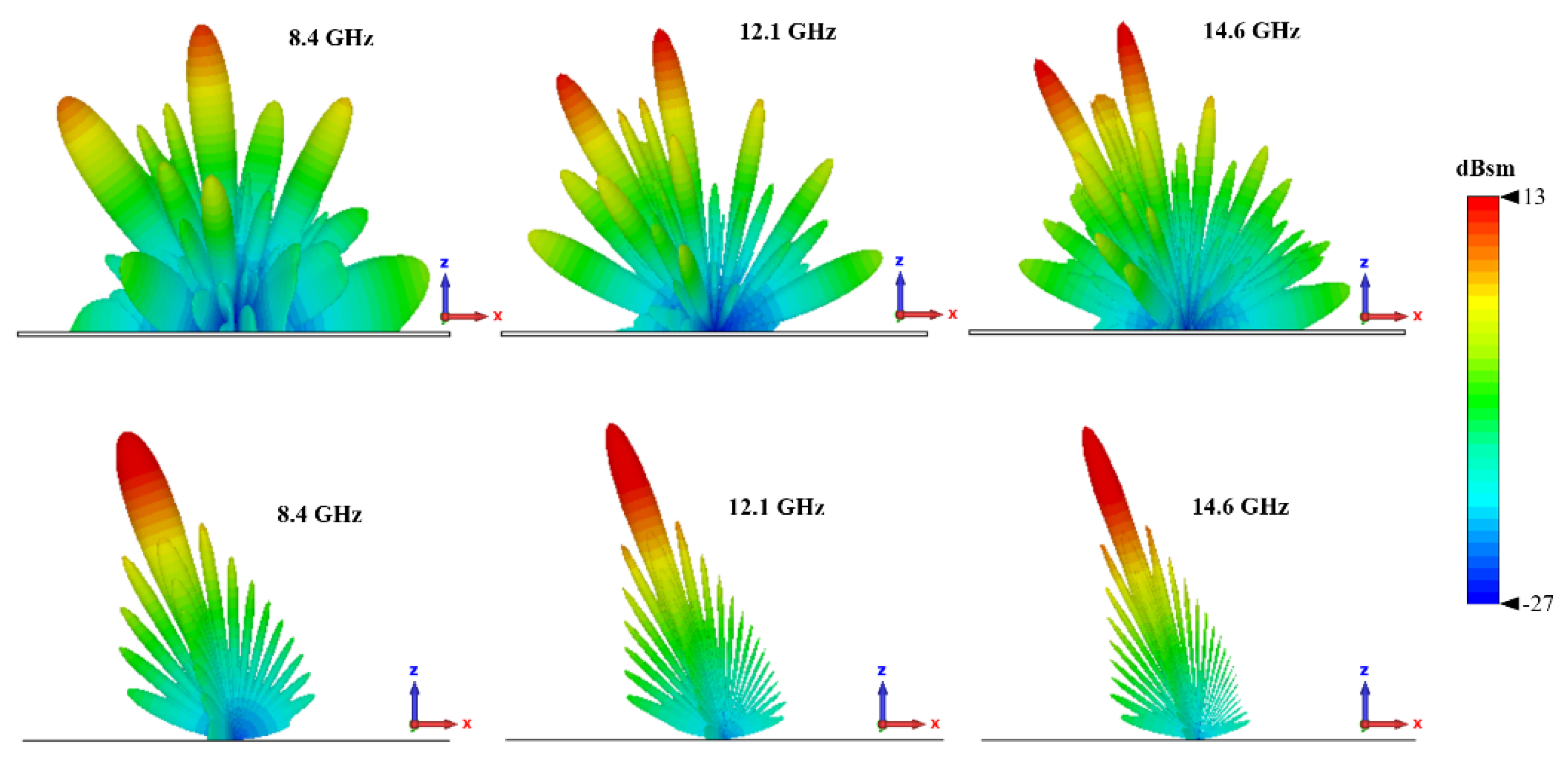
Figure 13.
Simulated 3-D RCS Patterns of metasurface and PEC at 8.4, 12.1 and 14.6 GHz. (a)-(c) Chessboard metasurface. (d)-(f) PEC surface.
Figure 13.
Simulated 3-D RCS Patterns of metasurface and PEC at 8.4, 12.1 and 14.6 GHz. (a)-(c) Chessboard metasurface. (d)-(f) PEC surface.
4. Conclusion
In this work, a novel approach for the inverse design of metasurface unit cells aimed at RCS reduction was proposed. Instead of relying on a matrix or pixel-based representation, we model the unit cells using a limited set of parameters combined with rotational symmetry. This strategy allows us to achieve a broader range of structural designs without the requirement for extensive data. Additionally, by optimizing the phase difference between the parameterized unit cells using a simulated annealing (SA) algorithm, we successfully achieve broadband RCS reduction. The optimized unit cell pair demonstrates a 10-dB reduction in RCS over the 7.6–15.5 GHz frequency range, with excellent angular stability. The adaptability of this method enables optimization across arbitrary frequency bands by adjusting the substrate thickness and unit cell period. Moreover, the approach can be extended to design other types of metasurfaces, such as PGMs and PVMs, by incorporating different objective functions and rotational symmetry strategies.
Author Contributions
Conceptualization, H.X.; methodology, H.X.; software, H.X. writing—original draft preparation,H.X.; validation, X.L.; formal analysis, B.J.; investigation, P.S.; data curation, Z.C.; supervision, N.X.; writing—review and editing, S.P.; All authors have read and agreed to the published version of the manuscript.
Funding
This research was supported in part by the National Science and Technology Major Project grant number 2021ZD0114600, the Fundamental Research Funds for the Central Universities, grant number 2024-LXY-B1-01, National Natural Science Foundation of China, grant number 62104174, and partly by the National Innovation & Entrepreneurship Training Program for College Students grant number 20240100435.
References
- Shin, H.; Yoon, D.; Kim, C.; Yang, Y.S.; Lee, M.G.; Park, J.Y.; Hwang, K.C.; Park, Y.B. Shape Optimization of an Integrated Mast for RCS Reduction of a Stealth Naval Vessel. Applied Sciences 2021, 11, 2819. [Google Scholar] [CrossRef]
- Feng, J.; Zong, Y.; Sun, Y.; Zhang, Y.; Yang, X.; Long, G.; Wang, Y.; Li, X.; Zheng, X. Optimization of Porous FeNi3/N-GN Composites with Superior Microwave Absorption Performance. Chemical Engineering Journal 2018, 345, 441–451. [Google Scholar] [CrossRef]
- Breiss, H.; El Assal, A.; Benzerga, R.; Sharaiha, A.; Jrad, A.; Harmouch, A. Ultra-Porous and Lightweight Microwave Absorber Based on Epoxy Foam Loaded with Long Carbon Fibers. Materials Research Bulletin 2021, 137, 111188–111188. [Google Scholar] [CrossRef]
- Pozar, D.M. RCS Reduction for a Microstrip Antenna Using a Normally Biased Ferrite Substrate. IEEE Microwave and Guided Wave Letters 1992, 2, 196–198. [Google Scholar] [CrossRef]
- Hou, H.; Long, J.; Wang, J.; Sievenpiper, D.F. Reduced Electromagnetic Edge Scattering Using Inhomogeneous Anisotropic Impedance Surfaces. IEEE Transactions on Antennas and Propagation 2017, 65, 1193–1201. [Google Scholar] [CrossRef]
- Knott, E.B.; Shaeffer, J.F.; Tully, M.T. Radar Cross Section; Scitech Publishing, Cop: Raleigh, Nc, 2004; ISBN 9781891121258. [Google Scholar]
- Gao, X.; Han, X.; Cao, W.; Li, H.-O.; Ma, H.F.; Cui, T.J. Ultrawideband and High-Efficiency Linear Polarization Converter Based on Double V-Shaped Metasurface. IEEE Transactions on Antennas and Propagation 2015, 63, 3522–3530. [Google Scholar] [CrossRef]
- Fu, C.; Han, L.; Liu, C.; Sun, Z.; Lu, X. Dual-Band Polarization Conversion Metasurface for RCS Reduction. IEEE transactions on antennas and propagation 2021, 69, 3044–3049. [Google Scholar] [CrossRef]
- Lu, Y.; Su, J.; Liu, J.; Guo, Q.; Yin, H.; Li, Z.; Song, J. Ultrawideband Monostatic and Bistatic RCS Reductions for Both Copolarization and Cross Polarization Based on Polarization Conversion and Destructive Interference. IEEE Transactions on Antennas and Propagation 2019, 67, 4936–4941. [Google Scholar] [CrossRef]
- Li, X.; Wang, Y.; Fan, J.; He, J.; Huang, X. Ultra-Thin/Wide-Band Polarization Conversion Metasurface and Its Applications in Anomalous Reflection and RCS Reduction. Applied Sciences 2022, 12, 7696. [Google Scholar] [CrossRef]
- Yu, N.; Genevet, P.; Kats, M.A.; Aieta, F.; Tetienne, J.-P.; Capasso, F.; Gaburro, Z. Light Propagation with Phase Discontinuities: Generalized Laws of Reflection and Refraction. Science 2011, 334, 333–337. [Google Scholar] [CrossRef]
- Yuan, F.; Wang, G.-M.; Xu, H.-X.; Cai, T.; Zou, X.-J.; Pang, Z.-H. Broadband RCS Reduction Based on Spiral-Coded Metasurface. IEEE Antennas and Wireless Propagation Letters 2017, 16, 3188–3191. [Google Scholar] [CrossRef]
- Li, Y.; Cao, Q.; Wang, Y. Radar Cross Section Reduction Metasurfaces Based on Phase Gradient and Chessboard Structure. International Journal of RF and Microwave Computer-Aided Engineering 2018, 28, e21457–e21457. [Google Scholar] [CrossRef]
- Su, J.; Li, W.; Qu, M.; Yu, H.; Li, Z.; Qi, K.; Yin, H. Ultrawideband RCS Reduction Metasurface Based on Hybrid Mechanism of Absorption and Phase Cancellation. IEEE Transactions on Antennas and Propagation 2022, 70, 9415–9424. [Google Scholar] [CrossRef]
- Yang, J.J.; Cheng, Y.Z.; Qi, D.; Gong, R.Z. Study of Energy Scattering Relation and RCS Reduction Characteristic of Matrix-Type Coding Metasurface. Applied Sciences 2018, 8, 1231. [Google Scholar] [CrossRef]
- Zheng, Y.; Gao, J.; Cao, X.; Yuan, Z.; Yang, H. Wideband RCS Reduction of a Microstrip Antenna Using Artificial Magnetic Conductor Structures. IEEE Antennas and Wireless Propagation Letters 2015, 14, 1582–1585. [Google Scholar] [CrossRef]
- Su, J.; Lu, Y.; Liu, J.; Yang, Y.; Li, Z.; Song, J. A Novel Checkerboard Metasurface Based on Optimized Multielement Phase Cancellation for Superwideband RCS Reduction. IEEE Transactions on Antennas and Propagation 2018, 66, 7091–7099. [Google Scholar] [CrossRef]
- Modi, A.Y.; Balanis, C.A.; Birtcher, C.R.; Shaman, H.N. Novel Design of Ultrabroadband Radar Cross Section Reduction Surfaces Using Artificial Magnetic Conductors. IEEE Transactions on Antennas and Propagation 2017, 65, 5406–5417. [Google Scholar] [CrossRef]
- Qiu, T.; Shi, X.; Wang, J.; Li, Y.; Qu, S.; Cheng, Q.; Cui, T.J.; Sui, S. Deep Learning: A Rapid and Efficient Route to Automatic Metasurface Design. 2019, 6, 1900128–1900128. [Google Scholar] [CrossRef]
- Gosal, G.; Almajali, E.; McNamara, D.; Yagoub, M. Transmitarray Antenna Design Using Forward and Inverse Neural Network Modeling. IEEE Antennas and Wireless Propagation Letters 2016, 15, 1483–1486. [Google Scholar] [CrossRef]
- An, S.; Zheng, B.; Tang, H.; Shalaginov, M.Y.; Zhou, L.; Li, H.; Kang, M.; Richardson, K.A.; Gu, T.; Hu, J.; et al. Multifunctional Metasurface Design with a Generative Adversarial Network. Advanced Optical Materials 2021, 9, 2001433. [Google Scholar] [CrossRef]
- Liu, Z.; Zhu, D.; Rodrigues, S.P.; Lee, K.-T.; Cai, W. Generative Model for the Inverse Design of Metasurfaces. Nano Letters 2018, 18, 6570–6576. [Google Scholar] [CrossRef] [PubMed]
- You, X.C.; Lin, F.H. Inverse Design of Reflective Metasurface Antennas Using Deep Learning from Small-Scale Statistically Random Pico-Cells. Microwave and optical technology letters 2024, 66. [Google Scholar] [CrossRef]
- Naseri, P.; Hum, S.V. A Generative Machine Learning-Based Approach for Inverse Design of Multilayer Metasurfaces. IEEE Transactions on Antennas and Propagation 2021, 66, 1–1. [Google Scholar] [CrossRef]
- Yao, P.; Zhang, B.; Duan, J. A Broadband Artificial Magnetic Conductor Reflecting Screen and Application in Microstrip Antenna for Radar Cross-Section Reduction. IEEE Antennas and Wireless Propagation Letters 2018, 17, 405–409. [Google Scholar] [CrossRef]
- Aguilar, J.R.; Beadle, M.; Thompson, P.T.; Shelley, M.W. The Microwave and RF Characteristics of FR4 Substrates. IEE Colloquium on Low Cost Antenna Technology 1998. [Google Scholar] [CrossRef]
- Kirkpatrick, S.; Gelatt, C.D.; Vecchi, M.P. Optimization by Simulated Annealing. Science 1983, 220, 671–680. [Google Scholar] [CrossRef]
- Iriarte Galarregui, J.C.; Tellechea Pereda, A.; de Falcon, J.L.M.; Ederra, I.; Gonzalo, R.; de Maagt, P. Broadband Radar Cross-Section Reduction Using AMC Technology. IEEE Transactions on Antennas and Propagation 2013, 61, 6136–6143. [Google Scholar] [CrossRef]
- Chen, W.; Balanis, C.A.; Birtcher, C.R. Checkerboard EBG Surfaces for Wideband Radar Cross Section Reduction. IEEE Transactions on Antennas and Propagation 2015, 63, 2636–2645. [Google Scholar] [CrossRef]
- Pang, X.; Zhang, T.; Hu, M.; Zhang, H.; Zheng, Q. Broadband Low-Scattering and High-Efficiency Transmission Radome by Combing Phase Gradient Metasurface and FSS. Optics communications 2024, 563, 130598–130598. [Google Scholar] [CrossRef]
- El-Sewedy, M.F.; Abdalla, M.A. A Monostatic and Bistatic RCS Reduction Using Artificial Magnetic Conductor Metasurface. IEEE Transactions on Antennas and Propagation 2022, 71, 1–1. [Google Scholar] [CrossRef]
- Ji, K.F.; Gao, J.; Cao, X.; Han, J.; Yang, H. Design of Ultra-Wideband Low RCS Reflecting Screen Based on Phase Gradient Metasurface. Radioengineering 2021, 30, 314–322. [Google Scholar] [CrossRef]
- Yuan, F.; Xu, H.-X.; Jia, X.-Q.; Wang, G.-M.; Fu, Y. RCS Reduction Based on Concave/Convex-Chessboard Random Parabolic-Phased Metasurface. IEEE Transactions on Antennas and Propagation 2020, 68, 2463–2468. [Google Scholar] [CrossRef]
- Liu, X.; Gao, J.; Xu, L.; Cao, X.; Zhao, Y.; Li, S. A Coding Diffuse Metasurface for RCS Reduction. IEEE Antennas and Wireless Propagation Letters 2017, 16, 724–727. [Google Scholar] [CrossRef]
- Han, J.; Cao, X.; Gao, J.; Wei, J.; Zhao, Y.; Li, S.; Zhang, Z. Broadband Radar Cross Section Reduction Using Dual-Circular Polarization Diffusion Metasurface. IEEE Antennas and Wireless Propagation Letters 2018, 17, 969–973. [Google Scholar] [CrossRef]
Figure 1.
AMC Chessboard Metasurface Configuration.
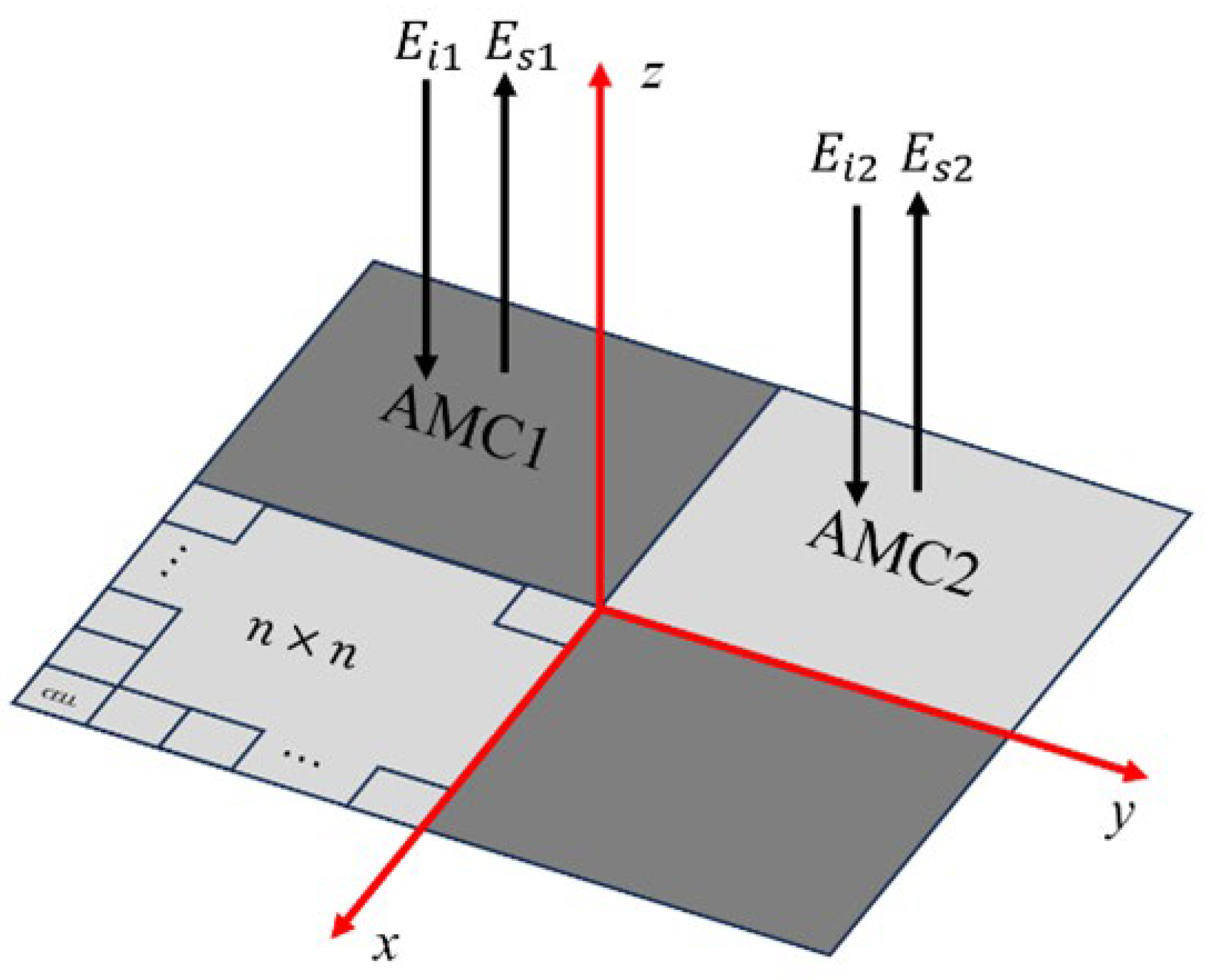
Figure 2.
The Unit Cell Structure. (a)Original Stucture (b)After Rotational Symmetry (c) side view.
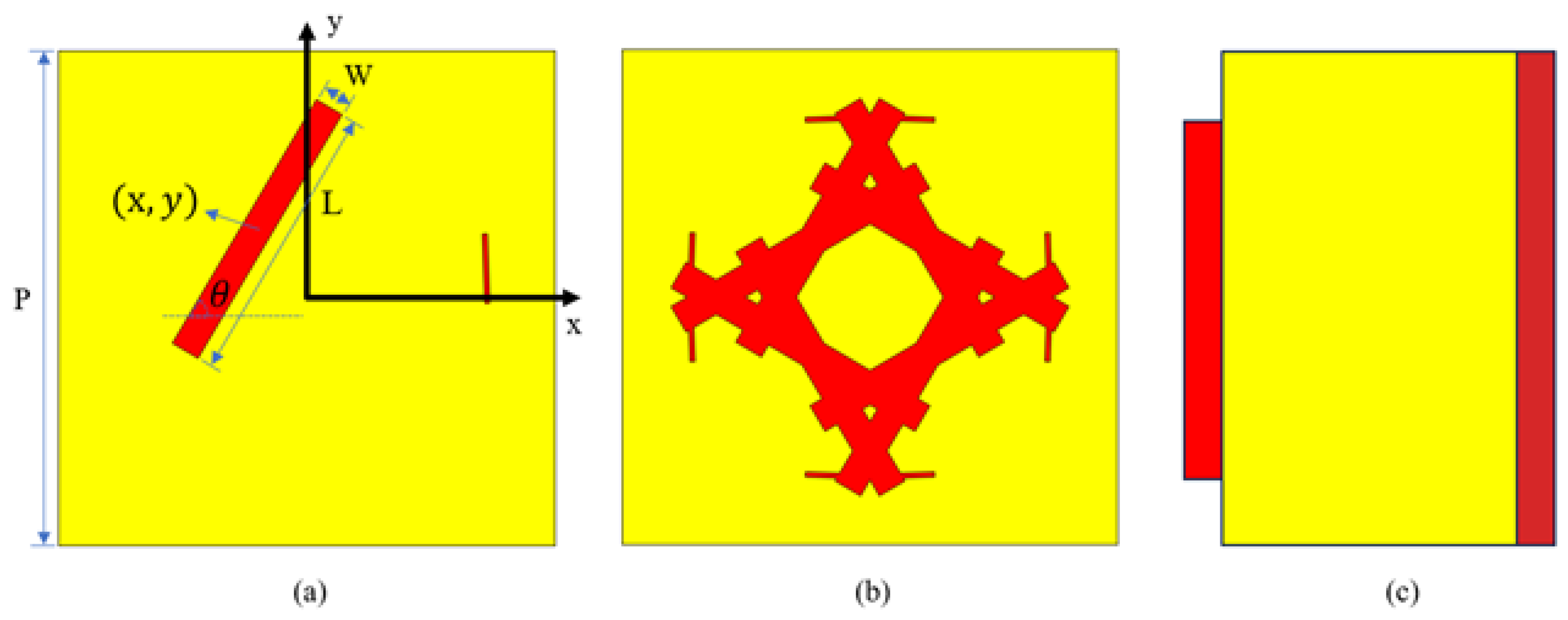
Figure 3.
Flowchart of Cell Pair Optimization.
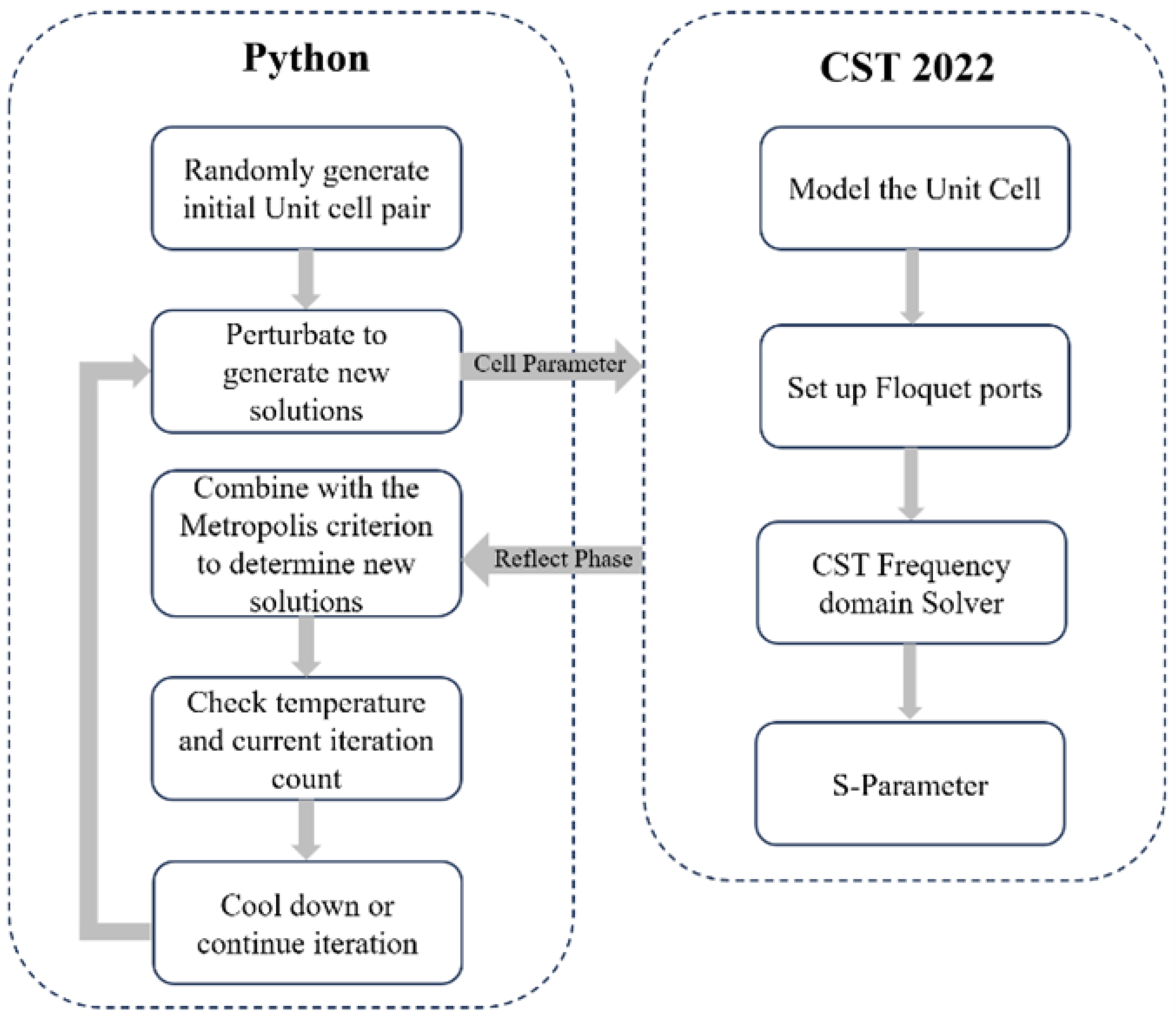
Figure 4.
(a)Reflection Phase of Unit Cell (b)Phase Difference of Two Cells.
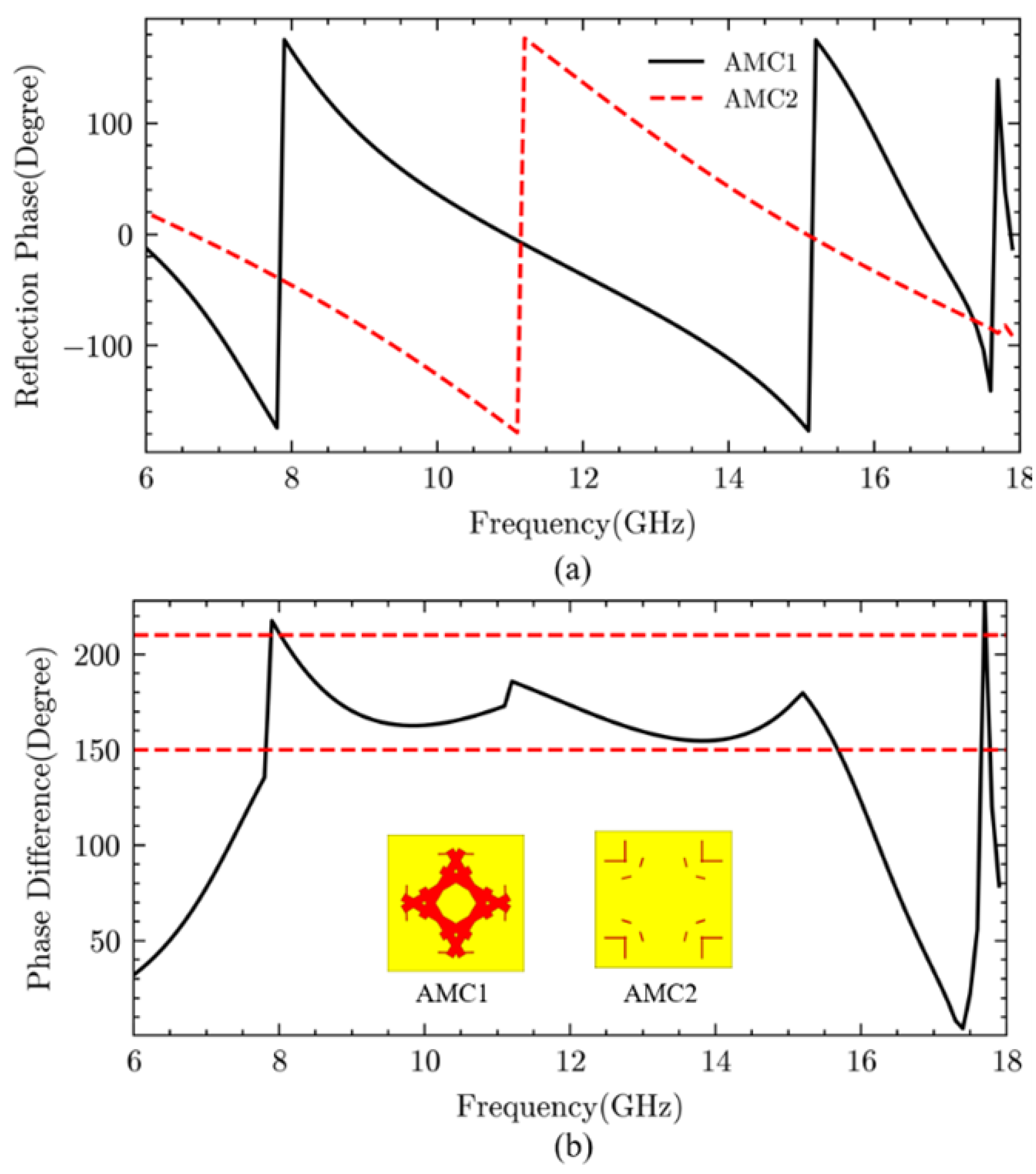
Figure 5.
Full Sturcture of Proposed Chessboard metasurface. (a) CST. (b)Photograph.
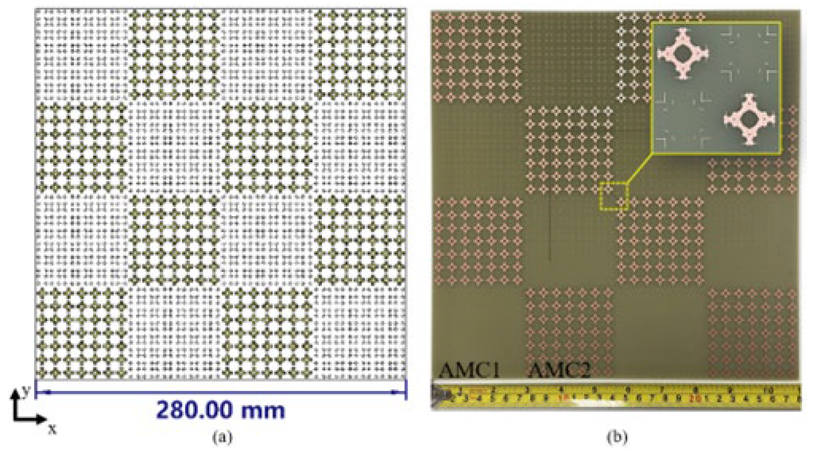
Figure 6.
Surface current distribution of upper layer and ground layer at 5.77, 10.94, 16.7 GHz. (a)-(c) upper layed. (d)-(f) ground layer.
Figure 6.
Surface current distribution of upper layer and ground layer at 5.77, 10.94, 16.7 GHz. (a)-(c) upper layed. (d)-(f) ground layer.
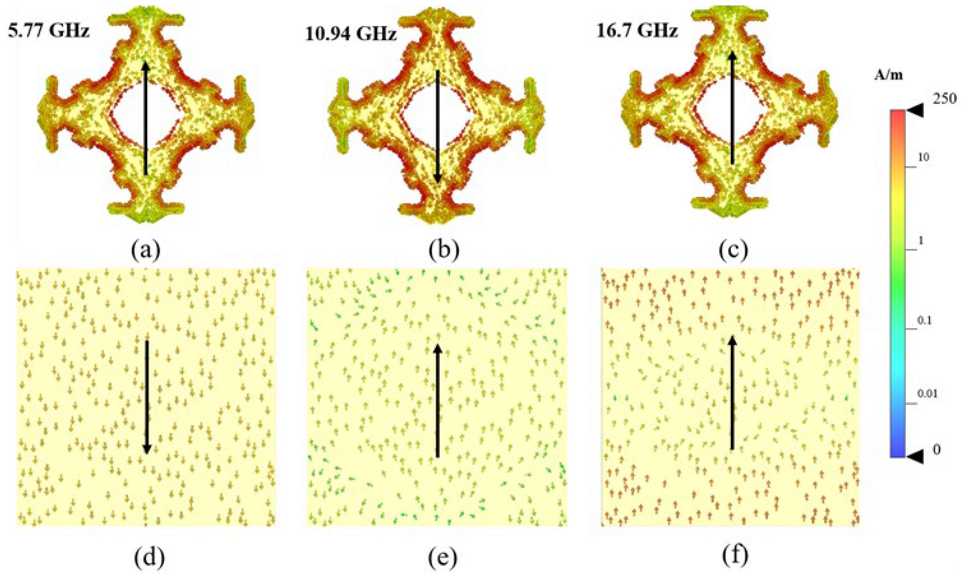
Figure 7.
(a)Block diagram of measurement (b)Measurement Enviroment.
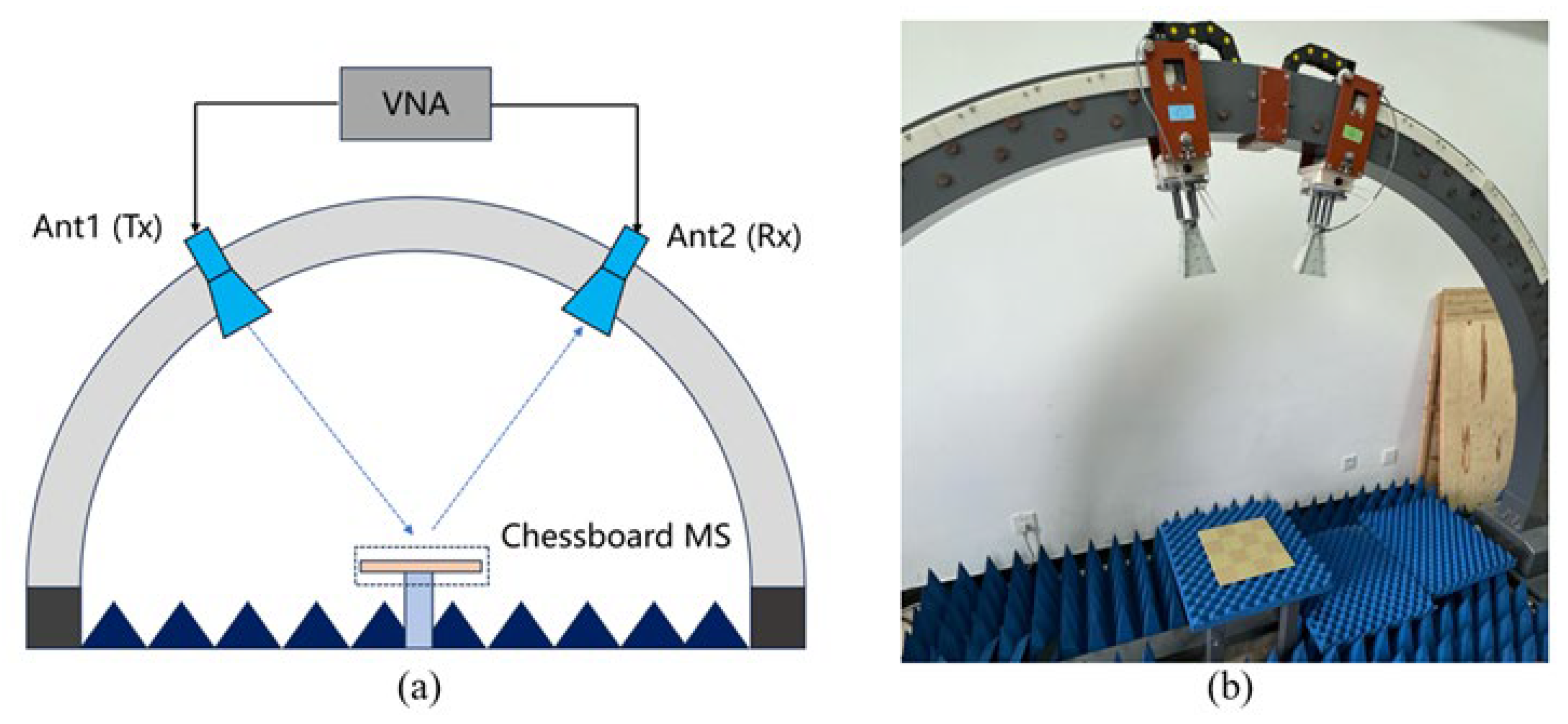
Figure 8.
Monostatic Results of Simulate and Measurement.

Figure 9.
Simulated Monostatic Results in Oblique Incident.
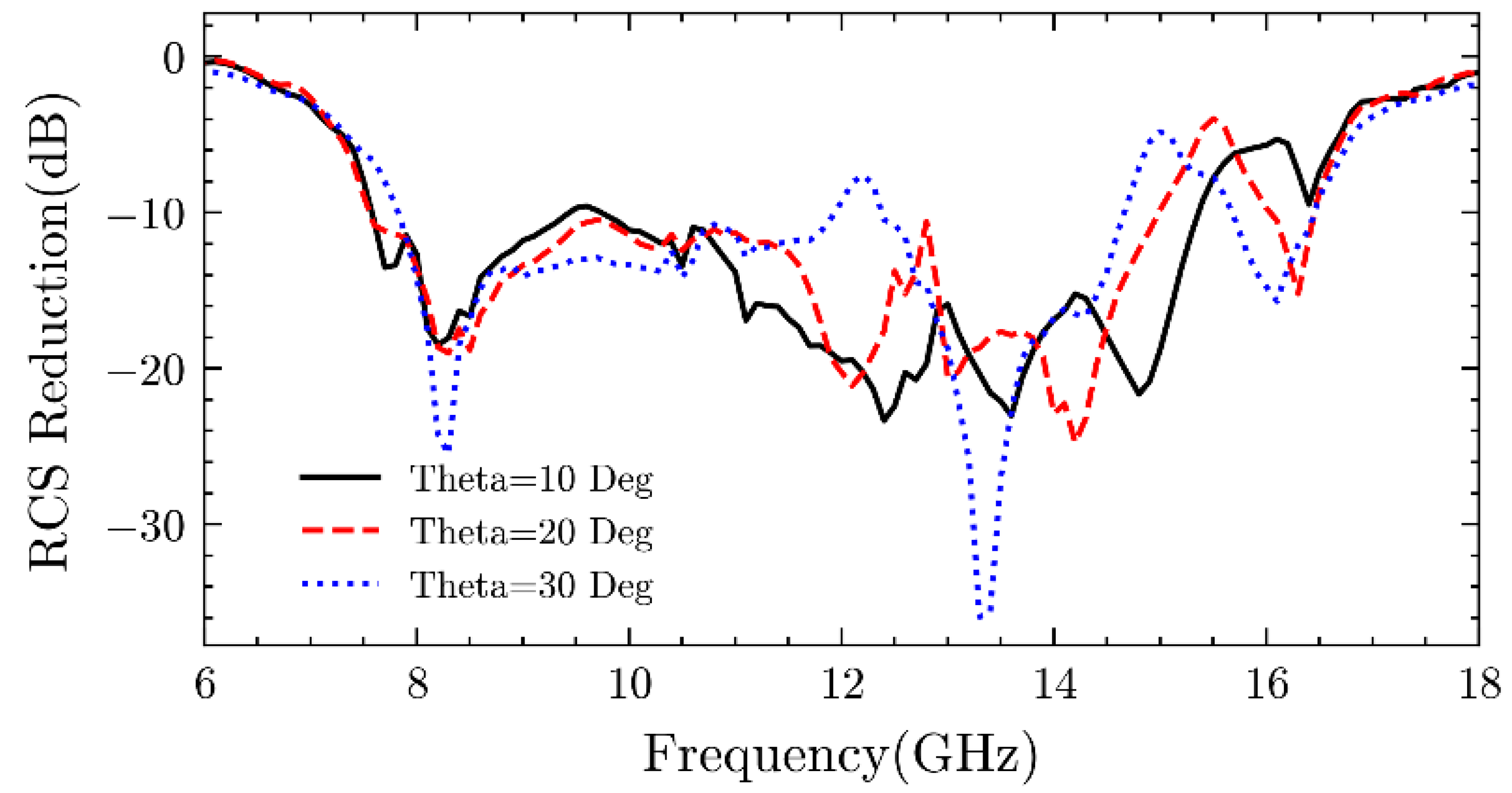
Figure 10.
Simulated 3-D RCS Patterns of metasurface and PEC at 8.4, 12.1 and 14.6 GHz. (a)-(c) Chessboard metasurface. (d)-(f) PEC surface.
Figure 10.
Simulated 3-D RCS Patterns of metasurface and PEC at 8.4, 12.1 and 14.6 GHz. (a)-(c) Chessboard metasurface. (d)-(f) PEC surface.


Table 1.
Geometry Parameter of Optimized Cell Pair.
| x(mm) | y(mm) | W(mm) | L(mm) | Theta(degree) | ||
| Cell#1 | Rec#1 | -1.0 | -1.4 | 0.6 | 5.7 | 30.5 |
| Rec#2 | 3.6 | -0.6 | 1.4 | 0.1 | 87.9 | |
| Cell#2 | Rec#1 | -2.7 | -1.6 | 0.7 | 0.1 | -16 |
| Rec#2 | 2.8 | -3.5 | 1.6 | 0.1 | 90 | |
Table 2.
Comparison Between Other Work. (: wavelength corresponding to the center frequency of the 10-dB reduction band).
Table 2.
Comparison Between Other Work. (: wavelength corresponding to the center frequency of the 10-dB reduction band).
| Ref. | 10-dB RCS reduction BW(GHz, %) | 10-dB RCS reduction BW(GHz, %) of 30° incidence angel | Substrate Thickness | Number of unit cell, Period(mm) |
|---|---|---|---|---|
| [28] | 14.7-22.6/42.3% | 16.6-20.4/20.5% | 0.08 | 2, p=4 |
| [29] | 4.2-7.8/60% | 5.1-6.7/27.1% | 0.13 | 2, p=15 |
| [30] | 7.9-18.2/78% | / | 0.13 | 6, p=8 |
| [31] | 23.7-33.5/34% | / | 0.08 | 2, p=5.8 |
| [32] | 10.8–15.3/34% | 9.3-13.7/38.3% | 0.13 | 6, p =10 |
| [33] | 7.8-23.2/102.7% | 7.1-22.4/103.7% | 0.16 | 10, p=9 |
| [34] | 5.4-7.4/31.3% | 5.7-6.4 | 0.06 | 5,p=2 |
| [35] | 10-20.7/69.7% | / | 0.15 | 4,p=7 |
| This work | 7.6-15.5/68.3% | 7.8-14.6/61% | 0.11 | 2, p=10 |
Disclaimer/Publisher’s Note: The statements, opinions and data contained in all publications are solely those of the individual author(s) and contributor(s) and not of MDPI and/or the editor(s). MDPI and/or the editor(s) disclaim responsibility for any injury to people or property resulting from any ideas, methods, instructions or products referred to in the content. |
© 2025 by the authors. Licensee MDPI, Basel, Switzerland. This article is an open access article distributed under the terms and conditions of the Creative Commons Attribution (CC BY) license (http://creativecommons.org/licenses/by/4.0/).
Copyright: This open access article is published under a Creative Commons CC BY 4.0 license, which permit the free download, distribution, and reuse, provided that the author and preprint are cited in any reuse.


