Submitted:
07 February 2025
Posted:
10 February 2025
You are already at the latest version
Abstract
The global automobile industry faces mounting pressure to develop air conditioning (AC) systems that align with stringent environmental regulations while enhancing vehicle efficiency. Traditional vapor compression refrigeration (VCR) systems are energy-intensive and contribute significantly to greenhouse gas emissions and increased fuel consumption. This paper reviews emerging technologies for automotive air conditioning, emphasizing sustainable alternatives categorized into active, passive, and hybrid systems. Novel developments in thermoelectric cooling, vapor absorption, solar-assisted systems, and hybrid designs are explored. Additionally, the review introduces a comparative analysis of these systems’ performance, focusing on energy consumption, coefficient of performance (COP), and environmental impact. By synthesizing recent research and proposing innovative frameworks, this study offers insights into optimizing sustainable AC technologies for both conventional and electric vehicles, ensuring enhanced passenger comfort and compliance with global environmental standards.
Keywords:
Automotive climate control systems
; climate change
; Air conditioning systems
; GHG emissions
1. Introduction
The rapid growth of the automotive industry has made it a major contributor to greenhouse gas (GHG) emissions, intensifying global warming and climate change. Recent research indicates that annual global CO2 emissions have exceeded 43.2 gigatons, a staggering 20% increase compared to levels recorded in 2013 [1,2]. Although some progress has been achieved in reducing transport-related emissions through electrification, efficiency improvements, and biofuel integration, the sector’s reliance on fossil fuels remains significant. This dependency leads to 24% of CO2 emissions from fuel combustion being released directly into the atmosphere [3]. With nearly one billion vehicles currently in operation worldwide and projections estimating this figure will double by 2035, urgent interventions are necessary to mitigate the escalating environmental impact of this sector[4]. As global temperatures continue to rise, the demand for automotive air conditioning (AC) systems has increased substantially. These systems are essential for maintaining passenger comfort, particularly in regions experiencing extreme heat. However, traditional air conditioning systems are energy-intensive, relying on vapor compression refrigeration (VCR) technology, which uses phase-changing refrigerants to absorb and expel heat. This approach, while effective, imposes significant energy demands on vehicles. In internal combustion engine (ICE) vehicles, this increased workload contributes to higher fuel consumption, whereas in electric vehicles (EVs), it drains battery power, reducing the overall driving range [5].
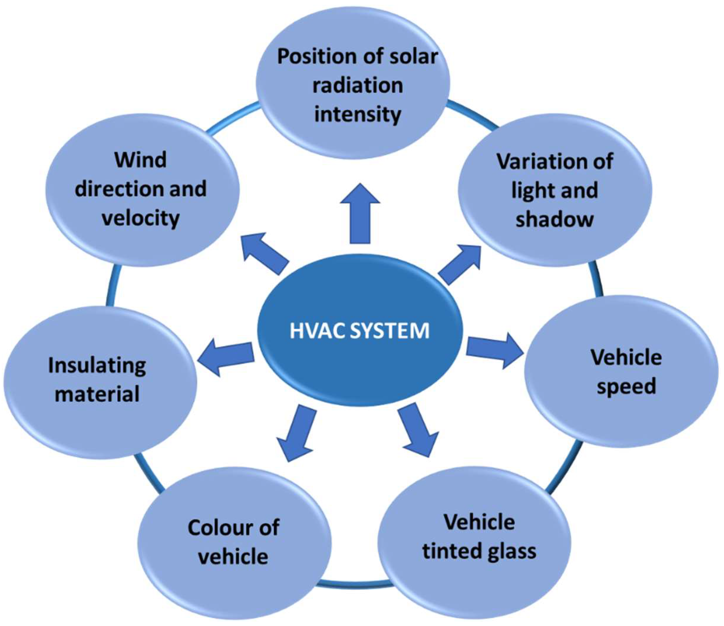
Figure 1.
Factors influence the automobile air conditioning system.
For example, in the United States, approximately 7.1 billion liters of fuel are consumed annually to power vehicle AC systems, emphasizing their environmental and economic costs [6]. VCR systems also utilize refrigerants with high global warming potential (GWP), exacerbating their environmental impact. The widespread adoption of these systems has heightened the need for sustainable alternatives that reduce energy consumption and environmental degradation [7]. In response, the automotive industry is actively exploring innovative technologies aimed at enhancing the energy efficiency and environmental sustainability of AC systems.
In the context of electric vehicles, energy-efficient air conditioning systems are particularly critical. Unlike ICE vehicles, which can utilize engine-generated heat, EVs rely exclusively on battery power to operate their AC systems. This dependency can significantly affect the driving range, with a substantial portion of the battery’s capacity being allocated to cooling demands [8]. Consequently, developing advanced AC technologies that optimize energy consumption without compromising comfort has become a top priority for researchers and manufacturers.
To address these challenges, alternative solutions to traditional VCR systems have been proposed. These alternatives can be categorized into three primary groups: active, passive, and hybrid systems. Active systems include technologies like thermoelectric air conditioning, which employs the Peltier effect for cooling without the need for refrigerants [9]. Passive systems, such as vapor absorption and adsorption technologies, utilize waste heat or renewable energy sources, offering a sustainable alternative to conventional methods are the[10]. Hybrid systems combine active and passive approaches, often incorporating renewable energy sources like solar power and advanced thermal storage solutions to improve overall efficiency [11]. The shift towards low-GWP refrigerants represents another significant development in the effort to enhance the environmental sustainability of automotive AC systems. Traditional refrigerants, such as hydrofluorocarbons (HFCs), contribute significantly to global warming when released into the atmosphere. In contrast, emerging alternatives like hydrofluoroolefins (HFOs) and natural refrigerants such as carbon dioxide (CO2) offer lower GWP values while maintaining cooling performance [12]. These advancements align with international regulatory initiatives, such as the Kigali Amendment to the Montreal Protocol, which aim to phase out high-GWP substances [13]. Despite the promising potential of these technologies, several barriers hinder their widespread adoption. High development and production costs, coupled with the need for substantial infrastructural adjustments, pose significant challenges. Additionally, existing regulatory frameworks often favor established technologies, creating further obstacles for innovative solutions. Collaborative efforts among policymakers, researchers, and industry stakeholders are essential to overcome these barriers and drive the adoption of sustainable AC technologies [14].
This review provides a detailed analysis of recent advancements in sustainable automotive AC technologies, highlighting their advantages, limitations, and potential applications. By examining the interplay between these innovations and vehicle performance, the review seeks to identify pathways for reducing energy consumption and minimizing environmental impact. Particular attention is given to the role of active, passive, and hybrid systems in shaping the future of automotive air conditioning. By synthesizing current research, this review aims to contribute to the ongoing transition toward environmentally sustainable solutions, supporting global efforts to combat climate change.
The subsequent sections delve into the working principles, energy sources, and technological advancements of automotive AC systems, categorizing them into active, passive, and hybrid approaches. This structured analysis provides a comprehensive understanding of the current landscape and the steps needed to foster sustainable innovation in the automotive sector.
2. Working Principle of AAC System:
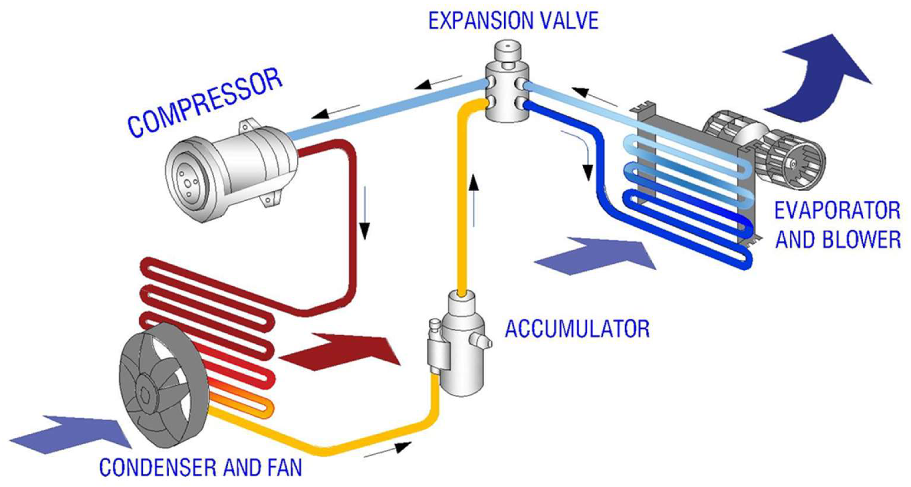
The air conditioning system operates based on the principles of thermodynamic energy conversion and heat transfer. According to the first law of thermodynamics, energy cannot be created or destroyed it can only be transformed. This implies that the energy input, represented by the work performed during compression and the heat absorbed, is equal to the energy output, which consists of the heat rejected to the environment and the work done. The second law of thermodynamics states that heat naturally flows from a hotter body to a colder one. However, external work is required to transfer heat from a colder body to a hotter body [15]. As showed in Figure 2 the air conditioning system utilizes work performed by the compressor to transfer heat from the cooler interior of the cabin to the warmer external environment [16]. The automotive air conditioning system effectively cools the cabin through the continuous cycling of refrigerant in various states, absorbing heat from the interior and releasing it outside. This system employs a refrigerant fluid that circulates through the system, undergoing phase changes between gas and liquid. The refrigerant is compressed by an engine driven compressor, which increases its temperature and pressure before directing it to the condenser. In the condenser, the refrigerant releases heat to the outside air and condenses into a liquid state. Subsequently, the condensed liquid passes through an expansion valve, which reduces the pressure of the refrigerant, causing it to expand and cool rapidly. The cold, low pressure refrigerant then flows over the evaporator coil, where it absorbs heat from the cabin air, this cooled air is then circulated into the cabin by the vehicle's blower fan. This cycle not only lowers the air temperature but also reduces humidity, thereby enhancing passenger comfort [17].
Figure 2.
Automobile Air Conditioning System.
3. Energy Sources for Powering the AAC system
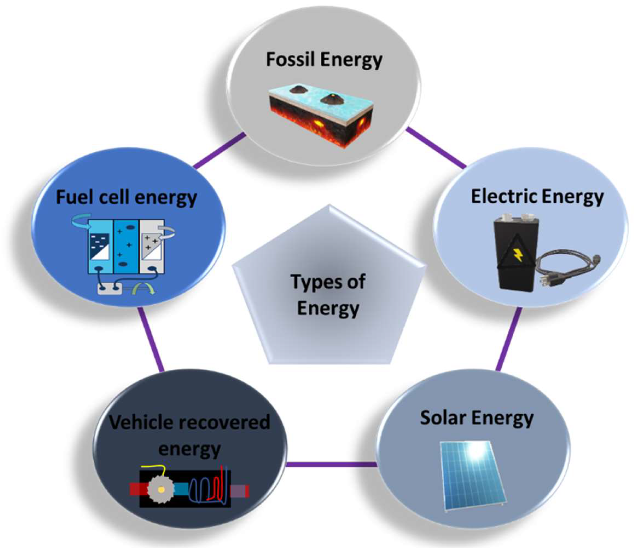
The AAC systems generally rely on the vehicle's engine power for operation. As shown in Figure 3, several energy sources are used for this purpose, including fossil fuels [18], electrical energy [19], solar energy [20], vehicle waste recovered energy [21], and hydrogen and fuel cell energy [22]. Among these, fossil fuels are the most used due to their higher energy density compared to other alternatives.
Figure 3.
Types of energy used for powering the automotive air conditioning system.
3.1. Fossil Energy
Fossil fuels, such as coal, oil, and natural gas, were one of the earliest energy sources used to power engine driven air conditioning systems. Fossil fuels are employed in the AAC system through the fuel that powers vehicle engines, as the majority of vehicles operate on gasoline or diesel, both of which are derived from fossil fuels. Within the engine, the combustion of fuel facilitates the conversion of chemical energy into mechanical energy, which is essential for the operation of the engine. The air conditioning compressor is connected to the engine via a belt driven by the engine's crankshaft. The compressor compresses the refrigerant gas, initiating the refrigeration cycle. This process necessitates energy from the engine, which is powered by fossil fuels [23]. Despite their higher energy density, fossil fuels have significant environmental drawbacks, including greenhouse gas emissions and air pollution [24]. Additionally, fossil fuels are non renewable, meaning their supply is finite and will eventually be depleted, raising concerns about their long term sustainability and availability. These challenges can be addressed through various strategies, including the utilization of alternative refrigerants with lower global warming potential (GWP), the design of air conditioning systems that consume less energy to enhance energy efficiency, the adoption of hybrid and EVs, and the improvement of vehicle insulation to reduce the cooling load on the air conditioning system.
3.2. Electric Energy
Electric energy has gained increasing attention in AAC systems due to its lower environmental impact and the ability to store energy in rechargeable batteries. In electric vehicles, the air conditioning system is powered by the vehicle's battery rather than an internal combustion engine. The battery stores electrical energy, which is utilized to operate the components of the air conditioning system. EVs employ electric compressors instead of traditional belt driven compressors. The electric compressor directly converts electrical energy into mechanical energy to compress the refrigerant, in contrast to conventional systems. This entire process is driven by an electric motor rather than an engine, resulting in enhanced efficiency, particularly during prolonged idling or stop and go traffic, as the air conditioning system operates independently of the engine [25]. Many conventional vehicles have adopted battery powered AC compressors, allowing them to operate independently of the engine [26]. Leading automotive manufacturers, such as BMW and Ford, are developing EVs with AC systems powered by electric energy. However, these vehicles face challenges, particularly the weight of the energy storage systems, which can negatively affect vehicle performance and efficiency. Advances in battery technology are needed to improve the integration of electric energy in automotive applications that yield lighter and more energy dense batteries. [27]. Additionally, exploring ultra capacitors or hybrid energy storage systems can enhance battery performance. Furthermore, designing more compact and lightweight components, such as compressors and evaporators, will help minimize additional weight.
3.3. Solar Energy
Solar energy is a clean and sustainable energy source, and its use in automotive systems, particularly through solar photovoltaic technology, is the focus of ongoing research.
Vehicles are increasingly equipped with solar panels mounted on the roof, which convert sunlight into electrical energy. This energy can be utilized to directly power the electric compressor of the air conditioning system. Additionally, the solar panels can charge the vehicle's main battery, providing a supplementary energy source that can be used to operate the air conditioning system when required [28]. Recent advancements show promise in integrating solar energy into vehicle propulsion and other systems. Researchers at Hong Kong Polytechnic University developed a solar powered AC system for a Coca Cola delivery truck and demonstrated its effectiveness for use in commercial vehicles [29]. This innovative system uses photovoltaic panels mounted on the truck's roof to collect solar energy, which is stored in a battery. The stored energy powers an electric motor that drives a variable frequency driven (VFD) compressor, producing cool air. Notably, this system allows the AC to operate independently of the engine, making it ideal for delivery trucks that often idle during stops. Similarly, Lethwala and Garg et al. [30] installed a solarpowered AC system in a Maruti Suzuki Wagon R, further highlighting the potential of solar energy to enhance vehicle comfort and efficiency. These systems reduce fuel consumption by separating the compressor from the engine and powering it with solar energy. This decreases the engine's workload, improving fuel efficiency and lowering emissions.
However, solar energy systems still face challenges, including the weight of energy storage components and low energy conversion efficiency, which limit their widespread adoption. Addressing these issues is crucial for broader use in the automotive sector. These problems can be mitigated by developing advanced battery technologies that yield lighter and more efficient batteries, thereby reducing weight while enhancing energy density. Additionally, the utilization of supercapacitors can provide rapid bursts of energy for air conditioning operations.
3.4. Vehicle Waste Recovered Energy
Automotive engines are inefficient power converters, losing over 70% of fuel energy during combustion [31]. To address this, researchers are exploring ways to capture and reuse this waste energy. In this system, waste heat energy is primarily utilized in a heat exchanger to preheat the coolant. The heat exchanger is designed to facilitate the transfer of heat between two fluids without allowing them to mix. In this context, one fluid serves as the waste heat source while the other is the refrigerant used in the air conditioning system. Waste heat is contained within the coolant loop, where heat from the engine is absorbed and circulated through the heat exchanger. This process enables the transfer of heat to the refrigerant within its loop. Consequently, the refrigerant is preheated before entering the compressor, thereby enhancing the overall efficiency of the air conditioning system [32]. Several AC systems are being developed that utilize engine waste heat as a power source. Boer et al. [33] designed an AC system that captures engine waste heat, which was successfully implemented in a Fiat Punto. Although effective, further research is needed to improve the system’s efficiency and reduce its size. The amount of recoverable waste energy also depends on various operating conditions, which must be optimized for better performance.
3.5. Hydrogen and Fuel Cell Energy
Hydrogen fuel cells generate energy, either thermal or electrical, by using compressed hydrogen. This technology has gained significant attention, particularly for its potential use in AAC systems. In this system, hydrogen fuel cells generate electricity through an electrochemical reaction between hydrogen and oxygen, producing direct current (DC) electricity. This generated electricity directly powers the electric compressor, facilitating the subsequent processes. The vehicle's control system regulates the power output from the fuel cell to the compressor and adjusts the compressor speed and cooling capacity based on cabin temperature and driver preferences.
Wu et al. [34] developed a hydrogen fuel cell powered AC system for a Toyota Mirai simulation, showing its ability to modulate hydrogen consumption during real driving conditions. Despite its high energy density, which allows for significant energy storage, hydrogen fuel cell technology faces challenges, including system size, cost, and the lack of widespread hydrogen fueling infrastructure. As a result, fuel cell vehicles equipped with AC systems are currently limited to small scale commercialization, and further advancements in technology and infrastructure are necessary for broader market adoption.
4. Recent Developments in cooling Techniques for AAC system
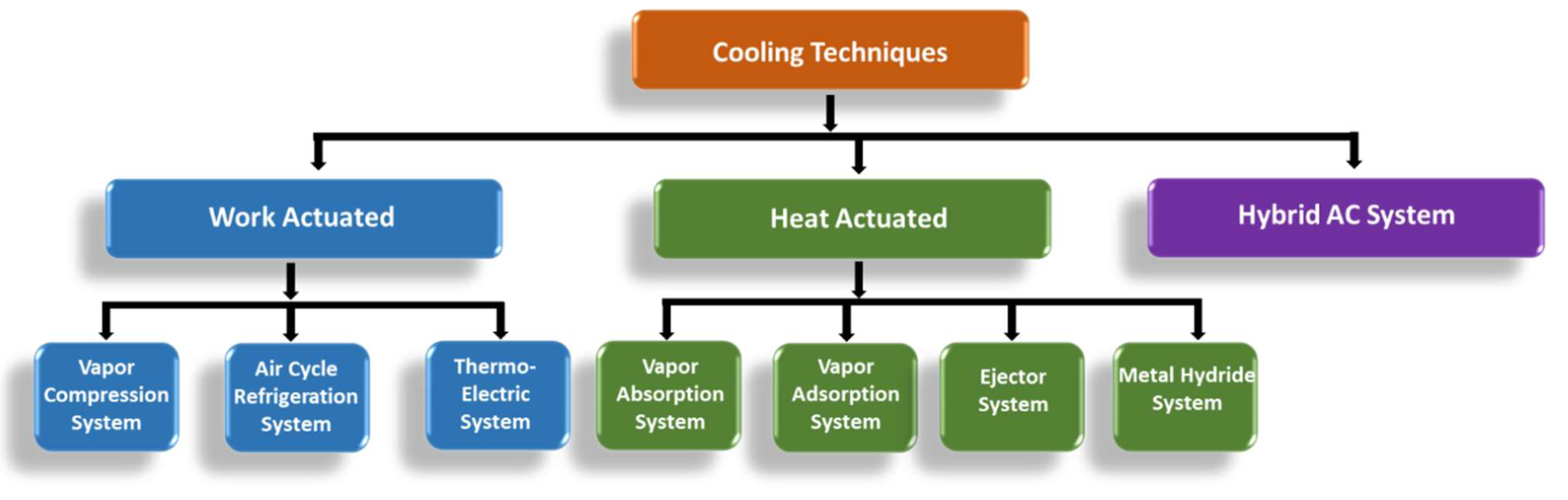
Several alternative cooling techniques have been developed to meet the demand for more efficient and compact AC systems, in addition to traditional vapor compression refrigeration systems as illustrated in Figure 4. These alternative techniques include work actuated (active), heat actuated (passive), and hybrid cooling techniques.
Figure 4.
Types of cooling techniques for automotive air conditioning systems.
4.1. Work actuated (Active) cooling techniques
These work actuated techniques utilize energy that is converted by compressors or pumps into mechanical work to drive the cooling process. Through the integration of different energy sources and advanced technologies, new types of AC systems have been developed. These techniques encompass vapor compression, air compression, and thermoelectric AC systems.
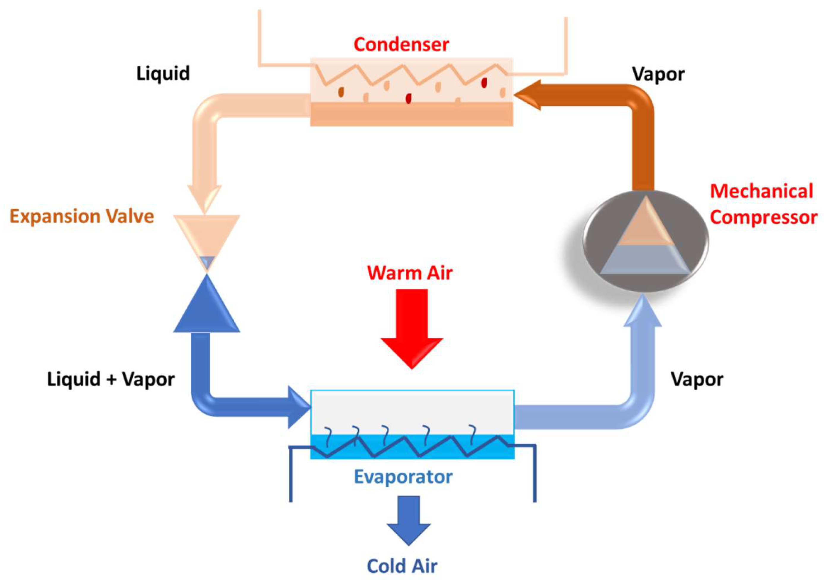
4.1.1. Vapor Compression Refrigeration (VCR) system
VCR is the most traditional and widely used refrigeration system. As shown in Figure 5, the VCR cycle consists of four main components: a compressor, a condenser, an expansion valve, and an evaporator. The cycle's pressure and temperature variations are responsible for the cooling effect. This system in the automotive air conditioning unit operates similarly to a standard refrigeration system, where the compressor is driven by engine power. The compressor compresses the refrigerant and directs it to the condenser, which facilitates the dissipation of heat from the refrigerant to the outside air. Subsequently, the expansion valve reduces the pressure of the refrigerant, causing it to expand and cool. The cooled refrigerant then passes to the evaporator, located within the cabin, where it absorbs heat from the air, thereby regulating the interior temperature [35]. Despite its high efficiency, the VCR system has environmental drawbacks, primarily due to its fuel consumption and the resulting greenhouse gas emissions [4]. Research has focused on improving the VCR system through various techniques such as control and monitoring management [36,37], dehumidification systems [38,39], and optimized system design [40]. These advancements aim to enhance energy efficiency and reduce fuel consumption in AAC systems.
Figure 5.
Illustration of the Vapor Compression Refrigeration System.
Control and Monitoring Management Techniques: This technique helps reduce energy and fuel consumption in AAC systems by optimizing system parameters based on ambient conditions. Maintaining cabin temperature with VCR systems can be challenging due to changing weather conditions. Effective control of system parameters, adapted to the environment, can reduce energy use.
Luger et al. [41] proposed simulation driven optimization approaches for HVAC systems in passenger rail vehicles, offering strategies to optimize operating conditions. They employed Monte Carlo simulations to sample realistic HVAC operating conditions, thereby generating representative data to address the representative operation condition (ROC). Their methodology included multi dimensional signal characterization for enhanced analysis, along with commonly used verification and validation techniques such as sensitivity analysis and desk checking. Recognizing the limitations in system efficiency, recent research by Yin et al. has introduced innovative control strategies to enhance the energy savings and performance of vapor compression refrigeration (VCR) cycles [42]. The researchers developed a novel energy saving control approach that aims to maximize efficiency while meeting the required cooling demand. Through rigorous experimental validation, this control strategy was shown to deliver significant improvements in the overall efficiency and performance metrics of VCR systems. Building on this work, Yin et al. also presented a cascade energy saving control method for integrated vapor compression and refrigeration systems [43]. This approach features an outer control ring that adjusts the superheat degree setpoint based on the current refrigeration capacity requirements. Concurrently, the inner control ring employs model predictive control (MPC) techniques, with its two ends connected to a PI controller and the vapor compression hardware system, respectively. This integrated control architecture enables real time tracking of the system setpoint, leading to enhanced heat transfer efficiency. Subiantoro et al. [44] demonstrated that adjusting the vehicle's internal temperature to higher ranges (20°C–24°C) could save up to 22% of energy and increase the COP by 13%, without additional components [35]. Amri et al. [40] introduced a novel control system for metro vehicles, reducing energy consumption by 325 MWh through thermal simulations. The novel control system is predicated on a demand control strategy, which prioritizes responsiveness to the actual needs of passengers and prevailing environmental conditions rather than maintaining constant HVAC operation. This approach is facilitated through the integration of thermal modeling, data monitoring of CO2 levels, and assessments of energy efficiency. Weng et al [45]. showed that an intelligent energy management system can optimize indoor temperature and humidity to save up to 28% of fuel and decrease compressor load, as seen in Table 1. The system is designed to optimize energy utilization in vehicle air conditioning by continuously assessing real time heat load conditions. It minimizes energy consumption through effective heat load detection and employs a demand controlled strategy that operates the air conditioning system based on actual needs rather than fixed settings, thereby managing both temperature and humidity more efficiently.

Table 1.
Fuel consumption of a car with and without a smart control system.
| Car | Control system | Mileage (Km) | Oil consumption (L) | Specific fuel consumption (Km/L) |
Fuel economy (%) |
|---|---|---|---|---|---|
| A | Without smart control | 121.4 | 9.5 | 12.78 | 24.96 |
| With smart control | 7.6 | 15.97 | |||
| B | Without smart control | 122 | 8.1 | 15.31 | 20.90 |
| With smart control | 6.7 | 18.51 | |||
| C | Without smart control | 120.8 | 9.1 | 12.75 | 28.16 |
| With smart control | 7.1 | 16.34 |
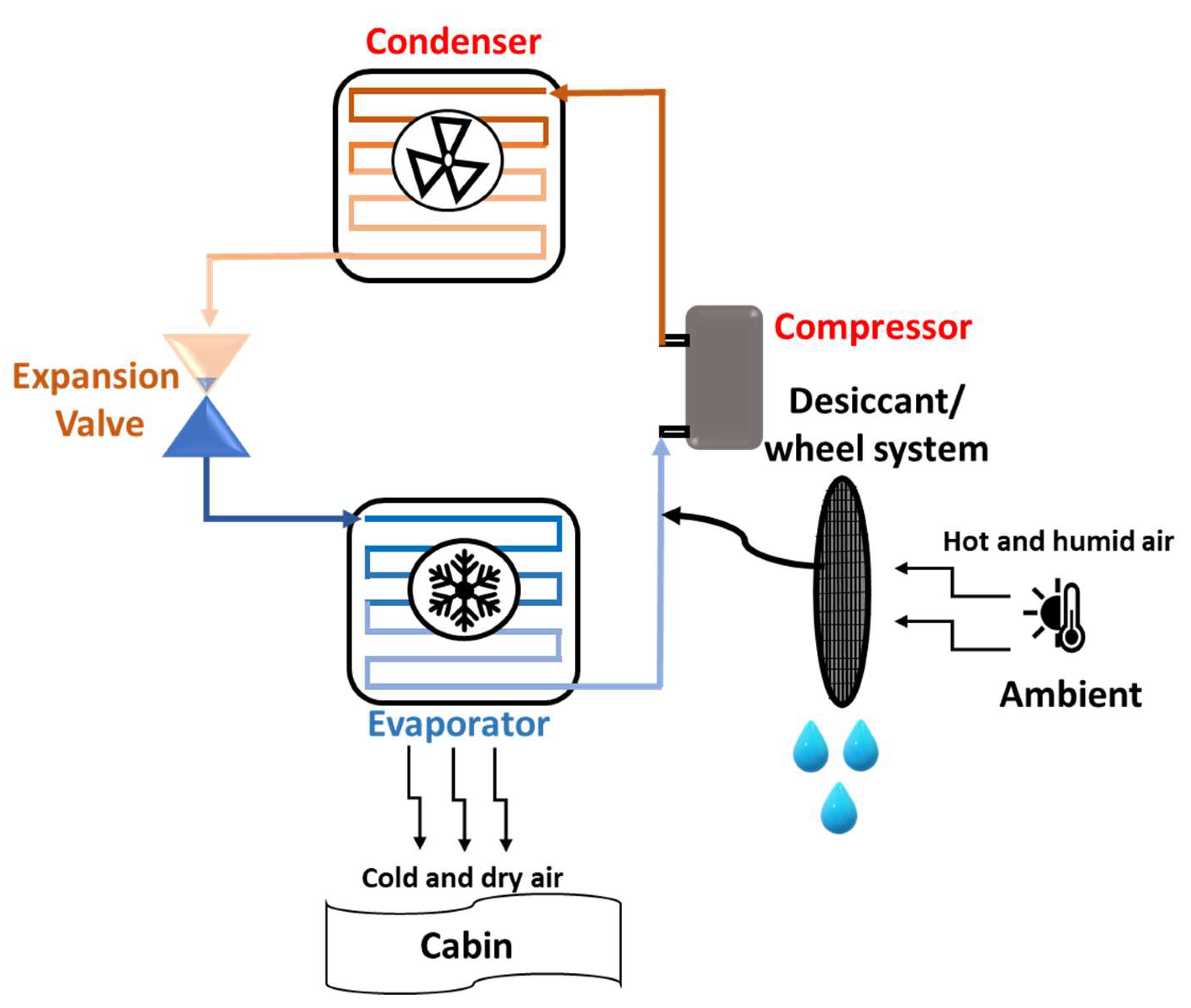
Dehumidification System: Dehumidification is another method to improve AAC system efficiency by controlling temperature and humidity[18] [24]. Using desiccant systems in air conditioners converts humid air into dry air, reducing the overall energy consumption, as shown in Figure 6. Subramanyam et al. [46] demonstrated that an AAC system with a desiccant system reduces the supplied air dew point temperature by 5% and doubles the system's COP compared to traditional systems. Further tests showed that a desiccant system with an optimized wheel speed of 17.5 rotations per hour maximized moisture removal and COP [47]. Nagaya et al. [39] achieved energy savings of up to 26.6% by adjusting the desiccant system's rotation speed up to 900 rpm. Despite these benefits, the system faces challenges such as low efficiency and added weight due to the water tank.
Figure 6.
Illustration of an AC system with a dehumidification system.
Future design improvements aim to address existing drawbacks by developing novel desiccant materials with enhanced absorption capacities and accelerated regeneration rates. Additionally, the exploration of hybrid systems that integrate desiccant technology with alternative dehumidification methods is proposed. The implementation of smart control algorithms that dynamically adjust the desiccant wheel speed and other operational parameters will further optimize performance. Moreover, the design of modular desiccant systems is recommended to facilitate easy scaling within advanced air conditioning systems without necessitating significant modifications.
System Design Optimization: System design optimization can further enhance AAC efficiency by using energy efficient components, such as advanced heat exchangers and electronic expansion valves. Since AAC systems are installed in compact spaces, optimizing design for better performance and lower energy consumption is crucial. Mohamed et al. [48] compared different methods for reducing AAC energy consumption and found out that condenser cooling improved the system's COP by 22.5% and reduced fuel consumption. Chang et al. have developed a specialized HVAC system for electric vehicles, incorporating defogging and dehumidification functions. In air conditioning mode, the system achieved a cabin temperature of 15°C with a COP of 3.18. In heat pump mode, it increased the cabin temperature to 40°C with a COP of 3.3. Notably, the system surpassed the CNS dehumidification standard, achieving 1.47 L/kWh while heating the air to 40°C in the defog heat pump mode. This innovative HVAC solution demonstrates significant advancements in improving the comfort and efficiency of electric vehicle climate control systems [49]. Tang et al. investigated the thermal performance of a vapor compression refrigeration system, utilizing R134a in the primary circuit and an Al₂O₃ water based nanofluid in the secondary circuit, with a focus on dehumidification capabilities and energy efficiency [50]. The results show that the Total Dehumidification Capacity (TDC) decreases with increasing air temperature but increases with higher humidity, peaking at 6.62 kg/h at 80% relative humidity and 26°C. Notably, the PCPDC, representing energy efficiency, improves with higher humidity, reducing from 3383.48 kJ/kg at 38% humidity to 1286.5 kJ/kg at 80%. The researchers also identified an optimal airflow rate for maximizing dehumidification efficiency, which varies depending on the humidity level.Yu et al. [51] analyzed the performance of a microchannel heat exchanger and found improvements in heat transfer and airflow efficiency. The objective of the microchannel heat exchanger is to investigate and enhance the thermal performance characteristics of the air conditioning heat pump system. This focus is directed towards improving heat transfer efficiency by analyzing airflow dynamics and optimizing design parameters. Subiantoro et al. [44] introduced a methodology to evaluate the performance of air conditioning systems utilizing different refrigerants, specifically R134a and R1234yf. The thermal loads within the vehicle cabin were modeled based on factors such as solar radiation, body heat generated by passengers, and heat emanating from the car body with a 10°C temperature difference between the evaporator and condenser, increasing COP by 45% and reducing energy consumption by 30%. However, further research is needed for better heat exchanger designs. Kapoor et al. [52] evaluated the performance of reciprocating and scroll compressors, showing that scroll compressors improved COP by 18.8%–25.3%, reducing power consumption in AAC systems. The fuel and energy consumption of the AAC system can be reduced through system design optimization. However, the design should be lightweight and small without increasing the overall product cost.
4.1.2. Air cycle refrigeration system
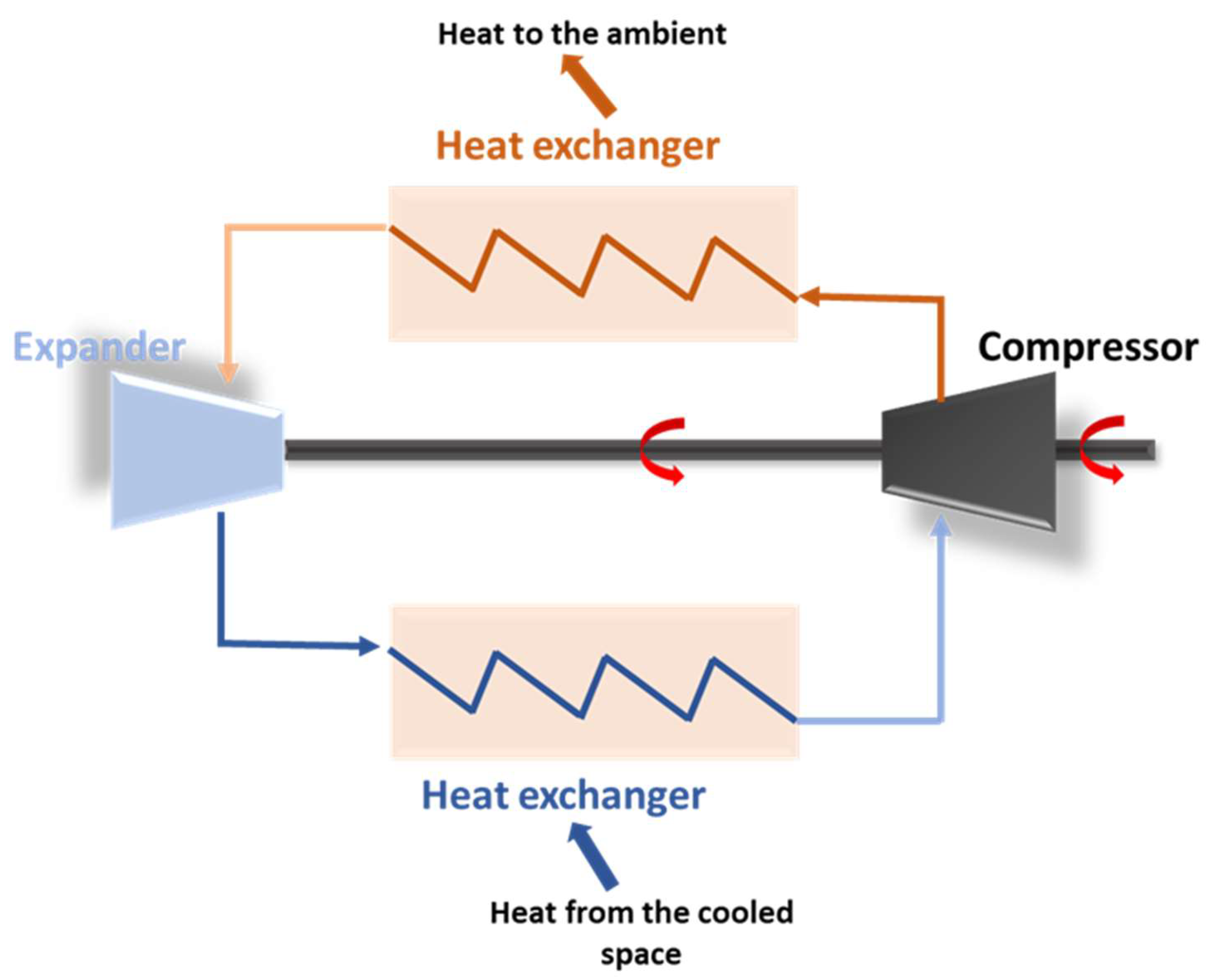
Air cycle refrigeration (ACR) systems, also known as the R729 system, operate on the reverse Brayton cycle and are primarily used for cooling in aviation. These systems use air or other gases as the working fluid, circulating in a closed cycle without phase changes to produce the cooling effect. An illustration of the ACR systems design is shown in Figure 7. In the air cycle refrigeration system, ambient air is drawn into the compressor, where its pressure and temperature are increased before being directed to the condenser. In the condenser, the air releases heat to the external environment while maintaining high pressure. The air then passes through the expansion valve, where both pressure and temperature are rapidly reduced. Subsequently, the low pressure, low temperature air enters the evaporator, which absorbs heat from the cabin air, thereby cooling the interior environment [53]. Air as a working fluid is abundant and is an environmentally friendly option with zero ozone depletion potential (ODP) and GWP. Additionally, ACR systems are lightweight and compact. Recent research indicates that air cycle refrigeration technology can greatly enhance fuel efficiency in AAC systems. Although commonly used in aircraft air conditioning, these systems have not been integrated into automobile AC systems due to the widespread synthetic refrigerant usage. However, recent studies have demonstrated potential for their application in automobile AC systems, particularly in light of environmental concerns related to synthetic refrigerants [41], [42], [43], [44].
Figure 7.
Illustration of the Air Cycle Refrigeration System.
Shengjun et al. [54] found that the COP of ACR systems is influenced by factors such as pressure ratio and inlet temperature, with system performance relying heavily on the isentropic efficiency of the compressor and expander. Zhang et al. [55] implemented the ACR systems in Chinese trains, reporting a COP between 1 and 1.2, with supplied air temperatures of 1°C to 6°C. They highlighted the potential for improvement through more efficient components, like compressor expanders and heat exchangers.
Yang et al. [56] conducted a comprehensive investigation into the thermodynamic performance of air refrigeration cycles in compartment air conditioning systems, examining both closed loop and open loop configurations. Result shows that the open loop high pressure cycles exhibited significantly higher coefficients of performance (COP) compared to the low pressure cycles. Furthermore, the recycling of condensed water was shown to improve the maximum COP by up to 48.8%, highlighting the potential for enhanced energy efficiency. Notably, the system demonstrated effective performance under varying ambient conditions, such as high altitudes, while maintaining comfortable air pressure and temperature level.
Spence et al. [57], [58] conducted a thermodynamic analysis of ACR systems for road transport, finding higher fuel consumption than VCR systems under full load. However, under partial load, air cycle systems reduced fuel consumption by up to 80%, with a 35% reduction in overall power consumption.
Efforts to utilize recovered exhaust energy for air cycle systems have also been explored. Foster et al. [59] developed and tested an air cycle system. The system used a turbocharger driven by the exhaust gas of an automobile achieving a peak COP of 0.73 for a cooling capacity of 1.5 tons, though overall efficiency was still low. Mahajan et al. [60] developed an air cycle system for truck cabin cooling, using a turbocharger to extract energy from exhaust gas, compress air, and cool it via a heat exchanger. Their system achieved a temperature reduction of 10°C to 15°C in the truck, showing that air cycle refrigeration can be implemented without sacrificing performance, energy efficiency, or fuel consumption
While ACR systems offer environmental advantages, such as reducing ODP and GWP, challenges remain, including bulky and costly components like compressors and turbines. Ongoing research aims to optimize system performance through advanced turbomachinery and turbochargers, positioning air cycle systems as a viable alternative to VCR systems in the future.
4.1.3. Thermoelectric System
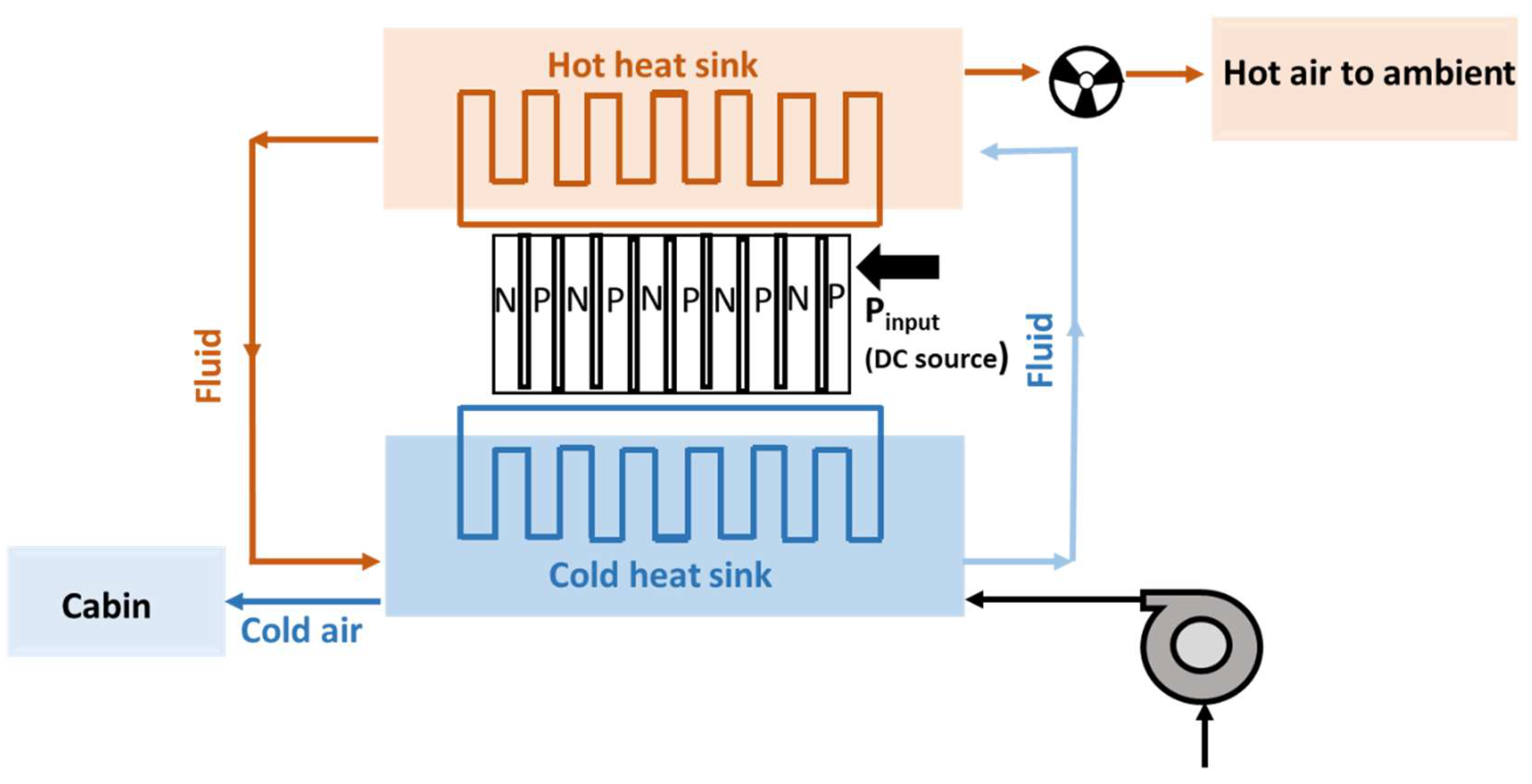
A thermoelectric air conditioning (TEAC) system works based on the Peltier effect, which requires electrical energy to function. This makes it an active, or work actuated, AC system. The only moving part in the system is a pump that circulates the working fluid. Figure 8. shows the basic layout of a TEAC system. In this system, a thermoelectric module comprises two semiconductors (p type and n type) connected electrically in series and thermally in parallel. When DC is applied to the module, electrons migrate from the n type semiconductor to the p type semiconductor, resulting in the establishment of a temperature differential. The cold side of the thermoelectric module absorbs heat from the surrounding environment, thereby cooling the surface and enabling it to extract heat from the cabin air. Conversely, the hot side of the thermoelectric module dissipates the absorbed heat to the environment via a fan that circulates air over a heat sink, thus perpetuating the cycle [61]. While TEAC systems have a quick cooling response, their efficiency and overall performance depend on the temperature difference across the thermoelectric cooler. Due to increasing concerns about environmental impact and energy consumption, many studies have explored the use of TEAC systems in AAC systems [62], [63,64].
Figure 8.
Illustration of the Thermoelectric air conditioning System.
Yogesh et al. [65] and Patil et al. [66] explored the potential of a thermoelectric module system based on the Peltier effect as a replacement for the conventional car air conditioning system. The researchers integrated the thermoelectric system with the blower of a Maruti Suzuki Zen and equipped it with a temperature controller. The experimental results demonstrated that the thermoelectric system was capable of reducing the ambient temperature by up to 7°C, without the need for compressors or refrigerants. This compact, quiet, and eco friendly alternative to traditional air conditioning systems proved to be a feasible solution, offering a promising approach to address the limitations of conventional car climate control technologies. Attar et al. [67], [68] conducted both experimental and analytical studies to optimize the design of TEAAC systems. Their research found that the optimized TEAAC system achieved a COP 30% higher than that of conventional air conditioning systems. They also studied a counterflow air to TEAAC system and found that the experimental and predicted COP values differed by only about 4.5%. The system reached a COP of 1.27 with a 400W power supply [69]. In another study, Chen et al. [70] designed and implemented a TEAC system for elevator cars. Compared to conventional AC systems, which typically weigh around 38kg, the new TEAC system weighed only 10kg. This system achieved a COP of 1.24 with a maximum cooling capacity of 324W. Given the concern over fuel and energy consumption in vehicles, researchers have increasingly focused on using waste exhaust energy. Thermoelectric generators (TEGs) have gained attention as a promising solution for reducing fuel use. Ran et al. conducted experiments to integrate TEGs with an air conditioning system [71]. They tested three scenarios: one with a standard AC system, one with a TEG added, and one where the AC system was powered by the TEG. Fuel consumption over a 100 km distance was 35.6 liters, 34.8 liters, and 34.28 liters, respectively. These results suggest that TEG systems can save up to 2.24% in fuel, and using TEG powered air conditioning can achieve up to 3.71% savings.
Several car manufacturers have also developed air conditioning systems using TEAC technology. Amerigon Corporation introduced the Amerigon Peltier Modules Climate Control System (CCS), a thermoelectric AC system designed to cool and heat car seats, providing personalized climate control for the cabin [72]. Raut et al. [62] developed and tested a thermoelectric AC system in the Maruti Suzuki Zen, showing that while the system was feasible, improvements in COP and system size were needed [49].
The research shows that TEAC systems offer several advantages, including reducing dependence on harmful refrigerants. They can target specific areas for cooling rather than cooling the entire cabin and easily switch between cooling and heating modes. The compact design is another benefit, as TEAC systems have no moving parts. However, the COP of these systems is highly dependent on the temperature difference across the thermoelectric heat pump, meaning further research into advanced thermoelectric materials is needed to improve energy efficiency and reduce fuel consumption.
4.2. Heat Actuated (Passive) AC System
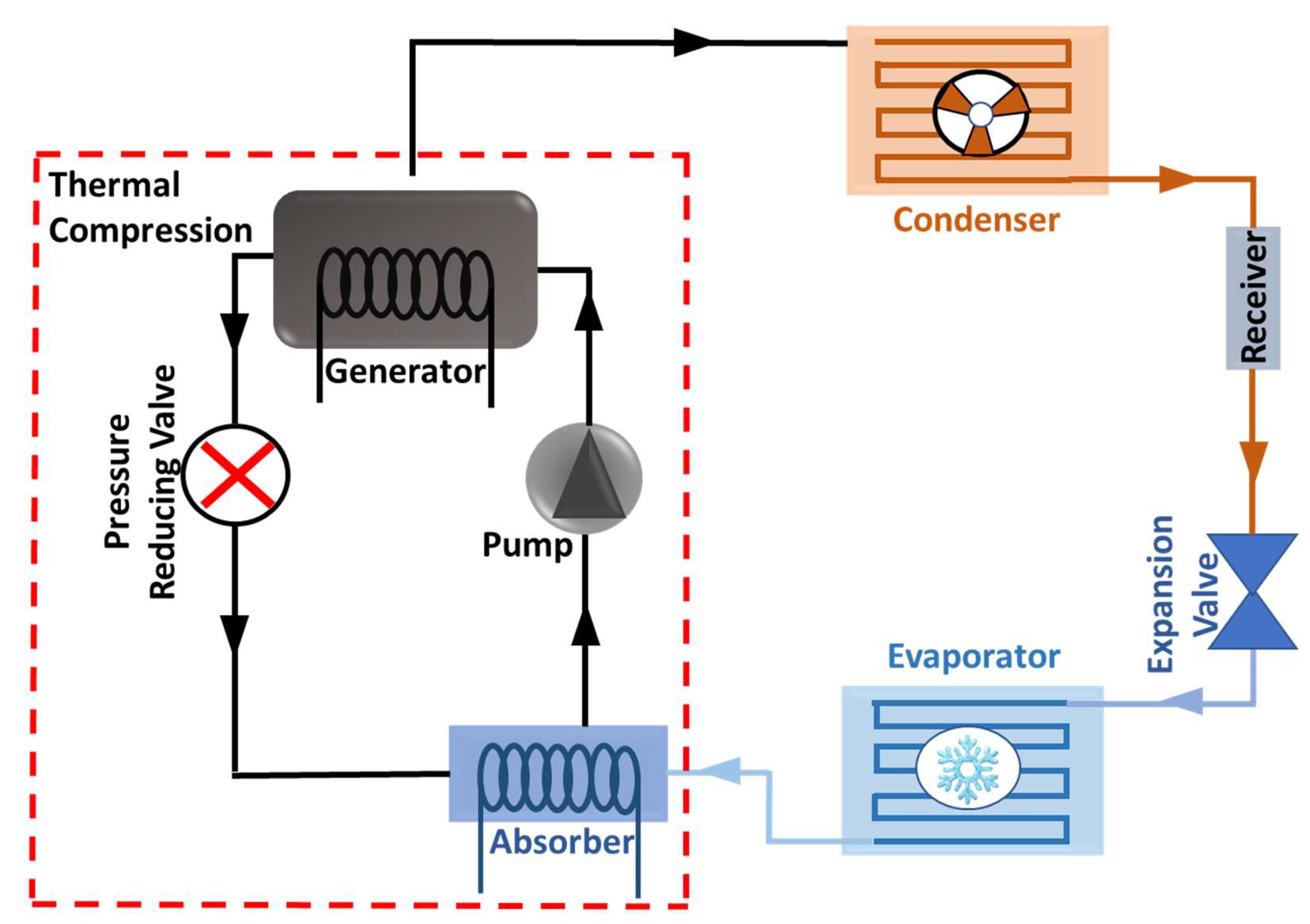
A heat actuated, or passive, air conditioning system utilizes thermal waste or surplus energy to drive the thermal compression of refrigerants. This system is distinguished by its lack of moving parts, except for the pump. Passive air conditioning (PAC) systems are categorized into four main types: vapor absorption systems [73], [74], vapor adsorption systems, ejector systems, and metal hybrid systems. Current research in this field highlights the potential of PAC systems as an effective solution for utilizing waste and excess heat.
4.2.1. Vapor Absorption System
Vapor absorption Refrigeration systems (VARS) are powered by thermal energy and, as shown in Figure 9, use an absorber and a generator instead of a compressor. This system comprises five main components: the absorber, generator, condenser, expansion valve, and evaporator. In this process, the refrigerant, commonly ammonia, enters the absorber in vapor form. The vapor is absorbed into a liquid absorbent, typically water, resulting in the formation of a concentrated solution. This concentrated solution is then pumped to the generator, where it is heated using an external heat source. Upon heating, the refrigerant vapor is released from the absorbent, leaving behind a weak solution. The vapor subsequently passes to the condenser, where it is cooled by air or water, condensing back into liquid form while releasing heat to the external environment. The high pressure liquid then flows through the expansion valve, which reduces its pressure, leading to a rapid temperature drop. This low pressure, low temperature fluid then enters the evaporator, where it absorbs heat from the cabin air, thereby cooling the interior environment. The remaining absorbent solution returns to the absorber, allowing the cycle to repeat [75].
VARS are primarily used in refrigerated trucks. These systems work by thermally compressing refrigerants through the absorption of a vapor fluid into a carrier fluid. In this process, the vapor fluid acts as the sorption material, and the carrier fluid serves as the refrigerant. However, they typically rely on refrigerants with a high GWP and consume significant amounts of fuel which is about 40% of the vehicle's total fuel consumption [8].
Figure 9.
Illustration of the Vapor absorption air conditioning system.
Tassou et al. [76] investigated alternative air conditioning systems for refrigerated trucks aimed at reducing energy and fuel consumption. They discussed several options, including sorption systems utilizing engine reject heat, air cycle refrigeration, and thermal energy storage. Their findings indicated that harsh operating conditions could reduce the COP to between 0.5 and 1, suggesting that conventional truck refrigeration systems are inefficient and environmentally detrimental. In response, Venkatraman et al. [77] reviewed VARS powered by engine or fuel cell exhaust gases and concluded that reducing the system's size and weight, along with using microchannel heat exchangers, could improve performance. Although VARS generally have a low COP, they provide significant cooling capacity, and incorporating fuel cells into the system could further reduce fuel consumption. Pandya et al. [78] compared two solid oxide fuel cell configurations (the series and the parallel configurations) coupled with VARS to assess efficiency. They found that the parallel layout was more efficient, reducing fuel cell capacity requirements by 45 65% compared to the series layout, and cutting CO2 emissions by 5 30%. A substantial amount of thermal energy is lost through engine exhaust gases, which can serve as a valuable energy source for powering absorption air conditioning systems. Numerous studies have focused on designing systems that use exhaust gas for absorption air conditioning, with several prototypes undergoing testing.
Wang et al. [79] developed and tested an ammonia water vapor absorption refrigeration system, which achieved a cooling capacity of 2 kW and cabin temperatures as low as 6°C. However, spatial constraints posed challenges. Similarly, Shekhar et al. [80] simulated an ammonia water vapor absorption system for cooling truck cabins, but reported a low COP (0.3528 0.3113) despite sufficient exhaust heat to power the generator.
Shah et al. [81] proposed a model using ammonia, water, and hydrogen for a one ton air conditioner. They found that exhaust gases provided enough thermal energy for the air conditioner across various engine speeds, but noted concerns about ammonia toxicity and the system's bulkiness. Multerer et al. [82] highlighted two primary concerns with using ammonia: its toxicity, which poses health risks if leaks occur in the passenger compartment, and inadequate power generation when engines become smaller and more efficient. AlQdah et al. [8] designed an absorption based AC system utilizing thermal energy from exhaust gases, achieving a COP of 0.85 1.04 and a cooling load of 1.37 TR.
From these studies, it can be concluded that VARS using exhaust gases for thermal energy can enhance cooling capacity while reducing emissions, operating costs, and overall fuel and energy consumption. In comparison to conventional VCR systems, VARS offers several advantages:
Economic benefits due to reduced manufacturing costs through high precision system components.
Environmental advantages, as ammonia has minimal negative atmospheric effects.
Lower energy consumption: VARS require less fuel compared to conventional VCR systems.
However, applying VARS in automobiles still faces challenges, including large system size, low COP, and ammonia toxicity. Therefore, future research is needed to improve system performance by identifying more efficient absorbents/refrigerants and finding ways to reduce system size.
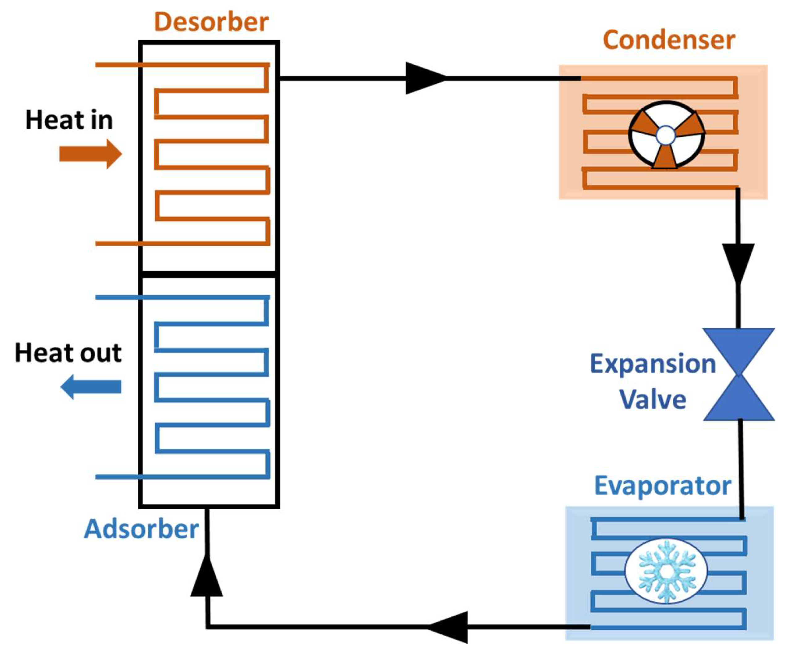
4.2.2 Vapor Adsorption System
The vapor adsorption system shows great potential in various practical applications, especially when combined with Vapor Absorption Refrigeration Systems. This system uses a combination of fluid and solid materials, where the solid acts like a sponge, absorbing and desorbing large amounts of refrigerant fluid. The system’s efficiency depends heavily on the choice of the solid fluid pair. Additionally, the system requires thermal energy in the adsorber to increase pressure through a process known as thermal compression. The cooling effect of this system is achieved in four distinct stages: pre heating, desorption, pre cooling, and adsorption [83], [84]. As shown in Figure 10. the refrigerant vapor enters the adsorber, where it is adsorbed by a solid adsorbent. As the vapor is adsorbed, it extracts heat from the cabin air, resulting in a decrease in interior temperature. Concurrently, the adsorbent becomes saturated with the refrigerant, storing the absorbed heat. The adsorbent subsequently releases the adsorbed refrigerant vapor by applying heat in the desorber. This heat can originate from various sources, such as waste heat or an external heating element. The released refrigerant vapor then moves to the condenser, where it is cooled by air or water, transitioning back to a liquid state while releasing heat to the external environment. The liquid refrigerant then passes through the expansion valve, which reduces its pressure, leading to a rapid temperature drop. The low pressure, low temperature refrigerant subsequently enters the evaporator, where it absorbs heat from the cabin air, thereby cooling the interior once again. This cycle repeats as the adsorbent returns to the adsorber to absorb additional refrigerant vapor, thereby maintaining the cooling effect[85].
A key advantage of this system is its ability to utilize waste heat from engines or other renewable energy sources, which drives the cooling process. Lim et al. [86] proposed an adsorption AC system powered by exhaust gas, reporting a COP of 0.19 and a specific cooling power of 396.6 W/kg. The cooling coil temperature ranged from 9.5°C to 14.7°C, while the cooled air temperature varied between 20.7°C and 25°C. Similarly, Jiangzhou et al. [87], [88] studied an adsorption AC system using engine exhaust gases and a zeolite water pair for locomotive driver cabins, finding a cooling capacity of 5 kW with an outlet air temperature of 18°C. They suggested that improvements in evaporator design could significantly boost system performance, particularly cooling capacity.
Figure 10.
Illustration of the Vapor adsorption air conditioning system.
In the TOPMACS project, Robert et al. [33] developed and tested an adsorption AC system installed in a Fiat Punto. They reported a COP of 0.3 to 0.5 under steady state conditions. The compact design allowed the system to fit into the engine bay, although its peak cooling power fell short of the required performance standards. In the context of EVs, Aceves et al. [14] analyzed an adsorption system to check if the system can be applicable for AC in EVs and found it to be 25% heavier and more space consuming than conventional vapor compression (VC) systems. With a low COP of 0.28, they recommended developing new absorbents to improve heat transfer efficiency. Abdullah et al. [42] explored the possibility of employing a solar powered adsorption system for the AAC system that demonstrated its capability to maintain comfort by regulating temperature in vehicles both while driving and parked.
Activated carbon is commonly used as an adsorbent in many systems, in absorption air conditioning systems, activated carbon is employed as a sorbent to absorb water vapor, thereby facilitating both dehumidification and purification processes but its production can be expensive. As an alternative, oil palm shells can be used to create activated carbon. Abdullah et al. [90] applied this material in an adsorption system for automotive air conditioning, yielding a low COP of 0.5 to 0.8 and limited cooling capacity due to the low latent heat of the adsorbate.
Jiang et al. [91] proposed a sorption AC system to reduce electricity consumption in EVs, which resembled conventional vapor compression systems but with a sorption reactor replacing the compressor. The system used sorbents derived from natural graphite, reporting COP values from 0.34 to 0.82 in winter and 0.19 to 0.42 in summer. They recommended integrating the battery cooling system with the sorption AC system to enhance energy efficiency. Lu et al. [92] assessed an adsorption AC system with a built in adsorber and cold storage, achieving a cooling power of 3.3 kW and a COP of 0.25, with increased cooling capacity through improved generation processes.
An ideal AAC system should be compact and deliver optimal cooling. While using thermal energy from automobile exhaust gases is effective, it often increases the system’s weight and space requirements, complicating the design and implementation. Therefore, developing streamlined and efficient designs is crucial to overcoming these challenges.
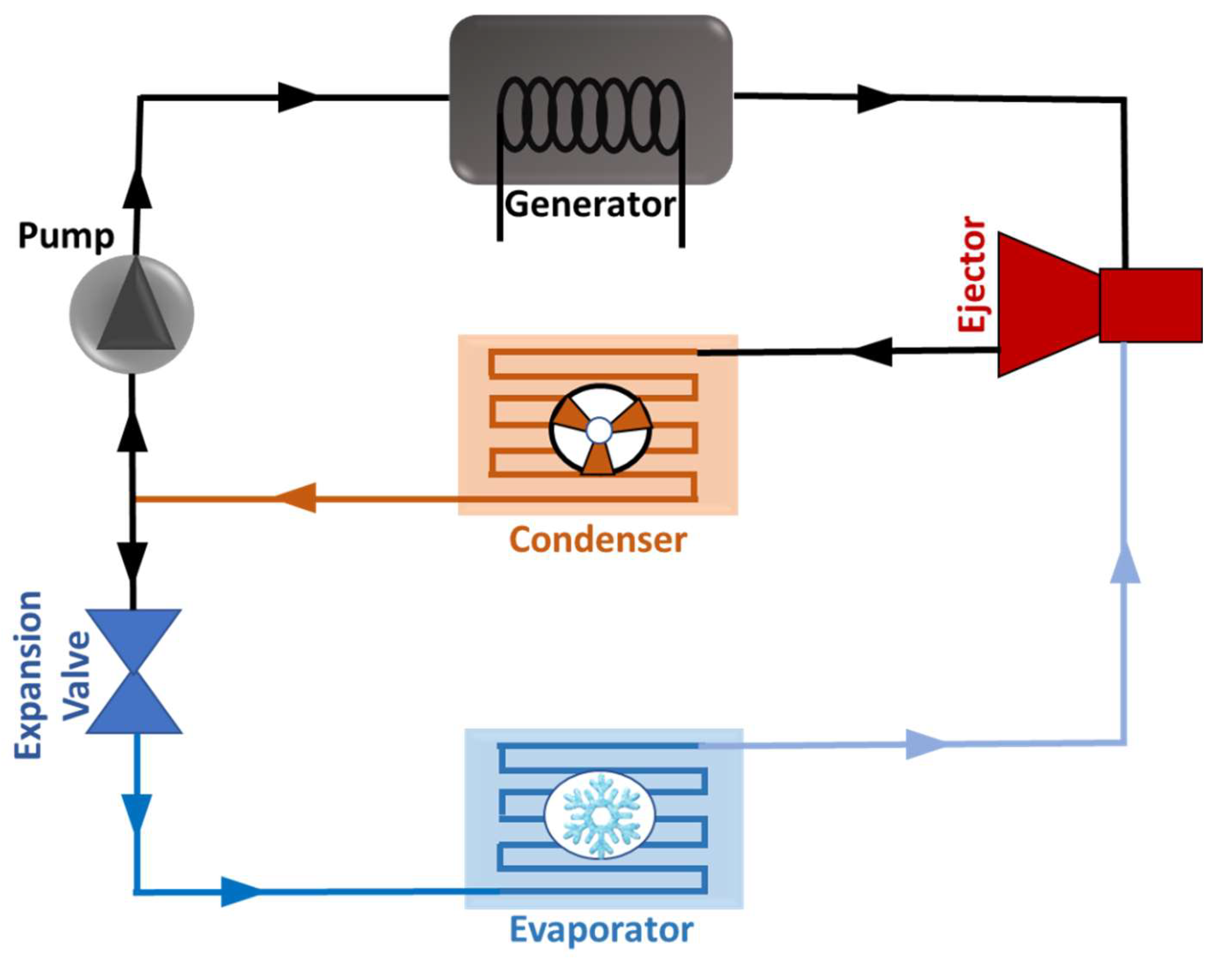
4.2.3 Ejector System
In AAC systems, the ejector system is a variation of the VCR system, using an ejector instead of a conventional compressor. This system operates with both high pressure and low pressure refrigerant circuits. The cycle, as illustrated in Figure 11. commences with the evaporator, where the refrigerant absorbs thermal energy from the vehicle's cabin, transforming it into low pressure vapor. This vapor subsequently advances to the ejector, where a high pressure fluid is injected to create a jet that generates a low pressure region, facilitating the extraction of additional refrigerant vapor from the evaporator. The injector synergistically combines the high pressure fluid with the low pressure vapor, resulting in a pressure drop that enhances the draw of further refrigerant vapor. The resultant lower pressure mixed vapor is then cooled and condensed back into a liquid state by expelling heat to the environment. Following this, the refrigerant traverses the expansion valve, where its pressure and temperature are substantially reduced. This process culminates in the cycle's repetition, with the low pressure, low temperature refrigerant returning to the evaporator [93].
Similar to the role of the compressor, the ejector maintains the flow and pressure of the refrigerant. However, compared to the VCR system, the ejector based air conditioning system faces challenges, such as a lower COP and reduced overall efficiency. These issues may be mitigated by integrating alternative energy sources like solar energy or waste heat from the vehicle [94,95,96].
Figure 11.
Illustration of the Ejector based Air conditioning system.
Recently, ejector based air conditioning systems have gained attention due to their environmentally friendly characteristics and their ability to operate on low grade thermal energy. A notable advancement was made by Denso Corporation, which developed the first ejector based AAC system, reportedly reducing compressor power consumption by up to 25% [97]. Rahamathullah et al. [98] highlighted key developments and various applications of this technology. Their team developed two types of vehicular air conditioning systems utilizing ejectors: one employs an ejector with additional components to replace the conventional compressor, while the other uses the ejector to pre compress vapor, reducing overall compressor power consumption. Chen et al. [99] explored the feasibility of a two stage ejector cooling system for buses, finding it straightforward to implement, environmentally friendly, and independent of engine power. However, the system exhibited a low COP, ranging from 0.29 to 0.89.
To address the low COP and performance issues at high ambient temperatures, Aligolzadeh et al. [100] designed a multi ejector refrigeration system, showing an increase in seasonal COP by approximately 85%. Additionally, increasing the number of ejectors from one to two resulted in a COP improvement of about 47.2%. Javani et al. [101] examined a steam ejector system for AAC in hybrid EVs, reporting energetic and exergetic COP values of 0.48 and 0.15, respectively, along with a cooling effect of 7.23 kW. In conventional air conditioning systems, a significant amount of refrigerant is lost through the compressor shaft seal. In contrast, ejector based AC systems experience reduced refrigerant leakage. These systems also address several critical issues associated with traditional VCR systems, such as simplified design, lower fuel consumption, utilization of waste heat, and reduced CO2 emissions. However, larger ejector based AC systems tend to have lower COP values compared to VCR systems. Overcoming this challenge will require continued research and development in the field.
4.2.4 Metal Hydride System
The metal hydride cooling system leverages the heat generated from the chemical reaction between hydrogen and metal hydrides to produce a cooling effect without compressing the working fluid. This process requires a regeneration phase, which can be powered by waste heat from the engine or solar energy. Metal hydrides are alloys that absorb and release hydrogen in a reversible process. This reaction generates a significant amount of heat, which can be harnessed for waste heat recovery
Figure 12.
Illustration of the Metal hydride based Air conditioning system.
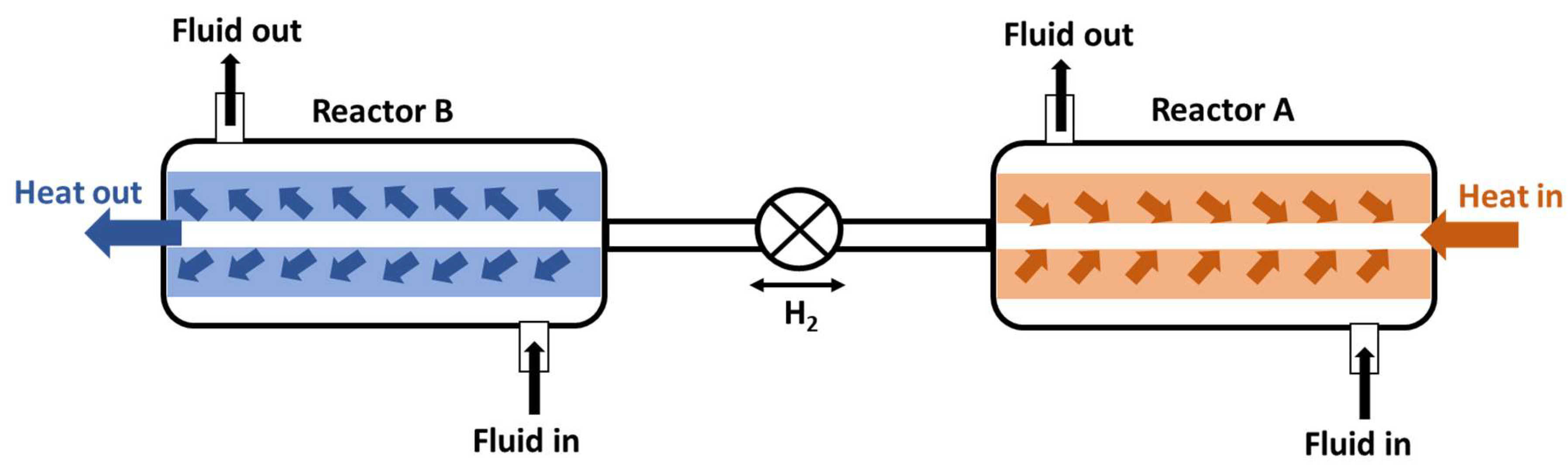
In this system, lanthanum nickel alloy (LaNi5) and magnesium nickel hydride (Mg2Ni) serve as solid materials that facilitate the absorption and release of hydrogen gas. As shown in Figure 12. The cycle initiates in the evaporator, where the refrigerant, in the form of hydrogen gas, absorbs heat from the vehicle's cabin, resulting in a decrease in cabin temperature. As the hydrogen gas absorbs thermal energy, it is transferred to the metal hydride material, which undergoes a chemical reaction that allows it to absorb hydrogen while releasing heat. This process continues until the metal hydride reaches its saturation point with hydrogen. To regenerate the cooling effect, heat is applied to the metal hydride, prompting the release of the absorbed hydrogen gas, which returns to its gaseous state and is directed to the condenser. In the condenser, the contents are cooled, facilitating the transformation of the gas into liquid form and the expulsion of heat to the external environment. Subsequently, the high pressure liquid hydrogen passes through an expansion valve, resulting in a significant reduction in pressure and temperature. The low pressure hydrogen gas then returns to the evaporator, thereby completing the cycle [102], [103]. Recently, this technology has gained attention for its ability to utilize low grade energy sources while maintaining minimal environmental impact [102,104,105].
Linder et al. [106] studied the application of metal hydride systems for AAC, exploring two designs: a closed cooling system for waste heat utilization and an open cooling system for hydrogen powered vehicles. Their results suggested that selecting specific alloys could improve the weight and volume constraints of the metal hydride components, though limitations still existed for the overall system. The specific cooling power of the system restricts its suitability for AAC applications. Qin et al. [107] developed a cooling system and introduced a novel hydride pair for AAC systems that utilizes two metal hydrides, LaNi16Mn2028Al13 and La18Y18Ni3Mn20, owing to their favorable thermodynamic properties and their capacity to efficiently absorb and release hydrogen. Their findings showed a COP of 0.26 and an average cooling power of 84.6 W at temperatures of 150°C, 30°C, and 0°C. Mohan et al. [108] compared experimental and numerical data on metal hydride based air conditioning systems, finding that both sets of data followed similar trends. However, when dynamic properties were considered, the system showed reductions in COP and cooling capacity of 19.1% and 42.4%, respectively.
Kumar et al. [109] explored metal hydride cooling and heating systems for building applications, noting that maximum COP was achieved when both reactors absorbed and desorbed equal amounts of hydrogen. In another study, Linder et al. [110] introduced a system that utilizes the pressure differential of compressed hydrogen gas to produce energy, which could be applied to AAC systems through a sorption based approach using metal hydrides. Here the system uses a hydrogen pressure difference to drive cooling, where metal hydride adsorb hydrogen generating a cooling effect through endothermic reaction and release hydrogen during desorption enabling continuous cooling This system achieved a cooling effect of 900 W and was characterized by simplicity, with a setup weighing only 5 kg. They suggested that energy consumption could be reduced through design optimization, making it more suitable for AAC applications. Gopal et al. [111] analyzed a single stage metal hydride cooling system, the system absorbs heat during the endothermic reaction of metal hydrides with hydrogen, providing cooling. It releases heat during the exothermic desorption phase, influenced by operating temperatures. They conclude that costs could be reduced by optimizing parameters such as thickness, heat transfer coefficient, and effective thermal conductivity. However, the system had a low COP ranging from 0.40 to 0.50. Integration of an internal heat recovery system could improve the COP but at an increased cost.
Metal hydrides are attracting considerable interest for AAC applications due to their ability to utilize waste thermal energy, environmental friendliness, and compactness. Additionally, a wide range of operating temperatures can be achieved by using different alloy combinations, enhancing system efficiency and reducing energy consumption. However, further research is needed to address specific cooling power relative to weight and to optimize bed structure, as these factors pose significant challenges to the implementation of metal hydride systems in air conditioning applications.
4.3 Hybrid Air Conditioning System
Hybrid AC systems combine both active and passive components to minimize energy and fuel consumption. These systems typically draw power from DC batteries or solar photovoltaic (PV) panels, and in some cases, employ thermal energy storage (TES) systems [112], as illustrated in Figure 13. In recent years, EVs have become a promising alternative to conventional vehicles due to their lower energy consumption and reduced emissions. During hot summer months, cabin temperatures can rise significantly, making an effective AC system essential for comfort. However, traditional AC systems in EVs consume large amounts of energy, highlighting the need for alternative, sustainable energy sources. Solar energy, harnessed through solar PV panels, offers a viable solution for energy generation in these systems.
Figure 13.
Illustration of the Hybrid Air conditioning system.
Mei et al. [113] studied the performance and energy consumption of a solar assisted thermoelectric based AAC system. Their results showed that the system, powered by solar energy, provided a cooling effect of 4.01 kW with a COP of 0.433. However, the limited power generated by the PV panels suggested a potential 2% improvement in COP. Pang et al. [114] conducted a feasibility study on an AAC system using solar PV panels, concluding that a minimum cooling capacity of 1500 W is necessary to maintain stable cabin temperatures, with a drop from 26°C to 6°C within one hour. In recent years, the automotive sector has focused on improving the energy efficiency of AC systems, as these improvements can significantly reduce fuel consumption. One strategy to minimize energy use is reducing maximum temperatures and thermal loads. TES systems can effectively lower both cabin temperatures and thermal loads by storing thermal energy during hot conditions and releasing it when the temperatures drop, alleviating the strain on the AAC system.
Jha et al. [115] investigated the use of TES in an AAC system with a fin and tube heat exchanger filled with phase change material (PCM). They compared the air temperature at the vents with and without TES, finding that peak average temperatures were 2.5°C and 2.8°C, respectively. Similarly, Sood et. al. [116] conducted a numerical study on PCM to maintain cabin thermal comfort, demonstrating that PCM integration could reduce temperatures by 6°C. Wang et al. [117] developed an AAC system integrated with TES, designed to store thermal energy while the EV battery is charged from the grid and releases the energy during vehicle operation. Their findings showed that a 0.64 kW PCM heat exchanger could increase the driving range by 20% in winter conditions.
Figure 14.
Illustration of Air conditioning management system.
EVs becoming more popular due to their lower environmental impact. Electric vehicles predominantly utilize batteries as their power source. During the processes of charging and discharging, these batteries generate heat, which can lead to thermal degradation. To mitigate such damage, an effective thermal management system is essential. This system regulates the battery temperature, preventing overheating during alternating current (AC) operation through mechanisms of heat dissipation and active cooling strategies. It continuously monitors and adjusts the cooling processes to ensure optimal performance and safety. A schematic representation of this system is presented by Zhang et. al. in Figure 14. [19]. Jiang et al. [118] developed a model for integrating battery thermal management with the AC system, reporting a temperature differential of 2.5°C between the battery pack and the maximum temperature. They concluded that branching the cooling system from the vehicle’s primary AC system, supported by an expansion valve, could improve battery thermal management performance.
5. Conclusions
This review provides a comprehensive examination of various air conditioning system including active, passive and hybrid design in addition to their application in the automobile sector. As the demand for sustainable solutions grows, particularly with the rise of electric vehicles it is imperative to explore innovative approaches to vehicle air conditioning that minimize energy consumption and reduce environmental impact.
Current AAC systems are significant consumers of energy accounting for approximately 6% of the global energy used by cars. This consumption can escalate to as much as 40% in hot climates and congested traffic [3]. Therefore, the development of alternative AC systems is not only beneficial but essential. Active AC system is very effective however often rely on refrigerants with higher GWP raising concerns about their environmental impact. Conversely, passive AC system demonstrates superior energy efficiency and environmental friendliness making them a compelling choice for future vehicle design [119], [120].
Hybrid AC systems represent a promising frontier combining the benefits of both active and passive technologies. These systems can optimize energy use while providing effective climate control of vehicles. However, the complexity of their integrated design and the need for advanced control systems present challenges that require further research and innovation.
Future research must prioritize the development of eco friendly refrigerants with low GWP to mitigate the negative environmental effects associated with traditional refrigerants. Additionally, enhancing the efficiency of both active and passive systems through improved thermal management and innovative engineering solutions will be crucial. Establishing regulatory frameworks to measure and control energy consumption and emissions from AC systems will also play a vital role in promoting sustainable practices within the automotive industry.
Here, Table 2. summarizes the key characteristics and comparisons of various air conditioning systems and Table 3. Shows the relative evaluation of all the AAC systems described in this review on a 5 point scale across several criteria [121].
Table 2.
Comparison of Alternative Air Conditioning Systems.
| System | Description | Advantages | Challenges | Prospects for R&D |
|---|---|---|---|---|
|
Traditional refrigeration system consists of a compressor, condenser, expansion, valve, and evaporator. Operates by compressing a refrigerant that absorbs and releases heat during phase change. |
High efficiency and effective cooling. Establish technology along with extensive infrastructure. Reliable performance under different conditions. |
High negative impact on the environment from refrigerant and fuel consumption. GHG emissions cause climate change. |
Enhance efficiency through the use of intelligent control systems. Development of Eco-friendly refrigerant. Potential integration with renewable energy sources. |
|
Operates on reverse Brayton cycle using air as a working fluid. Circulate air in a close cycle without phase change to provide cooling. |
Environmentally friendly with zero ODP and GWP Lightweight and compact design. Abundant air as the working fluid. |
Bulky components like compressor and turbine. Limited integration in automobile applications due to reliance on synthetic refrigerants. |
Optimizing component design. Potential for integration into the automobile system. Increasing interest due to environmental regulation. |
|
Operates on the Peltier effect where electric energy creates a temperature difference across thermodynamic modules. No moving parts except a pump. |
Quick cooling response Compact design and easy to intricate. No harmful refrigerant is needed. Able to cool targeted areas. |
Efficiency highly depends on the temperature difference on the cooling module. Limited cooling capacity for larger spaces. |
Research for advanced materials to improve efficiency. Potential for use on EVs. |
|
Powered by thermal energy. Uses an absorber and generator instead of a compressor. Typically utilize ammonia as their refrigerant. |
Lower energy consumption compared to VCR. Lower atmospheric effects from ammonia. |
Large system size and weight. Low COP Ammonia toxicity poses safety concerns. |
Research aimed at optimizing absorbent Efforts to reduce size and weight. |
|
Combined solid absorbent with refrigerant. Use thermal energy for cooling. |
Able to utilize waste heat for operation. Environmentally friendly. |
High weight and space requirements. Complexity in design and implementation. |
Development of efficient design to practical application. Interest in integrating with renewable energy. |
|
Variation of VCR system that uses ejectors to maintain refrigerant flow instead of conventional compressors. | Reduce refrigerant leakage compared to traditional compressors. Simplified design and operation. Utilizes waste heat. |
COP and efficiency are lower compared to VCR. Larger systems may face operational challenges. |
Research for improved efficiency and performance. Potential for application in a hybrid system. Exploring new material for ejectors. |
|
Utilize heat generated from the chemical reaction between hydrogen and metal hydride to produce cooling without compressing the working fluid. | Utilize low-grade waste thermal energy. Environmentally friendly with minimum emission. Compact system design |
Low cooling power relative to weight. Optimization of bed structure is needed. |
Research into improving cooling capacity and efficiency. Potential integration with hydrogen fuel technology. |
|
Combines both active electric and passive thermal storage components. Often powered by batteries or solar energy. |
Reduce energy and fuel consumption. Sustainable approach for electric vehicles. Capable of managing cabin temperature. |
Complexity in energy management and system integration. Reliance on external energy sources. |
Promising for future vehicle design. Specially for EV absorption Research into optimizing energy management systems. Potential for integration with smart grid technologies. |
Table 3.
Comparison of Alternative Automobile Air Conditioning System on a 5 point scale [121].
Table 3.
Comparison of Alternative Automobile Air Conditioning System on a 5 point scale [121].
| Automobile AC System Method |
Development Phase |
COP | Eco-Friendly | Weight & Size | Complexity |
|---|---|---|---|---|---|
| VCR system using control and monitoring management system | 5 | 5 | 2 | 4 | 4 |
| VCR system using dehumidification system | 5 | 5 | 2 | 4 | 4 |
| VCR system using system design optimization | 5 | 5 | 2 | 4.5 | 4 |
| Air cycle refrigeration system | 5 | 1 | 5 | 1 | 3 |
| Thermoelectric system | 4 | 1 | 5 | 3 | 4 |
| Vapor absorption system | 2 | 1 | 5 | 2 | 2 |
| Vapor adsorption system | 2 | 1 | 5 | 2 | 3 |
| Ejector system | 3 | 1 | 5 | 3 | 3 |
| Metal hydride system | 2 | 1 | 5 | 2 | 3 |
| Hybrid system | 4 | 2 | 4 | 2 | 3 |
| Note: | |||||
| |||||
Here, the tables illustrate the trade offs between different AC systems, emphasizing the need for ongoing innovation and research. By understanding these trade offs manufacturers can make informed decisions that align with sustainability goals while meeting consumers' demands for comfort and efficiency.
Automobile industry standards and regulations often favor established air conditioning systems over emerging innovative technologies. Factors such as lower development phase, efficiency, and size/weight compliance pose challenges for the adoption of alternative systems. Eco friendliness, though advantageous for some innovations, may not be sufficiently incentivized by current regulations. The increased complexity of novel approaches also makes it difficult to meet reliability and cost effectiveness requirements. Overcoming these barriers will likely require regulatory updates and closer collaboration between policymakers, researchers, and industry stakeholders [122].
The advancement of air conditioning systems in vehicles plays a vital role in tackling the pressing issues of climate change and energy efficiency. As the automotive industry shifts towards more sustainable practices, it is essential to adopt innovative AC technologies that minimize energy consumption and environmental impact. by exploring and implementing eco friendly refrigerants and optimizing system designs manufacturers can significantly enhance the overall efficiency of vehicle climate control systems. This commitment not only meets consumer demand for comfort but also aligns with global sustainability goals contributing to a cleaner and more energy efficient transportation sector.
Author Contributions
Conceptualization, JKY; methodology, MJ; writing—original draft preparation, SAR.; writing—review and editing, JHJ; visualization, HSS. All authors have read and agreed to the published version of the manuscript.
Funding
This work was supported by the Human Resources Development of the Korea Institute of Energy Technology Evaluation and Planning (KETEP) grant funded by the Ministry of Trade, Industry and Energy of Korea (No. RS 2024 00401705). This work was supported by Korea Institute of Energy Technology Evaluation and Planning (KETEP) grant funded by the Korea government (MOTIE) (RS-2023-00243201 (Global talent Development project for Advanced SMR Core Computational Analysis Technology Development)).This work was supported by the Gachon University research fund of 2022(GCU 202301140001).
Data Availability Statement
Data available on request from the authors.
Conflicts of Interest
The authors declare no conflicts of interest.
Abbreviations
The following abbreviations are used in this manuscript:
| AAC | Automotive air conditioning |
| AC | Air condition |
| ACR | Air cycle refrigeration |
| CCS | Climate Control System |
| PAC | Passive air conditioning |
| PCM | Phase change material |
| PV | Photovoltaic |
| ROC | Representative operation condition |
| COP | Coefficient of performance |
| DC | Direct current |
| EVs | Electric vehicles |
| GHG | Greenhouse gas |
| TEAC | Thermoelectric air conditioning |
| TEGs | Thermoelectric generators |
| TES | Thermal energy storage |
| VARS | Vapor absorption Refrigeration system |
| GWP | Global warming potential |
| HVAC | Heating, ventilation, and air conditioning |
| ODP | Ozone depletion potential |
| VC | Vapor compression |
| VCR | Vapor compression refrigeration |
| VFD | Variable frequency driven |
References
- Shahzad, M.W.; Burhan, M.; Ang, L.; Ng, K.C. Energy water environment nexus underpinning future desalination sustainability. Desalination 2017, 413, 52–64. [Google Scholar] [CrossRef]
- Friedlingstein, P.; et al. Persistent growth of CO2 emissions and implications for reaching climate targets. Nat. Geosci. 2014, 7, 709–715. [Google Scholar] [CrossRef]
- IEA, “Cooling on the Move. Cool. Move, no. September, 2019, [Online]. Available: https://www.iea.org/reports/cooling on the move.
- Bentrcia, M.; Alshatewi, M.; Omar, H. Developments of vapor compression systems for vehicle air conditioning: A review. Adv. Mech. Eng. 2017, 9, 1–15. [Google Scholar] [CrossRef]
- Johnson, V.H. Fuel Used for Vehicle Air Conditioning: A State by State Thermal Comfort Based Approach Fuel Used for Vehicle Air Conditioning: A State by State Thermal Comfort Based Approach. Proc. Futur. Car Congr. 2002, 2022, 724. [Google Scholar]
- Farrington, R.; Rugh, J. Impact of Vehicle Air Conditioning on Fuel Economy, Tailpipe Emissions, and Electric Vehicle Range. Earth Technol. Forum, no. September, p. http://www.nrel.gov/docs/fy00osti/28960.pdf, 2000, [Online]. Available: http://www.smesfair.com/pdf/airconditioning/28960.pdf.
- Pandya, B.; El Kharouf, A.; Venkataraman, V.; Wilckens, R.S. Comparative study of solid oxide fuel cell coupled absorption refrigeration system for green and sustainable refrigerated transportation. Appl. Therm. Eng. 2020, 179, 115597. [Google Scholar] [CrossRef]
- AlQdah, K.; Alsaqoor, S.; Al Jarrah, A. Design and Fabrication of Auto Air Conditioner Generator Utilizing Exhaust Waste Energy from a Diesel Engine. Int. J. Therm. Environ. Eng. 2010, 3, 87–93. [Google Scholar] [CrossRef]
- Jose, S.S.; Chidambaram, R.K. Electric Vehicle Air Conditioning System and Its Optimization for Extended Range—A Review. World Electr. Veh. J. 2022, 13. [Google Scholar] [CrossRef]
- Zhang, Z.; Wang, J.; Feng, X.; Chang, L.; Chen, Y.; Wang, X. The solutions to electric vehicle air conditioning systems: A review. Renew. Sustain. Energy Rev. 2018, 91, 443–463. [Google Scholar] [CrossRef]
- Suzuki, T.; Ishii, K. Air conditioning system for electric vehicle. SAE Tech. Pap. 1996, 7, 407–413. [Google Scholar] [CrossRef]
- Pan, L.; Liu, C.; Zhang, Z.; Wang, T.; Shi, J.; Chen, J. Energy saving effect of utilizing recirculated air in electric vehicle air conditioning system. Int. J. Refrig. 2019, 102, 122–129. [Google Scholar] [CrossRef]
- Al Faruque, M.A.; Vatanparvar, K. Modeling, analysis, and optimization of Electric Vehicle HVAC systems. Proc. Asia South Pacific Des. Autom. Conf. ASP DAC 2016, 25, 423–428. [Google Scholar] [CrossRef]
- Aceves, S.M. An analytical comparison of adsorption and vapor compression air conditioners for electric vehicle applications. J. Energy Resour. Technol. Trans. ASME 1996, 118, 16–21. [Google Scholar] [CrossRef]
- Jawale, S.; Deokar, S.; Avhad, H.; Mulani, S.; Sir, P.B. Review on Laws of Thermodynamics. www.irjmets.com @International Res. J. Mod. Eng. 2023, 5, 2281–2285. [Google Scholar]
- Marletta, L. Air conditioning systems from a 2nd law perspective. Entropy 2010, 12, 859–877. [Google Scholar] [CrossRef]
- Aftermarket, M. Automotive air conditioning What is thermal management ?. Automot. air Cond. A Compact Guid. Work., p. 84, 2021, [Online]. Available: https://www.mahle aftermarket.com/media/homepage/facelift/media center/klima/kompaktwissen ac fahrzeugklimatisierung en screen.pdf.
- Weilenmann, M.F.; Vasic, A.M.; Stettler, P.; Novak, P. Influence of mobile air conditioning on vehicle emissions and fuel consumption: A model approach for modern gasoline cars used in Europe. Environ. Sci. Technol. 2005, 39, 9601–9610. [Google Scholar] [CrossRef] [PubMed]
- Zhang, Z.; Wang, J.; Feng, X.; Chang, L.; Chen, Y.; Wang, X. The solutions to electric vehicle air conditioning systems: A review. Renew. Sustain. Energy Rev. 2018, 91, 443–463. [Google Scholar] [CrossRef]
- Alani, W.K.; Zheng, J.; Fayad, M.A.; Lei, L. Erratum: Enhancing the fuel saving and emissions reduction of light duty vehicle by a new design of air conditioning worked by solar energy (Case Studies in Thermal Engineering (2022) 30, (S2214157X22000442), (10. 1016/j.csite.2022.101798)). Case Stud. Therm. Eng. 2023, 51, 103599. [Google Scholar] [CrossRef]
- Eichhorn, R.H.L.; Boot, M.D.; Luijten, C.C.M. Waste energy driven air conditioning system (wedacs). SAE Int. J. Engines 2010, 2, 477–492. [Google Scholar] [CrossRef]
- Weckerle, C.; Nasir, M.; Hegner, R.; Bürger, I.; Linder, M. A metal hydride air conditioning system for fuel cell vehicles – Functional demonstration. Appl. Energy 2020, 259, 114187. [Google Scholar] [CrossRef]
- Foster, S.; Elzinga, D. The role of fossil fuels in a sustainable energy system. UN Chron. 2013, 52, 17–19. [Google Scholar] [CrossRef]
- Bach, W. Fossil fuel resources and their impacts on environment and climate. Int. J. Hydrogen Energy 1981, 6, 185–201. [Google Scholar] [CrossRef]
- How, P.M.; Air, D.; Work, C.; Cars, E.; Concept, N. How Does Air Conditioning Work in Electric Cars ? Why Having an Air Conditioning. pp. 1–18.
- Makino, M.; Ogawa, N.; Abe, Y.; Fujiwara, Y. Automotive air conditioning electrically driven compressor. SAE Tech. Pap., 2003.
- Hannan, M.A.; Hoque, M.M.; Mohamed, A.; Ayob, A. Review of energy storage systems for electric vehicle applications: Issues and challenges. Renew. Sustain. Energy Rev. 2017, 69, 771–789. [Google Scholar] [CrossRef]
- Daut, I.; Adzrie, M.; Irwanto, M.; Ibrahim, P.; Fitra, M. Solar powered air conditioning system. Energy Procedia 36, no. September 2013, 2015, 444–453. [Google Scholar] [CrossRef]
- Quick, B.D. Solar powered air conditioning for vehicles developed. pp. 1–9, 2010. [Online]. Available: https://newatlas.com/solar power vehicle ac system/16979/.
- Lethwala, Y.; Garg, P. ‘Development of Auxiliary Automobile Air Conditioning System by Solar Energy,’” Int. Res. J. Eng. Technol. 2017, 4, 737–742, [Online]. Available: https://irjet.net/archives/V4/i7/IRJET V4I7186.pdf. [Google Scholar]
- Petróci, J.; Mantič, M.; Sloboda, O. Power loss in a combustion engine of a prototype vehicle. Diagnostyka 2017, 18, 59–64. [Google Scholar]
- Asfahan, H.M.; Sultan, M.; Universitesi, I.M. Study on engine waste heat recovery for automobile air conditioning. no. December, 2020.
- De Boer, R. Thermally Operated Mobile Air Conditioning Systems. no. January, 2015.
- Wu, S.; Feng, L.; Changizian, S.; Raeesi, M.; Aiedi, H. Analysis of air conditioning system impact on a fuel cell vehicle performance based on a realistic model under actual urban conditions. Int. J. Hydrogen Energy 2022, 47, 25899–25912. [Google Scholar] [CrossRef]
- Mahmood, R.A.; Ali, O.M.; Al Janabi, A.; Al Doori, G.; Noor, M.M. Review of Mechanical Vapour Compression Refrigeration System Part 2: Performance Challenge. Int. J. Appl. Mech. Eng. 2021, 26, 119–130. [Google Scholar] [CrossRef]
- Alahmer, A.; Omar, M.A.; Mayyas, A.; Dongri, S. Effect of relative humidity and temperature control on in cabin thermal comfort state: Thermodynamic and psychometric analyses. Appl. Therm. Eng. 2011, 31, 2636–2644. [Google Scholar] [CrossRef]
- Alahmer, A.; Omar, M.; Mayyas, A.R.; Qattawi, A. Analysis of vehicular cabins’ thermal sensation and comfort state, under relative humidity and temperature control, using Berkeley and Fanger models. Build. Environ. 2012, 48, 146–163. [Google Scholar] [CrossRef]
- Alahmer, A. Thermal analysis of a direct evaporative cooling system enhancement with desiccant dehumidification for vehicular air conditioning. Appl. Therm. Eng. 2016, 98, 1273–1285. [Google Scholar] [CrossRef]
- Nagaya, K.; Senbongi, T.; Li, Y.; Zheng, J.; Murakami, I. High energy efficiency desiccant assisted automobile air conditioner and its temperature and humidity control system. Appl. Therm. Eng. 2006, 26, 1545–1551. [Google Scholar] [CrossRef]
- Amri, H.; Hofstädter, R.N.; Kozek, M. Energy efficient design and simulation of a demand controlled heating and ventilation unit in a metro vehicle. 2011 IEEE Forum Integr. Sustain. Transp. Syst. FISTS 2011, 2011, 7–12. [Google Scholar] [CrossRef]
- Luger, C.; Kallinovsky, J.; Rieberer, R. Identification of representative operating conditions of HVAC systems in passenger rail vehicles based on sampling virtual train trips. Adv. Eng. Informatics 2016, 30, 157–167. [Google Scholar] [CrossRef]
- Yin, X.; Wang, X.; Li, S.; Cai, W. Energy efficiency oriented cascade control for vapor compression refrigeration cycle systems. Energy 2016, 116, 1006–1019. [Google Scholar] [CrossRef]
- Yin, X.; Li, S.; Li, N.; Zheng, Y.; Cai, W. Energy saving oriented control strategy for vapor compression refrigeration cycle systems. Proc. 2014 9th IEEE Conf. Ind. Electron. Appl. ICIEA 2014, 2014, 1561–1566. [Google Scholar] [CrossRef]
- Subiantoro, A.; Ooi, K.T.; Stimming, U. Energy Saving Measures for Automotive Air Conditioning ( AC ) System in the Tropics. 15th Int. Refrig. Air Cond. Conf., 1–8, 2014, [Online]. Available: http://docs.lib.purdue.edu/iracc.
- Weng, C.L.; Kau, L.J. Design and implementation of a low energy consumption air conditioning control system for smart vehicle. J. Healthc. Eng. 2019, 2019. [Google Scholar] [CrossRef]
- Subramanyam, N.; Maiya, M.P.; Murthy, S.S. Application of desiccant wheel to control humidity in air conditioning systems. Appl. Therm. Eng. 2004, 24, 2777–2788. [Google Scholar] [CrossRef]
- Subramanyam, N.; Maiya, M.P.; Murthy, S.S. Parametric studies on a desiccant assisted air conditioner. Appl. Therm. Eng. 2004, 24, 2679–2688. [Google Scholar] [CrossRef]
- Ibrahim, M.M.M. A comparative experimental study on the performance of the air conditioning system through effective condenser cooling and preheating the refrigerant. Environ. Prog. Sustain. Energy 2021, 40. [Google Scholar] [CrossRef]
- Chang, T.B.; Sheu, J.J.; Huang, J.W. High efficiency hvac system with defog/dehumidification function for electric vehicles. Energies 2021, 14, 1–12. [Google Scholar] [CrossRef]
- Tang, C.; Vafai, K.; Gu, C.; Gloria, K.N.; Karim, M.D.R. Experimental investigation of dehumidification performance of a vapor compression refrigeration system. Int. Commun. Heat Mass Transf. 2022, 137, 106282. [Google Scholar] [CrossRef]
- Yu, J.; Su, L.; Li, K.; Liu, M.; Zhang, H. Investigation on heat transfer characteristics of outside heat exchanger in an air conditioning heat pump system for electric vehicles. Int. J. Heat Mass Transf. 2021, 170, 121040. [Google Scholar] [CrossRef]
- Kapoor, S.H.; Arora, G.; Sangeet, M.; Kapoor, H.; Sachin, M. International Refrigeration and Air Conditioning Conference School of Mechanical Engineering. 2004, [Online]. Available: http://docs.lib.purdue.edu/iracc/736.
- “ENGINEERING UNIT I Air Refrigeration Cycles”, [Online]. Available: https://www.vssut.ac.in/lecture_notes/lecture1424265736.pdf.
- Shengjun, L.; Zhenying, Z.; Lili, T. Thermodynamic analysis of the actual air cycle refrigeration system. Syst. Eng. Procedia 2011, 1, 112–116. [Google Scholar] [CrossRef]
- Zhang, Z.; Liu, S.; Tian, L. Thermodynamic analysis of air cycle refrigeration system for Chinese train air conditioning. Syst. Eng. Procedia 2011, 1, 16–22. [Google Scholar] [CrossRef]
- Yang, X.; Wang, Z.; Zhang, Z.; Chen, S.; Hou, Y.; Chen, L. Thermodynamic Analysis of Air Cycle Refrigeration Systems with Expansion Work Recovery for Compartment Air Conditioning. Appl. Sci. 2022, 12. [Google Scholar] [CrossRef]
- Spence, S.W.T.; Doran, W.J.; Artt, D.W. Design, construction and testing of an air cycle refrigeration system for road transport. Int. J. Refrig. 2004, 27, 503–510. [Google Scholar] [CrossRef]
- Spence, S.W.T.; Doran, W.J.; Artt, D.W.; McCullough, G. Performance analysis of a feasible air cycle refrigeration system for road transport. Int. J. Refrig. 2005, 28, 381–388. [Google Scholar] [CrossRef]
- Caron, J.; Markusen, J.R. Development of an Air Cycle Environmental Control System for Automotive Applications. no. December, 1–23, 2016, [Online]. Available: https://digitalcommons.calpoly.edu/cgi/viewcontent.cgi?article=1208&context=theses.
- Mahajan, V.N.; Nagdeve, S.R. Design of Air Conditioning System by Using Air Refrigeration Cycle for Cooling the Cabinet of Truck. J. Mech. Civ. Eng. 2016, 13, 19–23. [Google Scholar]
- Enescu, D. Thermoelectric Refrigeration Principles. Bringing Thermoelectr. into Real., 2018. [CrossRef]
- Raut, M.S.; Heat, M.T.; Engg, P. Thermoelectric Air Cooling For Cars. Int. J. Eng. Sci. Technol. 2012, 4, 2381–2395. [Google Scholar]
- Maranville, C.W.; et al. Modeling, Zonal Design, and Thermoelectric Devices. DEER Conf., 2012.
- Stancila, M.; Ene, C.A.; Ivanescu, M.; Tabacu, I.; Neacsu, A.C. Studies on the Use of Thermoelectric Elements for Improving Thermal Confort in Automobile 2013, 24, 13–20,.
- Yogesh, N. Air Conditioning System in Car using Thermoelectric Effect. Int. J. Eng. Res. 2020, 9, 374–377. [Google Scholar] [CrossRef]
- Thalkar, A.; Vaidya, P.; Nikam, S.; Patil, S.; Shendre, L. Study of Thermoelectric Air Conditioning for Automobiles. Int. Res. J. Eng. Technol. 2018, 1084–1087, [Online]. Available: www.irjet.net.
- Attar, A.; Lee, H.S.; Weera, S. Experimental Validation of the Optimum Design of an Automotive Air to Air Thermoelectric Air Conditioner (TEAC). J. Electron. Mater. 44, no. 2015, 6, 2177–2185. [Google Scholar] [CrossRef]
- Attar, A.; Lee, H.; Weera, S. Optimal design of automotive thermoelectric air conditioner (TEAC). J. Electron. Mater. 2014, 43, 2179–2187. [Google Scholar] [CrossRef]
- Attar, A.; Lee, H.S. Designing and testing the optimum design of automotive air to air thermoelectric air conditioner (TEAC) system. Energy Convers. Manag. 2016, 112, 328–336. [Google Scholar] [CrossRef]
- Chen, C.; Mao, L.; Lin, T.; Tu, T.; Zhu, L.; Wang, C. Performance testing and optimization of a thermoelectric elevator car air conditioner. Case Stud. Therm. Eng. 2020, 19, 100616. [Google Scholar] [CrossRef]
- Ran, Y.; Deng, Y.; Hu, T.; Su, C.; Liu, X. Energy efficient thermoelectric generator powered localized air conditioning system applied in a heavy duty vehicle. J. Energy Resour. Technol. Trans. ASME 2018, 140. [Google Scholar] [CrossRef]
- Amerigon, A. Amerigon ’ s Climate Control Seat ( TM ) ( CCS ( TM )) System Offered as an Option on 2006 Cadillac DTS Heated / Cooled Seats Among Luxury Features in New High Performance Sedan JB MS. 2006.
- Seddiek, I.S.; Mosleh, M.; Banawan, A.A. Thermo economic approach for absorption air condition onboard high speed crafts. Int. J. Nav. Archit. Ocean Eng. 2012, 4, 460–476. [Google Scholar] [CrossRef]
- Ammar, N.R.; Seddiek, I.S. Thermodynamic, environmental and economic analysis of absorption air conditioning unit for emissions reduction onboard passenger ships. Transp. Res. Part D Transp. Environ. 2018, 62, 726–738. [Google Scholar] [CrossRef]
- Srivastava. S. S. Review Paper on Analysis of Vapour Absorption Refrigeration System. Int. J. Res. Eng. Technol. 2015, 4, 410–413. [CrossRef]
- Tassou, S.A.; De Lille, G.; Ge, Y.T. Food transport refrigeration Approaches to reduce energy consumption and environmental impacts of road transport. Appl. Therm. Eng. 2009, 29, 1467–1477. [Google Scholar] [CrossRef]
- Venkataraman, V.; El Kharouf, A.; Pandya, B.; Amakiri, E.; Wilckens, R.S. Coupling of engine exhaust and fuel cell exhaust with vapour absorption refrigeration/air conditioning systems for transport applications: A review. Therm. Sci. Eng. Prog. 2020, 18, 100550. [Google Scholar] [CrossRef]
- Pandya, B.; El Kharouf, A.; Venkataraman, V.; Wilckens, R.S. Comparative study of solid oxide fuel cell coupled absorption refrigeration system for green and sustainable refrigerated transportation. Appl. Therm. Eng. 2020, 179, 115597. [Google Scholar] [CrossRef]
- Wang, S. Motor vehicle air conditioning utilising the exhaust gas energy to power an absorption refrigeration cycle. Univ. Cape T., p. 144, 1997, [Online]. Available: Natural Refrigerants based Automobile Air Conditioning System.
- Thakre. S. D. T. Cooling of a Truck Cabin By Vapour Absorption Refrigeration System Using Engine Exhaust. Int. J. Res. Eng. Technol. 2014, 3, 816–822. [CrossRef]
- Alam, S. A Proposed model for utilizing exhaust heat to run automobile air conditioner. Proceeding Int. Conf. Sustain. Energy Environ. Bangkok, Thail. 2017, 11, 21–24. [Google Scholar]
- Bulterer, B.; Bulton, R. Alternative technologies for automobile air conditioning. vol. 6 1801, no. ACRCCR Ol, 1991. [Google Scholar]
- Wang, D.C.; Li, Y.H.; Li, D.; Xia, Y.Z.; Zhang, J.P. A review on adsorption refrigeration technology and adsorption deterioration in physical adsorption systems. Renew. Sustain. Energy Rev. 2010, 14, 344–353. [Google Scholar] [CrossRef]
- Fernandes, M.S.; Brites, G.J.V.N.; Costa, J.J.; Gaspar, A.R.; Costa, V.A.F. Review and future trends of solar adsorption refrigeration systems. Renew. Sustain. Energy Rev. 2014, 39, 102–123. [Google Scholar] [CrossRef]
- Elsheniti, M.B.; Elsamni, O.A.; Al dadah, R.K.; Mahmoud, S.; Elsayed, E.; Saleh, K. Adsorption Refrigeration Technologies. Sustain. Air Cond. Syst., no. 19, 2018. 20 October. [CrossRef]
- Lim, L.S.; Abdullah, M.O. Experimental study of an automobile exhaust heat driven adsorption air conditioning laboratory prototype by using palm activated carbon methanol. HVAC R Res. 2010, 16, 221–231. [Google Scholar] [CrossRef]
- Jiangzhou, S.; Wang, R.Z.; Lu, Y.Z.; Xu, Y.X.; Wu, J.Y.; Li, Z.H. Locomotive driver cabin adsorption air conditioner. Renew. Energy 2003, 28, 1659–1670. [Google Scholar] [CrossRef]
- Jiang, Z.; Wang, R.; Lu, Y.; Xu, Y.; Wu, J. Experiments and characteristic analysis on adsorption air conditioner used in internal combustion locomotive driver cabin. Taiyangneng Xuebao/Acta Energiae Solaris Sin. 2003, 24, 32–36. [Google Scholar]
- Abdullah, M.O.; Leo, S.L. Feasibility study of solar adsorption technologies for automobile air conditioning. Int. Sol. Energy Conf. 2005, 283–290. [Google Scholar]
- Abdullah, M.O.; Tan, I.A.W.; Lim, L.S. Automobile adsorption air conditioning system using oil palm biomass based activated carbon: A review. Renew. Sustain. Energy Rev. 2011, 15, 2061–2072. [Google Scholar] [CrossRef]
- Jiang, L.; Wang, R.Z.; Li, J.B.; Wang, L.W.; Roskilly, A.P. Performance analysis on a novel sorption air conditioner for electric vehicles. Energy Convers. Manag. 156, no. November 2018, 2017, 515–524. [Google Scholar] [CrossRef]
- Lu, Y.Z.; Wang, R.Z.; Jianzhou, S.; Zhang, M.; Xu, Y.X.; Wu, J.Y. Performance of a diesel locomotive waste heat powered adsorption air conditioning system. Adsorption 2004, 10, 57–68. [Google Scholar] [CrossRef]
- Besagni, G.; Mereu, R.; Inzoli, F. Ejector refrigeration: A comprehensive review. Renew. Sustain. Energy Rev. 2016, 53, 373–407. [Google Scholar] [CrossRef]
- Nguyen, V.M.; Riffat, S.B.; Doherty, P.S. Development of a solar powered passive ejector cooling system. Appl. Therm. Eng. 2001, 21, 157–168. [Google Scholar] [CrossRef]
- Abdulateef, J.M.; Sopian, K.; Alghoul, M.A.; Sulaiman, M.Y. Review on solar driven ejector refrigeration technologies. Renew. Sustain. Energy Rev. 2009, 13, 1338–1349. [Google Scholar] [CrossRef]
- Chen, L.X.; Hu, P.; Sheng, C.C.; Zhang, N.; Xie, M.N.; Wang, F.X. Thermodynamic analysis of three ejector based organic flash cycles for low grade waste heat recovery. Energy Convers. Manag. 185, no. September 2019, 2018, 384–395. [Google Scholar] [CrossRef]
- Policy, C.; Cookies, A.A. DENSO Develops World ’ s First Passenger Vehicle Air Conditioning System Using an Ejector. pp. 1–6, 2009. [Online]. Available: https://www.denso.com/global/en/news/newsroom/2009/090519 01/.
- Rahamathullah, M.R.; Palani, K.; Venkatakrishnan, P. A Review On Historical And Present Developments In Ejector Systems. Int. J. Eng. Res. Appl. 2013, 3, 10–34. [Google Scholar]
- Mallaki, M.; Dashti, R. Fault locating in transmission networks using transient voltage data. Energy Procedia 2012, 14, 173–180. [Google Scholar] [CrossRef]
- Aligolzadeh, F.; Fard, A.H. A novel methodology for designing a multi ejector refrigeration system. Appl. Therm. Eng. 151, no. November 2019, 2018, 26–37. [Google Scholar] [CrossRef]
- Javani, N.; Dincer, I.; Naterer, G.F. Thermodynamic analysis of waste heat recovery for cooling systems in hybrid and electric vehicles. Energy 2012, 46, 109–116. [Google Scholar] [CrossRef]
- Menon, R.K. Metal Hydride Based Cooling Systems. Int. J. Mech. Eng. Technol. 6, no. 2015, 12, 73–80. [Google Scholar]
- Menon, R.K. Article ID: IJMET_06_12_008 Cite this Article: Rahul K. Menon. Metal Hydride Based Cooling Systems. Int. J. Mech. Eng. Technol. 2015, 6, 73–80, [Online]. Available: http://iaeme.com/Home/journal/IJMET81editor@iaeme.comhttp://iaeme.com/Home/issue/IJMET?Volume=6&Issue=12http://iaeme.com. [Google Scholar]
- Weckerle, C.; Nasri, M.; Hegner, R.; Linder, M.; Bürger, I. A metal hydride air conditioning system for fuel cell vehicles – Performance investigations. Appl. Energy 2019, 256, 113957. [Google Scholar] [CrossRef]
- Weckerle, C.; Nasir, M.; Hegner, R.; Bürger, I.; Linder, M. A metal hydride air conditioning system for fuel cell vehicles – Functional demonstration. Appl. Energy 2020, 259, 114187. [Google Scholar] [CrossRef]
- Linder, M. Automotive cooling systems based on metal hydrides. 2010, [Online]. Available: http://elib.uni stuttgart.de/opus/volltexte/2010/5554/.
- Qin, F.; Chen, J.P.; Zhang, W.F.; Chen, Z.J. Metal hydride work pair development and its application on automobile air conditioning systems. J. Zhejiang Univ. Sci. A 2007, 8, 197–204. [Google Scholar] [CrossRef]
- Mohan, M.; Sharma, M.; Sharma, V.K.; Kumar, E.A.; Satheesh, A.; Muthukumar, P. Performance analysis of metal hydride based simultaneous cooling and heat transformation system. Int. J. Hydrogen Energy 2019, 44, 10906–10915. [Google Scholar] [CrossRef]
- Kumar, S.; et al. Studies on a metal hydride based year round comfort heating and cooling system for extreme climates. Energy Build. 244, 2021. [CrossRef]
- Linder, M.; Kulenovic, R. An energy efficient air conditioning system for hydrogen driven cars. Int. J. Hydrogen Energy 2011, 36, 3215–3221. [Google Scholar] [CrossRef]
- Gopal, M.R.; Murthy, S.S. Performance of a metal hydride cooling system. Int. J. Refrig. 1995, 18, 413–420. [Google Scholar] [CrossRef]
- Bindu, R.S.; Shalgar, S.; Salunke, A.; Salunkhe, A. Design, development & performance evaluation of sustainable, hybrid air conditioning system for automobiles. Int. J. Syst. Innov. 2024, 8, 84–98. [Google Scholar] [CrossRef]
- Mei, V.C.; Chen, F.C.; Mathiprakasam, B.; Heenan, P. Study of solar assisted thermoelectric technology for automobile air conditioning. J. Sol. Energy Eng. Trans. ASME 1993, 115, 200–205. [Google Scholar] [CrossRef]
- Pang, W.; Yu, H.; Zhang, Y.; Yan, H. Solar photovoltaic based air cooling system for vehicles. Renew. Energy 2019, 130, 25–31. [Google Scholar] [CrossRef]
- Jha, K.K.; Badathala, R. Low Temperature Thermal Energy Storage (TES) System for Improving Automotive HVAC Effectiveness. SAE Tech. Pap. 2015, 2015. [Google Scholar]
- Sood, D.; Das, D.; Ali, S.F.; Rakshit, D. Numerical analysis of an automobile cabin thermal management using passive phase change material. Therm. Sci. Eng. Prog. 2021, 25, 100870. [Google Scholar] [CrossRef]
- Wang, M.; Wolfe, E.; Craig, T.; Abdelaziz, O.; Gao, Z. Design and Testing of a Thermal Storage System for Electric Vehicle Cabin Heating. SAE Tech. Pap., 1–7, 2016.
- Cen, J.; Jiang, F. Li ion power battery temperature control by a battery thermal management and vehicle cabin air conditioning integrated system. Energy Sustain. Dev. 2020, 57, 141–148. [Google Scholar] [CrossRef]
- Yunus, H.M.; Nasution, H.; Aziz, A.A.; Sumeru, K.; Dahlan, A.A. The Effect of Ambient Temperature on the Performance of Automotive Air Conditioning System. Appl. Mech. Mater. 2016, 819, 221–225. [Google Scholar] [CrossRef]
- Khayyam, H.; Kouzani, A.Z.; Hu, E.J. Reducing energy consumption of vehicle air conditioning system by an energy management system. IEEE Intell. Veh. Symp. Proc. 2009; 752–757. [Google Scholar] [CrossRef]
- Bentrcia, M.; Alshitawi, M.; Omar, H. Developmens of alternative systems for automotive air conditioning A review. J. Mech. Sci. Technol. 2018, 32, 1857–1867. [Google Scholar] [CrossRef]
- Calm, J.M. The next generation of refrigerants Historical review, considerations, and outlook. Int. J. Refrig. 2008, 31, 1123–1133. [Google Scholar] [CrossRef]
Disclaimer/Publisher’s Note: The statements, opinions and data contained in all publications are solely those of the individual author(s) and contributor(s) and not of MDPI and/or the editor(s). MDPI and/or the editor(s) disclaim responsibility for any injury to people or property resulting from any ideas, methods, instructions or products referred to in the content. |
© 2025 by the authors. Licensee MDPI, Basel, Switzerland. This article is an open access article distributed under the terms and conditions of the Creative Commons Attribution (CC BY) license (https://creativecommons.org/licenses/by/4.0/).
Copyright: This open access article is published under a Creative Commons CC BY 4.0 license, which permit the free download, distribution, and reuse, provided that the author and preprint are cited in any reuse.


