
Submitted:
10 February 2025
Posted:
10 February 2025
You are already at the latest version
Abstract
This article presents a rock armour stability formula for coastal revetments under depth-limited breaking waves that defines requisite armour mass as a function of incident wave energy. Parameters include wave height, wave period, toe depth, revetment slope, specific gravity of armour and water, percentage damage and the number of waves. The formula has been calibrated empirically based on unpublished project, unpublished research and published research flume test data. It departs from existing approaches by using wave energy in lieu of wave height as the disturbing parameter, but adopts other parameters developed by previous researchers. Results are compared with established formulae and display better coherence with the flume data.
Keywords:
coastal revetment
; rock armour
; stability
; depth-limited breaking wave energy
; physical model
1. Introduction
1.1. Background
Typically, coastal revetments are constructed to prevent wave erosion of dunes and foreshores. Revetments may be subjected to waves that shoal and dissipate on the revetment slope, the revetment toe being in relatively deep water, to waves that shoal on the seabed immediately in front of the revetment, breaking directly onto it, and to waves that have shoaled and broken on the seabed prior to reaching the revetment. The latter conditions have revetment toes in relatively shallow water, being the subject of this research.
The revetment armour is underlain by a separating filter layer overlying fine-grained sediment. While allowing for groundwater seepage, these underlying materials are impermeable to incident wave energy, which is reflected onto the revetment armour. Therefore, the stability of revetment armour is somewhat compromised compared with breakwater armouring that, commonly, overlies a permeable core.
Armour units for revetments subjected to wave impact are designed with formulae developed and calibrated empirically using hydraulic scale models [1,2,3]. Early work defined the median requisite armour mass, M50, as a function of wave height, rock density, water density and revetment slope following the passage of some 1,000 regular waves, being the Hudson formula [1]. These tests were undertaken on sloping structures for permeable breakwaters under regular non-breaking waves. Empirical coefficients for a range of various concrete armour units and rock types for both non-breaking and breaking waves have been developed subsequently. The Hudson formula is:
where M50 is the median armour mass (kg), ρa is the armour density (kg/m3), Hs is the incident significant wave height (m), Δ is the relative density of the armour to water ((ρa - ρw)/ρw), KD is a damage coefficient derived empirically and cotα is the revetment armour slope.
Testing of rock armour and various concrete armour units under breaking waves was undertaken in a wave flume at the University of New South Wales Water Research Laboratory (UNSW WRL) [4,5]. The testing under regular waves found that KD depended on percentage damage D thus ([4,5] p28):
where (a, n) = (1.2, 0.51) for two layers of random rock on an impermeable core and D is percentage damage (0 < D < 0.20). This form of expression for the Hudson damage coefficient has been adopted for subsequent modifications to the Hudson formula by others [2,6].
Later research included formulae calibrated empirically for both surging and plunging random waves on sloping revetments and breakwaters. The van der Meer formulae [2] encompassed a larger range of relevant parameters including the Iribarren number (wave period), core permeability, degree of damage and the number of zero-crossing waves. Most of the tests comprised relatively deep water at the structure toe. The requisite armour mass was formulated as a function of wave height cubed for plunging conditions:
and for surging conditions:
where P is a permeability parameter of the armour underlayers, εm is the Iribarren number using the mean wave period, , AE is the cross-sectional eroded area, Dn50 is the nominal median diameter of the armour stones, N is the number of zero-crossing waves with calibration coefficients Cpl = 6.2 and Cs = 1.0. As , and Dn50 is likely to be included in the derivation of P, although not given in the reference [2], Dn50 is included both in the dependent and independent variables.
The most recent development of these formulae, being that of van Gent [6], included testing of two sloping structures with impermeable underlayers. The van Gent formula can be expressed as:
with Dn50 included in both the dependent and independent variables.
With this development, the influence of wave period was considered small compared with the amount of scatter in the data due to other reasons [6]. Therefore, the wave period was not used in this formula and there was no separation between “plunging” conditions and “surging” conditions [6].
These formulae, (3) and (4), have been revised recently with changes made to the calibration coefficients and to the wave period parameters to be used [7,8]. However, their basic structures have remained the same.
Typical conditions studied by van der Meer [2] had revetment toes in relatively deep water, with waves dissipating on the revetment slope, whereas van Gent [3] and Gordon [4,5] considered waves breaking onto the revetment armour directly from the fronting seabed.
More recently, numerical models such as SPH (Smoothed Particle Hydrodynamics), IHFOAM, waves2Foam, and DualSPHysics have been developed for overtopping and armour stability research [9,10,11]. These models can be expensive computationally, particularly when applied to solve large domains and long duration wave trains, which may be required for wave-structure interaction ([11] p80). However, significant progress has been made on wave interaction with porous structures with these models that do not require complex meshes nor any special treatment for the free-surface flows ([11] p80).
As many numerical models rely on physical modelling for validation, the role of physical hydraulic scale modelling of coastal protection structures remains relevant [12]. The empirical approaches based on physical model studies defined the median requisite armour mass as a function of, inter alia, incident wave height cubed [1,2,3]. No explanation for this has been proffered other than it would appear to have been necessary to ensure dimensional integrity of the formulae. However, other researchers have proposed sediment transport as a function of incident wave energy ([13] p27).
1.2. Thesis
It is the energy of breaking waves that applies the disturbing forces to revetment armour and it is the mass of that armour that secures or otherwise its stability. This article examines revetment rock armour stability as a function of incident wave energy, E, which is a function of the product of wave height squared and wavelength ([14] p2-26, eqn(2-38)) thus:
where g is gravitational acceleration, L is the nearshore wavelength. In shallow water, the nearshore wavelength can be approximated by ([14] p2-25 eqn2-37, [15]):
where htoe is the nearshore depth at the revetment.
The following wave energy formula is proposed for the requisite rock armour mass on an impermeable core revetment, adopting the dependence on armour slope from van der Meer [2] and incorporating nearshore depth and wave period through wavelength:
2. Method
2.1. Data
Data for this research comprised:
2.2. Physical Modelling
2.2.1. Manly Hydraulics Laboratory
Two-dimensional physical model testing for the rock armoured revetments of the Mardie embankments was undertaken in 1 m and 3 m wide flumes (Figure 3). Model armour comprised two layers of a well graded igneous rock of specific gravity s.g. = 2.76. The rock was placed with a porosity of 40% on an impermeable slope of cotα = 2.5. Testing was undertaken with random waves in fresh water.
For the 1 m wide flume model, the seabed slope was flat (m = 0) and M50 = 0.056 kg (Figure 4(a)). Most of the tests comprised some 3,000 waves of peak period Tp = 1.2 s, although some tests were undertaken with fewer waves (100, 300, 500). For the 3 m wide flume model, the seabed slope was m = 0.006 and M50 = 0.034 kg (Figure 4(c)). Tests comprised some 2,000 zero-crossing waves with peak period Tp = 2.5 s.
The modelling comprised testing the armour rock stability over a range of water levels with depth-limited breaking waves, recording the subsequent damage. Damage was observed by comparing photographs taken before and after exposure to the test conditions. Damage was quantified by counting the number of units displaced by more than one nominal diameter as a percentage of the total number of units within the wave runup/rundown section of the revetment. All rocks in the two armour layers were considered exposed. Only results with damage less than 15% for severe breaking were considered, defined as Hs/htoe > 0.4 for these very flat slopes on which the maximum wave height that can be sustained is around 55% of the depth [20,21]. Test and reduced data are in Table 1.
2.2.2. Delft Hydraulics
Data were reviewed from tests undertaken in the 1 m wide flume of Delft Hydraulics in 1983-1986 [2] and in 2003 [3,6]. The former are documented comprehensively in the thesis of professor van der Meer, which is publicly and readily available. Included were some 132 tests with rough angular armourstone of Dn50 = 0.036 m on impermeable underlayers of slopes cotα= 2, 3, 4, and 6, Tm varying from 1.3 s to 3.3 s, damage recorded after 1,000 and 3,000 waves with damage after 3,000 waves varying from S = 0.6 to 33.0. As Hs/htoe varied from 0.06 to 0.32 with an average value of 0.16, the revetment toe was in relatively deep water with waves collapsing and dissipating on the revetment slope, rather than shoaling and breaking onto it from the fronting seabed. These data were not considered in this analysis.
For the tests in 2003, the armour comprised well sorted “standard rough angular rock” of specific gravity 2.75 with Dn50 = 0.026 m [6]. The revetments were on impermeable cores at slopes of cotα = 2 (for Structure No. 6) and cotα = 4 (for Structure No. 7). The seabed slope was m = 0.033. Only considered were results with damage S < 12 (D < 0.15) for severe wave breaking, defined herein as Hs/htoe > 0.5 for this moderate seabed slope (m = 0.033). The flume test data and reduced test data are in Table 2.
2.2.3. Water Research Laboratory
Testing of rough angular rock armour on slopes of cotα = 1.25, 1.5 and 2.0 with regular waves was undertaken in a flume 1 m wide, 1.5 m deep and 30 m long [4,5]. The flume bed for 8 m fronting the structure had a slope m = 0.033, beyond which the bed was flat. The limestone rock armour had a specific gravity of 2.7, was graded with a ratio of maximum to minimum mass of approximately 2.0, a median mass of M50 = 0.064 kg, an aspect ratio not exceeding 2.0 with edges that were moderately sharp and was placed randomly in two layers, the core being impermeable.
For a given toe depth, the wave height and period were adjusted until the wave formed a plunging break immediately onto the structure. The toe depth was increased by small increments allowing larger waves to break onto the structure. Damage was assessed as the percentage of rock dislodged over the revetment area extending from one wave height below SWL to the limit of wave uprush. The testing regime was set up to enable the effects of up to 10,000 regular waves to be observed for each water level and period combination. Under the limiting conditions progressive damage to the armour was observed up to failure, which occurred generally after around 2,500 waves [4,5]. Progressive damage to failure developed once damage had reached around 20%. For wave attack producing lesser damage levels the structures adopted a stable configuration once the initial damage had occurred. The test data and reduced test data are in Table 3.
3. Results
The damage coefficient for the wave energy formula, is plotted against normalised damage in Figure 5. A design condition that over-predicts around 95% of the requisite mass data as modelled is presented as a dashed curve. The resulting calibrated wave energy formula is:
4. Discussion
Data presented herein have been drawn from a 2023 [18,19] commercial project and 2003 [3] and 1973 [5] research projects. No other data for very shallow waves breaking onto impermeable core, rock armoured revetments were found. The results are qualified as follows.
4.1. Comparison with Established Formulae
To compare the wave energy formula, which uses LH2 in lieu of H3 with the Hudson formula, in Figure 6 the very shallow water flume data [3,5,18,19] were plotted against normalised damage, , with the wave energy damage coefficient, and a modified Hudson coefficient . The Coefficients of Determination from the “best fit” trend lines (Figure 6) indicated that the wave energy formula (LH2) was significantly more coherent than the Hudson approach (H3), with K’max/K’min = 6 whereas KD max/KD min = 15.
Intuitively, the greater the breaking wave energy the larger would be the damage to rock armour. Hence, waves of longer period would require larger armour rock mass for stability. However, neither the Hudson [1] nor the van Gent [6] formulae include a wave period parameter.
Calibrating rock armour damage to the energy of the depth-limited breaking waves introduces both toe depth and wave period to the design formula. As shown in Figure 7, both the wave energy formula and that of van der Meer [2] require larger requisite mass for waves with longer periods. The wave energy formula matches well the results from the Hudson formula [1], as well as those from the van der Meer [2] formulae for both longer and shorter wave periods, but over-estimates and under-estimates results from the van Gent formula [6] for longer and shorter wave periods respectively, which is expected as the van Gent formula does not include wave period.
4.2. Storm Duration
Flume testing has found that rip-rap damage may not have stabilised after more than 5,000 to 20,000 zero-crossing waves ([23] Figs7,16,28-29,31,33-34). For many of the tests undertaken herein the duration was some 1,000 to 5,000 zero-crossing waves, which may not have been enough to reach stabilisation of damage.
The number of waves matters. Should a design comprise 2% damage, that is virtually no damage, after a storm of 1,000 waves, then failure of the rock armour protection, assumed to be at 15% damage, is predicted not to occur until the passage of a further 55,000 design waves (Figure 8). Further, however, the predictor indicates that should a concept design comprise 5% damage under 1,000 waves, then failure could occur following the passage of an additional 8,000 design waves (Figure 8). For 10% damage/1,000 waves design criteria, failure is predicted following a further 1,300 design waves (Figure 8). Such considerations could inform an economic analysis of capital cost versus delayed maintenance costs.
4.3. Limits of Application
Ranges in the values of pertinent parameters of the model studies adopted herein are presented in Table 3.
Prototype conditions would lay beyond some of these limits and extrapolating results from the predictor proposed should consider possible scale effects and processes not included in the base data. Paucity of data precluded considering the influence of seabed slope on the rock armour formula proposed.
5. Conclusions
A formula has been presented for coastal revetments in very shallow water that relates the requisite stable mass of armour rock to the energy of the incident breaking waves. This formula includes parameters for significant wave height, wave period, toe depth, degree of damage, the number of waves, revetment slope, armour and water density. The formula has been calibrated using flume data generated by hydraulic laboratories in Australia and the Netherlands. The formula is compared with those of Hudson, and as modified by van der Meer and van Gent, as commonly used, and shows more coherence with the available flume data than those of the modified Hudson formulae. The formula allows for the investigation of capital expenditure versus maintenance for the design of rock armoured revetments. However, this development would benefit from more laboratory data, which is required also to investigate the impact of seabed slope.
Funding
BCI Minerals Limited funded the laboratory testing and analyses for the Marde Salt and Potash project.
Data Availability Statement
All data, models and code generated or used during the study appear in the submitted article.
Acknowledgments
The laboratory work for the Mardie Salt and Potash project was designed and directed by the author and carried out at the NSW Government Manly Hydraulics Laboratory and supervised by Indra Jayewardene. The research data from Delft Hydraulics was provided freely by Professor Jentsje van der Meer and Professor Marcel van Gent. The testing at UNSW Water Research Laboratory was designed, carried out and the data provided freely by Angus Gordon OAM.
Conflicts of Interest
The author declares no conflicts of interest. BCI Minerals Limited had no role in the design of the study, in the collection, analyses or interpretation of data or in the writing of the manuscript. BCI Minerals Limited and NSW Government Manly Hydraulics Laboratory approved publication of the work.
References
- Hudson, R.Y. Laboratory investigations of rubble-mound breakwaters. ASCE Transactions Paper No. 3213, pp610-659, Waterways and Harbors Division 1959, 85, 93-121. [CrossRef]
- Van der Meer, J.W. Rock slopes and gravel beaches under wave attack. PhD thesis, Tech. University Delft, 1988, also published as Delft Hydraulics Communication No. 396, 214pp.
- Van Gent, M.R.A., A.J. Smale and C. Kuiper (2003), Stability of rock slopes with shallow foreshores, ASCE, Proc. Coastal Structures 2003, Portland.
- Foster, D.N., Gordon, A.D. Stability of armour units against breaking waves. In Proceedings First Australian Conference on Coastal Engineering, Sydney, Australia, May 1973, 98-107.
- Gordon, A.D. Stability of breakwaters under the action of breaking waves, M.Eng.Sc. thesis, Uni. NSW. 1973 60pp.
- Van Gent, M.R.A. On the stability of rock slopes, Keynote, NATO-workshop, May 2004, Bulgaria, 20pp.
- Van der Meer, J. Rock armour slope stability under wave attack – the Van der Meer formula revisited. Journal of Coastal and Hydraulic Structures, Vol. 1, 2021, 8. [CrossRef]
- Van der Meer, J., Andersen, T., Eldrup, M. Rock armour slope stability under wave attack in shallow water, Journal of Coastal and Hydraulic Structures, Vol. 4, 2024, 35, 27pp. [CrossRef]
- Shen, Z., Huang, D., Wang, G., Jin., F. Numerical study of wave interaction with armour layers using the resolved CFD-DEM coupling method. Coastal Engineering 2024, 187, 104421. [CrossRef]
- Sarfaraz, M., Pak, A. Numerical Investigation of the Stability of Armour Units in Low-Crested Breakwaters using Combined SPH-Polyhedral DEM Method. Fluids and Structures 2018, 81, 14-35. [CrossRef]
- EurOtop, 2016. Manual on wave overtopping of sea defences and related structures. An overtopping manual largely based on European research, but for worldwide application. Van der Meer, J.W., Allsop, N.W.H., Bruce, T., De Rouck, J., Kortenhaus, A., Pullen, T., Schüttrumpf, H., Troch, P., Zanuttigh, B., www.overtopping-manual.com.
- Couriel, E., Nielsen, A.F., Jayewardene, I., McPherson, B. The need for physical models in coastal engineering. Coastal Engineering Proceedings, 1(36), 2018, 2pp. [CrossRef]
- Steetzel, H.J. Cross-shore Transport during Storm Surges. PhD Thesis Tech. Univ. Delft, Published also as Delft Hydraulics Communication No. 476, September 1993, 294pp.
- USACE. Shore Protection Manual. Coastal Engineering Research Centre, Waterways Experiment Station, US Army Corps of Engineers, 1984, 2 volumes.
- Battjes, J. Surf similarity. Coastal Engineering 1974, 1, 466-480. [CrossRef]
- Weggel, J.R. Maximum Breaker Height. Waterways, Harbours and Coastal Engineering Division 1972, 98, 529-548.
- Goda, Y. Random Seas and Design of Maritime Structures. World Scientific, Singapore, 2000, 443pp.
- Jayewardene, I. Mardie 2D Physical Model Rock Armour Stability Testing. NSW Government, Manly Hydraulics Laboratory, Report MHL2948 prepared for BCI Minerals Limited, June 2023, 66pp.
- Jayewardene, I. Mardie gas corridor revetment corners 2D physical model. NSW Government, Manly Hydraulics Laboratory, Report MHL2958 prepared for BCI Minerals Limited, June 2023, 88pp.
- Nelson R.C. Wave heights in depth limited conditions. Australian Civil Engineering Transactions, Inst. of Eng. Australia, Vol. C.E. 27, No. 2, 1985, pp210-215.
- Riedel H.P., Byrne A.P. Random breaking waves – horizontal seabed. Coastal Engineering 1986, Proc. 20th ICCE, ASCE, Taipei, Taiwan, pp903-908. [CrossRef]
- Lawson, N.V., McCowan, A.D., Treloar, P.D. Inter-relationships between wave periods for the NSW, Australia coast, 8th Australian conference on coastal and ocean engineering, IEAust, Launceston, December 1987, 6pp.
- Thompson, D.M., Shuttler, R.M. Riprap design for wind wave attack. A laboratory study in random waves. HR Wallingford report EX 707, UK, 1975, 129pp.
Figure 1.
Pond layout and bathymetry for the Mardie Salt and Potash facility near Onslow, Western Australia. Australian Height Datum (AHD) approximates mean sea level.
Figure 1.
Pond layout and bathymetry for the Mardie Salt and Potash facility near Onslow, Western Australia. Australian Height Datum (AHD) approximates mean sea level.
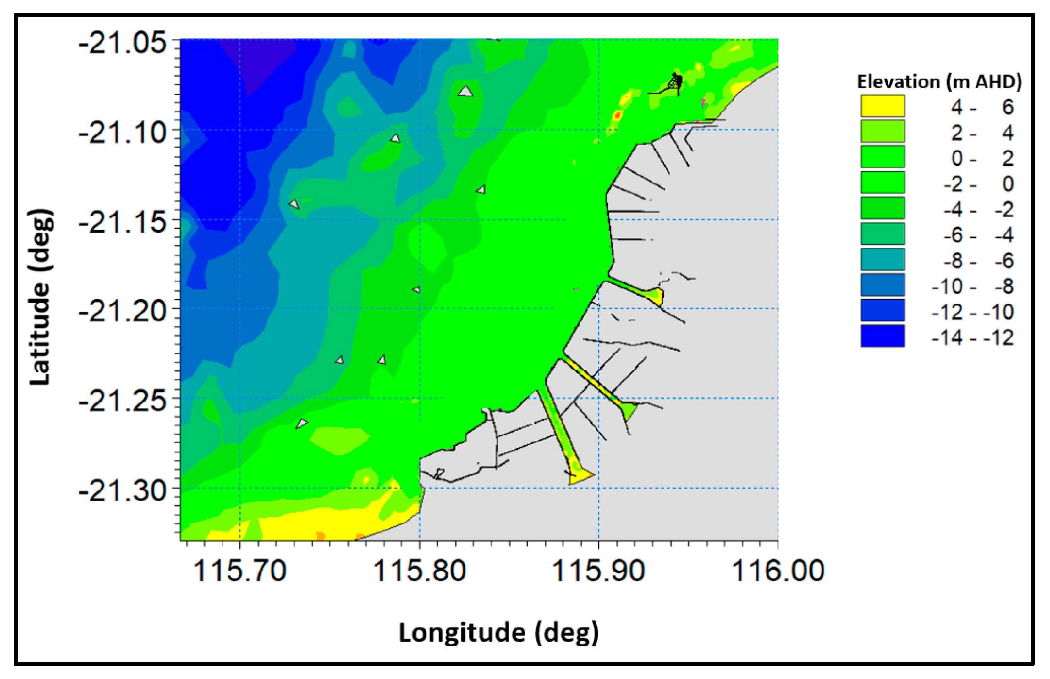
Figure 2.
Typical clay embankment for the Mardie Salt and Potash facility: (a) aerial view photograph courtesy BCI Minerals Limited; (b) modelled cross-section with reduced levels (RL) to meters above Australian Height Datum (AHD). Toe scour not tested.
Figure 2.
Typical clay embankment for the Mardie Salt and Potash facility: (a) aerial view photograph courtesy BCI Minerals Limited; (b) modelled cross-section with reduced levels (RL) to meters above Australian Height Datum (AHD). Toe scour not tested.
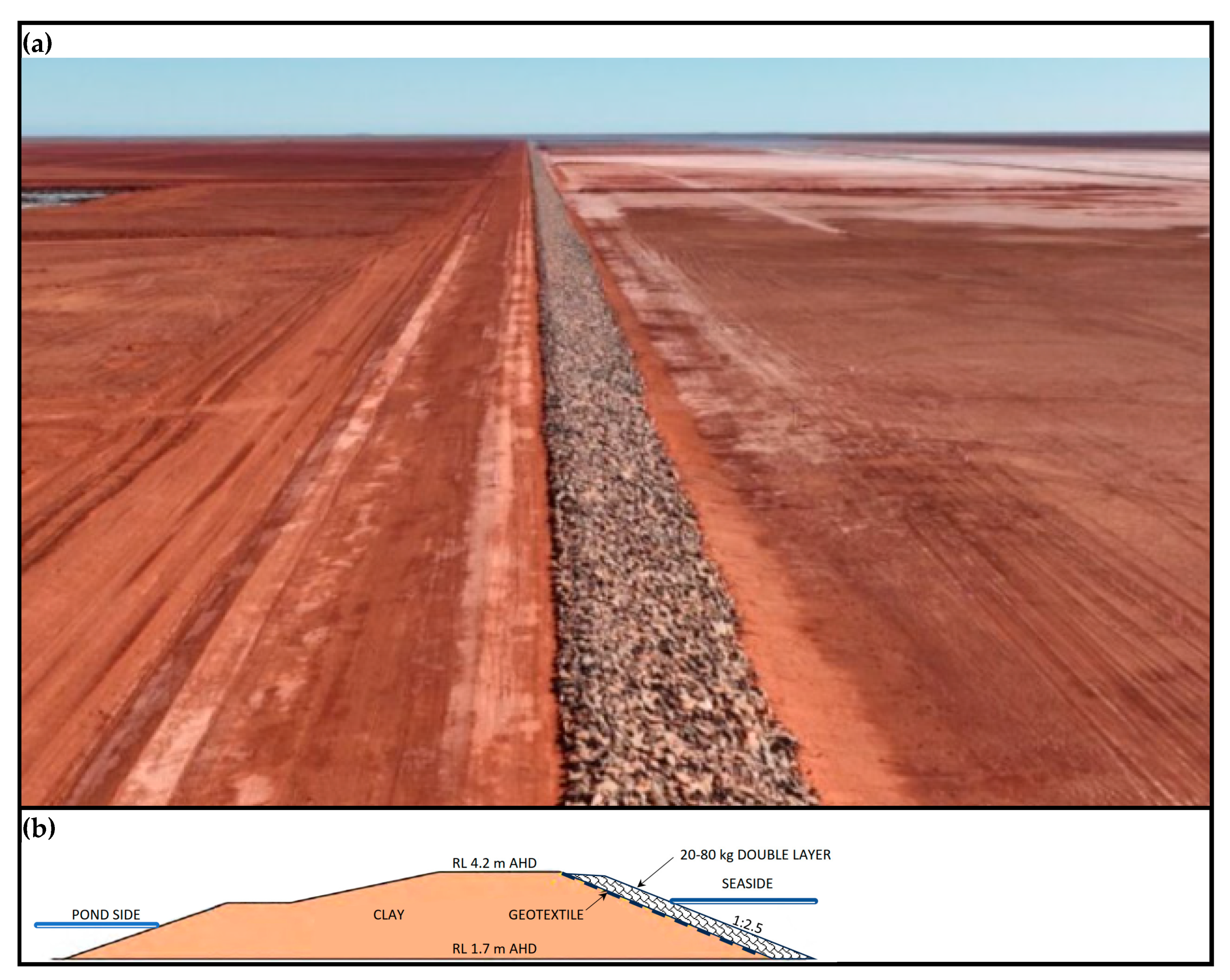
Figure 3.
Manly Hydraulics Lab (a) Section of 1 m flume; (b) Plan of 3 m wave flume.
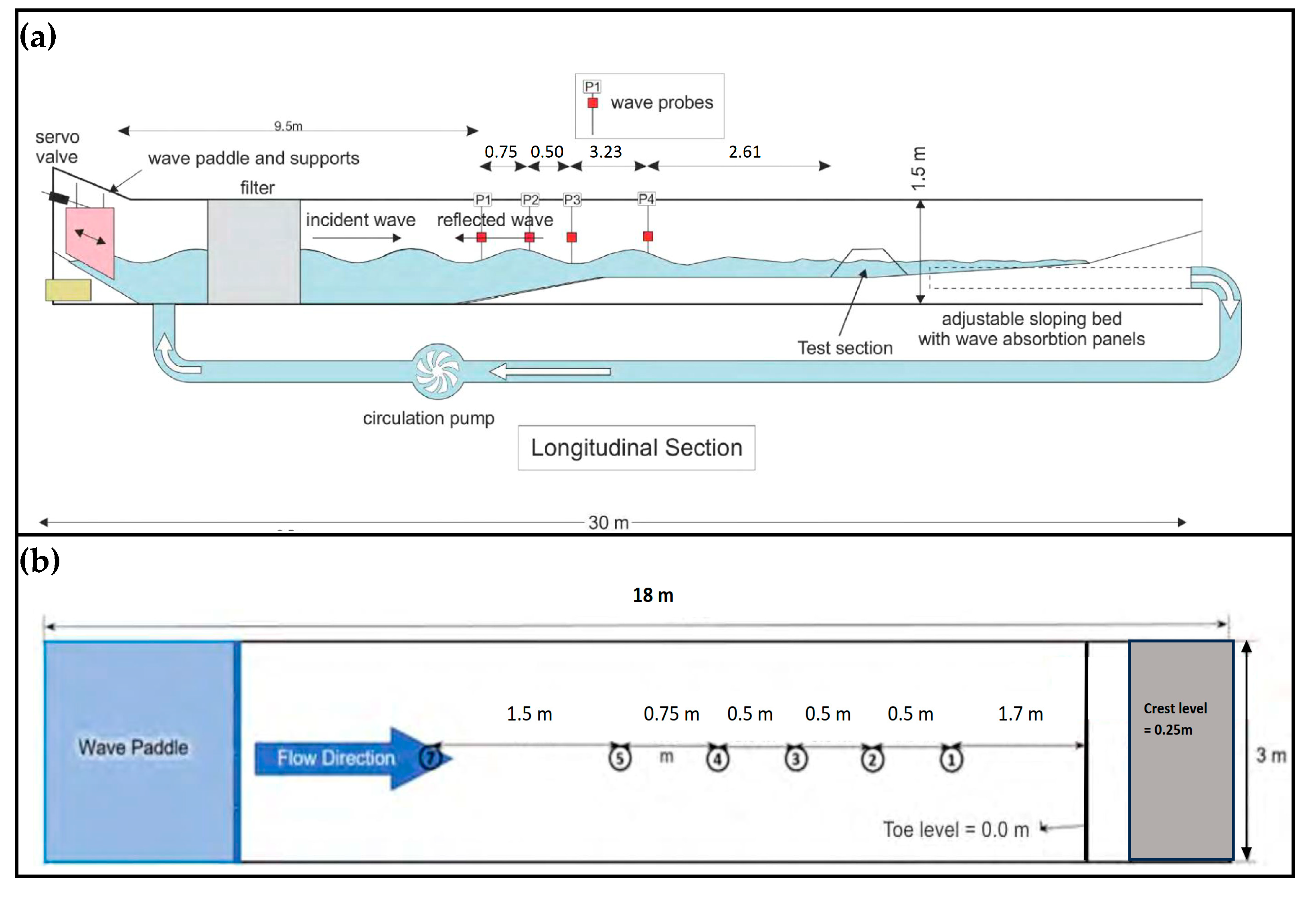
Figure 4.
(a) Mass distribution armour rock 1 m flume; (b) Rock as placed 1 m flume; (c) Mass distribution armour rock 3 m flume; (d) Rock as placed 3 m flume.
Figure 4.
(a) Mass distribution armour rock 1 m flume; (b) Rock as placed 1 m flume; (c) Mass distribution armour rock 3 m flume; (d) Rock as placed 3 m flume.
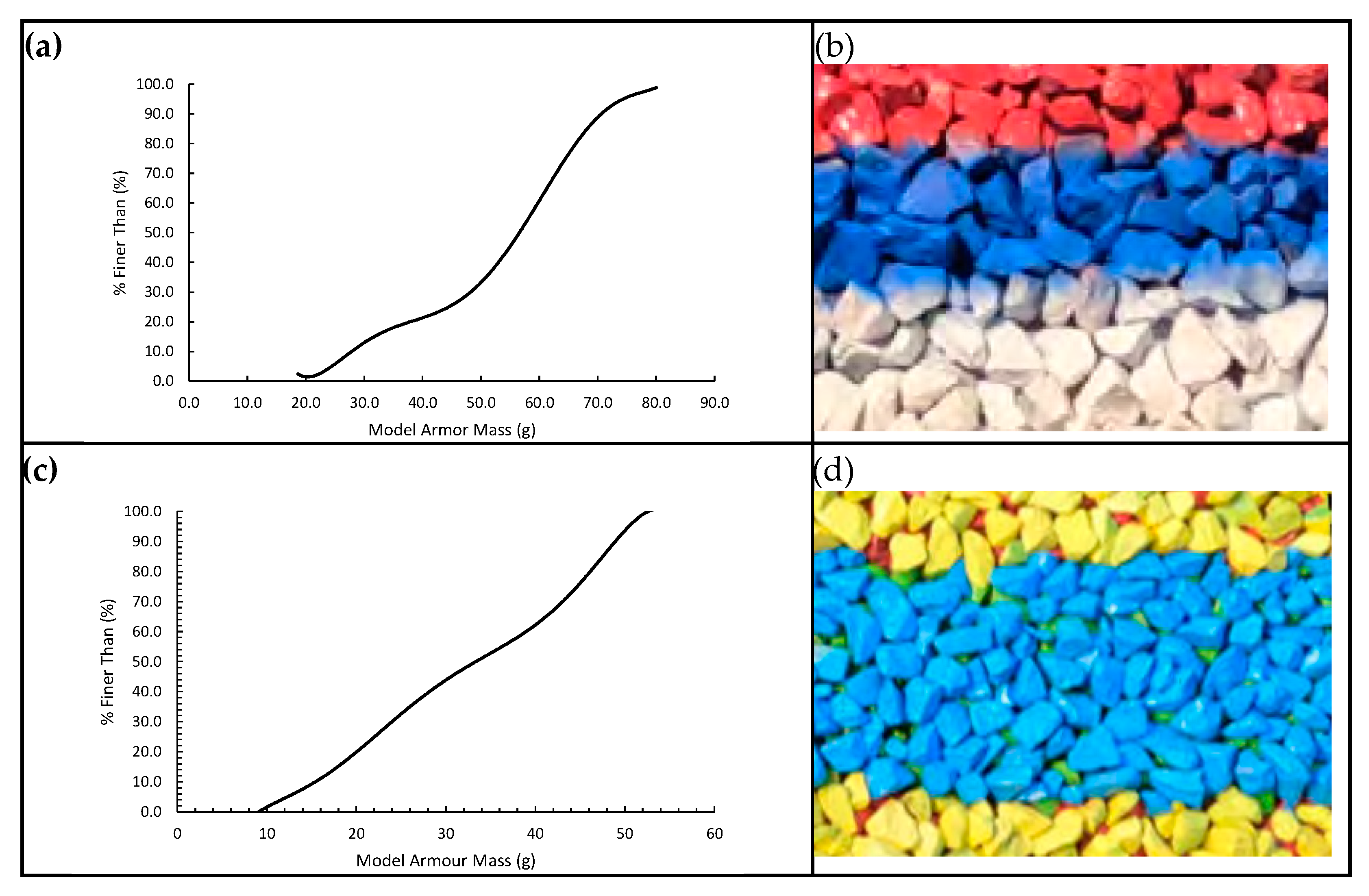
Figure 5.
Wave energy damage coefficient versus damage normalised by the square root of the number of zero-crossing waves for double layered standard rough angular rock armoured revetments with impermeable underlayers.
Figure 5.
Wave energy damage coefficient versus damage normalised by the square root of the number of zero-crossing waves for double layered standard rough angular rock armoured revetments with impermeable underlayers.
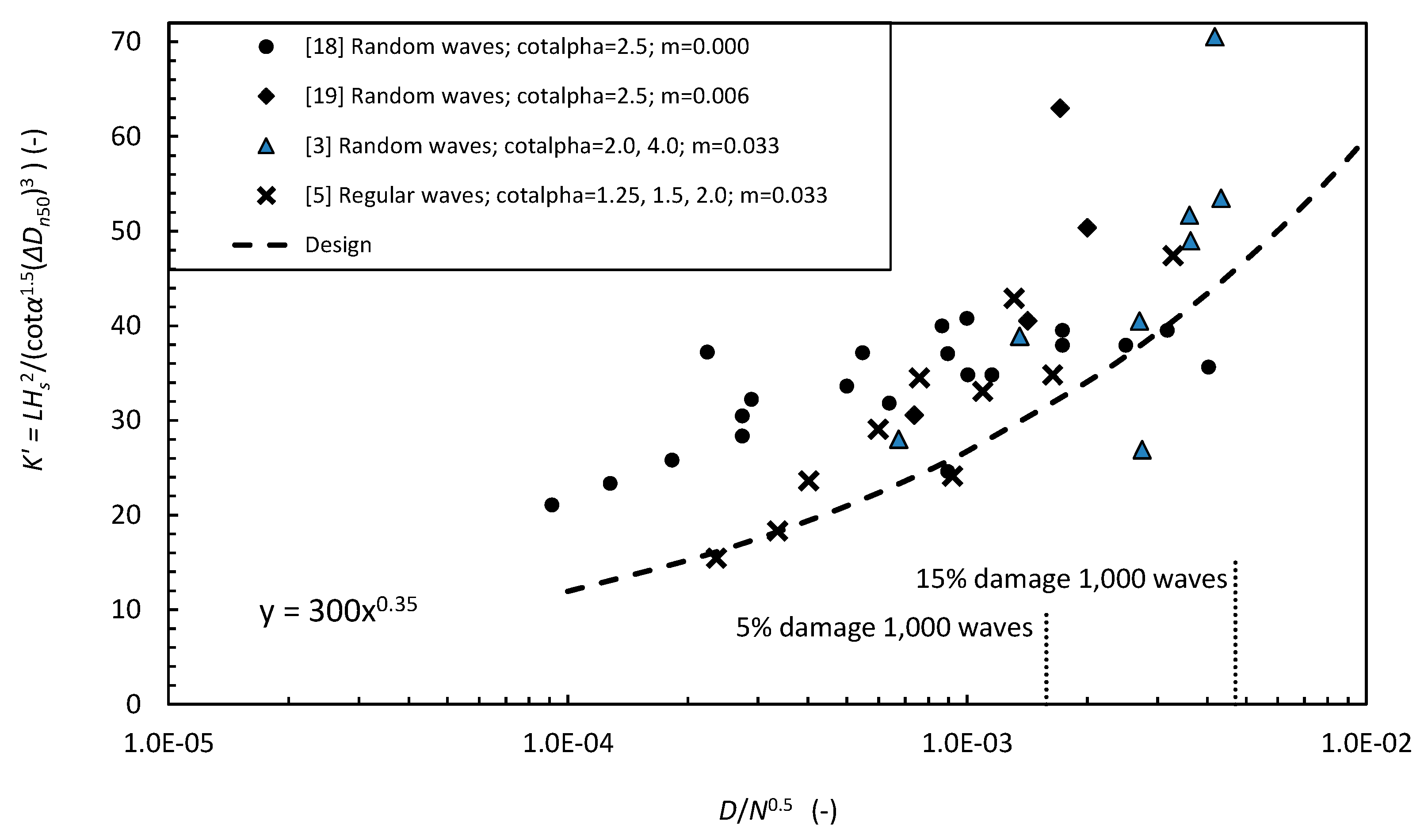
Figure 6.
Coefficients of Determination (R2) for the wave energy formula’s damage coefficient ()) and the modified Hudson formulae (, indicating greater coherence of the former with the flume data.
Figure 6.
Coefficients of Determination (R2) for the wave energy formula’s damage coefficient ()) and the modified Hudson formulae (, indicating greater coherence of the former with the flume data.
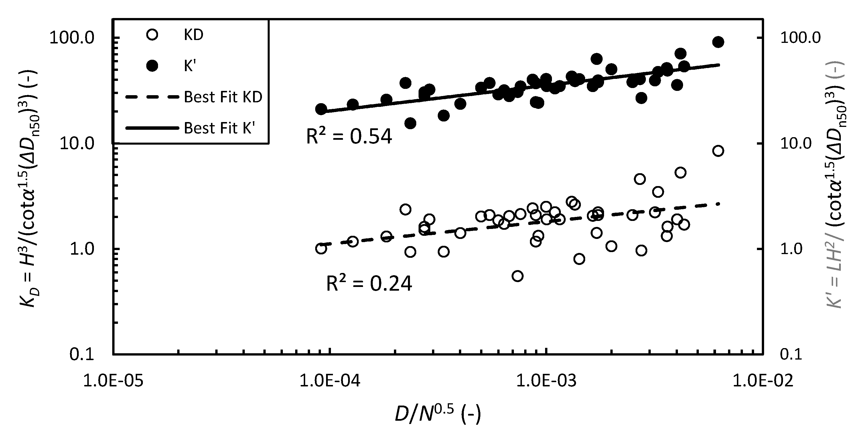
Figure 7.
Comparison of commonly used rock armour sizing formulae [1,2,6] with the proposed wave energy formula. Assumed: Tm = 0.7Tp [22]; S = 2; D = 2.5%; N = 1,000; m ≈ 0.025; Hs = 0.7htoe.
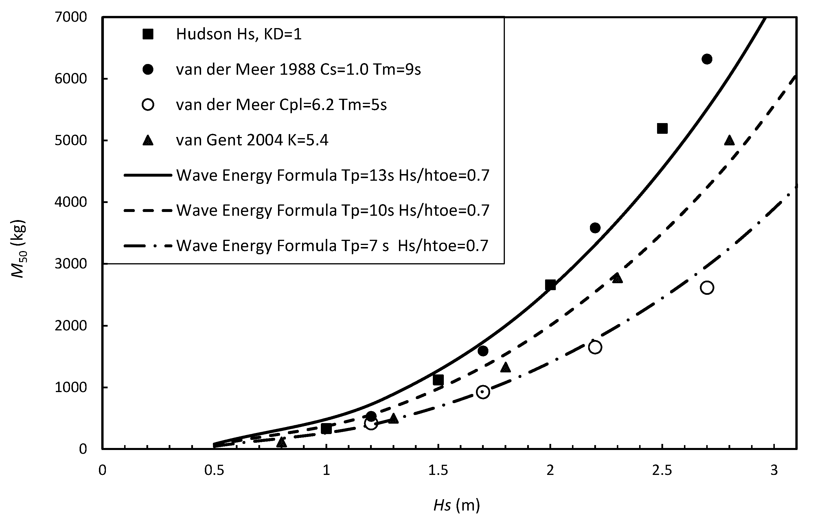
Figure 8.
Wave energy damage coefficient versus number of waves for 2%, 5%, 10% and 15% damage to a double layered rock armoured revetment with an impermeable underlayer. Arrows indicate the additional numbers of waves to failure for a range of initial design criteria, being 2%, 5% and 10% damage under 1,000 waves.
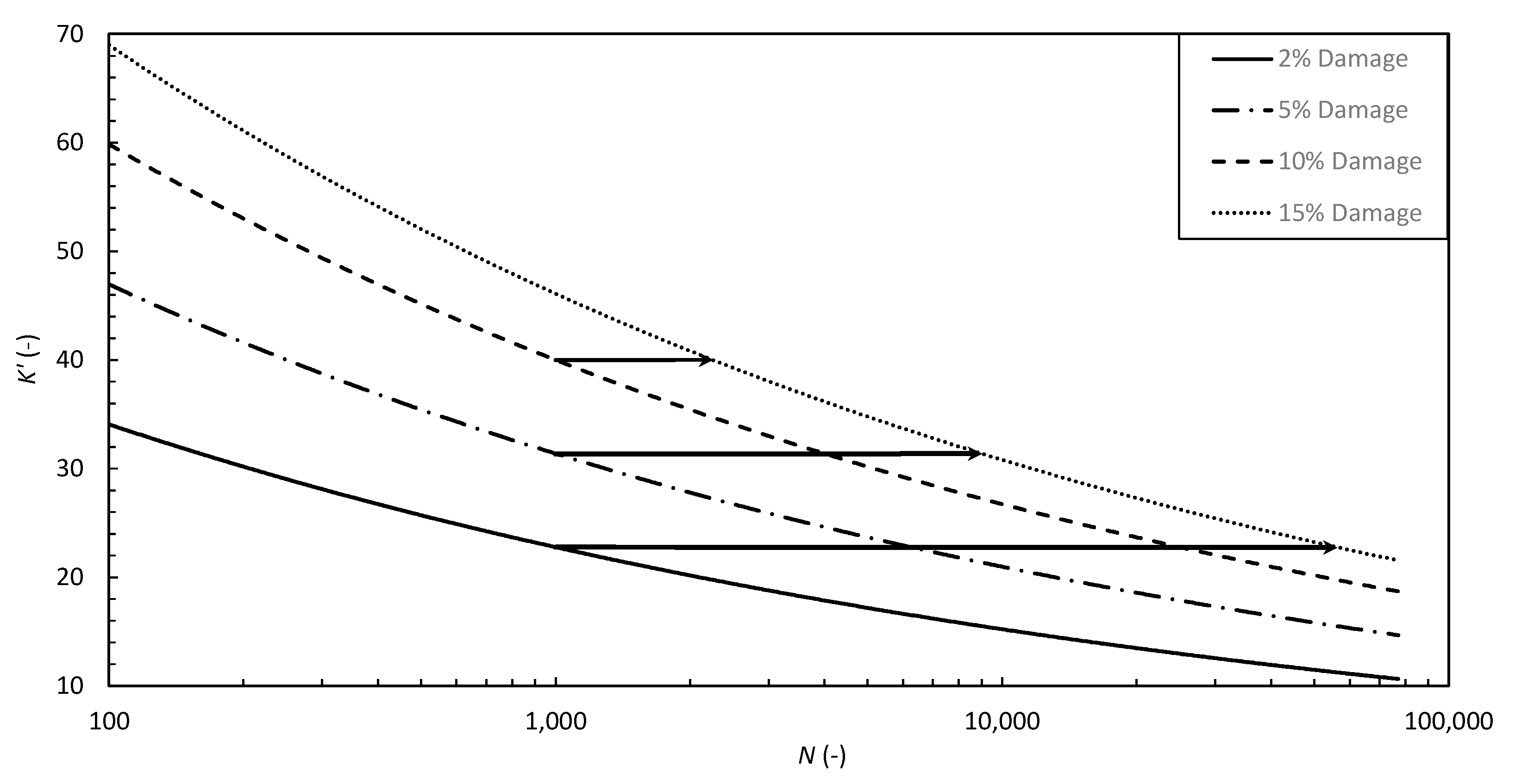

Table 1.
MHL 2023 flume test and reduced test data for damage from waves breaking onto double layered rock armoured revetments with impermeable underlayers.
Table 1.
MHL 2023 flume test and reduced test data for damage from waves breaking onto double layered rock armoured revetments with impermeable underlayers.
| Test Data | Reduced Test Data | |||||||
| Test | N | Hs | htoe | D | Hs/htoe | L | D/N0.5 | LHs2/(cotα1.5(ΔDn50)3) |
| No. | (-) | (m) | (m) | (%) | (-) | (m) | (-) | (-) |
| 1 m Flume Tp = 1.2 s M50 = 0.056 kg | ||||||||
| 27 | 3000 | 0.083 | 0.19 | 1.0 | 0.44 | 1.64 | 1.8E-04 | 25.8 |
| 28 | 3000 | 0.087 | 0.19 | 1.5 | 0.46 | 1.64 | 2.7E-04 | 28.4 |
| 29 | 3000 | 0.089 | 0.20 | 1.5 | 0.45 | 1.68 | 2.7E-04 | 30.4 |
| 30 | 3000 | 0.091 | 0.20 | 3.5 | 0.46 | 1.68 | 6.4E-04 | 31.8 |
| 31 | 3000 | 0.076 | 0.18 | 0.5 | 0.42 | 1.59 | 9.1E-05 | 21.1 |
| 32 | 3000 | 0.080 | 0.18 | 0.7 | 0.44 | 1.59 | 1.3E-04 | 23.3 |
| 33 | 3000 | 0.094 | 0.21 | 5.5 | 0.45 | 1.72 | 1.0E-03 | 34.8 |
| 34 | 3000 | 0.097 | 0.21 | 3.0 | 0.46 | 1.73 | 5.5E-04 | 37.2 |
| 35 | 3000 | 0.097 | 0.22 | 9.5 | 0.44 | 1.76 | 1.7E-03 | 37.9 |
| 36 | 3000 | 0.099 | 0.22 | 9.5 | 0.45 | 1.76 | 1.7E-03 | 39.5 |
| 38 | 300 | 0.094 | 0.21 | 2.0 | 0.45 | 1.72 | 1.2E-03 | 34.8 |
| 39 | 500 | 0.097 | 0.21 | 2.0 | 0.46 | 1.72 | 8.9E-04 | 37.1 |
| 40 | 100 | 0.097 | 0.22 | 2.5 | 0.44 | 1.76 | 2.5E-03 | 37.9 |
| 41 | 300 | 0.099 | 0.22 | 5.5 | 0.45 | 1.76 | 3.2E-03 | 39.5 |
| 42 | 500 | 0.094 | 0.22 | 9.0 | 0.43 | 1.76 | 4.0E-03 | 35.6 |
| 43 | 100 | 0.096 | 0.18 | 0.5 | 0.53 | 1.59 | 5.0E-04 | 33.6 |
| 44 | 300 | 0.094 | 0.18 | 0.5 | 0.52 | 1.59 | 2.9E-04 | 32.2 |
| 45 | 500 | 0.101 | 0.18 | 0.5 | 0.56 | 1.59 | 2.2E-04 | 37.2 |
| 46 | 100 | 0.103 | 0.20 | 1.0 | 0.52 | 1.68 | 1.0E-03 | 40.8 |
| 47 | 300 | 0.102 | 0.20 | 1.5 | 0.51 | 1.68 | 8.7E-04 | 40.0 |
| 48 | 500 | 0.080 | 0.20 | 2.0 | 0.40 | 1.68 | 8.9E-04 | 24.6 |
| 3 m Flume Tp = 2.5 s M50 = 0.034 kg | ||||||||
| 8 | 2000 | 0.053 | 0.14 | 3.3 | 0.38 | 2.93 | 7.4E-04 | 30.6 |
| 7 | 2000 | 0.060 | 0.15 | 6.4 | 0.40 | 3.03 | 1.4E-03 | 40.5 |
| 1 | 2000 | 0.066 | 0.16 | 9.0 | 0.41 | 3.13 | 2.0E-03 | 50.3 |
| 2 | 2000 | 0.073 | 0.17 | 7.7 | 0.43 | 3.23 | 1.7E-03 | 63.0 |
Table 2.
DELFT 2003 flume test and reduced data of damage from ~1,200 waves breaking onto double layered rock armoured revetments with impermeable underlayers.
Table 2.
DELFT 2003 flume test and reduced data of damage from ~1,200 waves breaking onto double layered rock armoured revetments with impermeable underlayers.
| Test Data | Reduced Test Data | |||||||
| Test | Hm0toe | htoe | N | Tp | Smeasured | Hm0toe/htoe | D/N0.5 | LHm0toe2/((ΔDn50)3cotα1.5) |
| No. | (m) | (m) | (-) | (s) | (-) | (-) | (-) | (-) |
| Structure 6 cotα = 2 | ||||||||
| 16 | 0.076 | 0.150 | 1,193 | 1.981 | 11.97 | 0.51 | 4.3E-03 | 33.5 |
| 17 | 0.075 | 0.150 | 1,216 | 1.863 | 10.13 | 0.50 | 3.6E-03 | 52.1 |
| 18 | 0.063 | 0.125 | 1,039 | 1.589 | 7.09 | 0.50 | 2.7E-03 | 31.6 |
| 19 | 0.070 | 0.125 | 1,286 | 2.471 | 10.34 | 0.56 | 3.6E-03 | 33.2 |
| Structure 7 cotα = 4 | ||||||||
| 7 | 0.130 | 0.250 | 1,267 | 2.525 | 17.76 | 0.52 | 6.2E-03 | 91.0 |
| 8 | 0.106 | 0.200 | 1,032 | 1.888 | 6.96 | 0.53 | 2.7E-03 | 40.5 |
| 9 | 0.111 | 0.200 | 1,333 | 3.000 | 12.20 | 0.56 | 4.2E-03 | 70.5 |
| 10 | 0.081 | 0.150 | 1,017 | 2.584 | 1.72 | 0.54 | 6.7E-04 | 28.0 |
| 11 | 0.088 | 0.150 | 1,068 | 3.038 | 3.55 | 0.59 | 1.4E-03 | 38.9 |
Table 3.
WRL 1973 Flume test and reduced data of damage from regular breaking waves onto a double layered rock armoured revetment with impermeable underlayers.
Table 3.
WRL 1973 Flume test and reduced data of damage from regular breaking waves onto a double layered rock armoured revetment with impermeable underlayers.
| Test Data | Reduced Test Data | |||||||
| cotα | T | hb | Hb | D | N | L | D/N0.5 | LHb2/((ΔDn50)3cotα1.5) |
| (-) | (s) | (m) | (m) | (%) | (-) | (m) | (-) | (-) |
| 2 | 1.3 | 0.075 | 0.068 | 1 | 1800 | 1.12 | 2.36E-04 | 15.5 |
| 2 | 1.37 | 0.095 | 0.085 | 3 | 2500 | 1.33 | 6.00E-04 | 29.1 |
| 2 | 1.35 | 0.100 | 0.090 | 6 | 3000 | 1.34 | 1.10E-03 | 33.1 |
| 2 | 1.35 | 0.115 | 0.104 | 18 | 3000 | 1.43 | 3.29E-03 | 47.4 |
| 1.5 | 1.31 | 0.075 | 0.067 | 2.2 | 3000 | 1.13 | 4.02E-04 | 23.6 |
| 1.5 | 1.37 | 0.084 | 0.077 | 3.4 | 2000 | 1.24 | 7.60E-04 | 34.5 |
| 1.5 | 1.35 | 0.094 | 0.084 | 8.3 | 4000 | 1.29 | 1.31E-03 | 42.9 |
| 1.25 | 1.36 | 0.060 | 0.053 | 1.3 | 1500 | 1.04 | 3.36E-04 | 18.3 |
| 1.25 | 1.34 | 0.067 | 0.060 | 6.5 | 5000 | 1.09 | 9.19E-04 | 24.1 |
| 1.25 | 1.35 | 0.077 | 0.069 | 11.6 | 5000 | 1.17 | 1.64E-03 | 34.8 |
Table 3.
Limits of application of the adopted flume data.
| Parameter | Symbol | MHL 2023 | Delft 2003 | WRL 1973 |
| Revetment slope | cotα | 2.5 | 2.0, 4.0 | 1.25, 1.5, 2.0 |
| Median rock mass | M50 | 0.035,0.056 kg | 0.047 kg | 0.064 kg |
| Rock Grading | Dn85/Dn15 | 1.3, 1.4 | 1.4 | 1.3 |
| Seabed slope | m | 0.006, 0.000 | 0.033 | 0.033 |
| Wave Conditions | (-) | Random | Random | Regular |
| Wave period | Tp | 1.2 s, 2.5 s | 1.5 - 3.0 s | 1.3-1.4 |
| Wave height/depth | Hstoe/htoe | 0.42 - 0.46 | 0.50 - 0.59 | 0.89-0.91 |
| Number of waves | N | 100, 300, 500, 2,000, 3,000 |
1,100 - 1,300 | 10,000 |
Disclaimer/Publisher’s Note: The statements, opinions and data contained in all publications are solely those of the individual author(s) and contributor(s) and not of MDPI and/or the editor(s). MDPI and/or the editor(s) disclaim responsibility for any injury to people or property resulting from any ideas, methods, instructions or products referred to in the content. |
© 2025 by the authors. Licensee MDPI, Basel, Switzerland. This article is an open access article distributed under the terms and conditions of the Creative Commons Attribution (CC BY) license (http://creativecommons.org/licenses/by/4.0/).
Copyright: This open access article is published under a Creative Commons CC BY 4.0 license, which permit the free download, distribution, and reuse, provided that the author and preprint are cited in any reuse.


