Submitted:
10 February 2025
Posted:
10 February 2025
You are already at the latest version
Abstract
Conducting survey and timely obtain of satellite status, especially for high-value GEO targets, is of great significance for Space Traffic Management. This article proposes an approach for patrolling Inclined Geosynchronous Orbit (IGSO) targets based on crossing points and spiral rings, which including six steps: (1) calculate the crossing position and crossing time of the IGSO targets; (2) design the spiral trajectory that satisfies desired patrol time; (3) divide IGSO targets into regions based on dichotomy approach; (4) calculate the bidirectional longitude drift rate within each region; (5) determine the starting position of patrol for each region; (6) determine the transfer trajectory for each region. On this basis, the proposed approach is analyzed and validated in detail. The results showed that the patrol orbit can effectively achieve patrol all of IGSO targets, with a period of no more than 40 days and an energy consumption of no more than 0.04km/s. And, the total energy consumption of a single patrol cycle in all regions shall not exceed 0.4km/s.
Keywords:
1. Introduction
2. Materials and Methods
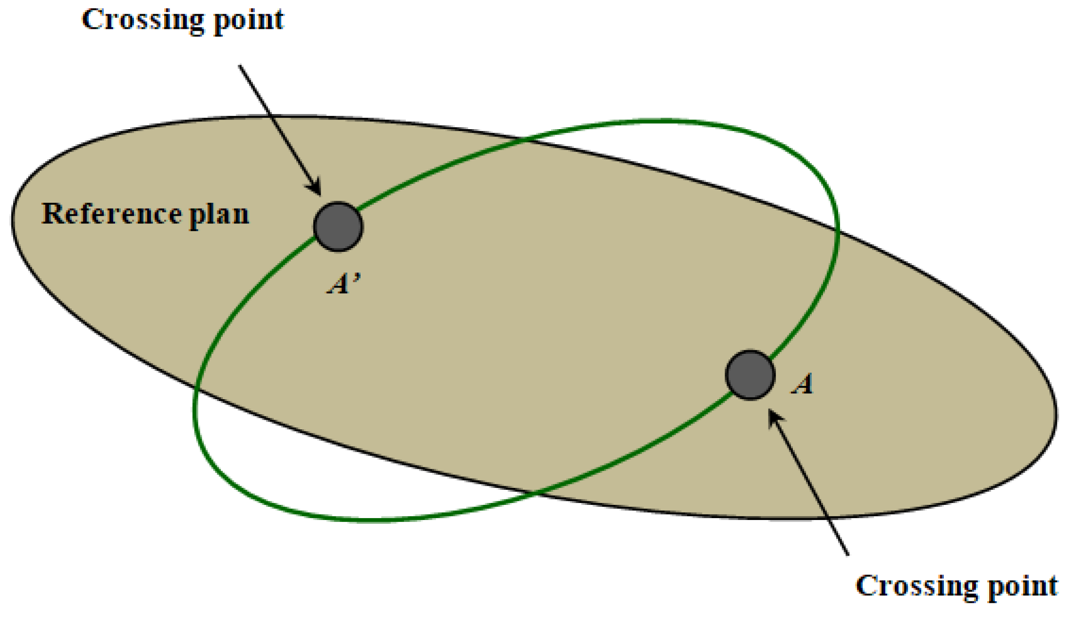
2.1. Calculate the Crossing Position and Crossing Time of the igso Targets
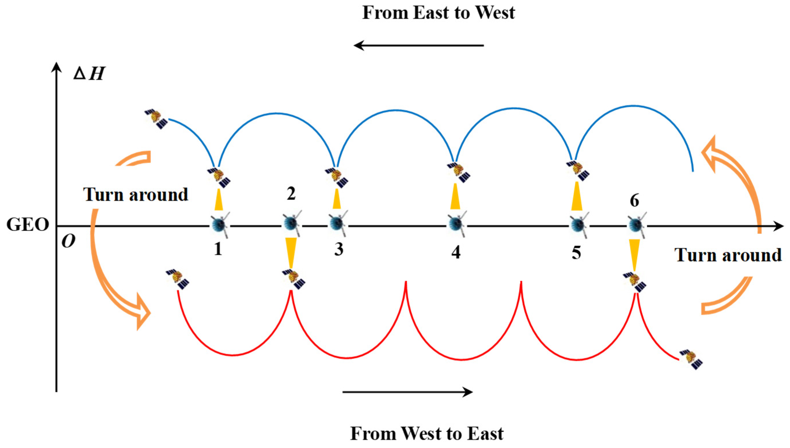
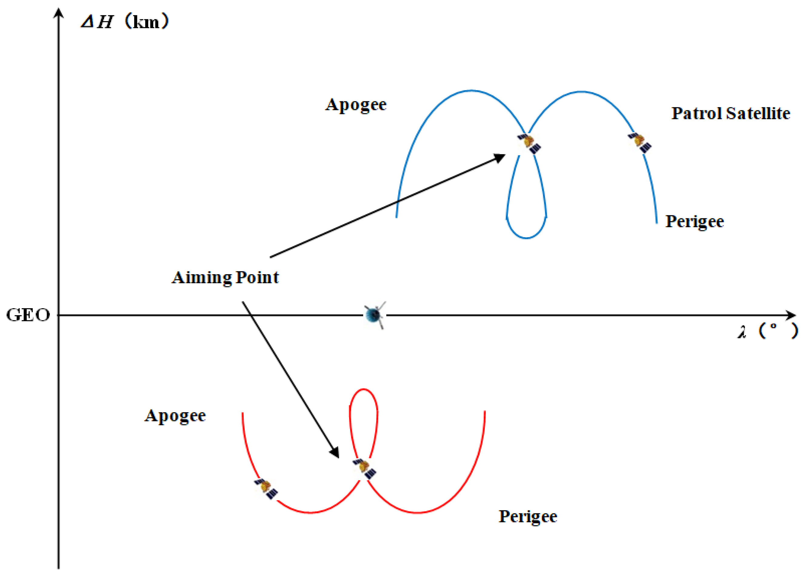
2.2. Design the Spiral Trajectory That Satisfies Desired Patrol Time
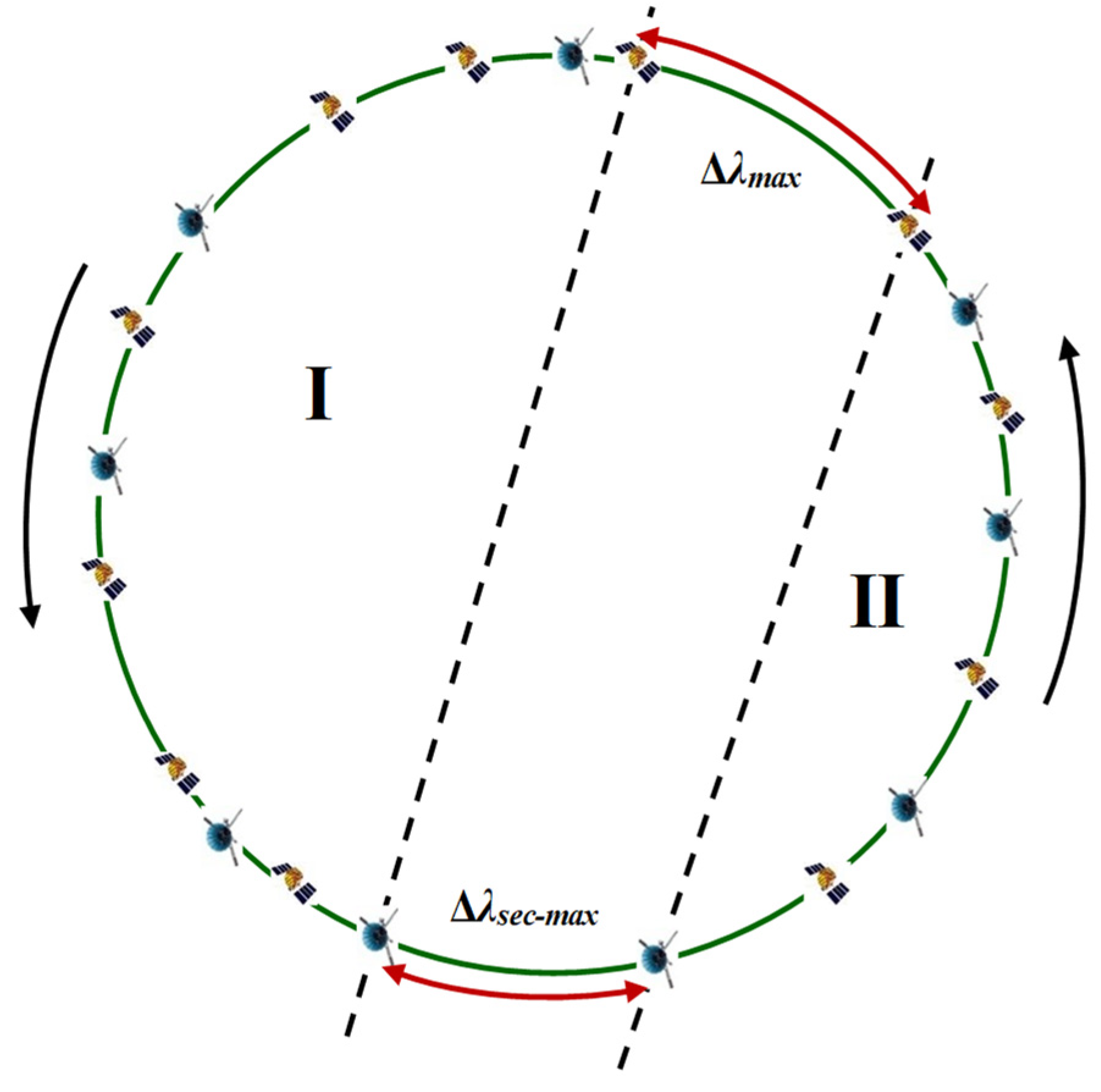
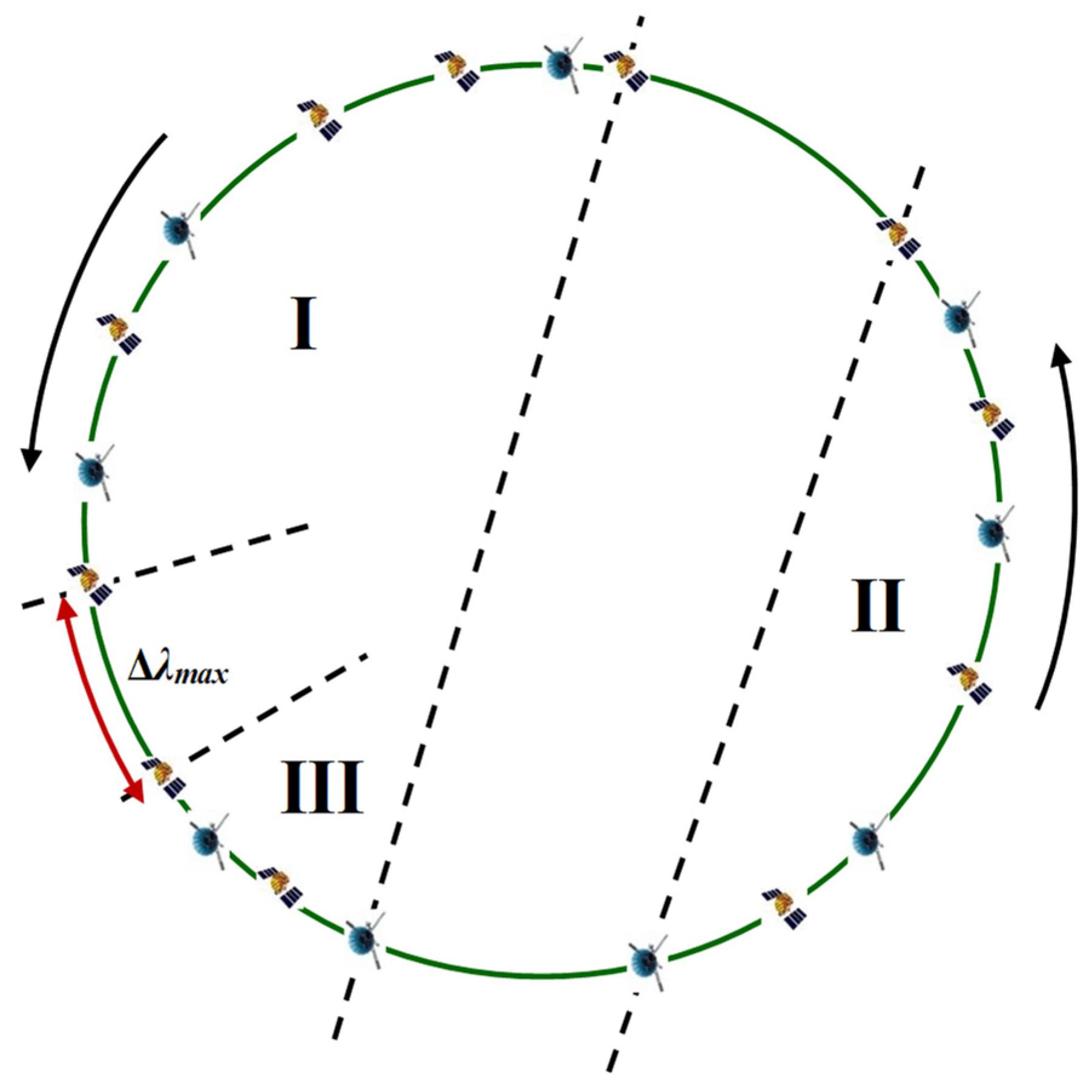
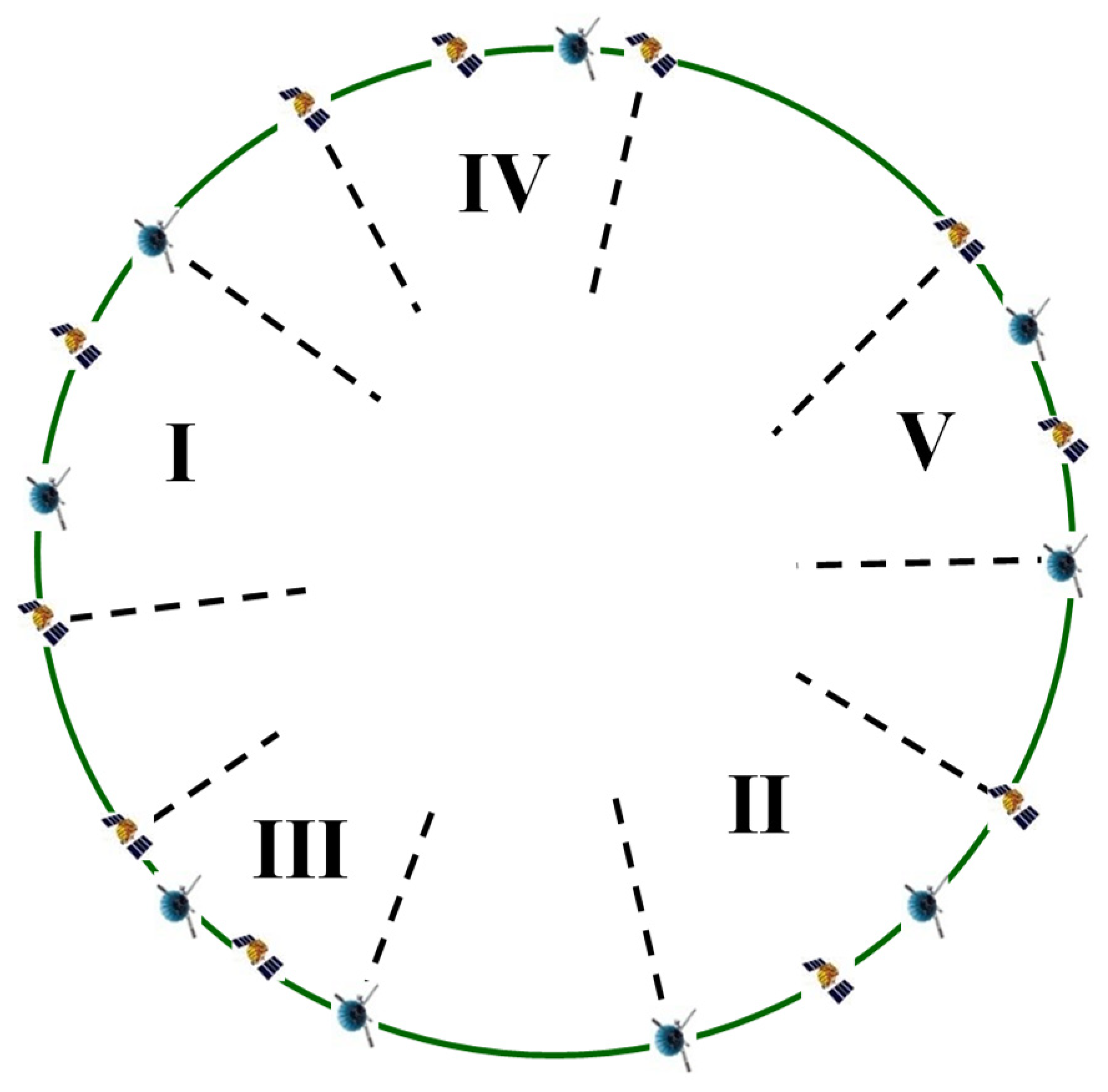
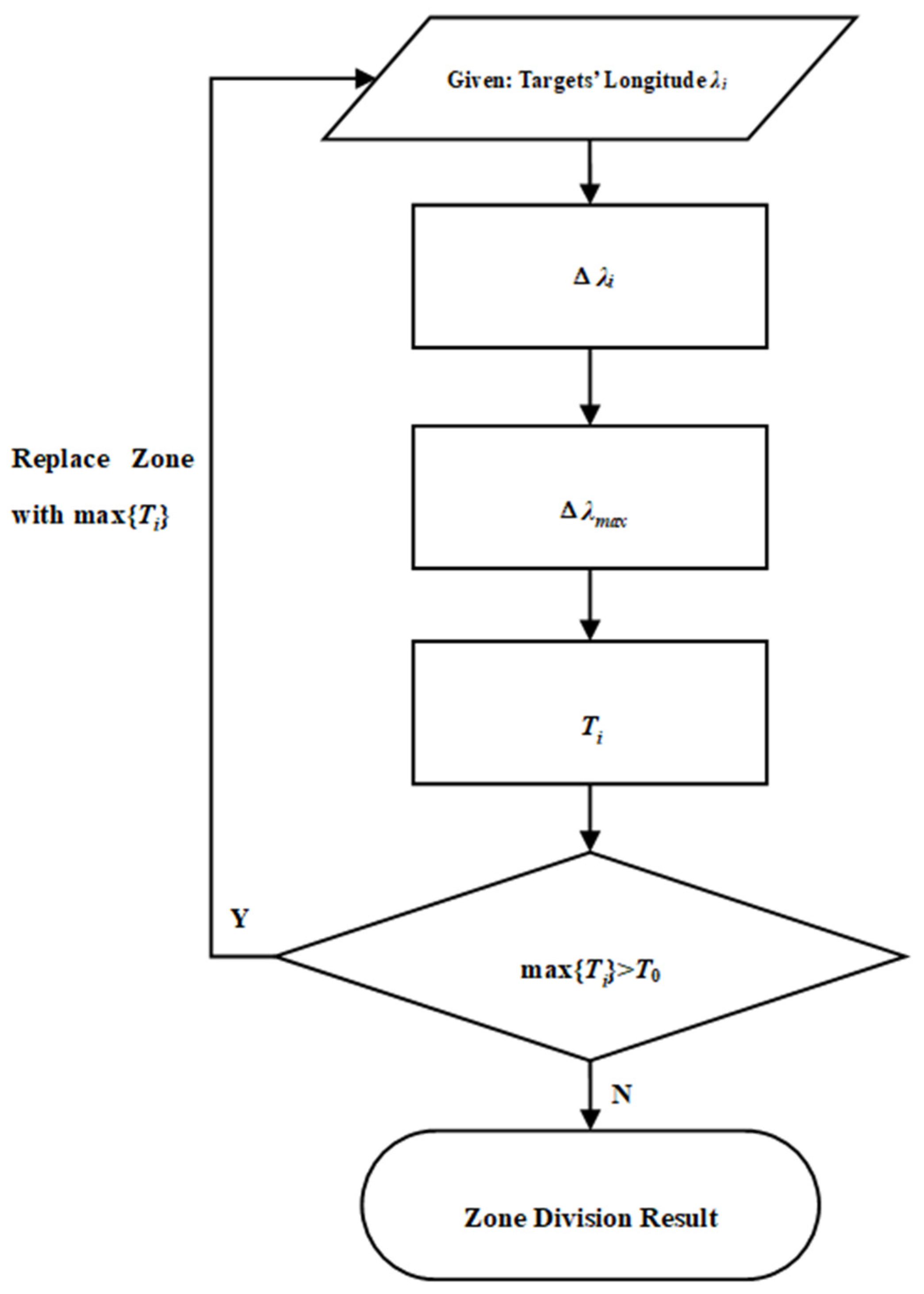
2.3. Divide IGSO Targets into Regions Based on Dichotomy Approach
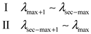

2.4. Calculate the Bidirectional Longitude Drift Rate within Each Region
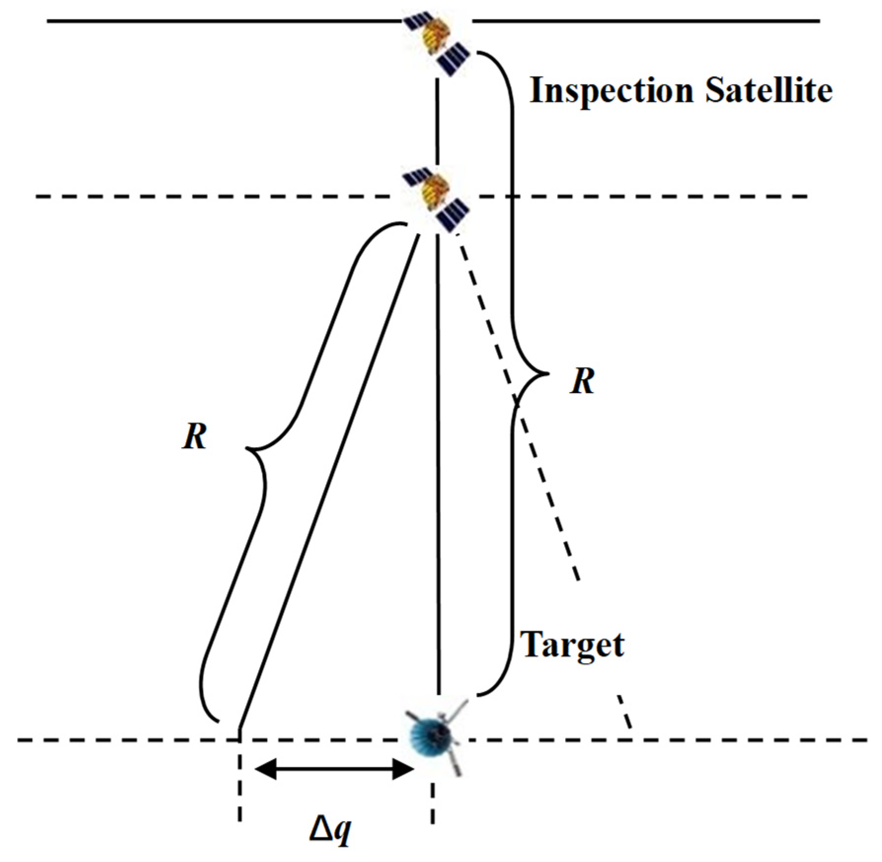
2.5. Determine the Starting Position of Patrol for Each Region
2.6. Determine the Transfer Trajectory for Each Region
3. Results
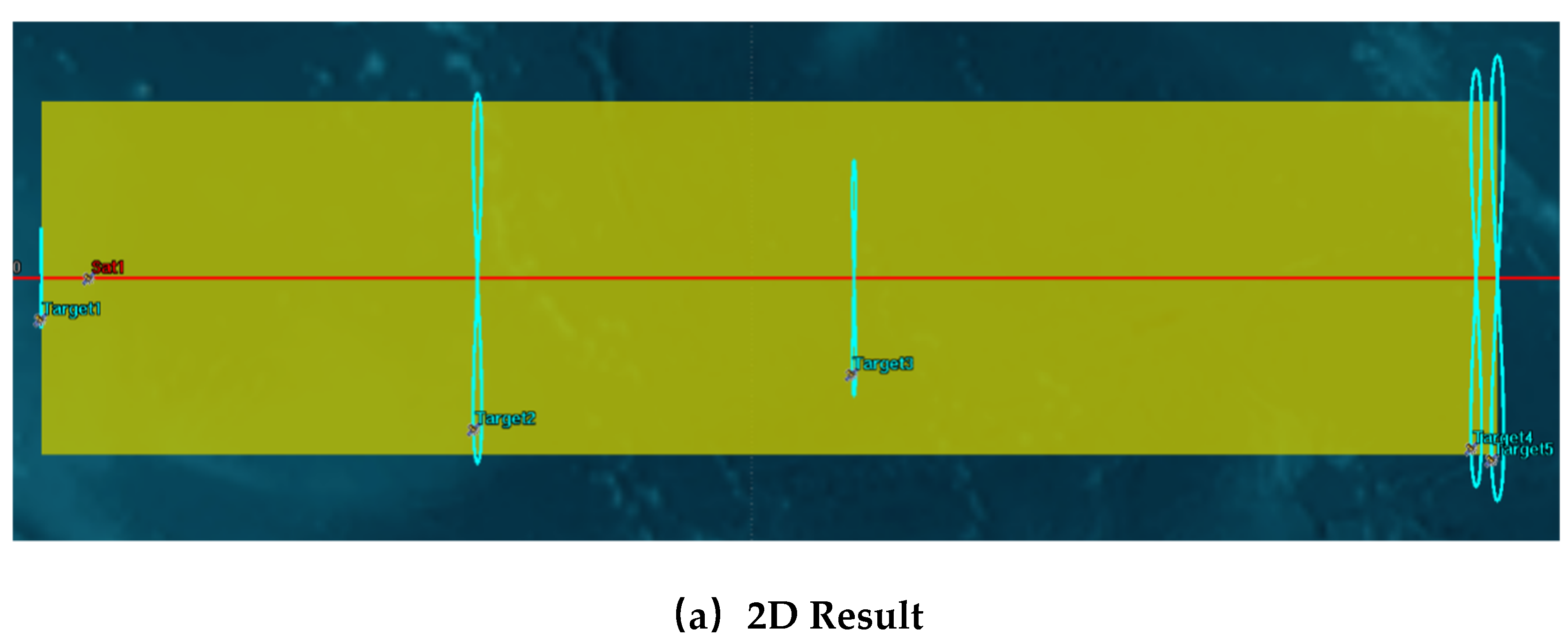
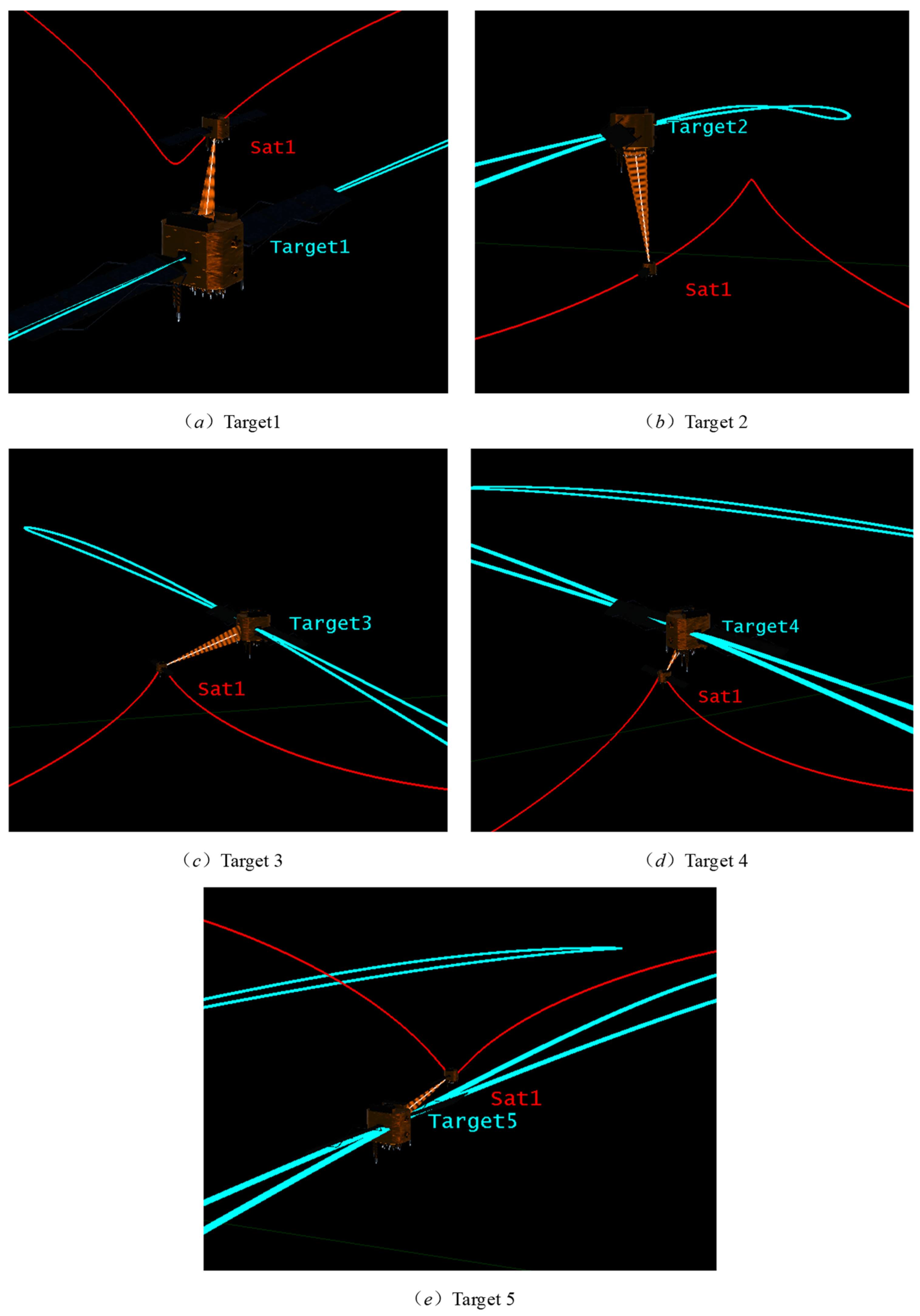
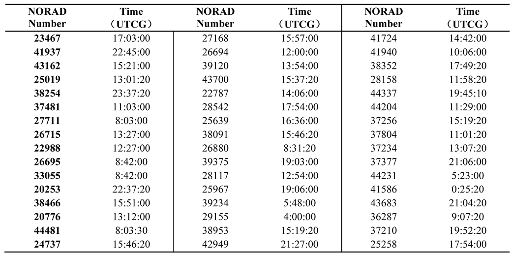
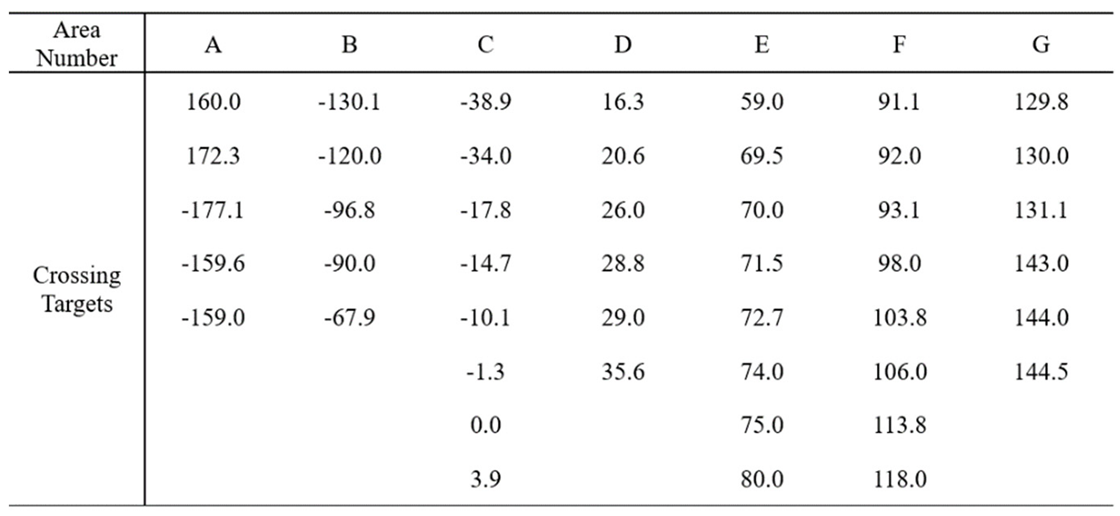
3.1. Calculate the Crossing Position and Crossing Time of the igso Targets
3.2. Design the Spiral Trajectory That Satisfies Desired Patrol Time
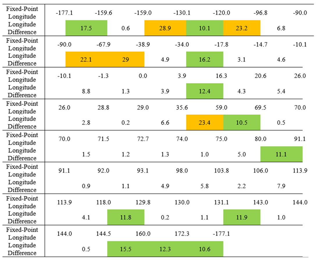
3.3. Divide IGSO Targets into Regions Based on Dichotomy Approach
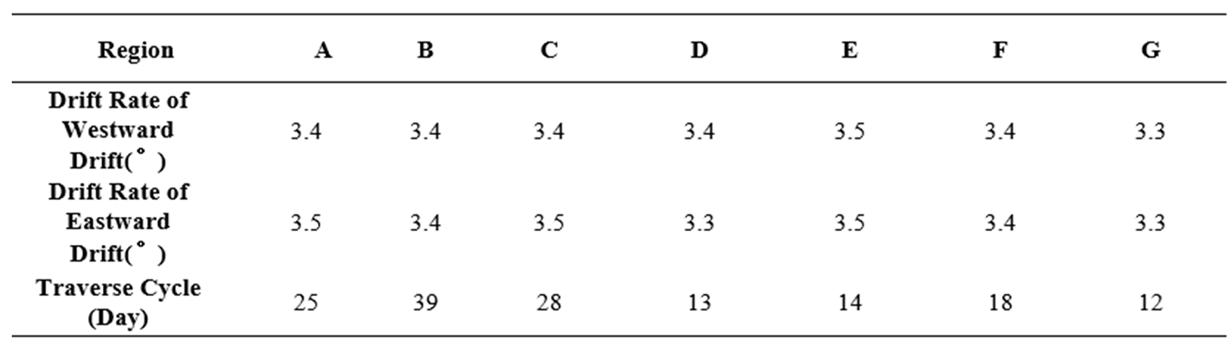
3.4. Calculate the Bidirectional Longitude Drift Rate Within Each Region
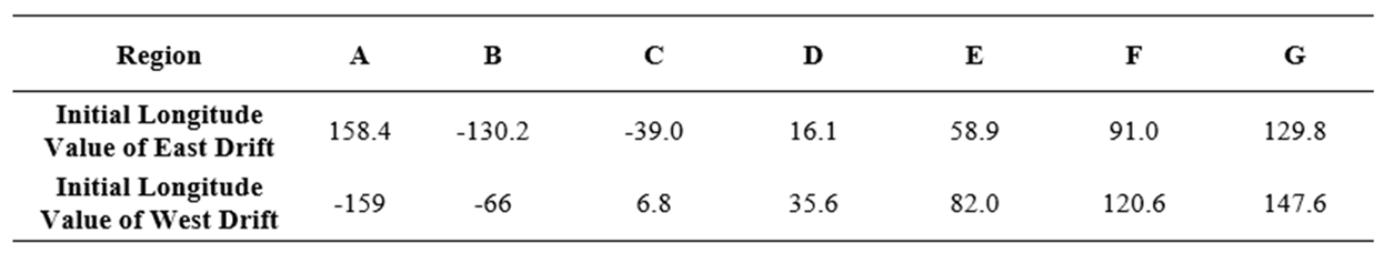
3.5. Determine the Starting Position of Patrol for Each Region
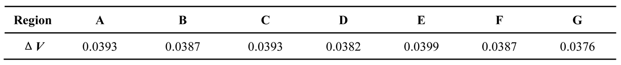
3.6. Determine the Transfer Trajectory for Each Region
4. Discussion
5. Conclusions
6. Patents
References
- Quan Haofang, Li Xiaolong. Preliminary Research on Space Traffic Management Standards System [J]. Space Debris Research, 2021, Volume 21 (81): 50-57.
- Duan Feng. Research on the Shift from Space Traffic Management to Space Traffic Coordination in the United States [J]. Space Debris Research, 2022, Volume 22 (83): 66-71.
- Yao Wenduo, Feng Shuxing, Chen Lingyun. Study on the Development of Space Traffic Management[J]. Aerospace China, 2021(3): 49-52.
- Feng Shuxing, Yao Wenduo, Chen Lingyun. Discussion on the Framework of Space Traffic Management System[J]. Aerospace China, 2021(9): 38-43.
- Space Debris Mitigation Guidelines. IADC, Revision 2, 2020.
- ESA's Annual Space Environment Report. ESA, 2024.
- https://www.ucsusa.org/resources/satellite-database.
- Haijun Shen and Panagiotis Tsiotras. Optimal Scheduling for Servicing Multiple Satellites in a Circular Constellation[C]. AIAA/AAS Astrodynamics Specialist Conference and Exhibit, Monterey, California, August 5~8,2002.
- Alfriend K T, Creamer N G, Lee D J. Optimal Servicing of Geosynchronous Satellites[J]. Journal of Guidance Control and Dynamics, 2006, 29(1):203-206.
- Zhou Y, Yan Y, Huang X, et al. Mission planning optimization for multiple geosynchronous satellites refueling[J]. Advances in Space Research, 2015, 56(11):2612-2625.
- Xu Yanli, Zhang Yasheng. Design and Simulation of Spiral Cruise Orbit[C]. System Simulation Technology and Its Application.
- Zheng Letian, Xu Yanli, Zhu Dongjun. Cruise orbit design for multiple geostationary orbit targets[J]. Aerospace Control and Application, 2016, 42(5):37-41.
- Bo X, Feng Q. Research on constellation refueling based on formation flying[J]. Acta Astronautica, 1987, 68(11-12):1987-1995.
- Huang, Xu, Yan, et al. Optimal scheduling of multiple geosynchronous satellites refueling based on a hybrid particle swarm optimizer[J]. Aerospace Science & Technology, 2015, 47:125-134.
- Madakat D, Morio J, Vanderpooten D. Biobjective planning of an active debris removal mission[J]. Acta Astronautica, 2013, 84(MAR.-APR.):182-188.
- Du B, Zhao Y, Dutta A, et al. Optimal scheduling of multisatellite refueling based on cooperative maneuver[J]. Advances in Space Research, 2015, 55(12):2808-2819.
- Jackson B. Minimum energy maneuvering strategies for multiple satellite inspection missions[C]. Aerospace Conference, IEEE, 2005.
- Zhang J, Parks G T, Luo Y Z, et al. Multisatellite Refueling Optimization Considering the J2 Perturbation and Window Constraints[J]. Journal of Guidance Control & Dynamics, 2014, 37(1):111-122.
- Zhou Y, Yan Y, Huang X, et al. Optimal scheduling of multiple geosynchronous satellites refueling based on a hybrid particle swarm optimizer[J]. Aerospace Science and Technology, 2015, 47:125-134.
- Zhang T J, Shen H X, Wang B H, et al. Optimal scheduling for location geosynchronous satellites refueling problem[J]. Acta Astronautica, 2019.
- Haijun Shen and Panagiotis Tsiotras. Peer-to-Peer Refueling for Circular Satellite Constellations[J]. Journal of Guidance Control & Dynamics, 2005.
- Salazar A, Tsiotras P. An auction algorithm for allocating fuel in satellite constellations using peer-to-peer refueling[J]. 2006.
- Chen X Q, Yu J. Optimal mission planning of GEO on-orbit refueling in mixed strategy[J]. Acta Astronautica, 2017, 133(apr.):63-72.
- Atri Dutta∗, Panagiotis Tsiotras†. Asynchronous optimal mixed P2P satellite refueling strategies[J]. The Journal of the Astronautical sciences, 2006, 54(3-4):543-565.
- Xiao Dongdong, Xu Bo, Gao Youtao, etc Optimization of Supply Orbit for Heterogeneous Constellations Based on Companion Flight Mode [J] Chinese Science: Physics, Mechanics, Astronomy, 2012 (12): 67-77.
- Xiao Dongdong, Zhu Qinghua, Zu Liye Research on Multi Supply Tasks of Heterogeneous Constellations Based on Accompanying Flight Mode [J] Shanghai Aerospace, 2016, 33 (02): 9-14.
- Zhang T J, Shen H X, Wang B H, et al. Optimal scheduling for location geosynchronous satellites refueling problem[J]. Acta Astronautica, 2019, 163:264-271.
- Yu J, Yu Y G, Hao D, et al. Biobjective mission planning for geosynchronous satellites on-orbit refueling[J]. Proceedings of the Institution of Mechanical Engineers, 2019, 233(2):686-697.
- C. Prodhon, C. Prins. A survey of recent research on location-routing problems[J]. European Journal of Operational Research, 2014, 238:1–17.
- Haijun Shen and Panagiotis Tsiotras. Peer-to-Peer Refueling for Circular Satellite Constellations[J]. Journal of Guidance Control & Dynamics, 2005, 28(6):1220-1238.
- Salazar A, Tsiotras P. An auction algorithm for allocating fuel in satellite constellations using peer-to-peer refueling[C]. American Control Conference. IEEE, 2006.
- B.L. Rui, C. Ferreira, B.S. Santos. A simple and effective evolutionary algorithm for the capacitated location routing problem[J]. Computers & Operation Research. 2016, 70: 155–162.
- Dutta A, Tsiotras P. An Egalitarian Peer-to-Peer Satellite Refueling Strategy[J]. Journal of Satellite and Rockets, 2008, 45(3):608-618.
- Dutta, A, and Tsiotras, P. Greedy Random Adaptive Search Procedure for Optimal Scheduling of P2P Satellite Refueling[C] AAS/AIAA Space Flight Mechanics Meeting, American Astronautical Society Paper 07-150, Jan. 2007.
- Dutta, A, and Tsiotras, P. Network Flow Formulation for an Egalitarian P2P Refueling Strategy[C] AAS/AIAA Space Flight Mechanics Meeting, American Astronautical Society Paper 07-151, Jan. 2007.
- Chen X Q, Yu J. Optimal mission planning of GEO on-orbit refueling in mixed strategy[J]. Acta Astronautica, 2017, 133(4):63-72.
- Bai Xiaozheng, Xi Xiaoning Realizing close proximity between a single spacecraft and multiple satellites in a constellation without the need for orbit changes [J] Journal of Astronautics, 2005, 026 (0z1): 114-116.
- Wang Wei, Huang Wende, Fu Xiaofeng, etc The close-up approach of a single spacecraft to multiple satellites in the Walker constellation [J] Journal of Space Science, 2005, 25 (006): 547-551.
- Tang Rong, Wang Wei, Fu Xiaofeng Orbit selection and optimization for approaching multiple Walker constellation satellites [J] Computer Simulation, 2008 (04): 59-62.
- Zhang Jing, Xi Xiaoning, Wang Wei Sufficient conditions and characteristic analysis for a single spacecraft to rendezvous with multiple stars in the Walker constellation without the need for orbit change [J] Journal of National University of Defense Technology, 2010, 32 (6): 87-92.
- Zhang Jing, Wang Wei, Xi Xiaoning Approach orbit design for deviated Walker constellation satellites [J] Journal of Astronautics, 2008, 29 (4): 1200-1204.
- Zhang Jing, Wu Meiping, Fu Xiaofeng The Application of Genetic Algorithm in Optimization of Multi star Approach Orbits in Constellations [J] Journal of Space Science, 2012, 32 (001): 99-105.
- Yang Yidai Research on Satellite Traverse Target Dynamics and Orbit Design Problems [D] Harbin Institute of Technology, 2012.
- Mana. Fuel optimal orbit design for satellite constellation traversal in limited thrust mode [D] Harbin Institute of Technology, 2017.
- Zhang Yasheng, Zhou Haijun A multi-objective rendezvous orbit design method based on crossing points [J] Modern Defense Technology, 2013 (05): 13-17.
- Li Yuanfei, Zhang Yasheng Design of non-coplanar multi-objective rendezvous orbits based on crossing points [J] Aerospace Control, 2013, 31 (6): 66-70.
- Zhang Y , Xu Y , Zhou H .Theory and Design Methods of Special Space Orbits[M].Springer Singapore,2017.


 |
 |
 |
 |
 |
 |
 |
Disclaimer/Publisher’s Note: The statements, opinions and data contained in all publications are solely those of the individual author(s) and contributor(s) and not of MDPI and/or the editor(s). MDPI and/or the editor(s) disclaim responsibility for any injury to people or property resulting from any ideas, methods, instructions or products referred to in the content. |
© 2025 by the authors. Licensee MDPI, Basel, Switzerland. This article is an open access article distributed under the terms and conditions of the Creative Commons Attribution (CC BY) license (http://creativecommons.org/licenses/by/4.0/).


