Submitted:
08 February 2025
Posted:
08 February 2025
You are already at the latest version
Abstract
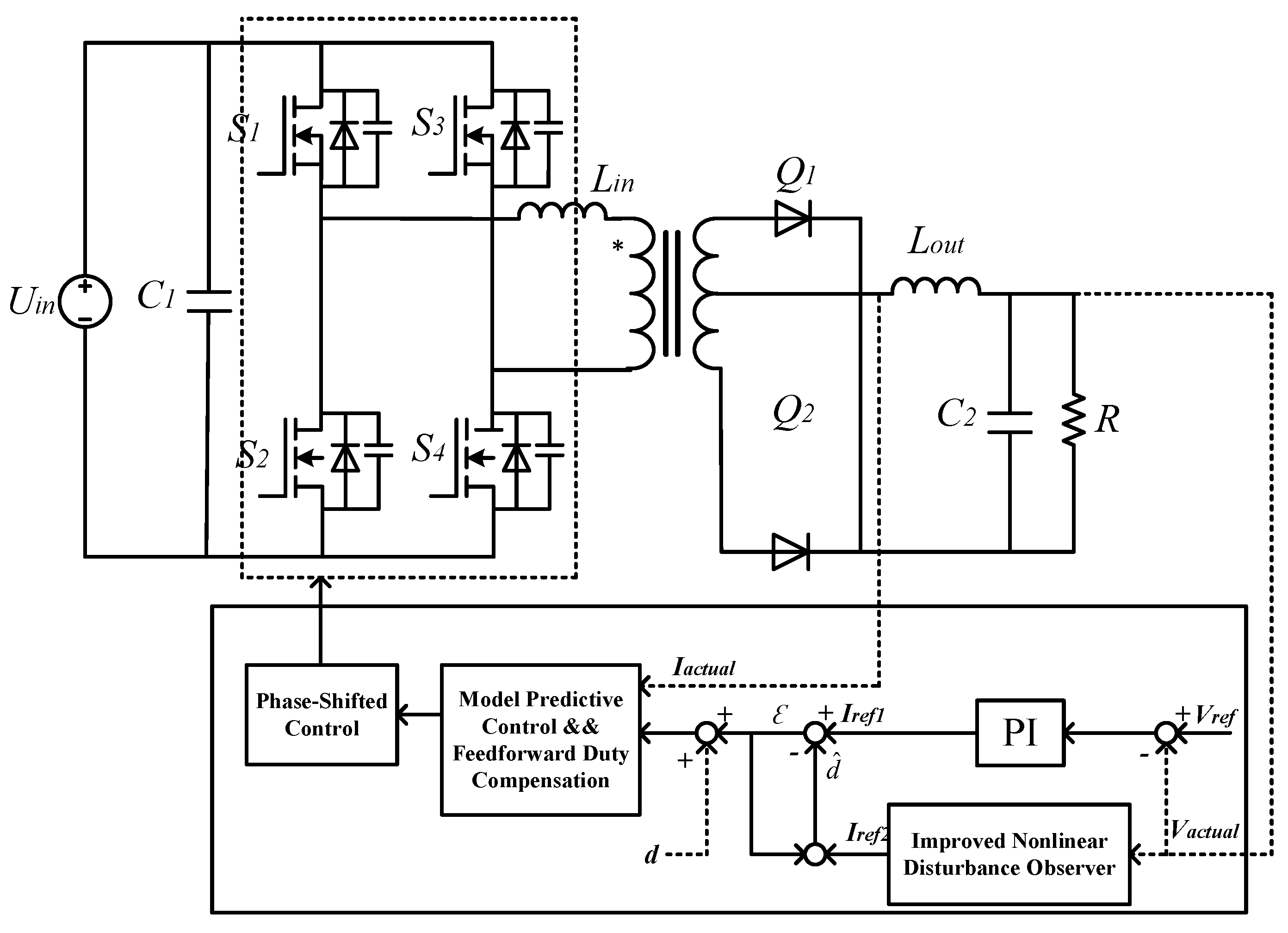
To improve the power output performance of high-power electrolytic plating equipment and enhance the dynamic response and disturbance resistance of the DC-DC converter, the core component of electrolytic plating, a phase shifted full bridge converter predictive control strategy based on an improved nonlinear disturbance observer is proposed. Firstly, a controller inner loop structure based on model predictive control algorithm is constructed to enhance the dynamic response capability of the current inner loop; Secondly, design an improved nonlinear disturbance observer to estimate the changes in electronic component parameters and external disturbances of the converter; Finally, design a feedforward compensation loop to improve the inherent duty cycle loss problem of phase-shifting full bridge converters. The simulation results show that the proposed control strategy can effectively improve the dynamic performance and anti-interference ability of the system.
Keywords:
1. Introduction
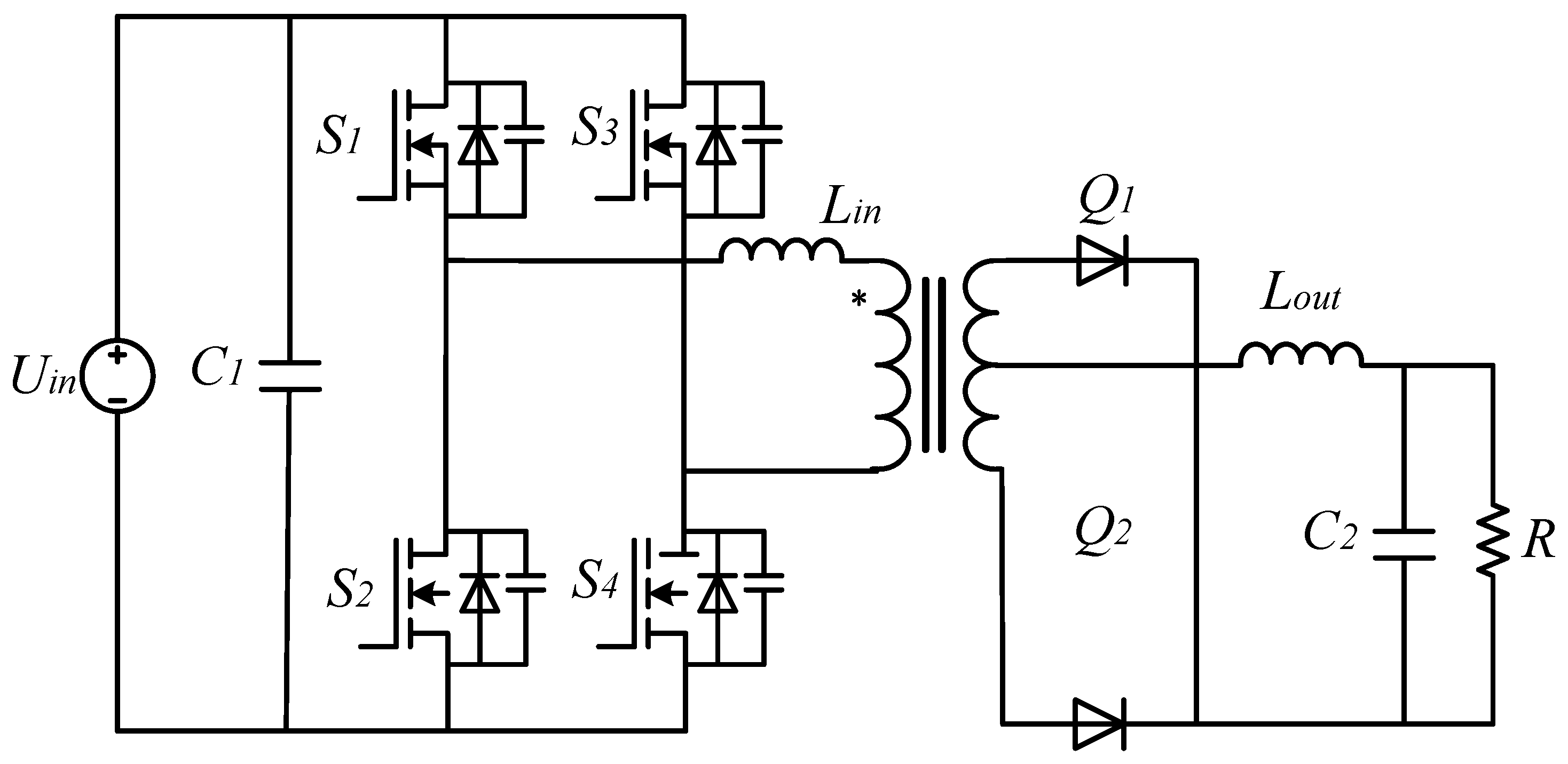
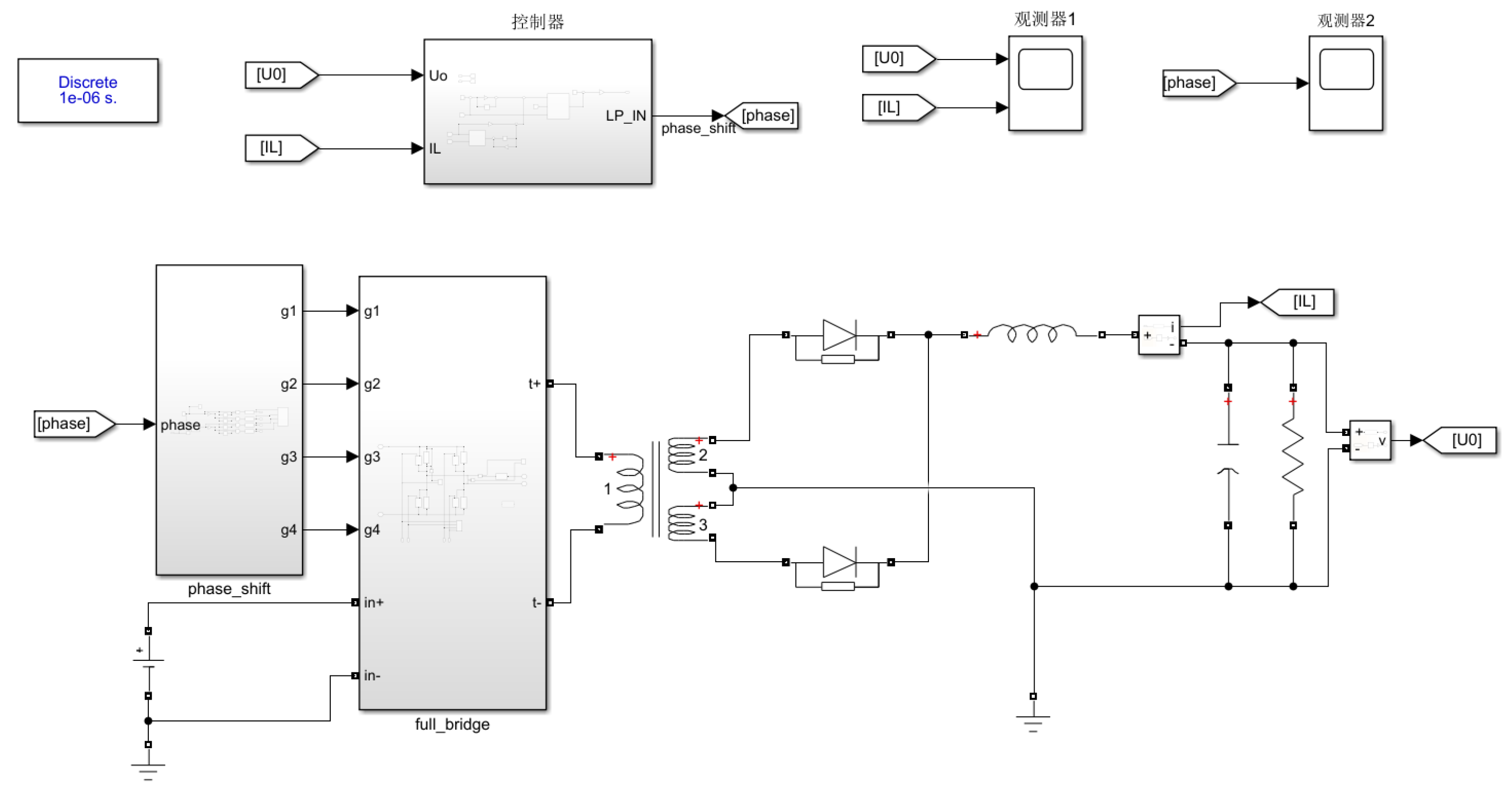
2. PSFB Converter Modeling
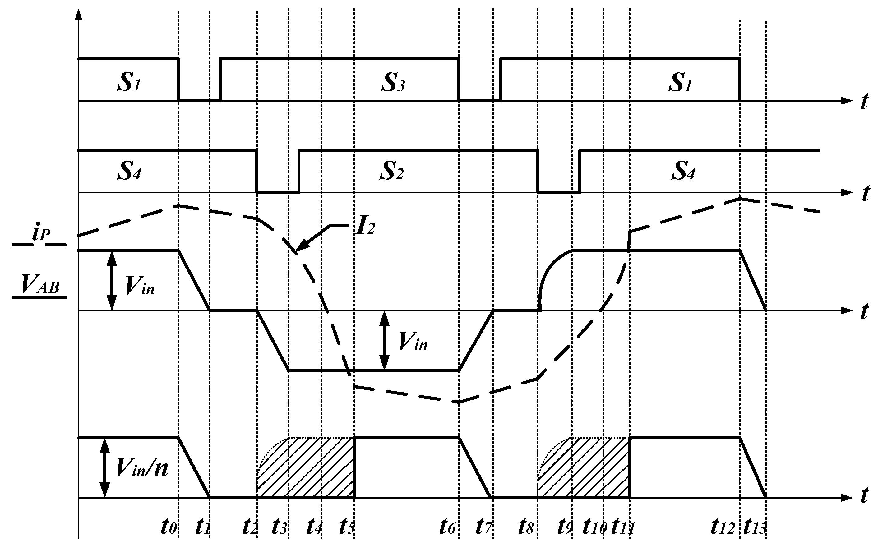
2.1. PSFB Working Principle
2.2. Equivalent Mathematical Model
2.3. Control Framework Design
3. PSFB Controller Design
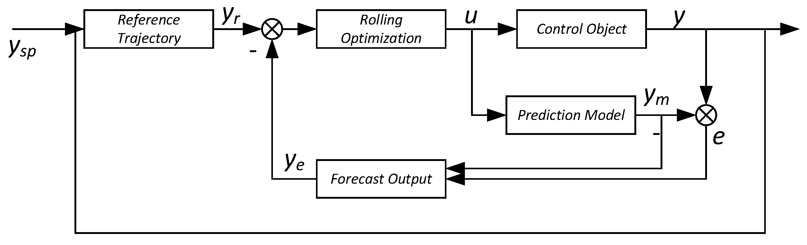
3.1. Model Predictive Control Strategy
3.2. Disturbance Observer Design
3.3. Duty Cycle Compensation and Phase Shift Control
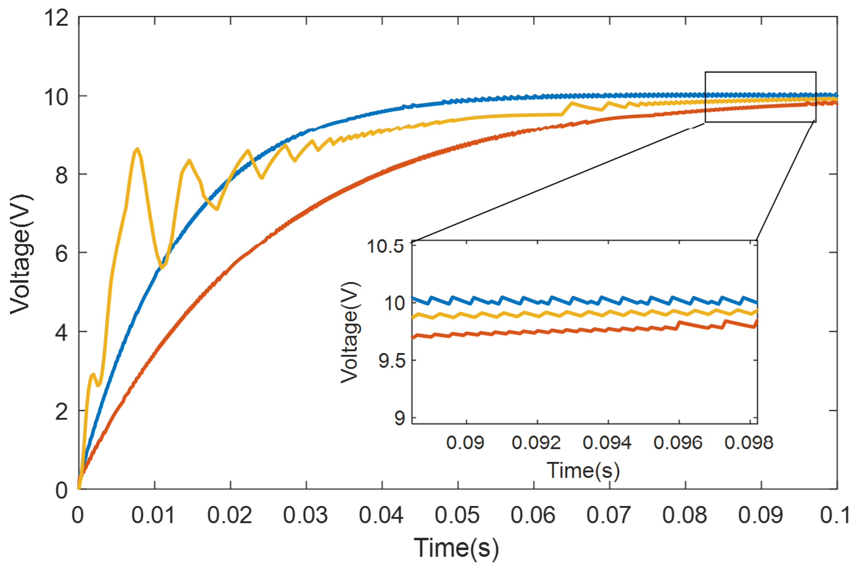
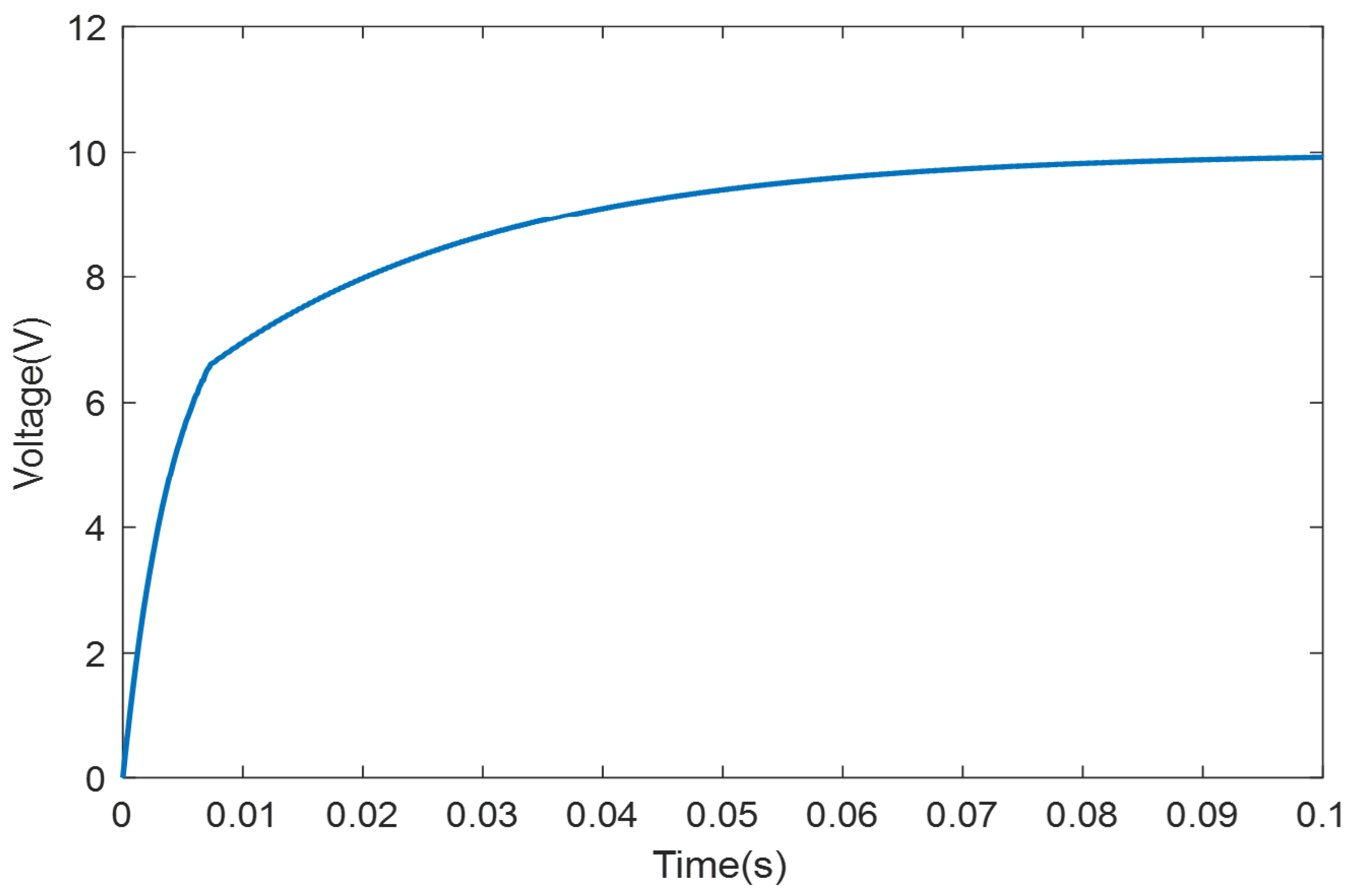
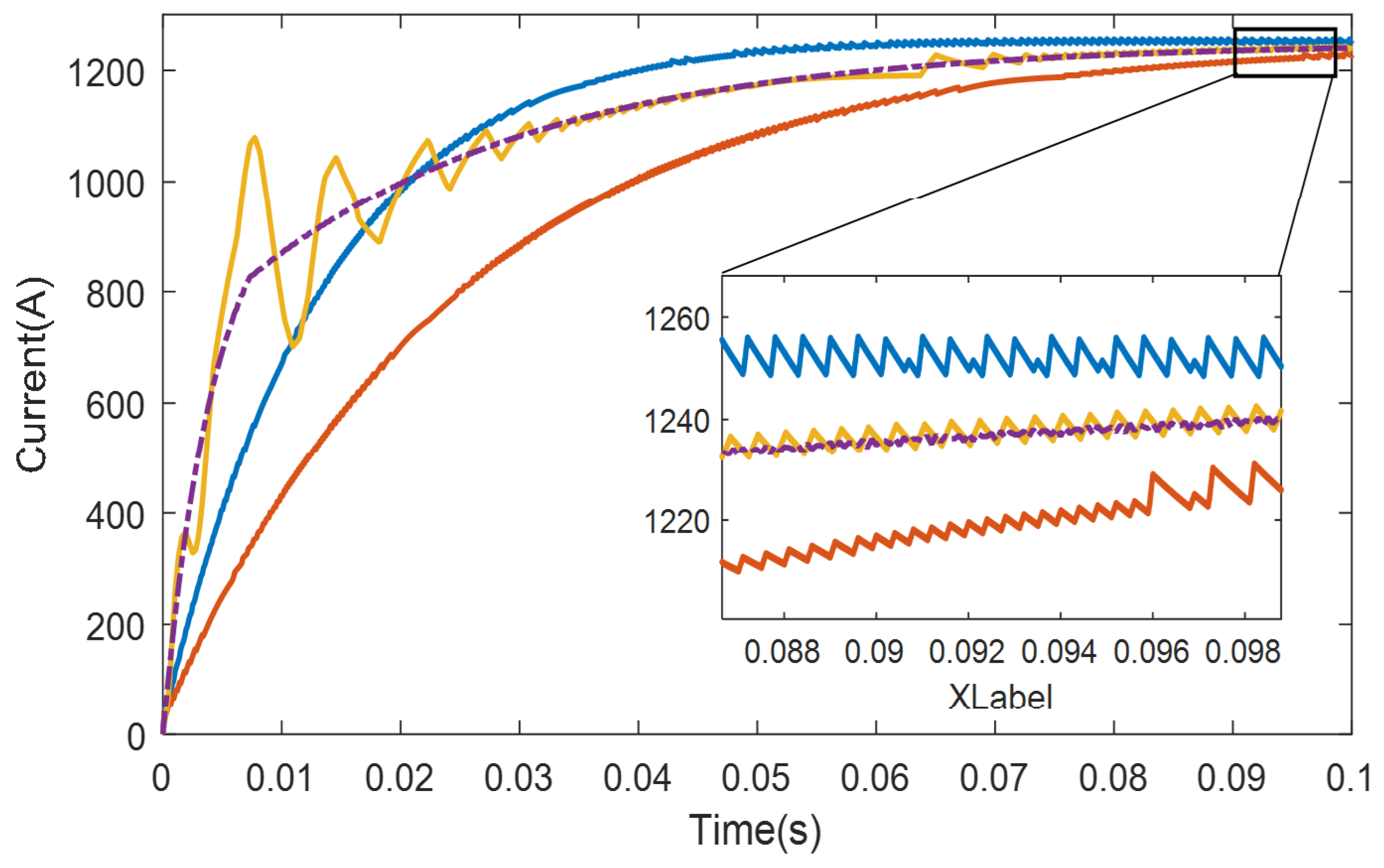
4. Simulation Verification
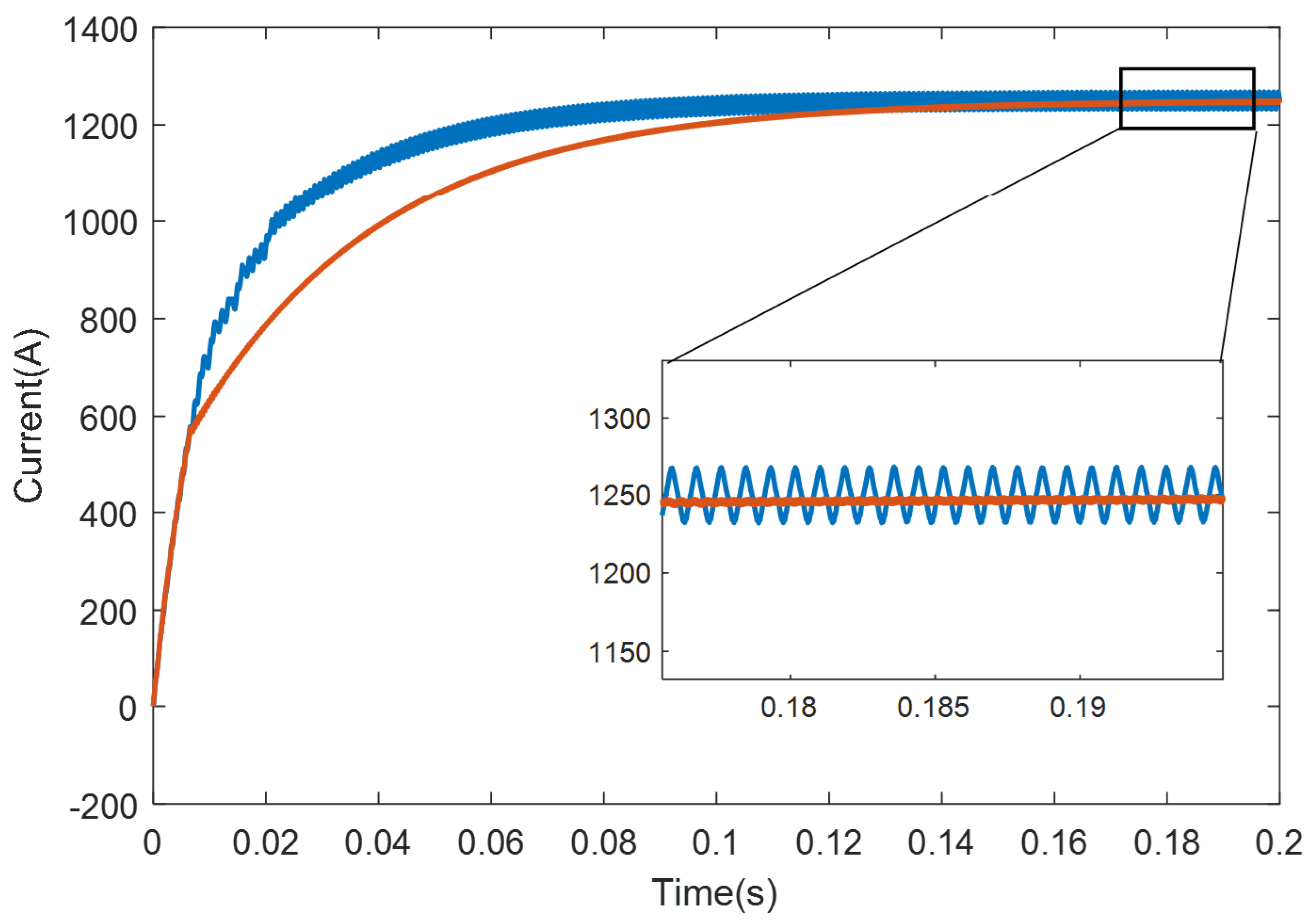
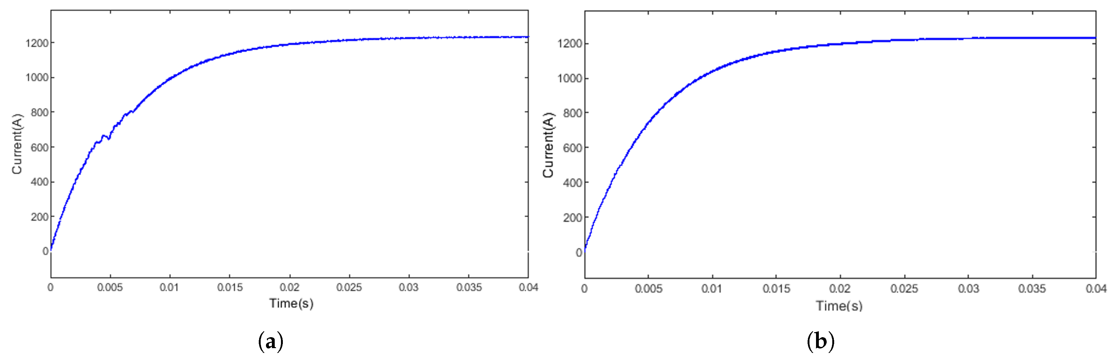
4.1. Comparison Experiment of Traditional PI Control
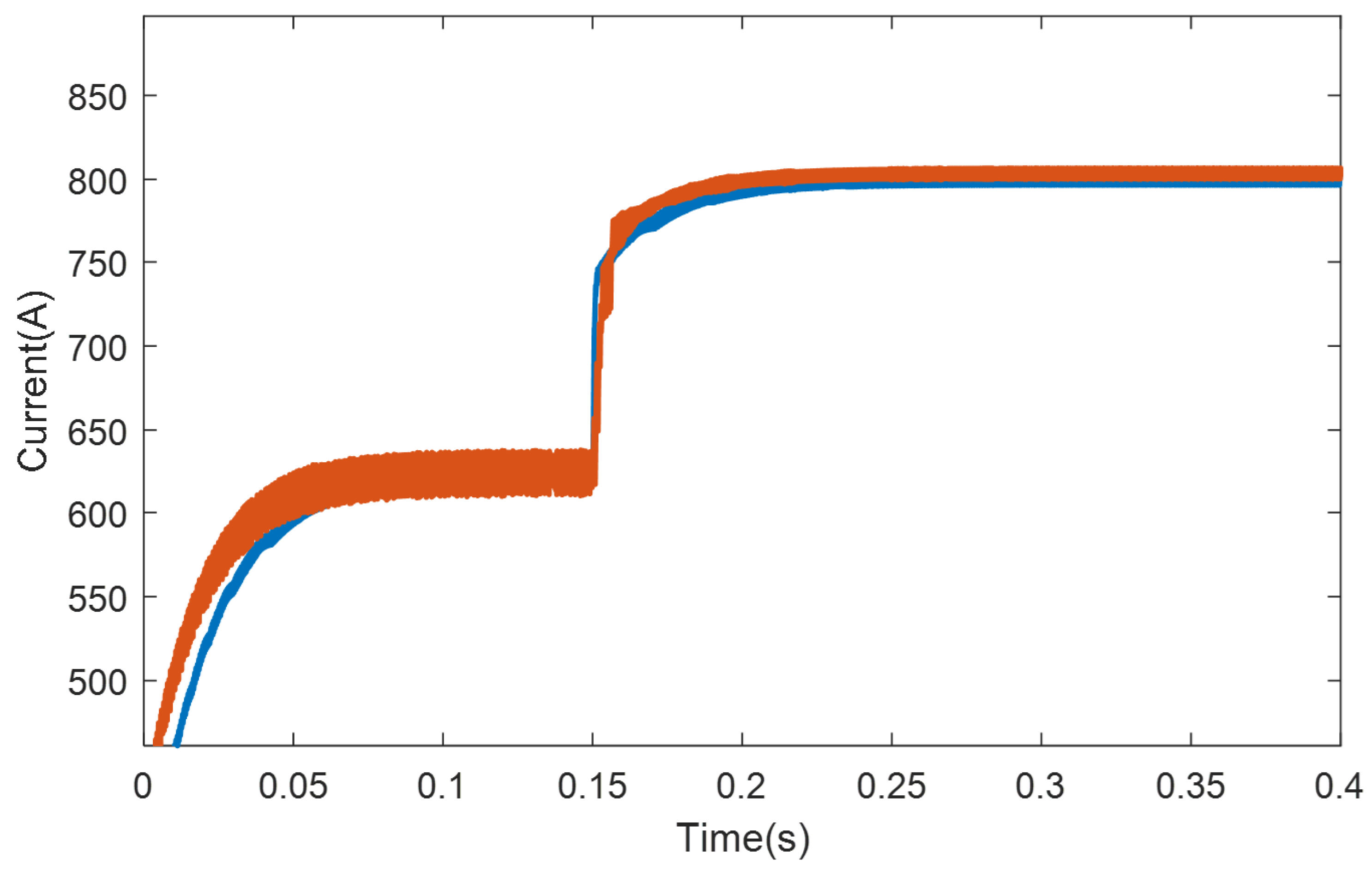
4.2. Load Mutation Experiment
4.3. Inductance Parameter Mismatch Experiment
4.4. Current Random Disturbance Experiment
5. Conclusions
References
- Xu, Z.; Pan, J. Research review of phase-shifted full-bridge ZVS DC converters. Journal of Power Sources 2022, 20, 11–27. [Google Scholar]
- Wang, P.; Xu, Z.; Wang, L.; et al. Hybrid Optimal Control Strategy for Efficiency and Dynamic Performance of Dual Active Bridge DC-DC Converter Based on Triple Phase Shift. Transactions of China Electrotechnical Society 2019, 37, 4720–4731. [Google Scholar]
- Wang, H.; Liu, Z.; Lv, J. Research on Model Predictive Control of Interleaved Parallel Bidirectional DC-DC Converter. Guangxi Electric Power 2022, 45, 49–54. [Google Scholar]
- Liang, M. Dynamic Compensation Control of Buck-type Bidirectional DC-DC Converter Based on Model Predictive Control. Journal of Power Supply 2024, 22, 90–97. [Google Scholar]
- Dang, C.; Wang, F.; Mu, X.; et al. Double Vector Predictive Constant Frequency Control of Vienna Rectifier with Inductance Parameter Identification. Proceedings of the CSEE 2022, 42, 246–255. [Google Scholar]
- Feng, X.; Cui, X.; Shao, K.; et al. A Linear Active Disturbance Rejection Control Strategy for Vienna Rectifier. Power Electronics Technology 2020, 54, 103–105. [Google Scholar]
- Fu, X.; Wang, L.; Wang, X.; et al. Nonlinear Sliding Mode Control Strategy for Grid-Connected Photovoltaic Inverters. Journal of Shenyang University of Technology 2022, 44, 694–699. [Google Scholar]
- Zhang, W.; Chen, L. Model Predictive Control Strategy for Three-phase Inverter Based on Disturbance Suppression. Electric Drive 2019, 51, 43–50. [Google Scholar]
- Xu, H. Research on High-reliability and High-Power Electroplating Power Supply. PhD thesis, Zhengzhou University, 2015. [Google Scholar]
- Di Capua, G.; Shirsavar, S.A.; Hallworth, M.A.; Femia, N. An Enhanced Model for Small-Signal Analysis of the Phase-Shifted Full-Bridge Converter. IEEE Transactions on Power Electronics 2015, 30, 1567–1576. [Google Scholar] [CrossRef]
- Sun, T. Model Prediction of Direct Velocity Weak Field Control Strategy for Permanent Magnet Synchronous Motor Parameter Identification. PhD thesis, Xi’an University of Technology, 2023. [Google Scholar]
- Liu, X.; Li, K.; Zhang, Q.; Zhang, C. Single-loop Predictive Control of PMSM Based on Nonlinear Disturbance Observers. Zhongguo Dianji Gongcheng Xuebao/Proceedings of the Chinese Society of Electrical Engineering 2018, 38, 2153–2162. [Google Scholar]
- Liu, Z.; Yuan, S.; Zheng, L.; Ma, Y.; Sun, Y. An improved NMPC-NDOB scheme for trajectory tracking of unmanned surface vessel. Proceedings of the Institution of Mechanical Engineers, Part M: Journal of Engineering for the Maritime Environment 2022, 236, 1012–1024. [Google Scholar] [CrossRef]
- Cao, L.; Li, Y.; Li, X.; Guo, L.; Jin, N.; Cao, H. A Dual-Vector Modulated Model Predictive Control Method for Voltage Source Inverters with a New Duty Cycle Calculation Method. Energies 2020, 13. [Google Scholar] [CrossRef]

| Parameter | Value |
|---|---|
| Input Voltage Uin/V | 800 |
| Input Filter Capacitor C/uF | 250 |
| Output filtering inductance L/mH | 1 |
| Output filter capacitor C/uF | 600 |
| Rated output voltage Uout/V | 10 |
| Output current Iout/A | 1250 |
| Switching frequency f/KHz | 10 |
Disclaimer/Publisher’s Note: The statements, opinions and data contained in all publications are solely those of the individual author(s) and contributor(s) and not of MDPI and/or the editor(s). MDPI and/or the editor(s) disclaim responsibility for any injury to people or property resulting from any ideas, methods, instructions or products referred to in the content. |
© 2025 by the authors. Licensee MDPI, Basel, Switzerland. This article is an open access article distributed under the terms and conditions of the Creative Commons Attribution (CC BY) license (http://creativecommons.org/licenses/by/4.0/).


