1. Introduction
The components with specular surfaces are widely used in aerospace, optics systems, etc. There is a large number of components consisting of separated specular surfaces not just a continuous specular surface to efficiently adjust optical paths and reduce the volume of optical instruments, such as monolithic multi-surface workpieces (MMSWs) in imaging spectrometers and off-axis telescopes [
1,
2,
3,
4]. As an effective contact measurement method, a coordinate measurement machine (CMM) can measure specular surfaces accurately but with injury to the specular surfaces [
5]. As an effective non-contact measurement method, interferometry can only measure sample and small-scale specular surfaces [
6]. Effective measurement technologies for the components with separated specular surfaces are urgently needed. Reaching high efficiency and accuracy, phase measuring deflectometry (PMD) is a no-contact, full-field measurement technology for specular surfaces. A system of PMD usually consists of cameras and monitors. Reflected and distorted by the specular surfaces under test (SUT), the patterns displayed by the monitors are recorded by the cameras. In a calibrated PMD system where the position and posture among the cameras and monitors is solved, from the captured distorted patterns, the three-dimensional (3-D) reconstruction of SUT can be conducted [
7]. PMD completes 3-D reconstruction with high accuracy and simple equipment, which is very competitive in the field of measuring specular surfaces [
8].
At present, PMD mainly focuses on the 3-D reconstruction of continuous SUT, achieving great success. With reprojection error on the monitor as a cost function, Ref. [
9,
10] models SUT to convert the reconstruction to the optimization of the parameters of the model. Ref. [
11,
12] measures slope distribution of SUT by binocular cameras; The reconstruction is conducted by integration of the slopes. In a PMD system of one camera, Ref. [
13] reconstructs a continuous SUT through the differential geometry analysis of the surface. Recently, Ref. [
14] measures the slope distribution of a continuous SUT with telecentric imaging lens and Fourier lens which makes distortion of reflected patterns only sensitive to the slopes. Solving the problem of the height-slope ambiguity [
15], the development of PMD in measuring continuous SUT makes it a more and more mature technology.
When it comes to the reconstruction of separated or discontinuous specular surfaces, previous PMD schemes need a translating monitor [
16,
17] or more than one monitor [
18,
19,
20]. However, the extra or translating monitors are prone to enlarge the error in the reconstruction and make the measurement difficult. Thus, PMD with fixed hardware is urgently demanded for accurate and simple measurement of separated specular surfaces. With the fixed hardware of stereoscopic PMD (stereo-PMD), Ref. [
21] models discontinuous specular surfaces with a B-spline surface; According to the slope distribution solved by stereo-PMD, it solves control points of the B-spline surface to reconstruct SUT, improving the accuracy of reconstruction and solving the 3-D coordinate of SUT in the camera coordinate system rather than merely the relative height of the reflecting points [
22,
23].
With the hardware of stereo-PMD and the coordinate of a reflecting point solved by stereo-PMD in advance, Ref. [
24] introduces a mechanism of iterative reconstruction of a continuous SUT. Because it only solves the coordinate of a single reflecting point, the method based on the mechanism is more efficient than stereo-PMD which solves the slope distribution of all the reflecting points point by point and is followed by the integration of the slopes. However, the accuracy of the method completely depends on the single reflecting point whose accuracy can be ensured hardly in actual measurement. The application of the mechanism in PMD should be further researched to resist the noise of the single point and extend to the separated SUT.
In this paper, a deflectometric iterative reconstruction method is proposed to increase the noise robustness of the mechanism and to extend the mechanism to the measurement of separated SUT. With the SUT modeled by the B-spline surface, the mechanism is analyzed mathematically, verifying that the single reflecting point can be replaced with the sparse point cloud of SUT to increase the robustness of the methods. With the modeled SUT, the B-spline surface makes it possible to iteratively reconstruct separated SUT based on the mechanism. In the iteration process, the x, y components of the coordinate of reflecting points in the camera coordinate system are variant, different from the fixed x, y components calculated by stereo-PMD in Ref. [
21]. Thus, according to the updated slopes, a new method of reconstructing the SUT in the form of the B-spline surface in every iteration process is proposed.
2. Proposed Methodology
In this section, the mechanism of the proposed method is introduced in detail, firstly. Secondly, stereo-PMD is employed to solve the 3-D coordinate of a reflecting point. Finally, combined with the model of the perspective projection camera, a B-spline surface is introduced to model SUT. Meanwhile, the mathematical analysis of the mechanism is conducted to replace the single reflecting point with the sparse point cloud of SUT.
2.1. Mechanism of the Proposed Method
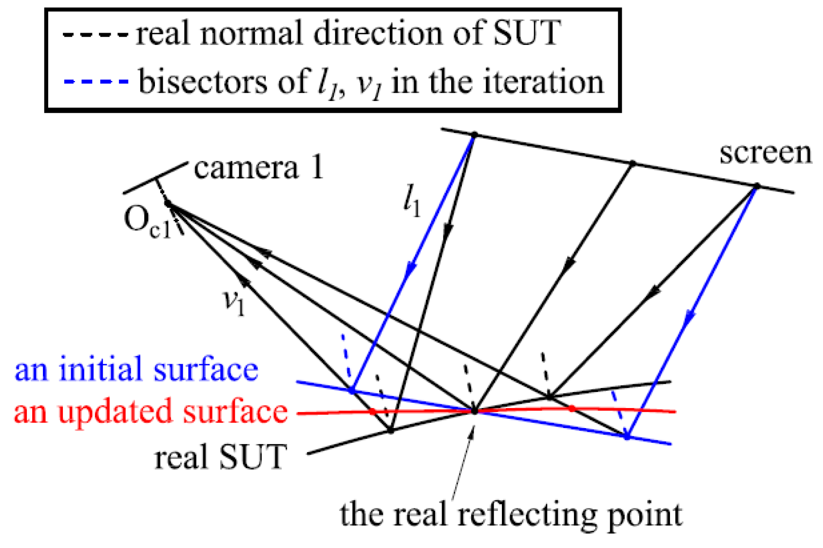
As an initial surface passes through a real reflection point, the updated gradient set, calculated with the bisector of
l1 and
v1, is different from the gradient set of the initial surface and more approximated to the real gradient set of SUT, illustrated in
Figure 1. Passing through the real reflection point, the updated surface reconstructed according to the updated gradient set is also closer to SUT. With the updated surface as a new initial surface, the newly updated surface will be much closer to SUT than the previously updated surface. Thus, as the iteration progresses, the iteratively updated surface will be an approximation of SUT. In the reconstruction of every iteration process, a B-spline surface is employed to fit the surface according to the updated gradient set. The process of the iteration is listed as follows: Firstly, an initial B-spline surface through the point is fitted to calculate an updated gradient set; Secondly, according to the updated gradient set, a new B-spline surface through the points is updated. Finally, the B-spline surface is updated iteratively according to the first and second steps, until the variation of the 3-D coordinate between two surfaces in the two adjacent iteration processes is less than a preset variation threshold. When the iteration process terminates, the B-spline surface is the reconstruction of SUT. The 3-D coordinate of the real reflecting point is solved by stereo-PMD; The reconstruction at each iteration process is based on the perspective projection camera model and the differentiation properties of the B-spline surface.
2.2. Stereo-PMD for a Reflecting Point
The proposed method employs stereo-PMD to calculate the coordinate of a reflection point on every separated surface of SUT which the updated surfaces pass through. In the measurement of SUT, two cameras record reflected fringe patterns of SUT which are displayed by the monitor and selected by the technique of fringe pattern analysis [
25,
26].
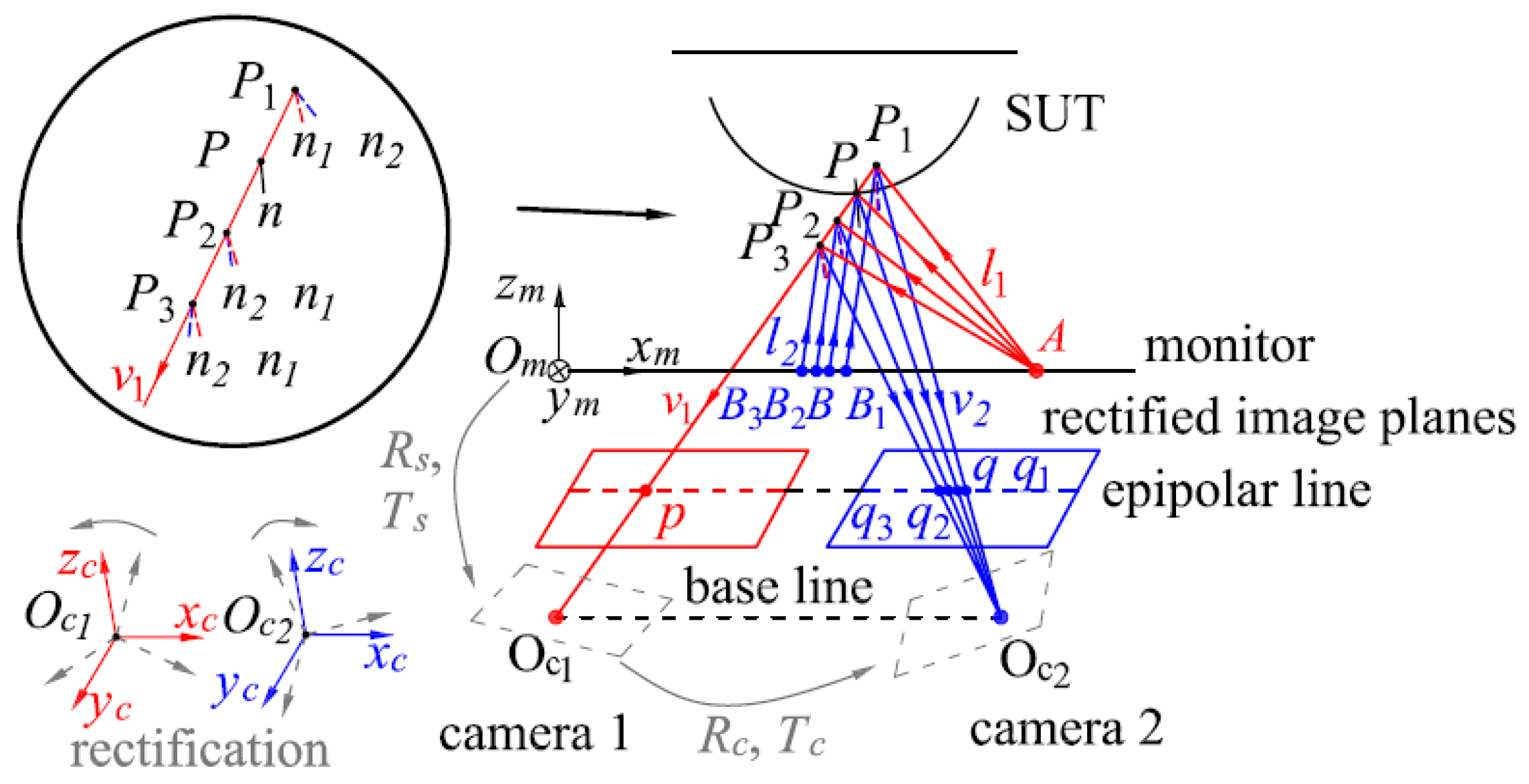
After calibration of the stereo-PMD system, the intrinsic matrixes
Ki (
i=1, 2) of the cameras, the rotation matrix
Rc and translating vector
Tc between the camera coordinate systems (
Oc-
xc-
yc-
zc),
Rm and
Tm between camera 1 and the monitor coordinate system (
Om-
xm-
ym-
zm) are obtained, illustrated in
Figure 2. According to
Rc and
Tc, images of the cameras are rectified [
27] to make the epipolar lines and rows of pixels colinear. According to
Rm and
Tm, the pixel coordinate on the monitor is transformed into the coordinate system of camera 1. With the unwrapped phase [
25,
26], the correspondence between the pixels of the cameras and the monitor can be established, such as
p and
A,
q and
B in
Figure 2. Based on the law of reflection, the bisectors
ni (
i=1, 2) of the incident and emergent lights
li,
vi should be coincident at the reflection point
P, which is the normal direction
n of SUT at
P. It is the criterion to match the base integer pixel
p with its homologous pixel
q. Along the epipolar line (the same row of
p in camera 2), sub-pixel coordinate
q, which corresponds to the largest consistency of the bisectors among
q and
qj (j=1, 2, 3) in
Figure 2., is the sub-pixel homologous pixel of
p, illustrated in
Figure 2. The iterative matching method in [
11] can be applied to match
q and
p. With
q and
p, the coordinate of
P(
xc,
yc,
zc) can be calculated by triangulation.
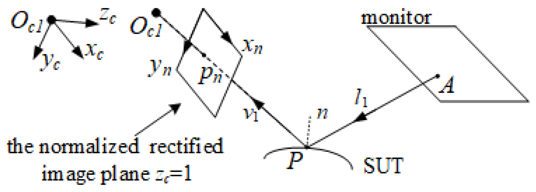
2.3. Perspective Projection Model
In the perspective camera model in
Figure 3, for every pixel
p in camera 1,
pn=
K1-1[
p 1]
T= [
xn yn 1]
T is the coordinate of
p on the normalized image plane. The coordinate of the reflection point
P can also be expressed as
s(
xn,
yn)
pn, where
s(
xn,
yn) is equal to the
z component of
P (the depth of
P). Thus, the reconstruction of the updated surfaces is equivalent to solving the value
s of
p. The relationship between the gradient set
and the slope set
which respectively describe the slopes of the point
P in the camera coordinate system and the slope of
s on the normalized image plane, can be expressed as [
21]:
2.4. B-Spline Surface
In the proposed iterative method, s(xn, yn) are modeled by a B-spline surface in the form of S= WC, where S is a column vector with every element corresponding to the depth s of every reflection point, C the column vector of the control points of the B-spline surface, W a parameters matrix with the elements of every row corresponding to the values of the B-spline basis functions at (xn, yn). For the kth element S(k) of S, the coordinate of P in the camera coordinate system is S(k) pn(xn, yn, 1). The task of reconstruction at each iteration process is to solve C according to the updated gradient set.
Partial derivatives of
s(
xn,
yn), denoted as
and
, in the form of B-spline surfaces are B-spline surfaces with the basis functions one order lower than
s(
xn,
yn) in the directions of
xn and
yn, respectively. The column vectors of the control points of
and
are denoted as
Cx, and
Cy, respectively. For the B-spline surfaces, the parameters matrices
Dx,
Dy describe the inherent relationship between
C and
Cx,
Cy, respectively. Thus,
,
can be expressed as
where
Wx,
Wy respectively denote the parameters matrices of the surfaces. Substituting Equation (2) into Equation (1),
is derived in the form of
AC=0, where
Xn, and
Yn respectively denote column vectors of
xn and
yn; ‘.*’ denotes Hadamard product. Because the rank of
A minus its number of columns is -1 [
21], the explicit solution of
C should be scaled to
C·
sk_real/
S(
k), where
sk_real is a pre-known depth of
S(
k) calculated by previous stereo-PMD.
In
Section 2.1, the mechanism is introduced with the one real reflecting point. The conclusion of the rank of
A makes it rational to scale
C with more than one reflecting point, such as the sparse point cloud of SUT, resulting in higher noise robustness. The sparse point cloud scales
C to
where
K is the number of points in the cloud and
sk is the calculated depth of the
kth point in the cloud by stereo-PMD.
If SUT with
n separated specular surfaces is measured,
S=
WC will be in the form of (
S1, …,
Sn)’= (
W1, …,
Wn)’*(
C1, …,
Cn)’ which distinguishes separated surfaces automatically for the local definition of the B-spline surfaces. The method of constructing
W of discontinuous surface refers to Ref. [
21].
n points with known depth respectively on the surfaces or the sparse point cloud of the
n separated surface can be used to scale
C1, …,
Cn, respectively.
3. Experiments
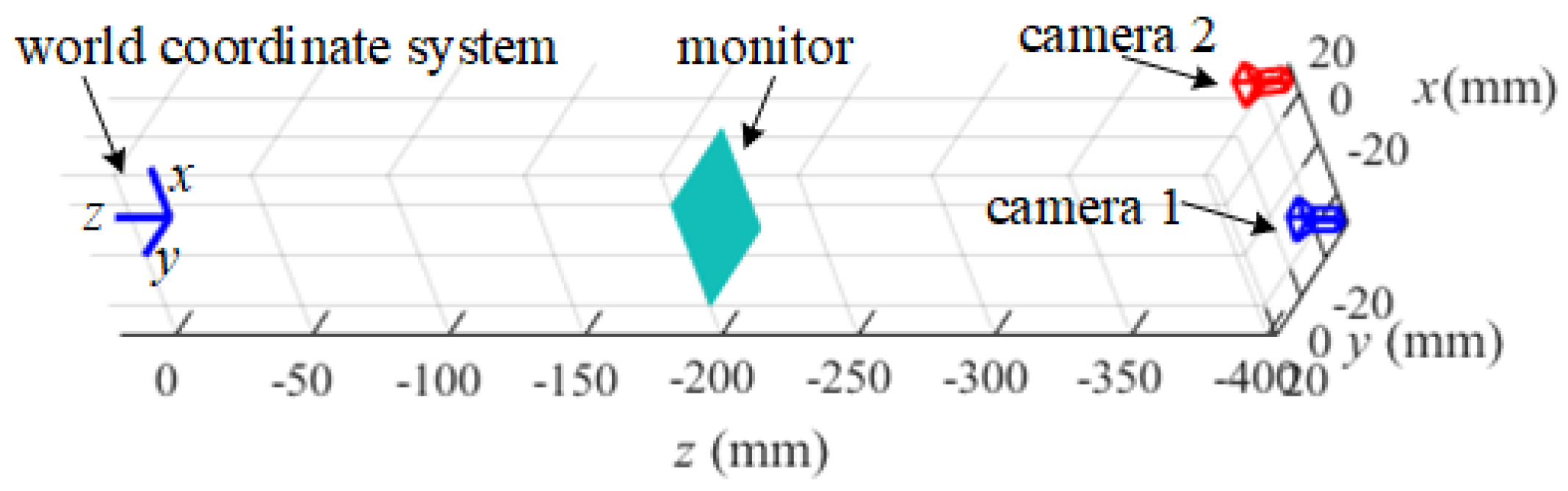
3.1. Simulation
For testing the proposed reconstruction method, a simulated system of stereo-PMD is set up to conduct experiments, illustrated in
Figure 4. In the simulation, the SUT of a cylinder with a radius of 100 mm and the SUT with four separated parallel specular planes with a distance of 5 mm are measured separately.
Figure 5. (a) and
Figure 6. (a) illustrate the SUTs in the world coordinate system, respectively. The corresponding relationship between the pixels of the cameras and the monitor is established by the spatial geometric relationship between the cameras and the monitor. With an adjacent knot interval of 5 pixels, the B-spline surfaces of cubic basis functions are used to model the SUT. The stereo-PMD solves the coordinate of a real reflecting point and the sparse point cloud of SUT. The proposed iterative reconstruction method is conducted in the coordinate system of camera 1.
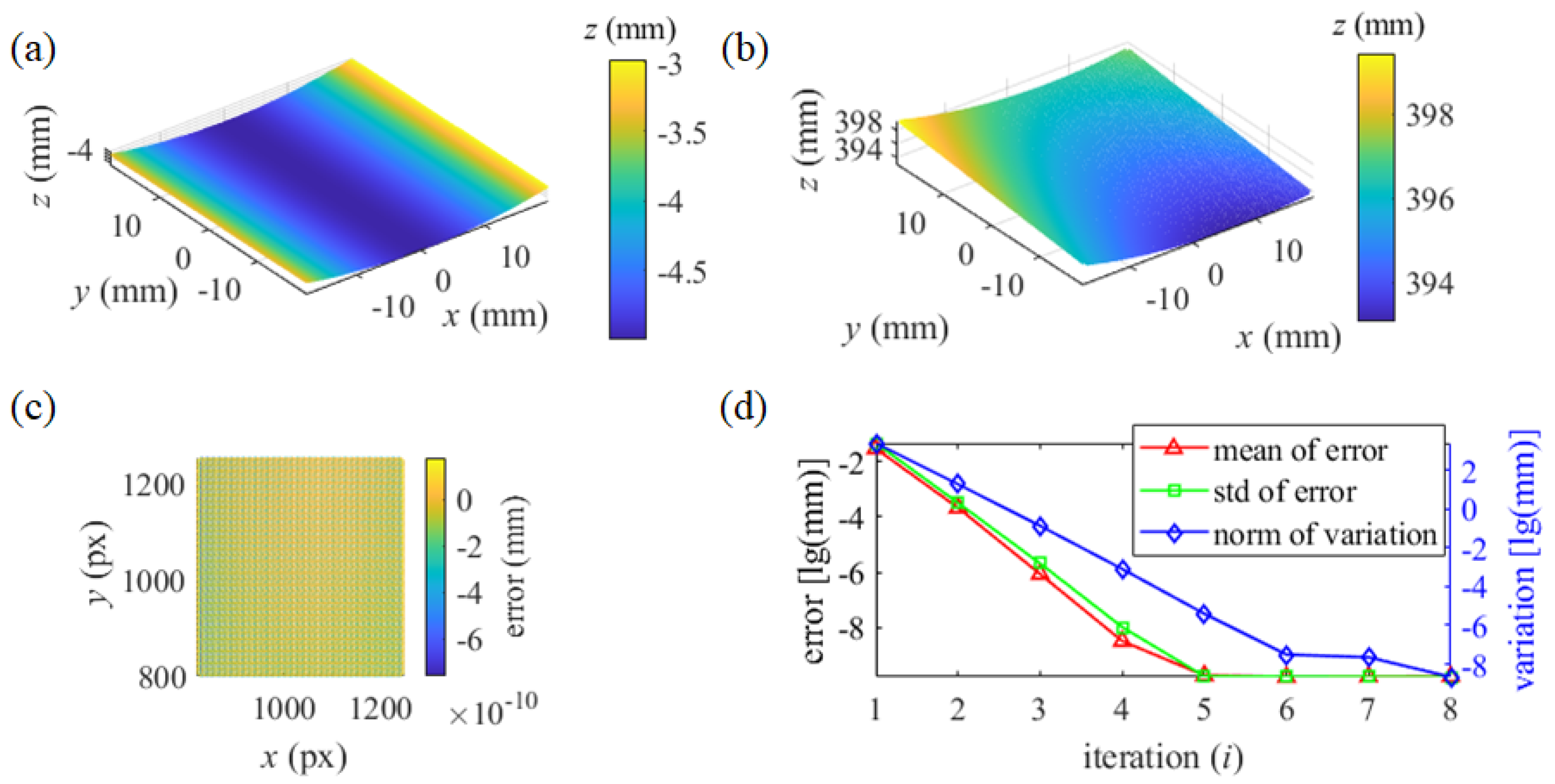
In testing the proposed iterative method, with the initialization as a plane, the updated B-spline surface passes through the reflecting points with their real coordinates. The reconstruction of the cylinder in the coordinate system of camera 1 is illustrated in
Figure 5. (b). With every pixel of camera 1 corresponding to the depth of a reflecting point, the error of depth is illustrated in
Figure 5. (c). The mean value and standard deviation (std) of the depth error in every iteration process and the norm of the depth variation of every updated surface are illustrated in
Figure 5. (d).
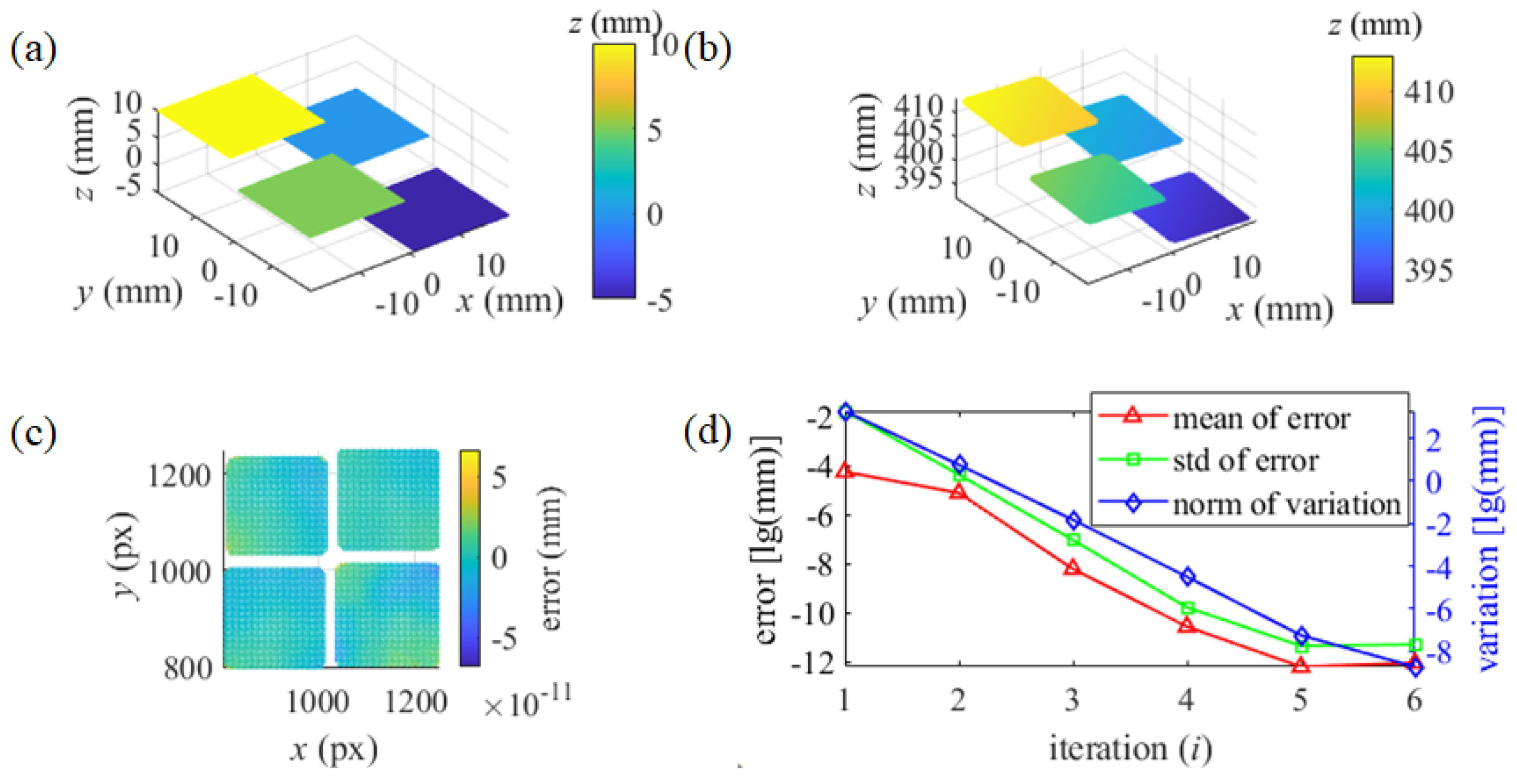
In measuring the separated SUT, four reflecting points with the real coordinates respectively on the planes are used to scale
C1, …, and
C4, respectively. The reconstruction of SUT, error of the depth, and the process of iteration are illustrated in
Figure 6. (b)-(d), respectively. The accuracy of the iterative reconstruction method and its mechanism can be verified by the simulation.
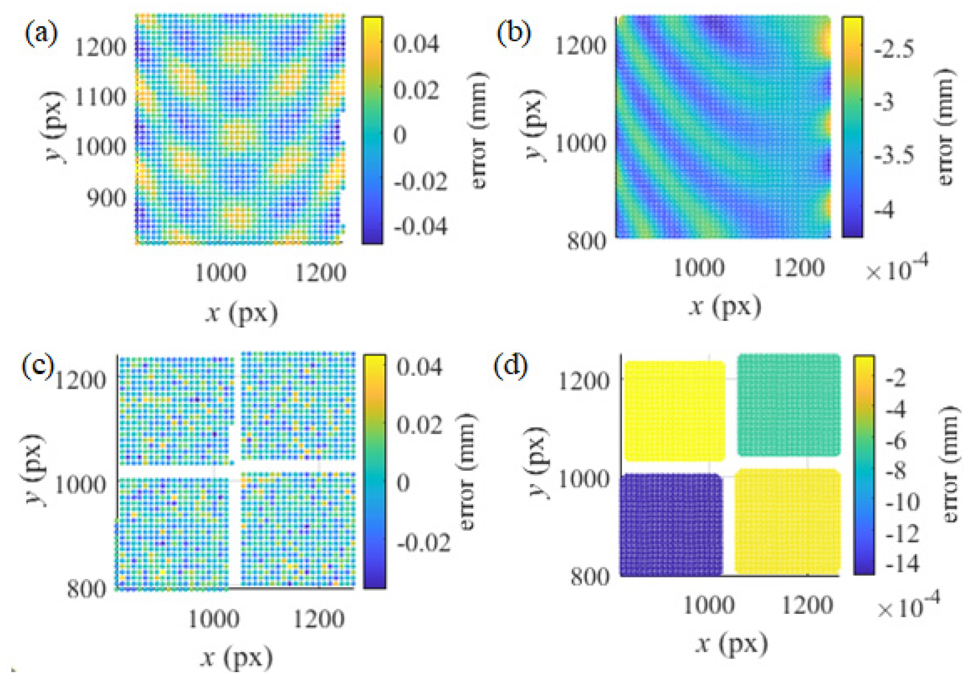
However, disturbed by noise, the real coordinates of the reflection points can be obtained hardly in actual measurement. To verify the noise robustness of the method, the intensity noise of uniform distribution
U(-5, 5) is added to the ideal fringe patterns which are generated by the spatial geometric relationship. The proposed iterative reconstruction method is conducted. With the noisy patterns, the simulated stereo-PMD is employed to obtain the sparse point cloud of SUTs with the base pixels interval of 10 pixels (px); With the noisy patterns, the control points of the B-spline surfaces in every iteration process are scaled by the point cloud according to Equation 4. The depth error distribution of the point cloud by the stereo-PMD is illustrated in
Figure 7. (a) and (c); The depth error of the reconstruction by the proposed method is in
Figure 7. (b) and (d) which verify the robustness of the method.
3.2. Actual Measurement
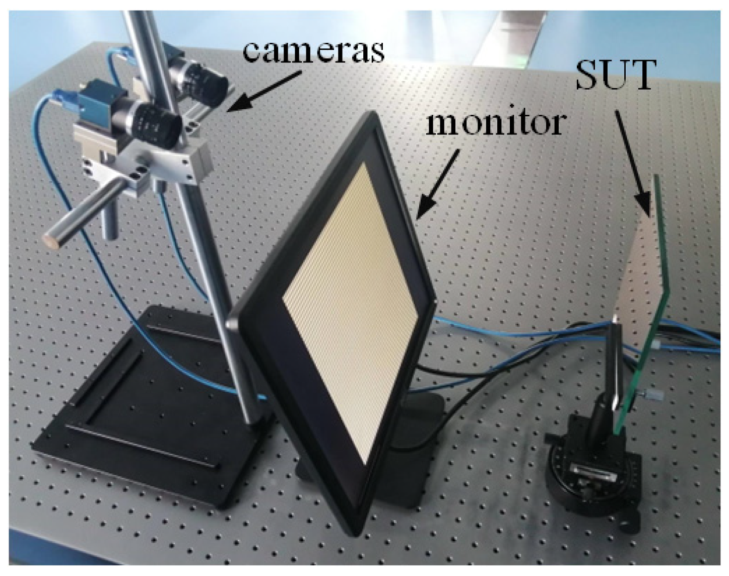
To verify the proposed method in actual measurement, a system of stereo-PMD was set up with two cameras (DAHENG IMAGING, MER2-503-36U3M) and a computer monitor (DELL E1715S), illustrated in
Figure 8. With the assistance of a plane mirror, the system was calibrated with the calibration methods in [
11,
17] to obtain
Ki (
i=1, 2),
Rc,
Tc,
Rm, and
Tm.
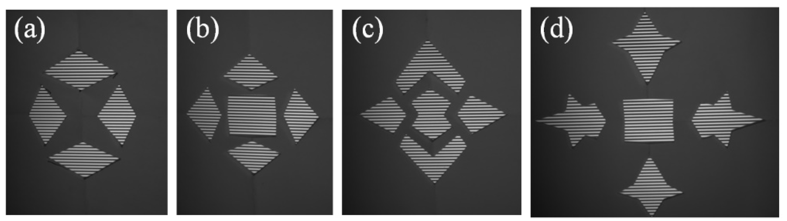
In the measurement, the monitor displayed fringe patterns in horizontal and vertical directions, separately. The reflected patterns by SUTs were recorded by the cameras. In the measurement, four SUTs were measured, separately.
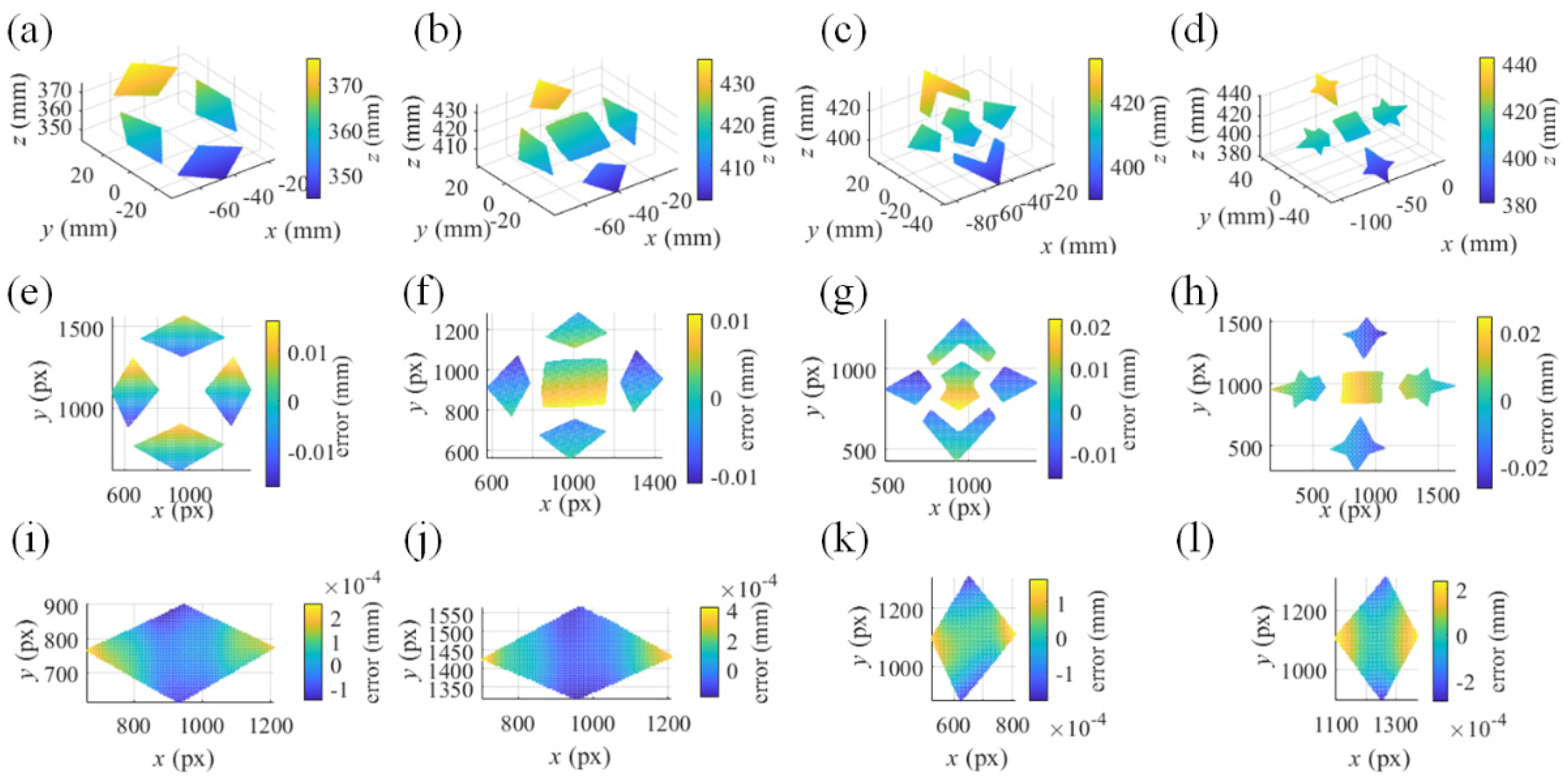
Figure 9. illustrates the reflected fringe patterns of horizontal direction recorded by camera 1. With the unwrapped phase maps, the stereo-PMD solved the sparse point cloud of the SUTs. The plane mirror at one of the poses in the calibration was treated as an initial surface. Scaled by the point cloud, the proposed method iteratively reconstructed the SUTs, illustrated in
Figure 10. (a)-(d). Measured by an interferometer, the separated surfaces of the measured SUTs are coplanar with a residual error of less than one micrometer. Illustrated in
Figure 10. (e)-(h), the reconstruction of SUTs was respectively fitted by planes with root mean square error (rmse) 0.0066 mm, 0.0057 mm, 0.0093 mm, and 0.0146 mm, which was more accurate than the sparse point cloud with the rmse 0.0193 mm, 0.0407 mm, 0.0281 mm and 0.0370 mm. With the reconstruction of every single separated surface of the SUT in
Figure 9. (a) separately fitted by a plane,
Figure 10. (i)- (l) illustrate the residual depth error distribution of the fitting. For all the SUTs, the rmse of the separate fitting remains at the level of 1e-5~ 1e-4 mm. For all the SUTs, the angles among the normal directions of the planes of the separate fitting were with mean value 0.0043° and std 0.0026°, which were more accurate than the sparse point cloud with mean value 0.0958° and std 0.0685°.
The system of PMD can reach higher precision in measuring the similar specular surface in Ref. [
17] with the rmse 0.0240mm which measures SUTs with a PMD system of a translating monitor. The proposed method can reconstruct the separated specular surface with accuracy in the 3-D coordinate and the angles of the surfaces successfully. Meanwhile, the accuracy of the reconstruction by the stereo-PMD can be improved by the proposed method.
4. Conclusions
In this paper, an iterative reconstruction method of reconstructing separated specular surfaces is proposed. The method and its mechanism are introduced in detail and verified in the simulated and the actual measurements. Different from the traditional stereoscopic deflectometry which integrally reconstructs surfaces with the fixed x, y components of the coordinate and the slope of every reflection point, the proposed method updates surfaces with the variant x, y components according to the updated slopes. Compared with the point cloud calculated by stereoscopic deflectometry, the proposed method reconstructs surfaces more accurately which is verified in the simulated and the actual measurement. In the future, more effort will be focused on the stability of the method.
Author Contributions
Conceptualization, J.L. and X.A.; methodology, C.L.; software, C.L., H.S., Y.X. and C.Y.; validation, J.L. and X.A.; formal analysis, J.L. and X.A.; investigation, C.L., H.S., Y.X. and C.Y.; resources, C.L. and H.S.; data curation, C.L.; writing—original draft preparation, C.L.; writing—review and editing, J.L. and X.A.; visualization, C.L.; supervision, J.L. and X.A.; project administration, J.L. and X.A.; funding acquisition, J.L. and X.A. All authors have read and agreed to the published version of the manuscript.
Funding
This research was funded by the National Key R&D Program of China (2023YFB3209400), State Key Laboratory of Special Vehicle Design and Manufacturing Integration Technology (GZ2023KF016).
Institutional Review Board Statement
Not applicable.
Informed Consent Statement
The authors declare no conflicts of interest.
Data Availability Statement
Data underlying the results presented in this paper are not publicly available at this time but may be obtained from the authors upon reasonable request.
Conflicts of Interest
The authors declare no conflicts of interest.
References
- Liu, X.W.; Zhou, J.S.; Wei, L.D.; Feng, L.; Jing, J.J.; He, X.Y.; Yang, L.; Li, Y.C. Optical Design of Schwarzschild Imaging Spectrometer with Freeform Surfaces. Opt. Commun. 2021, 480, 126495. [Google Scholar] [CrossRef]
- Meng, Q.Y.; Wang, H.Y.; Wang, K.J.; Wang, Y.; Ji, Z.H.; Wang, D. Off-Axis Three-Mirror Freeform Telescope with a Large Linear Field of View Based on an Integration Mirror. Appl. Opt. 2016, 55(32), 8962–8970. [Google Scholar] [CrossRef] [PubMed]
- Yang, T.; Zhu, J.; Jin, G.F. Compact Freeform Off-Axis Three-Mirror Imaging System Based on the Integration of Primary and Tertiary Mirrors on One Single Surface. Chin. Opt. Lett. 2016, 14(6), 060801. [Google Scholar] [CrossRef]
- Yuan, L.Y.; Xie, J.N.; He, Z.P.; Wang, Y.M.; Wang, J.Y. Optical Design and Evaluation of Airborne Prism-Grating Imaging Spectrometer. Opt. Express 2019, 27(13), 17686–17700. [Google Scholar] [CrossRef]
- Mansour, G. A Developed Algorithm for Simulation of Blades to Reduce the Measurement Points and Time on Coordinate Measuring Machine (CMM). Measurement 2014, 54, 51–57. [Google Scholar] [CrossRef]
- Zhang, Z.H.; Wang, Y.M.; Huang, S.J.; Liu, Y.; Chang, C.X.; Gao, F.; Jiang, X.Q. Three-Dimensional Shape Measurements of Specular Objects Using Phase-Measuring Deflectometry. Sensors 2017, 17(12), 2835. [Google Scholar] [CrossRef]
- Burke, J.; Pak, A.; Höfer, S.; Ziebarth, M.; Roschani, M.; Beyerer, J. Deflectometry for Specular Surfaces: An Overview. Adv. Opt. Technol. 2023, 12, 1237687. [Google Scholar] [CrossRef]
- Christian, F.; Evelyn, O.; Roman, K.; Gerd, H. Deflectometry Challenges Interferometry: The Competition Gets Tougher! Proc.SPIE, California, United States, 13 September 2012. [CrossRef]
- Huang, L.; Xue, J.P.; Gao, B.; McPherson, C.; Beverage, J.; Idir, M. Modal Phase Measuring Deflectometry. Opt. Express 2016, 24(21), 24649–24664. [Google Scholar] [CrossRef]
- Huang, L.; Xue, J.P.; Gao, B.; McPherson, C.; Beverage, J. Idir, M. Model Mismatch Analysis and Compensation for Modal Phase Measuring Deflectometry. Opt. Express 2017, 25(2), 881–887. [Google Scholar] [CrossRef]
- Liu, C.; Zhang, Z.H.; Gao, N.; Meng, Z.Z. Stereoscopic Deflectometry with a Curved Screen. Opt. Express 2022, 30(11), 18655–18666. [Google Scholar] [CrossRef]
- Markus, C. K.; Jurgen, K.; Gerd, H. Phase Measuring Deflectometry: A New Approach to Measure Specular Free-Form Surfaces. Proc.SPIE, Strasbourg, France, 10 September 2004. [CrossRef]
- Liu, M.M.; Hartley, R.; Salzmann, M. Mirror Surface Reconstruction from a Single Image. IEEE Trans. Pattern Anal. Mach. Intell. 2015, 37(4), 760–773. [Google Scholar] [CrossRef]
- Huang, L.; Wang, T.Y.; Austin, C.; Lienhard, L.; Hu, Y.; Zuo, C.; Kim, D.; Idir, M. Collimated Phase Measuring Deflectometry. Opt. Laser. Eng. 2024, 172, 107882. [Google Scholar] [CrossRef]
- Huang, L.; Idir, M.; Zuo, C.; Asundi, A. Review of Phase Measuring Deflectometry. Opt. Laser. Eng. 2018, 107, 247–257. [Google Scholar] [CrossRef]
- Guo, H.W.; Feng, P.; Tao, T. Specular Surface Measurement by Using Least Squares Light Tracking Technique. Opt. Laser. Eng. 2010, 48(2), 166–171. [Google Scholar] [CrossRef]
- Liu, C.; Gao, N.; Meng, Z.Z.; Zhang, Z.H.; Gao, F. Iteration of B-Spline Surface Based Deflectometric Method for Discontinuous Specular Surface. Opt. Laser. Eng. 2023, 165, 107533. [Google Scholar] [CrossRef]
- Liu, Y.; Huang, S.J.; Zhang, Z.H.; Gao, N.; Gao, F.; Jiang, X.Q. Full-Field 3d Shape Measurement of Discontinuous Specular Objects by Direct Phase Measuring Deflectometry. Sci. Rep. 2017, 7(1), 10293. [Google Scholar] [CrossRef]
- Zhao, P.; Gao, N.; Zhang, Z.H.; Gao, F.; Jiang, X.Q. Performance Analysis and Evaluation of Direct Phase Measuring Deflectometry. Opt. Laser. Eng. 2018, 103, 24–33. [Google Scholar] [CrossRef]
- Zhang, Z.H.; Liu, Y.; Huang, S.J.; Niu, Z.Q.; Guo, J.; Gao, N.; Gao, F.; Jiang, X.Q. Full-Field 3d Shape Measurement of Specular Surfaces by Direct Phase to Depth Relationship. Proc.SPIE, Beijing, China, 24 November 2016. [CrossRef]
- Liu, C.; Gao, N.; Meng, Z.Z.; Zhang, Z.H.; Gao, F.; Jiang, X.Q. B-Spline Surface Based 3d Reconstruction Method for Deflectometry. Opt. Express 2022, 30(15), 28207–28219. [Google Scholar] [CrossRef]
- Huang, L.; Xue, J.P.; Gao, B.; Zuo, C.; Idir, M. Spline Based Least Squares Integration for Two-Dimensional Shape or Wavefront Reconstruction. Opt. Laser. Eng. 2017, 91, 221–226. [Google Scholar] [CrossRef]
- Huang, L.; Xue, J.P.; Gao, B.; Zuo, C.; Idir, M. Zonal Wavefront Reconstruction in Quadrilateral Geometry for Phase Measuring Deflectometry. Appl. Opt. 2017, 56(18), 5139–5144. [Google Scholar] [CrossRef]
- Han, H.; Wu, S.Q.; Song, Z.; Gu, F.F.; Zhao, J. 3d Reconstruction of the Specular Surface Using an Iterative Stereoscopic Deflectometry Method. Opt. Express 2021, 29(9), 12867–12879. [Google Scholar] [CrossRef] [PubMed]
- Zhang, S. Absolute Phase Retrieval Methods for Digital Fringe Projection Profilometry: A Review. Opt. Laser. Eng. 2018, 107, 28–37. [Google Scholar] [CrossRef]
- Towers, C. E.; Towers, D. P.; Jones, J. D. C. Absolute Fringe Order Calculation Using Optimised Multi-Frequency Selection in Full-Field Profilometry. Opt. Laser. Eng. 2005, 43(7), 788–800. [Google Scholar] [CrossRef]
- Fusiello, A.; Trucco, E.; Verri, A. A Compact Algorithm for Rectification of Stereo Pairs. Mach. Vision Appl. 2000, 12(1), 16–22. [Google Scholar] [CrossRef]
|
Disclaimer/Publisher’s Note: The statements, opinions and data contained in all publications are solely those of the individual author(s) and contributor(s) and not of MDPI and/or the editor(s). MDPI and/or the editor(s) disclaim responsibility for any injury to people or property resulting from any ideas, methods, instructions or products referred to in the content. |
© 2025 by the authors. Licensee MDPI, Basel, Switzerland. This article is an open access article distributed under the terms and conditions of the Creative Commons Attribution (CC BY) license (https://creativecommons.org/licenses/by/4.0/).