
Submitted:
01 February 2025
Posted:
03 February 2025
You are already at the latest version
Abstract
The muscle-like movement and speed of the electrohydraulic actuator have granted it much at-tention in soft robotics. Our aim is to review the advancements in electrohydraulic actuators in-spired by the Hydraulically Amplified Self-healing Electrostatic (HASEL) actuator. With this paper we focus on the performance of 21 electrohydraulic actuator designs developed across five Uni-versities, ranging from the earliest HASEL designs to the latest electrohydraulic designs. These actuators reported up to 60 N forces and contracting strains of up to 99%. The actuator with the best overall performance so far, has been the HEXEL actuator, developed at the University of Colorado Boulder. However, notable is also the HALVE actuator (produced by ETH Zürich, Switzerland), that by using a 5µm PVDF-TrFE-CTFE film with a relative permittivity 40, produced 100 times the electrostatic force of any of the electrohydraulic actuators under review. The latter shows that there is room for improvements as low force and displacement still limit the viability of the soft actuators in real-life applications.
Keywords:
soft robotics
; electrohydraulic actuators
; HASEL actuator
; fluidic actuator
; DEA
; HAXEL actuator
1. Introduction
Soft robotics replaces many of the rigid materials used in traditional robots with more compliant materials to better mimic how nature creates movement [2]. These compliant materials create robots that are more adaptable to moving in rough terrain and handling more delicate tasks. There are many technologies emerging in the field of soft robotics. Unfortunately, all of them have their drawbacks [2,3,4]. Fluidic Actuators (FA) are the most common soft robotics technology due to their high force production. However, though the fluidic actuator itself is made of compliant materials, it needs to be controlled by external components that are rigid and bulky. Dielectric Elastomer Actuators (DEA), on the other hand, are a type of soft robotics that produce force locally and with a high energy density. However, it is difficult to scale up the force production, and they also require high voltages for control. Inspired by these two technologies, researchers at University of Colorado Boulder developed the Hydraulically Amplified Self-Healing Electrostatic (HASEL) actuator [5,6].
The development of the HASEL actuator brought about a new field of soft robotics, more broadly referred to as electrohydraulic actuators. The first HASEL actuator consisted of an elastomer pouch with electrodes on both sides and filled with a dielectric fluid, depicted in Figure 1a. When a high voltage is applied, generally between 2-10 kV, an electrostatic force is produced between the electrodes, squeezing the pouch and displacing the fluid, as shown in Figure 1b. This displacement generates a hydraulic force that can be used to displace a load, Figure 1c.
Since the development of the HASEL actuator, a number of research groups have created their own electrohydraulic actuators. Almost all the electrohydraulic actuators developed by these researchers can be linked back to the elastomeric HASEL actuator and the Peano HASEL actuator, which will be discussed below. This paper provides a collection of these electrohydraulic actuators developed over the years, discussing their major addition to the field and their performance compared to the HASEL actuators. Dielectric materials were also compared and contrasted. The main metrics that will be highlighted will be force and strain, as electrohydraulic actuators are often lacking in these areas[7]. Obtaining specific metrics, such as specific power and specific energy, allows us to normalise the results on a per-kilogram basis for comparative analysis of performance.
2. Types of Electrohydraulic Actuators
2.1. University of Colorado Boulder, USA
Two publications from the University of Colorado Boulder introduced the HASEL actuator. The primary authors of these publications were Eric Acome [5,8] and Nicholas Kellaris [6] under the guidance of Christopher Keplinger. The principles from these publications were the catalyst for the majority of the work analysed in this paper.
Acome introduced many principles of the field with his Elastomeric HASEL actuators. Elastomeric HASEL actuators operate as described in Figure 1 [5]. The main distinguishing feature of the elastomeric HASEL actuator is that the soft pouch is made with an elastomeric material. In this case, the elastomers included 0.5 mm Ecoflex 00-30 (Smooth-on) and 0.3 mm polydimethylsiloxane (PDMS). The core principle of soft elastomeric materials is that they bend and stretch when the dielectric fluid deforms the outer pouch. The dielectric fluid used was Envirotemp FR3. Stretchable parallel electrodes are also used to amplify this effect. Figure 2 shows that Polyacrylamide (PAM) hydrogels that contain lithium chloride (LiCl) are made from synthesising PAM hydrogels.
Two types of elastomeric HASEL actuators were developed by Acome, the planar HASEL actuator and the donut HASEL actuator. Donut HASEL actuators mostly rely on the displacement of the dielectric fluid, bending the soft pouch and lifting an attached load (Figure 2). The Donut HASEL actuator, with a 21 kV applied voltage, was able to produce a maximum strain under no load of approximately 50 % (this metric is commonly referred to as free strain). Applying a load to the actuator reduced the maximum strain until it returned to 0% with a 250 g load applied, or 2.453 N (this metric is commonly referred to as the blocking force). By decreasing the size of the stretchable electrode, the free strain was reduced to approximately 40%, and the blocking load increased to 400 g (3.924 N).
Planar HASEL actuators use the stretching of the actuator to displace a load. For optimal performance, the planar HASEL actuator requires a large rigid frame to stretch the elastomer on the transverse plane (Figure 3). This requirement, known as prestretching, reduces the adaptability of the actuator [6]. A single planar HASEL actuator produced 79% strain of a 250 g (2.452 N) load with approximately 22.5 kV applied voltage. Applying sinusoidal 9 kV voltage to the actuator could produce a 16% strain of a 1.5 kg load (14.715 N). The peak specific power and specific work of two planar HASEL actuators were reportedly 614 W/kg and 70 J/kg, respectively.
Kellaris built on Acomes work by developing a new type of actuator called the Peano HASEL actuator, as shown in Figure 4 [6]. The most significant contribution of the Peano HASEL actuator is configuring the electrodes so they ‘zip’ together [9]. Unlike the elastomeric actuators, the electrodes are not parallel, as one side of the electrodes is placed very close together, called the ‘zipping region’ (Figure 4a). The zipping region creates a much larger electric field and squeezing (compressive) force at a much lower voltage. The high force of the zipping region pulls the rest of the electrodes into the high force region (Figure 4b,c). Peano HASEL actuators also benefit from replacing the soft elastomeric pouch with a non-stretchable thin film plastic material. Non-stretchable materials can transfer much more of the hydraulic force to pushing or pulling a load, whereas elastomers lose much of their force transfer with the stretching of the pouch. 18-21 µm Biaxially Oriented Polypropylene (BOPP) film was selected as the thin film plastic material, as it could also be heat-sealed, making it easier to fabricate the pouch. The Peano HASEL actuator units were designed with three Peano HASEL actuators in series.
The performance of the Peano HASEL actuator has undergone many optimisations over the years [10,11,12]. The Peano HASEL actuator unit has reportedly produced a maximum free strain of 15% and a maximum blocking force of 65 N. The peak specific power was 160 W/kg, and the average specific power was above 50 W/kg.
Attempts to overcome the low strain of the Peano HASEL actuator led to the development of the high-strain (HS) Peano HASEL actuator [12,13]. Much of the length of the Peano HASEL actuator was taken up by the electrode length, thereby reducing the maximum free strain possible. Wang placed the electrodes on the side of the pouch, making the HS Peano HASEL actuator [12]. The pouch was again made with 18 µm BOPP. However, Thermoplastic Polyurethane (TPU) film was also experimented with to reduce what was referred to as out-of-plane deformation with its elastomeric properties. The free strain of the HS Peano was reported to be ~24 %; however, the blocking force was reduced to 18 N. The peak specific power, peak average power and specific energy were reported as ~120 W/kg, ~78 W/kg and 4.03 J/kg, respectively.
Unique fabrication methods have allowed the HASEL actuator to be more rapidly developed. Mitchell developed a method of fabrication that used a 3D printer nozzle to heat seal thin film soft pouches into any geometry required [14]. With this, he developed the Donut Peano HASEL actuator, shown in Figure 5. Two types of Donut HASEL actuators were developed: the Dimple (Figure 5a) and the Quadrant Donut HASEL actuator (Figure 5b). The Dimple HASEL actuator sealed the centre of the pouch to create a single zipping site, much like the Peano HASEL actuator. On the other hand, the Quadrant HASEL actuator sealed the pouch into four quadrants, creating four zipping sites instead of one. This further reduced the voltage required for initial zipping and increased the initial force produced by the HASEL actuator.
The Quadrant HASEL actuator allowed for compact stacking of actuators, with a high transmission of force and displacement. The dimple HASEL actuator could produce a higher strain than the quadrant HASEL actuator, where with a 10 kV applied voltage and a 500 g load (4.905 N), the strains were 56% and 41%, respectively. However, when stacking actuators to increase the force and the displacement, the Dimple HASEL actuator had a significant reduction in strain compared to the Quadrant HASEL actuator, whereas with three stack actuators at 10 kV and a 500 g load (4.905 N), the strains were 20% and 72%, respectively. With three stacks for Quadrant HASEL actuators and an applied voltage of 12 kV, the free strain produced was 120% and a corresponding blocking force greater than 60 N. The maximum specific power was 121 W/kg, and an average specific power of above 60 W/kg at a load of 500 g. Unfortunately, there is a significant drop-off in efficiency as the actuators are stacked, requiring the segmenting of actuators with a rigid layer after a certain number of stacks[14].
Along with the quadrant actuators, Mitchell also demonstrated how HASEL actuators could bend, twist and curl by adding rigid layers, corrugated designs and spiralled patterns. Building on this work and inspired by the mechanics of spider legs, Kellaris developed what was referred to as Spider-inspired Electrohydraulic Soft (SES) joints [15,16]. Attaching a rigid lever arm to the pouch of the Peano actuator generated a large rotational force (Figure 6). The pouch was still made with BOPP, while acrylics were used to make the rigid material. As this is rotational movement, force metrics were replaced by a torque of 70 m-Nm, with a specific torque of 21 Nm/kg. The strain was replaced with degrees of rotation, which reached a maximum of approximately 70°. However, the power metrics are comparable to other HASEL technologies, with the maximum specific power being 230 W/kg. The specific energy was reported as 10.3 J/kg, which is quite high for the Peano HASEL actuator[6,10].
Leveraging this energy gain, Yoder combined multiple SES joints to develop the Hexagonal Electrohydraulic (HEXEL) actuator [17]. The HEXEL converted the rotational motion of the SES back into linear actuation(Figure 7). The rigid component used was fibreglass, though using magnetic tiles for the rigid component meant HEXEL actuators could be linked together to increase force or displacement. The HEXEL also switched the pouch material to 15–30 µm Polyethylene Terephthalate (PET). As the HEXEL expanded on one plane and contracted on the other, measurements were taken for each. A maximum free strain of 47.7% was reported when contracting, and a blocking force of 37.6 N. Notably, it was reported that at 1% strain, the maximum force was 12 N. The specific peak power and specific energy produced were 122 W/kg and 2.3 J/kg, respectively. When expanding, the strain was reported to be 113% with a blocking force of below 2 N, and a maximum specific power of 90 W/kg.
2.2. É. cole Polytechnique Fédérale de Lausanne (EPFL), Lausanne, Switzerland
Significant research into wearable haptics based on HASEL actuators has been carried-out at EPFL over the past number of years.
Inverting the geometry of the Donut Peano HASEL [14] allows the fluid to be displaced through a central channel [18,19,20]. Developed by Leroy under the guidance of Shea, the annular electrode design was called the Hydraulic Amplified Taxel (HAXEL) actuator. The working principle and schematic of a HAXEL is shown in Figure 8. This name was given as the actuator was demonstrated as a wearable haptic device that produced a tactile force.
Dividing the electrodes into quadrants, as implemented in Mitchell’s design [14], the HAXEL was also able to apply a shearing force that the user could perceive as a left, right, up or down displacement, as well as a rotational displacement of clockwise or counter-clockwise. Leroy’s new design and fabrication techniques combine compliant plastics (using 12 µm Mylar), rigid plastics (using 100 µm PET) and elastomers (using 50 µm PDMS) to overcome the issues of previous elastomer designs. The PET and the Mylar had a metallised coating to create the electrodes, and the remaining metal was chemically etched. The resistive layer was deposited by a solid inkjet printer, making it quite easy to develop new and low-cost designs. This method was adapted from Schlatter, where inkjet printers were used to deposit carbon electrodes onto elastomers [21,22]. The maximum voltage applied to the HAXEL was 2kV, which is the lowest maximum voltage so far; while this is safer for users in the long run, in the short term, it means less electrostatic force can be produced compared to other designs. With a maximum voltage of 2 kV, the free strain reported was 60% and a blocking force of 100–800 mN. The maximum specific power was reported to be 102 W/kg with a maximum peak specific energy of 0.51 J/kg.
2.3. University of Trento, Trento, Italy
Researchers at the University of Trento worked on electrohydraulic technology similar to HASEL actuators in 2017, a year before its development, with the Dielectric Fluid Transducers (DFT) [23,24]. The DFT used dielectric fluids between two elastomers, though the research mostly focused on electrostatic generators.
Building on the work with DFT, Sîrbu developed the Liquid-based Electro-Active Polymer transducer (LEAP) [25]. Under Vertechy and Fontana's guidance, Sîrbu used his LEAP technology to develop a haptic device, much like the HAXEL actuator, though there are a few notable differences, Figure 9. The elastomeric top layer was replaced with a compliant 10 µm PET, attached to a rigid acrylic frame. At the bottom of the acrylic frame is a conical indentation covered with 50 µm PDMS film. Though there are a few other layers in the experimental setup, this is essentially the layout. The compliant layer initially has a plastic deformation. When a voltage is applied, the elastomer is pulled towards the rigid frame, displacing the fluid up a centre channel and displacing the compliant layer. With an applied voltage of 4.5 kV, a 17 mN blocking force was generated.
More recently, Sîrbu completely redesigned the actuator with his Electrostatic Bellow Muscle (EBM) actuator by adding a reservoir to the top of the actuator (Figure 10) [26]. Sîrbu maintained the annular electrode design, but the whole pouch was made with compliant 25 µm Polymide (PI) rather than combining rigid and compliant materials. A rigid annular ring was also used to keep the PI pouch together. The electrodes also had an annular configuration and were made of carbon paint. A hole in the centre of the PI pouch connected the pouch to the upper reservoir. The EBM was tested with one actuator unit up to six series stacked units. With an applied voltage of 8 kV, the six stack EBM produced a free strain of 43 %, and forces were tested up to approximately 7 N, though this was not necessarily the blocking force. The peak specific power for three series EBMs was 31 W/kg.
2.4. University of Bristol, Bristol, UK
Hydraulic principles of HASEL technology were reimagined entirely by the researchers at University of Bristol. The work of Bluett [27] and Diteesawat [28], under the guidance of Helps, Taghavi and Rossiter [29,30], questioned whether the electrohydraulic actuator needs to displace a whole pouch of fluid. While this removes the hydraulic force produced, it gives great insights into the fluid's contribution to the electrostatic forces.
Bluett’s work introduced a new type of electrostatic actuator called the Electro-ribbon actuator (Figure 11). The Electro-ribbon actuator eliminated the fluid pouch from the design entirely, replacing it with a single fluid droplet. The droplet is placed in the zipping region, as almost all the electrostatic force occurs here. Dielectrophoretic forces[31], a form of electrostatic force, keep the droplet stuck to the electrode. The electrodes were made of thin steel, insulated by 130 µm Polyvinyl Chloride (PVC) film, and silicone oil was used for the droplet. From 5 kV, the actuator was reported to have a free strain of greater than 99%. At 10 kV applied voltage, a load of 17.6 g (approximately 172.65 mN) is seen, though this is not necessarily the blocking force of the actuator [29]. More recent work by Baker replaced the PVC film with Polyvinylidene fluoride-co-hexafluoropropylene (PVDF-HFP), improving the performance of the Electro-ribbon actuator [32].
Diteesawat developed a pneumatic pump based on Bluett’s Electro-ribbon actuator called the Electro-Pneumatic Pump (EPP) [28]. Much like Sîrbu’s work with the reservoir, the EPP pumped fluid externally, which Diteesawat used to displace a load (Figure 12). As it is based on the Electro-ribbon actuator, the displaced fluid is air. Diteesawat used a soft actuator he previously worked on called the Bubble Artificial Muscle (BAM) [33], making the EPP-BAM actuators. Force and displacement can be increased by increasing the initial pressure in the EPP. With applied voltages up to 10 kV, the EPP-BAM reportedly produced a maximum strain of 32.4%, with a maximum reported load of 100 g (0.981 N). The peak specific energy and specific power were reportedly 2.59 J/kg and 112.16 W/kg, respectively.
2.4. ETH Zürich, Switzerland
Reducing the gap between electrodes and increasing the permittivity massively reduces the voltage required to produce an electrostatic force. Gravert, under the guidance of Katzschmann, developed the Hydraulically Amplified Low-Voltage Electrostatic (HALVE) actuator Figure 13, which was able to produce a free strain of ~9 % and blocked up to 5 N (maintaining 2 % strain) with an applied voltage of only 1.1 kV[34]. The maximum specific power was 50.5 W/kg. Gravert’s design was essentially the same as the Peano HASEL actuator. However, it flipped the 12.5 µm BOPET pouch so that the electrodes faced each other, separating them with a 5 µm PVDF-TrFE-CTFE deposited on each electrode (Figure 13). Thus, rather than having the BOPET as the dielectric layer, it insulates the user from high voltages. Though the HALVE could operate up to 1.3 kV, voltage breakdown events (shorting between electrodes) were reported at voltages as low as 500 V, due to impurities in casting the dielectric. Though the fluid dielectric layer allows the insulation layer to be restored, the dielectric layer is still damaged, degrading more and more with each breakdown. 800 V was considered a reliable operating voltage.
Other work from ETH on electrohydraulic actuators does not expand on the work done on the HALVE actuator. Work by Tscholl built on the work from the SES and the scorpion design from Mitchell’s work, with an eagle-inspired crawl design [35]. This design could operate with multiple hinges and was demonstrated lifting a payload on a drone. Work by Buchner used stacks of the Peano HASEL actuators to create a robotic leg with two degrees of freedom, which was called the PELE [36]. Work by Vogt, which provided a method of sensing the position of the Peano HASEL with a secondary set of low-voltage electrodes[37]. Though the HALVE actuator provided the most significant insight on the future potential for the electrohydraulic actuator. It will be interesting to see how the HALVE actuator principles will be expanded in future work.
3. Discussion
3.1. Expanding Electrohydraulic Actuators
Expanding Electrohydraulic actuator performances have varied greatly over the years. Table 1 displays all of the results from the discussions on expanding electrohydraulic actuators. Though there have been many improvements over the years, it often comes at the expense of other metrics. The blocking force is the hardest metric to compare across actuators, as this is not a normalised metric. It is often not normalised in reporting from researchers either. As scaling up of force is an issue in electrohydraulic applications, blocking force is an important metric because it reports the absolute limit of each actuator under a load. For practical applications, blocking force is not a very useful measure as it is the force at which no work is being done. This is why many researchers have reported forces at 1-2 % strain, as well as blocking force.
The Elastomer Donut HASEL actuator has some of the lowest-performing metrics. The 40% to 50 % strain was the lowest reported across the expanding actuators. Though it produces higher force than haptic technologies, like the HAXEL and the LEAP, it requires 5 – 10 times the applied voltage. This is potentially due to the materials' thickness. The specific power and energy metrics were not reported. Though one of the lower-performing actuators, it has been a catalyst for the electrohydraulic actuators in this paper.
The Planar HASEL actuator had excellent performance metrics, though it may have limited applications. The planar HASEL actuator reported great performance metrics across the board. It was reported as the actuator with the highest specific power and energy. However, the actuator relied heavily on gravity to extend the load and the restoring force of the elastomer material rather than the electrostatic force itself.
The Quadrant HASEL actuator seems to have the most potential for scaling the force and strain of electrohydraulic actuators. Ignoring the Planar HASEL actuator, the quadrant HASEL actuator has the highest specific power and energy performance across the extending actuators. This high specific performance is reportedly maintained with several actuators stacked, though it dropped off quite rapidly. Researchers need to use rigid spacers every few stacks to maintain the high specific values. This scalability is demonstrated by the fact that three stacked quadrant actuators produced the highest force and strain of all the actuators. The quadrant actuator
The HAXEL actuator has great potential for electrohydraulic actuator applications. The force produced is quite low, though this is not necessarily an issue as it can be perceived quite consistently by users in haptic applications. The strain is also quite low, only just faring better than the Elastomeric Donut HASEL actuator. This can potentially be due to the fact that while the elastomer dot is extending, the compliant geometry constraining the actuator is pulling the elastomer in the opposite direction. This could potentially be resolved by drawing from the LEAP design, where the dot is attached to a rigid structure that does not move relative to the displacement. On the other hand, the required voltage is the second lowest of all the electrohydraulic actuators used today, making it much easier to create a power supply to drive it[34]. Overall, being the smallest actuator design, it should theoretically have a higher specific energy. Instead, it has the lowest reported specific energy. This indicates that a lot of optimisation can be gained in the design of the HAXEL. This will be explored further in the dielectric material section below.
The LEAP and Expanding HEXEL actuators complement and provide a great platform for the other high-performing actuators. Much like the HAXEL actuator, the LEAP requires a much lower voltage than other applications. The low force of the actuator again seems to suffer from the thickness of the dielectric, as will be discussed below. Despite this, the LEAP created a great platform from which the EBM actuator could be developed. The HEXEL actuator is primarily a contracting actuator, of which the expanding metrics are mostly a complementary product. These values are quite low compared to the contracting actuator.
3.2. Contracting Electrohydraulic Actuators
Contracting electrohydraulic actuators receive much more attention in the field than expanding actuators. This is because contracting electrohydraulic actuators resemble muscle-like movement much more closely. Table 2 displays all the results from the discussions on contracting electrohydraulic actuators. Much like the expanding actuators, the contracting actuators seem to struggle to have consistent performances in their metrics from design to design. It is also difficult to compare blocking force for the same reasons explained in the expanding section above. Despite this, newer designs show great promise for the field.
Despite being one of the first HASEL designs, the Peano HASEL actuator produced some of the highest scores in many categories. The Peano HASEL actuator has gone through the most optimisation of any designs discussed in the paper. This has allowed it to produce the highest force of all the contracting actuators. However, it also produces small strains across the design. As discussed above, having such low displacement means very few applications can use this design, as very little work is done. This is primarily due to the electrode length taking up most of the pouch length. The HS Peano HASEL actuator was developed specifically to combat this issue. The specific power and energy of the Peano actuator are relatively good compared to other both contracting and expanding actuators.
The HS Peano HASEL actuators improve on some metrics of the Peano HASEL while decreasing the performance of others. Though the strain has increased for the HS Peano actuator, it is not even close to the highest-performing strain for a contracting actuator. This low gain in strain also produces a large decrease in the blocking force of the HS Peano. The low strain voltages of these designs are due to the fact that when hydraulically deforming a soft material, the minimum geometry the pouch can be deformed into is a sphere[38]. This means that if high strains are to be achieved, the force applied to the load needs to be directly driven by the electrostatic force of the actuator. The exception to this is the HEXEL actuator, which is discussed below. The HS Peano actuator does, however, maintain the specific power and energies produced by the Peano actuator.
Work on the SES joint provided a new direction for Peano HASEL research. Adding rotational force to the Peano HASEL actuator greatly improved many of the metrics of the previous designs. Though no force and strain metrics can be produced, the SES joint produced the highest specific power and energy metrics of any electrohydraulic actuator, excluding the planar HASEL actuator.
The HEXEL actuator drastically improves the high strain of the Peano HASEL actuator while maintaining a high force. Using the SES joint allowed the HEXEL to overcome the low strain of the Peano and the HS Peano actuator while still being driven by a hydraulic force. Unfortunately, the high specific power and energy of the SES joint were not present in the HEXEL metrics. This suggests significant losses as more SES joints are added. Further work on reducing these losses and optimising the design will hopefully regain much of that energy loss. The HEXEL actuator creates a great trajectory for the researchers at Boulder University.
The EBM and EPP–BAM actuator's use of the reservoir introduces new advancements to the field but creates new challenges. The first challenge is the fact that the EBM has to expend energy displacing the reservoir, which could be used to lift the load. This potentially explains its low power output. Also, though the EBM produces high strain, the location and storage of the reservoir must be considered in applications. These issues seem to get more complicated, requiring more than one actuator. Do you use multiple reservoirs? Do you need to use one reservoir and create situations where one actuator would have to displace a reservoir built for ten? Having the EPP displace another soft device, like the BAM, is a good solution, as the EBM was also demonstrated to work as a pump. However, this takes away one of the key benefits of electrohydraulic actuators, being that they can produce force locally. Adding reservoirs and tubing reintroduces failure points into the design.
The Electro-ribbon actuator almost reaches the theoretical limit of the contracting electrohydraulic actuator strain. The Electro-ribbon actuator was a great example of taking the concept back to the first principal’s question of how much of the dielectric fluid is really required. However, the force produced by the actuator is very low, and it is difficult to compare the Electro-ribbon actuator to other electrohydraulic actuators without specific power or energy metrics. Though, it does seem that a few design adjustments could easily improve the power produced by this actuator.
The HALVE actuator demonstrates how much can be improved with the electrohydraulic actuator performance by improving material selection. With the lowest voltage used in any of the actuators, the HALVE was able to surpass the performance of most of the actuators in the paper. Concepts from this work could be implemented into all the electrohydraulic actuators discussed in this work to improve performance. These concepts will be discussed below. The low breakdown voltage of the HALVE will be a sign.
3.2. Electrostatic Force Analysis
The most common force analysis method for electrohydraulic actuators is analysing the electrostatic force between two parallel plates. The parallel plate analysis is a steady-state analysis in which a voltage has been applied, and the pouch has been fully zipped. Thus, as the dielectric fluid has been squeezed in this state, it can be ignored, and only the dielectric pouch material remains between the electrodes. Collecting key dielectric properties of the dielectric pouch and comparing them with an electrostatic force analysis gives insight into the performance of each electrohydraulic design.
The formula for calculating electrostatic force between parallel electrodes is as follows,
where, εr is the relative permittivity, εo is the permittivity of free space, A is the overlapping electrode area, V is the applied voltage, and d is the gap between the electrodes. The variables related to the dielectric materials in the steady-state analysis are the relative permittivity and the gap between the electrodes. The pouch material determines the relative permittivity, and the electrode gap is determined by the pouch's thickness and the number of pouch layers between the electrodes.
Table 3 collects the dielectric pouch materials implemented in each electrohydraulic actuator. Data has been collected from values reported in their respective publications. The values included in this table are the materials used, the thickness of the material used, the number of pouch layers between the electrodes, and the resultant pouch thickness. Relative permittivity reported by each publication was also included.
3.3. Dielectric Pouch Materials
Electrohydraulic Actuators have used many pouch materials over the years. The dielectric permittivity is very wide-ranging. From equation 1, it can be observed that the relationship between material permittivity and electrostatic force is linear. Figure 14 shows the force production of each material used over the years. The blue lines plot the trajectory of the force due to the relative permittivity.
The first materials were elastomeric materials with PDMS. Though this is a common selection for DEAs, it is not a very common selection for electrohydraulic actuators. This is potentially due to the relatively average permittivity values[39]. The fabrication method for PDMS generally requires mixing and casting for each pouch. This adds to the fabrication time for researchers and makes it difficult to ensure the consistency of each layer.
The most common material used for the pouch was BOPP, as it was the main material used in Peano actuators. BOPP is polypropylene (PP) stretched in two directions during fabrication to increase strength and durability[40]. However, BOPP generally has fairly low permittivity, reducing the electrostatic force that can be produced through it[41,42]. The stiffness of the BOPP also restricted some of the designs, such as the HS Peano HASEL actuator, though this may have been more of an issue with the design of the actuator. TPU was used to overcome the stiffness issue and reported quite high permittivity values. Unfortunately, TPU has a much lower breakdown voltage. The permittivity of the material also varies a lot, and the permittivity also reduces the hardness [43].
Instead of using BOPP, as used in much of Boulder University’s work, EPFL used Mylar, which is a Biaxially Oriented Polyethylene Terephthalate (BOPET), which is PET that, like BOPP, has been stretched in two directions during manufacturing. Mylar is a material commonly used in electronics for its dielectric properties, which are commonly higher than BOPP [44,45]. Other advantages of PET are that it has a much higher melting temperature and is more UV resistant than PP [46]. One of the downsides of PET is that it absorbs much more moisture than PP, affecting permittivity performances in different temperatures [47]. It also has a lower breakdown voltage, increasing the chance of voltage breakdown. For the HEXEL actuator, researchers at Boulder University even switched to using BOPET.
The other thin film plastic used was PI, with the EBM actuator. PI generally has a similar relativity-making [48]. It can also handle higher temperatures and has a higher breakdown voltage than compared to the PET [41].
PVC was another material used with the Electro-ribbon actuator, which had properties similar to those of the other polymers. PVC is an excellent insulator used in many applications and exhibits many similar qualities to other materials [49].
The most interesting material that could be implemented into many future designs is PVDF-TrFE-CTFE[50]. This material has recently started to be used in electrohydraulic actuators with the EPP and the HALVE actuator. It reportedly has a relative permittivity of 40, about five times the permittivity of any other material used so far. One issue with fabrication with this material is that it has been difficult to deposit the material onto surfaces, such as with the HALVE actuator, increasing the chance of dielectric breakdown.
3.4. Dielectric Pouch Thickness
The thickness has a massive multiplier effect on the electrostatic force of the electrohydraulic actuator. From equation 1, we can see that the electrode gap has an inverse square relationship with electrostatic force. Using the values from Table 3, force multiplication values were determined. The comparison of each actuator force multiplication due to the electrostatic gap is in Figure 15. The blue lines plot the trajectory of the force due to the gap.
Elastic materials are generally restricted in how thin they can be. This is because an elastomer generally needs to contract on the transverse plane when it is stretched. Hence, the largest gaps are exhibited by the elastomers like PDMS, and Ecoflex used with the Elastomeric HASEL actuator, from 300 µm to 500 µm, respectively. This intern means the lowest force multiplication. The LEAP was able to 50 µm, which was quite a significant improvement. The HS Peano HASEL actuator also had a large gap when using the TPU.
The Researchers at Bristol design used dielectric layers that were quite thick compare to other inelastic designs. For both the Electro-ribbon actuators and EPP the dieletric material was 130 µm. The Electro-ribbon actuator significantly increased the force of the EPP as it only required one layer between the two electrodes.
From the LEAP and EBM onwards, there is essentially an inflexion point for force production. From this point, the force produced significantly increases with each decrease in the electrode gap.
University of Colorado Boulder researchers have used many of the same materials throughout the years, which helps them focus on the overall design of their electrohydraulic actuator. This can be attributed to the fact that they are already working with significantly thinner materials than many other researchers in the field. The use of the thinner PET material with HEXEL, reducing the gap from 36 to 30 µm, increased the electrostatic gap from 7.72×10⁸ to 1.11×10⁹.
The largest gap force multiplier was again calculated from the HALVE actuator. With a gap of only 10 µm, the force produced was 1.00×10¹⁰, drastically larger than any of the previous calculations. Again, it is important to note that there is also an increase in dielectric breakdown events at this size. Fabrication methods need to be improved to make this actuator more reliable.
3.5. Electrostatic Force in Electrohydraulic Actuators
It has been demonstrated previously that the force multiplication of reducing electrode gap [38]. Comparing Figure 14 and Figure 15, the exponential increase in force becomes apparent as the electrode gap gets smaller. However, the biggest gains are seen when both permittivity and electrode gap are leveraged to achieve the maximum force multiplication.
Figure 16 Demonstrates the total electrostatic force contributed by the dielectric pouch material. None of the positions have really changed. However, the magnitude has significantly changed. The force multiplier produced by the HALVE actuator was 4.00×10¹¹, with the next closest being the HEXEL actuator with 3.67×10⁹.
4. Conclusions
In recent years, electrohydraulic actuators have undergone many advancements. Many new designs for expanding and contracting actuators have been developed, expanding principles in the field and improving performance. The Quadrant Donut HASEL actuator had the highest overall performance for the expanding actuators, while the HEXEL actuator had the greatest average performance for the contracting actuators. The HALVE actuator was able to achieve high-performance metrics while maintaining a much lower voltage than other applications. This shows great promise for the field going forward.
Performance metrics need to be improved before electrohydraulic actuators can be widely adopted. Though many principles have been added to advance the field, future work needs to focus on optimising the performance of designs. Work like the Electro-ribbon actuator has greatly contributed to challenging principles in the field with the dielectric droplet. However, the low force affects its viability for applications. Implementing smaller gaps between the electrodes and using materials with higher dielectric properties was shown to improve the performance and safety of actuators. However, these smaller gaps increase the likelihood for the actuator to break. Future actuator designs should focus on optimising performance metrics.
Author Contributions
Conceptualisation, L.T and G.G; methodology, L.T; validation, L.T; supervision G.G, U.G., R.L, O.P, D.E, J.C; writing—original draft preparation, L.T; review and editing, G.G, R.L, U.G; All authors have read and agreed to the published version of the manuscript.
Funding
This work was funded by the School of Engineering, Design and Built Environment, Western Sydney University (project code 20870.75898).
Institutional Review Board Statement
Not applicable.
Informed Consent Statement
Not applicable.
Data Availability Statement
All relevant data are included in this paper.
Conflicts of Interest
Not applicable.
References
- Bellemare, F.; Woods, J.J.; Johansson, R.; Bigland-Ritchie, B. Motor-unit discharge rates in maximal voluntary contractions of three human muscles. Journal of neurophysiology 1983, 50, 1380–1392. [Google Scholar] [CrossRef] [PubMed]
- Polygerinos, P. Editorial: Influential voices in soft robotics. Frontiers in Robotics and AI 2024, 11. [Google Scholar] [CrossRef] [PubMed]
- AboZaid, Y.A.; Aboelrayat, M.T.; Fahim, I.S.; Radwan, A.G. Soft robotic grippers: A review on technologies, materials, and applications. Sensors and Actuators A: Physical 2024, 372, 115380. [Google Scholar] [CrossRef]
- Wang, Y.; Wang, Y.; Mushtaq, R.T.; Wei, Q. Advancements in Soft Robotics: A Comprehensive Review on Actuation Methods, Materials, and Applications. Polymers 2024, 16, 1087. [Google Scholar] [CrossRef]
- Acome, E.; Mitchell, S.K.; Morrissey, T.G.; Emmett, M.B.; Benjamin, C.; King, M.; Radakovitz, M.; Keplinger, C. Hydraulically amplified self-healing electrostatic actuators with muscle-like performance. Science (American Association for the Advancement of Science) 2018, 359, 61–65. [Google Scholar] [CrossRef]
- Kellaris, N.; Gopaluni Venkata, V.; Smith, G.M.; Mitchell, S.K.; Keplinger, C. Peano-HASEL actuators: Muscle-mimetic, electrohydraulic transducers that linearly contract on activation. Science Robotics 2018, 3, eaar3276. [Google Scholar] [CrossRef] [PubMed]
- Rothemund, P.; Kim, Y.; Heisser, R.H.; Zhao, X.; Shepherd, R.F.; Keplinger, C. Shaping the future of robotics through materials innovation. Nature Materials 2021, 20, 1582–1587. [Google Scholar] [CrossRef]
- Keplinger, C.M.A., Eric Lucas; Kellaris, Nicholas Alexander; Mitchell, Shane Karl; Emmett, Madison Bainbridge. Hydraulically Amplified Self-healing Electrostatic Actuators. 2020.
- Keplinger, C.M.A., Eric Lucas; Kellaris, Nicholas Alexander; Mitchell, Shane Karl; Morrissey, Timothy G. Hydraulically Amplified Self-Healing Electrostatic Transducers Harnessing Zipping Mechanism. 2021.
- Kellaris, N.; Venkata, V.G.; Rothemund, P.; Keplinger, C. An analytical model for the design of Peano-HASEL actuators with drastically improved performance. Extreme Mechanics Letters 2019, 29, 100449. [Google Scholar] [CrossRef]
- Rothemund, P.; Kellaris, N.; Keplinger, C. How inhomogeneous zipping increases the force output of Peano-HASEL actuators. Extreme Mechanics Letters 2019, 31, 100542. [Google Scholar] [CrossRef]
- Wang, X.; Mitchell, S.K.; Rumley, E.H.; Rothemund, P.; Keplinger, C. High-Strain Peano-HASEL Actuators. Advanced functional materials 2020, 30, 1908821-n/a. [Google Scholar] [CrossRef]
- Keplinger, C.M.W., Xingrui; Mitchell, Shane Karl. High Strain Peano Hydraulically Amplified Self-Healing Electrostatic (HASEL) Transducers. 2021.
- Mitchell, S.K.; Wang, X.; Acome, E.; Martin, T.; Ly, K.; Kellaris, N.; Venkata, V.G.; Keplinger, C. An Easy-to-Implement Toolkit to Create Versatile and High-Performance HASEL Actuators for Untethered Soft Robots. Advanced science 2019, 6, 1900178-n/a. [Google Scholar] [CrossRef] [PubMed]
- Kellaris, N.; Rothemund, P.; Zeng, Y.; Mitchell, S.K.; Smith, G.M.; Jayaram, K.; Keplinger, C. Spider-Inspired Electrohydraulic Actuators for Fast, Soft-Actuated Joints. Advanced science 2021, 8, 2100916-n/a. [Google Scholar] [CrossRef] [PubMed]
- Keplinger, C.M.A., Eric Lucas; Kellaris, Nicholas Alexander; Mitchell, Shane Karl; Emmett, Madison Bainbridge. HYDRAULICALLY AMPLIFIED SELF-HEALING ELECTROSTATIC (HASEL) TRANSDUCERS. 2024.
- Yoder, Z.; Rumley, E.H.; Schmidt, I.; Rothemund, P.; Keplinger, C. Hexagonal electrohydraulic modules for rapidly reconfigurable high-speed robots. Science Robotics 2024, 9, eadl3546. [Google Scholar] [CrossRef]
- Leroy, E.; Hinchet, R.; Shea, H. Multimode Hydraulically Amplified Electrostatic Actuators for Wearable Haptics. Advanced materials (Weinheim) 2020, 32, 2002564-n/a. [Google Scholar] [CrossRef] [PubMed]
- Leroy, E.; Shea, H. Hydraulically Amplified Electrostatic Taxels (HAXELs) for Full Body Haptics. Advanced Materials Technologies 2023, 8, 2300242. [Google Scholar] [CrossRef]
- Leroy, E.S. , Herbert; Gao, Min. Hydraulically amplified dielectric actuator taxels. 2022.
- Schlatter, S.; Grasso, G.; Rosset, S.; Shea, H. Inkjet Printing of Complex Soft Machines with Densely Integrated Electrostatic Actuators. Advanced intelligent systems 2020, 2, 2000136-n/a. [Google Scholar] [CrossRef]
- Schlatter, S. Inkjet printing of soft machines; EPFL: 2020.
- Duranti, M.; Righi, M.; Vertechy, R.; Fontana, M. A new class of variable capacitance generators based on the dielectric fluid transducer. Smart materials and structures 2017, 26, 115014. [Google Scholar] [CrossRef]
- Sadeghi, M.; Kim, H.; Najafi, K. Electrostatically driven micro-hydraulic actuator arrays. In Proceedings of the 2010 IEEE 23rd International Conference on Micro Electro Mechanical Systems (MEMS), 24-28 Jan. 2010; pp. 15–18. [Google Scholar]
- Ion-Dan, S.; Giacomo, M.; Sandra, D.; Luca, F.; Rocco, V.; Devid, M.; Marco, F. Electrostatic actuator for tactile display based on hydraulically coupled dielectric fluids and soft structures. In Proceedings of the Proc.SPIE, 2019; p. 109662D.
- Sîrbu, I.D.; Moretti, G.; Bortolotti, G.; Bolignari, M.; Diré, S.; Fambri, L.; Vertechy, R.; Fontana, M. Electrostatic bellow muscle actuators and energy harvesters that stack up. Science Robotics 2021, 6, eaaz5796. [Google Scholar] [CrossRef]
- Bluett, S.; Helps, T.; Taghavi, M.; Rossiter, J. Self-sensing Electro-ribbon Actuators. IEEE robotics and automation letters 2020, 5, 1–1. [Google Scholar] [CrossRef]
- Diteesawat, R.S.; Helps, T.; Taghavi, M.; Rossiter, J. Electro-pneumatic pumps for soft robotics. Science Robotics 2021, 6, eabc3721. [Google Scholar] [CrossRef]
- Taghavi, M.; Helps, T.; Rossiter, J. Characterisation of Self-locking High-contraction Electro-ribbon Actuators. In Proceedings of the 2020 IEEE International Conference on Robotics and Automation (ICRA), 31 May-31 Aug. 2020; pp. 5856–5861. [Google Scholar]
- Diteesawat, R.S.; Fishman, A.; Helps, T.; Taghavi, M.; Rossiter, J. Closed-Loop Control of Electro-Ribbon Actuators. Frontiers in robotics and AI 2020, 7, 557624–557624. [Google Scholar] [CrossRef] [PubMed]
- Taghavi, M.; Helps, T.; Rossiter, J. Electro-ribbon actuators and electro-origami robots. Science Robotics 2018, 3, eaau9795. [Google Scholar] [CrossRef]
- Baker, T.; Taghavi, M. Material and Structural Improvement in Electro-Ribbon Actuators Towards Biomimetic Stacked Architecture. In Proceedings of the 2024 IEEE 7th International Conference on Soft Robotics (RoboSoft), 14-17 April 2024; pp. 473–478. [Google Scholar]
- Diteesawat, R.S.; Helps, T.; Taghavi, M.; Rossiter, J. Characteristic Analysis and Design Optimisation of Bubble Artificial Muscles (BAMs). Soft Robotics 2020. [Google Scholar] [CrossRef]
- Gravert, S.-D.; Varini, E.; Kazemipour, A.; Michelis, M.Y.; Buchner, T.; Hinchet, R.; Katzschmann, R.K. Low-voltage electrohydraulic actuators for untethered robotics. Science Advances 2024, 10, eadi9319. [Google Scholar] [CrossRef] [PubMed]
- Tscholl, D.; Gravert, S.-D.; Appius, A.X.; Katzschmann, R.K. Flying Hydraulically Amplified Electrostatic Gripper System for Aerial Object Manipulation. In Proceedings of the Robotics Research, Cham, 2023//, 2023; pp. 368-383.
- Buchner, T.J.K.; Fukushima, T.; Kazemipour, A.; Gravert, S.-D.; Prairie, M.; Romanescu, P.; Arm, P.; Zhang, Y.; Wang, X.; Zhang, S.L.; et al. Electrohydraulic musculoskeletal robotic leg for agile, adaptive, yet energy-efficient locomotion. Nature Communications 2024, 15, 7634. [Google Scholar] [CrossRef]
- Vogt, M.R.; Eberlein, M.; Christoph, C.C.; Baumann, F.; Bourquin, F.; Wende, W.; Schaub, F.; Kazemipour, A.; Katzschmann, R.K. High-Frequency Capacitive Sensing for Electrohydraulic Soft Actuators. In Proceedings of the 2024 IEEE/RSJ International Conference on Intelligent Robots and Systems (IROS), 14-18 Oct. 2024; pp. 8299–8306. [Google Scholar]
- Tynan, L.; Naik, G.; Gargiulo, G.; Gunawardana, U. Implementation of the Biological Muscle Mechanism in HASEL Actuators to Leverage Electrohydraulic Principles and Create New Geometries. Actuators 2021, 10, 38. [Google Scholar] [CrossRef]
- Sharma, P.K.; Chung, J.-Y. Evaluation of polydimethylsiloxane (PDMS) as a substrate for the realisation of flexible/wearable antennas and sensors. Micromachines 2023, 14, 735. [Google Scholar] [CrossRef]
- Tan, D.Q.; Liu, Y.; Lin, X.; Huang, E.; Lin, X.; Wu, X.; Lin, J.; Luo, R.; Wang, T. Exploration of Breakdown Strength Decrease and Mitigation of Ultrathin Polypropylene. Polymers 2023, 15, 2257. [Google Scholar] [CrossRef] [PubMed]
- Xiao, M.; Zhang, M.; Liu, H.; Du, B.; Qin, Y. Dielectric property and breakdown strength performance of long-chain branched polypropylene for metallised film capacitors. Materials 2022, 15, 3071. [Google Scholar] [CrossRef]
- Duan, Y.; Zhao, Y.; Ma, G.; Sun, X.; Zhang, H.; Liu, W. Development and research trends of a polypropylene material in electrical engineering: A bibliometric mapping analysis and systematical review. Frontiers in Energy Research 2023, 10. [Google Scholar] [CrossRef]
- He, X.; Zhou, J.; Jin, L.; Long, X.; Wu, H.; Xu, L.; Gong, Y.; Zhou, W. Improved dielectric properties of thermoplastic polyurethane elastomer filled with core–shell structured PDA@ TiC particles. Materials 2020, 13, 3341. [Google Scholar] [CrossRef] [PubMed]
- Gulrez, S.; Ali Mohsin, M.; Shaikh, H.; Anis, A.; Poulose, A.; Yadav, M.; Qua, P.; al-zahrani, S. A review on electrically conductive polypropylene and polyethylene. Polymer Composites 2014, 35. [Google Scholar] [CrossRef]
- Ahmed Dabbak, S.Z.; Illias, H.A.; Ang, B.C.; Abdul Latiff, N.A.; Makmud, M.Z.H. Electrical properties of polyethylene/polypropylene compounds for high-voltage insulation. Energies 2018, 11, 1448. [Google Scholar] [CrossRef]
- Mikac, L.; Csáki, A.; Zentai, B.; Rigó, I.; Veres, M.; Tolić, A.; Gotić, M.; Ivanda, M. UV Irradiation of Polyethylene Terephthalate and Polypropylene and Detection of Formed Microplastic Particles Down to 1 μm. ChemPlusChem 2024, 89, e202300497. [Google Scholar] [CrossRef]
- Watanabe, K.; Kaneko, M.; Zhong, X.; Takada, K.; Kaneko, T.; Kawai, M.; Mitsumata, T. Effect of Water Absorption on Electric Properties of Temperature-Resistant Polymers. Polymers 2024, 16, 521. [Google Scholar] [CrossRef]
- Chisca, S.; Sava, I.; Musteata, V.E.; Bruma, M. Dielectric and conduction properties of polyimide films. In Proceedings of the CAS 2011 Proceedings (2011 International Semiconductor Conference), 17-19 Oct. 2011; pp. 253–256. [Google Scholar]
- Bahgat علاء الدين عبد الحميد بهجت, A.; Sayyah, S.; Shalabi, H. Electrical Properties of Pure PVC. 1998; pp. 421-428.
- P S, L.P.; Swain, B.; Rajput, S.; Behera, S.; Parida, S. Advances in P(VDF-TrFE) Composites: A Methodical Review on Enhanced Properties and Emerging Electronics Applications. Condensed Matter 2023, 8. [Google Scholar] [CrossRef]
Figure 1.
Depiction of the HASEL actuator: a) when at rest, displaying the electrodes, the pouch layer and dielectric liquid; b) when a voltage is applied, producing electrostatic and hydraulic forces; c) when fully zipped, demonstrating the direction of force and displacement where a load can be attached.
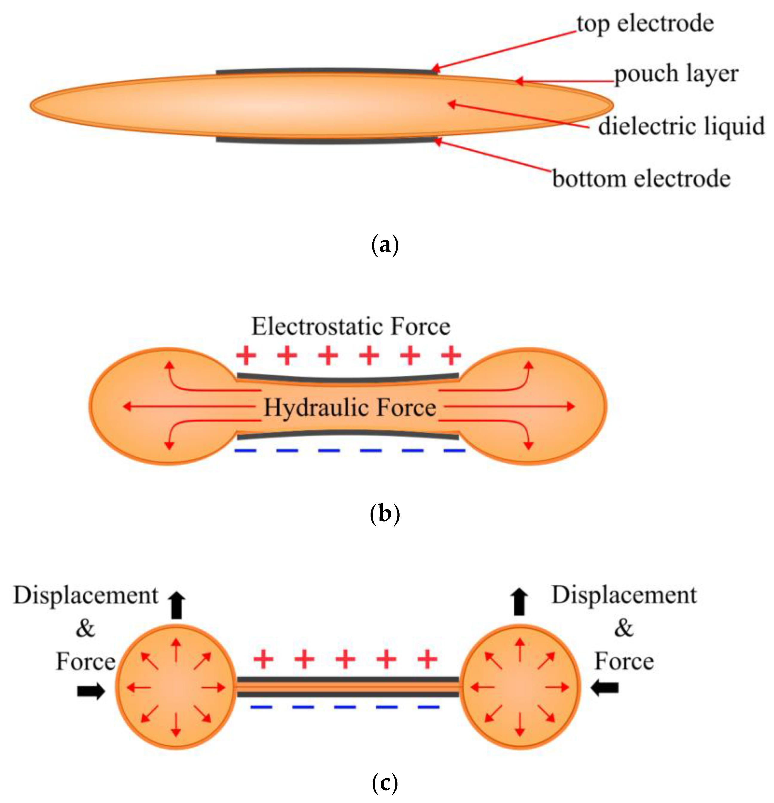
Figure 2.
Elastomeric donut HASEL actuator a) when at rest, showing the electrodes and pouch layer b) when a voltage is applied, indicating the direction of the force and displacement commonly used.
Figure 2.
Elastomeric donut HASEL actuator a) when at rest, showing the electrodes and pouch layer b) when a voltage is applied, indicating the direction of the force and displacement commonly used.
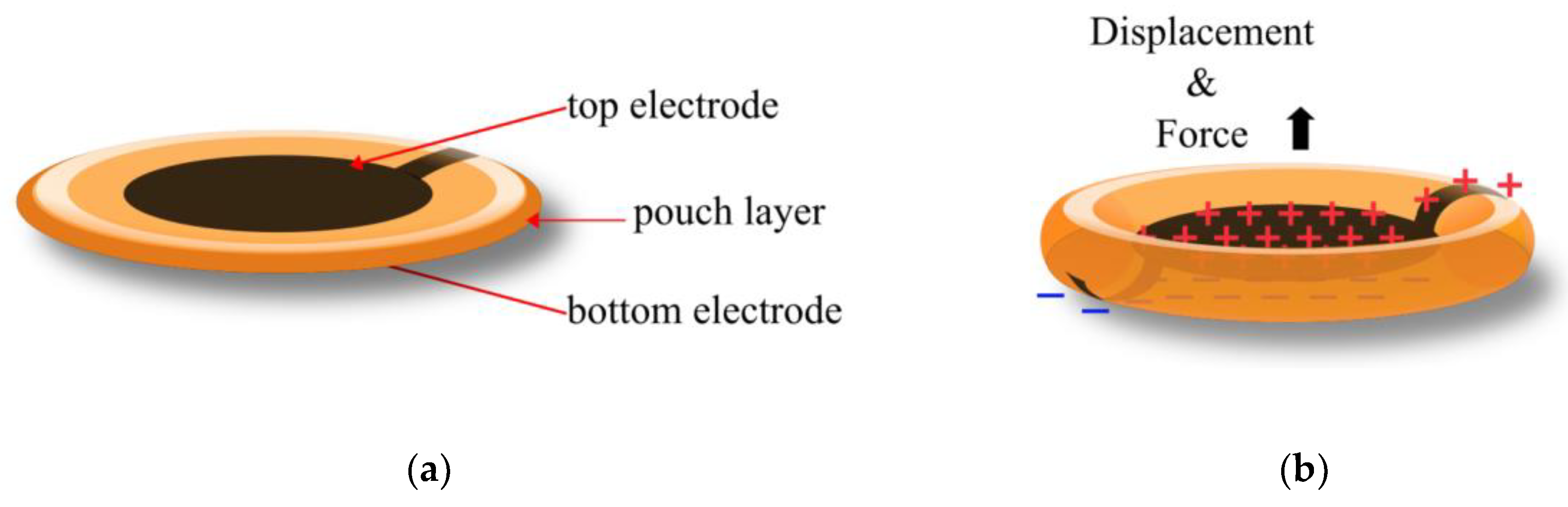
Figure 3.
Planar HASEL actuator, a) when at rest, displaying the electrode, pouch layer and the rigid frame; b) when a voltage is applied, indicating the direction that the force and displacement are commonly applied.
Figure 3.
Planar HASEL actuator, a) when at rest, displaying the electrode, pouch layer and the rigid frame; b) when a voltage is applied, indicating the direction that the force and displacement are commonly applied.
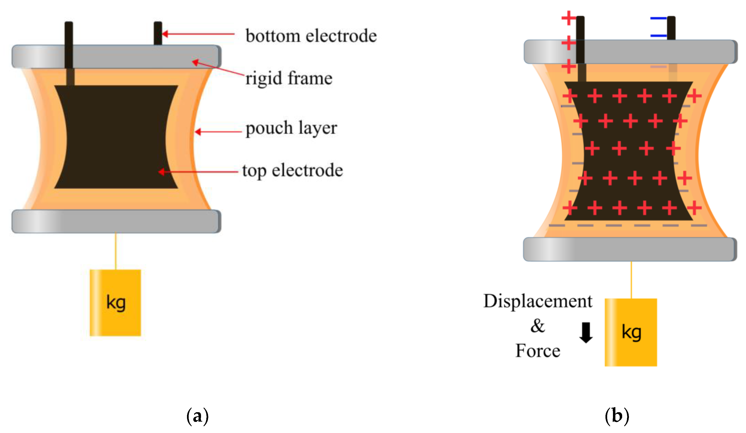
Figure 4.
Peano HASEL actuator a) with an initial applied voltage and electric field. b) initial zipping from a high field region. c) Fully zipped electrodes produce force and displacement.
Figure 4.
Peano HASEL actuator a) with an initial applied voltage and electric field. b) initial zipping from a high field region. c) Fully zipped electrodes produce force and displacement.
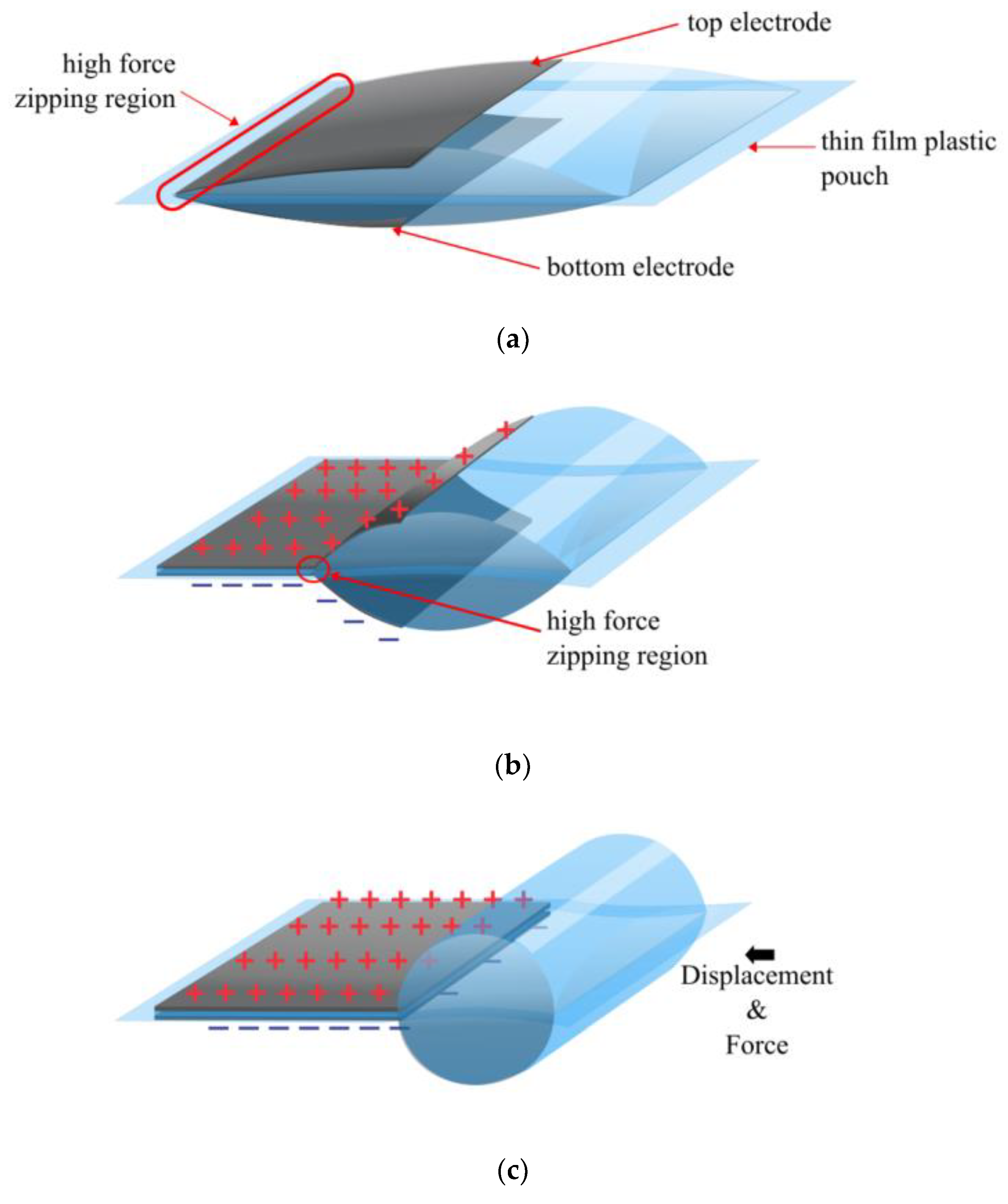
Figure 5.
Donut HASEL actuator, with two types of zipping regions. a) The dimple Donut HASEL actuator with only one zipping site, at rest; b) The dimple Donut HASEL actuator, when a voltage is applied; c) The Quadrant HASEL actuator with four lines of zipping sites; d) The Quadrant HASEL actuator, when a voltage is applied [14].
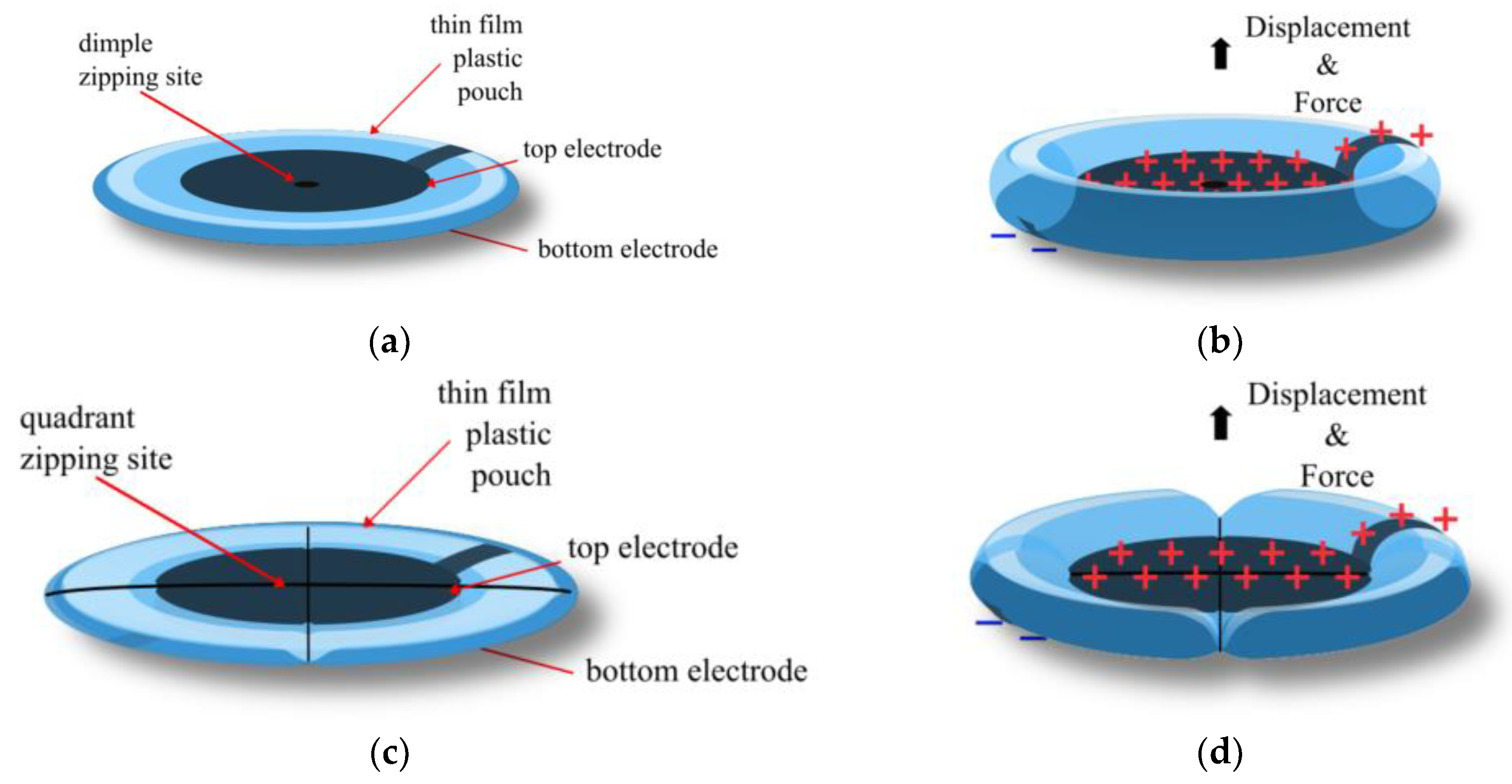
Figure 6.
Kellaris’ SES actuator a) when at rest, depicting the electrodes, rigid layers, thin film layers and the SES hinge. b) when a voltage is applied [15].
Figure 6.
Kellaris’ SES actuator a) when at rest, depicting the electrodes, rigid layers, thin film layers and the SES hinge. b) when a voltage is applied [15].
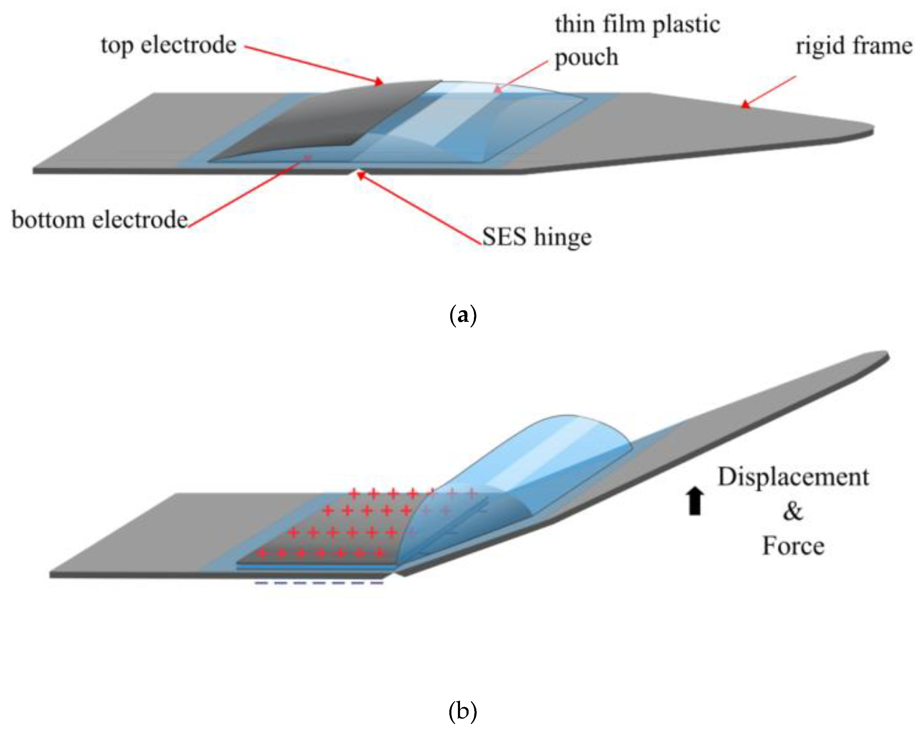
Figure 7.
Yoder’s HEXEL actuator a) when at rest, depicting the electrodes, rigid layers and thin film layers. b) when a voltage is applied [17].
Figure 7.
Yoder’s HEXEL actuator a) when at rest, depicting the electrodes, rigid layers and thin film layers. b) when a voltage is applied [17].
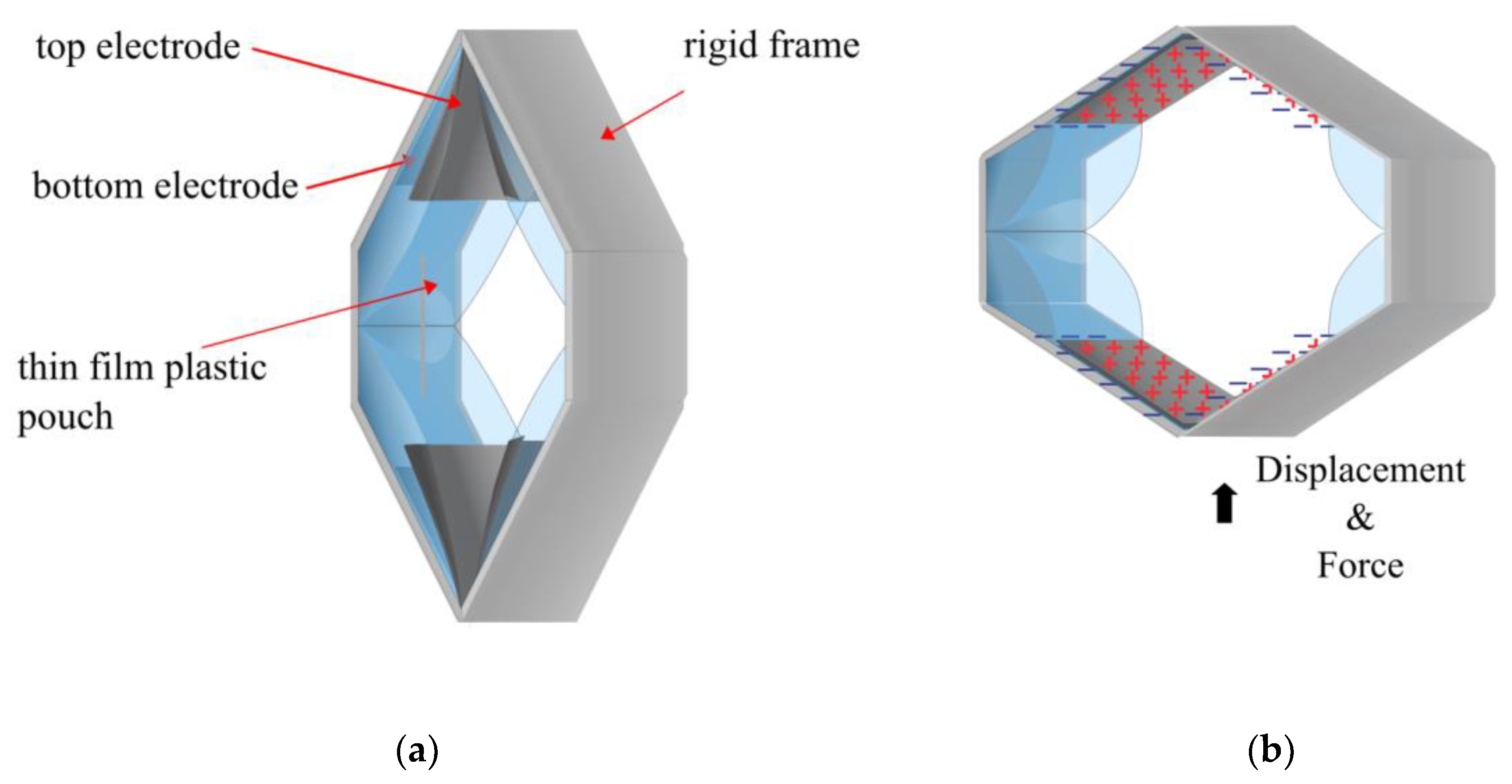
Figure 8.
Schematic of HAXEL actuator combining stretchable, compliant and rigid materials. a) Actuator with no voltage applied, and b) Actuator with voltage applied[19].
Figure 8.
Schematic of HAXEL actuator combining stretchable, compliant and rigid materials. a) Actuator with no voltage applied, and b) Actuator with voltage applied[19].
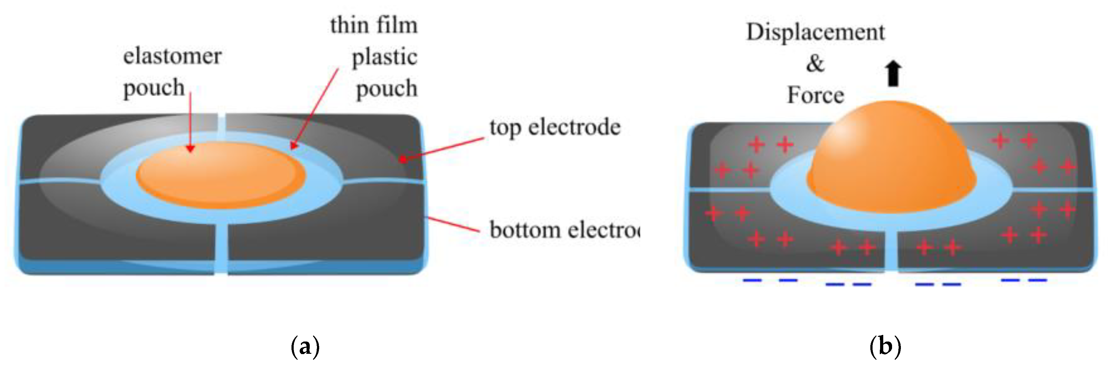
Figure 9.
LEAP actuator a) when at rest, b) a cross-sectional view of the actuator at rest, c) when a voltage is applied, d) a cross-sectional view of the actuator when a voltage is applied, demonstrating the direction of the force and displacement.
Figure 9.
LEAP actuator a) when at rest, b) a cross-sectional view of the actuator at rest, c) when a voltage is applied, d) a cross-sectional view of the actuator when a voltage is applied, demonstrating the direction of the force and displacement.
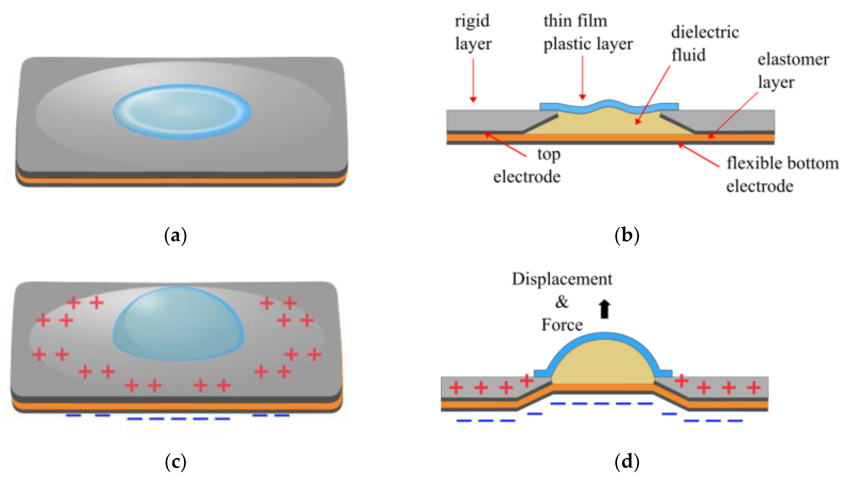
Figure 10.
Electrostatic Bellow Muscle actuator a) No voltage is applied, and the fluid is in the actuator b) A cross-sectional view of the actuator when at rest c) The actuator is fully zipped, and all of the fluid is now in the reservoir; d) The cross-sectional view when a voltage is applied[26].
Figure 10.
Electrostatic Bellow Muscle actuator a) No voltage is applied, and the fluid is in the actuator b) A cross-sectional view of the actuator when at rest c) The actuator is fully zipped, and all of the fluid is now in the reservoir; d) The cross-sectional view when a voltage is applied[26].
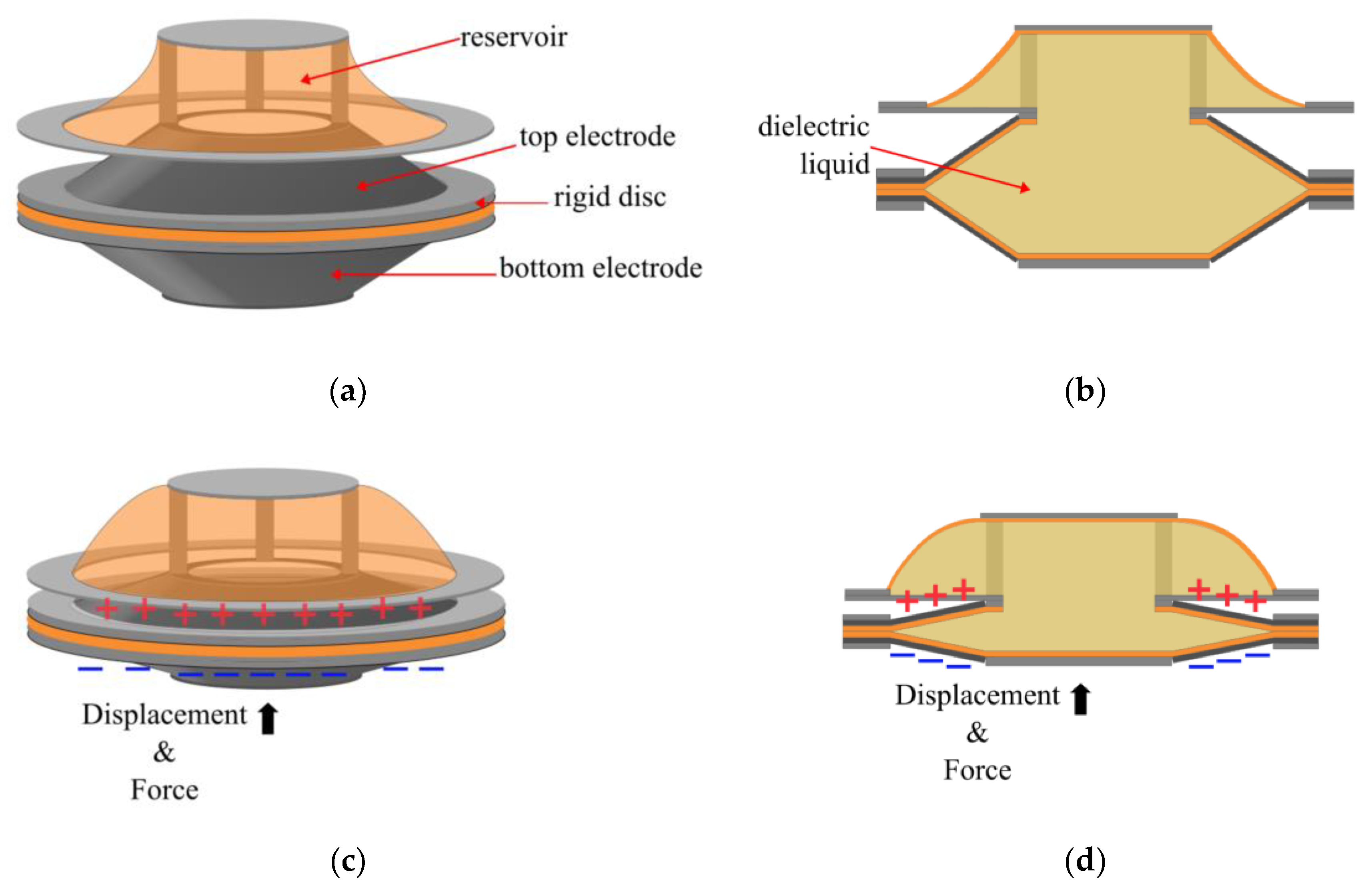
Figure 11.
Bluett’s Electro-ribbon actuator a) No voltage is applied, electrodes are bowed under the weight of the load, and the dielectric fluid is at the zipping region of the electrodes. b) A voltage is applied, and the electrodes are fully zipped together, dispersing the dielectric droplet along the length of the electrode [29].
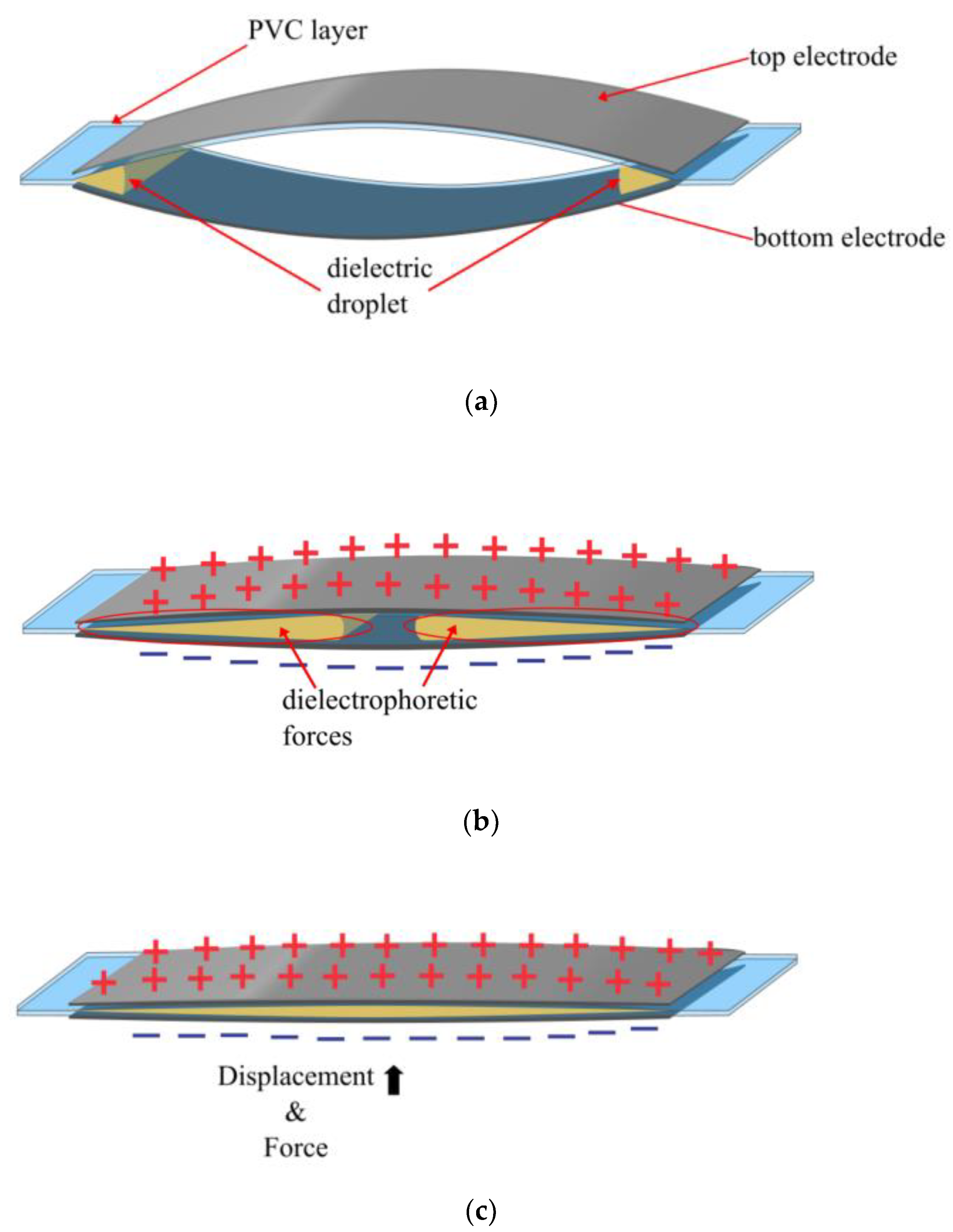
Figure 12.
Diteesawat’s Electro-Pneumatic Pump and BAM a) at rest and b) when a voltage is applied.
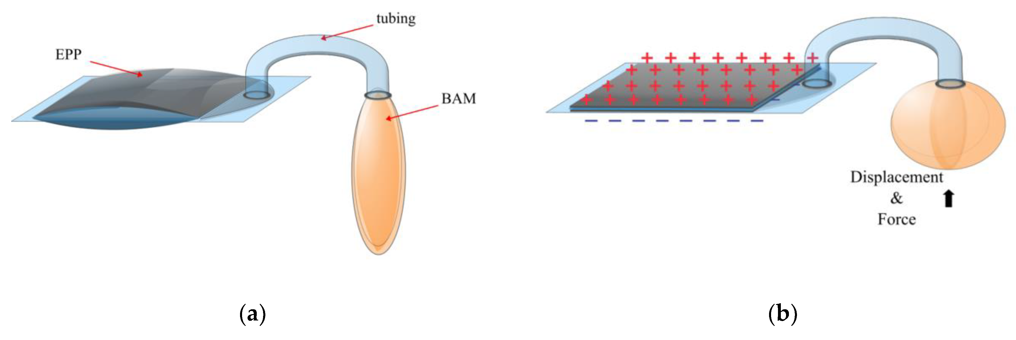
Figure 13.
Gravert’s HALVE actuator a) at rest; b) when a voltage is applied and the pouch is partially zipped c) when a voltage is applied and the pouch is fully zipped, displaying the direction of the force and the displacment[34].
Figure 13.
Gravert’s HALVE actuator a) at rest; b) when a voltage is applied and the pouch is partially zipped c) when a voltage is applied and the pouch is fully zipped, displaying the direction of the force and the displacment[34].
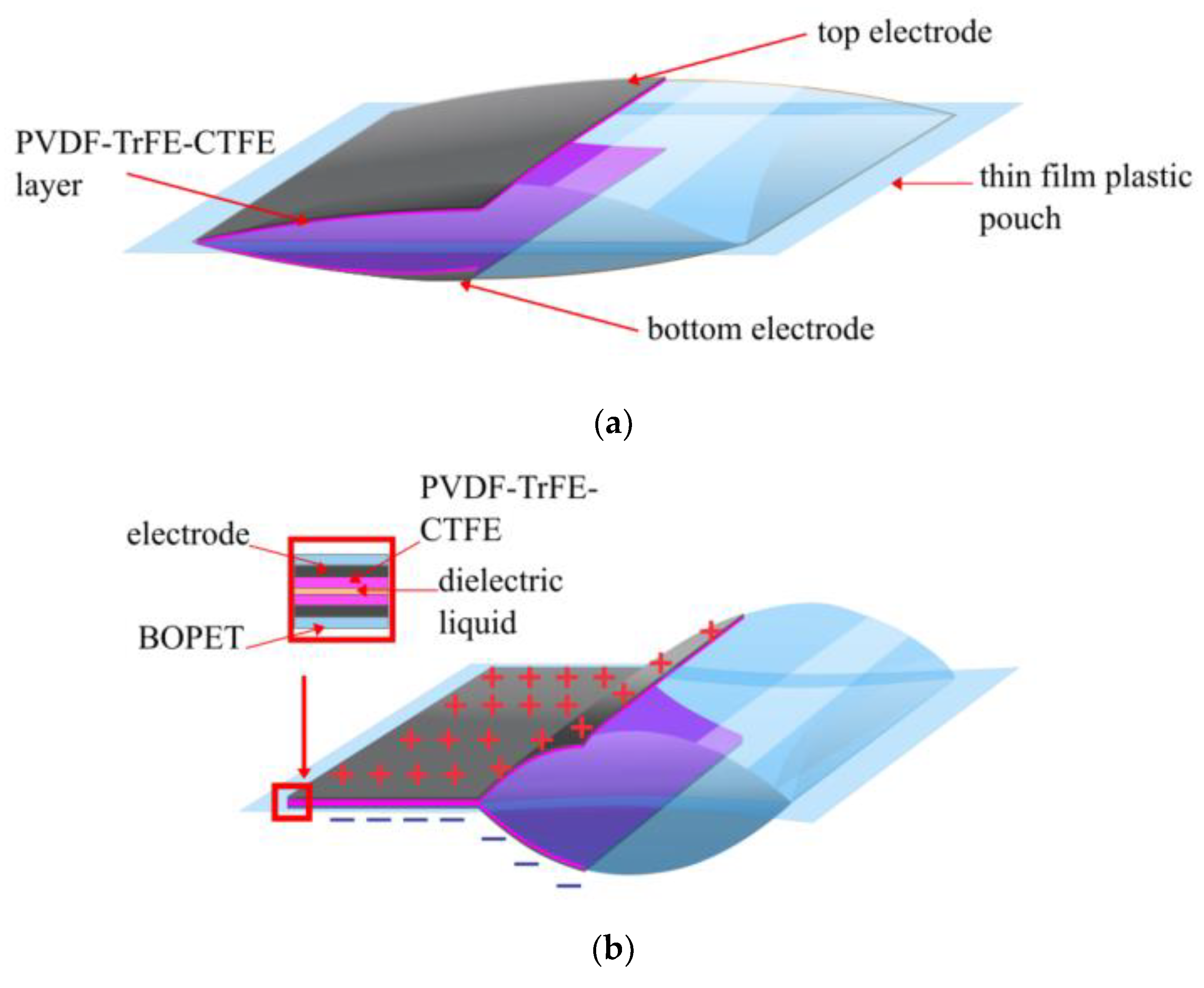
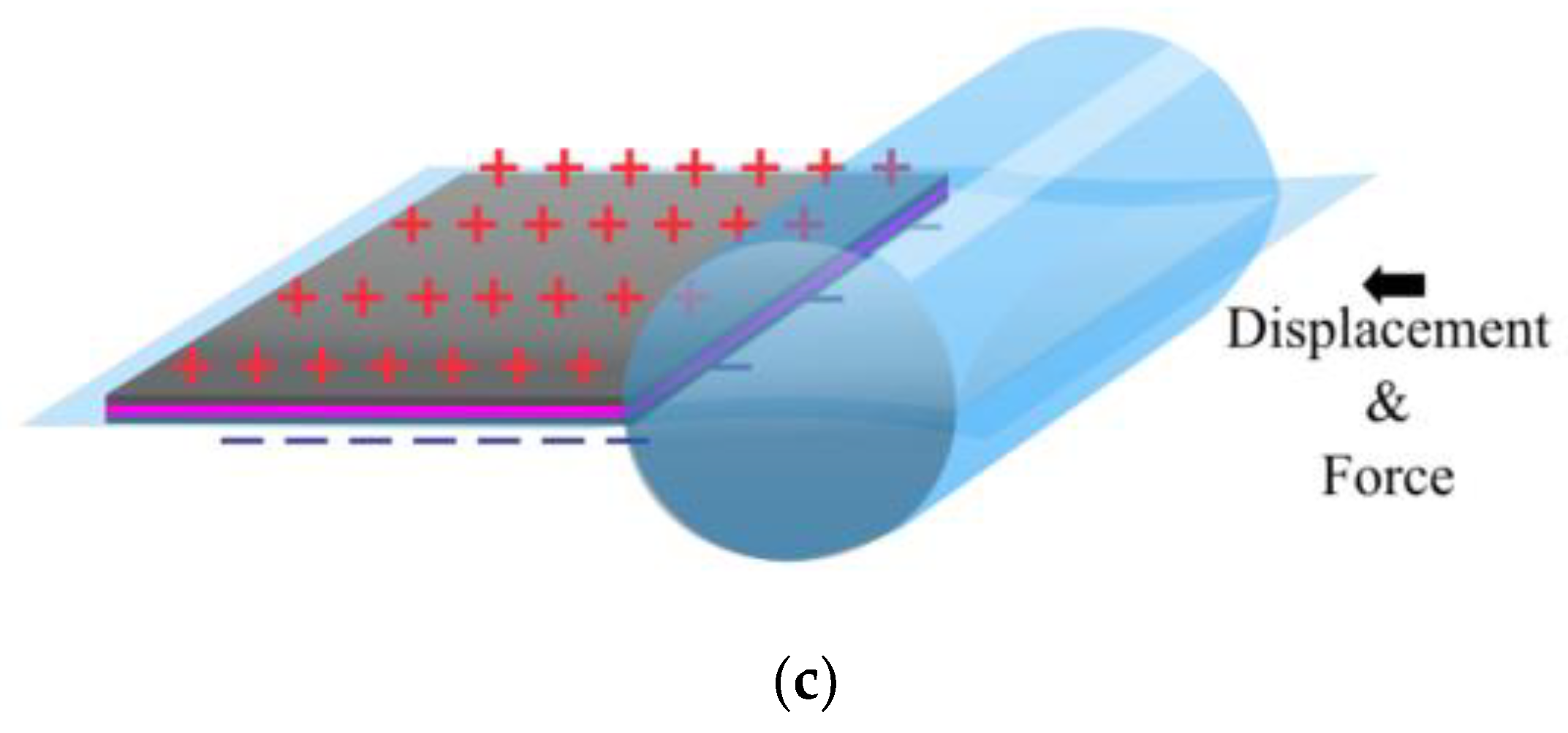
Figure 14.
Graph comparing the permittivity of the various materials to be used with the dielectric pouches over the years and their relationship to force production.
Figure 14.
Graph comparing the permittivity of the various materials to be used with the dielectric pouches over the years and their relationship to force production.
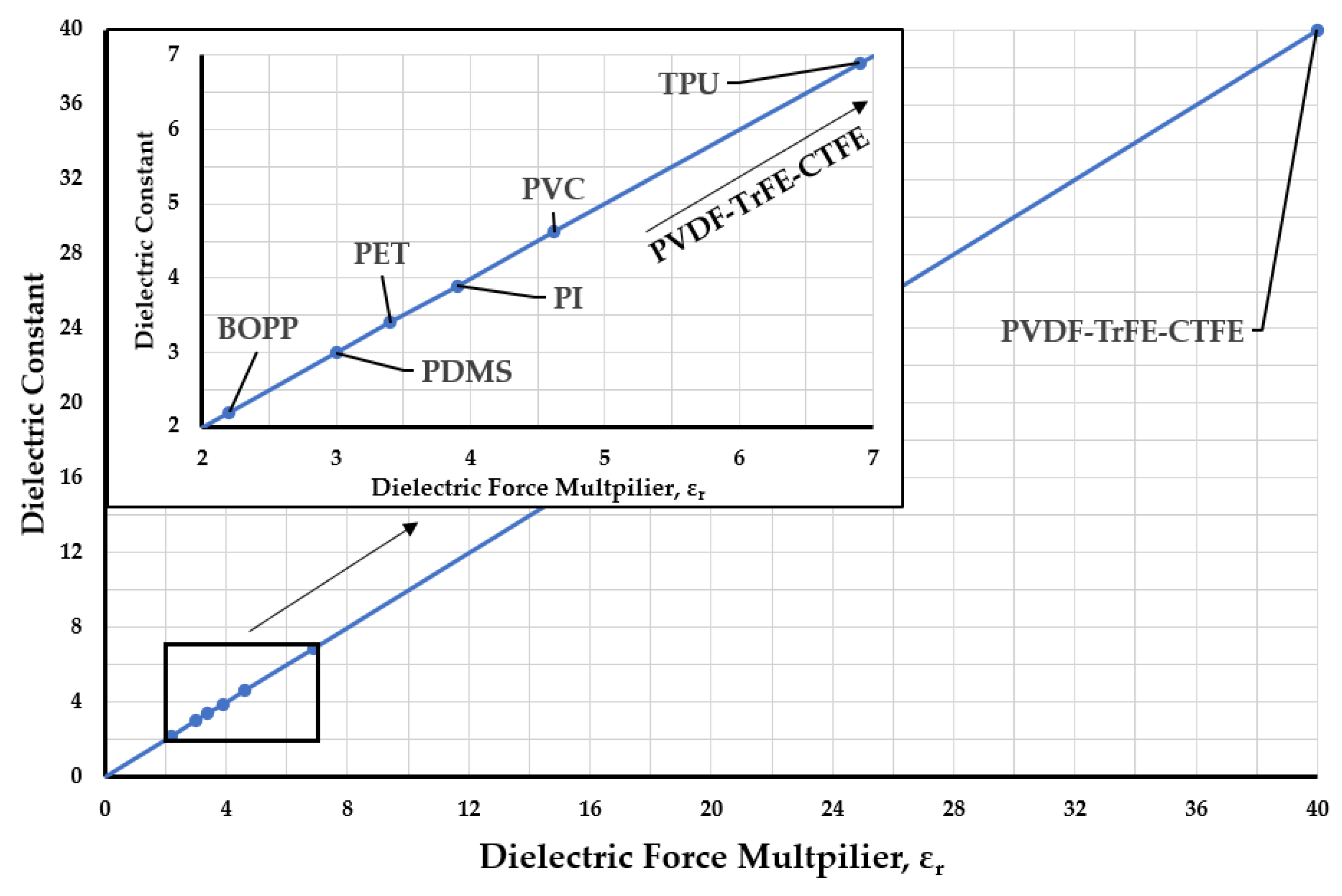
Figure 15.
Graph comparing the electrode gap of the various electrohydraulic actuators used for the dielectric pouches over the years and their relationship to force production.
Figure 15.
Graph comparing the electrode gap of the various electrohydraulic actuators used for the dielectric pouches over the years and their relationship to force production.
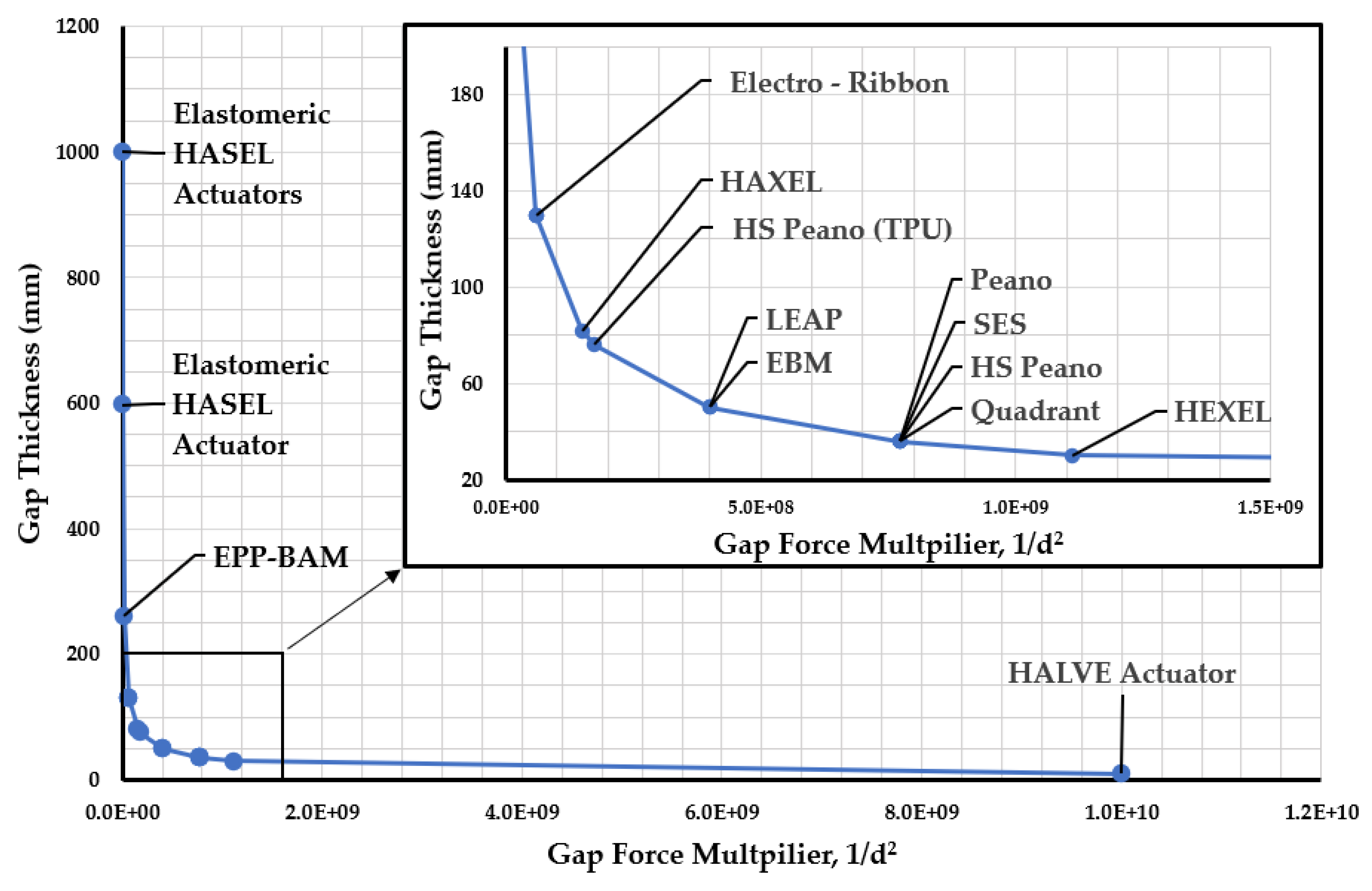
Figure 16.
Graph comparing the electrode gap with the relative permittivity of the various electrohydraulic actuators used for the dielectric pouches over the years and their relationship to force production.
Figure 16.
Graph comparing the electrode gap with the relative permittivity of the various electrohydraulic actuators used for the dielectric pouches over the years and their relationship to force production.
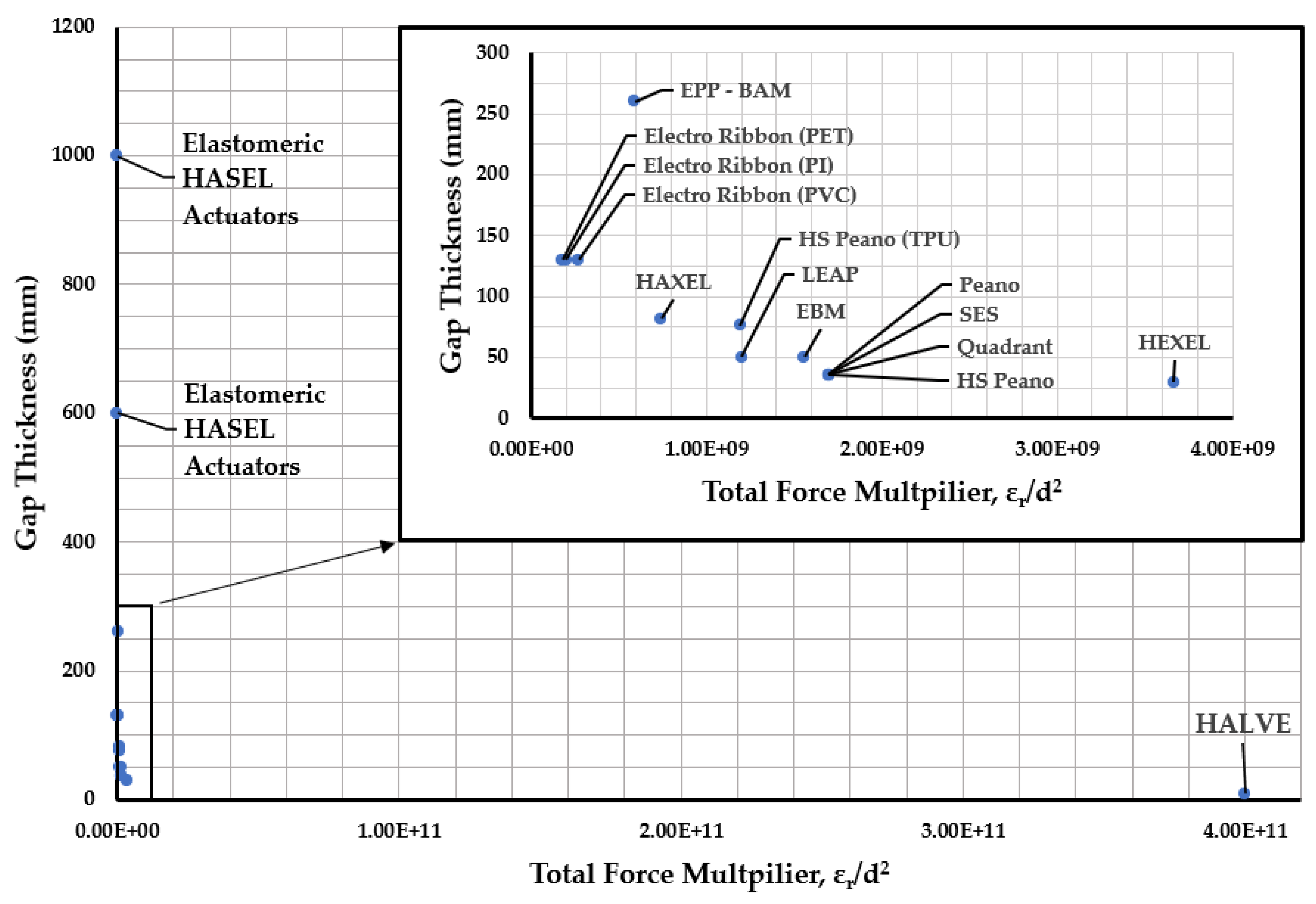

Table 1.
Expanding Electrohydraulic actuator metrics as reported over the years. Results from each university are displayed together. Only steady-state values are reported in the table. The table did not consider metrics reported from oscillating input voltages, like the Planar HASEL actuator.
Table 1.
Expanding Electrohydraulic actuator metrics as reported over the years. Results from each university are displayed together. Only steady-state values are reported in the table. The table did not consider metrics reported from oscillating input voltages, like the Planar HASEL actuator.
| Actuator | University | Applied Voltage (kV) | Max. Free Strain (%) | Max. Blocking Force (N) | Peak Specific Power (W/kg) | Peak Average Specific Power (W/kg) |
Specific Energy (J/Kg) |
| Elastomeric Donut HASEL actuator | University of Colorado Boulder | 21 | 40 – 50 | 2.45 – 3.92 | |||
| Planar HASEL actuator | University of Colorado Boulder | ~22.5 | 79 | 2.45-14.72 | 614 | 70 | |
| Three-stack Quadrant HASEL actuator | University of Colorado Boulder | 12 | 118 | ~60* | 121 | > 60 | 12 |
| HEXEL | University of Colorado Boulder | 9.5 | 113 | >2 | 90 | ~30 | |
| HAXEL | EPFL | 2 | 60 | 0.1 – 0.8 | 102 | 0.51 | |
| LEAP | University of Trento | 4.5 | 0.017 |
*The heat seal broke before at 60N.
Table 2.
Contracting electrohydraulic actuator metrics, as reported over the years. Results from each university are displayed together.
Table 2.
Contracting electrohydraulic actuator metrics, as reported over the years. Results from each university are displayed together.
| Actuator | Institution | Applied Voltage (kV) | Max. Free Strain (%) | Max. Blocking Force (N) | Peak Specific Power (W/kg) | Peak Average Specific Power (W/kg) |
Specific Energy (J/Kg) |
| Three-stack Peano HASEL actuator |
University of Colorado Boulder | 10 | 9 – 15 | 9.81 – 60 | 160 | > 50 | 4.93 |
| HS Peano HASEL actuator | University of Colorado Boulder | 10 | 24 | 18 | ~120 | ~78 | 4.03 |
| SES | University of Colorado Boulder | 9 | 230 | 110 | 10.3 | ||
| HEXEL | University of Colorado Boulder | 9.5 | 47.7 | 37.6 | 122 | 2.3 | |
| Three – Six series EBM | University of Trento | 8 | 43 | ~7* | 31 | ||
| Electro ribbon Actuator | University of Bristol | 10 | >99 | 0.172* | |||
| EPP-BAM | University of Bristol | 10 | 32.4 | 0.981* | 112.16 | 2.59 | |
| HALVE actuator | ETH Zürich | 1.1 | 9 | 5* | 50.5 |
* This was the maximum force reported, not necessarily the blocking force.
Table 3.
Displays all the dielectric pouch materials used in the electrohydraulic research discussed in this paper.
Table 3.
Displays all the dielectric pouch materials used in the electrohydraulic research discussed in this paper.
| Actuator | Institution | Dielectric Material | Dielectric Thickness (µm) | Dielectric Layers |
Total Dielectric Gap (µm) |
Relative Permittivity |
Compliant/ Elastomeric |
| Elastomeric Donut HASEL Actuator |
University of Colorado Boulder | Ecoflex | 500 | 2 | 1000 | 2.3 – 3 | Elastomeric |
| PDMS | 300 | 2 | 600 | 2.3 – 3 | Elastomeric | ||
| Elastomeric Donut HASEL Actuator |
University of Colorado Boulder | Ecoflex | 500 | 2 | 1000 | 2.3 – 3 | Elastomeric |
| PDMS | 300 | 2 | 600 | 2.3 – 3 | Elastomeric | ||
| Peano HASEL actuator |
University of Colorado Boulder | BOPP | 18 – 21 | 2 | 42 | 2.2 | Compliant |
| HS Peano HASEL Actuator | University of Colorado Boulder | BOPP | 18 | 2 | 36 | 2.2 | Compliant |
| TPU | 38 | 2 | 76 | 6.9 | Elastomeric | ||
| Quadrant HASEL Actuator | University of Colorado Boulder | BOPP | 18 | 2 | 36 | 2.2 | Compliant |
| SES | University of Colorado Boulder | BOPP | 18 | 2 | 36 | 2.2 | Compliant |
| HEXEL | University of Colorado Boulder | PET | 15 – 30 | 2 | 30 – 60 | 3.3 | Compliant |
| HAXEL | EPFL | PET | 12 50 – 100* |
1 1 |
82 – 132 | 3.3 | Compliant |
| PVDF-TrFE-CTFE, | 5 15* |
1 1 |
38 | Compliant | |||
| LEAP | University of Trento | PDMS | 50 | 1 | 50 | 2.3 – 3 | Elastomeric |
| EBM | University of Trento | PI | 25 | 2 | 50 | 3.9 | Compliant |
| Electro ribbon Actuator | University of Bristol | PET | 130 | 1 | 130 | 3 – 3.4 | Compliant |
| PI | 130 | 1 | 130 | 3.4 – 3.5 | Compliant | ||
| PVC | 130 | 1 | 130 | 4.62 | Compliant | ||
| EPP-BAM | University of Bristol | PVDF-TrFE-CTFE | 130 | 2 | 260 | 40 | Compliant |
| HALVE Actuator | ETH Zürich | PVDF-TrFE-CTFE | 5 | 2 | 10 | 40 | Compliant |
*Bottom layer dielectric.
Disclaimer/Publisher’s Note: The statements, opinions and data contained in all publications are solely those of the individual author(s) and contributor(s) and not of MDPI and/or the editor(s). MDPI and/or the editor(s) disclaim responsibility for any injury to people or property resulting from any ideas, methods, instructions or products referred to in the content. |
© 2025 by the authors. Licensee MDPI, Basel, Switzerland. This article is an open access article distributed under the terms and conditions of the Creative Commons Attribution (CC BY) license (http://creativecommons.org/licenses/by/4.0/).
Copyright: This open access article is published under a Creative Commons CC BY 4.0 license, which permit the free download, distribution, and reuse, provided that the author and preprint are cited in any reuse.


