
Submitted:
25 January 2025
Posted:
28 January 2025
You are already at the latest version
Abstract
A growing interest in microphone arrays technology has been observed in the automotive industry, e.g. for the development of immersive infotainment systems or Active Noise Control (ANC) systems. However, the human presence always limits the usage of microphone arrays in driving conditions at driver seat. The latter being often the most important position of the car cabin, a wearable microphone array is particularly interesting. In this paper, a wearable helmet microphone array is presented: it features 32 microphones arranged over the surface of a helmet, which also integrates a specifically designed Analog-to-Digital (A/D) converter, delivering digital signals over the Automotive Audio Bus (A2B). Digital signals are collected using a control unit located in the passenger compartment, that can either deliver digital signals to a personal computer or analog signals to an external acquisition system, by means of Digital-to-Analog (D/A) converters. A prototype was built and acoustically characterized to calculate the beamforming matrix required to convert the recordings (pressure signals) into Ambisonics signals (a spatial audio format). The proposed solution was compared to the reference spherical microphone array of the last decade, demonstrating a much better performance in sound source localization at low frequencies, where ANC systems are mainly effective.
Keywords:
Active Noise Control (ANC)
; Ambisonics
; Automotive Audio Bus (A2B)
; beamforming
; immersive audio
; infotainment systems
; microphone array
; spatial audio
; wearable helmet
1. Introduction
Microphone arrays are more and more employed in several fields, from electronic devices for dereverberation [1,2], speech enhancement [3,4] and speech recognition [5], to industries, for localizing noise sources [6,7] or machine condition monitoring [8,9], and even civil applications for structural health monitoring [10,11]. Recently, also the automotive industry has benefited of this technology, particularly for the development of Active Noise Control (ANC) systems [12], speaker identification in autonomous vehicles [13], improvement of infotainment systems [14,15] and enhancement of sound quality in car cabins [16,17].
When designing these systems, the geometry of the array plays a crucial role in determining the portion of space where it exhibits optimal accuracy, such as a line, a plane, a half-space, or the full sphere. As a result, microphone arrays having a variety of shapes were observed, such as linear [18], planar [19], cylindrical [20], despite mostly of them being spherical [21,22,23], namely Spherical Microphone Array (SMA). The dimension of the array is another key factor, since the larger the array, the lower the minimum frequency where beamforming is effective. Therefore, bigger arrays, either real or virtual, as in [24], are required for low frequency source localization. This is an important aspect to consider also in the automotive field when dealing with ANC applications, which are mostly effective at very low frequency, hence large arrays would be highly desirable.
Another fundamental feature for microphone array design is the number of capsules, as the closer are the microphones, the higher is the maximum beamforming frequency. As a consequence of this consideration, we have observed a trend towards the continuous appearance on the market of systems with an ever-increasing number of capsules. The layout of the capsules over the surface of the array is at least as important. A heuristic approach was used for planar arrays in [25], while several mathematical approaches have been developed for SMA, with the aim of optimizing the spatial sampling over the sphere, as well treated in [26]. In case of equiangular sampling, being O the desired Ambisonics order, the number N of required microphones is given by (1), while in case of nearly uniform sampling, is given by (2):
Other interesting distributions of points are based on regular polyhedrons, such as tetrahedron, dodecahedron and icosahedron, with N = 4, 20, 12, respectively. The Eigenmike32 [27], widely recognized as the reference system of the last decade and employed as reference system within the presented work, features thirty-two capsules arranged in a truncated icosahedron.
When selecting the type of capsule, analog transducers can provide high-quality audio signals, but they come with some drawbacks, such as cumbersome wiring and susceptibility to noise interference, especially when long cables are used to connect the capsules to the Analog-to-Digital (A/D) converters. On the other hand, affordable digital Micro Electro-mechanical Systems (MEMS) microphones tend to be more resistant to electrical interference, though this often comes at the expense of lower acoustic performance, such as reduced dynamic range and signal-to-noise ratio.
In this work, a wearable microphone array was developed and built, by using a normal helmet as frame. Such a solution allows for recording 3D audio signals at driver seat also in driving conditions, which is a particularly desirable condition for the development of ANC systems on cars. The dimension of the helmet, which is much larger than any microphone array currently available, allow for shifting the frequency range of beamforming toward low frequencies, where ANC systems are mostly effective, i.e. 50 Hz – 400 Hz, as referred in [28]. The nearly uniform sampling theory was employed to optimize the distribution of the capsules over the surface of the array. A Spherical Design [29,30,31] distribution of order seven, hence with 32 points was employed. The proposed solution features electret capsules connected to a miniaturized A/D converter incorporated in the helmet. The A/D converter also integrates an A2B transceiver, allowing to deliver digital signals over an Ethernet cable, thus ensuring immunity to electromagnetic disturbances, always present in a car cabin.
The paper is arranged as follow: Section II describes the development of the helmet, the acoustical characterization and the architecture of the electronics; Section III illustrates the main findings obtained within this work; in Section IV the results are discussed and finally, Section V summarizes the conclusions.
2. Materials and Methods
2.1. Array Helmet Design
The first step of the development consisted in the choice of the helmet, which must be as spherical as possible, with a smooth surface without any holes, grids, vents, knobs and protruding parts to avoid any practical limitation for capsule mounting. This led to the choice of the model X3000 by the Italian manufacturer AGV (Figure 1).
The microphonic capsule chosen to build the array is the model AOM-5024L-HD-R from PUI Audio, whose technical specifications are reported in Table 1. It has a very low self-noise of just 14 dB(A) and more than 90 dB(A) of dynamic range. In Figure 2 (provided by the manufacturer), one can note the frequency response is almost flat in the interested frequency range, which is 20 Hz – 1 kHz.
A 3D model of the helmet was acquired with the laser scanning technique, by employing a Shining 3D EinScan H2. The result was stored as stereolithography file, namely stl (also referred as standard triangle language or standard tessellation language). In this way, it was possible to easily import and manipulate the geometry in Matlab. To define the optimal distribution of the capsules, the nearly uniform sampling was adopted. The geometrical center of the model was calculated, letting 32 straight lines propagating from it in the same directions of a spherical design of order T = 7, featuring N = 32 points [32,33]. Such bundle of lines was rotated to minimize the intersections with the areas where it was not possible to mount any capsules, namely the visor and the hole for the neck. The minimum number of unallowed points was six, two on the visor and four on the neck. These points were manually repositioned. Finally, 10 mm diameters holes were drilled by using a computer numerical control (CNC) machine and the capsules were fixed in positions by using a special adhesive modeling paste. The result can be seen in Figure 3 (left).
2.2. Acoustics Characterization of the Array Helmet
Once assembled, the helmet was characterized in the acoustics laboratory at the University of Parma, Parma (Italy). The measurement procedure made use of a two-axis turntable and a loudspeaker (Genelec studio monitor type 8351a) in a fixed position (Figure 3, right). Since the helmet must be used in a small environment, the measurement was performed at a very short distance, 0.5 m, to consider the near-field effect provided by the curvature of the sound waves [34], thus optimizing the beamforming for the car cockpit. The test signal employed was an Exponential Sine Sweep (ESS) [35], pre-equalized for flatting the spectrum (+/- 1 dB in the range 50 Hz – 20 kHz). At each repetition of the measurement, the helmet is automatically rotated by the turntable in a specific direction d, and the test signal is recorded by the N capsules of the array. This procedure also addresses the problem of spatial sampling of a sphere and has been solved again with the nearly uniform sampling but using a considerably larger number of points. A set of D = 240 directions was used to characterize the acoustic response of the array helmet, corresponding to a spherical design of order T = 21.
The above measurement provides the matrix C of eq. (3), which consists in the regularized Kirkeby inversion [36], a linear processing employed to compute a beamforming matrix of Finite Impulse Response (FIR) filters. In frequency domain, it is defined as:
where C is the frequency response of the array for the N capsules, D directions and K frequencies, * is the Hermitian transpose, · is the scalar product, β is a parameter that varies with frequency for regularized inversion [37], I is the identity matrix, -1 is the pseudo-inverse, e-jπk introduces a delay to guarantee the causality of the filters, k is the frequency. Matrix A represents the desired directivity patterns of the virtual microphones encoded by the beamformer. It does not depend on the frequency and must be defined by the user for each measured direction d of the matrix C and for all the N capsules. In our case, it corresponds to the first v = 16 Spherical Harmonics (SH) employed by the Ambisonics format at order 3. SH are mathematical functions obtained as a complex combination of sound pressure and particle velocity, approximating the sound field in the recording point [38,39]. The 3D polar patterns of the first 16 SH (Ambisonics 3rd order) are shown in Figure 4.
The virtual microphones, i.e. SH, are then obtained by means of convolution, which is the multiplication in frequency domain:
Note that only in the ideal case of perfect reconstruction of the SH, it will result A’ = A at all frequencies, while in the real case, A’ will always approximate A.
2.3. Electronics Design
The system, whose scheme is depicted in Figure 5, is composed of the helmet, which houses the microphones and the electronic board to collect the signals, and a digital-to-analog (D/A) box, which can be connected either to a personal computer (PC) or an external acquisition system. It must be noted that when a PC is employed, the entire system (after A/D conversion) is full-digital, while a double A/D and D/A conversion is introduced when an external recording system must be employed. However, this solution guarantees a robust signal-to-noise (S/N) ratio inside the car cockpits, which are electrically noisy.
The system was designed to use the A2B bus by Analog Devices [40], which can handle up to 32 channels on a single Unshielded Twisted Pair (UTP), up to 15 meters distance. An A2B network consists of a main node and up to 10 subordinate nodes arranged in daisy-chain. Dedicated transceivers handle bus access and data flow, eliminating the need for extra devices that would add to the cost and complexity of the system. An A2B network provides a bandwidth of 50 Mbit/s, enabling the transmission of up to 32 channels at the standard sample rate of 48 kHz with 16-, 24-, or 32-bits resolutions. This digital bus is particularly suitable for transmitting audio signals in both microphone and loudspeaker arrays [41], as it guarantees a deterministic latency of just two samples at 48 kHz and the synchronization between all the channels [42,43].
The electronic board installed in the helmet (scheme depicted in Figure 6, left) is provided with eight 4-channels, 16 bits, audio A/D converters, type TLV320ADC6140 by Burr-Brown, and it also integrates the A2B transceiver to acquire and deliver the data via A2B bus. The A/D converters (specification are reported in Table 2) are connected to the transceiver via two Time-Division Multiplexing (TDM) 4 digital lines (TDM0 and TDM1 in Figure 6). The signals are transferred from the helmet to the D/A box unit over an Ethernet cable that carries also the 5 Vdc power supply for the helmet board. The ethernet cable was chosen as the physical layer of the A2B bus, being cheap and common, with robust connectors that are easy to insert and remove. Note that a standard Ethernet cable includes four UTP cables, of which one is used for the A2B bus and one for the power supply. The ethernet socket mounted on the helmet can be seen in Figure 6, right.
The D/A box, whose schematic is shown in Figure 7 and the prototype can be seen in Figure 8, right, receives the digital signals from the A2B bus, and then either transmits them to a PC via Universal Serial Bus (USB) or converts them back to analog signals to be recorded by an external acquisition system connected via BNC connectors (Figure 8, left). The D/A box is made of two boards: an A2B main board and an A2B subordinate board. The A2B main board generates the A2B network, provides the clock to the A2B subordinate board, and can be connected to the PC to deliver the digital data via USB. The A2B subordinate board features two 16-channels, 16 bits, D/A converters, type ADAU1966 by Analog Devices (specifications are resumed in Table 3), to deliver analog signals to an external acquisition system, such as the Siemens SCADA, a standard equipment in automotive Noise, Vibration and Harshness (NVH). In addition, the D/A box produces all the supply voltages for the system, starting from the 12 V on-board battery of the vehicle. To isolate the system from disturbances in the vehicle's electrical system, which is usually noisy, all the regulators are designed to ensure full galvanic insulation.
3. Results
At first, the beamforming capability of the proposed array helmet was compared to the Eigenmike32. The comparison was made by using a metric proposed in [44], which consists in evaluating the deviation of the directivity A’ with respect to the ideal directivity defined by A. This can be done by relying on two parameters, the Spatial Correlation (SC), which sets the limit of the beamforming at high frequency and is the defined in (5), and the Level Difference (LD), which sets the limit of the beamforming at low frequency and is defined in (6):
The parameters are calculated for each frequency, each direction, and each virtual microphone, then the D directions are summed, while the virtual microphones are averaged among those belonging to the same Ambisonics order. Hence, from 1 to 4 in the 1st order, from 5 to 9 in the 2nd order and from 10 to 16 in the 3rd order. In the ideal case of perfect reconstruction of the SH, it will be SC = 1 and LD = 0 dB. However, a certain amount of deviation is always accepted in the real case, hence the upper and lower frequency limits of the beamforming are usually defined by considering two thresholds: SC > 0.9 and LD < -1 dB. The results are shown in Figure 9 for the Eigenmike32 and in Figure 10 for the array helmet.
Then, a localization test was performed in the acoustic laboratory at the University of Parma, Parma (Italy), using the sound color mapping technique [45,46]. The array helmet was mounted on a microphone stand, in front of the Genelec studio monitor playing a pink noise, a 30 s signals was recorded and converted into Ambisonics 3rd order. Then, the array helmet was replaced with a dual lenses camera to take a 360° picture of the environment, which is used as background of the sound color maps. The analysis was performed in the octave bands centered at 31.5 Hz, 63 Hz, 125 Hz, 250 Hz, 500 Hz, 1 kHz. The color maps are calculated by using the Plane Wave Decomposition (PWD) algorithm [47,48]. The quantity being mapped is the Sound Pressure Level (SPL), calculated with a resolution of 2 degrees. The pseudo-color map is generated through graphical interpolation of the raw data, with a color scale that goes from blue (lowest SPL value) to red (highest SPL value). The results are shown in Figure 11.
4. Discussion
First, let’s consider the SC and LD charts of Figure 9 and Figure 10. From a qualitative point of view, it is possible to note that the SC of the Eigenmike32 remains almost equal to 1 up to much higher frequencies respect to the array helmet. This is thanks to the small size of the array, a sphere of 84 mm diameter, which allows to reduce significantly the minimum distance between the capsules, . The maximum theoretical beamforming frequency, , can be calculated as:
where c = 343 m/s is the celerity of the sound wave. By replacing in (7), we get . However, also the LD is shifted toward high frequencies. In fact, the Eigenmike32 is small if compared to the wavelengths at very low frequency, thus limiting the beamforming. Since the beamforming at low frequency mainly relies on the phase differences rather than the time of arrivals, which are directly related to the dimension of the array, it is not possible to easily predict the minimum frequency with an easy formula.
Conversely, the array helmet behaves in the opposite way. The value of the SC is < 1 at much lower frequencies respect to the Eigenmike32, being the array helmet much larger but having the same number of capsules of the Eingemike32. As a consequence, the minimum distance between the capsules becomes now , causing the spatial aliasing to occur at lower frequencies. By replacing this value in (5), we get for the array helmet. At the same time, the LD is significantly shifted toward low frequencies too, thanks to the dimension of the array helmet, which allows to increase the maximum distance between the capsules.
A quantitative analysis can be done by considering the thresholds defined for the SC and LD parameters. This allows us to accurately determine the minimum and maximum frequencies of the beamforming at each Ambisonics order. The results are presented in Table 4. As one can note, the array helmet only works up to 1 kHz, however this frequency perfectly fits the application, as ANC systems are effective up to about 400 Hz for wide band applications (e.g., road noise) and up to about 700 Hz for tonal applications (e.g., engine noise). On the other hand, the beamforming capability is considerably shifted toward low frequencies, and in particular:
- 1st order Ambisonics already available in the first octave band (central frequency is 31.5 Hz), while it was only available from the second octave band (central frequency is 63 Hz) with the Eigenmike32 and there was no beamforming capability in the first octave band.
- 2nd order Ambisonics already available in the second octave band (central frequency is 63 Hz), while it was only available from the fourth octave band (central frequency is 250 Hz) with the Eigenmike32.
- 3rd order Ambisonics already available in the fourth octave band (central frequency is 250 Hz), while it was only available from the sixth octave band (central frequency is 1 kHz) with the Eigenmike32.
In conclusion, an improvement of one octave band was obtained for the 1st order Ambisonics, and an improvement of two octave bands was obtained for the 2nd and 3rd orders Ambisonics, at the price of limiting the beamforming up to 1 kHz. These results are summarized in Table 5.
Based on the above results, we can now consider the second experiment, related to the localization of a noise source through sound color mapping. As can be seen in Figure 11, the array helmet correctly localized the sound source (Genelec studio monitor) even at the first octave band, where only the 1st order Ambisonics is available. In fact, the red spot of the color map is well centered on the noise source. At 125 Hz, when the 2nd order Ambisonics becomes available, several reflections can be seen, e.g., the glass cabinet (90°;0°), the door (135°; 0°), the desk (-100°; -30°). At 250 Hz the 3rd order Ambisonics starts to contribute, making the spot on the noise source narrower. Two reflections can be seen, on the floor and on the ceiling. Furtherly increasing the frequency, i.e. at 500 Hz and 1 kHz, the main spot on the noise source becomes even narrower.
5. Conclusions
A wearable helmet microphone array featuring 32 electret capsules has been developed, built and successfully tested. It integrates a miniaturized 32-channel A/D converter, which avoids the bulky wiring that would occur with an analog solution and ensures a high S/N ratio thanks to the usage of the A2B digital bus. In addition, this solution allows only one Ethernet cable to come out of the helmet, maintaining good comfort and ease of use. The A2B signal is received by an external D/A box, which can deliver digital data to the PC via USB or convert the data back to analog domain by means of two D/A converters, allowing to record them with an external acquisition unit.
The array helmet was compared with the Eigenmike32, a spherical microphone array widely considered the reference equipment for spatial audio recording during the last decade. By analyzing two metrics for Ambisonics performance evaluation, namely Spatial Correlation and Level Difference, it was possible to assess that the proposed system shifted toward low frequencies the Ambisonics orders by one or even two octaves, making it accurate even at the lowest octave band, centered at 31.5 Hz, where the Eigenmike32 is not effective at all. These results have been proved with a laboratory test consisting in a noise source localization problem, making use of the sound color mapping technique. The array helmet demonstrated to correctly localize the noise source at all frequencies, with a trend of increasing accuracy with frequency, as expected.
The highest valid frequency for beamforming has been reduced to 1 kHz, due to the large size of the helmet compared to the number of capsules. However, such frequency is still above the maximum frequency at which Active Noise Control systems for cars are effective. In conclusion, the proposed solution can be successfully employed for the assessment and the development of road noise cancelling or engine order cancelling systems, at the driver seat in driving condition.
6. Patents
A patent request was submitted for the presented work, application number US 18/519,990.
Author Contributions
Conceptualization, A.F. and J.P.; methodology, A.F.; software, D.P.; validation, D.P. and A.T.; formal analysis, A.F.; investigation, A.T. and D.P.; resources, J.P.; data curation, D.P.; writing—original draft preparation, D.P. and A.T.; writing—review and editing, A.F., A.T., M.B. and J.P.; visualization, D.P.; supervision, A.F.; project administration, A.F. and J.P.; funding acquisition, A.F. All authors have read and agreed to the published version of the manuscript.
Institutional Review Board Statement
Not applicable.
Data Availability Statement
The datasets presented in this article are not readily available because subjected to industrial secrecy. Requests to access the datasets should be directed to jspark@hyundai.com
Acknowledgments
The authors are grateful to Hyundai Motor Company for the economic support that made this research possible.
Conflicts of Interest
The authors declare no conflicts of interest.
Abbreviations
The following abbreviations are used in this manuscript:
| A2B | Automotive Audio Bus |
| A/D | Analog-to-Digital |
| ANC | Active Noise Control |
| CNC | Computer Numerical Control |
| D/A | Digital-to-Analog |
| DC | Direct Current |
| DSP | Digital Signal Processing |
| ESS | Exponential Sine Sweep |
| FIR | Finite Impulse Response |
| LD | Level Difference |
| MEMS | Micro Electro-mechanical Systems |
| NVH | Noise, Vibration and Harshness |
| PC | Personal Computer |
| PWD | Plane Wave Decomposition |
| S/N | Signal-to-Noise |
| SC | Spatial Correlation |
| SH | Spherical Harmonics |
| SMA | Spherical Microphone Array |
| SPL | Sound Pressure Level |
| TDM | Time-division multiplexing |
| USB | Universal Serial Bus |
| UTP | Unshielded Twisted Pair |
References
- F. Tan, C. Bao, and J. Zhou, “Effective Dereverberation with a Lower Complexity at Presence of the Noise,” Applied Sciences, vol. 12, no. 22, p. 11819, Nov. 2022. [CrossRef]
- O. Schwartz, S. Gannot, and E. A. P. Habets, “Multi-Microphone Speech Dereverberation and Noise Reduction Using Relative Early Transfer Functions,” IEEE/ACM Trans Audio Speech Lang Process, vol. 23, no. 2, pp. 240–251, Feb. 2015. [CrossRef]
- J. Xi, Z. Xu, W. Zhang, L. Zhao, and Y. Xie, “Speech Enhancement Algorithm Based on Microphone Array and Lightweight CRN for Hearing Aid,” Electronics (Basel), vol. 13, no. 22, p. 4394, Nov. 2024. [CrossRef]
- T. Tao et al., “Sound Localization and Speech Enhancement Algorithm Based on Dual-Microphone,” Sensors, vol. 22, no. 3, p. 715, Jan. 2022. [CrossRef]
- A. Valladares-Poncela, P. Fraga-Lamas, and T. M. Fernández-Caramés, “On-Device Automatic Speech Recognition for IIoT and Extended Reality Industrial Metaverse Applications,” in ICSEE 2024, Basel Switzerland: MDPI, Nov. 2024, p. 3. [CrossRef]
- G. Jekateryńczuk and Z. Piotrowski, “A Survey of Sound Source Localization and Detection Methods and Their Applications,” Sensors, vol. 24, no. 1, p. 68, Dec. 2023. [CrossRef]
- M.-A. Chung, H.-C. Chou, and C.-W. Lin, “Sound Localization Based on Acoustic Source Using Multiple Microphone Array in an Indoor Environment,” Electronics (Basel), vol. 11, no. 6, p. 890, Mar. 2022. [CrossRef]
- G. Jombo and Y. Zhang, “Acoustic-Based Machine Condition Monitoring—Methods and Challenges,” Eng, vol. 4, no. 1, pp. 47–79, Jan. 2023. [CrossRef]
- J. Yan, C. Chen, Z. Wu, X. Ding, and L. Lou, “An Acoustic Localization Sensor Based on MEMS Microphone Array for Partial Discharge,” Sensors, vol. 23, no. 3, p. 1077, Jan. 2023. [CrossRef]
- P. Poozesh, K. Aizawa, C. Niezrecki, J. Baqersad, M. Inalpolat, and G. Heilmann, “Structural health monitoring of wind turbine blades using acoustic microphone array,” Struct Health Monit, vol. 16, no. 4, pp. 471–485, Jul. 2017. [CrossRef]
- A. Toscani et al., “Low-Cost Condition Monitoring System for Smart Buildings and Industrial Applications,” IEEE Trans Ind Appl, vol. 60, no. 1, pp. 1870–1878, Jan. 2024. [CrossRef]
- P. S. S. Ahamed and P. Duraiswamy, “Virtual Sensing Active Noise Control System with 2D Microphone Array for Automotive Applications,” in 2019 6th International Conference on Signal Processing and Integrated Networks (SPIN), IEEE, Mar. 2019, pp. 151–155. [CrossRef]
- I. Marques et al., “Microphone Array for Speaker Localization and Identification in Shared Autonomous Vehicles,” Electronics (Basel), vol. 11, no. 5, p. 766, Mar. 2022. [CrossRef]
- D. Pinardi, A. Farina, and J.-S. Park, “Low Frequency Simulations for Ambisonics Auralization of a Car Sound System,” in 2021 Immersive and 3D Audio: From Architecture to Automotive, I3DA 2021, 2021. [CrossRef]
- D. Pinardi, K. Riabova, M. Binelli, A. Farina, and J.-S. Park, “Geometrical Acoustics Simulations for Ambisonics Auralization of a Car Sound System at High Frequency,” in 2021 Immersive and 3D Audio: From Architecture to Automotive, I3DA 2021, 2021. [CrossRef]
- D. Pinardi, L. Ebri, C. Belicchi, A. Farina, and M. Binelli, “Direction Specific Analysis of Psychoacoustics Parameters inside Car Cockpit: A Novel Tool for NVH and Sound Quality,” SAE Technical Papers, no. 2020, 2020. [CrossRef]
- J. Jin, H. Cheng, T. Xie, and H. Lu, “Interior Sound Field Subjective Evaluation Based on the 3D Distribution of Sound Quality Objective Parameters and Sound Source Localization,” Materials, vol. 14, no. 2, p. 429, Jan. 2021. [CrossRef]
- A. H. Butt et al., “Development of a Linear Acoustic Array for Aero-Acoustic Quantification of Camber-Bladed Vertical Axis Wind Turbine,” Sensors, vol. 20, no. 20, p. 5954, Oct. 2020. [CrossRef]
- X. Wang, M. Li, Y. Zhao, J. Wang, and X. Tan, “Design of Planar Differential Microphone Array Beampatterns with Controllable Mainlobe Beamwidth and Sidelobe Level,” Sensors, vol. 23, no. 7, p. 3733, Apr. 2023. [CrossRef]
- J. Trevino, S. Koyama, S. Sakamoto, and Y. Suzuki, “Mixed-order Ambisonics encoding of cylindrical microphone array signals,” Acoust Sci Technol, vol. 35, no. 3, pp. 174–177, 2014. [CrossRef]
- R. González, J. Pearce, and T. Lokki, “Modular design for spherical microphone arrays,” in Proceedings of the AES International Conference, 2018, pp. 1–7. [Online]. Available: http://www.aes.org/e-lib/browse.cfm?elib=19701.
- E. Fernandez-Grande, “Sound field reconstruction using a spherical microphone array,” J Acoust Soc Am, vol. 139, no. 3, pp. 1168–1178, Mar. 2016. [CrossRef]
- B. Rafaely, “Analysis and design of spherical microphone arrays,” IEEE Transactions on Speech and Audio Processing, vol. 13, no. 1, pp. 135–143, Jan. 2005. [CrossRef]
- B. Yang, Y. Gao, Q. Guo, and S. Shi, “A Low Frequency Noise Source Localization and Identification Method Based on a Virtual Open Spherical Vector Microphone Array,” Applied Sciences, vol. 13, no. 7, p. 4368, Mar. 2023. [CrossRef]
- I. Kodrasi, T. Rohdenburg, and S. Doclo, “Microphone position optimization for planar superdirective beamforming,” in 2011 IEEE International Conference on Acoustics, Speech and Signal Processing (ICASSP), IEEE, May 2011, pp. 109–112. [CrossRef]
- D. Ciric, A. Djordjevic, and M. Licanin, “Analysis of effects of spherical microphone array physical parameters using simulations,” Facta universitatis - series: Electronics and Energetics, vol. 26, no. 2, pp. 107–119, 2013. [CrossRef]
- J. Meyer and G. Elko, “A highly scalable spherical microphone array based on an orthonormal decomposition of the soundfield,” in IEEE International Conference on Acoustics Speech and Signal Processing, IEEE, May 2002, pp. II-1781-II–1784. [CrossRef]
- C. Tripodi et al., “Experimental Results on Active Road Noise Cancellation in Car Interior,” in Audio Engineering Society Convention 144, May 2018. [Online]. Available: http://www.aes.org/e-lib/browse.cfm?elib=19493.
- C. J. Colbourn and J. H. Dinitz, Eds., Handbook of Combinatorial Designs. Chapman and Hall/CRC, 2006. [CrossRef]
- E. Bannai, “Rigid spherical t-designs and a theorem of Y. Hong,” J. Fac. Sci. Univ. Tokyo, vol. 34, pp. 485–489, 1987.
- E. Bannai and E. Bannai, “A survey on spherical designs and algebraic combinatorics on spheres,” European Journal of Combinatorics, vol. 30, no. 6, pp. 1392–1425, 2009. [CrossRef]
- E. Bannai and R. M. Damerell, “Tight spherical designs, I,” Journal of the Mathematical Society of Japan, vol. 31, no. 1, Jan. 1979. [CrossRef]
- E. Bannai, T. Okuda, and M. Tagami, “Spherical designs of harmonic index t,” J Approx Theory, vol. 195, pp. 1–18, Jul. 2015. [CrossRef]
- J. G. Ryan and R. A. Goubran, “Near-field beamforming for microphone arrays,” in 1997 IEEE International Conference on Acoustics, Speech, and Signal Processing, IEEE Comput. Soc. Press, pp. 363–366. [CrossRef]
- J. Otero and I. Felis, “Measurement Transducer Impulse Response Using an Exponential Sine Sweep Method,” in 5th International Electronic Conference on Sensors and Applications, Basel Switzerland: MDPI, Nov. 2018, p. 53. [CrossRef]
- O. Kirkeby, F. Orduna, P. A. Nelson, and H. Hameda, “Inverse Filtering in Sound Reproduction,” Measurement and Control, vol. 26, no. 9, pp. 261–266, Nov. 1993. [CrossRef]
- H. Tokuno, O. Kirkeby, P. A. Nelson, and H. Hamada, “Inverse Filter of Sound Reproduction Systems Using Regularization,” IEICE Trans. Fundam. Electron. Commun. Comput. Sci., vol. E80-A, no. 5, pp. 809–820, 1997, [Online]. Available: https://www.melaudia.net/zdoc/kirkebyInverseFilter.PDF.
- M. A. Gerzon, “The Design of Precisely Coincident Microphone Arrays for Stereo and Surround Sound,” in Audio Engineering Society Convention 50, Mar. 1975. [Online]. Available: http://www.aes.org/e-lib/browse.cfm?elib=2466.
- N. M. Ferres, An elementary treatise on spherical harmonics and subjects connected with them. Cornell University Library, 1877.
- Analog Devices, “A2B Audio Bus: an Easier, Simpler Solution for Audio Design.” [Online]. Available: https://www.analog.com/en/applications/technology/a2b-audio-bus.html.
- D. Pinardi, A. Toscani, M. Binelli, L. Saccenti, A. Farina, and L. Cattani, “Full-Digital Microphone Meta-Arrays for Consumer Electronics,” IEEE Transactions on Consumer Electronics, p. 1, 2023. [CrossRef]
- N. Rocchi, A. Toscani, G. Chiorboli, D. Pinardi, M. Binelli, and A. Farina, “Transducer Arrays Over A2B Networks in Industrial and Automotive Applications: Clock Propagation Measurements,” IEEE Access, vol. 9, pp. 118232–118241, 2021. [CrossRef]
- N. Rocchi et al., “A Modular, Low Latency, A2B-based Architecture for Distributed Multichannel Full-Digital Audio Systems,” in 2021 Immersive and 3D Audio: from Architecture to Automot (I3DA), IEEE, Sep. 2021, pp. 1–8. [CrossRef]
- S. Bertet, J. Daniel, and S. Moreau, “3D Sound Field Recording with Higher Order Ambisonics - Objective Measurements and Validation of Spherical Microphone,” in Audio Engineering Society Convention 120, May 2006. [Online]. Available: http://www.aes.org/e-lib/browse.cfm?elib=13661.
- L. Fredianelli, G. Pedrini, M. Bolognese, M. Bernardini, F. Fidecaro, and G. Licitra, “Features for Evaluating Source Localization Effectiveness in Sound Maps from Acoustic Cameras,” Sensors, vol. 24, no. 14, p. 4696, Jul. 2024. [CrossRef]
- B. Csóka, P. Fiala, and P. Rucz, “Tracking Sound Sources with Microphone Arrays and Beamforming Algorithms,” in Proceedings of the 10th Convention of the European Acoustics Association Forum Acusticum 2023, Turin, Italy: European Acoustics Association, Jan. 2024, pp. 1115–1122. [CrossRef]
- N. A. Gumerov, D. N. Zotkin, and R. Duraiswami, “Plane-wave decomposition and ambisonics output from spherical and nonspherical microphone arrays,” J Acoust Soc Am, vol. 141, no. 5_Supplement, pp. 3536–3536, May 2017. [CrossRef]
- R. Duraiswami, Zhiyun Li, D. N. Zotkin, E. Grassi, and N. A. Gumerov, “Plane-wave decomposition analysis for spherical microphone arrays,” in IEEE Workshop on Applications of Signal Processing to Audio and Acoustics, 2005., IEEE, pp. 150–153. [CrossRef]
Figure 1.
Rear (left) and side (right) views of the AGV X3000 helmet.
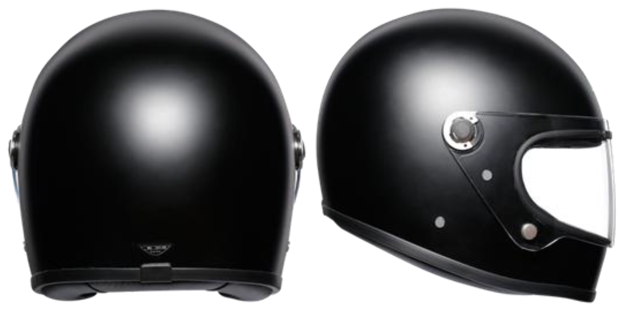
Figure 2.
Frequency response of the PUI Audio AOM-5024L-HD-R capsule.
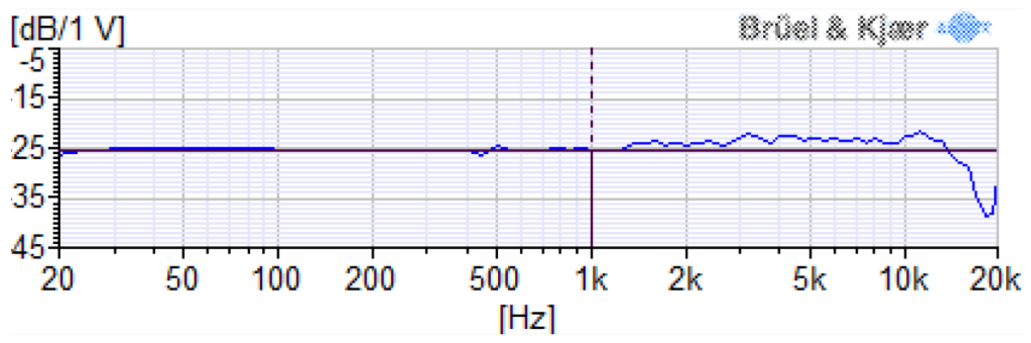
Figure 3.
Side view of the array helmet after assembling the capsules (left). A view of the array helmet mounted on the two-axis turntable during the acoustic characterization (right).
Figure 3.
Side view of the array helmet after assembling the capsules (left). A view of the array helmet mounted on the two-axis turntable during the acoustic characterization (right).
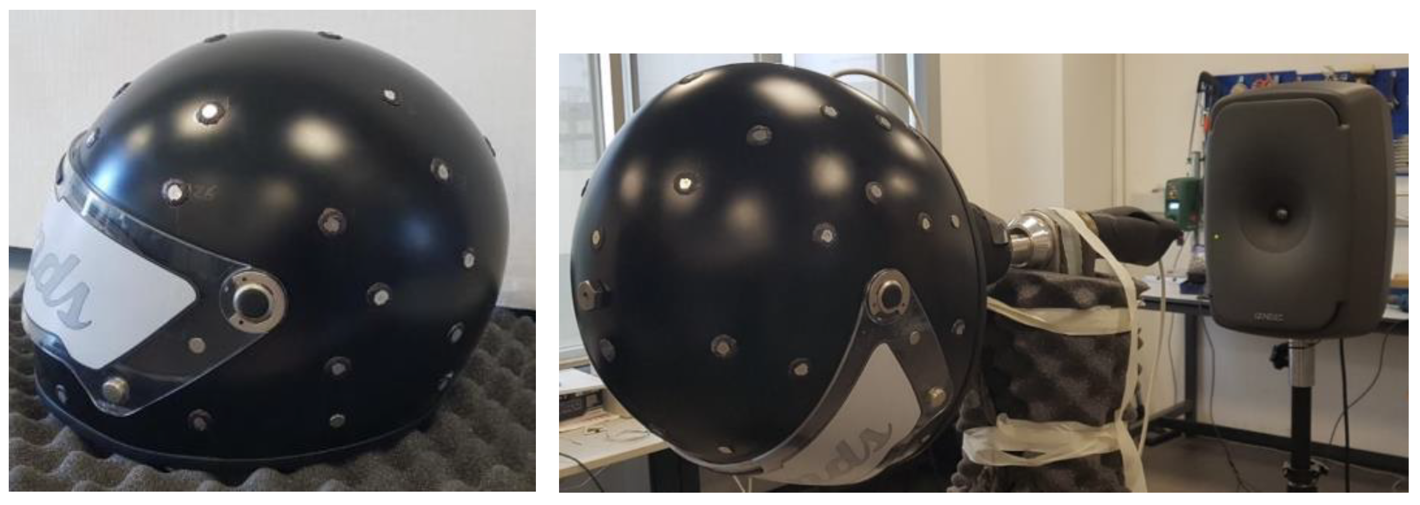
Figure 4.
Ideal 3D directivity of the first v = 16 Spherical Harmonics (Ambisonics 3rd order).
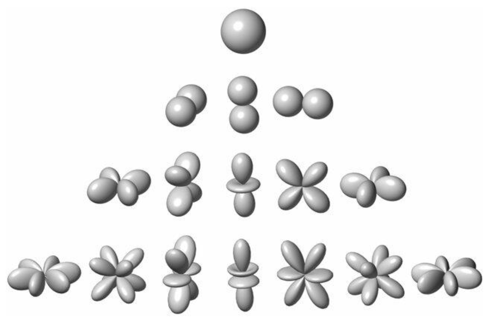
Figure 5.
Block scheme of entire system.
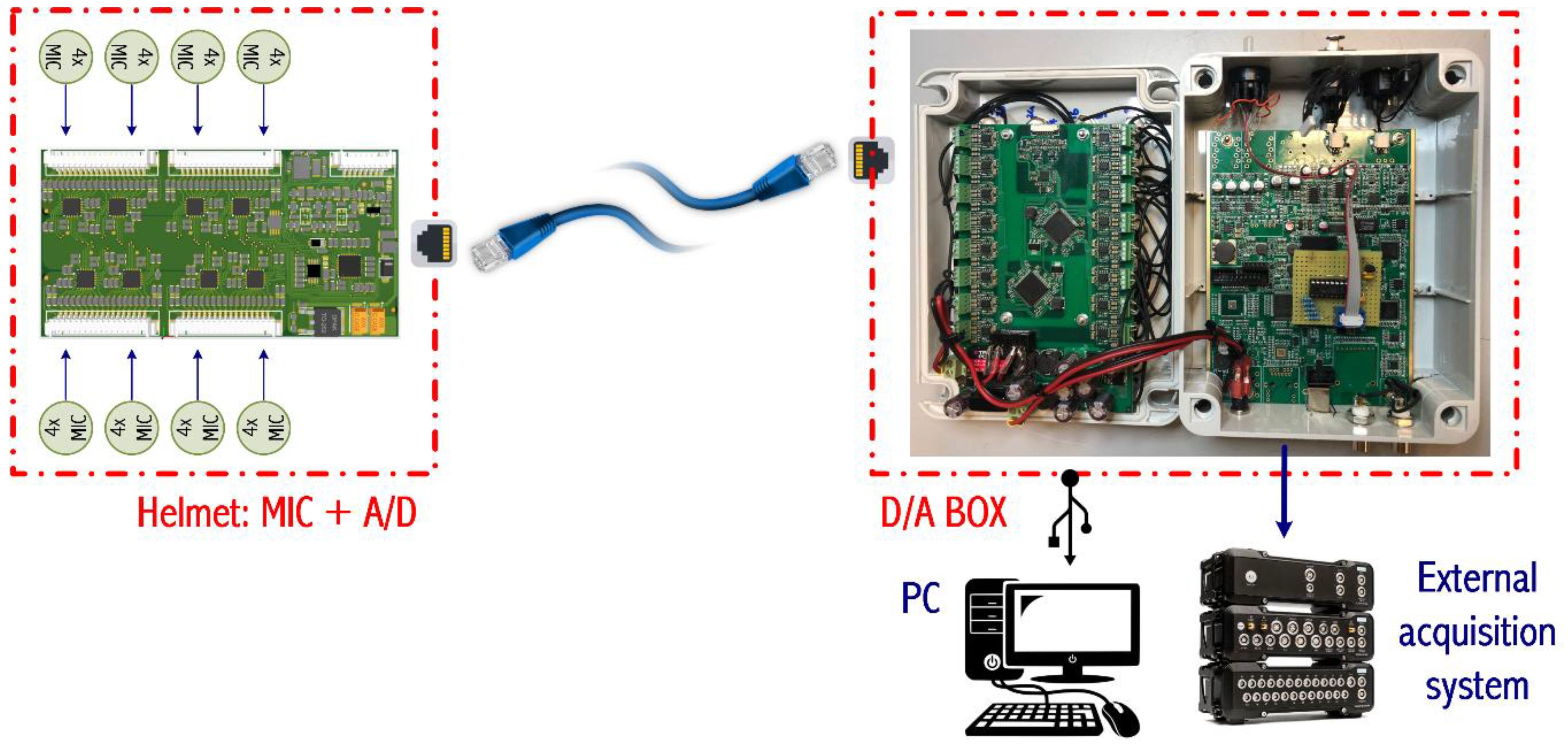
Figure 6.
Block scheme of the A/D board installed inside the helmet (right). Ethernet socket on the helmet (left).
Figure 6.
Block scheme of the A/D board installed inside the helmet (right). Ethernet socket on the helmet (left).
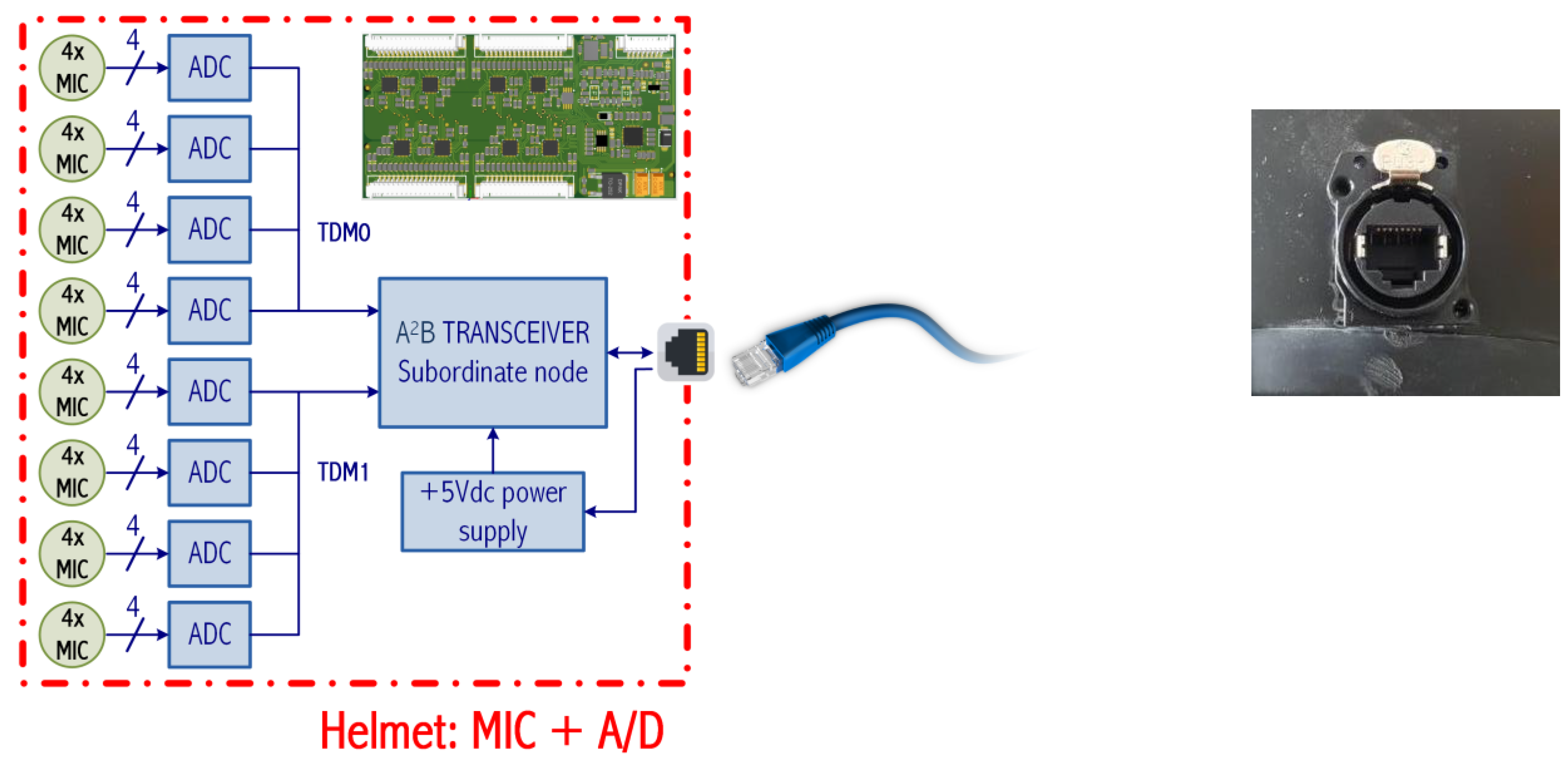
Figure 7.
Block scheme of D/A box.
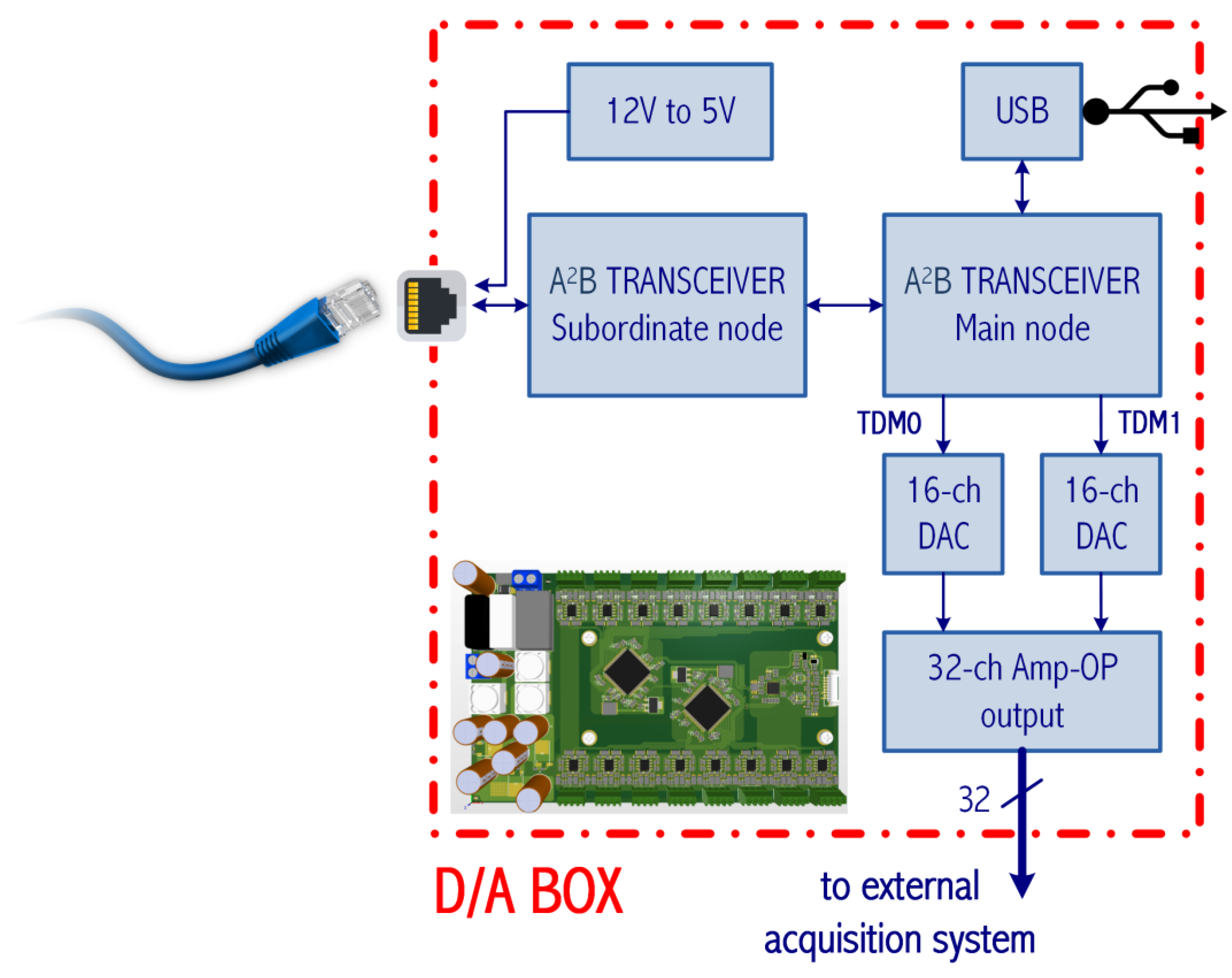
Figure 8.
The prototype of D/A box: a view from above of the 32 BNC connectors (left), the A2B subordinate node (center) and the A2B main board (right).
Figure 8.
The prototype of D/A box: a view from above of the 32 BNC connectors (left), the A2B subordinate node (center) and the A2B main board (right).
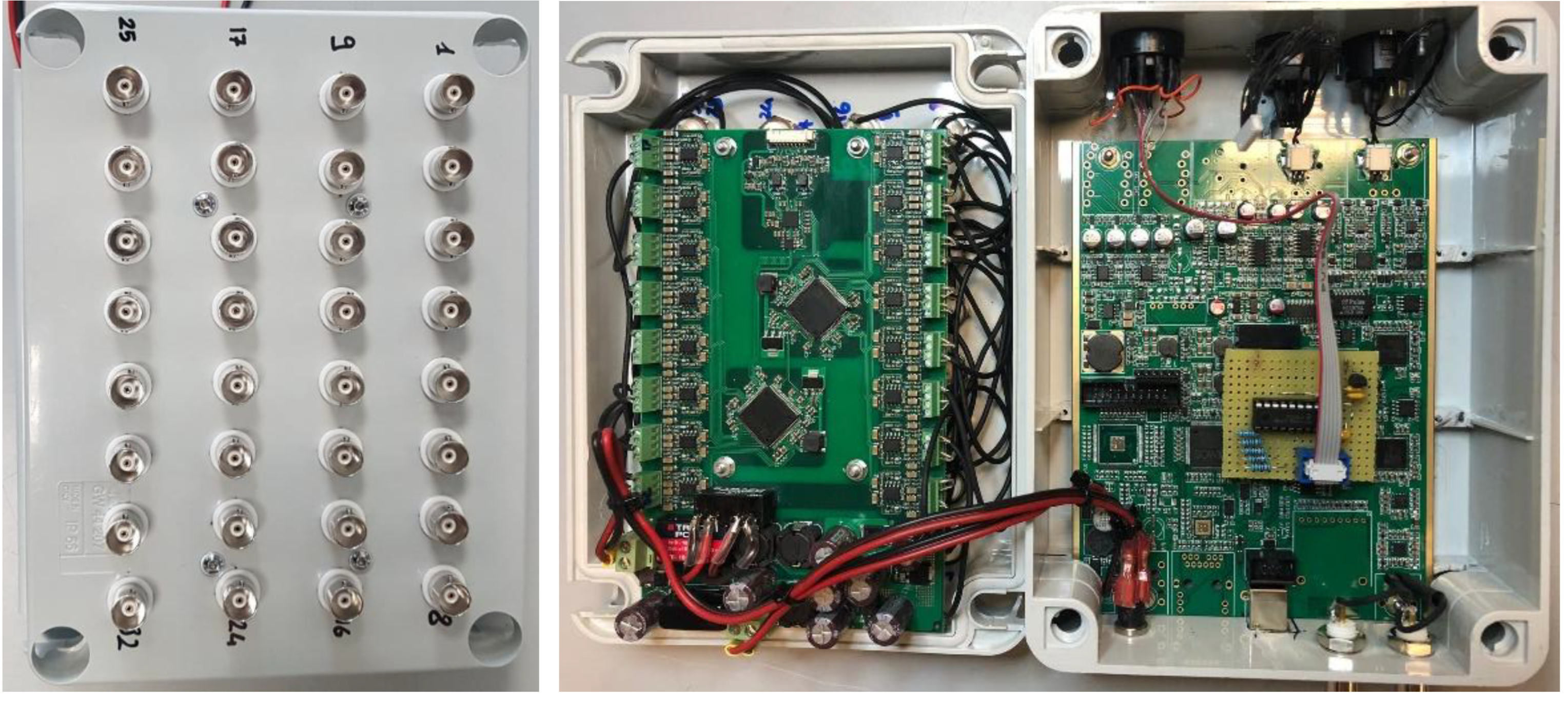
Figure 9.
SC (left) and LD (right) calculated for the Eigenmike32.
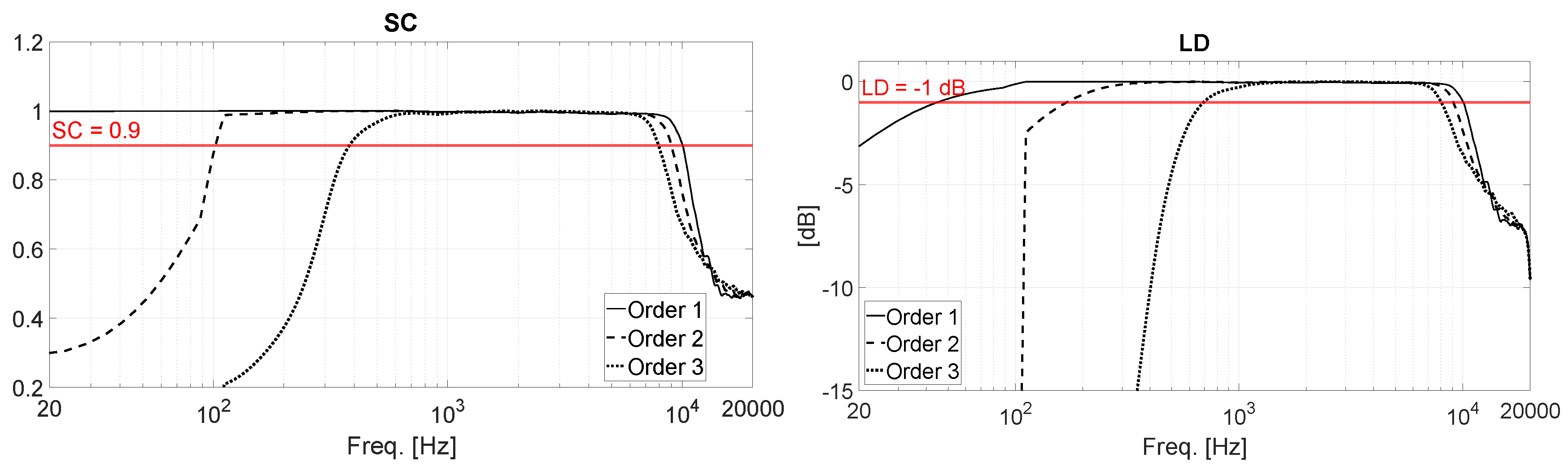
Figure 10.
SC (left) and LD (right) calculated for the array helmet.
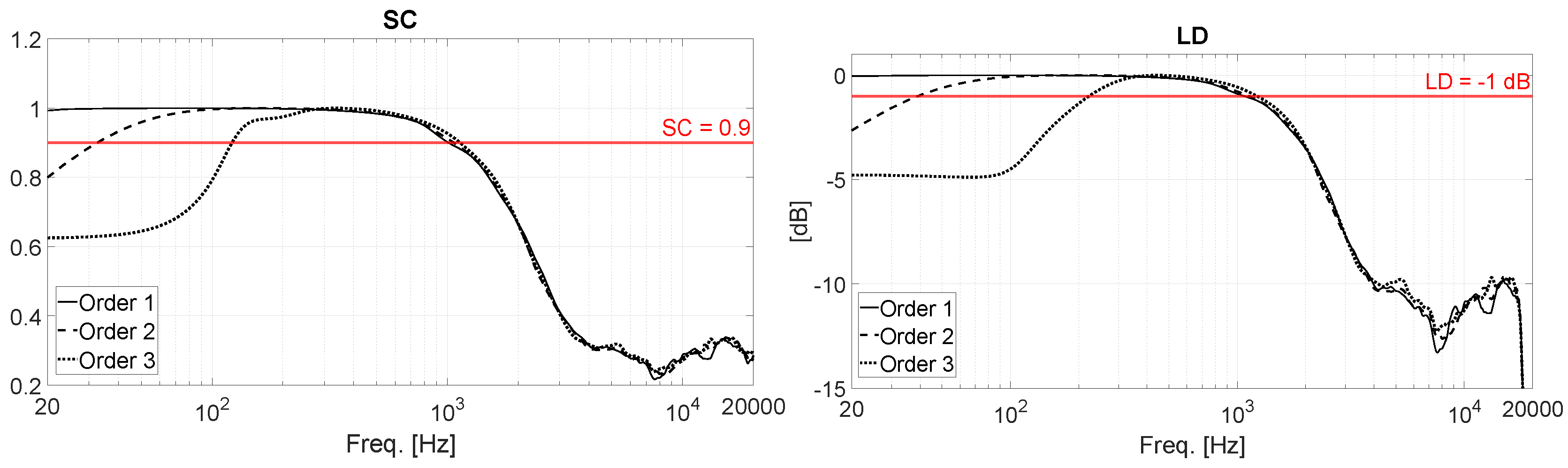
Figure 11.
Sound color map analysis of a pink noise source located in (0° ; 0°) at various octave bands.
Figure 11.
Sound color map analysis of a pink noise source located in (0° ; 0°) at various octave bands.
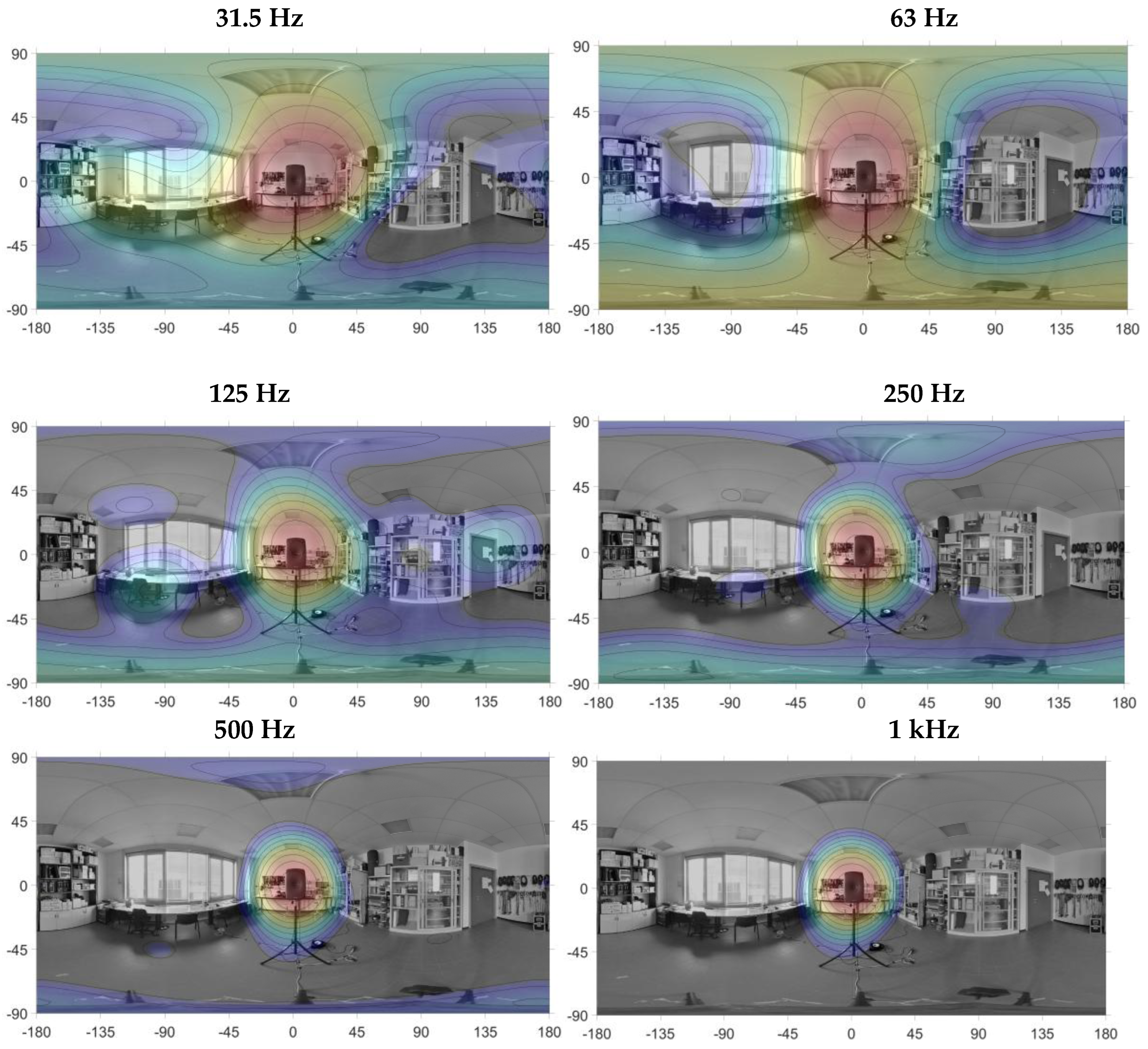

Table 1.
Microphonic capsule specification (AOM-5024L-HD-R).
| Characteristic | Value |
|---|---|
| Diameter | 9.7 mm |
| Height | 5 mm |
| Type | Analogue, electret |
| Directivity | Omnidirectional |
| Freq. range | 20 Hz - >10 kHz |
| Self-noise | 14 dB(A) |
| Max SPL | 110 dB |
Table 2.
A/D converter specification (TLV320ADC6140).
| Characteristics | Value |
|---|---|
| Number and type of input channels | 4-channels, analog |
| Dynamic range | 123 dB |
| Total harmonic distortion + noise (THD+N) | -98 dB |
| Input voltage range | 2 Vrms |
| Sample rate | 8 to 768 kHz |
| Power consumption | 9.2 mW/ch @ 48 kHz |
| Audio serial data interface | TDM or I2S |
Table 3.
D/A converter specification (ADAU1966).
| Characteristics | Value |
|---|---|
| Number of output channels | 16-channels, single ended |
| Resolution | 24 bits |
| Dynamic range | 110 dB(A) |
| Total harmonic distortion + noise (THD+N) | -97 dB |
| Sample rate | 32 to 192 kHz |
Table 4.
Frequency limits at various Ambisonics orders.
| Ambisonics order | Eigenmike32 | Array helmet | ||
|---|---|---|---|---|
| Min. Freq. [Hz] | Max. Freq. [Hz] | Min. Freq. [Hz] | Max. Freq. [Hz] | |
| 1 | 45 | 10000 | 20 | 1000 |
| 2 | 170 | 9000 | 40 | 1000 |
| 3 | 700 | 7900 | 220 | 1000 |
Table 5.
Ambisonics orders at different octave bands.
| Octave bands [Hz] | Ambisonics order | |
|---|---|---|
| Eigenmike32 | Array helmet | |
| 31.5 | - | 1 |
| 63 | 1 | 2 |
| 125 | 1 | 2 |
| 250 | 2 | 3 |
| 500 | 2 | 3 |
| 1000 | 3 | 3 |
Disclaimer/Publisher’s Note: The statements, opinions and data contained in all publications are solely those of the individual author(s) and contributor(s) and not of MDPI and/or the editor(s). MDPI and/or the editor(s) disclaim responsibility for any injury to people or property resulting from any ideas, methods, instructions or products referred to in the content. |
© 2025 by the authors. Licensee MDPI, Basel, Switzerland. This article is an open access article distributed under the terms and conditions of the Creative Commons Attribution (CC BY) license (http://creativecommons.org/licenses/by/4.0/).
Copyright: This open access article is published under a Creative Commons CC BY 4.0 license, which permit the free download, distribution, and reuse, provided that the author and preprint are cited in any reuse.


