2. A Three-Dimensional Dynamic Trajectory Planning Framework Based on PPO and IIFDS
To simplify the analysis in this paper, the following assumptions are made:
Assumption 1: All obstacles, including both static and dynamic obstacles, are approximated as standard convex polyhedrons, such as spheres, ellipsoids, and cylindrical shapes. The mathematical representation of an obstacle’s boundary can be defined as:
(1)
where represents an implicit expression for the boundary of an obstacle. A value of indicates that point lies exactly on the obstacle's surface, a value less than indicates that is inside the obstacle, and a value greater than indicates that is outside the obstacle. are the coordinates of point, while denote the coordinates of the obstacle's center in the three-dimensional space. control the extent of the obstacle along the ,,and directions (i.e., the size of the obstacle). control the curvature of the obstacle along each direction (i.e., the exponents of the shape parameters).
Assumption 2: The information on the target location and obstacle status at the current moment is available online. This information includes, but is not limited to, position and velocity.
2.1. Introduction to the Improved Interfered Fluid Dynamical System (IIFDS)
2.1.1. Initial Flow Field Velocity Model
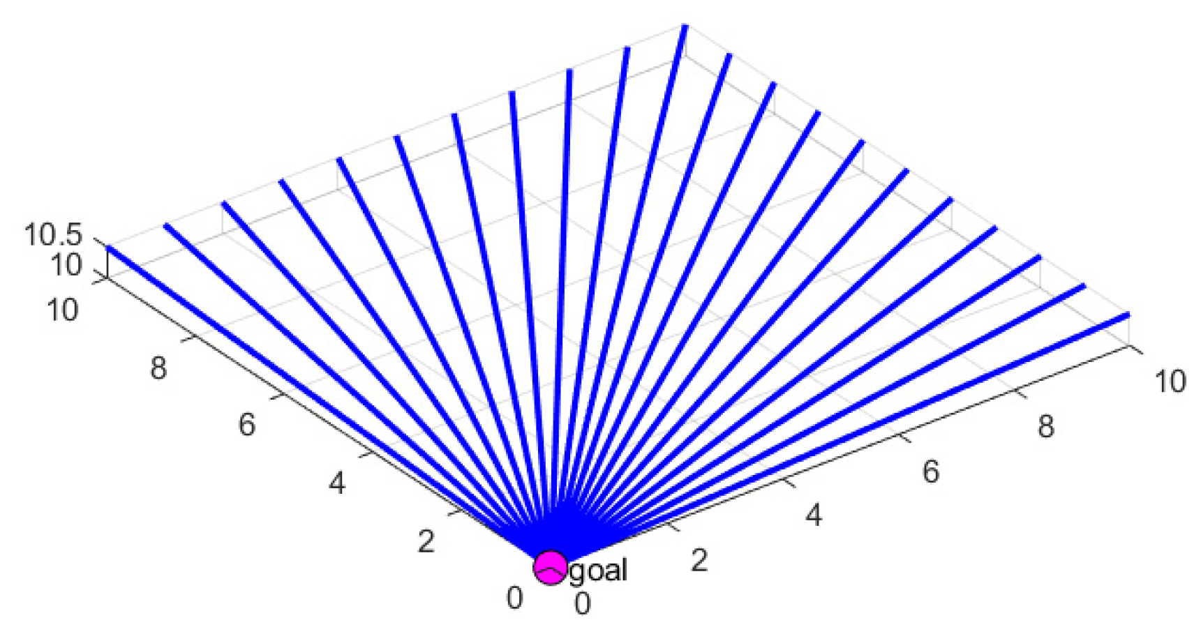
The IIFDS algorithm is based on mimicking the characteristics of natural fluid dynamics. Under conditions free from interference, the initial flow field streamlines are directed straight toward the target point. The model of the initial flow field is shown in
Figure 1.
In the initial flow field, the velocity vector of the fluid passing through each position , denoted as , can be expressed as:
(2)
where represents the velocity vector of the initial flow field at the current position of the AUV. is a virtual velocity constant, used to determine the intensity of the flow field. denotes the current position of the AUV, represents the target position, and denotes the Euclidean distance between the current position and the target point , which is given by:
(3)
2.1.2. Obstacle Influence Modeling
When obstacles exist in the environment, their influence on the predefined initial flow field changes the fluid's velocity direction, resulting in flow field distortion. The effect of obstacles on the initial flow field is modeled using an influence matrix, defined as:
. (4)
where represents the overall disturbance matrix, denotes the weight coefficient of the k-th obstacle, is the disturbance matrix of the k-th obstacle, and indicates the total number of obstacles.
The weight coefficient for each obstacle is defined as:
(5)
where represents the implicit equation of the obstacle's surface, defining whether is inside, on, or outside the obstacle.
The influence matrix of the k-th obstacle is defined based on repulsion and redirection effects as:
(6)
where denotes the 3×3 identity matrix, also referred to as the attraction matrix, which functions similarly to the attractive force in the artificial potential field method. represents the normal vector of the obstacle's surface, represents the tangential vector, and is the repulsion coefficient that controls the intensity of the obstacle's repulsive effect. A larger value enables the disturbed fluid to avoid obstacles in the environment earlier. denotes the tangential response coefficient, which regulates the intensity of tangential fluid flow. represents the distance from the obstacle's center to the current position, normalized by the obstacle's radius.
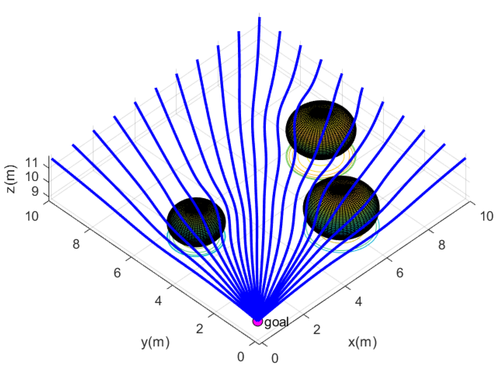
In a three-dimensional environment with obstacles, the presence of obstacles causes deviations in the original flow field paths, resulting in a disturbed flow field. This disturbed flow field is capable of avoiding obstacles while converging toward the target point. The disturbed flow field model is illustrated in
Figure 2.
2.1.3. Tangential Vector Modeling
In the practical application of the IIFDS algorithm, the flow lines generated for obstacle avoidance are often restricted to a single plane, which may result in trajectories becoming trapped in local minima or stagnating at certain points. To address this issue, the IIFDS algorithm introduces the concept of a tangential matrix, allowing flow lines to move in arbitrary directions around obstacles rather than being confined to a single plane. When approaching stagnation points, the IIFDS algorithm enhances the tangential matrix to provide tangential momentum along the obstacle surface, effectively preventing the AUV from lingering at stagnation points.
On the tangent plane defined by the normal vector , any tangential vector is generated as follows:
(7)
where represents the tangential vector in the local tangential coordinate system, determined based on the tangential angle . denotes the rotation matrix that transforms the local tangential basis vectors into the global coordinate system, defined as:
(8)
In this context, controls the rotational angle of the tangential direction, determining the specific direction for bypassing the obstacle.
2.1.4. Influence of Dynamic Obstacles
The velocity of dynamic obstacles affects the flow field through the following equation:
(9)
where represents the velocity influence of the dynamic obstacle at the current position. denotes the normalized distance between the current point and the obstacle. is the attenuation factor, which controls the influence range of the obstacle's velocity on the flow field. represents the velocity vector of the dynamic obstacle.
2.1.5. Comprehensive Velocity Calculation
The comprehensive velocity of the AUV is calculated using the following equation:
(10)
2.1.6. Trajectory Update
The next trajectory point is determined by integrating the velocity , according to the following equation:
(11)
where is the time step.
2.1.7. Heading and Pitch Angle Constraints
From the above derivation, it can be seen that traditional IIFDS does not explicitly consider the motion model and constraints of the AUV during trajectory planning. In 3D dynamic trajectory planning for AUVs, to ensure that the generated trajectory satisfies both the optimization objectives of flow-field perturbation and the motion capability constraints of the AUV itself, we introduce dynamics and kinematics constraints. These constraints primarily act on the updates of the heading angle and pitch angle, and by adjusting the next position, they ensure the physical feasibility of the trajectory.
Based on the current position of the AUV, , the position at the previous time step, , and the next position predicted by the flow field, , the heading angle and its variation are calculated as follows:
(12)
where denotes the heading angle from to , and represents the heading angle from to .
If , the heading angle is corrected as follows:
(13)
The correction logic for the pitch angle is analogous to that of the heading angle and is not repeated here. After completing the corrections for the heading and pitch angles, the previously planned position for the next time step is updated accordingly. The corrected position is given by:
(14)
where represents the next position of the AUV after incorporating the dynamics and kinematics constraints, and denotes the corrected pitch angle.
2.2. Introduction to the Improved PPO Algorithm
From Equation (6), it can be seen that the influence matrix is not only related to the position of the AUV and the implicit equation of the obstacle's surface but also to the repulsion coefficient ,tangential response coefficient , and directional coefficient of each obstacle. If these three parameters are fixed, the resulting trajectory may fail to meet the specific requirements of certain scenarios or obstacles, leading to suboptimal trajectory planning.
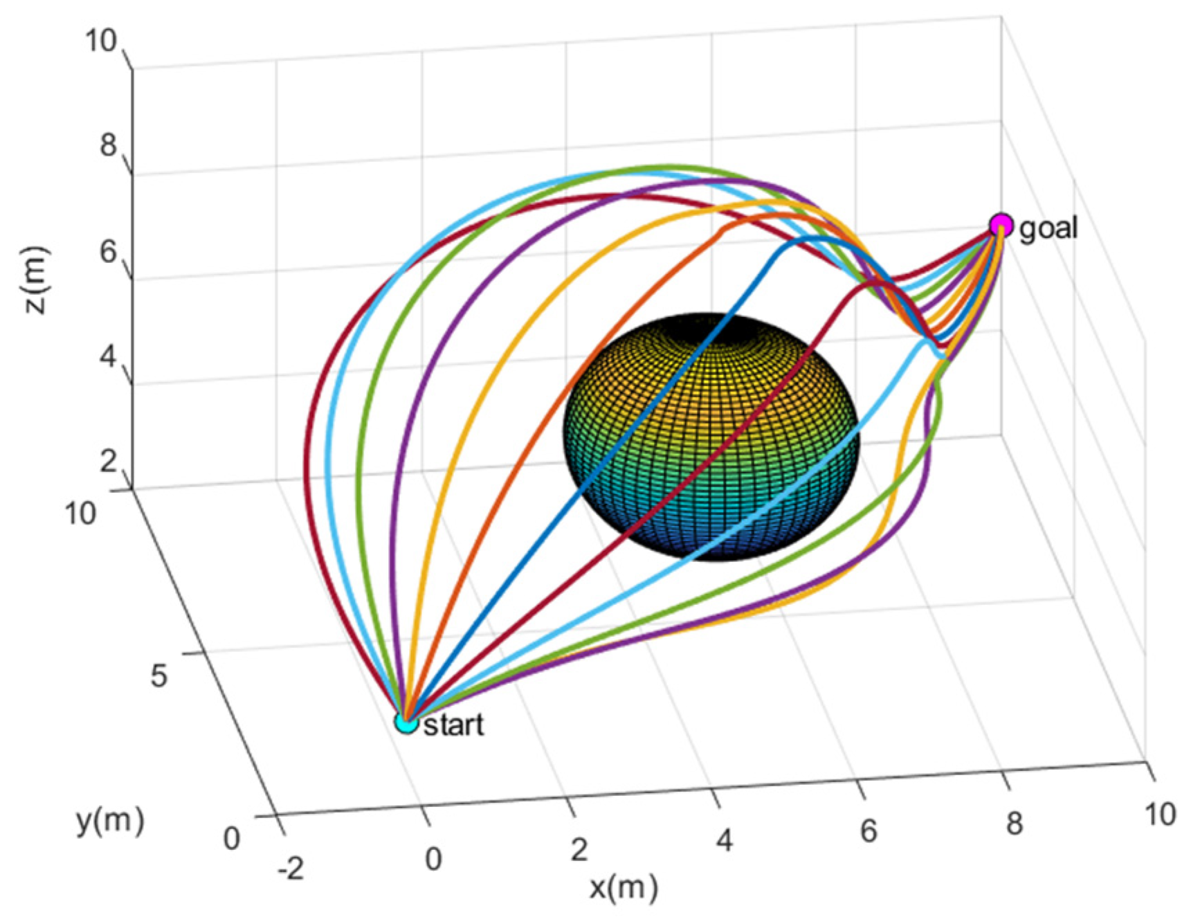
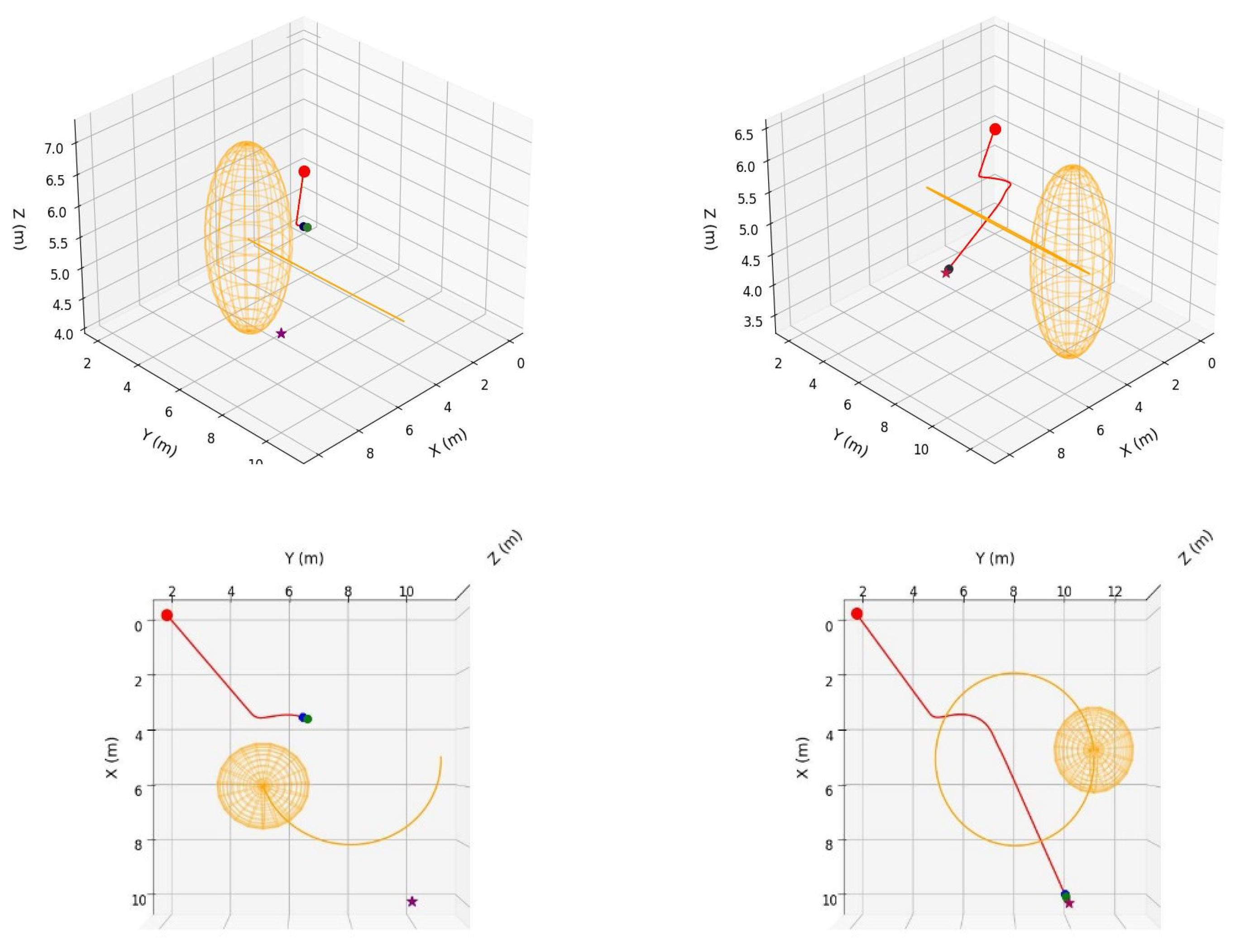
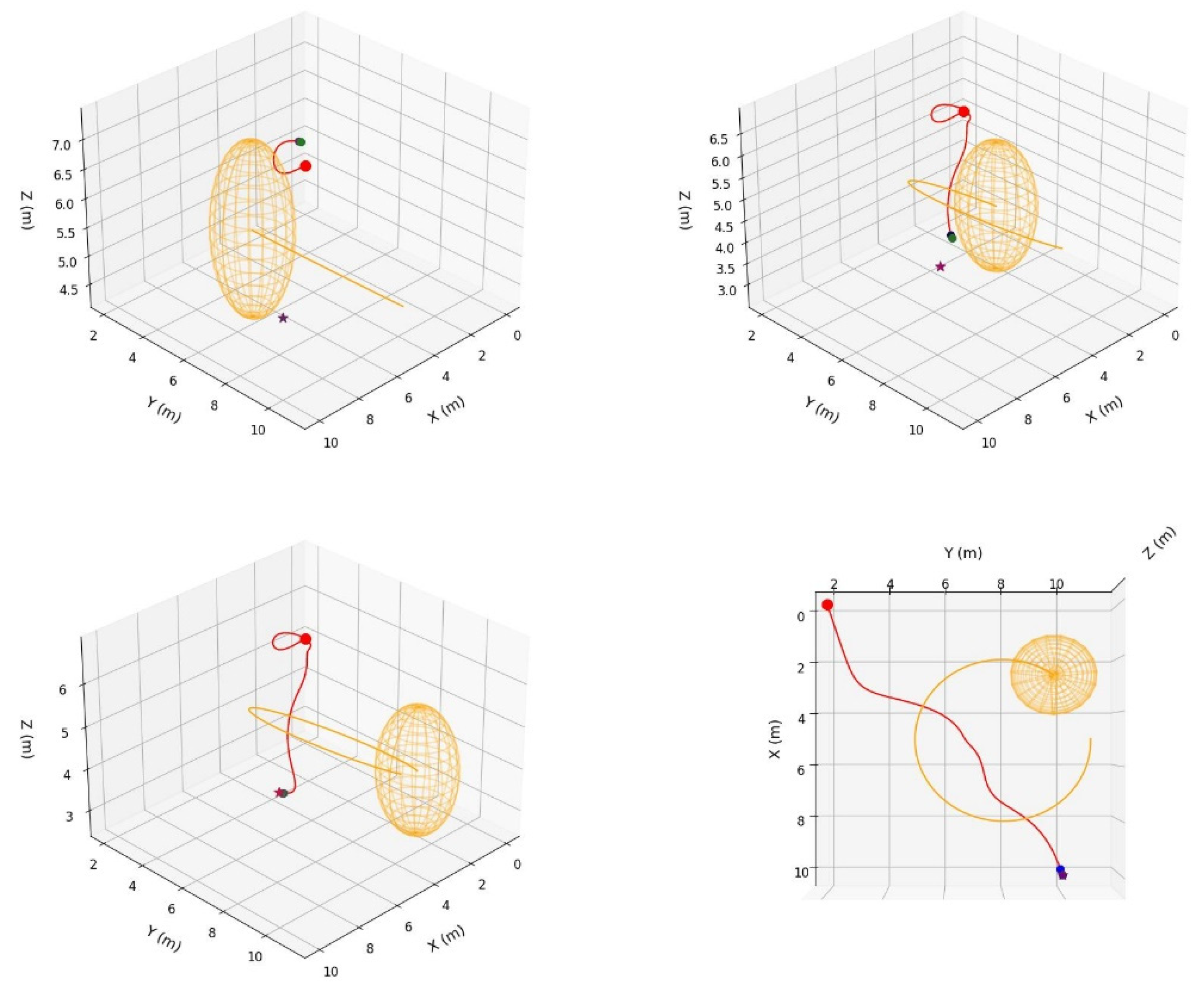
As shown in
Figure 3, the plotted trajectories represent different parameter combinations. The orange trajectory in the bottom-right corner corresponds to
,
, and
,From the bottom-left to the top-left corner, the coefficients increment by 0.2 for each trajectory. Different parameter combinations determine the shape and direction of the trajectories. In previous research [
20], receding horizon control (RHC) has been used to optimize these parameters online. However, the serial nature of RHC's solution mechanism is not well-suited to the robustness and real-time requirements of complex dynamic obstacle environments.
PPO is a policy-based deep reinforcement learning algorithm and an off-policy algorithm. With its advantages of high stability and strong real-time performance in complex dynamic environments, we choose the PPO algorithm to optimize the three parameters of the IIFDS algorithm: the repulsion coefficient , the tangential coefficient , and the directional coefficient . The PPO algorithm comprises five core components: environment, agent, state, reward function, and action. The following sections will provide detailed explanations of these five components.
In the 3D dynamic trajectory planning task, the environment is a three-dimensional space that contains multiple dynamic spherical obstacles with varying radii and trajectories. In this environment, it is possible to observe the instantaneous velocities of the dynamic obstacles at any given moment, the distance between the AUV and the surface of the obstacles, as well as the relative position of the AUV to the target point. This dynamic environment simulates various complex scenarios that the AUV might encounter during real-world navigation, providing a realistic basis for testing and validating the algorithm.
In the 3D dynamic trajectory planning task, the AUV is considered as the agent.
The state space represents the collection of environmental information perceived by the agent. It comprises three vectors: the vector pointing to the target point, the vector pointing to the surface of the nearest obstacle, and the velocity vector of the nearest obstacle.
In traditional deep reinforcement learning methods, the reward function in the PPO algorithm often suffers from the issue of sparse rewards, which makes the learning process less adaptive to specific tasks. This issue is particularly pronounced in the 3D dynamic trajectory planning task for AUVs, where traditional reward designs fail to effectively guide the AUV in performing fine-grained action control. To address this, the paper introduces an improved reward function aimed at providing more precise guidance for the dynamic trajectory planning of the AUV. This reward function comprises five main components: obstacle avoidance reward, target distance reward, trajectory smoothness reward, dynamics constraint reward, and energy consumption reward.
(1) Obstacle Avoidance Reward
The obstacle avoidance reward encourages the AUV to maintain a safe distance from obstacles while considering the velocity of the obstacles. The reward is calculated as follows:
(15)
where, represents the dynamic influence factor of the obstacle’s velocity on the reward. Faster obstacle velocities increase the dynamic impact factor, which amplifies the reward’s sensitivity to obstacle avoidance. is the distance between the AUV and the center of the obstacle. is the radius of the obstacle. is the threshold radius of the obstacle’s influence zone. is the velocity vector of the obstacle.
(2) Target Distance Reward
The target distance reward encourages the AUV to move closer to the target point, with the reward increasing as it approaches the target. The reward is calculated as follows:
(16)
where, represents the distance between the current position of the AUV and the target point. represents the total distance from the starting point to the target point.
is a small positive constant added to prevent logarithmic computation errors.
If the AUV is very close to the target (less than a specified threshold value), an additional bonus reward is given:
(17)
(3) Trajectory Smoothness Reward
The trajectory smoothness reward is designed to encourage the AUV to move along a smooth trajectory, avoiding abrupt changes in direction, velocity, or acceleration. The reward is defined as follows:
(18)
where, represents the angle between the current motion direction of the AUV and the direction toward the target. denotes the change in velocity between the current and previous time steps. represents the current acceleration of the AUV.and are weighting factors penalizing changes in velocity and acceleration, respectively.
(4) Kinematic Constraint Reward
The kinematic constraint reward ensures that the AUV's motion adheres to kinematic limits, avoiding excessive heading angles, pitch angles, and over-speeding behaviors. The reward is defined as:
(19)
where, represent the AUV's current heading and pitch angles. , represent the corrected heading and pitch angles. , denote the maximum allowable variations in heading and pitch angles. represents the current speed of the AUV, and represents the current acceleration of the AUV. , denote the maximum allowable speed and acceleration of the AUV. and are weighting factors penalizing excessive speed and acceleration, respectively.
(5) Energy Consumption Reward
This reward penalizes energy-inefficient behaviors and encourages the AUV to adopt energy-saving motion strategies. It is defined as:
(20)
where, represents the current speed of the AUV. is the weighting factor for the energy consumption penalty.
(6) Total Reward Function
By combining all the individual reward components, the total reward function is obtained, which comprehensively guides the AUV to accomplish its tasks while ensuring stable, safe, and efficient motion. The total reward is expressed as:
(21)
The trajectories generated by the IIFDS algorithm are determined by three parameters within the algorithm: the repulsion coefficient , the tangential coefficient , and the directional coefficient . Therefore, we select these three parameters as the action outputs of the improved PPO algorithm.
2.3. Optimization of IIFDS Parameters Using the Improved PPO
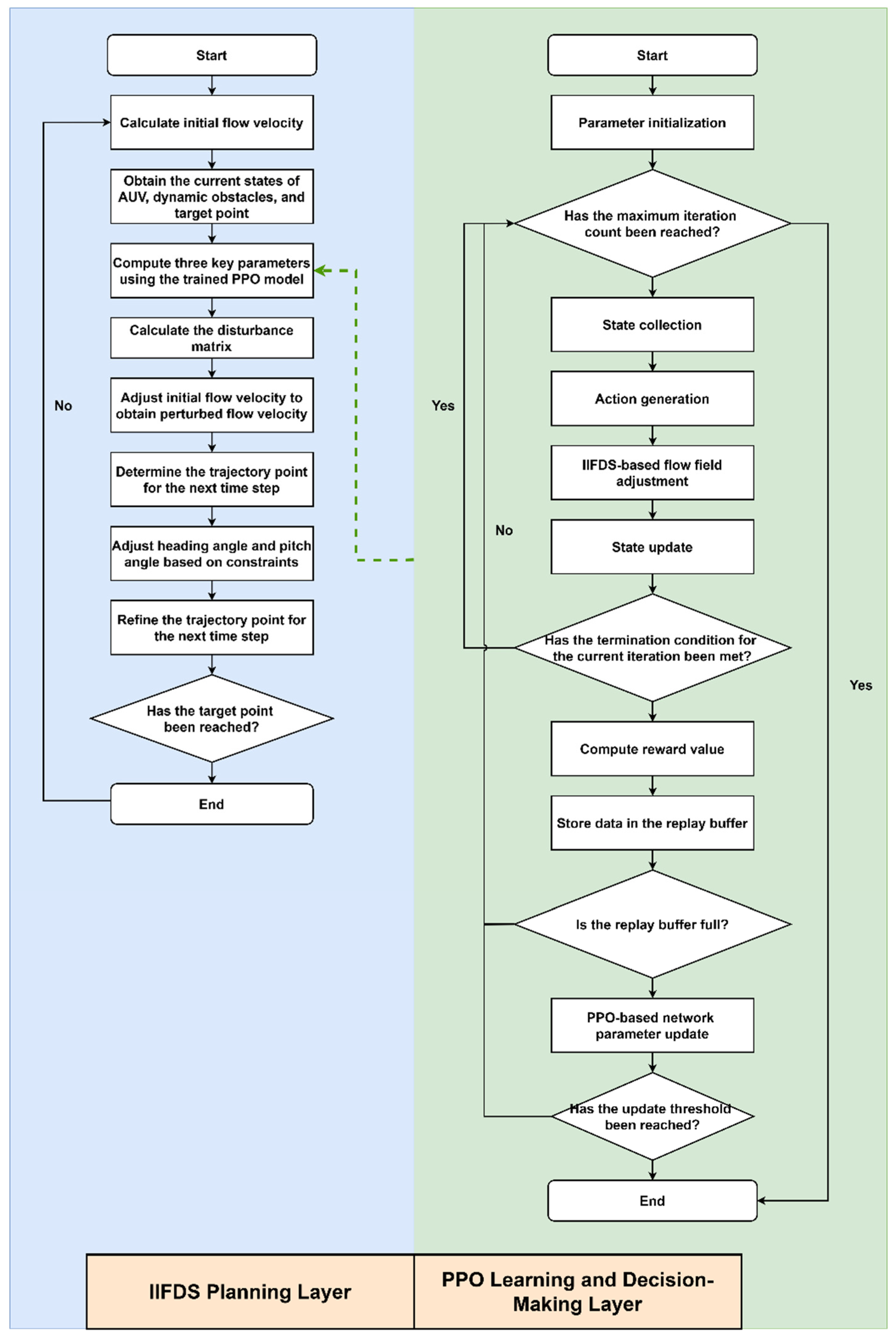
To enable trajectory planning for AUVs in complex dynamic three-dimensional environments, this paper proposes a trajectory planning framework based on the integration of PPO and IIFDS. In this framework, IIFDS serves as the planning layer, adjusting the flow field parameters dynamically to generate trajectories that adapt to moving obstacles. PPO acts as the learning and decision-making layer, optimizing the IIFDS flow field parameters, including the repulsion coefficient
, the tangential coefficient
, and the directional coefficient
. The detailed process of the integrated algorithm is shown in the flowchart in
Figure 4.
Initialization involves setting the IIFDS flow field parameters, constructing the AUV dynamics model and dynamic obstacle environment, and defining the start and target points. Simultaneously, the Actor-Critic network of the PPO algorithm is initialized, along with the replay buffer (size 4096). Multi-objective reward functions and related hyperparameters (discount factor, PPO clipping range, learning rate, etc.) are also configured.
Subsequently, the training loop is entered, which primarily includes the main loop and the PPO network update component.
The main loop constitutes the core part of the interaction between the AUV and the environment during training. The detailed steps of the main loop are as follows:
Step 1: State Collection
The AUV gathers environmental information through sensors to construct the current state, including the vector pointing to the target, , and the vector pointing to the surface of the nearest obstacle, , as well as the velocity vector of the nearest obstacle, . The current state vector is represented as:
(22)
Step 2: Action Generation
The action for the current state is generated through the Actor network of the PPO algorithm. First, the Actor network produces the parameters of a Gaussian distribution:
(23)
where represents the mean vector of the actions, and represents the standard deviation vector of the actions.
Subsequently, actions are sampled from the Gaussian distribution:
(24)
Step 3: Flow Field Adjustment and Trajectory Planning
The planning layer of the IIFDS algorithm adjusts the flow field dynamically based on the action . The repulsion intensity of the obstacle is modified through , the tangential effect range is adjusted through , and the flow field direction is altered via , enabling the AUV to avoid obstacles. The next trajectory point is planned using the following formula:
(25)
Subsequently, the AUV state is updated:
(26)
Step 4: Reward Calculation
Based on the current state , action , and the next state , the instantaneous reward is calculated as:
(27)
Step 5: Data Storage
The current state, action, reward, and next state are stored in the experience replay buffer:
(28)
Step 6: Termination Check for the Main Loop
The main loop ends when any of the following termination conditions are met: The AUV reaches the target point. The AUV collides with an obstacle. The number of steps executed by the AUV reaches the predefined maximum value.
If none of the termination conditions are met, the process continues from Step 1 to execute the next step. If the termination conditions are met, the current episode ends, and a new episode begins by reinitializing the environment (including start point, target point, and obstacle information). Once the experience replay buffer is full (set to a capacity of 4096 in this study), it triggers an update of the PPO network.
First, the Critic network parameters are optimized using the mean square error loss function:
(29)
where represents the instantaneous reward, represents the value function of the current state, and is the discount factor.
Next, the Actor network parameters are optimized using the objective function of PPO, which includes a clipping mechanism:
(30)
where represents the advantage function, balancing the action preference.
The training loop continues until the termination condition is met. The termination condition for the training loop is defined as follows: the variation in parameters of the PPO's Actor and Critic networks falls below the predefined threshold, and the training iteration reaches the preset value.
During the testing process, the initial velocity of the AUV is first calculated, and based on the current state information, the pre-trained Actor network of PPO generates the updated IIFDS flow field parameters. Next, through optimized computation, the disturbance matrix is determined, and the velocity of the initial flow field is corrected to obtain the resultant velocity, which determines the trajectory point at the next time step. Then, based on the dynamics and kinematics constraints, this trajectory point is further corrected to obtain the final adjusted trajectory point at the next time step. Finally, it is evaluated whether the adjusted trajectory point reaches the target location. If not, the loop continues.The above testing loop concludes when the target is reached, marking the end of the testing process.