Submitted:
23 January 2025
Posted:
24 January 2025
You are already at the latest version
Abstract
The heat recovery system for a shaft powered aircraft gas turbine engine, comprise of a heat exchanger, working fluid, conduits for fluid flow, turbo-expander, helical heating coil, condenser, pump, electronic sensors with controllers, and a shaft powered gas turbine engine. The shaft powered aircraft gas turbine engine has a specially designed heat exchanger installed in the annulus of the engine’s exhaust system. The working fluid passing from the tubes of heat exchanger recovers heat from the exhaust gas. The recovered heat vaporizes the working fluid which drives a turbo-expander. The mechanical work developed by the turbo-expander can be used for driving the propulsion system, compressor or an electric generator. The thermal energy available after expansion work can be used to heat the inlet air into the engine to prevent ice ingestion during icing conditions. This system might increase performance and life of the engine, and reduce emissions, heat released to the environment, fuel consumption and fuel cost.
Keywords:
Heat recovery
; Shaft powered air-breathing aircraft gas turbine engines
; Environmentally Responsible Aviation
; Turbo-prop engines
; Turbo-shaft engines
; Ice ingestion
; Fuel efficiency
I. Introduction
In low speed aircrafts (shaft-powered), which include cargo aircrafts, few civil aviation aircrafts, fixed-wing and rotary-wing aircrafts (private and military), the engine supplies power to various aircraft utility systems. These aircraft utility systems comprise of Environmental Control System (ECS), pressurization system, pneumatic system, water systems, anti-ice system, and reservoir pressurization of the hydraulic system. The energy required for the functioning of these systems is extracted from the engine’s compressor [1] or by powering an electric generator through exhaust shaft power. Air-conditioning is the second most power consuming process after propulsion, on the aircraft. Therefore, to attain its targeted propulsion output the engine has to function more for the extra energy it expends other than propulsion. The energy dependency of above mentioned aircraft utility systems on the engine causes engine to wear out by reduced performance and life of engine, and increases fuel consumption, rotor speed, exhaust gas temperature. Also, the increase in fuel consumption increases the fuel cost and emissions, which affects the entity owning these aircraft. These above challenges are faced by the aviation industry today and finding a solution is very imperative. Therefore, these challenges are a motivation for this work. The goal of this work lies within the ambit of Environmentally Responsible Aviation (ERA) [2].
A shaft powered aircraft gas turbine engine is an aircraft gas turbine engine which generates thrust by shaft rotation, rotation of propellers or rotation of rotors. Therefore, turbo-prop engines and turbo-shaft engines, both are classified in the family of shaft powered aircraft gas turbine engines [3]. The two main flow configurations of these engines are direct drive engines [4] and reverse flow engines (widely used at present) [5]. This work in general is related to the recovery of heat from the exhaust gas of the shaft powered aircraft gas turbine engines. Combustion of fuel being an exothermic process generates high energy and high temperature flow of product gases. This high temperature and pressure flow enters the exhaust turbine where it expands to the exhaust pressure. This expansion process produces shaft work output. The shaft powered aircraft gas turbine engines produce maximum of its propulsive force for flight from the propellers or rotors rather than the thrust from exhaust gas [6]. The velocity of exhaust gas is very low to provide considerable thrust. Therefore, the medium-grade thermal energy of the exhaust gas can be utilized to do work output which can further be used to drive the propulsion system or aircraft utility systems (by producing electricity). This helps in reducing the fuel consumption. Less fuel consumption implies less emissions, less heat released to the environment and lower fuel cost. Additionally, the recovered thermal energy increases the engine’s performance and life. A major manufacturing and assembly advantage is that the existing systems on aircraft do not change much. This system can be installed on the existing shaft powered aircraft gas turbine engines with minor modifications. The effect of weight addition to the aircraft can be countered by reducing size of fuel tank with calculated savings in fuel, due to addition of this complete system.
II. System Construction and Working
One of the key components for heat recovery described in this work, can be called as annular finned-tube heat exchanger. Here the intention of the author is to demonstrate a heat exchanger with finned-tubes arranged inside an annulus. It should not be confused with ‘annular-finned tube heat exchanger’, in which the fins on the tubes have annular shape [7]. The annular-finned tubes when bundled together make an ‘annular-finned tube heat exchanger’. To avoid confusion in future, this component will be referred as Annular-Shaped Heat Exchanger with Finned-Tubes (ASHEFT). The illustration in Figure 1 is an isometric view of ASHEFT and Figure 2 depicts the multi-views of ASHEFT. It is to be noted that in Figure 2 the author, by purpose, ignores the hidden lines since ASHEFT has complicated construction and having hidden lines makes the views incomprehensible. This heat exchanger (ASHEFT) is designed for applications in which heat can be recovered from flow within an annulus, more details of which can be found in reference.
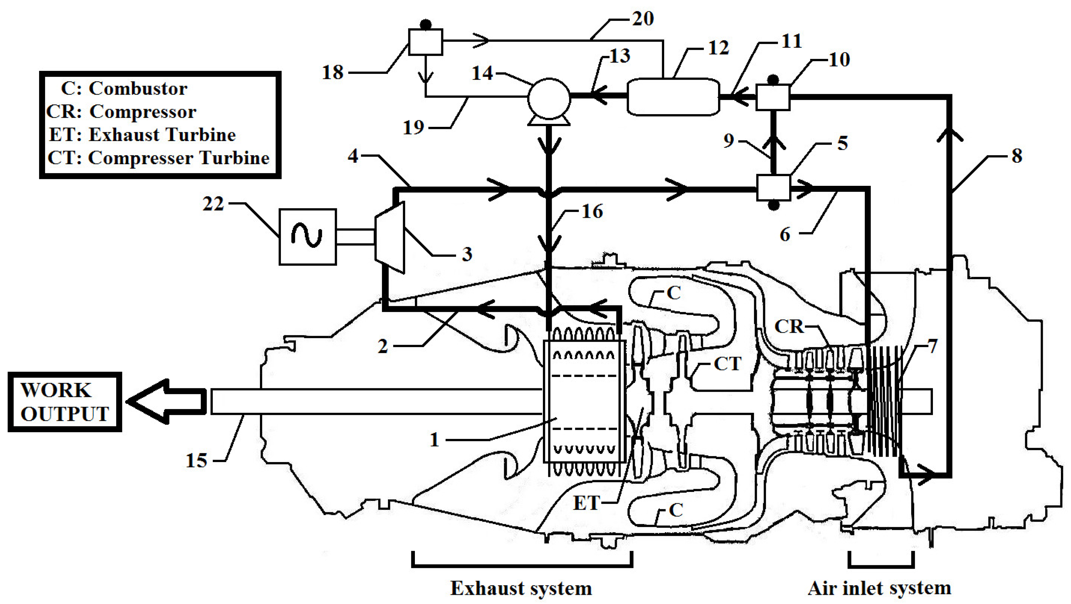
The depiction in Figure 3.a is an improved direct drive shaft powered aircraft gas turbine engine, an ASHEFT can be installed in the exhaust system. The ASHEF fits co-axially in the annulus of the exhaust system of a direct drive shaft powered aircraft gas turbine engine. The fitting can be done by welding metal brackets on the outer circumference of the ASHEFT and the inner circumference of the exhaust system or any appropriate method. The turbo-expander 3 can be mounted on exhaust shaft 15. For a direct drive shaft powered aircraft gas turbine engine, the compressor shaft and exhaust shaft are one and the same. In case of multi-spool configuration the turbo-expander 3 can be mounted on the shaft which have low-pressure system components. The exhaust shaft 15 generates required work for propulsion and Electrical Control Unit (ECU). The ASHEFT can be connected to a turbo-expander 3 by vapor flow channel 2. The orientation of the ASHEFT is very important. The ASHEFT is oriented in such a way that its tube-end with the hot working fluid leaving it, faces the exhaust turbine-side of the engine’s exhaust system, while its tube-end with cold working fluid entering it faces the exit-side of engine’s exhaust system. Such an orientation creates a cross counter flow arrangement (combination of counter flow and cross flow) between the exhaust gas and the working fluid, efficiently and effectively absorbing the thermal energy from exhaust gas to convert the working fluid into vapor. This orientation of the ASHEFT 1 is the ‘most efficient’ way of carrying out the heat recovery process. As the exhaust gas heats working fluid in the ASHEFT 1, the working fluid changes to vapor. The vapor is transferred from the ASHEFT 1 to the turbo-expander 3 by vapor flow channel 2. The vapor expands in turbo-expander 3 to generate mechanical work output. The condenser 12 can be connected to sensors 18 to provide signals through information channel 20 for the required condensing rate to achieve maximum effectiveness and efficiency based on ambient conditions like icing or non-icing, and flight conditions like engine start, take-off, cruising or landing. The hot-fluid flow channel 4 can be connected to turbo-expander 3. The flow channel 4 transfers the hot fluid from turbo-expander 3 to an icing sensor 5. When icing conditions do not prevail, an icing sensor 10 can be connected to icing sensor 5 by hot-fluid flow channel 9.
This completely sets the hot fluid flow from hot-fluid flow channel 4 towards icing sensor 10 through hot-fluid flow channel 9. Therefore, during non-icing conditions the working fluid does not flow towards hot-fluid flow channel 6. Icing sensor 10 can be connected to the condenser 12 by vapor return flow channel 11. The working fluid is transferred from icing sensor 10 to condenser 12. The condenser 12 condenses the hot working fluid received from the icing sensor 10. The condensed working fluid is transferred from condenser 12 to a pump 14 through a flow channel 13. Cold fluid flow channel 16 returns the pumped working fluid from pump 14 to the ASHEFT 1, thus completing the cycle. When icing condition prevails, flow through hot-fluid flow channel 9 between icing sensor 10 and icing sensor 5 is disconnected. Therefore, hot-fluid flow channel 9 becomes non-functional. A helical heating coil 7 is a tube/pipe coiled in a helical manner. The helical heating coil 7 can be installed in the engine’s air inlet system (within the annulus). The helical heating coil 7 can be fitted co-axially in the annulus of the engine’s air inlet system. The helical heating coil 7 is connected to icing sensor 5 by hot-fluid flow channel 6. The working fluid flow is from icing sensor 5 to helical heating coil 7. The helical heating coil 7 is oriented in such a way that its end which has hot working fluid entering it faces the compressor-side of engine’s air inlet system, while its end which has the (cold) working fluid leaving it faces the entry-side of engine (i.e., cold-outlet of the helical heating coil is closer to the engine’s entry/opening than its hot-inlet). Such an orientation creates a cross counter flow arrangement (combination of counter flow and cross flow) between the working fluid and the inlet air to engine, heating the engine’s inlet air and cooling the working fluid. This orientation of the helical heating coil 7 is the ‘most efficient and effective’ way of heating the engine’s inlet air. The helical heating coil 7 operate only during icing conditions, thus heating the inlet air to the compressor. This heating prevents the formation and ingestion of ice. It is to be noted that such kind of heating should be controlled, such that the ice ingestion is just prevented. Increasing the temperature of engine inlet air adversely affects engine performance, therefore heating engine inlet air needs to be controlled. Ice ingestion stalls the compressor, and it has adverse effects on performance and life of engine. The helical heating coil 7 plays the role of a primary condenser where the working fluid flowing through it gets cooled. Icing sensor 10 can be connected to helical heating coil 7 by working fluid flow channel 8. The working fluid flow is from helical heating coil 7 to icing sensor 10. Icing sensor 10 can be connected to the condenser 12 by vapor return flow channel 11. The rest of the operation, i.e., working fluid transfer from condenser-to-pump-to-ASHEFT, is similar to that of non-icing condition described above. In an alternative representation of direct-drive engine in Figure 3.b, the turbo-expander 3 can be installed outside engine framework. The turbo-expander 3 can be connected to an electric generator 22 to drive aircraft utility systems and other electric equipment used on the aircraft, where rest of the functioning remains same.
Additionally, another representation of the engine class described in this work is an improved reverse flow shaft powered aircraft gas turbine engine. The depiction in Figure 4.a is a reverse flow shaft powered aircraft gas turbine engine, an ASHEFT can be installed in the exhaust system. The turbo-expander 3 can be mounted on exhaust shaft 15. The functioning of this system in case of icing and non-icing conditions is similar to its functioning in the case of the icing and non-icing conditions of direct-drive shaft powered aircraft gas turbine engine, described earlier. In the first alternative representation of an improved reverse flow shaft powered aircraft gas turbine engine, depicted in Figure 4.b, the turbo-expander 3 can be mounted on the compressor shaft 45, where rest of the functioning remains same. In the second alternative representation of an improved reverse flow shaft powered aircraft gas turbine engine, depicted in Figure 5, the turbo-expander 3 can be installed outside engine framework, where rest of the functioning remains same. The turbo-expander 3 can be connected to an electric generator 22 to drive aircraft utility systems and other electric equipment used on the aircraft.
III. Working Fluid and Construction Details of Sub-Components
In Figure 3a,b, Figure 4a,b and Figure 5, the flow channel 2, 4, 6, 8, 9, 11, 13 and 16 for the transfer of working fluid, can be in the form of tube/pipe. The tube/pipe can be composed of aluminum, stainless steel, alloy steel, carbon steel, copper or any other appropriate material. The tube/pipe can have a circular cross section or a polygonal cross section. Additionally, the tube/pipe can be provided with insulation coating to prevent heat losses to the surroundings. The insulation coating for the tube/pipe can be composed of mineral wool, glass wool, flexible elastomeric foams, rigid foams, polyethylene, cellular glass, aerogel or any other appropriate material. The heat recovery system described in this work is a closed cycle. The total quantity of the working fluid in the system remains constant at all operating conditions. During the non-icing conditions, there will be non-functional working fluid inside the helical heating coil 7, flow channel 6, and flow channel 8. Therefore, the working fluid selection is a very important step and care must be taken that the freezing temperature of the working fluid is lesser than the typical temperatures at which icing occurs at different altitudes during the flight. Depending on the exhaust gas temperature and operating conditions of a shaft powered aircraft gas turbine engine, a working fluid is selected (for critical temperature and freezing point respectively). The working fluids that can be used are R245fa [8], siloxanes [9] or other suitable refrigerant. In Figure 3ab, Figure 4a,b and Figure 5, the helical heating coil 7 is a helically coiled tube/pipe for heating the engine’s inlet air during icing conditions. The cross-section of this tube can be polygonal or circular. The helical heating coil 7 may have fins. These fins can have polygonal or circular shape, and the fin thickness depends on the design. The cross section of the fins can be rectangular, triangular, convex parabolic or concave parabolic. These fins can be helically wound fins with corrugations, or continuous spirally wound fins with corrugations. The diameter of the tube/pipe, number of coils and the total length of the helical heating coil 7 depends on the design requirement.
IV. Conclusion
The system described in this work recovers the heat at the exhaust of family of shaft powered aircraft gas turbine engines. The recovered heat is converted to shaft work or electricity. This reduces fuel consumption (or has better fuel efficiency) and therefore reduces total fuel costs. It has environmental benefits like reduced emissions/heat at exhaust, hence less heat released to the environment. The effect of weight addition to the aircraft can be resolved by reducing size of fuel tank with calculated savings in fuel, due to addition of this complete system. Icing effects (ice ingestion) in engines can be successfully handled (engine icing causes air accidents). Since heat recovery causes production of useful work or electricity which powers the aircraft utility systems, the engine becomes self-sufficient partially/completely and performs aircraft propulsion more effectively and efficiently. In other words, the compressor bleed for driving the aircraft utility systems can be reduced partially or completely. This implies that there will be lower or no demand on the engine to perform operations other than propulsion, which means that engine’s life increases and its performance improves. Air conditioning operation (ECS) which accounts to be the second largest energy consumption can be performed successfully with the existing components on aircraft, which will be powered by the work/electricity developed from this system (heat recovery). So this system can be successfully installed in all aircrafts without the necessity of replacing the existing components.
Acknowledgments
I would like to thank my friends Sachin Purohit, Mohsen Tehrani, Aditya Shetty, Dr. Katherine Fu, Sarthik Shah, Pareekshith Allu, Wei Lv, Rahul Gandhi, Shafi Motiwalla, Manan Trivedi, Omkar Mane, Ratheesvar Mohan, Marcus Pereira, Sivaramakrishnan Vaidyanathan and Hitesh Chhabra, for supporting me and this project all the way.
More Information
References
- R. Tipton, R. S. Figliola, and J. M. Ochterbeck, “Thermal Optimization of the ECS on an Advanced Aircraft with an Emphasis on System Efficiency and Design Methodology,” SAE Tech. Pap., Jun. 1997. [CrossRef]
- K. L. Suder, “Overview of the NASA Environmentally Responsible Aviation Project’s propulsion technology portfolio,” 48th AIAA/ASME/SAE/ASEE Jt. Propuls. Conf. Exhib. 2012, 2012. [CrossRef]
- P. P. Walsh and P. Fletcher, Gas Turbine Performance. Wiley, 2004. [CrossRef]
- “Airframes, Engines, and Systems, Part 2, Langley Flying School.” https://www.langleyflyingschool.com/Pages/Airframes, Engines and Systems--Part 2.html (accessed Jan. 20, 2025).
- “PILATUS PC-12 Specifications, Cabin Dimensions, Performance.” https://www.globalair.com/aircraft-for-sale/specifications?specid=1062 (accessed Jan. 20, 2025).
- “Turboprop Thrust.” https://www.grc.nasa.gov/www/k-12/airplane/turbprp.html (accessed Jan. 20, 2025).
- S. S. Jagtap, “An Apparatus for Exchanging Heat with Flow in an Annulus,” J. Eng. Sci. Technol. Rev., vol. 10, no. 1, pp. 173–176, 2017, Accessed: Jan. 11, 2019. [Online]. Available: http://www.jestr.org/downloads/Volume10Issue1/fulltext241012017.pdf.
- T. Li, J. Zhu, W. Fu, and K. Hu, “Experimental comparison of R245fa and R245fa/R601a for organic Rankine cycle using scroll expander,” Int. J. Energy Res., vol. 39, no. 2, pp. 202–214, Feb. 2015. [CrossRef]
- F. J. Fernández, M. M. Prieto, and I. Suárez, “Thermodynamic analysis of high-temperature regenerative organic Rankine cycles using siloxanes as working fluids,” Energy, vol. 36, no. 8, pp. 5239–5249, Aug. 2011. [CrossRef]
- S. S. Jagtap, P. R. N. Childs, and M. E. J. Stettler, “Energy performance evaluation of alternative energy vectors for subsonic long-range tube-wing aircraft,” Transp. Res. Part D Transp. Environ., vol. 115, p. 103588, Feb. 2023. [CrossRef]
- S. S. Jagtap, “Comparative assessment of manufacturing setups for blended sugar-to-aviation fuel production from non-food feedstocks for green aviation,” in AIAA Propulsion and Energy 2019 Forum, 2019. [CrossRef]
- S. S. Jagtap, “A heat recovery system designed for shaft-powered aircraft gas turbine engines,” 2016.
- B. L. Emerson, S. Jagtap, and T. C. Lieuwen, “Stability Analysis of Reacting Wakes: Flow and Density Asymmetry Effects,” in 53rd AIAA Aerospace Sciences Meeting, Jan. 2015. [CrossRef]
- S. S. Jagtap, “Systems evaluation of subsonic hybrid-electric propulsion concepts for NASA N+3 goals and conceptual aircraft sizing,” Int. J. Automot. Mech. Eng., vol. 16, no. 4, pp. 7259–7286, 2019. [CrossRef]
- S. S. Jagtap, “A heat recovery system for shaft-driven aircraft gas turbine engines,” Oct. 29, 2014.
- S. S. Jagtap, “Assessment of feedstocks for blended alcohol-to-jet fuel manufacturing from standalone and distributed scheme for sustainable aviation,” in AIAA Propulsion and Energy 2019 Forum, 2019. [CrossRef]
- S. S. Jagtap, “Evaluation of blended Fischer-Tropsch jet fuel feedstocks for minimizing human and environmental health impacts of aviation,” in AIAA Propulsion and Energy 2019 Forum, 2019. [CrossRef]
- S. S. Jagtap, “Evaluation of technology and energy vector combinations for decarbonising future subsonic long-range aircraft,” Imperial College London.
- S. S. Jagtap, M. E. J. Stettler, and P. R. N. Childs, “Data in brief: Performance sensitivity of subsonic liquid hydrogen long-range tube-wing aircraft to technology developments”.
- S. S. Jagtap, M. E. J. Stettler, and P. R. N. Childs, “Data in brief: Conceptual design-optimisation of futuristic hydrogen powered ultrahigh bypass ratio geared turbofan engine”.
- S. S. Jagtap, P. R. N. Childs, and M. E. J. Stettler, “Performance sensitivity of subsonic liquid hydrogen long-range tube-wing aircraft to technology developments,” Int. J. Hydrogen Energy, vol. 50, pp. 820–833, Jan. 2024. [CrossRef]
- S. S. Jagtap, M. E. J. Stettler, and P. R. N. Childs, “Data in brief: Conceptual design-optimisation of a subsonic hydrogen-powered long-range blended-wing-body aircraft”.
- S. S. Jagtap, “Aero-thermodynamic analysis of space shuttle vehicle at re-entry,” IEEE Aerosp. Conf. Proc., vol. 2015-June, Jun. 2015. [CrossRef]
- S. Jagtap and S. Bhandari, “Solar Refrigeration,” Sardar Patel Int. Conf., 2012, [Online]. Available: https://papers.ssrn.com/sol3/papers.cfm?abstract_id=2103115.
- S. Jagtap and S. Bhandari, “Solar Refrigeration using Triple Fluid Vapor Absorption Refrigeration and Organic Rankine Cycle,” in Sardar Patel International Conference SPICON 2012 Mechanical, 2012.
- N. Komerath, S. Jagtap, and N. Hiremath, “Aerothermoelastic Tailoring for Waveriders,” in US Air Force Summer Faculty Fellowship Program, 2014.
- S. S. Jagtap, “Exploration of sustainable aviation technologies and alternative fuels for future inter-continental passenger aircraft.
- S. S. Jagtap, “Identification of sustainable technology and energy vector combinations for future inter-continental passenger aircraft.
- S. S. Jagtap, “Heat recuperation system for the family of shaft powered aircraft gas turbine engines,” US10358976B2, 2019 [Online]. Available: https://patents.google.com/patent/US10358976B2/en.
- S. S. Jagtap, “Heat recovery system for shaft powered aircraft gas turbine engines”.
- S. S. Jagtap and S. Bhandari, “Systems design and experimental study of a solar parabolic trough for solar refrigeration”.
- S. S. Jagtap, P. R. N. Childs, and M. E. J. Stettler, “Conceptual design-optimisation of a future hydrogen-powered ultrahigh bypass ratio geared turbofan engine,” Int. J. Hydrogen Energy, vol. 95, pp. 317–328, Dec. 2024. [CrossRef]
- S. S. Jagtap, “Conceptual aircraft sizing using systems engineering for N+3 subsonic hybrid-electric propulsion concepts”.
- S. S. Jagtap, P. R. N. Childs, and M. E. J. Stettler, “Data in brief: Comparing alternative fuels for a futuristic subsonic long-range aircraft on a life cycle basis,” 2025.
- S. S. Jagtap, P. R. N. Childs, and M. E. J. Stettler, “Comparing alternative fuels for a futuristic subsonic long-range aircraft on a life cycle basis,” 2025.
- S. S. Jagtap, P. R. N. Childs, and M. E. J. Stettler, “Comparative life cycle evaluation of alternative fuels for a futuristic subsonic long-range aircraft,” Sustain. Prod. Consum., 2025.
- S. S. Jagtap, M. E. J. Stettler, and P. R. N. Childs, “Data in brief: Energy performance evaluation of alternative energy vectors for subsonic intercontinental tube-wing aircraft”.
- S. Jagtap, A. Strehlow, M. Reitz, S. Kestler, and G. Cinar, “Model-Based Systems Engineering Approach for a Systematic Design of Aircraft Engine Inlet,” in AIAA SCITECH 2025 Forum, 2025. [CrossRef]
- S. S. Jagtap, “Non-food feedstocks comparison for renewable aviation fuel production towards environmentally and socially responsible aviation,” in 2019 AIAA Propulsion & Energy Forum, 2019.
- B. Emerson, S. Jagtap, J. M. Quinlan, M. W. Renfro, B. M. Cetegen, and T. Lieuwen, “Spatio-temporal linear stability analysis of stratified planar wakes: Velocity and density asymmetry effects,” Phys. Fluids, vol. 28, no. 4, p. 045101, Apr. 2016. [CrossRef]
- S. S. Jagtap, P. R. N. Childs, and M. E. J. Stettler, “Conceptual design-optimisation of a subsonic hydrogen-powered long-range blended-wing-body aircraft,” Int. J. Hydrogen Energy, vol. 96, pp. 639–651, Dec. 2024. [CrossRef]
- S. S. Jagtap, “Sustainability assessment of hydro-processed renewable jet fuel from algae from market-entry year 2020: Use in passenger aircrafts,” in 16th AIAA Aviation Technology, Integration, and Operations Conference, Jun. 2016. [CrossRef]
Figure 1.
Annular-Shaped Heat Exchanger with Finned-Tubes (Isometric view.
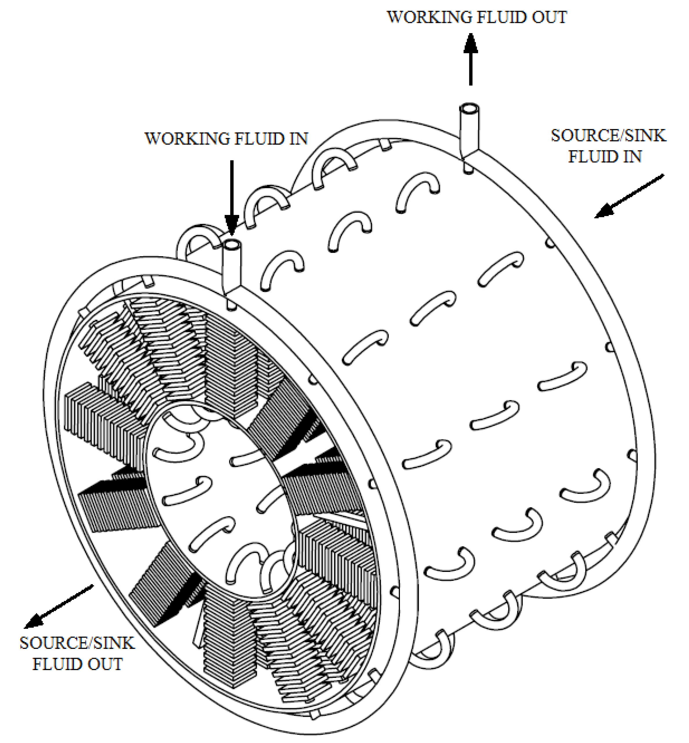
Figure 2.
Multi-views of Annular-Shaped Heat Exchanger with Finned-Tubes.
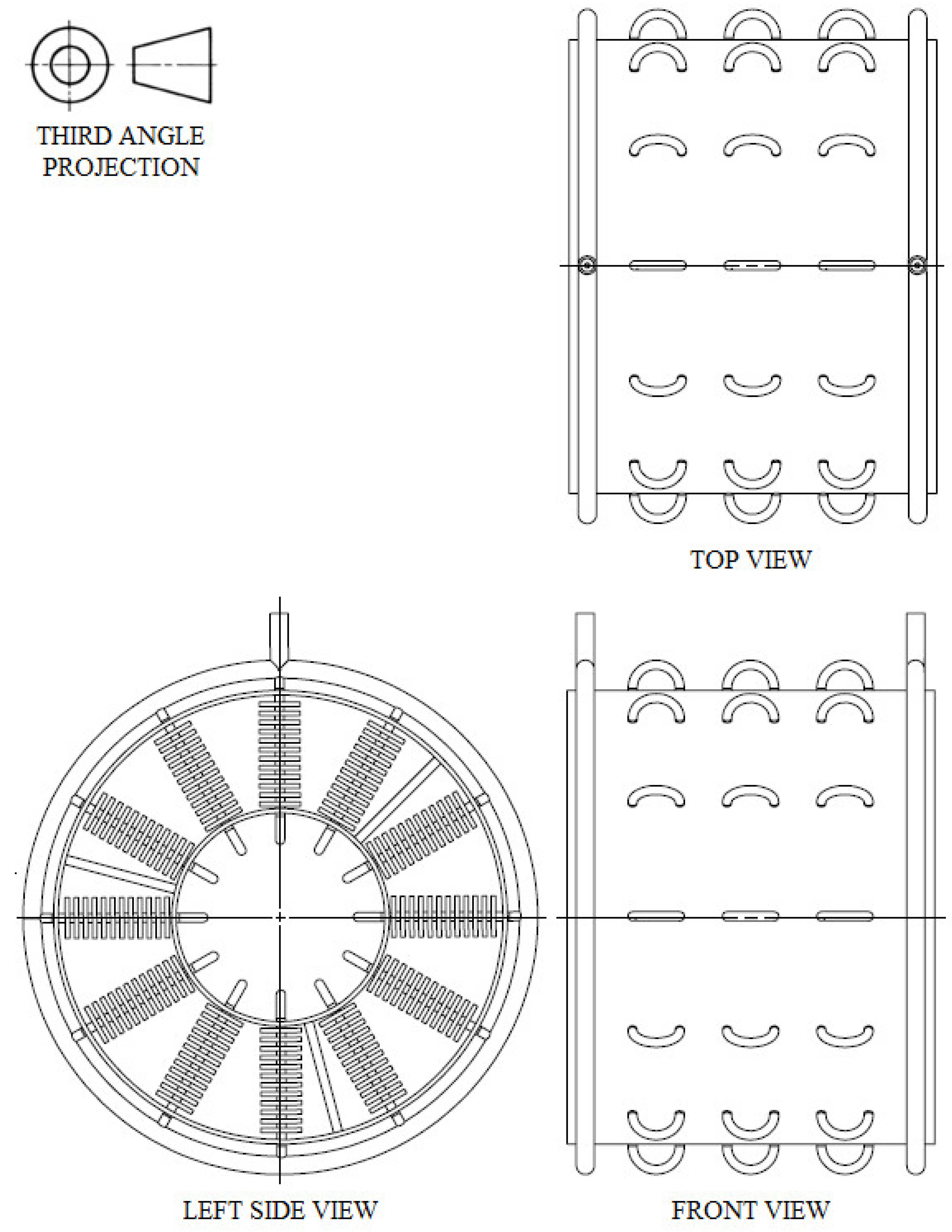
Figure 3.
Heat recovery system for direct drive shaft powered aircraft gas turbine engine with (a) turbo-expander mounted on exhaust shaft (b) turbo-expander installed outside engine framework and coupled to electric generator.
Figure 3.
Heat recovery system for direct drive shaft powered aircraft gas turbine engine with (a) turbo-expander mounted on exhaust shaft (b) turbo-expander installed outside engine framework and coupled to electric generator.
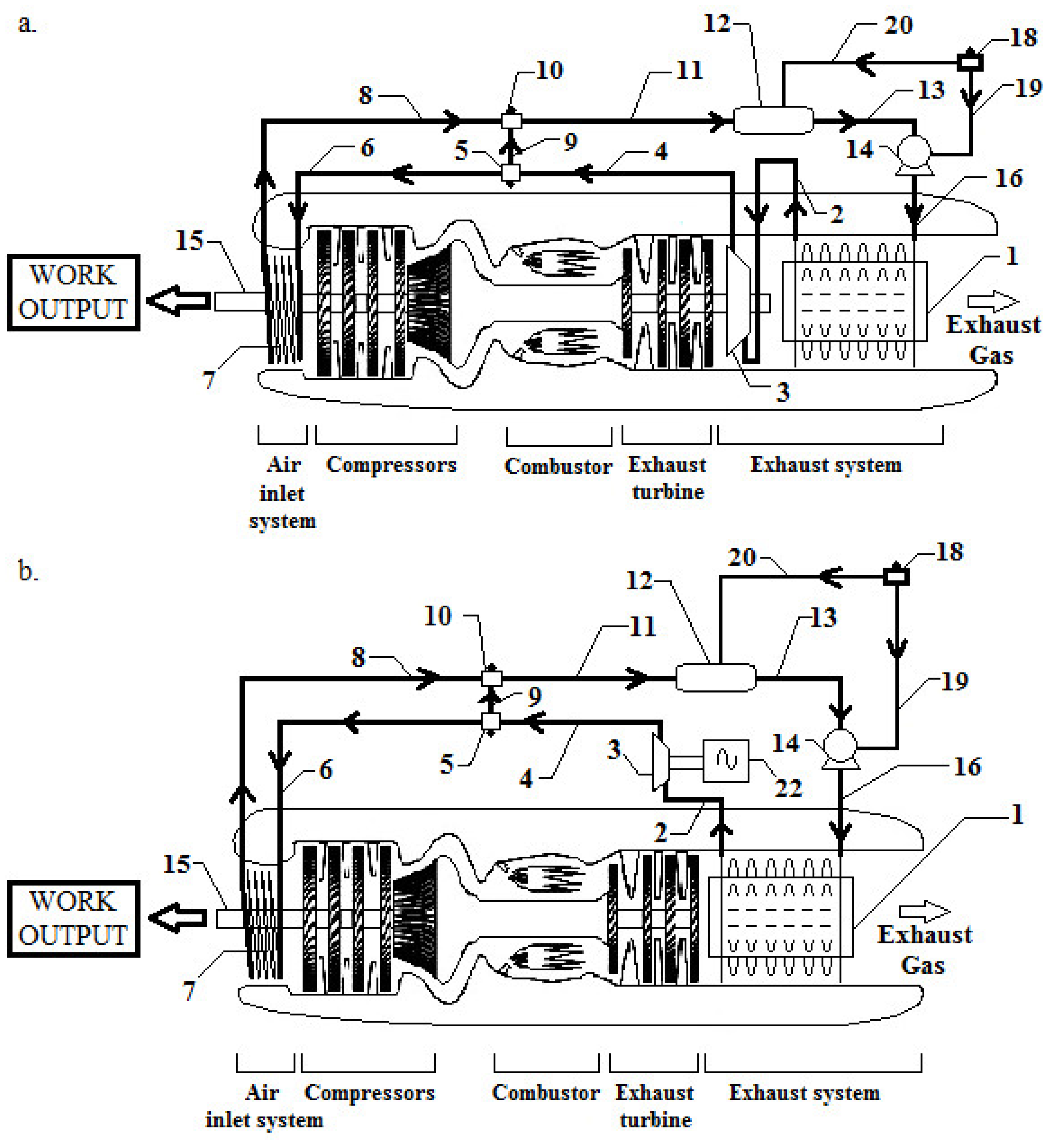
Figure 4.
Heat recovery system for reverse flow shaft powered aircraft gas turbine engine with (a) turbo-expander mounted on exhaust shaft (b) turbo-expander mounted on compressor shaft.
Figure 4.
Heat recovery system for reverse flow shaft powered aircraft gas turbine engine with (a) turbo-expander mounted on exhaust shaft (b) turbo-expander mounted on compressor shaft.
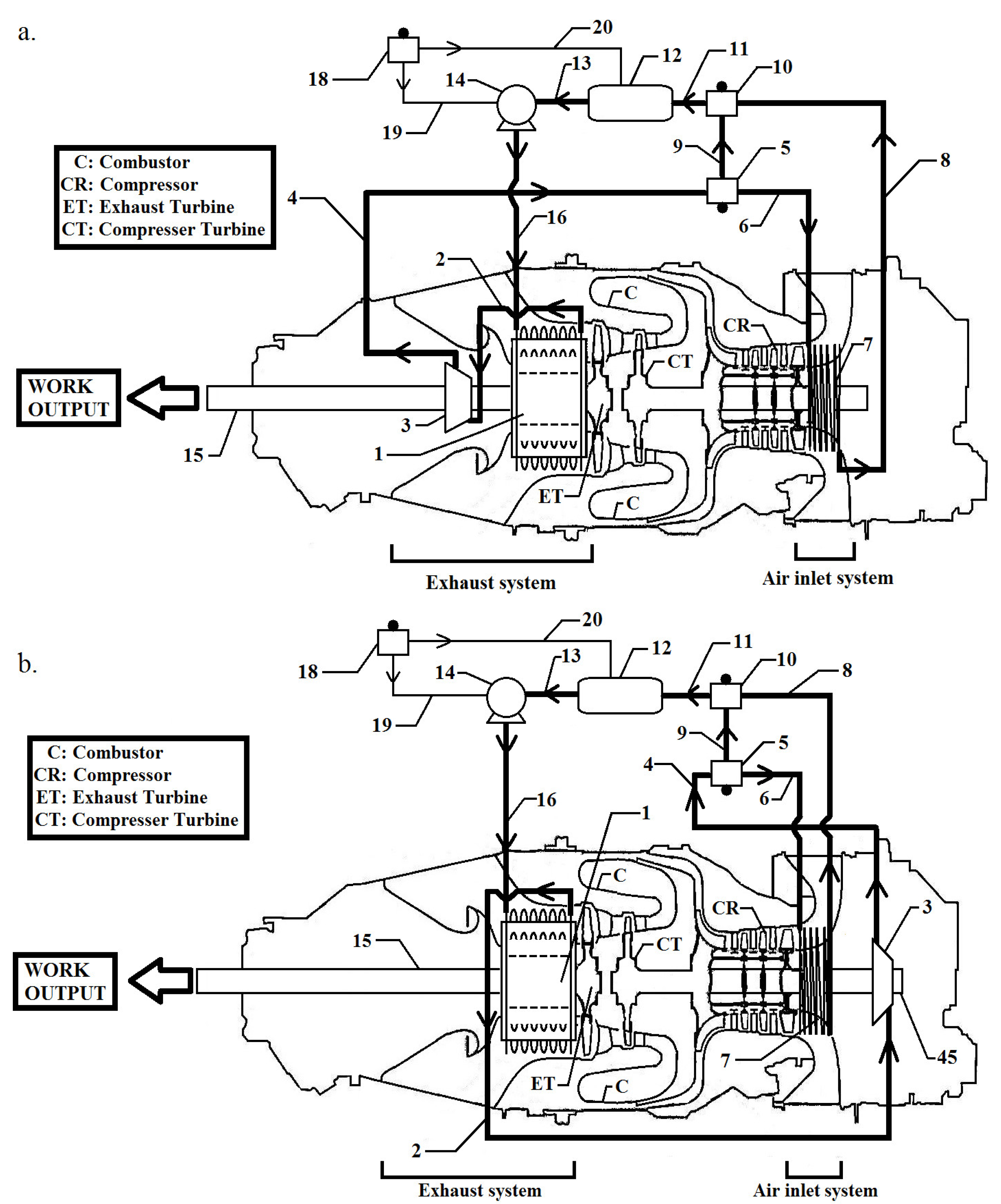
Figure 5.
Heat recovery system for reverse flow shaft powered aircraft gas turbine engine with turbo-expander installed outside engine framework and coupled to electric generator.
Figure 5.
Heat recovery system for reverse flow shaft powered aircraft gas turbine engine with turbo-expander installed outside engine framework and coupled to electric generator.
Disclaimer/Publisher’s Note: The statements, opinions and data contained in all publications are solely those of the individual author(s) and contributor(s) and not of MDPI and/or the editor(s). MDPI and/or the editor(s) disclaim responsibility for any injury to people or property resulting from any ideas, methods, instructions or products referred to in the content. |
© 2025 by the authors. Licensee MDPI, Basel, Switzerland. This article is an open access article distributed under the terms and conditions of the Creative Commons Attribution (CC BY) license (http://creativecommons.org/licenses/by/4.0/).
Copyright: This open access article is published under a Creative Commons CC BY 4.0 license, which permit the free download, distribution, and reuse, provided that the author and preprint are cited in any reuse.


