
Submitted:
15 January 2025
Posted:
15 January 2025
You are already at the latest version
Abstract
The 3D reconstruction of construction sites is of great importance for construction pro-gress, quality, and safety management. Currently, most of the existing 3D reconstruction methods are unable to conduct continuous and uninterrupted perception, and difficult to achieve registration with real coordinates and dimensions. This study proposes a hierar-chical registration framework for 3D reconstruction of construction sites based on surveil-lance cameras. This method can quickly perform on-site 3D reconstruction and restoration by taking fixed views such as surveillance camera images as inputs without transfer learning and camera calibration. This framework can complete the 3D point cloud esti-mation and registration of construction sites within an average of 3.105s through surveil-lance images. The average RMSE of the point cloud within the site is 0.358m, which is better than most point cloud registration methods. Through this method, 3D data within the scope of surveillance cameras can be quickly obtained, and the connection between 2D and 3D can be effectively established. Combined with visual information, it is beneficial to the digital twin management of construction sites.
Keywords:
image-based 3D reconstruction
; 3D computer vision
; surveillance camera
; Structure from Motion (SfM)
; point cloud registration
1. Introduction
The construction industry, as one of the important pillars of the global economy, is huge in scale. The total investment in global construction projects each year is as high as several trillion US dollars [1]. The application of automated monitoring technology for real-time monitoring of construction sites provides a new way to improve efficiency and safety in the construction industry [2]. By obtaining real-time and accurate information on the construction site, potential problems can be detected in a timely manner, the construction process can be optimized, and thus labor productivity can be improved. Among them, real-time 3D information is crucial for efficient monitoring and management. It plays an important role in project management, progress control, and safety monitoring.
With the expansion of the scale of modern construction projects, the demand for 3D reconstruction is increasing day by day. Especially in multiple stages of the building life cycle, high-precision digital modeling of the site is required. In recent years, in the construction field, technologies such as oblique photography + Structure from Motion and Multi-View Stereo (SfM-MVS) [3,4,5,6,7,8], laser scanning [9,10,11,12,13,14,15], and Simultaneous Localization and Mapping (SLAM) [16,17,18,19,20] have been mainly used as the main solutions for construction site reconstruction and are widely applied in practical tasks. However, most of the above methods have two problems:
- Lack of real-time performance: Special personnel are still required to carry out special measurement work regularly. The measurement frequency is low, and the processing time is relatively long, so it is impossible to reflect the dynamic changes of the construction site in real-time. When facing complex construction site environments, these methods often struggle to meet the needs of efficient and precise management.
- High-cost: The equipment costs required for some solutions are relatively high. In particular, the capital investment required for a terrestrial laser scanner (TLS) exceeds $50,000, and the minimum cost of professional mapping drones (PMDs) is $10,000 [21]. This is still a large investment for most projects, which also limits the popularization of 3D data collection on construction sites.
With the increasing complexity of construction scenarios, how to use continuous data sources such as low-cost, wide-range-sensing, and easy-to-deploy sensors for automated and accurate 3D reconstruction remains a key problem to be solved urgently. Surveillance cameras are one of the conventional means of construction site supervision. In most cases, surveillance cameras can cover most of the construction site. They are extremely important sources of visual data and have the advantages of continuity, uninterrupted operation, low investment cost, and no need for human intervention after operation. The near-real-time 3D reconstruction technology based on surveillance cameras can continuously and uninterruptedly obtain the visual data of the construction site, providing more intuitive and accurate spatial information for construction management.
In recent years, methods for real-time or near-real-time 3D reconstruction based on images have been widely studied and have attracted the attention of some researchers in the construction field. For 3D reconstruction methods based on images, we mainly focus on two types: monocular and binocular.
In monocular methods, monocular depth estimation is the main research direction. As a task in the computer field, it has made great progress. Models such as DepthFormer [22], ZoeDepth [23], and Depth Anything [24] have emerged continuously. In the construction scenario, to solve the problems of insufficient datasets and transfer learning, Shen et al. [25] collected a small amount of construction-scene image datasets and designed a new loss function of depth estimation. They also achieved scale recovery based on the human pose estimation, showing good depth-estimation results in the construction scenario. Subsequently, a self-supervised deep-learning method was proposed to further improve the depth-estimation performance and was combined with instance segmentation to achieve 3D object detection in monocular construction scenarios [26]. However, this study was only verified on depth datasets, lacking a comparison of scene-level 3D reconstruction results. In addition, some monocular methods correct the affine transformation of images according to known lines and geometric figures to calculate the position and distance of equipment [27], restore the 3D structure of buildings according to building axes [28], or calculate the mapping matrix between camera image pixels and plane coordinates based on the plane assumption [29,30]. To a certain extent, 3D information acquisition can be considered to be achieved, but the application scenarios are highly limited.
Binocular cameras are also one of the main methods for 3D reconstruction based on images [31,32,33]. By matching feature points between two views, the disparity is calculated, and then the 3D position of the corresponding points is calculated according to the calibrated position relationship and internal parameters between the two cameras, and finally, global reconstruction is achieved. In the construction field, Sung et al. [34] achieved terrain reconstruction with binocular cameras based on multi-scale descriptors (MSDs). He et al. [35] carried out binocular reconstruction of the construction site based on SGBM and verified the dynamic target trajectory tracking in the experimental device set up in the laboratory.
However, currently, the above 3D reconstruction methods and research based on images still have several problems:
- Size problem: For monocular depth estimation, due to the size ambiguity of monocular vision [36], although relative depth can be well estimated through a large amount of training, there are still difficulties in absolute depth estimation. The size benchmark for binocular 3D reconstruction is mainly based on the distance between the two cameras, also known as the baseline [33]. For commonly used binocular cameras currently, the baseline range is generally between a few centimeters and 1m, which can only be applied to indoor and short-distance scene reconstruction and cannot be directly applied to large-scale construction sites. In addition, binocular cameras generally require the two cameras to be in the same direction and horizontally aligned to facilitate the calculation of disparity, which makes the layout of surveillance cameras on site more complicated.
- Coordinate problem: The results obtained from 3D reconstruction methods based on images still need to be aligned to the real space. Usually, coordinate transformation is carried out through the calibrated camera internal and external parameters, which puts forward very high requirements for the accuracy of camera calibration. It is difficult to apply to non-fixed cameras, such as surveillance cameras that can be rotated and scaled. In addition, currently, the relevant research on 3D reconstruction based on images in the construction field has few verifications of real-space coordinates. For example, depth estimation mainly focuses on the accuracy of depth datasets, and binocular estimation focuses on the accuracy within the reconstruction range. There is a lack of a general method for the coordinate transformation of the reconstruction results.
- Difficult to deploy directly: Existing 3D reconstruction methods have high requirements for the deployment of acquisition equipment and parameter acquisition. For example, accurate calibration of camera internal and external parameters is a necessary step to convert depth-estimation results into 3D data. For binocular cameras, it is also necessary to adjust to parallel views in the same direction as much as possible. For the already-deployed surveillance camera systems, obtaining relevant accurate data still requires systematic measurement methods and corresponding adjustments.
In response to the above problems, the hierarchical framework based on surveillance cameras proposed in this study provides a new solution, aiming to offer a set of 3D reconstruction methods that can be directly deployed on existing surveillance cameras without the need for corresponding adjustments to the cameras. The tasks and contributions of this work are as follows:
- A hierarchical framework for point cloud estimation and point cloud registration based on learning is introduced to conduct 3D reconstruction of construction sites. Compared with methods such as those based on LiDAR and SfM, it has lower costs, a higher level of automation, can perform continuous reconstruction, is easier to implement, and does not require the annotation of internal and external parameters of monitoring equipment. Moreover, it does not need new data for transfer learning and can be directly deployed on-site.
- A point cloud registration method based on the results of 2D feature matching is proposed, which can conduct camera registration in the actual space, point cloud dimension restoration, and coordinate system registration. In terms of overall accuracy, it is superior to conventional point cloud registration methods. Compared with mainstream point cloud registration methods, the registration method proposed in this study has better robustness and adaptability.
- The proposed method has been subjected to extensive experiments on construction site datasets. The results show that the proposed 3D reconstruction framework is more efficient in terms of computational efficiency than mainstream reconstruction methods based on SfM-MVS, and the point cloud registration accuracy is higher than that of other point cloud registration methods, which can be further used for downstream tasks.
The content organization of this work is as follows: In Section 2, the proposed method for 3D reconstruction and registration of construction sites based on images from a small number of views is described in detail; In Section 3, the experiment of construction site and the evaluation metrics are described; In Section 4, the results are compared both quantitatively and qualitatively with those of existing methods; In Section 5, the conclusions and contributions of this work are summarized.
2. Methods
2.1. The Structure of the Framework
In this work, the authors designed a hierarchical framework by utilizing the RGB sensors of surveillance cameras arranged on construction sites for the 3D reconstruction of construction sites. The proposed method can realize the 3D reconstruction of point clouds within the sensing range. Compared with existing methods, it can yield more accurate results and meanwhile has satisfactory computational efficiency.
The 3D reconstruction framework of construction sites based on surveillance cameras is illustrated in Figure 1, and it encompasses three stages:
- Sparse point cloud reconstruction of Unmanned Aerial Vehicle (UAV) images: Employ the SfM method to conduct the reconstruction of sparse point cloud so as to obtain the spatial information of the scene;
- Initial point cloud estimation of surveillance images: Through the DUSt3R [37] model, take the images collected by surveillance cameras as inputs to obtain the initial point cloud. At this time, the point cloud is still in local coordinates and with estimated dimensions;
- Dimension restoration and coordinate restoration of the point cloud: Obtain the 3D point cloud with real dimensions and unify it into the same coordinate system. Conduct 2D-2D matching on sequence images and UAV images. Through the respective 2D-3D correspondence situations of the two images, map the matching results to the matching between 3D point clouds. Based on the situation of matching points, calculate the scaling coefficient, and calculate the rotation and translation matrix based on the RANSAC (Random Sample Consensus) [38] algorithm to register the point clouds.
2.2. Sparse Point Cloud Reconstruction
To obtain the initial 3D spatial information in construction scenes, using the SfM technology to acquire 3D point clouds is one of the commonly used techniques in engineering. Figure 2 shows the process of sparse point cloud reconstruction on construction sites. UAVsare used to conduct oblique photography around the construction site to take a series of pictures of the construction site. A certain overlap rate and coverage rate need to be ensured among these pictures. Subsequently, the sparse point cloud P is obtained through the SfM process, and this process can be referred to as photo alignment, which includes feature extraction and matching, global point matching and reconstruction.
The obtained 3D point clouds can generally correspond to the required coordinate system by marking control points or using the RTK-GPS positioning equipped with the UAV as the absolute coordinates of the camera, so as to ensure the authenticity of their dimensions and coordinates. The above process can be carried out by commercial software such as Agisoft Metashape and Pix4D, or by open-source tools like openmvg[39], colmap[40], and opensfm. The obtained sparse point cloud , with real dimension and coordinate information, will serve as the benchmark point cloud and benchmark space for the subsequent alignment of 3D information.
Since SfM involves a large number of feature point identifications and matchings, as well as Perspective-n-Point (PnP) and 3D reconstruction calculations, it usually takes a long time and is generally conducted through offline post-processing. In this work, the sparse point cloud reconstruction only needs to be carried out once before the subsequent processes, which effectively avoids the defect of the long time-consuming offline processing of SfM and does not affect the near real-time performance of the overall process.
For the obtained sparse point cloud, each point in it is called a tie point, which corresponds to the image feature points matched in the feature matching. Thus, the mapping relationship between the 2D points in the UAV images and the 3D points in the sparse point cloud can be obtained, and applied in the subsequent processes.
2.3. Initial Point Cloud Estimation
Initial point cloud estimation aims to achieve end-to-end estimation and generation from images to point clouds through deep learning algorithms. Based on deep learning network frameworks and large-scale image and point cloud pair data, end-to-end point cloud estimation based on images can be realized, such as the DUSt3R [37] algorithm. The DUSt3R can conduct dense stereo 3D reconstruction from the pictures taken by uncalibrated cameras with undetermined poses.
DUSt3R is an image-based unconstrained dense 3D reconstruction method and is the first overall end-to-end 3D reconstruction pipeline for uncalibrated and unposed images. Its model architecture is shown in Figure 3. Firstly, given two images and , the images are divided into patches and encoded. Through the shared Vision Transformer (ViT) encoder, the feature representations and are obtained:
Subsequently, through the transformer decoder that shares information, new features and with enhanced spatial information are obtained by means of cross-analysis of the features in the two views.
Finally, based on two predicted regression heads, two estimated point clouds and as well as their corresponding confidence levels and are regressed from the concatenated feature representations. The two point clouds are in the same coordinate system. Among them, the dimensions of and are (H, W, 3), and the dimensions of and are H × W, where H and W are the height and width of the images and respectively. Each 3D point and confidence value corresponds to a pixel point in the original image.
Compared with traditional depth estimation methods and binocular estimation methods, DUSt3R can integrate the visual information between binocular perspectives through its model architecture to obtain a three-dimensional spatial relationship with higher confidence, and it does not require the corresponding calibration of the camera, which enables it to be directly applied to the image acquisition devices deployed on site.
In the current work, we directly use the pre-trained model of DUSt3R for point cloud estimation without the need for an additional training process for the construction scene. The DUSt3R model has been trained on eight datasets[37], covering a variety of scenes such as indoor, outdoor, synthetic, real-world, and object-centered scenes. A total of 8.5 million pairs of images and point clouds were extracted for training. DUSt3R has been compared with other algorithms on multiple tasks such as monocular depth estimation and 3D reconstruction, demonstrating significant superior performance and generalization performance. From this perspective, it can be applied to the 3D reconstruction scene based on surveillance images of the construction scene.
Through DUSt3R, we can obtain the initial point cloud from surveillance images, and there is a one-to-one relationship between pixels and 3D spatial points. Due to the size effect of the point cloud based on visual estimation, the obtained point cloud Q is still in a relative scale. As shown in Figure 4, it is still difficult to match the size of the obtained construction site with the real site size, and they are not in the same coordinate system. Therefore, it is necessary to implement the restoration and alignment of the size and position of the point cloud through corresponding feature point matching and point cloud registration methods.
2.4.3. D point cloud Alignment Based on 2D Features (2DFM-RANSAC)
Usually, the point cloud registration methods based on feature points have a better correspondence when the feature point matching is accurate. For the purpose of point cloud registration, this study hopes to map the matching of 2D feature points to the matching relationship of 3D feature points, so as to apply it to point cloud registration. In this work, the authors propose a new 3D point cloud registration method based on 2D features, namely 2DFM (Two-dimensional feature matching)–RANSAC. The flowchart is shown in Figure 5, and it is divided into three steps: 2D feature point matching, 3D feature point matching, and point cloud scaling and registration.
Compared with common point cloud registration methods, this method can effectively solve the geometric degradation problem caused by the repetition of three-dimensional geometric features and the indistinct distinction in large and repetitive scenes, and has obvious advantages in the applicability of registration. Moreover, it can effectively solve the problem of size uncertainty existing in 3D reconstruction based on two-dimensional images, and provides a clear method for size and spatial position restoration.
2.4.1. 2D Feature Point Matching
To achieve the restoration of point clouds based on 2D features, this study first conducts 2D feature matching between the sequence images collected by surveillance cameras and the reference images taken by unmanned aerial vehicle. This study adopts the global feature point matching method developed based on DUSt3R. Firstly, given two images and , the DUSt3R algorithm is used for binocular view point cloud estimation to obtain two sets of estimated point clouds and as well as their corresponding confidence levels and . These two point clouds are in the same relative coordinate system.
Among them, is the confidence threshold. In this study, is set to 10, which is an empirical value. Through this limitation, the points with lower confidence are deleted, and the filtered point clouds and are obtained. Then, the pairs of points to be matched are selected, and KD trees are established respectively to search and query the pairs of mutually nearest neighbor points M between the two sets of points.
Since the 3D points in the point cloud correspond one-to-one with the pixel points in the image, based on the matching relationship of , the pixel point matching relationshipsand between and can also be obtained, where and .
Traditional feature point extraction and matching methods, such as SIFT [41], LIFT [42], ORB [43] and SuperPoint, all require multiple steps, including local feature point extraction, descriptor calculation, nearest neighbor matching, outlier removal, and solving geometric constraints. In the case where there are a large number of repeated 2D features or indistinct features in the images within the site, it is usually difficult to obtain excellent matching results. In contrast, the matching point information based on DUSt3R can fully integrate the global and local 2D feature information. It can share the 2D feature information within the model and directly give dense feature point pairs consistent in three dimensions based on the 3D relationship between the two pictures. Due to the complex situation at the construction site and the possible existence of many regions with repeated features or no features, such as flat ground and repetitive pile-column structures, by adopting the feature point matching method based on DUSt3R, we can obtain accurate, robust, and three-dimensionally consistent feature point pairs.
Regarding the selection of pictures for feature point matching, we take the oblique photography pictures taken by unmanned aerial vehicles as the reference image library and use NetVLAD [44] to find the most similar unmanned aerial vehicle images as reference images. By performing 2D feature point matching between the images collected in real-time by surveillance videos and the reference images, the matching results as shown in Figure 6 can be obtained.
In Figure 6, only 1,000 pairs of matching points are shown to ensure the visualization results. The number of matching feature point pairs obtained from the two images shown is 12,159, which demonstrates the density and spatial uniformity of the matching point pairs obtained by this method. This plays an important role in the global matching of point clouds in the subsequent process and can effectively avoid local matching caused by the situation that features matching is concentrated in a certain area or the interval distance is insufficient.
Meanwhile, in the overall method framework, the feature point matching in this step can also be replaced by two-dimensional feature matching methods such as SuperGlue [41]. As long as the matching accuracy is ensured, all two-dimensional feature point matching methods can be effectively applied to the existing process.
On this basis, to achieve the matching of 3D point features, it is also necessary to realize the matching of 3D feature points through the mapping relationship of corresponding algorithms. In the case of mismatching of 2D feature points, optimization based on three-dimensional space will also be carried out in the subsequent process to improve the matching accuracy.
2.4.2. 3D Feature Point Matching
3D feature point matching is a necessary process for point cloud registration based on feature points. In this study, based on the results of 2D feature point matching, combined with the mapping relationship between 2D pixel points in images and 3D tie points in sparse point clouds, namely and in SfM, as well as the 2D - 3D mapping relationship between images and initial point clouds obtained by DUSt3R, that is and, we achieve the transformation from 2D feature point matching to 3D feature point matching, namely and , realizing the mapping between point cloud and point cloud .
It should be noted that except for DUSt3R which fully realizes the mapping between all 2D pixels and 3D points, not all of the above matching relationships can cover all pixel points and 3D points. We need to take the intersection of the left and right sets of as the starting point of the overall mapping relationship. That is, we conduct the intersection according to the 2D tie point set of SfM and the q feature point set of 2D feature point matching and then perform mapping on the left and right sides respectively. Since all the above matching relationships are one-to-one matches, forward and reverse mappings will not affect the matching results. Thus, the 3D feature point matching between P and Q is achieved.
Cross-source point clouds refer to point clouds from different sources, such as laser - scanned point clouds, point clouds estimated from images, and SfM point clouds. Due to differences in sensors and acquisition methods, there are often disparities in point cloud distribution, scale, and density, which result in inconsistent 3D features. By using 2D feature points as a link to conduct 3D feature point matching, it can effectively solve the problems of difficulties in 3D feature point matching caused by the inconsistent sizes between two point clouds and the inconsistency of 3D features of cross-source point clouds.
2.4.3. Point Cloud Scaling and Alignment
In order to restore the initially estimated point cloud to its real size, it is necessary to conduct point cloud scaling and registration. The scaling factor between the initial point cloud and the final required point cloud, as well as the rotation matrix and the translation vector , need to be calculated. The specific matrices are used to estimate the restoration of the point cloud in two stages, namely point cloud scaling and point cloud registration.
Among them, is the scaling factor of the similarity transformation, is the rotation matrix, and is the translation vector.
Point cloud scaling. In order to restore the initial point cloud obtained based on DUSt3R to its real size, it is necessary to calculate the corresponding scaling factor. Based on the matching results of 3D feature points, two pairs of feature points and can be selected from the initial point cloud P and the reference sparse point cloud Q respectively, and the ratio between the lengths of the lines connecting the two sets of feature points can be calculated. The formula is as follows.
We conduct corresponding statistics on the ratios calculated through a large number of feature point connection pairs. The visualization results are shown in Figure 7. It can be seen that the distribution is basically symmetrical on both sides, and the median is basically consistent with the mode of the statistical group. In this study, we take the median of the scaling factors as the final scaling ratio .
Point cloud registration. In the point cloud registration stage, the authors choose the RANSAC method [38] as the point cloud registration scheme. It is the most widely used robust fitting method, and its basic idea relies on the hypothesis and verification techniques. RANSAC alternately performs the sampling of the minimum subset and model fitting until the stopping criterion is met.
RANSAC has relatively strong robustness. It iterates over random subsets of feature point pairs, calculates the rotation matrix and translation vector based on these subsets, transforms the remaining feature point pairs according to the calculation results, screens the transformation results according to the corresponding distance threshold, and then judges to conduct the iterative calculation of the inlier set, excludes outliers, and takes the transformation result with the largest number of inliers as the best transformation, thus obtaining relatively consistent registration results within the overall scope. Relevant studies have shown that the RANSAC algorithm also has an advantage in computational speed. Based on the 3D feature point matching results obtained in the previous subsection, we conduct RANSAC point cloud registration calculations based on the set of feature point pairs, and then we can obtain the corresponding rotation matrix and translation vector .
Up to now, it is possible for us to estimate the point cloud based on one surveillance picture on the basis of conducting oblique photography by unmanned aerial vehicles and restore it to the real size and coordinate system.
3. Experiment
3.1. Experiments Setup
In order to test the effectiveness and performance of the proposed method and compare it with mainstream point cloud registration methods, this study conducted tests in the construction site scene, as shown in Figure 8. The tests evaluated the reconstruction effect in large construction scenes, which posed a challenge to the robustness of the reconstruction methods.
The authors conducted experiments based on the image dataset collected by the Technical University of Munich in Germany [30]. The specific situation is shown in Figure 8. The experimenters selected an under-construction research building with a floor area of 1,000 square meters, which measures 25m*40m, as the experimental site. In this
experimental scenario, UAVs were used to take images and collect videos of the construction scene with a resolution of 3840*2160 pixels. Meanwhile, three surveillance cameras were deployed on the tower crane with a resolution of 3840*2160 pixels. Their heights from the ground were 30.2m, 28.2m, and 14.3m respectively. Their viewing angles would change as the crane operated, and the direction of the viewing angles could also be changed through the control system, as shown in Figure 8.a. Based on the pictures and videos provided in the dataset, the authors extracted a total of 339 UAV images as the benchmark images for the 3D point cloud reconstruction of oblique photography. The resulting orthophotos and sparse point clouds are shown in Figure 8.b and 8.c. In addition, 101 images from the surveillance cameras were selected as the sequence images for verifying the 3D point cloud reconstruction algorithm proposed in this paper.
In the evaluation of the accuracy of 3D reconstruction, experimenters usually take the results obtained through SfM-MVS or laser 3D point clouds as the ground truth and analyze the accuracy by calculating the errors of point clouds. When the UAV images meet the requirements regarding the number, quality, and overlap, and with the reasonable arrangement of ground control points (GCPs), the error of the point cloud results obtained through SfM-MVS for 3D reconstruction is generally at the centimeter level [5,7]. In the above experiments, we used UAVs to conduct oblique photography and reconstructed the encrypted 3D point clouds from the UAV images through SfM-MVS to obtain the real 3D spatial information, so as to evaluate and compare the reconstruction results obtained by the algorithm.
Evaluation Metrics
To evaluate the accuracy of the 3D reconstructed point cloud, this study adopts the distance between point clouds as the error measurement indicator. In the experiment, the encrypted point cloud obtained from the UAV images through SfM-MVS is taken as the ground truth, and the point to point distance between the point cloud reconstructed from the surveillance images and the encrypted point cloud is regarded as the error. The formula for the point to point distance is as follows:
Due to the influence of point clouds of trees and other objects around the construction site, this study only focuses on the reconstruction results within the construction site. Through the preset area of concern, the SfM-MVS point cloud and the point cloud to be compared are cropped based on the same xy plane range. Subsequently, the point cloud distance from the point cloud to be compared to the cropped SfM-MVS point cloud is calculated as the point cloud error, as shown in Figure 9.
To further quantitatively compare the errors, the researchers adopted four commonly used indicators, including mean error (ME), error standard , median error, Root Mean Square Error (RMSE).
4. Results and Discussion
4.1. Performance of 2DFM-RANSAC
To verify the advantages of the proposed point cloud reconstruction method, the authors compared the proposed method with existing point cloud registration methods, which include: (1) Global registration methods: RANSAC based on FPFH (Fast Point Feature Histograms) [45], and FGR (Fast Global Registration) [46] based on FPFH; (2) Fine registration methods: ICP (Iterative Closest Point) Point to Point and ICP Point to Plane.
FPFH [45] is a feature descriptor used to describe the local geometric features of 3D point clouds. It plays an important role in the field of point cloud processing, especially in tasks such as point cloud registration. It is based on the local neighborhood information of points in the point cloud. ICP [47,48] is a classic algorithm used for point cloud registration. Its main aim is to find the optimal rigid body transformation, including rotation and translation, between two point clouds, so that one point cloud can be aligned with the other as accurately as possible. The ICP algorithm usually requires an initial transformation estimate to start the iterative process. Subsequently, it conducts the search for the closest points, the calculation of the transformation, and the iterative update. Eventually, it gives the final transformation when certain stopping criteria are met.
Among them, since ICP requires a rotation and displacement matrix as the initial transformation, in the normal operation process, the registration results of RANSAC or FGR are usually input as the initial transformation of ICP. Considering that the existing global registration methods have relatively large errors in the current scenario, in this study, the registration results of 2DFM-RANSAC were offset to a certain extent and then input as the initial transformation of ICP. In this study, the offset parameters we selected were 1m, 1m, 1m, and an offset of 5 degrees along the z-axis, which are significantly better than the results of FPFH-RANSAC and FPFH-FGR. Moreover, for 2DFM-RANSAC, there is no need for a corresponding initial rotation matrix. In other words, it can be applied under circumstances where the offset is much larger than these parameters. Besides, for the ICP algorithm, down sampling is generally carried out. In this study, following the examples of Open3D [49], 0.25m and 0.05m voxel grid filtering were respectively selected as the down sampling parameters based on the site size.
The results of various point cloud registration methods are shown in Figure 10. In the figure, the reference point cloud and the final point cloud were visualized together. It can be seen that in the working conditions shown, our proposed method 2DFM-RANSAC exhibited good performance. It was significantly superior to other point cloud registration methods, whether in the orientation of the overall point cloud or in the matching of details.
For the compared global registration methods, most of them had completely incorrect matching situations. This was because cross-source point clouds, due to their different sources, led to inconsistent point cloud densities and three-dimensional shapes, and they did not have similarities in local 3D point features, which made it easy to have mis-matching when performing feature point matching through FPFH. For the compared fine matching algorithms, they could effectively obtain relatively good results under the initial conditions with a certain offset, but there were still some offsets in some scenarios, and mismatches in the details of the site could be observed.
The quantitative error evaluation of each registration method is shown in Table 1. The table presents the average values of the quantitative evaluation indicators for the working conditions of the 101 tested photos. Under the comprehensive consideration of various evaluation indicators, the proposed method is superior to the comparison methods. For the global matching methods, the proposed method can reduce the RMSE from 1.915m to 0.358m, a decrease of 81.3%, and the calculation time is decreased from 25.929s to 2.474s, which also illustrates the advantages of the proposed method in terms of accuracy and speed. Compared with the fine matching methods, all the errors of the proposed method are smaller than those of the comparison methods. Considering that the fine matching methods require an initial transformation as a basis, while this method does not need initialization and can achieve point cloud registration in one step, it also demonstrates the advantages of this method.
Meanwhile, in order to show the variation range of errors of each method under different working conditions, Figure 11 shows the error distribution of each working condition. Since the errors of the global registration methods are relatively large, they are not shown in Figure 11. It can be seen that under the two indicators of mean error and RMSE, compared with the other several methods, the overall error distribution of 2DFM-RANSAC is smaller than that of the other methods. In the case of standard error, the overall distribution of 2DFM-RANSAC is lower than that of the other methods, but there are a few outliers, which are caused by whether the error distribution is uniform or not.
4.2. Computational Efficiency
In order to evaluate the computational efficiency of the proposed method, the authors performed 3D reconstruction tasks on a computer equipped with an Intel i7-9700 CPU and a GPU GTX4060 with Python programming language. The average speed of a single reconstruction of the DUSt3R was 0.631s, with 92.3% of the working conditions being able to complete the reconstruction of the initial point cloud in less than 0.8s.
Figure 13 illustrates the running time of a point cloud and compares it with other point cloud registration methods. Since the running time of global registration methods is too long, they are not shown in this figure. The results show that the proposed method is generally faster than the ICP algorithm. By making full use of the capabilities of the CPU and GPU, the proposed framework can meet the requirements for online 3D reconstruction of construction sites based on surveillance cameras.
5. Conclusions
Surveillance cameras have the advantages of low cost and convenient deployment, and have been widely used in construction sites. Considering the above background, this study introduces a pioneering method framework for the rapid 3D reconstruction of construction sites based on surveillance cameras. Through three stages, namely sparse point cloud reconstruction, initial point cloud estimation, and point cloud registration, it can effectively utilize the surveillance cameras already arranged at the construction site to conduct comprehensive monitoring of the construction site from various angles. This method integrates advanced technologies such as image-based 3D point cloud estimation, 3D reconstruction based on SfM-MVS, and image and point cloud feature matching, thereby improving the availability of surveillance cameras for the acquisition of 3D information and further ensuring the authenticity of size and position. This paper introduce a breakthrough point cloud registration technology based on 2D features, which plays a crucial role in restoring the real size and position of the reconstructed point cloud. This innovation significantly optimizes the accuracy and speed of point cloud registration, making it possible for 3D reconstruction and perception to be carried out by surveillance cameras in near real time. This progress greatly improves the efficiency of 3D data collection at construction sites, thus providing support for the refined management of construction sites based on 3D data. The main research results of this study are summarized as follows:
A near real-time 3D data perception framework that does not require the internal and external parameters of on-site surveillance cameras was proposed. Based on the DUSt3R method, surveillance cameras can be applied to the 3D information perception and reconstruction of construction sites based on the collected images without the need for internal and external parameter calibration. It can be quickly deployed on the existing image acquisition devices at construction sites, with an average reconstruction speed of 3.105s, enabling near real-time 3D reconstruction of construction sites. This framework can directly obtain the true 3D spatial coordinates corresponding to each pixel. Consequently, it can be seamlessly integrated with image algorithms and applied to specific tasks.;
A method for unifying the spatial perception data of construction scenes based on SfM sparse point clouds was proposed. Before this, solving the size problem of 3D estimation based on images was difficult for many studies. In this study, focusing on the characteristics of continuous renovation at construction sites, by establishing SfM sparse point clouds as the size and coordinate benchmarks, it is possible to restore the estimated point clouds to their real sizes and positions through automated means;
Based on 2D semantic features for point cloud registration, the 2DFM-RANSAC method was proposed. By using image feature matching, it effectively solves the problems of relative size differences in point clouds and the inconsistency of 3D features of cross-source point clouds. Meanwhile, it improves the accuracy and speed of registration. In the experiment on a construction site with a size of 25m*40m, the RMSE is 0.358m, mean error is 0.268m, and the average registration speed reaches 2.474s, which are superior to the compared methods.
There are still some improvements that will be made to this study in the future as follows: (1) we will incorporate a data update process to dynamically update the 3D data of the construction site through the surveillance video stream, so that the reconstructed point cloud and the on-site sparse point cloud can be updated to the latest state in real-time. (2) we will study the impact of different camera layouts on reconstruction effect to overcome the accuracy impact caused by images from various perspectives and distances in 3D construction site reconstruction. (3) we will combine this technology with image target recognition and tracking to achieve the positioning and tracking of humans, machines and objects at the construction site, thereby enabling the comprehensive and real-time safety monitoring and progress monitoring of the construction site.
Author Contributions
Conceptualization, X.A.; methodology, A.S.; validation, A.S. and W.L.; formal analysis, A.S. and X.A.; investigation, X.A. and M.L.; resources, X.A. and M.L.; data curation, A.S.; writing—original draft preparation, A.S. and W.L.; writing—review and editing, X.A., P.L. and M.L.; visualization, A.S.; supervision, X.A. and P.L.; project administration, X.A. and M.L.; funding acquisition, X.A. and P.L. All authors have read and agreed to the published version of the manuscript.
Funding
This research was funded by the State Key Laboratory of Hydroscience and Engineering, grant number sklhse-TD-2024-D01, and the Chongqing Natural Science Foundation of China, grant number CSTB2022NSCQ-MSX0509.
Data Availability Statement
The data that support the findings of this study are available from the corresponding author upon reasonable request. The data are not publicly available due to confidentiality restrictions.
Acknowledgments
The authors would like to acknowledge Fabian Pfitzner (Chair of Computational Modeling and Simulation from the Technical University of Munich) and his laboratory for providing the dataset for research.
Conflicts of Interest
The authors declare no conflicts of interest.
References
- Amiri, A.F.; Bausman, D. The Internationalization of Construction Industry-A Global Perspective. International Journal of Engineering Science Invention (IJESI) 2018, 7, 59–68. [Google Scholar]
- Rao, A.S.; Radanovic, M.; Liu, Y.; Hu, S.; Fang, Y.; Khoshelham, K.; Palaniswami, M.; Ngo, T. Real-Time Monitoring of Construction Sites: Sensors, Methods, and Applications. Automation in Construction 2022, 136, 104099. [Google Scholar] [CrossRef]
- Keyvanfar, A.; Shafaghat, A.; Rosley, M.S. Performance Comparison Analysis of 3D Reconstruction Modeling Software in Construction Site Visualization and Mapping. International Journal of Architectural Computing 2022, 20, 453–475. [Google Scholar] [CrossRef]
- Corradetti, A.; Seers, T.; Mercuri, M.; Calligaris, C.; Busetti, A.; Zini, L. Benchmarking Different SfM-MVS Photogrammetric and iOS LiDAR Acquisition Methods for the Digital Preservation of a Short-Lived Excavation: A Case Study from an Area of Sinkhole Related Subsidence. Remote Sensing 2022, 14, 5187. [Google Scholar] [CrossRef]
- Zhao, S.; Kang, F.; Li, J.; Ma, C. Structural Health Monitoring and Inspection of Dams Based on UAV Photogrammetry with Image 3D Reconstruction. Automation in Construction 2021, 130, 103832. [Google Scholar] [CrossRef]
- Braun, A.; Tuttas, S.; Borrmann, A.; Stilla, U. Improving Progress Monitoring by Fusing Point Clouds, Semantic Data and Computer Vision. Automation in Construction 2020, 116, 103210. [Google Scholar] [CrossRef]
- Zhao, S.; Kang, F.; Li, J. Concrete Dam Damage Detection and Localisation Based on YOLOv5s-HSC and Photogrammetric 3D Reconstruction. Automation in Construction 2022, 143, 104555. [Google Scholar] [CrossRef]
- Xiao, J.-L.; Fan, J.-S.; Liu, Y.-F.; Li, B.-L.; Nie, J.-G. Region of Interest (ROI) Extraction and Crack Detection for UAV-Based Bridge Inspection Using Point Cloud Segmentation and 3D-to-2D Projection. Automation in Construction 2024, 158, 105226. [Google Scholar] [CrossRef]
- El-Omari, S.; Moselhi, O. Integrating 3D Laser Scanning and Photogrammetry for Progress Measurement of Construction Work. Automation in Construction 2008, 18, 1–9. [Google Scholar] [CrossRef]
- El-Omari, S.; Moselhi, O. Integrating Automated Data Acquisition Technologies for Progress Reporting of Construction Projects. Automation in Construction 2011, 20, 699–705. [Google Scholar] [CrossRef]
- Xiong, X.; Adan, A.; Akinci, B.; Huber, D. Automatic Creation of Semantically Rich 3D Building Models from Laser Scanner Data. Automation in Construction 2013, 31, 325–337. [Google Scholar] [CrossRef]
- Liu, T.; Wang, N.; Fu, Q.; Zhang, Y.; Wang, M. Research on 3D Reconstruction Method Based on Laser Rotation Scanning. In Proceedings of the 2019 IEEE International Conference on Mechatronics and Automation (ICMA); August 2019; pp. 1600–1604. [Google Scholar] [CrossRef]
- Hosamo, H.H.; Hosamo, M.H. Digital Twin Technology for Bridge Maintenance Using 3D Laser Scanning: A Review. Advances in Civil Engineering 2022, 2022, 2194949. [Google Scholar] [CrossRef]
- Li, J.; Peng, Y.; Tang, Z.; Li, Z. Three-Dimensional Reconstruction of Railway Bridges Based on Unmanned Aerial Vehicle–Terrestrial Laser Scanner Point Cloud Fusion. Buildings 2023, 13, 2841. [Google Scholar] [CrossRef]
- Piekarczuk, A.; Mazurek, A.; Szer, J.; Szer, I. A Case Study of 3D Scanning Techniques in Civil Engineering Using the Terrestrial Laser Scanning Technique. Buildings 2024, 14, 3703. [Google Scholar] [CrossRef]
- Lagüela, S.; Dorado, I.; Gesto, M.; Arias, P.; González-Aguilera, D.; Lorenzo, H. Behavior Analysis of Novel Wearable Indoor Mapping System Based on 3D-SLAM. Sensors 2018, 18, 766. [Google Scholar] [CrossRef] [PubMed]
- Xu, L.; Feng, C.; Kamat, V.R.; Menassa, C.C. A Scene-Adaptive Descriptor for Visual SLAM-Based Locating Applications in Built Environments. Automation in Construction 2020, 112, 103067. [Google Scholar] [CrossRef]
- Lu, T.; Tervola, S.; Lü, X.; Kibert, C.J.; Zhang, Q.; Li, T.; Yao, Z. A Novel Methodology for the Path Alignment of Visual SLAM in Indoor Construction Inspection. Automation in Construction 2021, 127, 103723. [Google Scholar] [CrossRef]
- Feng, C.-Q.; Li, B.-L.; Liu, Y.-F.; Zhang, F.; Yue, Y.; Fan, J.-S. Crack Assessment Using Multi-Sensor Fusion Simultaneous Localization and Mapping (SLAM) and Image Super-Resolution for Bridge Inspection. Automation in Construction 2023, 155, 105047. [Google Scholar] [CrossRef]
- Yarovoi, A.; Cho, Y.K. Review of Simultaneous Localization and Mapping (SLAM) for Construction Robotics Applications. Automation in Construction 2024, 162, 105344. [Google Scholar] [CrossRef]
- Zhang, N.; Lan, X. Everyday-Carry Equipment Mapping: A Portable and Low-Cost Method for 3D Digital Documentation of Architectural Heritage by Integrated iPhone and Microdrone. Buildings 2025, 15, 89. [Google Scholar] [CrossRef]
- Li, Z.; Chen, Z.; Liu, X.; Jiang, J. DepthFormer: Exploiting Long-Range Correlation and Local Information for Accurate Monocular Depth Estimation. Mach. Intell. Res. 2023. [Google Scholar] [CrossRef]
- Bhat, S.F.; Birkl, R.; Wofk, D.; Wonka, P.; Müller, M. ZoeDepth: Zero-Shot Transfer by Combining Relative and Metric Depth. arXiv 2023. [Google Scholar] [CrossRef]
- Yang, L.; Kang, B.; Huang, Z.; Xu, X.; Feng, J.; Zhao, H. Depth Anything: Unleashing the Power of Large-Scale Unlabeled Data. In Proceedings of the 2024 IEEE/CVF Conference on Computer Vision and Pattern Recognition (CVPR); June 2024; pp. 10371–10381. [Google Scholar] [CrossRef]
- Shen, J.; Yan, W.; Qin, S.; Zheng, X. A Self-Supervised Monocular Depth Estimation Model with Scale Recovery and Transfer Learning for Construction Scene Analysis. Computer-Aided Civil and Infrastructure Engineering 2022, 38, 1142–1161. [Google Scholar] [CrossRef]
- Shen, J.; Jiao, L.; Zhang, C.; Peng, K. Monocular 3D Object Detection for Construction Scene Analysis. Computer-Aided Civil and Infrastructure Engineering 2024, 39, 1370–1389. [Google Scholar] [CrossRef]
- Kim, D.; Liu, M.; Lee, S.; Kamat, V.R. Remote Proximity Monitoring between Mobile Construction Resources Using Camera-Mounted UAVs. Automation in Construction 2019, 99, 168–182. [Google Scholar] [CrossRef]
- Xu, B.; Liu, C. A 3D Reconstruction Method for Buildings Based on Monocular Vision. Computer-Aided Civil and Infrastructure Engineering 2022, 37, 354–369. [Google Scholar] [CrossRef]
- Qiu, W.-X.; Han, J.-Y.; Chen, A.Y. Measuring In-Building Spatial-Temporal Human Distribution through Monocular Image Data Considering Deep Learning–Based Image Depth Estimation. Journal of Computing in Civil Engineering 2021, 35, 04021014. [Google Scholar] [CrossRef]
- Pfitzner, F.; Braun, A.; Borrmann, A. From Data to Knowledge: Construction Process Analysis through Continuous Image Capturing, Object Detection, and Knowledge Graph Creation. Automation in Construction 2024, 164, 105451. [Google Scholar] [CrossRef]
- Zhong, W.; Dong, X. Camera Calibration Method of Binocular Stereo Vision Based on OpenCV. In Proceedings of the AOPC 2015: Image Processing and Analysis; SPIE, October 8 2015; Vol. 9675; pp. 571–576. [CrossRef]
- Liu, Y.; Li, C.; Gong, J. An Object Reconstruction Method Based on Binocular Stereo Vision. In Proceedings of the Intelligent Robotics and Applications; Springer International Publishing: Cham, 2017; pp. 486–495. [Google Scholar] [CrossRef]
- Lin, X.; Wang, J.; Lin, C. Research on 3D Reconstruction in Binocular Stereo Vision Based on Feature Point Matching Method. In Proceedings of the 2020 IEEE 3rd International Conference on Information Systems and Computer Aided Education (ICISCAE); September 2020; pp. 551–556. [Google Scholar] [CrossRef]
- Sung, C.; Kim, P.Y. 3D Terrain Reconstruction of Construction Sites Using a Stereo Camera. Automation in Construction 2016, 64, 65–77. [Google Scholar] [CrossRef]
- He, J.; Li, P.; An, X.; Wang, C. A Reconstruction Methodology of Dynamic Construction Site Activities in 3D Digital Twin Models Based on Camera Information. Buildings 2024, 14, 2113. [Google Scholar] [CrossRef]
- Yin, W.; Zhang, C.; Chen, H.; Cai, Z.; Yu, G.; Wang, K.; Chen, X.; Shen, C. Metric3D: Towards Zero-Shot Metric 3D Prediction from A Single Image. In Proceedings of the 2023 IEEE/CVF International Conference on Computer Vision (ICCV); October 2023; pp. 9009–9019. [Google Scholar] [CrossRef]
- Wang, S.; Leroy, V.; Cabon, Y.; Chidlovskii, B.; Revaud, J. DUSt3R: Geometric 3D Vision Made Easy. In Proceedings of the 2024 IEEE/CVF Conference on Computer Vision and Pattern Recognition (CVPR); June 2024; pp. 20697–20709. [Google Scholar] [CrossRef]
- Yang, S.-W.; Wang, C.-C.; Chang, C.-H. RANSAC Matching: Simultaneous Registration and Segmentation. In Proceedings of the 2010 IEEE International Conference on Robotics and Automation; May 2010; pp. 1905–1912. [Google Scholar] [CrossRef]
- Moulon, P.; Monasse, P.; Perrot, R.; Marlet, R. OpenMVG: Open Multiple View Geometry. In Proceedings of the Reproducible Research in Pattern Recognition; Kerautret, B., Colom, M., Monasse, P., Eds.; Springer International Publishing: Cham, 2017; pp. 60–74. [CrossRef]
- Schönberger, J.L.; Frahm, J.-M. Structure-from-Motion Revisited. In Proceedings of the 2016 IEEE Conference on Computer Vision and Pattern Recognition (CVPR); June 2016; pp. 4104–4113. [Google Scholar] [CrossRef]
- Ng, P.C.; Henikoff, S. SIFT: Predicting Amino Acid Changes That Affect Protein Function. Nucleic Acids Research 2003, 31, 3812–3814. [Google Scholar] [CrossRef] [PubMed]
- Yi, K.M.; Trulls, E.; Lepetit, V.; Fua, P. LIFT: Learned Invariant Feature Transform. In Proceedings of the Computer Vision – ECCV 2016; Leibe, B., Matas, J., Sebe, N., Welling, M., Eds.; Springer International Publishing: Cham, 2016; pp. 467–483. [Google Scholar] [CrossRef]
- Rublee, E.; Rabaud, V.; Konolige, K.; Bradski, G. ORB: An Efficient Alternative to SIFT or SURF. In Proceedings of the 2011 International Conference on Computer Vision; November 2011; pp. 2564–2571. [Google Scholar] [CrossRef]
- Arandjelović, R.; Gronat, P.; Torii, A.; Pajdla, T.; Sivic, J. NetVLAD: CNN Architecture for Weakly Supervised Place Recognition. IEEE Transactions on Pattern Analysis and Machine Intelligence 2018, 40, 1437–1451. [Google Scholar] [CrossRef] [PubMed]
- Rusu, R.B.; Blodow, N.; Beetz, M. Fast Point Feature Histograms (FPFH) for 3D Registration. In Proceedings of the 2009 IEEE International Conference on Robotics and Automation; May 2009; pp. 3212–3217. [Google Scholar] [CrossRef]
- Zhou, Q.-Y.; Park, J.; Koltun, V. Fast Global Registration. In Proceedings of the Computer Vision – ECCV 2016; Leibe, B., Matas, J., Sebe, N., Welling, M., Eds.; Springer International Publishing: Cham, 2016; pp. 766–782. [Google Scholar] [CrossRef]
- Besl, P.J.; McKay, N.D. Method for Registration of 3-D Shapes. In Proceedings of the Sensor Fusion IV: Control Paradigms and Data Structures; SPIE, April 30 1992; Vol. 1611, pp. 586–606. [CrossRef]
- Rusinkiewicz, S.; Levoy, M. Efficient Variants of the ICP Algorithm. In Proceedings of the Proceedings Third International Conference on 3-D Digital Imaging and Modeling; May 2001; pp. 145–152. [Google Scholar] [CrossRef]
- ICP Registration - Open3D 0.19.0 Documentation. Available online: https://www.open3d.org/docs/release/tutorial/t_pipelines/t_icp_registration.html (accessed on 14 January 2025).
Figure 1.
3D reconstruction framework based on surveillance cameras.
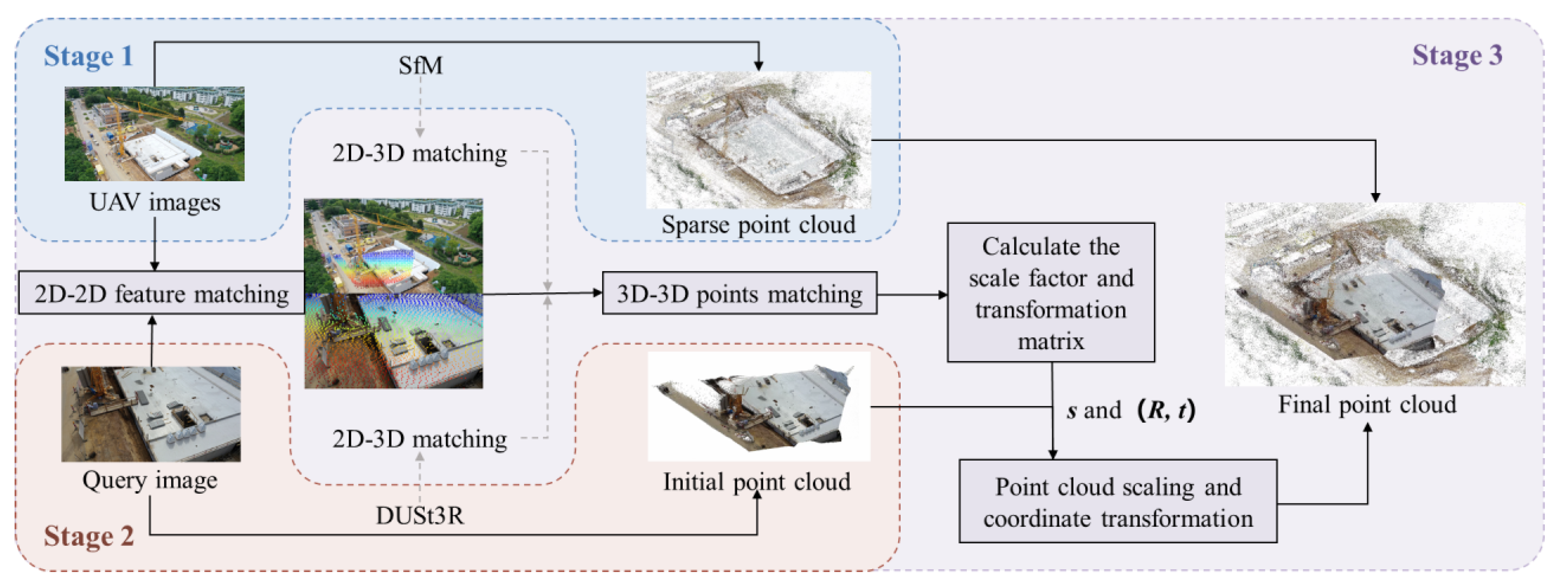
Figure 2.
Steps of sparse point cloud reconstruction.
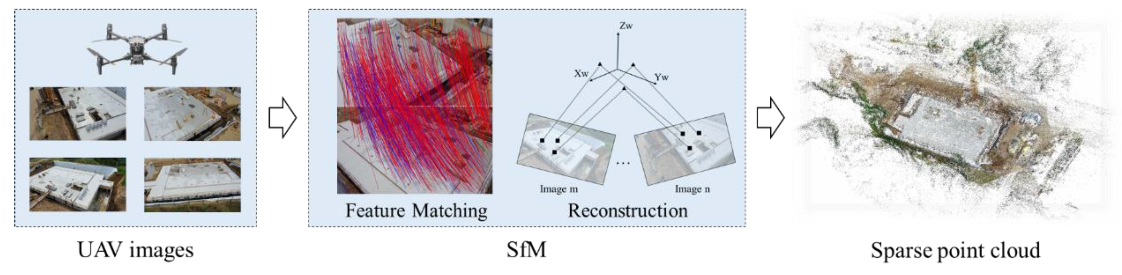
Figure 3.
DUSt3R framework.
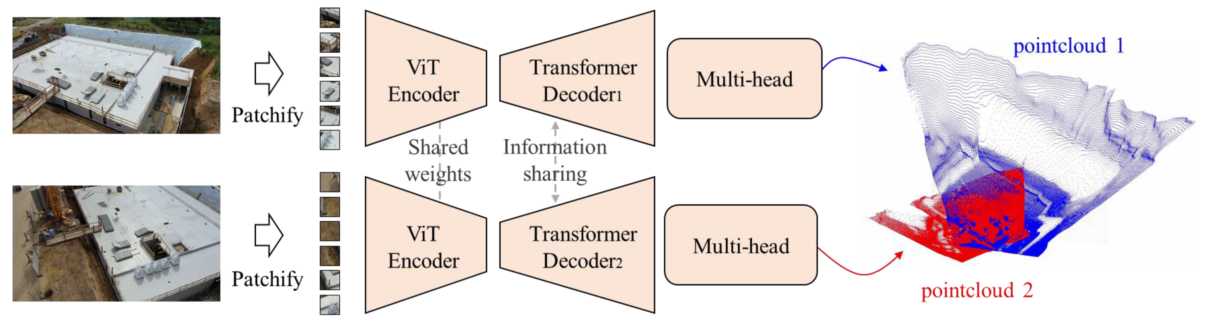
Figure 4.
Initial point cloud with dimensional differences from the conference point cloud.
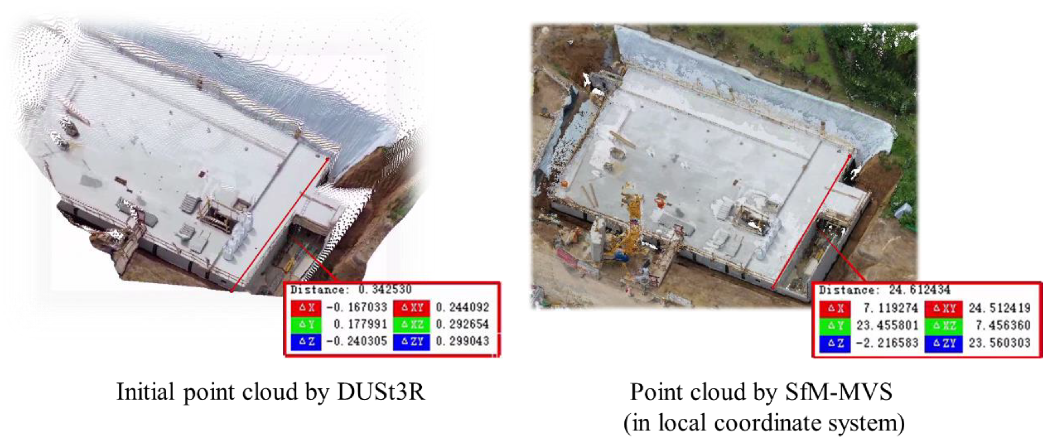
Figure 5.
Flowchart of the 2DFM-RANSAC.
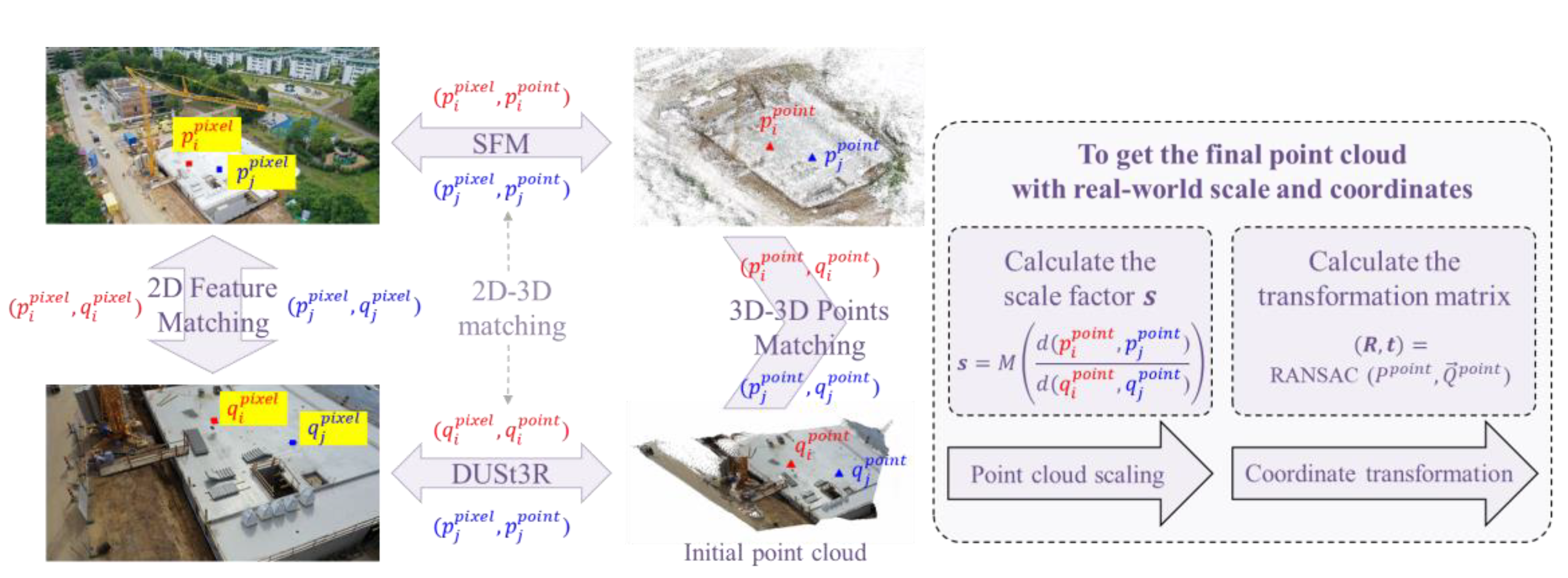
Figure 6.
2D feature point matching effect.
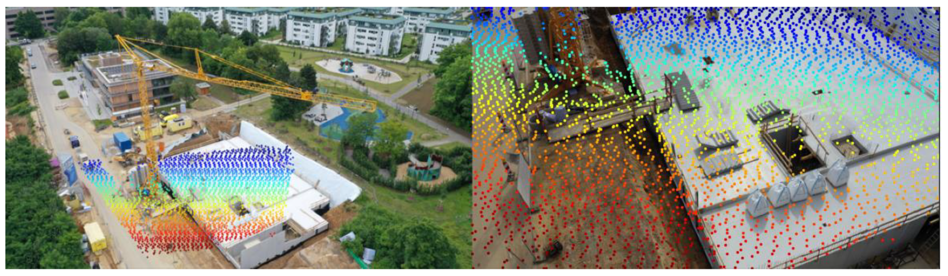
Figure 7.
The distribution of the calculated scaling factors, where the red line represents the median of the scale factor.
Figure 7.
The distribution of the calculated scaling factors, where the red line represents the median of the scale factor.
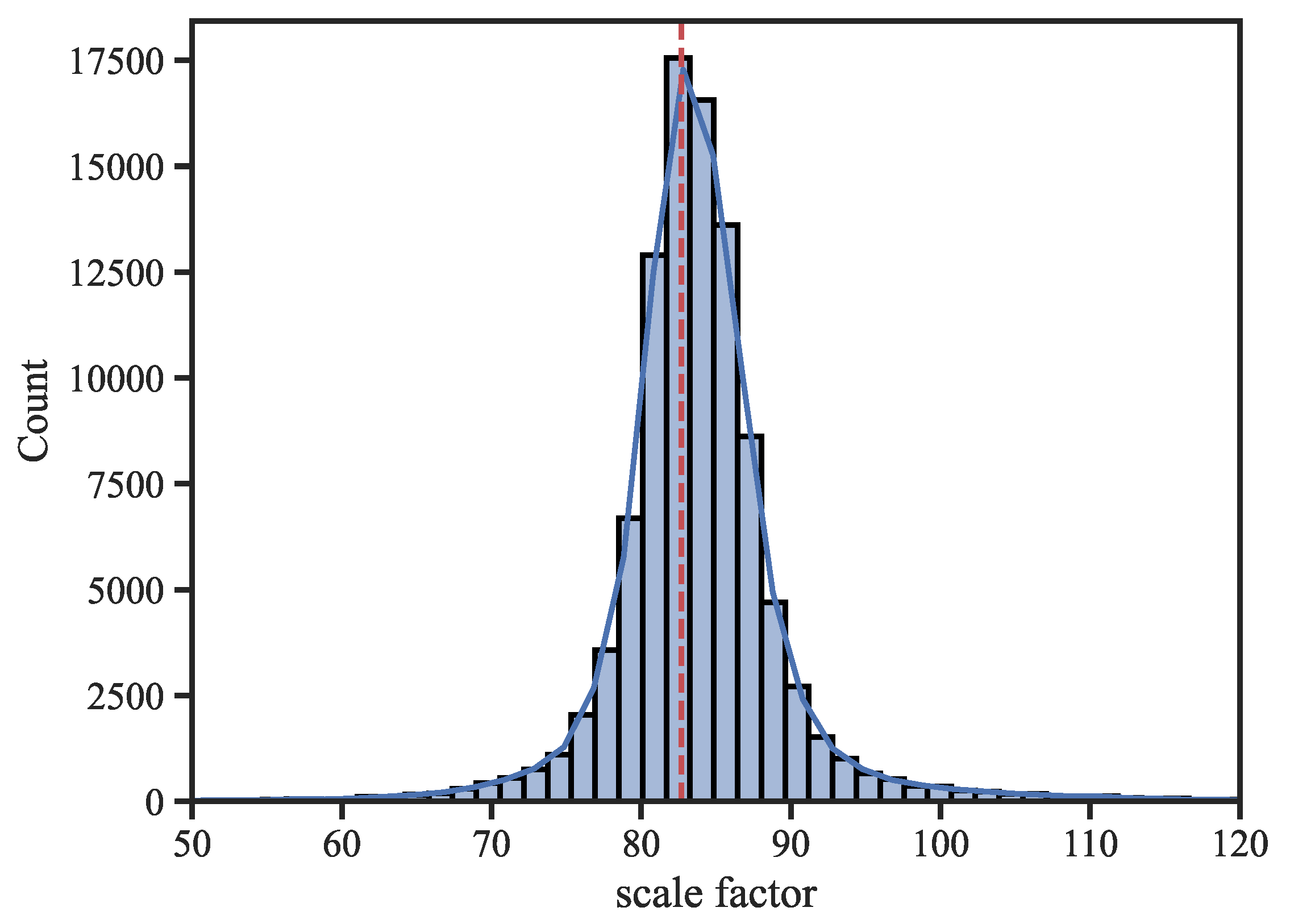
Figure 8.
Schematic diagrams of the experimental site: (a) the experimental site and the layout of surveillance cameras; (b) the digital orthophoto map of the experimental site; (c) the sparse point cloud of the experimental site obtained through oblique photography and SfM reconstruction.
Figure 8.
Schematic diagrams of the experimental site: (a) the experimental site and the layout of surveillance cameras; (b) the digital orthophoto map of the experimental site; (c) the sparse point cloud of the experimental site obtained through oblique photography and SfM reconstruction.
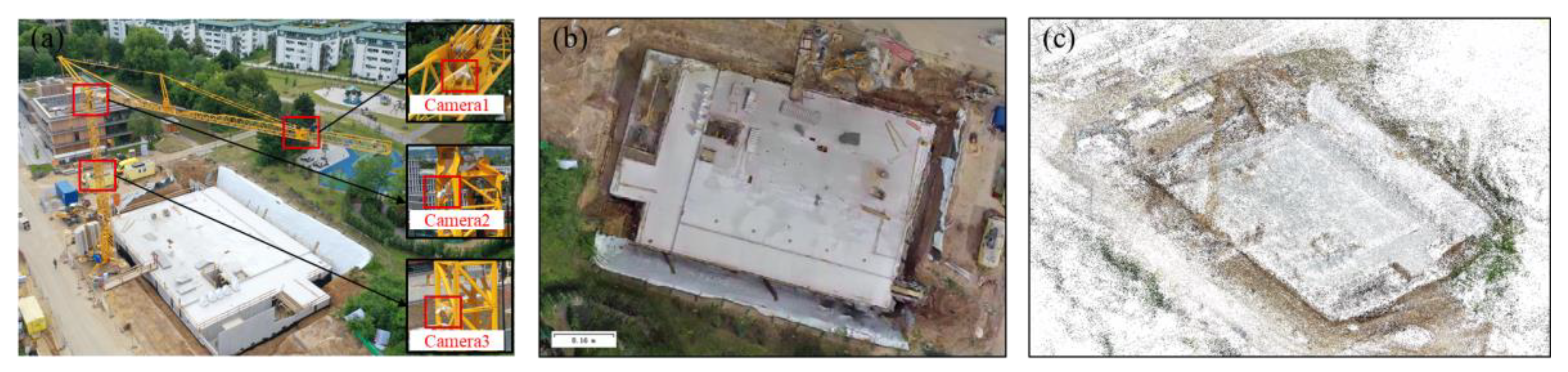
Figure 9.
Steps of point cloud error calculation.
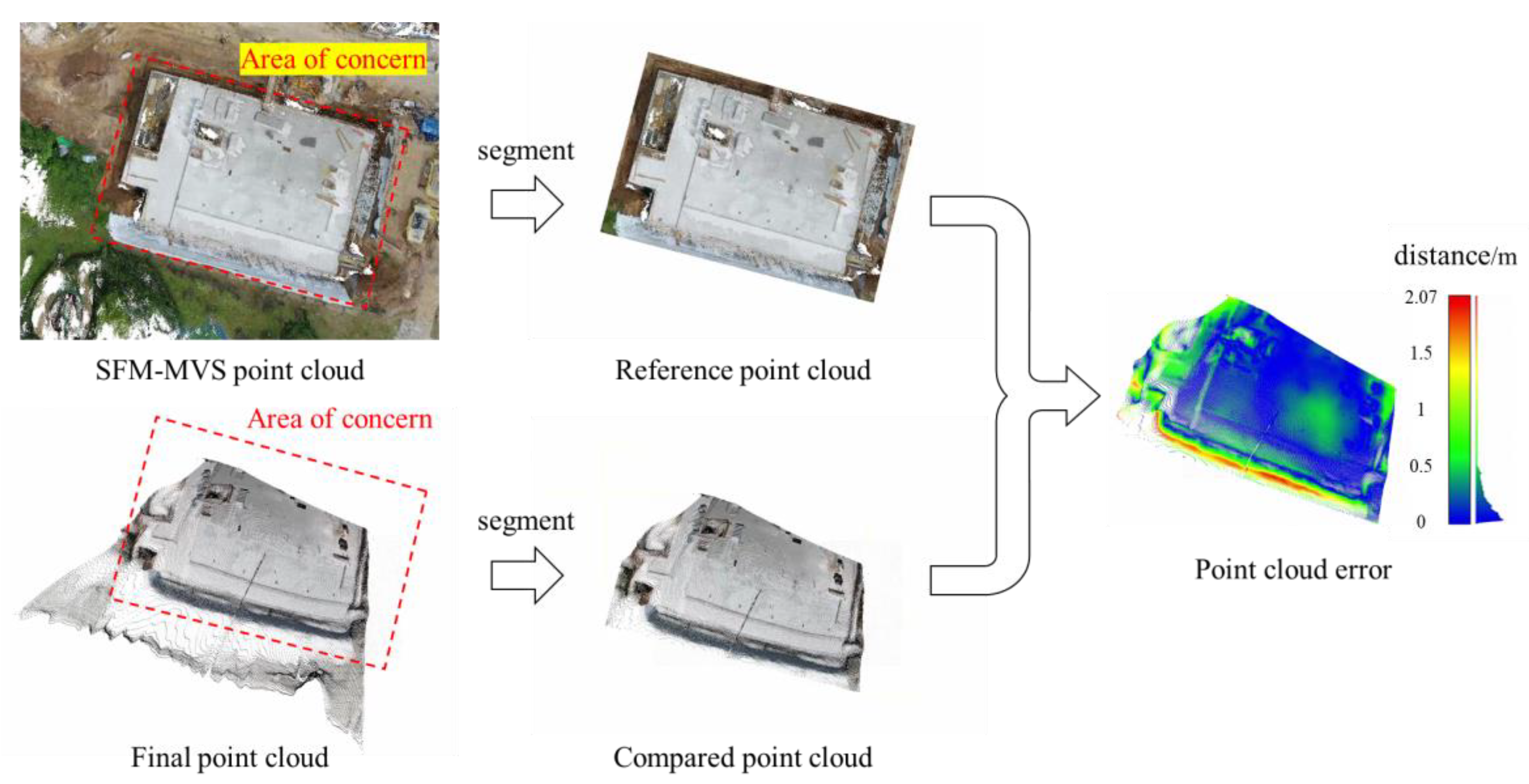
Figure 10.
Qualitative result of comparison experiment.
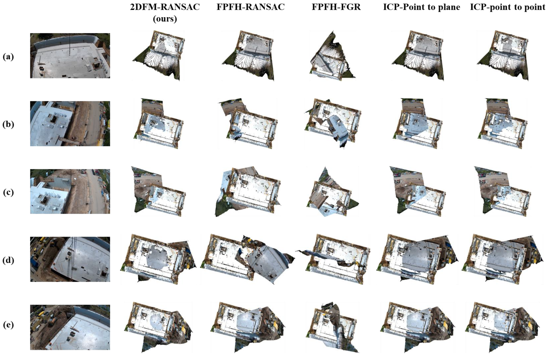
Figure 11.
Error distributions of different point cloud registration methods.
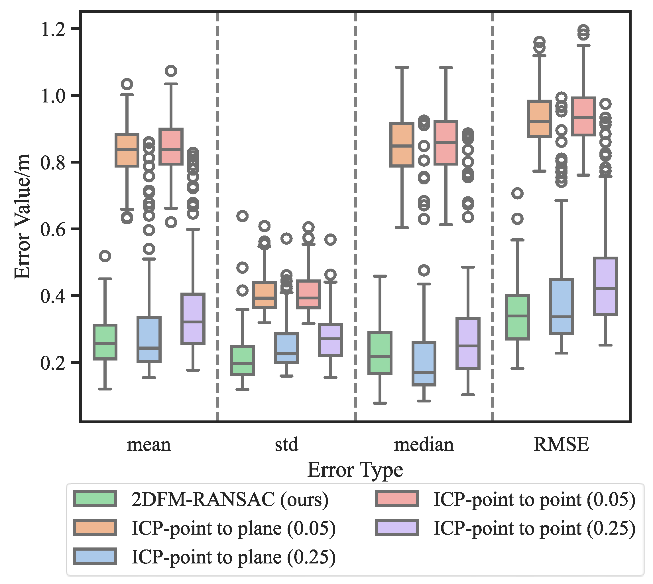
Figure 12.
Running time distribution of the initial point cloud reconstruction by DUSt3R.
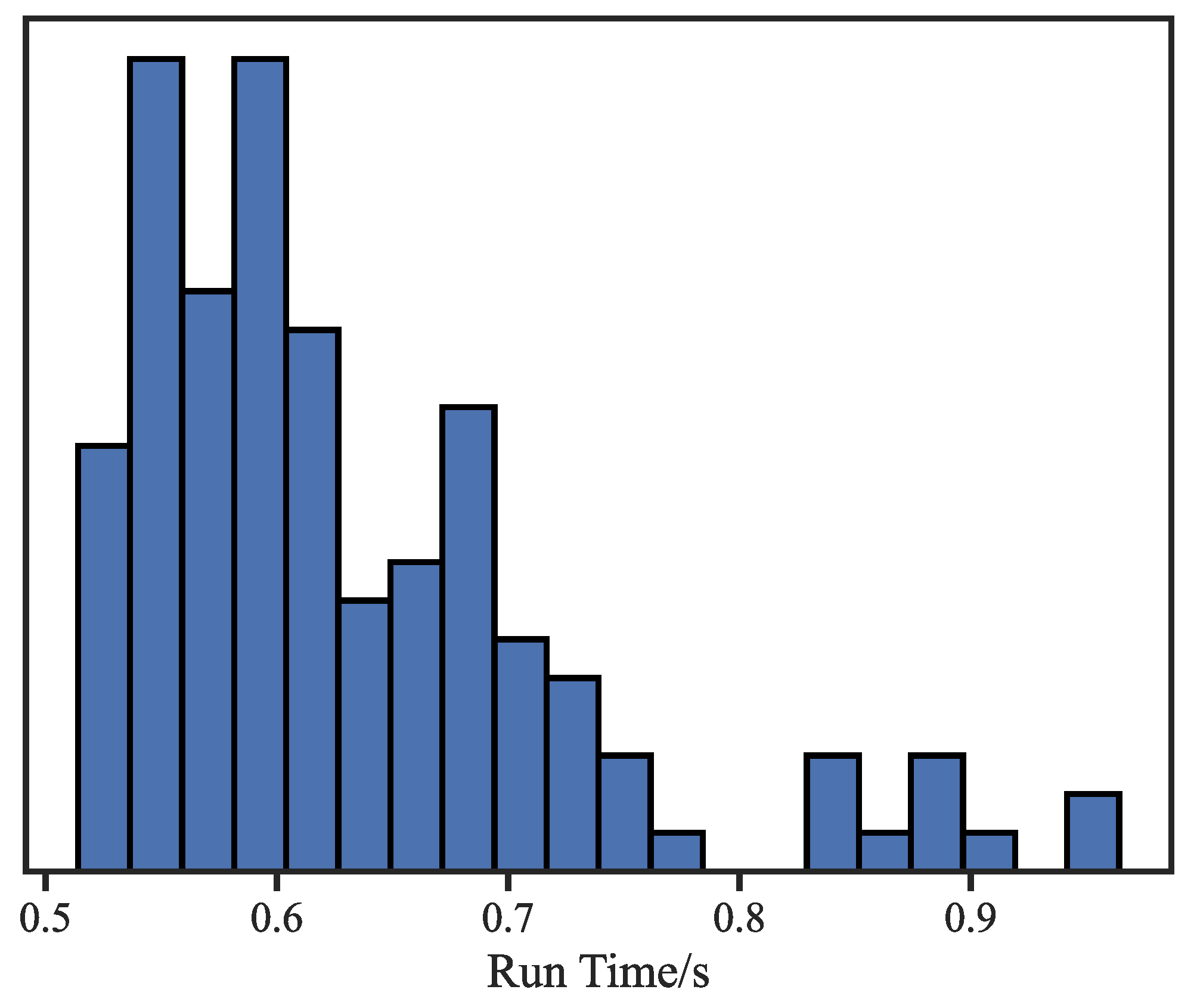
Figure 13.
Distribution of the calculation duration of different registration methods.
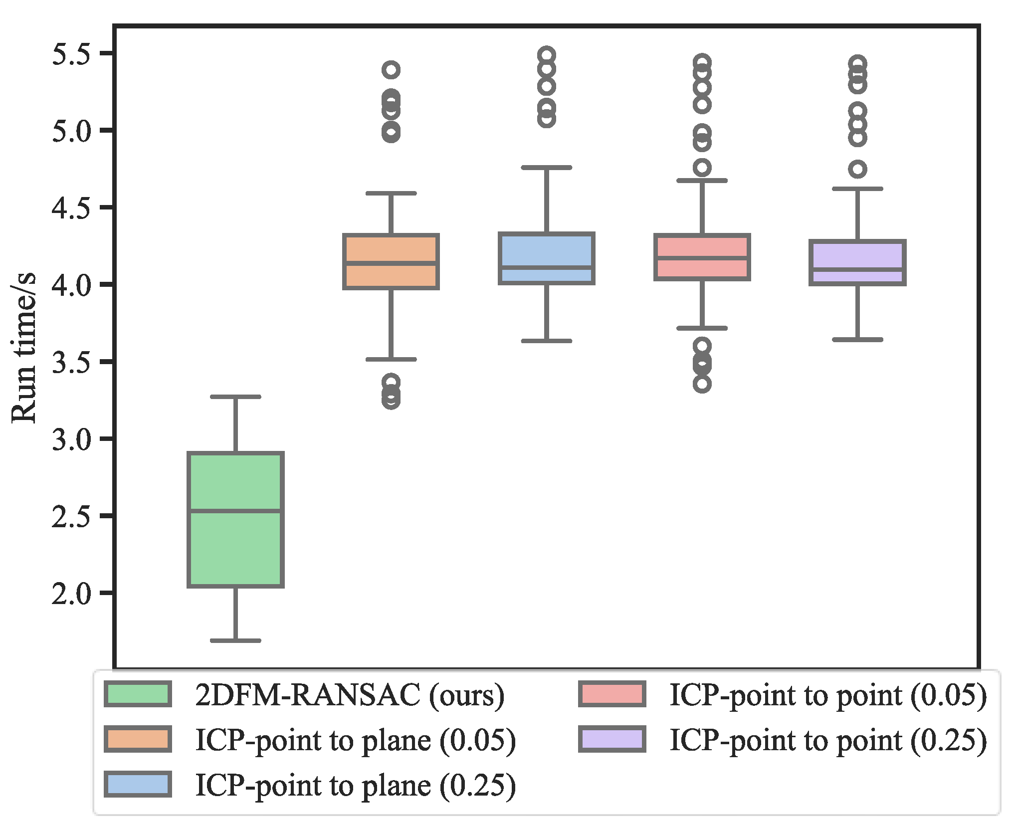

Table 1.
Results of different point cloud alignment methods.
| Need initial alignment | time/s | mean/m | std/m | median/m | RMSE/m | |
|---|---|---|---|---|---|---|
| FPFH-RANSAC | ✗ | 25.929 | 1.568 | 1.037 | 1.400 | 1.915 |
| FPFH-FGR | ✗ | 26.457 | 3.052 | 2.008 | 2.863 | 3.663 |
| ICP-point to plane (0.05) | ✓ | 4.163 | 0.837 | 0.408 | 0.849 | 0.933 |
| ICP-point to plane (0.25) | ✓ | 4.198 | 0.313 | 0.257 | 0.251 | 0.408 |
| ICP-point to point (0.05) | ✓ | 4.192 | 0.844 | 0.409 | 0.857 | 0.940 |
| ICP-point to point (0.25) | ✓ | 4.182 | 0.361 | 0.282 | 0.298 | 0.460 |
| 2DFM-RANSAC (ours) | ✗ | 2.474 | 0.268 | 0.230 | 0.220 | 0.358 |
Disclaimer/Publisher’s Note: The statements, opinions and data contained in all publications are solely those of the individual author(s) and contributor(s) and not of MDPI and/or the editor(s). MDPI and/or the editor(s) disclaim responsibility for any injury to people or property resulting from any ideas, methods, instructions or products referred to in the content. |
© 2025 by the authors. Licensee MDPI, Basel, Switzerland. This article is an open access article distributed under the terms and conditions of the Creative Commons Attribution (CC BY) license (http://creativecommons.org/licenses/by/4.0/).
Copyright: This open access article is published under a Creative Commons CC BY 4.0 license, which permit the free download, distribution, and reuse, provided that the author and preprint are cited in any reuse.


