
Submitted:
14 January 2025
Posted:
14 January 2025
You are already at the latest version
Abstract
The optimal viewpoint for monitoring robotic production processes is crucial for maintenance, inspection, and error handling, especially in large-scale production facilities, as it maximizes visual information. This paper presents a method for dynamic camera planning using an Unmanned Aerial Vehicle (UAV), enabling collision-free operation and measurable, high perspective coverage for a user-defined Region of Interest (ROI). Therefore, optimal viewpoints are searched with a greedy search algorithm and a decision for the optimal viewpoint is derived. The method is implemented within a simulation framework in Unity and evaluated in a robotic palletizing application. Results show that the use of an UAV as dynamic camera achieves up to twice the perspective coverage during continuous flight compared to the current capabilities of static cameras.
Keywords:
UAV
; View-Point-Selection
; model-based sensor planning
; dynamic sensor planning
1. Introduction
For robot-integrated manufacturing processes, such as handling, painting tasks or obstacle detection, it is essential that the process or product is inspected regularly to ensure process quality. The location of a camera to support the inspection should be chosen so that the camera image continuously maximizes the capture of visual information, is free from occlusion by scene objects and clearly shows the target object [1,2]. Methods for the selection of this viewpoint are referred to as camera planning and focus on the selection of an optimal viewpoint, which is to be chosen depending on the application, particular constraints of the camera or the scene and the temporal sequence of actions [3]. Within the field of cognition science, the decisive factors for maximizing visual information are well known, extensively discussed [4] and algorithmically abstracted for optimal viewpoints on objects [5]. The optimal viewpoint captures the object or situation completely, at a defined viewing angle, is free of visual obstacles and at a minimum distance from the object of interest, or Region of Interest (ROI) [6,7].
For the observation of robot-integrated processes, static camera systems are already widely used, whose position is defined once and which observe a ROI from a fixed perspective [8,9]. There are numerous approaches to this, within which the automatic generation of optimal viewpoints is already described, as in [9]. However, static cameras are limited in their perspective coverage, i.e., their ability to capture a ROI according to user specifications for relative image position and resolution. The reason for this is that the camera cannot be moved when the ROI is moved and can often only be adjusted by rotating, zooming or the support of multiple cameras [10,11]. Moreover, for covering all relevant positions comprehensively, static cameras need to be highly calibrated, might be expensive due to the amount of cameras and their installation is time-consuming [11]. However, for dynamic processes such as those that are increasing due to the growing use of mobile robotics, a static camera is often no longer sufficient and a camera must correspond to the dynamic nature of the process. Figure 1 illustrates typical robot-assisted processes in modern production systems, such as welding tasks on car chassis (Figure 1 (a)) and handling operations like picking components from conveyor belts or automated machines (Figure 1 (b)). In a welding task, a dynamic camera could track the welding tool to support error handling, visually inspect the welding result, or detect collisions between the manipulator and the environment. Similarly, in handling tasks (Figure 1b), visual support from a dynamic camera enables the recognition of gripped objects, evaluation of gripping positions and success, and detection of collisions in any production environment. Comparable work with static cameras requires several cameras in order to solve the spatial vision problem behind the grasping operation [11]. However, the use of a dynamic camera that can freely and independently move to any collision-free point within a robot cell poses several challenges. These include finding the optimal, occlusion- and collision-free viewpoint for the current handling situation and collision-free path planning to this viewpoint. In addition, situation-dependent challenges such as the speed of reorientation of the UAV due to sudden changes in the defined ROI or situations without a determinable optimal viewpoint must be considered.
To date, however, there are only a few works that present an application of a fully dynamic camera in a robot application. Rather, there are systems tailored to specific applications that guide a camera, or a system for AI image recognition is used that has been trained for state recognition from a static perspective [12]. What these systems lack is the complete dynamization of a camera, collision-free path planning between optimal viewpoints and a general method that allows safe cooperation between two robots whose workspaces overlap.
A new and particularly exciting approach in this context is the use of an Unmanned Aerial Vehicle (UAV) or multicopter as a dynamic camera, already described in [13]. UAVs offer ideal conditions, as they offer 6 degrees of freedom, are particularly maneuverable, and can be controlled using open-source frameworks with sufficiently path accuracy [14]. This approach stands out due to further consideration of coverage and collision problems as well as safety aspects in a robot cell. However, there are three fundamental questions that need to be answered to solve this challenge:
- How can the optimal viewpoint for any robot application be determined and evaluated?
- What methods can efficiently and accurately verify collision-free paths between two points in a continuous simulation?
- What is the optimal system configuration, including minimum distances and collision zones, for ensuring safe cooperation between UAVs and industrial robots?
To answer these questions, we implement our approach in Unity and evaluate it in two different robotic applications. Therefore, the technical requirements for an optimal viewpoint for a robot application are first compiled through a literature research within the chapter Related Works. Next, we present the conceptual framework for the technical implementation of the method in Unity. Finally, the results of the dynamic tracking of the optimal viewpoint are presented, discussed, and compared with the results of static cameras.
2. Related Works
2.1. Applications in Robot Vision Involving Dynamic Camera Planning
The optimal viewpoint for a robot task should maximize visually perceptible information through complete and unobstructed view on the relevant ROI in the robot cell. The effort involved should be minimal, e.g., the time and path length needed. The applications of dynamic camera planning are diverse and are, therefore, divided into the three application groups: Cinematography, Reconstruction & Inspection, and Teleoperation.
Cinematography: Cinematography describes the dynamic camera planning for filming and pays particular attention to the achievement of certain image compositions and the trajectory planning of the flight system. The trajectory is planned offline, as the scene and the actions performed are assumed to be known. Notable works can be found in [15,16,17].
Reconstruction & Inspection: In reconstruction and inspection, also known as reverse engineering, the aim is to fully capture a building model, for example, through three-dimensional scanning with a LIDAR sensor. To achieve this, the areas of a building are visually captured by an UAV’s onboard camera while optimizing the flight path for minimal length or duration, with the goal of achieving maximum coverage. The underlying planning problem is referred to as the next-best-view or view-planning problem. Challenges lie in deciding for the fewest possible viewpoints that cover entirely a target object or a scene and define an order in which the viewpoints are taken by the UAV. The viewpoints are determined from geometric model knowledge, within which characteristic points are either specified by the user or determined automatically. The literature searches in [18] and [19] provide a comprehensive overview of the work in this field. Of particular note is the work by Magana et al. in [20,21], which also holds a detailed literature review.
Teleoperation: In teleoperation, a user remotely controls a robot. The control is supported by a supplied camera image which offers an egocentric or exocentric view of the handling situation. The egocentric view provides a perspective from a fixed camera positioned on the robot itself, typically aligned with the robot’s own frame of reference. This viewpoint offers a direct, first-person perspective of the robot’s actions and immediate surroundings. In contrast, the exocentric view is positioned outside the robot system, offering a third-person perspective that captures the robot and its manipulation area from an external viewpoint. This external perspective allows for a broader overview of the robot’s interactions with its environment. The use of an additional camera image—whether egocentric or exocentric—is designed to enhance task performance by providing the user with critical visual information. This supplementary view supports better process monitoring and facilitates status recognition, enabling the identification of task progress, potential errors, or obstacles in the robot’s workspace. The literature review in [22] summarizes a comprehensive state of the art of teleoperation in robot applications. In the field of teleoperation, there are multiple studies that deal with the optimal viewpoint for certain processes, the reduction of a user’s cognitive workload or the measurability of support. An extensive literature review in [22] has compiled the existing work on the teleoperation of mobile robots. The authors in [23], for example, name the evaluation of manipulability, passability, accessibility and maneuverability as the relevant states in mobile robotics that can be resolved visually. In the case of manipulability an external viewpoint can be taken that detects the open gripper and the object to be handled in the lateral view and thus recognizes the relative position of the two subsystems [10,24]. This actively supports the successful gripping of an object. The navigation of a mobile robot, for example, can be supported by the top view of a mobile robot by distinguishing obstacles from available travel paths and identifying short paths to reach a target point [25]. For classic applications of industrial robotics, there are a variety of visual support possibilities, which are the tracking and readjustment of automated welding processes [26], inspection tasks [27], or in robot-integrated assembly and quality assurance [28]. However, there is currently no system that can determine the optimal viewpoint for a robot-assisted process and actively control a camera for tracking.
Regarding contributions from the field of teleoperation, these seem to be the closest to the target application envisaged here. For this reason, work that uses a flying robot for teleoperation is being investigated further.
2.2. Using a UAV as Dynamic Camera For Robot Tasks
The use of an UAV as a dynamic camera for the teleoperation of any robot is mentioned first in the work of Saakes et al. in 2013 [29]. For search and rescue missions, the authors show the potential of aerial images for reducing the collisions of teleoperated ground vehicles and the advantages for finding victims from a bird’s eye view. The UAV follows a marker attached to the vehicle and keeps a relative position to the vehicle. The aim of the paper is to evaluate the usefulness of third-person camera images for teleoperation. The authors evaluate their assumption in a user survey of the system. Despite the advantages of the flying camera in terms of clarity and flexibility, users note slow turns, instability and feeling uncomfortable when using the UAV as decisive factors for insufficient visual assistance.
This work is followed by the work of Claret et al. [30,31,32], in which the teleoperation of a mobile robot is supported by an UAV as a dynamic camera. The mobile robot is controlled via a haptic interface and an UAV moves in relation to the position of the mobile robot. As a safety and working area, the authors create a cylindrical envelope around the mobile robot that cannot be entered by the UAV. One focus of the authors’ contributions is avoiding occlusion by the robot’s joints during operation. For this purpose, the position of the UAV is set in relation to the joint positions and occlusion-free configurations of the robot are determined using the force field formulation. Unfortunately, the articles lack evaluations that examine practical use in corresponding scenarios. It is questionable whether the manipulation is restricted by adopting an axis configuration of the mobile robot to avoid occlusions and whether the actual control is disturbed as a result. In addition, it appears that there is a simpler way to determine visual occlusion of joints and volumes than the authors’ theoretical approach.
In their works, Xiao et al. [1,23,33] use an UAV as flying camera for the teleoperation of an Unmanned Ground Vehicle (UGV). The UAV is tethered to the UGV for power, so the papers are heavily concerned with accessibility and collision issues of the UAV and its tether with the environment. The authors develop a risk model for path planning, in which individual risks along a path are summed up and compared with achievable rewards. An ideal viewpoint of the UAV can, therefore, provide greater value than the potential risk posed by reaching the position would cost. The determination of the optimal viewpoint to be taken is based on the Gibsonian affordances from [34], which originate from human perception and user-studies. Although the authors conduct detailed experiments in interesting scenarios, relevant performance values for solving the tasks are not given. It is also unclear whether and how friction points of the tether with the environment affect the flight characteristics. Continuous flights around a robot, completely decoupled according to the definition of a dynamic camera, are unlikely. The flexibility of the UAV is extremely limited by the tether and is not a solution in environments with multiple collision volumes and interference contours. However, this is not the aim of the authors.
Another visual support for the teleoperation of a ground vehicle is considered by Gawel et al. [25] who provide a camera image from the top-down-view of a vehicle via an UAV. The UAV follows the ground vehicle at a fixed distance and height and moves in relative orientation to the vehicle during a turn or rotation so that the vehicle can be observed from a constant perspective viewpoint. The authors, though, did not consider collision problems of the UAV or the adoption of an optimal viewpoint.
Given our approach, the article by Senft et al. [35] is highly interesting. The authors use an UAV as a flying camera for the continuous tracking of a viewpoint, in this case, the end effector of the robot, and thus for teleoperation of the robot by a user. Therefore, they introduce a novel approach to address the challenge of providing adaptively minimally constrained camera views to support robot teleoperation, utilizing an UAV as dynamic camera. Their solution focuses on ensuring collision-free, unobstructed viewpoints with optimal viewing angles and distances between the camera and the target. They employ a weighted-sum nonlinear optimization approach to minimize a geometric cost function to calculate the commanded drone pose. Additionally, they utilize a second global viewpoint optimization process to generate alternate viewpoints and switch manually between them in case of occlusion or a better view. Their method demonstrates the ability to generate viewpoints required to support robot teleoperation and quickly switch between them. Although the authors present a promising approach, collisions, or perspective occlusions on the way to a new viewpoint are not considered. Also, according to our observations, it seems insufficient to determine only two optimal viewpoints per time segment, since several occlusion problems and obstacles between optimal viewpoints can arise in complex robot cells. Rather, the comparison of multiple optimal viewpoints and consideration of costs to change the viewpoint should also be part of an optimization method. In their evaluation, the authors implement their approach within a real-world application to observe a manipulation task. The user, though, must change manually between observing points. It is not fully clear if the user receives any information when to change the viewpoint and how the UAV is controlled to the next viewpoint. From the images it looks as if the UAV follows a pre-defined path or moves up first, than sideways to be above the next viewpoint and downwards, for reaching it. Our understanding is that to relieve the user of this task, a change of position should occur automatically, by the shortest route and with the least loss of visual information. It is also unclear to what extent multi-criteria optimization makes sense for a one-criteria optimization problem, as the only optimization target is the maximization of the perspective coverage. Due to the manual triggering of a positional change by an operator, the method presented is not completely autonomous.
2.3. Requirements for Visually Assisting Robot Applications With an UAV
Our literature review shows that none of the existing works fully meets the requirements for using an UAV as a dynamic camera to continuously and autonomously observe a ROI within a robot cell. Therefore, this paper presents a method and software implementation that enables an UAV to serve as a dynamic camera for any robot, in any workspace, and across a wide range of tasks. The main purpose is for teleoperation, providing process insight by monitoring any application, or conducting fault investigations. For the implementation within an industrial robot cell, the requirements from Table 1 are figured out after analyzing the literature and user expectations for an ideal dynamic camera.
Using our method, we determine the optimal camera viewpoint based on the positional relationship of a user-defined ROI within an industrial robot application. The optimization process identifies a viewpoint that ensures unobstructed observation of the ROI while maximizing visual information gain, considering potential UAV collisions with the robot or objects in the scene. Additionally, the method calculates multiple optimal viewpoints simultaneously, accounting for the UAV's switching costs between them. Thereby, the ROI is represented as a square area defined withing the camera frustum. In contrast to the work of other authors, the method presented is intended to allow the continuous adoption of the optimal viewpoint and, thus, the visual information acquisition achieved to be measured. This enables a final comparison of the perspective coverage of the UAV with the perspective coverage of static cameras.
3. Our Approach
For the development of our method, an initial implementation and validation is conducted in Unity. To enhance comprehensibility, Figure 2 visualizes key elements of the scene, including the robot’s workspace, collision space, and the collision-free movement space available to the UAV. The ROI is represented as a square area defined by the camera frustum, with the safety sphere at its center. This safety sphere, with radius , is excluded from path planning, and the UAV must immediately move out of it upon entry. The safety sphere serves not only to prevent collisions but also to maintain a target distance in real-world applications and to avoid entering the robot’s collision zone during rapid reorientation of the robot and ROI. Additionally, a capsule-shaped collider surrounds the robot’s axes, and a box collider encloses static scene objects, both acting as collision zones. The box collider is defined as the maximum bounding volume of static objects and must be avoided by the UAV.
3.1. Measurability of Perspective Coverage From Geometric Relationship
The method we propose for evaluating perspective coverage () is based on the ratio of the projected area of the region of interest () to the total area of the Near Clip Plane (). This value is related to the position of the given point is calculated for, written in . As shown in Figure 3, which represents the camera’s field of view, the scene is visualized through the camera frustum. The process begins with the manual definition of the ROI, which represents the area () the user aims to observe during operation. The user defines the dimensions of the ROI and specifies its parent object within the scene, relative to which the ROI moves. For example, in a robot-assisted welding process, the ROI can be visually positioned in front of the tool center point (TCP) of the welding device to ensure an optimal view into the process. Objects within the scene are projected onto the Near Clip Plane (NCP), which corresponds to the visible part of the camera’s view. The Far Clip Plane (FCP) marks the boundary of the camera’s visible field and determines the farthest objects visible from the camera’s perspective.
The area is defined by the height () and width () of the NCP and remains constant. The area , however, is calculated by first drawing lines from the UAV’s position () to each corner of the ROI and then determining the intersection points of these lines with the NCP. These intersection points are used to compute . In the context of a welding process, this method ensures that the TCP of the tool is clearly visible within the camera frustum, allowing for precise observation and evaluation of the process. Under the knowledge of and the distance of the NCP () from it, the four corner points of the NCP can be calculated as a vector of:
As visible in Figure 3, is created by the projected corner points from the corners of the ROI.
To determine , first form the linear equations with as the known point on the line and as the direction vector from to each corner, with the parameter to be found in the next step.
The plane can be defined by the plane equation , within which is the normal vector of the plane and is a constant.
Substituting the equation of the line into the equation of the plane gives the following result:
Solving the equation for yields the intersection points on the NCP when inserted into the linear equation:
Since the projected surface can be a quadrilateral due to the view from an oblique viewing angle, the surface is divided into two triangles. The addition of the areas then results in the projected area .
By determining from a geometric relationship, it is possible to evaluate the viewing point mathematically. The greater the value for , the better the ROI can be recognized in the camera view. This means that maximizing becomes the optimization target for an inserted camera viewpoint .
3.2. Finding Occlusion-Free Optimal Viewpoints
A suitable optimization method is selected by considering the underlying optimization problem and its requirements. For the highest , an optimal viewpoint is within a fixed distance (radius ) from the ROI, does not collide with the environment, and is showing the ROI without any occlusion. With the shortest possible distance to the ROI, potential viewpoints can be found using a search method that fulfills the given criteria and offers the highest value for in comparison to neighboring points. Our search space () can thus be written as . Colliders and their respective space () in the search space are described as , so that applies for collision−free points in space. For the simplified determination of the visibility of the ROI, it was defined that the UAV can rotate around the z-axis as desired and, thereby, can always look towards the ROI and keep it horizontally in the center of the FOV. This is possible with the real UAV as well, as it can turn at high speed and in any orientation to the actual direction of flight. From this it follows that the ROI is visible from the viewpoint when both are at the same height (). For the vertical visibility test, the condition was defined that the ROI must always be within the FOV. This relationship is visualized in Figure 4. The angle in Figure 4 is made up of the distance and the relative height difference () of the viewpoint. If the value of is smaller than the half of the , the viewpoint is visible.
To simplify the test, the camera is fictitiously positioned at the center point of the ROI and translated with an offset of in the direction of . The values and can be derived from the equations:
To summarize the most important findings and objectives for the optimization: The optimal position of a viewpoint maximizes the objective function , which is subject to several constraints. The mathematical formulation is as follows:
| Maximize: | |||
| Subject to: | 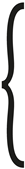 |
(The position lies within the defined operational area ) | |
| (The position lies outside restricted areas ) | |||
| (No occlusions are present at point ) | |||
| (The viewing angle remains within half the FOV) | |||
In here, the binary function for is indicating whether the viewpoint is obstructed by the obstacles () or visible (). If obstructed and not visible, the respective viewpoint is not considered as an optimal viewpoint. The objective function is thus continuous, with a local maximum resulting from the non-linear constraints such as collisions and occlusions. As a search algorithm hill climbing is chosen, due to its short search time needed, it is executed in parallel with a frequency of 10 Hz. Hill climbing is an optimization technique from the local search family, delivering suitable solutions within a comparatively short time frame without requiring detailed knowledge of the specific application. It is related to the gradient methods, which in turn originate from the greedy algorithms. This is an iterative, metaheuristic algorithm in which function values for a problem are tried out in a fixed adaptation of a function value. If a function value increases the current best value of the target function, the new function value is saved as local optimum. This process continues until no further improvement can be made or the termination criterion is reached. In our case, the termination criterion is defined as a maximum number of iterations of the hill climber without finding any viewpoint improving . For each iteration, the search step size changes, so that a variety of viewpoints in an area can be evaluated. Figure 5 shows a schematic representation of the program sequence using the hill climber algorithm. The green box contains the restrictions to be observed for a viewpoint.
However, since hill climbing only provides local maxima and the method for continuous comparison of optimal viewpoints is intended to compare several viewpoints with each other, potentially suitable starting points are determined on the basis of an investigation.
3.3. Starting Points for the Hill Climber
To define the starting viewpoint, values for are first examined for local maxima in order to determine the global minima and maxima around the ROI. The viewpoints are set to have a distance of radius from the ROI and, thereby, form a spherical shape around the ROI. Positions that are not within the FOV were neither calculated nor visualized. Figure 6 shows the result of the investigation of the minimum and maximum values of .
The perspective coverage decreases with a side view, meaning that converges to as the perspective rotates toward the side view of the ROI. Consequently, the global minimum is located at the exact side view. In contrast, the global maximum is found in a horizontal line that extends the normal of the plane, as indicated by the blue sphere in Figure 6. While this may initially seem intuitive, this can only be reached by eliminating the distortion of the projection of the ROI on the NCP (see Figure 7). By moving the ROI visually further to the edge of the NCP, the projected area maximizes and so does . This leads to finding the optimum for on the edge to where the ROI is visible from. For later use, these edge viewpoints have the drawback of placing the ROI at the edge of the camera image, which could be problematic in dynamic scenarios. In technical applications with slow movements, such as presence detection, this issue is less relevant. However, in faster-moving scenarios, the UAV’s inertia may prevent the camera from keeping the ROI fully centered, causing it to lose track of the ROI. For teleoperation tasks, this misalignment could also be uncomfortable, as a user wants to see an important object in the center of the screen.
The effect of distortion is well known for a central projection of an image on a plane and is visualized in Figure 7. The problem is part of radial distortion, in which points appear closer to the edge of the NCP with increasing distance from the center of the NCP in absolute distance and the calculation of a surface, as in our case, leads to an elongation of the surface or distortion of it. In the field of 3D computer graphics, the perspective, homogeneous transformation matrix of the points on the NCP is determined to compensate the distortion. However, since the rendered camera image is already available in Unity, the camera is considered ideal even without a calibration matrix and the projected points are determined by calculating the intersection points with the NCP. To normalize the size of the projected area, the distortion factor is calculated by the ratio of the distance from the point to the NCP center and the distance from point to the center of the projected ROI. Thereby, in equation (10), reflects the non-linear ratio of the increasing distortion if a point moves closer to the edge of the NCP.
The center point of the ROI is deliberately used for the calculation of , as the relatively small area on the ROI means that the deviation between the center point of the distorted area and the center point of the distorted edge lengths is negligible. With a precise calculation, however, even this center point would not be the arithmetic mean of the corner points. For therefore follows:
The effective area can be calculated from the projected area by:
For correct scaling of the area, it must be considered that the distortion is related to the square relationship of , and thus the height and width of the area. Both the height and the width of the plane are distorted as soon as the projected ROI is shifted from the center of the NCP. The calculated is thus applied three times in the result and is included in the result cubically. For it follows:
The investigation of the global maximum distributed around the ROI, as shown in Figure 6, provides the result that the highest perspective coverage of a viewpoint is to be expected with a frontal view and on a horizontal line to the ROI, also called the optical axis. Therefore, six starting points for the local search are chosen: one starting point per side of the ROI in extension to the plane normal of the ROI and two at an angle of ±45° in the horizontal center of the ROI. Figure 8 shows the positions for the starting points.
3.4. Collision Free Path Planning
Since a safety sphere encompasses the ROI, the shortest paths between opposite points inherently lie on the sphere’s surface. However, traditional path planning methods using sampling-based search algorithms like Rapidly-exploring Random Tree (RRT) or A-star (A*) present significant computational challenges in three-dimensional space, particularly for dynamic scenarios requiring rapid path computation [36]. Preliminary investigations revealed substantial limitations with sampling-based search methods: The computational effort is infeasible for real-time path planning, and the generated paths differ too much. Consequently, these path solutions induce unstable flight behaviors, characterized by frequent and abrupt directional changes [37]. To address these challenges, a hybrid approach was developed for determining movement paths on the safety sphere, based on tangent graph or geometric path planning, presented in [38] and [39]. With the tangent graph method, visible tangential lines between corners and faces of geometric primitives (e.g., circles, polygons, ellipses) can be planned as shortest paths and converted to a robot trajectory. These primitives represent obstacles in the environment. The approach combines elements of graph theory with geometric optimization to find an efficient, collision-free trajectory that is locally smooth and globally optimized. The use of visible tangents reduces the search space and makes the method computationally efficient. As previously mentioned, the primitive around which we actively plan a path is the sphere encompassing the ROI. The boxes and capsules, being collision zones outside our application, are excluded from active path planning in the initial step for simplification. Since we could not find a comparable approach by other authors using this method for path planning around a sphere, we present our approach in detail.
To derive path points on the sphere, we employ the Great-Circle Distance method, which calculates the shortest distance between two points on a spherical surface, also known as Orthodromic Distance [40]. The Great-Circle Distance defines the shortest path between two points on a spherical surface. This path lies within the plane formed by the starting point, the endpoint, and the center of the sphere (see Figure 9). The start point and end point are rotated using the plane’s normal vector to align with the XZ plane, effectively setting the y-coordinate to zero. Transforming both points to lie on the XZ plane offers a critical methodological advantage: it reduces a complex three-dimensional path-finding problem to a more manageable two-dimensional representation.
We consider scenarios where and may not directly intersect the safety sphere’s surface, but instead lie at a defined distance from its boundary, visible in Figure 10. In such cases, determining the shortest spherical path requires calculating the first tangential vector from to and the second vector from to . By leveraging and , which have been previously transformed to the XZ plane, we employ the Thales Circle method to derive these tangential vectors.
This geometric approach enables precise computation of the tangential points, facilitating accurate path planning for the UAV. First, the hypotenuses of the blue () and red () triangles are formed from the geometric relationships.
To obtain values for and , equation 15 is then converted to :
Substituting this into equation 16 and converted to results in:
For follows:
The variables and are then determined from the ratio of to multiplied by the vector of to :
The total distance is therefore made up of a linear length of the first tangential vector, the arc segment and the second linear length from the second tangential vector. The angle is between the vectors und .
Finally, the waypoints located on the linear paths can be interpolated with a specified segment length, while the waypoints on the arc segments can be systematically divided into discrete path segments, enabling precise waypoint generation for the UAV’s trajectory. By introducing a specified angular parameter , the angle from the points and to the X-axis is received:
A normalization of in the space of is given by:
The increment of the circle segments is then calculated using the specified number of circle segments :
For the calculation of the angle of the respective circle point it follows:
And for the circle points:
The -coordinate remains constant at zero, as the calculation is carried out in XZ planar space. The waypoints of the linear and of the arc segments are then, finally, rotated back to the starting rotation of .
After receiving the waypoints for travelling to a viewpoint, the collisions of the waypoints with the environment are analyzed. With the integrated method from the Bounds class in Unity, collisions are detected for box and capsule colliders in the scene. If any of the waypoints collide (), the respective viewpoint is discarded and no longer considered as a possible optimal viewpoint. For the collision-free waypoints, an average value of for all waypoints in a path is calculated, necessary for the selection of the optimal viewpoint in the next step. Waypoints, indexed with , from which the target is not visible or occluded, become . The following applies to the total number of path points :
The determination of occlusions of the ROI from a respective waypoint is carried out by ray casting from the corners and the center of the ROI to the respective viewpoint. Ray casting is carried out within the already implemented function of Unity.
3.5. Decision for the Optimal Viewpoint
The core of our method is the selection of the optimal viewpoint from the available ones and thereby follow a viewpoint to maximize . The basis for this is the availability of several viewpoints, which are in themselves a local optimum for and, thus, represent several options for an optimal viewpoint. The central selection criterion is the cost of reaching a viewpoint. An analytical approach is chosen, in which the value for the perspective coverage of a viewpoint for a given time segment is computed, written as . A value for is set to be 5 seconds, which is the maximum time to reach a viewpoint of largest path length in preliminary experiments for the UAV. Here, ∆t is split into two components: the dynamic portion , representing the time the UAV spends moving to the viewpoint, and the static portion , representing the time the UAV remains stationary at the viewpoint. While is multiplied with at the viewpoint, the dynamic component is multiplied by the average perspective coverage for the respective path. With this method, we get an approximated average coverage for the path considering the portion of changing and following a viewpoint in the application.
The determination of is based on the kinematic equations of motion for an acceleration of
±2.5 and a fixed maximum speed of 2 . The value for was determined in measurements and was found to be nearly constant for the maximum speed [14]. It should be noted that this is a strong simplification, which neglects dynamic forces, the time required for fine referencing at a viewpoint and also causing a delay, when leaving the planned trajectory. The consideration of these factors would exceed the scope of this work and is therefore considered for further development. By knowing the path length , the durations for can be calculated using common and known formulas.
From this consideration it follows that the viewpoint with the highest value for within the time interval also provides the highest perspective coverage. However, as viewpoints are sometimes found at the same local maxima, the flight time and perspective coverage are similar for the respective viewpoints and so is the value for . Small differences in , though, lead to unstable flight behavior, because the movement of direction and acceleration changes frequently as the position of the UAV changes. To select a stable viewpoint, a threshold method is implemented that provides stable selection of a viewpoint. The threshold method is designed to save the current viewpoint and only replaces it with the next viewpoint, if is 10 % greater than .
The current viewpoint is then given to the UAV controller. If no viewpoint is available, a safe position is given as to the UAV controller. The safe position is a manually defined static position above the robot (see Figure 11). Defining the safe position above the robot gives the decisive advantage for the UAV to return to a position from which many viewpoints can be reached. From above the robot, following the course of the spherical surface, there are presumably fewer collisions on paths and the UAV has a viewpoint available. However, this approach is probably unsuitable for complex cells, as collisions must always be expected even on paths to the safe position. The constant availability of a viewpoint and collision-free path planning is therefore the most essential element of our approach.
After selecting the optimal viewpoint, the corresponding waypoints are transferred to the UAV controller. The guidance logic relies on the waypoint hyperplane condition, a nonlinear method that ensures the UAV smoothly transitions between waypoints, introduced in [41]. This method works by specifying a target point, or lookahead point, from the determined waypoints. The lookahead point is the nearest point to the UAV with a distance greater than the specified lookahead distance . The specified ensures a smooth transition without abrupt directional changes for the UAV. If there is no waypoint with this distance, the viewpoint itself is approached directly.
3.6 Implementation of a State Machine
A state machine is implemented to ensure stable, predictable and safe flight behavior, even in situations with changing or temporarily unavailable viewpoints. This distinguishes between the states following, changing, hovering, and safe position. Through clearly defined input and output conditions for each state, the state machine ensures stable flight behavior of the UAV without abruptly changing the viewpoint or flight direction. Detailed explanations of the states can be found in Table 2.
4. Experimental Results and Discussion
To validate our method, two applications are implemented in Unity: a palletizing task and a welding application for a car body. Both tasks are common for industrial robots and hold significant challenges for UAV applications and, thereby, for receiving insight into dynamic robot processes within a dense environment and many obstacles. The ROI is manually defined by the user and linked to the position of the TCP, following the end effector of the robot. The robot’s joint data is sent to Unity via the RESTful API interface of the robot’s virtual controller, run in ABB RobotStudio. It is synchronized with the robot’s digital twin in Unity at 50 Hz. In addition to the UAV and the robot, the cell consists of manipulation objects (boxes), the ROI, and multiple box and capsule colliders. The colliders are assumed to have an offset of 40 centimeters from the colliding surface of the enclosing object, which seem to represent a realistic safety distance in an UAV application.
4.1. Results of the Palletizing Application
Figure 12 shows the static collision objects in the side (a) and top-down view (b) for the palletizing cell, showing the comparatively small movement space of the UAV and thus challenges for dynamic camera planning. The turquoise sphere holds the ROI in the center and describes the minimum distance of the UAV from the ROI. The purple capsule colliders form the protective volume of the robot and are also prohibited for the movement path of the UAV.
At the beginning of the routine, the UAV is placed at a location defined by the user. In our case, this is done in the entrance area of the cell visualized by a door, as there is sufficient space available. However, the starting location is irrelevant, as a similar orientation of the UAV in the cell and in tracking the optimal viewpoint is also evident after a short time for different starting locations. Starting the program, the light blue viewpoint is selected as the optimal viewpoint, which is in the optical axis of the ROI. In this application example, the choice for our take-off location merely shortens the time it takes to reach the light blue viewpoint. When placing the UAV on the other side of the ROI, our method will make the UAV switch to the side of the entrance, as the average score is higher and viewpoints here are not occluded by the conveyor belt. Figure 13 (a) shows a screenshot from the program sequence in which the UAV selects the light blue viewpoint and films from the desired perspective. It can be seen that the UAV stays in line with the optical axis of the ROI and moves along with it, as the robot palletizes boxes.
To compare the application results with traditional inspection solutions, four static cameras are attached to the fencing, as shown in Figure 14. The static cameras are parameterized identically to the camera of the UAV and thus offer a comparison of the perspective coverage. The locations of the static cameras are chosen to allow for the best possible view of the process with the least visual distortion due to an oblique view of the ROI, and at the smallest possible distance from the ROI. Thereby, they provide a meaningful comparison of the application results.
The result of our comparison is summarized in Table 3. With an average perspective coverage of 2.166 %, the UAV offers significantly higher perspective coverage than camera 1, which is the best camera in the scenario. As displayed in the following diagrams, the UAV is exclusively in the following state and there are no changes to other viewpoints or safe position states. Such a result can be classified as ideal, as continuously following a viewpoint results in the highest perspective coverage. Since there are no changes to other viewpoints or approaches to the safe position during the scenario, the UAV always achieves a view of the ROI. As a result, the perspective coverage is also the highest in this case. Although the percentage value of the average perspective coverage of around 2.166 % seems low, it should be noted that the actual size of visual areas on images in relation to the entire image size is deceptive. Figure 13 (b), therefore, shows the perspective on the ROI from the UAV’s viewpoint exemplary with the maximum theoretically coverage of 2.513 % under the given camera constraints and radius of the safety sphere.
Figure 15 illustrates the UAV’s increase and decrease of the perspective coverage, related to the control of the UAV, which steers the system to the position of the optimal viewpoint with a slight delay. While the UAV must be physically accelerated and decelerated, the viewpoint can beam to the next local maxima. As a result, the UAV always flies slightly behind the viewpoint and thus loses perspective coverage. It can also be seen that the viewpoint with the highest perspective coverage is not always the light blue viewpoint. However, since our method uses a threshold for decision making for choosing a viewpoint, slight differences of the perspective coverage do not lead to changing the viewpoint. Instead, the UAV remains at the light blue viewpoint. This can be seen in Figure 16.
Figure 16 shows a stable progression of the score with only minor changes over the entire routine. The light blue viewpoint is constantly selected as optimal viewpoint, which makes sense, looking at the application. This viewpoint is unoccluded and can be reached by the UAV at any time. Any viewpoint change would probably lower the perspective coverage. The results of the application show that for low and slow movement of the ROI, without occlusions and rotations of the ROI, the resulting dynamic camera planning of the UAV can be well implemented with our method. By analytically determining a score, viewpoints are evaluated in terms of their cost and the achievable perspective coverage, and a strategy can be determined for a given time window that compensates for small fluctuations in the highest perspective coverage and ensures stable perspective coverage.
4.2. Results of the Welding Application
Besides evaluating our approach in a palletizing application, we want to benchmark the approach in a way more complex welding application, presented in Figure 17. The welding application is designed in such a way that the TCP is moved along the chassis of the car body, visible in Figure 17 (b). The TCP starts at no. 1, at the front of the car, and follows the sequence of numbered contact points. Rotations of the ROI are performed at each contact point to set the rotation of the ROI to the displayed perspective and, thereby, cause the UAV to change the viewpoint. The rotation of the ROI is executed within Unity as soon as the robot reaches a contact point. Figure 17 (a) clearly shows that the UAV performing evasive movements to the safe position above the robot during flight. While the path of the UAV in the car’s front area only differs slightly, the path in the area of the vehicle’s door deviates significantly, and the UAV’s movement seems uncontrolled.
As shown in the following diagrams, the UAV loses the optimal viewpoint at contact point no. 4 because it cannot respond quickly enough. At this point, our method outputs an optimal viewpoint above the car’s roof. Consequently, the UAV must perform a significant reorientation, moving from a position beside the robot to a position above the car’s roof to avoid colliding with the robot arm. However, since the direct and shortest path passes through the capsule collider, the UAV cannot find a feasible route and instead switches to the safe position state. This behavior can be observed in Figure 17 (a), where the vertical flight path above the robot indicates the UAV’s movement to the safe position. Since there is no feedback mechanism to inform the robot whether the UAV has reached the designated viewpoint, the robot proceeds to contact point no. 5 without waiting for the UAV. As a result, the optimal viewpoint cannot be reached, causing the UAV to oscillate between different viewpoints and repeatedly return to the safe position. This behavior significantly disrupts the UAV’s flight performance due to the inaccessibility of the target position and the relatively rapid reorientation required. The UAV struggles to reach the viewpoint quickly enough, which severely impairs its overall effectiveness.
Table 4 shows the results for the application. With an average perspective coverage of 1.667 % the UAV gains sight on the ROI. Compared to the static cameras installed on the fencing, this is still an acceptable result. The big difference between the perspective coverage of the UAV and the static cameras is due to the relatively large distance of the static cameras to the ROI. These are attached to the more distant fencing. It could certainly be discussed whether real cameras would be equipped with a lens and a corresponding zoom for this case to capture the scene with a higher perspective coverage despite their greater distance.
The evaluation of the perspective coverage in Figure 18 visualizes two segments of about 5 and 12 seconds without any sight on the ROI. With constant high perspective coverage, the UAV can initially follow the ROI at the light blue viewpoint and loses sight of the ROI at about 20 seconds with a change to the violet position. Only after approximately 45 seconds the UAV regains perspective coverage and, thus, switches to following state and regains sight on the ROI.
The areas without perspective coverage can be found congruently in Figure 19. Inhere, frequent changes of the optimal viewpoint mark an unstable flight behavior as the system does not constantly decide for a viewpoint and leads to frequent changes of movement direction and, ultimately, to a safe position state. Jumps from second ~22 from the light viewpoint to the violet viewpoint, to the blue viewpoint and back are evidence of erratic flight behavior, which, as already explained, is reflected in the perspective coverage. Black segments in the timeline of Figure 19 indicate that no viewpoint was available at this time and the safe position is approached.
Figure 20 provides an additional overview of the resulting score from 22 to 40 seconds in addition to the display of the respective state for determining the scores of all viewpoints. This occurs even though the perspective coverage in this range is high for all viewpoints and the viewpoints are all available (). Waypoints may overlap with the environment or, in our case, with the robot’s capsule collider. This issue arises when the UAV cannot find a viable path from its current position to any of the defined viewpoints.
To sum up the findings for our method’s implementation, the defined target requirements (see Table 1) are largely fulfilled. The implementation conducted in Unity already shows a satisfactory result for perspective coverage for the palletizing application. The measurability of the method in terms of measurable perspective coverage over time means that solid statements can be made about the effectiveness of the method. The hill climber method used for the search of local optima can efficiently find the optimal viewpoint even in the case of larger step sizes of the algorithm. In the welding application in particular, the starting points of the viewpoints are often obscured by the car body. As a result, collision-free and occlusion-free viewpoints above the body are successfully identified. The path planning method for the UAV described by us has proven to be very promising for the application, as a path can be found time efficiently, without sudden changes in direction and taking collisions into account. The determination of a constant shortest path is particularly important for the application in order to avoid changes in the direction of movement due to changing paths.
After extensive analysis, our method for calculating the score provides comprehensible decision features for a specified time window despite its simplicity. By defining the score for a time window and a threshold, a stable decision behavior for the optimal viewpoint can be observed. The behavior of the UAV is finally supported by the implementation of the state machine. Within the conducted experiments it can be concluded, that the definition of a safe position and the specification of states contribute significantly to the dynamic camera planning.
4.3. Limitations and Future Work
Nevertheless, the limitations of our method are shown in the welding application. The greatest influence on perspective coverage is exerted by flights to the safe position, which occur when no available viewpoint can be determined for the UAV. When approaching the safe position, the UAV completely loses sight of the ROI. We initially assumed the placement of the safe position above the robot to ensure that a position is assumed from which the UAV can free itself from a situation in which it is stuck, for example. Depending on the application, however, it might be worth considering moving the safe position to a position outside the robot’s workspace that is at the same height as the ROI. This gives the advantage of observing the ROI from the UAV’s position even if a safe position state is triggered. Therefore, the safe position must be cleverly selected and reachable depending on the application at minimal cost.
Since the hovering state is triggered if no path to a viewpoint is available, it could be an effective solution to extend the implemented path search around the sphere with additional section planes. By using our score method, multiple optional paths could then be compared by the highest average perspective coverage. In this way, it is more likely to find an available path that may even have a higher score than the path of the great circle distance. It would also be interesting to extend the path search for other geometric primitives, such as the box colliders or the capsule colliders of the robot.
In addition to improving the handling of the safe position state, the application highlights the importance of minimizing sudden, short-term changes of movement direction of the UAV. A sudden change of movement direction with a strong acceleration rotates the system. This can briefly cause the ROI to leave the field of view and, furthermore, negatively affect flight stability, compromising visual continuity and the operator’s ability to maintain clear sight. Ensuring a stable and steady camera movement is therefore crucial for achieving optimal performance.
In addition to the suggestions already mentioned for improving the application, we consider the continuation of our work through the implementation of a method for future knowledge of the application to be one of the greatest potentials. Currently, the viewpoint with the highest score and an added threshold value is always taken in accordance with our greedy strategy. This does not consider the fact that an optimal viewpoint, even if it has a high score at that moment, only exists for a brief moment. This circumstance results in fundamental problems for applications such as the welding application:
- If the viewpoint disappears shortly after the UAV changes to the change state without having been reached by the UAV, the theoretical perspective coverage calculated in the score will not be achieved.
- The UAV could reach a point in the routine where suddenly no other viewpoint is available and it get stuck.
- The UAV does not recognize a change to a viewpoint that is worse at this point, but which will provide a higher perspective coverage in the future.
These challenges could be addressed by incorporating future knowledge of the robot’s position, the ROI, optimal viewpoints, and potential collisions. By predicting the optimal viewpoints and their perspective coverage at specific points in the robot’s routine, it would be possible to devise a flight path strategy that maximizes perspective coverage when executed by the UAV. This approach would also account for the time required to adjust the viewpoint and the temporary loss of coverage during transitions. As part of our future work, we plan to develop and implement a method that integrates this predictive knowledge into the UAV’s dynamic planning process.
5. Conclusions
Robot-integrated production processes often occur in enclosed areas that are inaccessible to operators. The ability to monitor these processes—whether for teleoperation, maintenance, repair, or troubleshooting—without interrupting production is therefore of significant interest. To address this challenge a method was developed to determine, evaluate, and control an UAV to operate as a dynamic camera from a changing optimal viewpoint. An optimal viewpoint is free of occlusions, avoiding collisions and providing the maximum perspective coverage. Starting the search from six predefined positions distributed around the ROI, a hill-climbing algorithm searches for a locally optimal viewpoint. The shortest paths to these viewpoints are calculated continuously, following the orthodrome (the shortest path on the surface of the safety sphere). These waypoints are then verified to be collision-free. If a waypoint passes this check, a score is assigned to the corresponding viewpoint, which evaluates the perspective coverage achieved at, and on the path to this viewpoint. Comparing multiple viewpoints as an alternative, a viewpoint change is triggered when an alternative viewpoint achieves a score at least 10% higher than the current one. Additionally, to ensure smoother transitions and decision-making, a state machine is implemented to control the UAV. This state machine stabilizes transitions between states and prevents abrupt changes in the UAV’s behavior, ensuring reliable and predictable operation.
The evaluation of our method within a palletizing and a welding scenario suggests a significant increase in process insight using an UAV as a dynamic camera. However, the perspective coverage of the UAV is strongly related to the number of viewpoint changes and the number of safe position flights, as shown in the welding scenario. If the viewpoint is changed, the perspective coverage is temporarily reduced. In the case of a safe position state, however, the UAV’s does not gain any perspective coverage for our selected system setup.
We have discussed several proposals to reduce this form of interruption and thus reduce the number of safe position states. In such situations, the UAV might move to a viewpoint that becomes unavailable unexpectedly or stays in a position from which it cannot reach other viewpoints identified by our previously implemented path search. To reduce this behavior, the biggest advantage seems to be the inclusion of future knowledge for robot-integrated processes and pre-planning a flight. In this regard, robot-integrated processes can include both purely cyclical scenarios and acyclic scenarios with recurring motion patterns. It can be assumed that robot applications have at least partially recurring movement patterns, e.g., when performing certain actions such as tool changes, or moving the TCP along identical paths. Identifying similarities from these behaviors and influencing future UAV control might lead to a huge improvement in dynamic camera planning.
To address these challenges, dynamic adaptability in path planning is critical. This includes the ability to predict task-specific demands and adjust the UAV’s trajectory in real-time, ensuring continuous operation even in the presence of unforeseen collisions or occlusions. Future systems should leverage predictive algorithms and empirical data, such as past cycle patterns or event frequencies, to support the selection of optimal viewpoints with minimal changes and error states. The developed methods must be evaluated in diverse application scenarios, particularly those involving frequent reorientations of the ROI and significant UAV realignments due to changing viewpoints. Additionally, scenarios should include previously unconsidered situations with potential collision risks or other critical error states to thoroughly evaluate the program logic. By addressing these challenges, such systems will not only enhance operational efficiency but also ensure robust and flexible robot-integrated processes suitable for real-world deployment.
Author Contributions
M.B. is the corresponding author, responsible for the basic concepts, literature review, implementation, and discussing of results. B.K. is the active provider of the underlying ideas and advice, also responsible for revising the manuscript. P.K. is a former student of M.B. and supported in the implementation process. All authors have read and agreed to the final version of the manuscript.
Funding
This research received no external funding.
Data Availability Statement
The raw data supporting the conclusions of this article will be made available by the authors on request.
Conflicts of Interest
The authors declare no conflicts of interest.
References
- Xiao X, Dufek J, Murphy RR (2020) Tethered Aerial Visual Assistance.
- Gonzalez-Barbosa J-J, Garcia-Ramirez T, Salas J, Hurtado-Ramos J-B, Rico-Jimenez J-J (2009) Optimal camera placement for total coverage. In: 2009 IEEE International Conference on Robotics and Automation. IEEE, pp 844–848. [CrossRef]
- Christie, Marc and Machap, Rumesh and Normand, Jean-Marie and Olivier, Patrick and Pickering, Jonathan (2005) Virtual Camera Planning: A Survey. In: Butz, Andreas and Fisher, Brian and Krüger, Antonio and Olivier, Patrick (ed) Smart Graphics.
- Kaiser D, Quek GL, Cichy RM, Peelen MV (2019) Object Vision in a Structured World. Trends Cogn Sci 23:672–685. [CrossRef]
- Rudoy D, Zelnik-Manor L (2012) Viewpoint Selection for Human Actions. Int J Comput Vis 97:243–254. [CrossRef]
- Bares WH, Thainimit S, McDermott S (2000) A Model for Constraint-Based Camera Planning. In: AAAI Press (ed) Smart Graphics, Papers from the 2000 AAAI Spring Symposium, pp 84–91.
- Nicolas Halper, Patrick L. Olivier (2000) CamPlan: A Camera Planning Agent. In: AAAI Press (ed) Smart Graphics, Papers from the 2000 AAAI Spring Symposium, pp 92–100.
- Triggs B, Laugier C (1995) Automatic camera placement for robot vision tasks. In: Proceedings of 1995 IEEE International Conference on Robotics and Automation. IEEE, pp 1732–1737. [CrossRef]
- Baumgärtner J, Bertschinger B, Hoffmann K, Puchta A, Sawodny O, Reichelt S, Fleischer J (2023) Camera Placement Optimization for a Novel Modular Robot Tracking System. In: 2023 IEEE SENSORS. IEEE, pp 1–4. [CrossRef]
- Jangir R, Hansen N, Ghosal S, Jain M, Wang X (2022) Look Closer: Bridging Egocentric and Third-Person Views With Transformers for Robotic Manipulation. IEEE Robot Autom Lett 7:3046–3053. [CrossRef]
- Akinola I, Varley J, Kalashnikov D (2020) Learning Precise 3D Manipulation from Multiple Uncalibrated Cameras. In: 2020 IEEE International Conference on Robotics and Automation (ICRA), pp 4616–4622. [CrossRef]
- Singh A, Kalaichelvi V, Karthikeyan R (2022) A survey on vision guided robotic systems with intelligent control strategies for autonomous tasks. Cogent Engineering 9. [CrossRef]
- Boshoff M, Kuhlenkötter B, Jakschik M, Sinnemann J (2022) Dynamische Kameraverfolgung von Regions of Interest in der Produktion mit Flugrobotern. Zeitschrift für wirtschaftlichen Fabrikbetrieb 117:733–736. [CrossRef]
- Boshoff M, Barros G, Kuhlenkötter B (2024) Performance measurement of unmanned aerial vehicles to suit industrial applications. Prod Eng Res Devel. [CrossRef]
- Alcántara A, Capitán J, Cunha R, Ollero A (2021) Optimal Trajectory Planning for Cinematography with Multiple Unmanned Aerial Vehicles. Robotics and Autonomous Systems 140:103778. [CrossRef]
- Pueyo P, Cristofalo E, Montijano E, Schwager M (2020) CinemAirSim: A Camera-Realistic Robotics Simulator for Cinematographic Purposes. In: 2020 IEEE/RSJ International Conference on Intelligent Robots and Systems (IROS). IEEE, pp 1186–1191. [CrossRef]
- Bonatti R, Wang W, Ho C, Ahuja A, Gschwindt M, Camci E, Kayacan E, Choudhury S, Scherer S (2019) Autonomous aerial cinematography in unstructured environments with learned artistic decision-making. [CrossRef]
- Peuzin-Jubert M, Polette A, Nozais D, Mari J-L, Pernot J-P (2021) Survey on the View Planning Problem for Reverse Engineering and Automated Control Applications. Computer-Aided Design 141:103094. [CrossRef]
- Zeng R, Wen Y, Zhao W, Liu Y-J (2020) View planning in robot active vision: A survey of systems, algorithms, and applications. Comp Visual Media 6:225–245. [CrossRef]
- Magaña A, Dirr J, Bauer P, Reinhart G (2023) Viewpoint Generation Using Feature-Based Constrained Spaces for Robot Vision Systems. Robotics 12:108. [CrossRef]
- Magana A, Gebel S, Bauer P, Reinhart G (2020) Knowledge-Based Service-Oriented System for the Automated Programming of Robot-Based Inspection Systems: Technical University of Vienna, Vienna, Austria, 08-01120 : proceedings. IEEE, Piscataway, NJ. 20 September. [CrossRef]
- Moniruzzaman MD, Rassau A, Chai D, Islam SMS (2022) Teleoperation methods and enhancement techniques for mobile robots: A comprehensive survey. Robotics and Autonomous Systems 150:103973. [CrossRef]
- Xiao X, Dufek J, Murphy RR Autonomous Visual Assistance for Robot Operations Using a Tethered UAV 16:15–29. [CrossRef]
- Sato R, Kamezaki M, Niuchi S, Sugano S, Iwata H (2019) Derivation of an Optimum and Allowable Range of Pan and Tilt Angles in External Sideway Views for Grasping and Placing Tasks in Unmanned Construction Based on Human Object Recognition. In: 2019 IEEE/SICE International Symposium on System Integration (SII). IEEE, pp 776–781. [CrossRef]
- Gawel A, Lin Y, Koutros T, Siegwart R, Cadena C (2018) Aerial-Ground collaborative sensing: Third-Person view for teleoperation. In: 2018 IEEE International Symposium on Safety, Security, and Rescue Robotics (SSRR), pp 1–7. [CrossRef]
- Haldankar T, Kedia S, Panchmatia R, Parmar D, Sawant D (2021) Review of Implementation of Vision Systems in Robotic Welding. In: 2021 5th International Conference on Intelligent Computing and Control Systems (ICICCS). IEEE, pp 692–700. [CrossRef]
- Glorieux E, Franciosa P, Ceglarek D (2020) Coverage path planning with targetted viewpoint sampling for robotic free-form surface inspection. Robotics and Computer-Integrated Manufacturing 61:101843. [CrossRef]
- Herakovic N (2010) Robot Vision in Industrial Assembly and Quality Control Processes. In: Ales Ude (ed) Robot Vision. IntechOpen, Rijeka. [CrossRef]
- Saakes D, Choudhary V, Sakamoto D, Inami M, Lgarashi T (2013) A teleoperating interface for ground vehicles using autonomous flying cameras. In: 2013 23rd International Conference on Artificial Reality and Telexistence (ICAT). IEEE, pp 13–19. [CrossRef]
- Claret J-A, Zaplana I, Basanez L (2016) Teleoperating a mobile manipulator and a free-flying camera from a single haptic device. In: 2016 IEEE International Symposium on Safety, Security, and Rescue Robotics (SSRR). IEEE, pp 291–296. [CrossRef]
- Claret J-A, Basañez L (2017) Using an UAV to guide the teleoperation of a mobile manipulator. In: XXXVIII Jornadas de Automática: Gijón, 6, 7, y 8 de septiembre de 2017. Universidade da Coruña. Servizo de Publicacións, pp 694–700. [CrossRef]
- Claret J-A, Basañez L (2019) Teleoperating a mobile manipulation using a UAV camera without robot self-occlusions. XL Jornadas de Automática: libro de actas 694–701. [CrossRef]
- Xiao X, Dufek J, Murphy R (2017) Visual servoing for teleoperation using a tethered UAV: The 15th IEEE International Symposium on Safety, Security and Rescue Robotics : Oct 11-13, 2017, Shanghai, China. IEEE, Piscataway, NJ. [CrossRef]
- Dufek J, Xiao X, Murphy RR (2021) Best Viewpoints for External Robots or Sensors Assisting Other Robots. IEEE Trans Human-Mach Syst 51:324–334. [CrossRef]
- Senft E, Hagenow M, Praveena P, Radwin R, Zinn M, Gleicher M, Mutlu B A Method For Automated Drone Viewpoints to Support Remote Robot Manipulation. In: International Conference on Intelligent Robots and Systems (IROS) 2018, pp 7704–7711. [CrossRef]
- Chattaoui S, Jarray R, Bouallègue S (2023) Comparison of A* and D* Algorithms for 3D Path Planning of Unmanned Aerial Vehicles. In: 2023 IEEE International Conference on Artificial Intelligence & Green Energy (ICAIGE). IEEE, pp 1–6. [CrossRef]
- Wang P, Mutahira H, Kim J, Muhammad MS (2023) ABA*–Adaptive Bidirectional A* Algorithm for Aerial Robot Path Planning. IEEE Access 11:103521–103529. [CrossRef]
- Liang X, Meng G, Xu Y, Luo H (2018) A geometrical path planning method for unmanned aerial vehicle in 2D/3D complex environment. Intel Serv Robotics 11:301–312. [CrossRef]
- Yao Z, Wang W (2023) An efficient tangent based topologically distinctive path finding for grid maps. arXiv. [CrossRef]
- O'Neill B (2006) Elementary differential geometry, Revised 2. ed. Elsevier Academic Press, Amsterdam.
- Park S, Deyst J, How J A New Nonlinear Guidance Logic for Trajectory Tracking. [CrossRef]
Figure 1.
(a) Welding task of car body in a classic robot cell. (b) Picking up parts from a conveyor with a mobile robot, supported by an UAV as dynamic camera.
Figure 1.
(a) Welding task of car body in a classic robot cell. (b) Picking up parts from a conveyor with a mobile robot, supported by an UAV as dynamic camera.
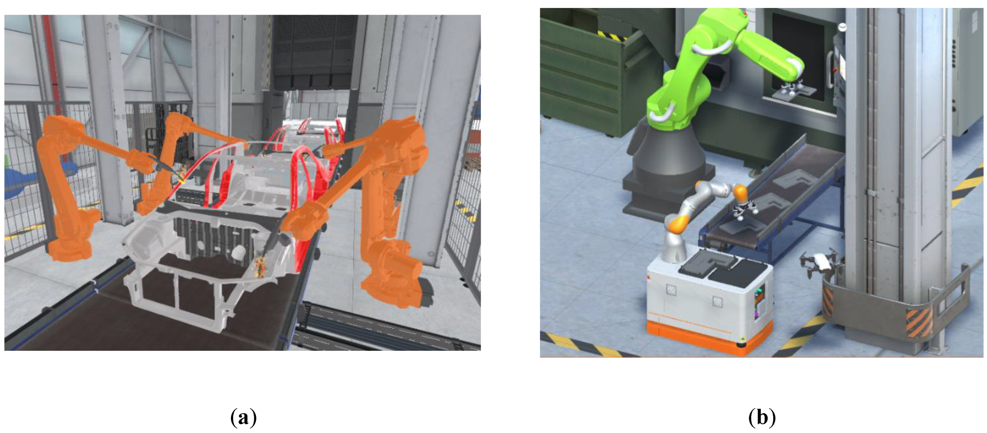
Figure 2.
Definition of object collider and safety sphere in the Unity scene.
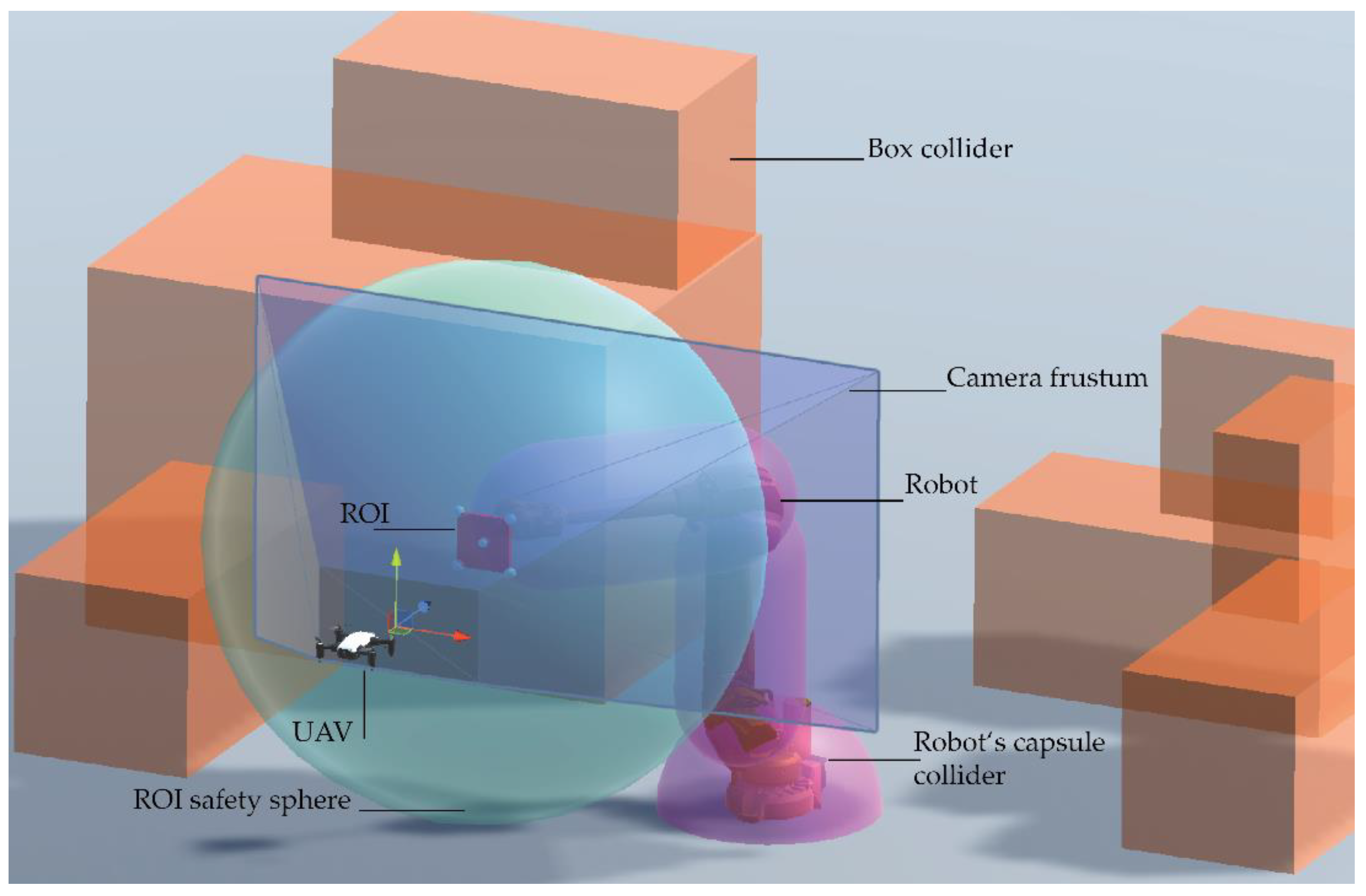
Figure 3.
Camera frustum of the UAV and the NCP, ROI and FCP in it. The corners c1–4 of the ROI are projected onto the NCP.
Figure 3.
Camera frustum of the UAV and the NCP, ROI and FCP in it. The corners c1–4 of the ROI are projected onto the NCP.
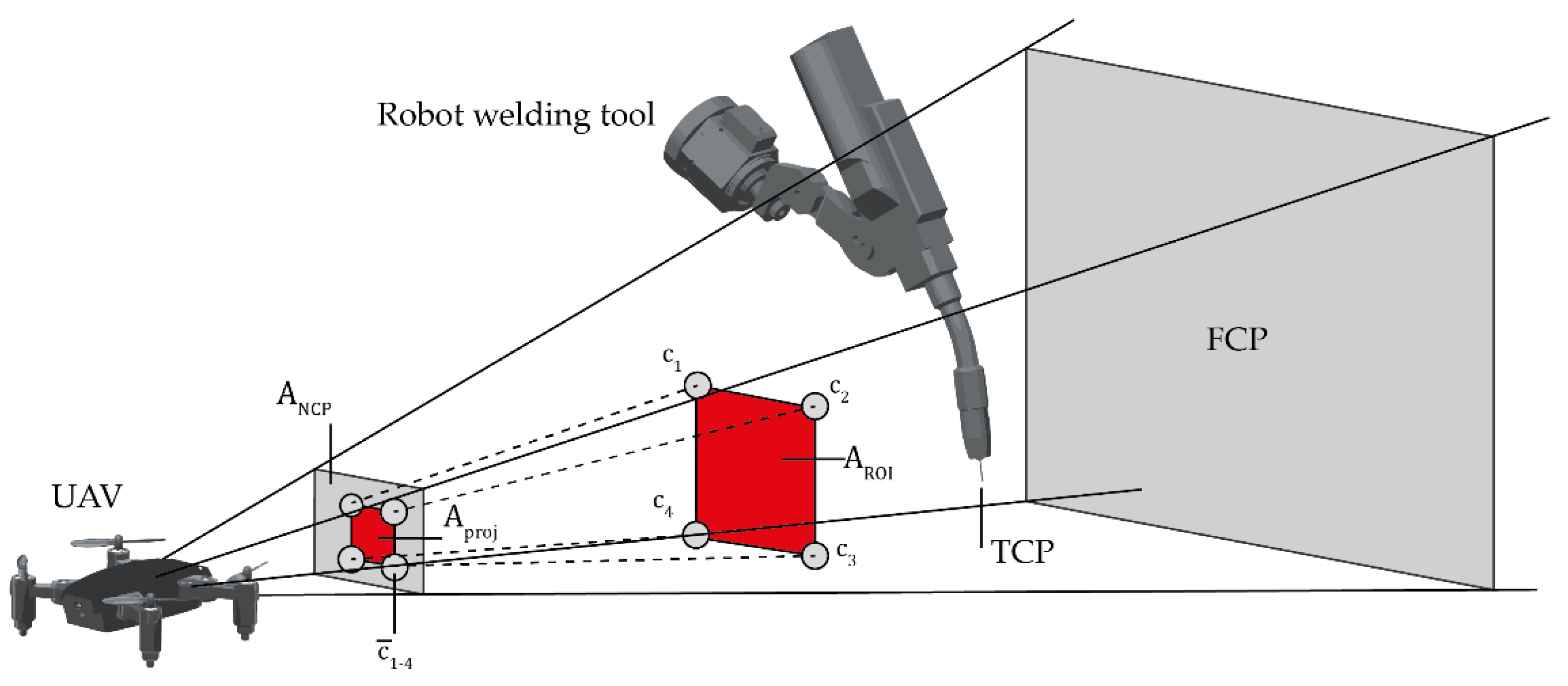
Figure 4.
Relationship between the angle , the target point , the , and the position of the ROI. If , the viewpoint is in sight, and vice versa, the ROI is fully visible from the viewpoint.
Figure 4.
Relationship between the angle , the target point , the , and the position of the ROI. If , the viewpoint is in sight, and vice versa, the ROI is fully visible from the viewpoint.
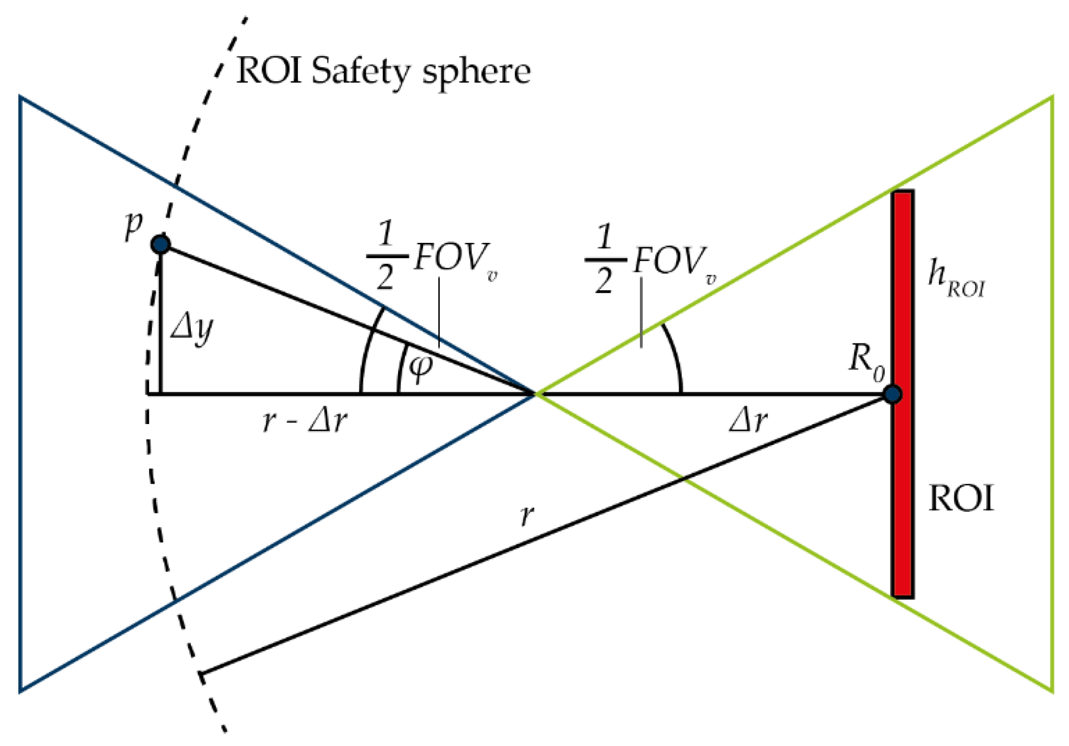
Figure 5.
Search procedure for finding the optimal viewpoint popt with the hill climber algorithm. Within the green frame are the termination criteria, which end the current cycle of the algorithm if true.
Figure 5.
Search procedure for finding the optimal viewpoint popt with the hill climber algorithm. Within the green frame are the termination criteria, which end the current cycle of the algorithm if true.
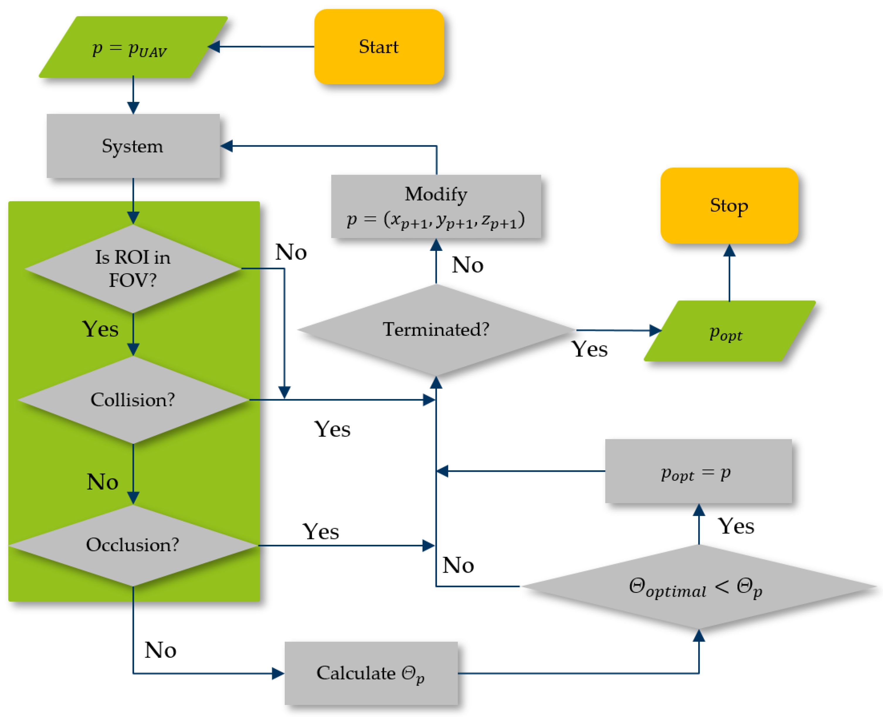
Figure 6.
Global minimum and maximum value for f(p). The ROI is visualized as a black plane. The blue spheres represent the global maximum, and the pink spheres are the global minimum for f(p). Shifting the sphere color from green to red indicates a rising value for f(p).
Figure 6.
Global minimum and maximum value for f(p). The ROI is visualized as a black plane. The blue spheres represent the global maximum, and the pink spheres are the global minimum for f(p). Shifting the sphere color from green to red indicates a rising value for f(p).
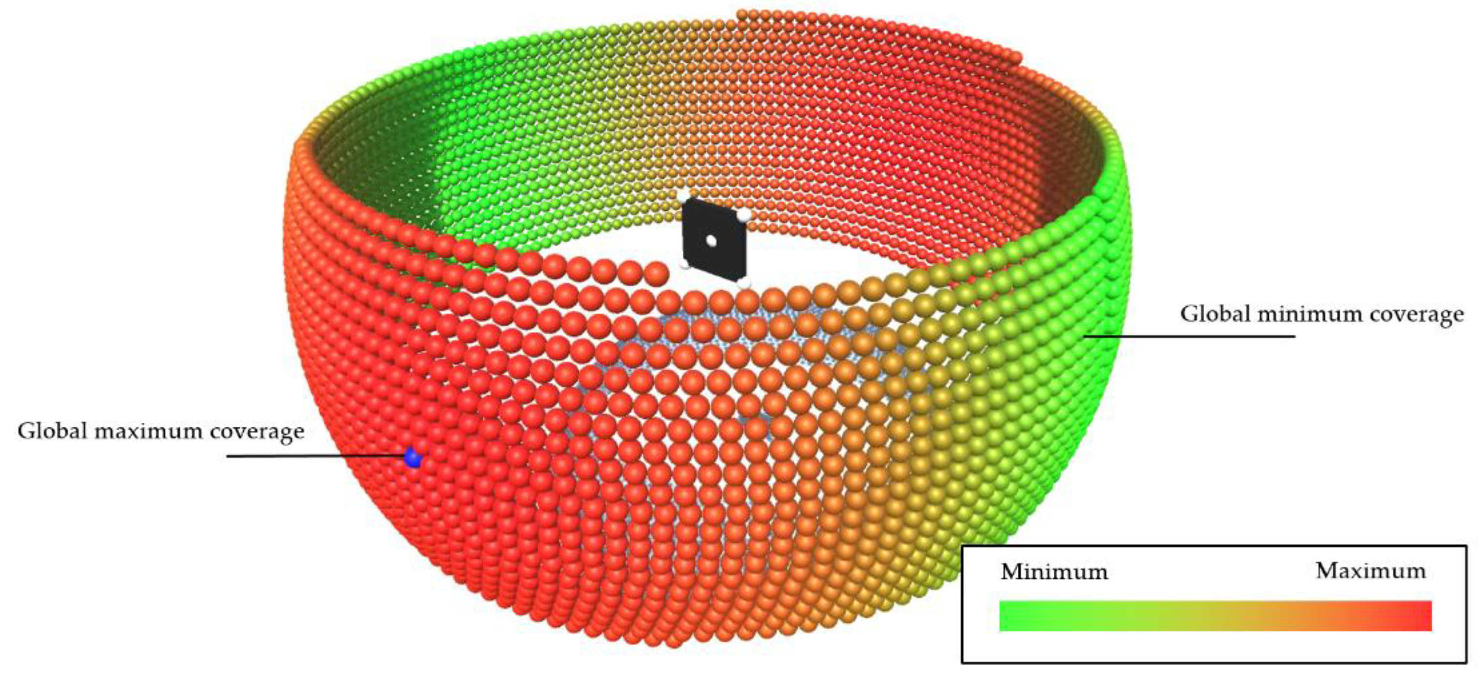
Figure 7.
Distortion of the projection of the ROI on the NCP when the viewpoint is moved in the vertical direction. The projected area Aproj thereby scales with the distortion which is a well-known effect in 3D projections.
Figure 7.
Distortion of the projection of the ROI on the NCP when the viewpoint is moved in the vertical direction. The projected area Aproj thereby scales with the distortion which is a well-known effect in 3D projections.
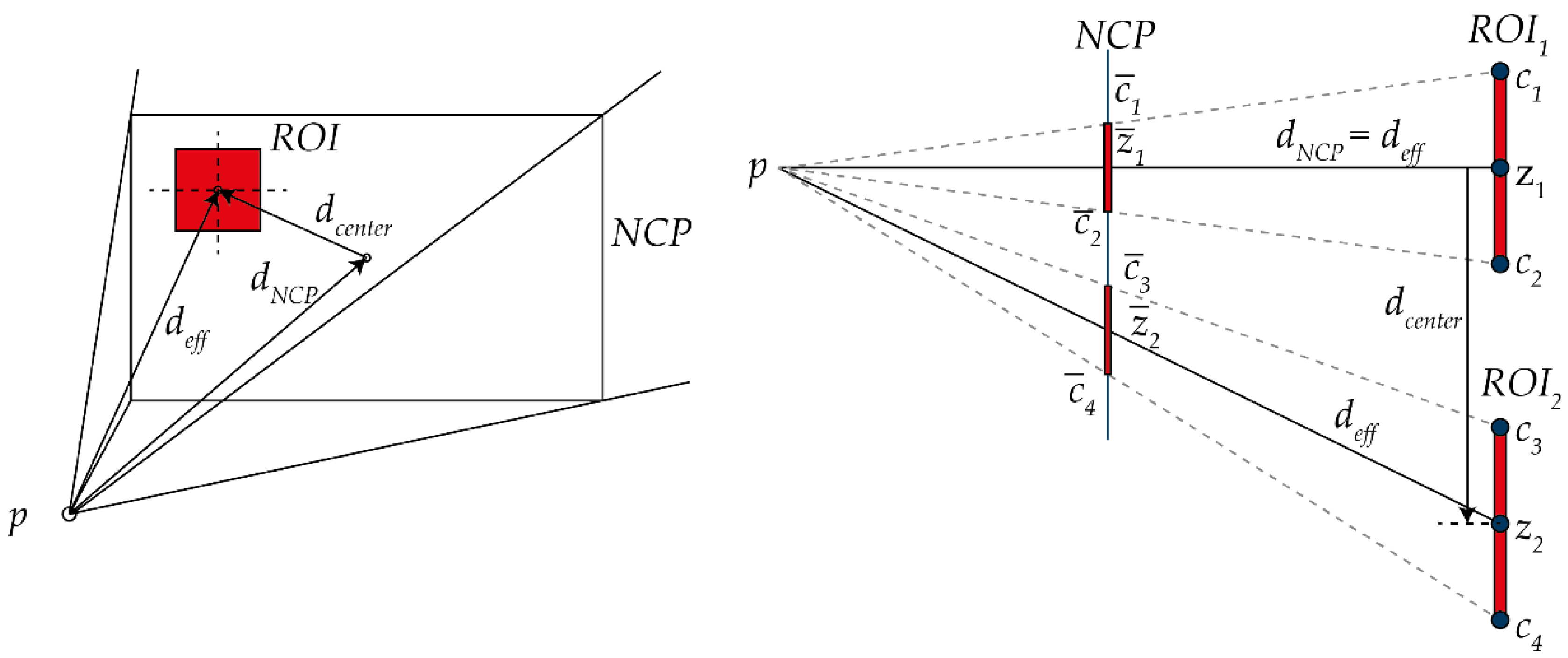
Figure 8.
Starting points for the search procedure, colorized in their later formation.
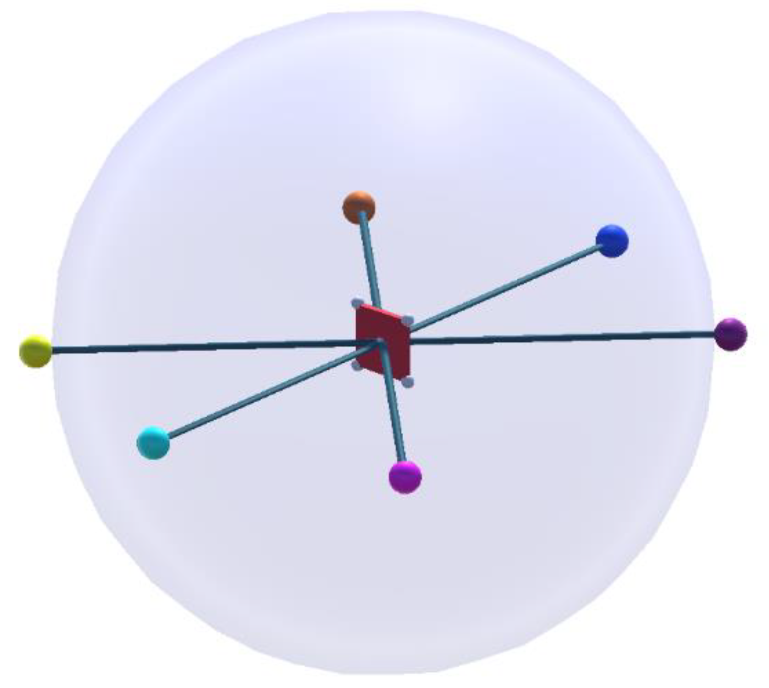
Figure 9.
The shortest path around the ROI safety sphere with waypoints, highlighted as single spheres. In (a), the shortest path is calculated on the XZ plane, which transforms the y-value of all points to zero. In (b), the waypoints are rotated back to the original rotation of Pstart and Pend.
Figure 9.
The shortest path around the ROI safety sphere with waypoints, highlighted as single spheres. In (a), the shortest path is calculated on the XZ plane, which transforms the y-value of all points to zero. In (b), the waypoints are rotated back to the original rotation of Pstart and Pend.
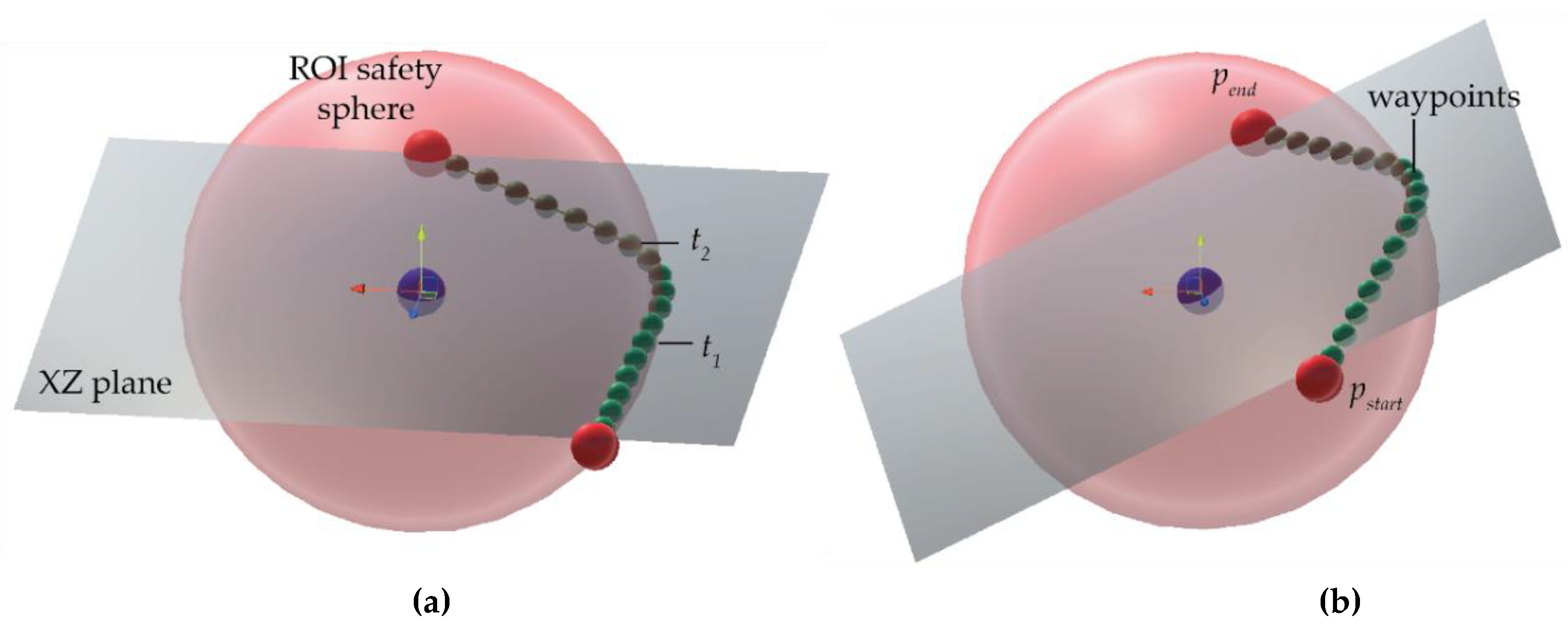
Figure 10.
Calculation of the tangential points t1 and t2 in the two-dimensional XZ-plane to calculate the circular path points and the tangential vectors. M is the center of the Thales circle, where R is the center of the safety sphere.
Figure 10.
Calculation of the tangential points t1 and t2 in the two-dimensional XZ-plane to calculate the circular path points and the tangential vectors. M is the center of the Thales circle, where R is the center of the safety sphere.
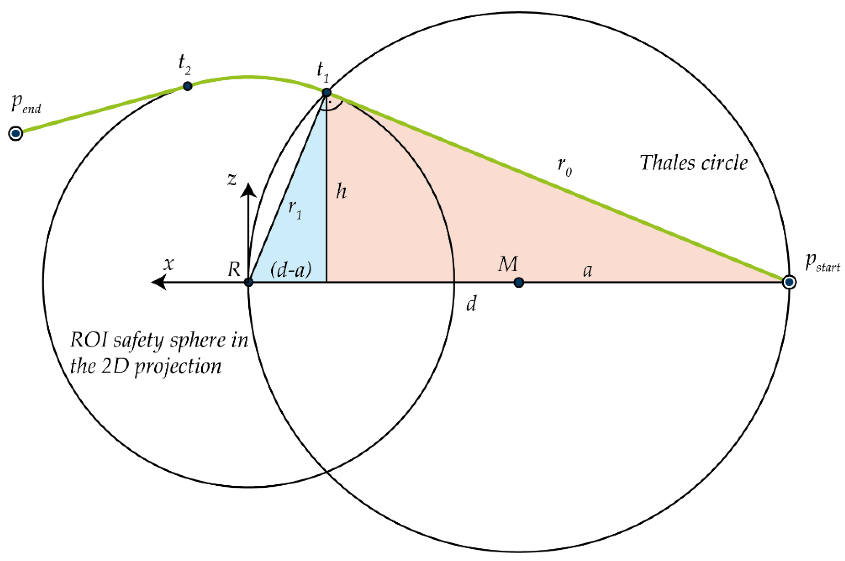
Figure 11.
The UAV maintains a safe position above the robot, ensuring a collision-free path to the viewpoints that represent the local maxima of perspective coverage along the optical axis of the ROI.
Figure 11.
The UAV maintains a safe position above the robot, ensuring a collision-free path to the viewpoints that represent the local maxima of perspective coverage along the optical axis of the ROI.
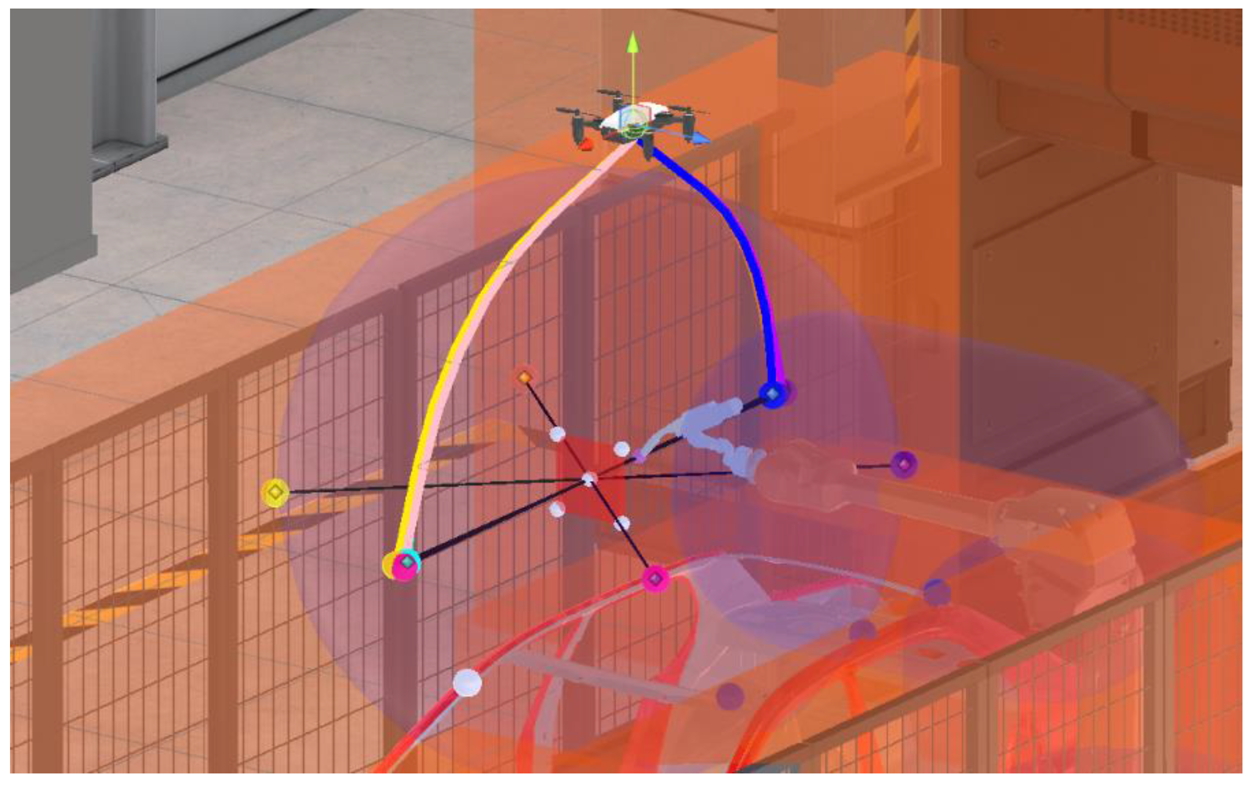
Figure 12.
Collider in the robot cell. (a) shows the side view, (b) is the top down view. The transparent orange box colliders stand for colliders in the scene. Purple capsule colliders surround robot’s joints and the sphere collider stands for the ROI’s safety sphere. The colliders do not block the view for the UAV.
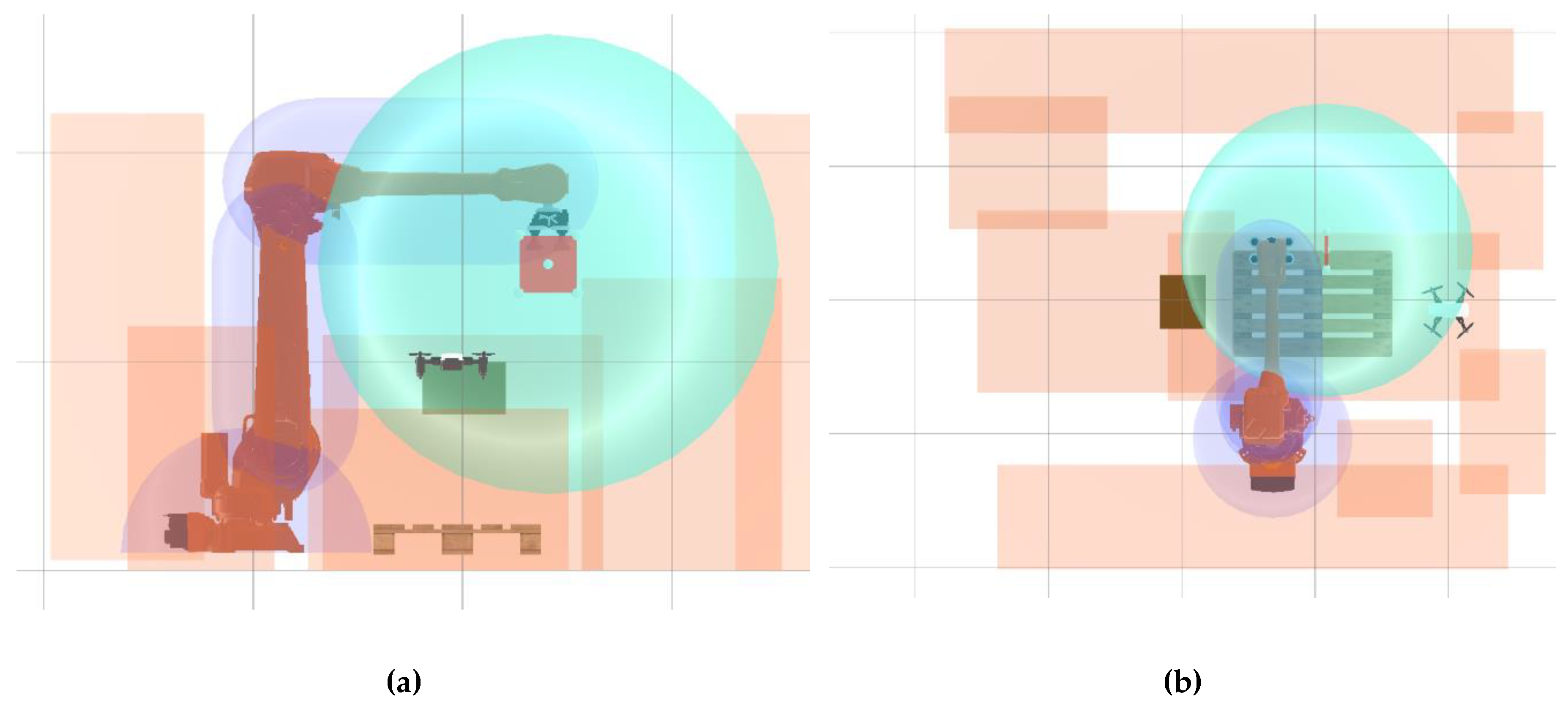
Figure 13.
In (a), screenshot of the UI for monitoring the scene and controlling the UAV. The paths to the available viewpoints are highlighted in their respective colors, as shown for the purple target here. The path of the TCP is highlighted in yellow; the UAV movement path is presented in white. (b) shows the perspective from the UAV’s camera.
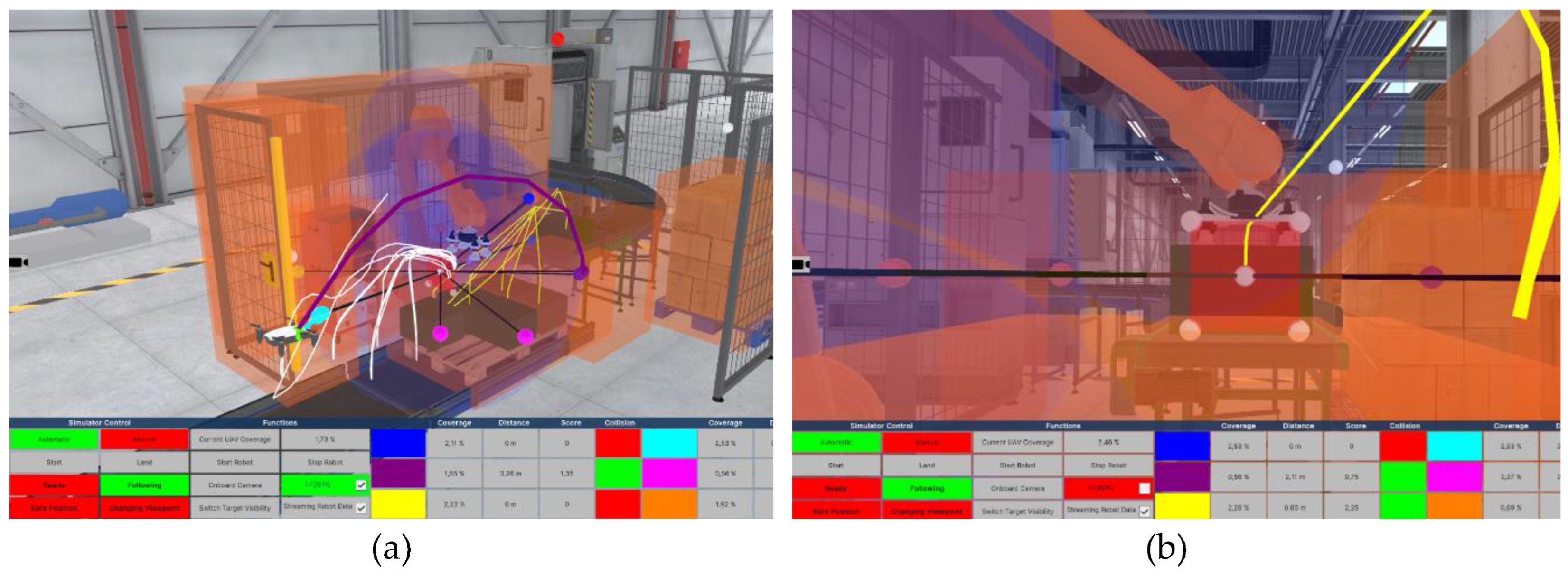
Figure 14.
Position of the four static cameras in the scene numbered from 1 to 4. In the bottom right corner, the view from camera 2 is presented.
Figure 14.
Position of the four static cameras in the scene numbered from 1 to 4. In the bottom right corner, the view from camera 2 is presented.
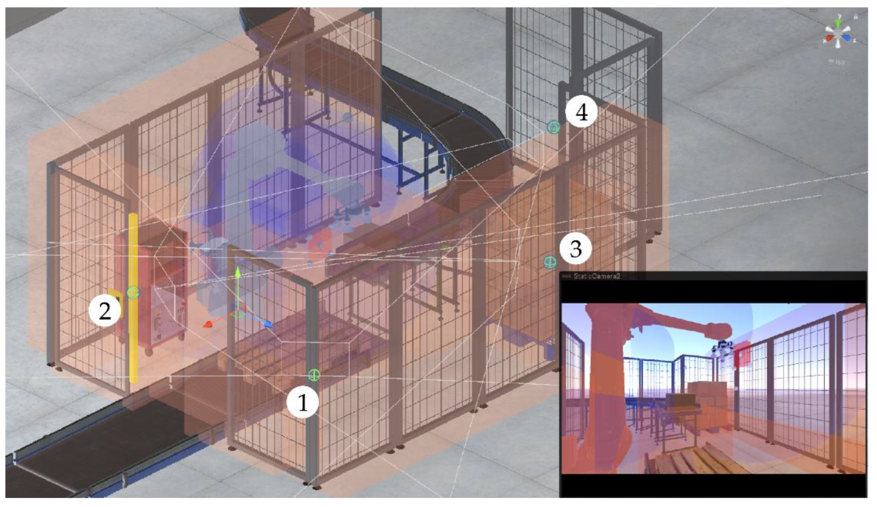
Figure 15.
Comparison of the perspective coverage of the UAV and the static cameras in the scene. The aggregated coverage is the highest perspective coverage of any viewpoint in the scene and, thereby, describes the highest coverage under the given constraints. The timeline below highlights the current viewpoint offering maximum perspective coverage over time.
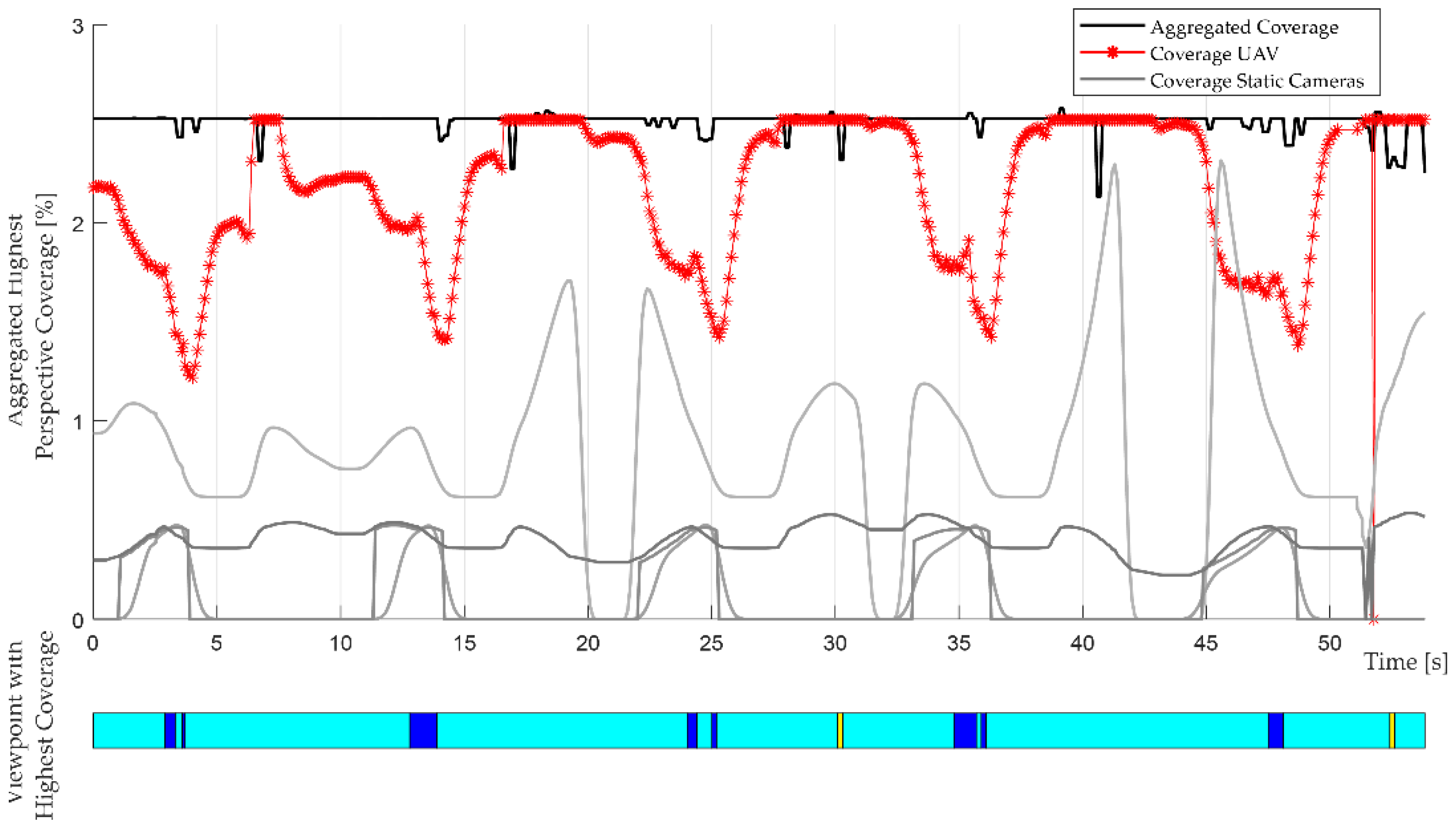
Figure 16.
The score of the current optimal viewpoint and the average score for the respective segments. Underneath is a line diagram displaying the color of the optimal viewpoint.
Figure 16.
The score of the current optimal viewpoint and the average score for the respective segments. Underneath is a line diagram displaying the color of the optimal viewpoint.
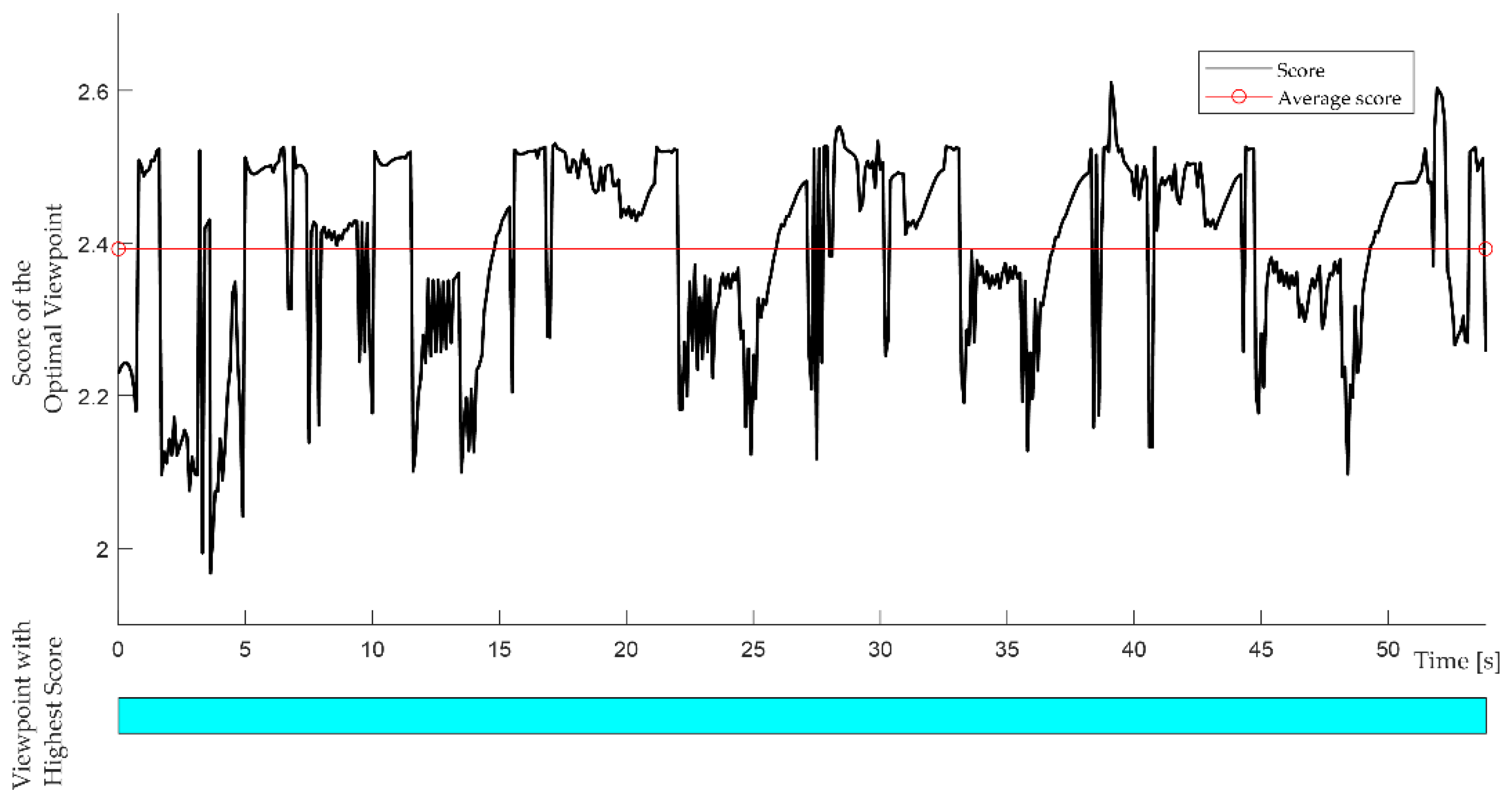
Figure 17.
Welding application simulated in Unity (a) and ABB RobotStudio (b). The simulation in (a) shows the UAV’s movement path as a white line. In (b), the robot’s movement path is highlighted in yellow and numbers visualize the sequence of contact points and the desired ROI’s rotation in the path segment.
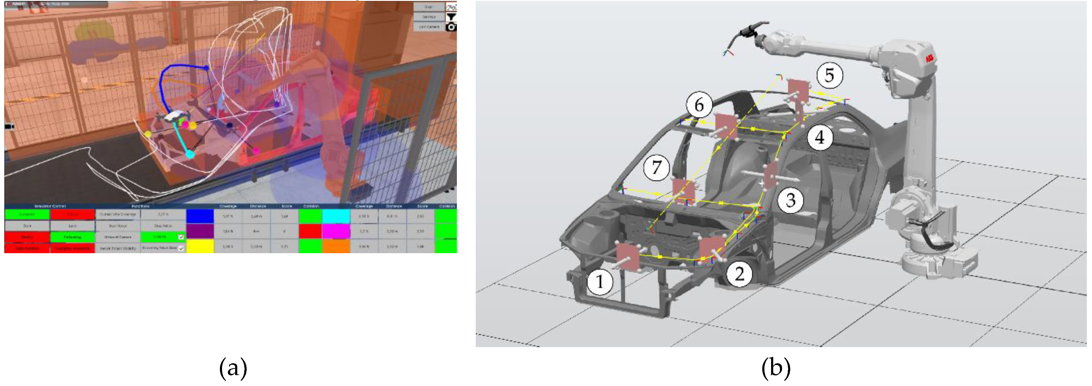
Figure 18.
Perspective coverage of the UAV and the static cameras in the welding application.
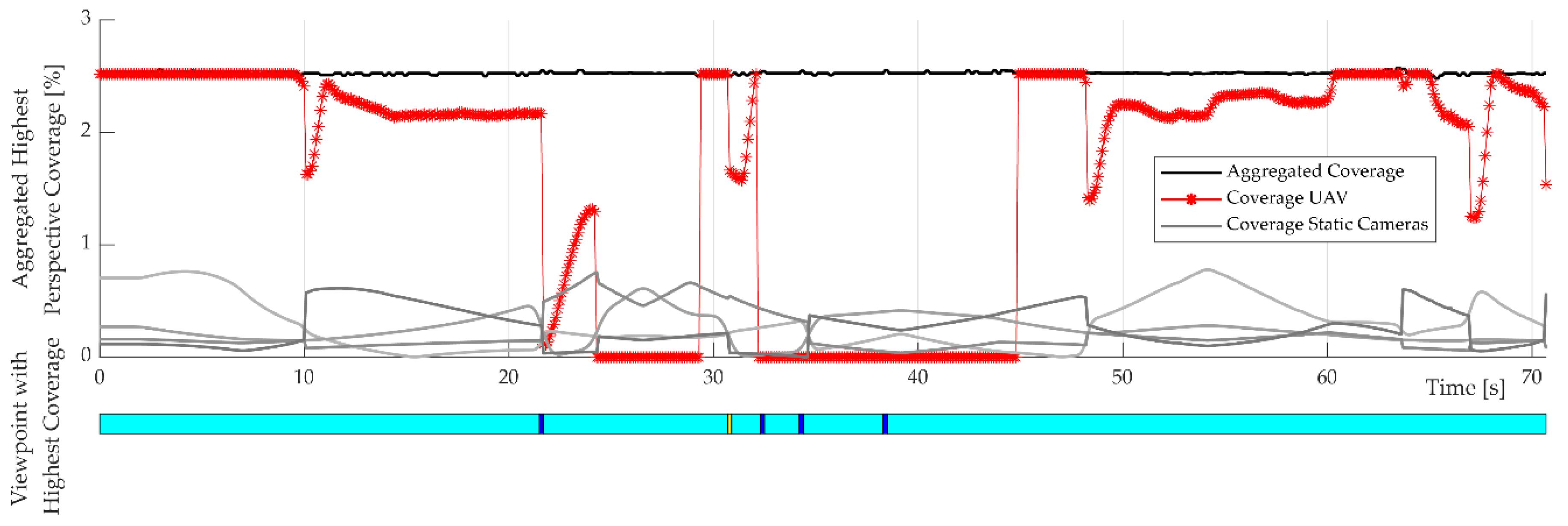
Figure 19.
Visualization of the score. Frequent changes of the optimal viewpoint can be seen in the bottom timeline. Black segments represent flights to the safe position, as there are no viewpoints available.
Figure 19.
Visualization of the score. Frequent changes of the optimal viewpoint can be seen in the bottom timeline. Black segments represent flights to the safe position, as there are no viewpoints available.
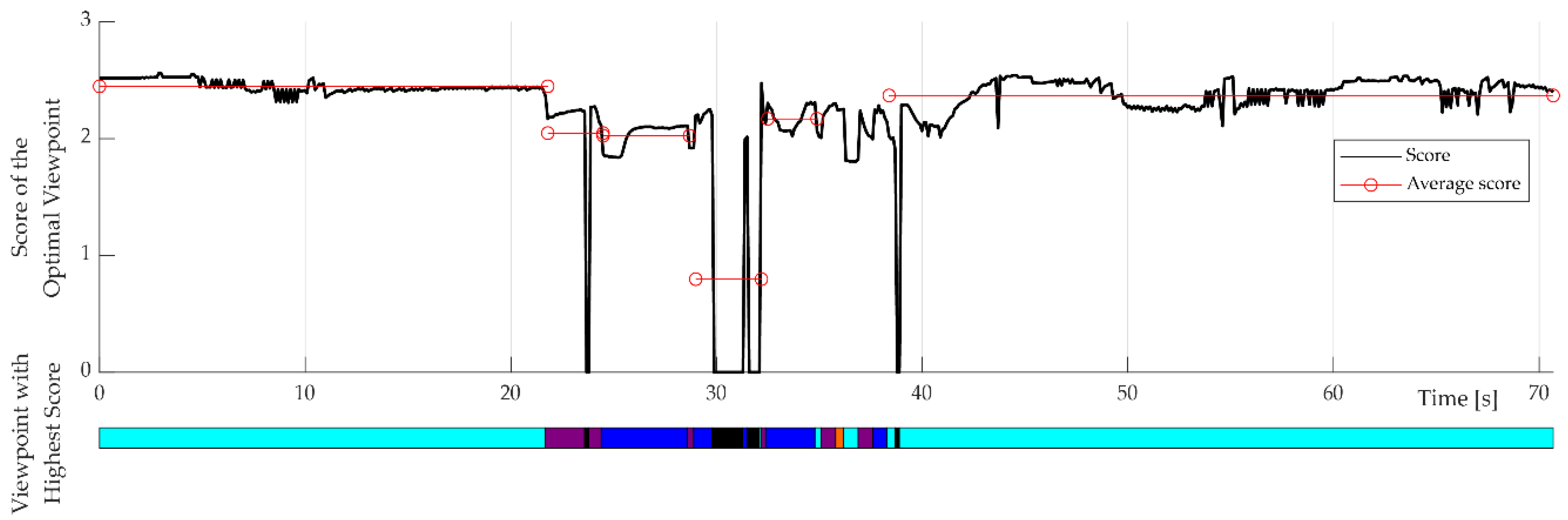
Figure 20.
Recorded score, perspective coverage and distance of the UAV from each viewpoint. The colors of the lines represent the color of the viewpoint. The current state of the UAV is shown below.
Figure 20.
Recorded score, perspective coverage and distance of the UAV from each viewpoint. The colors of the lines represent the color of the viewpoint. The current state of the UAV is shown below.
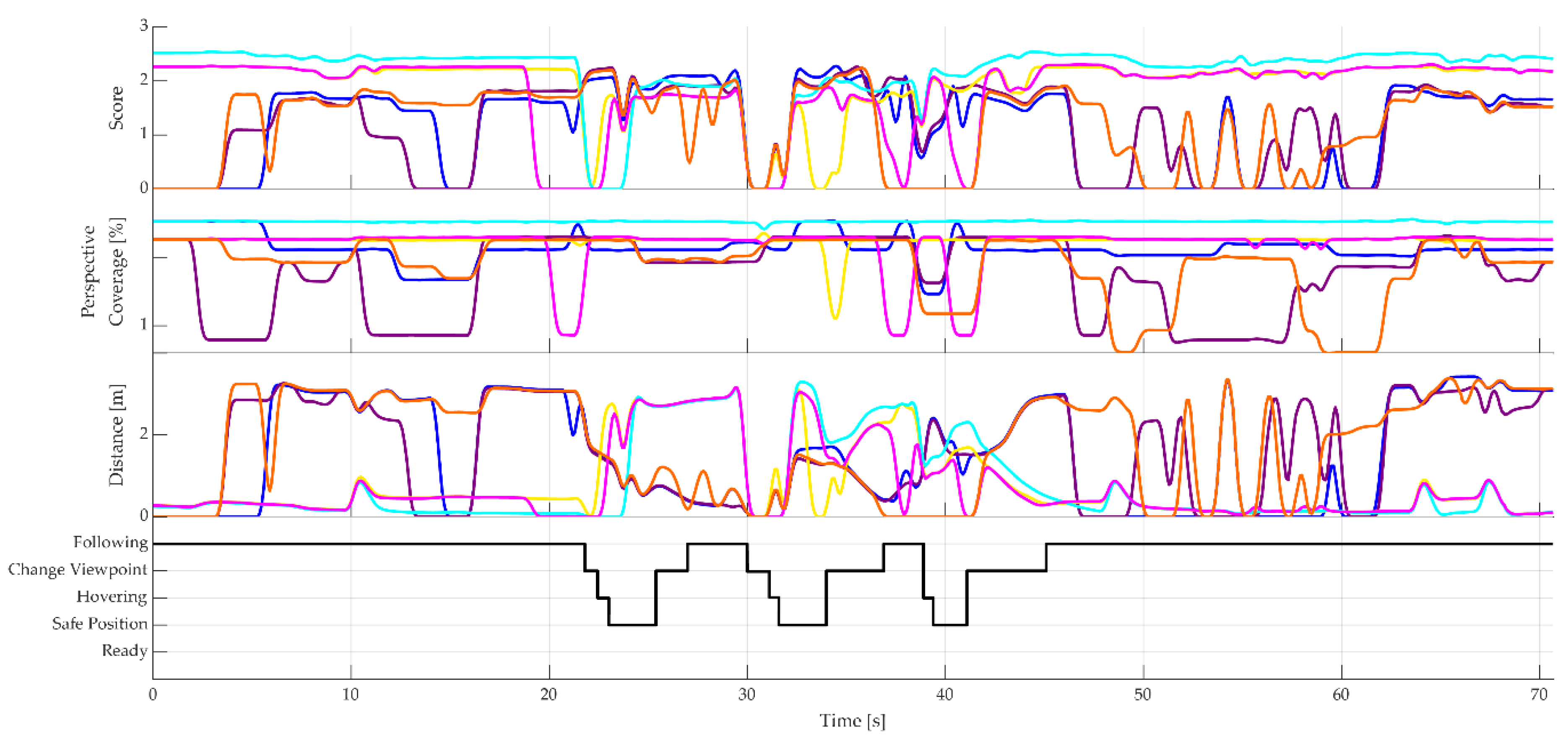

Table 1.
Requirements for using an UAV as a dynamic camera in any robotic application.
| Requirement | Explanation |
|---|---|
| Determine the optimal viewpoint from defined ROI | The user should be able to define the position, orientation and size of the ROI dynamically during a running task. The optimal viewpoint is defined from the geometric relationship of the ROI and the camera perspective to maximize process insight over the runtime. |
| Use UAV as dynamic camera within a control framework | An UAV is chosen as dynamic camera because it offers the highest flexibility in continuously achieving the optimal viewpoint, independent of the environment or other robot systems, which may be constrained by their reach and flexibility. A technical framework is needed to enable control while considering the specific characteristics of the system. |
| Unoccluded | The optimal viewpoint must grant a clear, unoccluded view onto the ROI. |
| Protected collision zones for path planning | Collision zones must be defined between the robot and the UAV, as well as between the UAV and its environment. Similarly, no-fly zones should be defined in the same way. These collision zones must also be considered when determining the available flight paths. |
| Comparison of the costs of viewpoints | The costs of getting from one viewpoint to another should be considered. The costs are defined as the length of the route and the lack of perspective coverage on the route. The path with the lowest costs is considered optimal. |
| Consideration of fluctuations in the selection of the optimal viewpoint | It can be assumed that there are system states in which the costs of flying a path are similar, but sudden changes in path decisions can occur. This would result in an unstable flight behavior of the UAV, as it responds to spontaneous changes in movement direction. Therefore, a decision-making method or strategy should be implemented to ensure consistent decision behavior. |
| Measurability of method | The entire method of visually covering a ROI should be measurable. For this purpose, perspective coverage of the ROI over time should be expressed in a numerical value and the resulting method should be assessable. |
Table 2.
The implemented states and their specific actions.
| State | Explanation |
|---|---|
| Following State | In the following state, the UAV follows an optimal viewpoint until it is not available anymore or the threshold condition for is reached. If the optimal viewpoint changes, the UAV switches to the changing viewpoint state. Arrived at the next viewpoint, the UAV returns to the following state. |
| Changing Viewpoint State | This state becomes active when a next viewpoint has been identified either if is better or if the last followed is not available anymore. The UAV navigates to the next viewpoint and then returns to the following state. |
| Hovering State | If a viewpoint is suddenly no longer available in the following state, the UAV switches to the hovering state. In this state, it remains hovering in the air for a maximum of two seconds and waits for a viewpoint to become available. If no viewpoint becomes available within this time, the UAV switches to the safe position state. |
| Safe Position State | The safe position is a manually defined point by the user and is located to be reached safely, e.g. above the robot with a sufficient safety distance. Flying to the safe position has to be completed before changing to another viewpoint, in order to avoid abrupt changes in direction. The UAV waits at the safe position until a new viewpoint becomes available. |
Table 3.
Results of the palletizing task.
| Final Results | Value |
|---|---|
| Theoretically maximum coverage in the scenario | 2.513 % |
| Average perspective coverage of the UAV | 2.166 % |
| Highest average coverage of a static camera | 0.850 % |
| Portion of following time | 100 % |
| Portion of changing time | 0 % |
| Portion of safe position state time | 0 % |
| Portion of time hovering | 0 % |
| Number of viewpoint changes | 0 |
| Number of safe position flights | 0 |
Table 4.
Results for the welding application.
| Results | Value |
|---|---|
| Theoretically highest possible coverage in the scene | 2.513 % |
| Average perspective coverage of the UAV | 1.667 % |
| Highest average coverage of a static camera | 0.298 % |
| Portion of following time | 74.136 % |
| Portion of changing time | 14.987 % |
| Portion of safe position state time | 8.199 % |
| Portion of time hovering | 2.678 % |
| Number of viewpoint changes | 5 |
| Number of safe position flights | 3 |
Disclaimer/Publisher’s Note: The statements, opinions and data contained in all publications are solely those of the individual author(s) and contributor(s) and not of MDPI and/or the editor(s). MDPI and/or the editor(s) disclaim responsibility for any injury to people or property resulting from any ideas, methods, instructions or products referred to in the content. |
© 2025 by the authors. Licensee MDPI, Basel, Switzerland. This article is an open access article distributed under the terms and conditions of the Creative Commons Attribution (CC BY) license (http://creativecommons.org/licenses/by/4.0/).
Copyright: This open access article is published under a Creative Commons CC BY 4.0 license, which permit the free download, distribution, and reuse, provided that the author and preprint are cited in any reuse.


