1. Introduction
The number of pistons in an axial-piston pump significantly affects the vibrations of the pump housing. More pistons can lead to a more balanced distribution of forces through the pump. This balance helps reduce vibration, as the alternating forces from each piston can cancel out to some degree [
1,
2,
3]. The overall design and configuration of the pump, including the number of pistons used, also play a role.
For example, pumps designed with an even number of pistons may exhibit different vibration patterns than hose with an odd number [
4,
5].
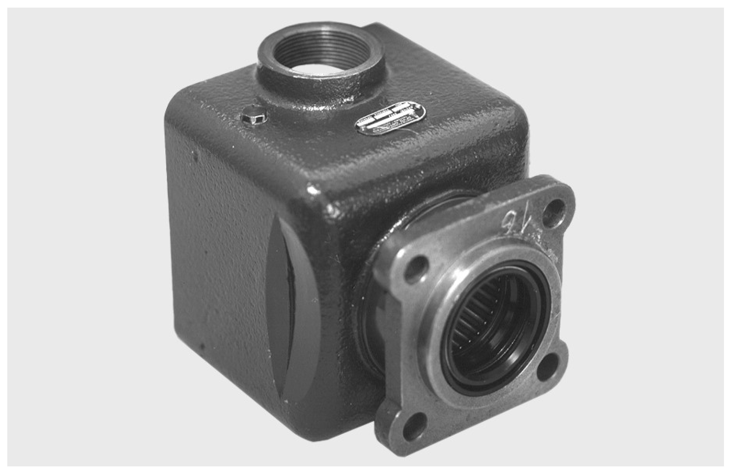
Figure 1.
The pump housing.
Figure 1.
The pump housing.
The mathematical model relates pressure pulsations to vibration frequencies through coupled differential equations [
6]. Analysis of the system’s response to pressure changes reveals how increased pulsation leads to higher vibration frequencies, especially under resonant conditions [
7]. Using numerical methods or simulations can provide further insight into pump dynamics under different operating conditions.
A higher number of pistons can result in reduced torque fluctuations in the drive mechanism, which contributes to smoother operation and less vibration [
8,
9]. Fewer pistons can create larger torque spikes, increasing the potential for vibration [
10].
The arrangement and number of pistons can affect how the pump absorbs and dissipates energy. More pistons could improve the damping characteristics of the system, reducing the amplitude of vibrations transmitted to the case [
11,
12,
13].
2. Mathematical Model
Mathematical modeling, fluid dynamic behavior, flow characteristics and pressure variations inside the pump are described by differential equations by introducing systematic assumptions and definitions with certain limitations. Fluid properties, structural parameters and forces are described by appropriate equations [
14].
Mathematical modeling of axial piston pumps is a multi-faceted process that involves careful consideration of equations, components, operating conditions, and physical constraints. This approach not only improves understanding of pump dynamics, but also aids in the design and optimization of hydraulic systems for improved performance and reliability [
15].
2.1. Description of Mathematical Models of Pump Processes
The models are combined into a set of differential equations that describe the time-varying behavior of the pump under different operating conditions. Solving these equations requires numerical methods (e.g., Runge-Kutta) to simulate the dynamic response of the pump in different scenarios [
16,
17].
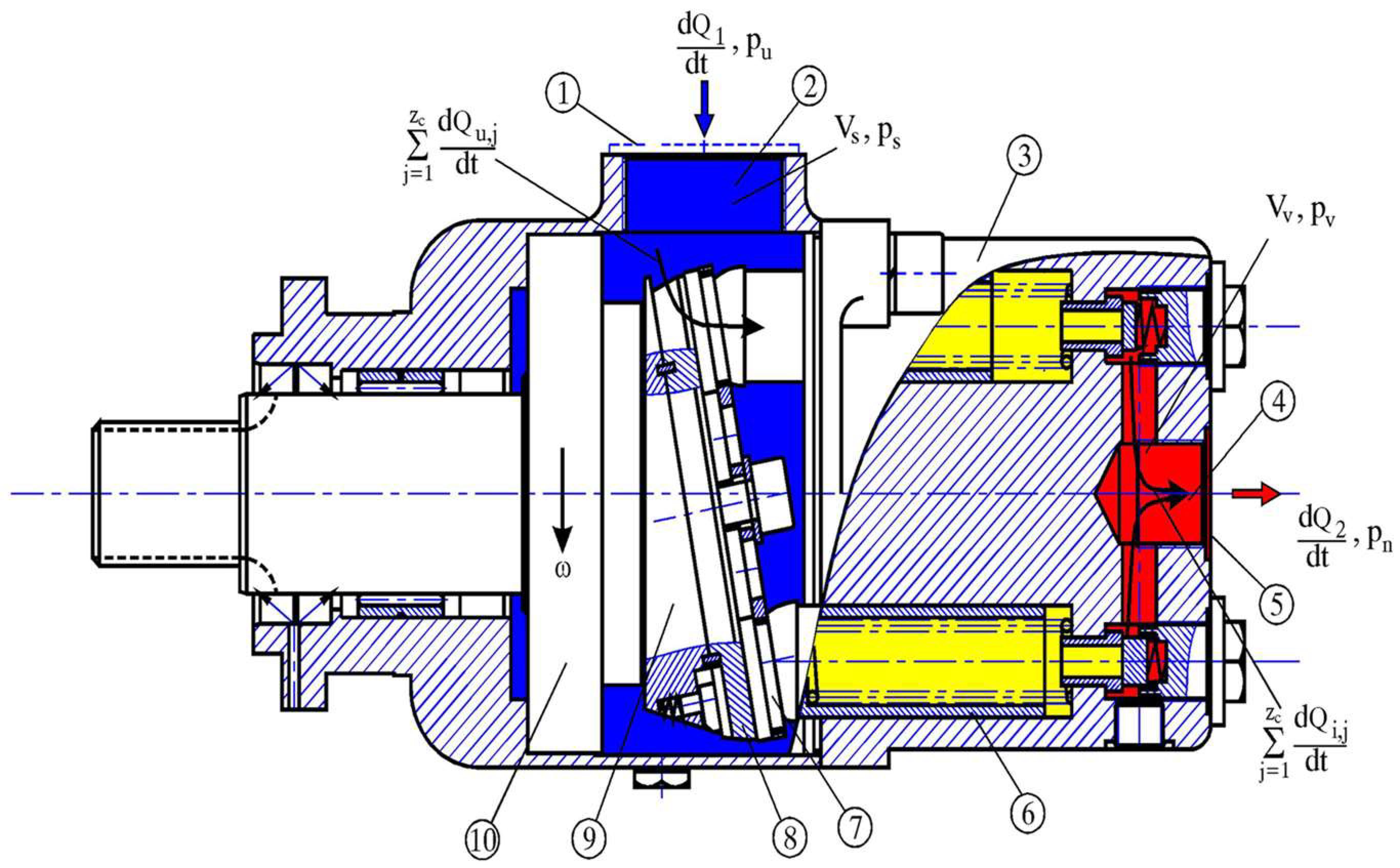
Fluid flow into the suction chamber of the pump at location 1,
Figure 2:
where:
σ1=1 for pu≥ ps , σ1=-1 for pu< ps
- geometrical flow section of the intake pipe
- flow coefficient of the intake pipe
Figure 2.
Description of the schematic representation of fluid flow in an axial piston pump: 1. Suction pipe connection, 2. Pump suction space,3. Cylinder block, 4. Pump delivery,5. Supply pipe connection, 6. Piston, 7. Lifting plate, 8. Inclined plate.9. Drive pump shaft, 10. Drive pump shaft support.
Mass flow of fluid when filling one pump cylinder:
where:
σu=1 for ps≥ pc , σu = -1 for ps<pc
Au- geometric flow cross-section
- geometric flow cross-section coefficient
The mass balance of the suction chamber is:
where:
j=1,2,...,zc, zc - cylinder numbers
Pressure equation in the suction chamber of the pump:
- modulus of elasticity;
- the driving shaft angle,
Pressure in the pump cylinder:
where:
Vcx - the volume of the pump cylinder achieved by moving the piston
, - current displacement of the piston.
Cylinder volume by moving the piston:
where:
j=1,2,..., zc - the numbers of piston
Fluid flow from the pressure chamber of the pump:
where:
σ2=1 for pv≥pn , σ2 = -1 for pv< pn
A2- geometrical flow section of the delivery pipe line
Pressure in the pressure chamber of the pump:
Fluid leakage through the concentric gap between the cylinder and the piston:
where:
- Cylinder diameter,
- Radial clearance between the piston and the cylinder,
η- Dynamic viscosity,
- current displacement of the piston,
pc Cylinder pressure,
ps - Suction pressure,
- Fluid density in the cylinder.
2.2. Mathematical Model of Balance of Forces
Fh the hydraulic force,
p is the pressure of the fluid, and
A is the cross-sectional area of the piston.
Mechanical forces:
Fm spring forces (like a force from a spring),
Ff friction forces between the piston and the cylinder wall.
The friction force (Ff) between the piston and the cylinder wall is a resistive force that opposes the relative motion between these two components.
Force balance, to analyze the motion of a piston, we must consider all the forces acting on it.
3. Experiment
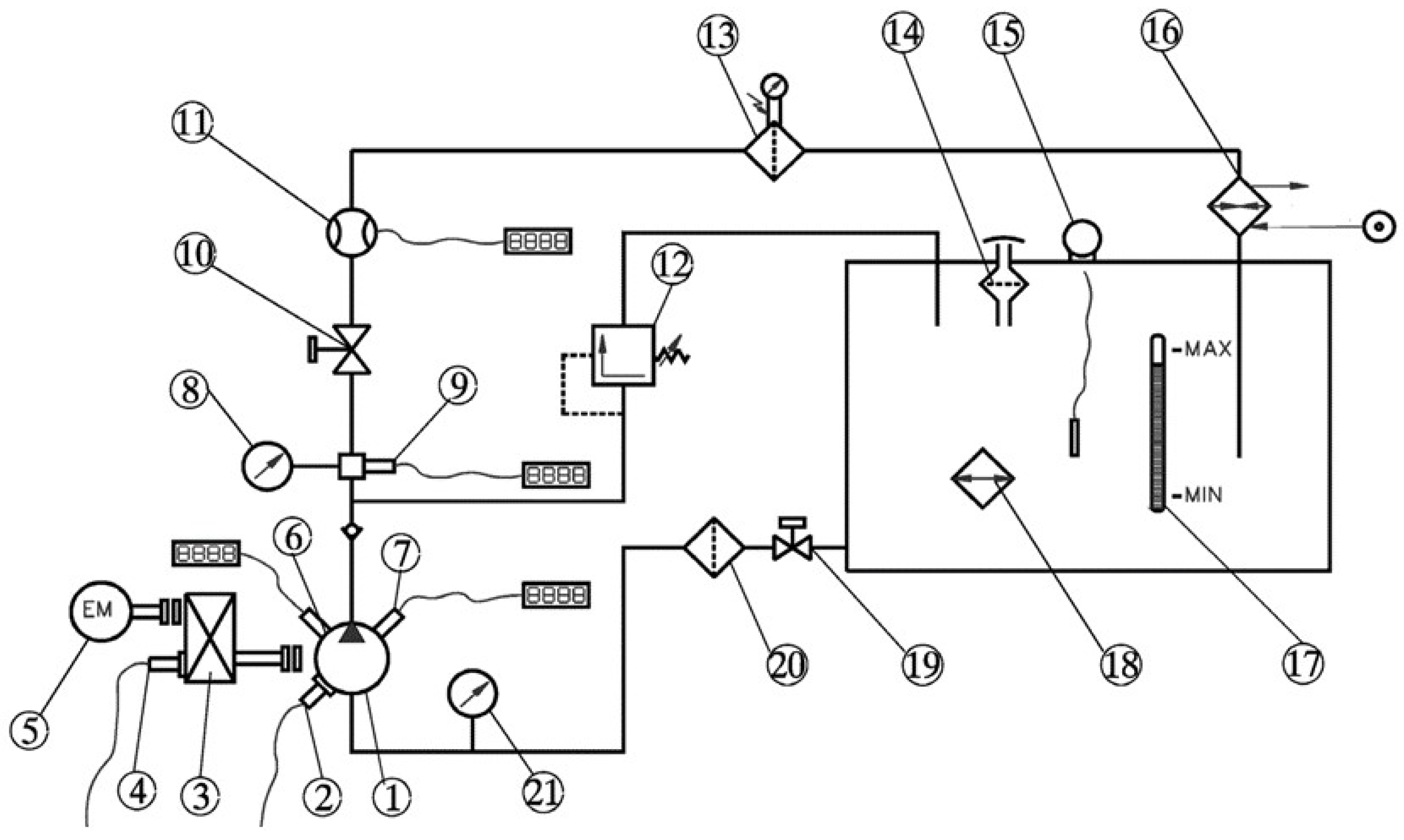
Figure 4 shows the hydraulic installation for testing the piston-axial pump, which consists of: 1.Tested pump; 2. Vibration measuring transducer; 3. Reducer; 4. Incremental rotary encoder; 5. Electric motor; 6. Cylinder pressure transducer; 7. Pressure transducer in pressure chamber; 8. Manometer; 9. Absolute pressure transducer; 10. Faucet; 11. Measuring turbine for flow; 12. Valve for pressure limitation; 13. Return filter; 14. Pourer with vent; 15. Thermometer in the tank; 16. Refrigerator; 17. Working fluid level indicator; 18. Heater; 19. Suction tap; 20. Suction filter; 21. Manovacumeter.
Table 1.
Technical data of the tested pump.
Table 1.
Technical data of the tested pump.
| Number of pistons |
z = 8 |
| Nominal pressure |
pN = 200.0 bar |
| Suction pressure |
ps = 4.45 bar |
| Volume of the pressure space |
VS = 2.71•10- 4 m3
|
| Radial clearance of the piston in the cylinder |
rPC = 9.78•10- 6 m |
| Volume of the harmful space |
VHS = 30.25•10-6 m3
|
| Angle of the beginning of the suction phase |
A SP = 31.030 O
|
| Stiffness of the pressure valve spring |
S VS = 1108.0 N/m |
| Mass of the pressure valve plate |
mVP = 4.3310 - 3 kg |
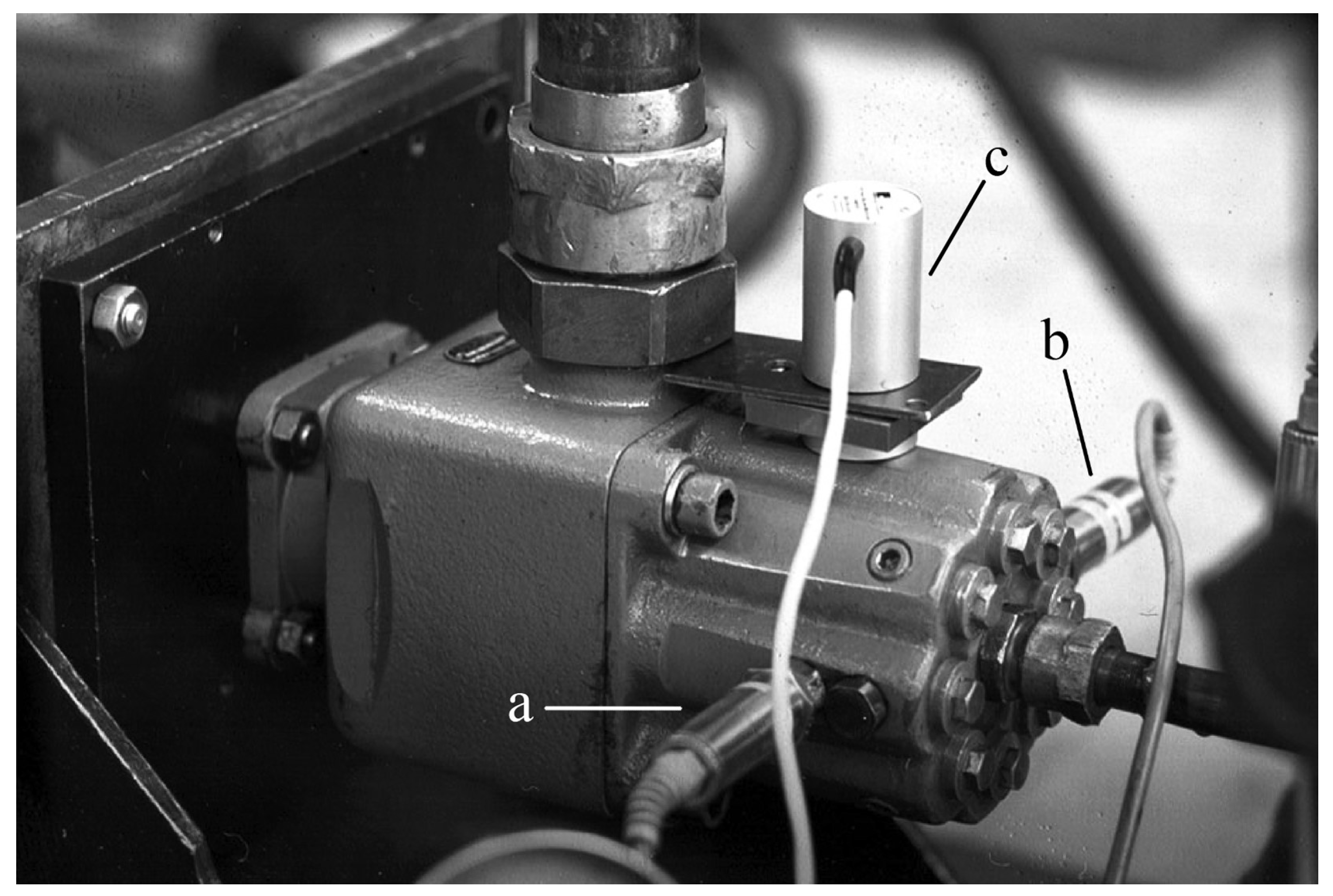
Pressure transducers, based on measuring tapes type P3MA, range 500 bar, accuracy class 0.1 and bandwidth 100 kHz (
Figure 5a,b) were used to measure the pressure in the cylinder and pressure chamber of the pump. The flow measurement was performed with a measuring turbine type RE2 25/180 l/min, accuracy class 0.4.
An incremental encoder type ROD 426 E, with 1024 optical markers and a maximum number of revolutions of 12000 min-1, was used to measure the rotation angle of the pump’s drive shaft. Using an accelerometer with a measurement range of 5 m/s2, the vibration amplitudes of the housing were measured.
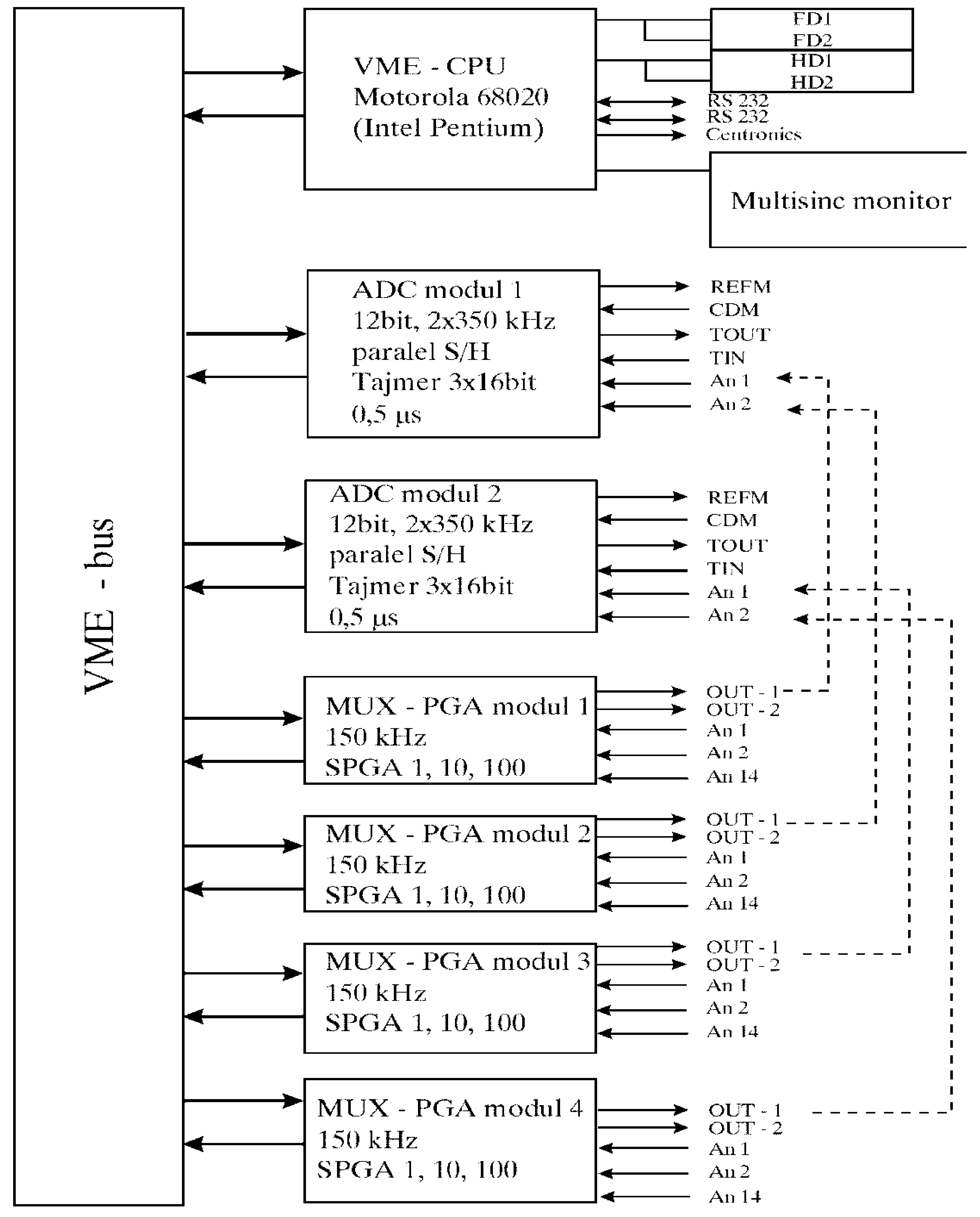
The ultra-fast measurement and control system ADS 2000 - CADEX (
Figure 6 and
Figure 7) enables continuous measurement and calculation of the characteristic parameters of the pump’s working cycle in real time.
The processor takes data from the A/D converter in real time directly into the CPU-DRAM. At the same time, the processor controls the amplifier and multiplexer cards in real time. Software for measuring cyclic and non-cyclic rapidly changing processes with graphic online display was developed for the system. Statistical processing of the measured data in the measurement process is performed with a graphic display. The maximum measurement speed is 3MHz with 6... 12 simultaneous A/D converters at 50,000,000 measured data in one ensemble. Up to 4 VME-CPU cards with Motorola 68020... 68060, Intel Pentium, Digital Alpha or Motorola Power PC processors can be integrated into the system.
The VME-bus ADC system uses ADC cards, each containing two 12-bit A/D converters, each with a sampling rate of 350 kHz, operating simultaneously. Data acquisition can be triggered by either an angle encoder pulse or a timer. The hardware registers the incremental angle encoder reference mark for synchronization. However, the system does not perform real-time error checking or angular encoder status monitoring. The system is scalable and can integrate up to six A/D cards, providing a total of 12 A/D converters.
The VME-bus PGA multiplexer and amplifier module has six high-speed instrumentation amplifiers for direct connection of full-bridge tape measure transmitters with 5 V DC supply (options 12 or 15). The maximum switching speed is 150 kHz. 4 VME-bus PGA modules are integrated into the implemented system.
The applied measurement system enables simultaneous measurement on 4 fast analog channels, with parallel measurement of time intervals from the angle mark to the incremental angle encoder mark “changed to”. The measurement system enables simultaneous data acquisition from four fast analog channels, synchronized with precise measurements of the time interval between the encoder pulse and the reference mark (index pulse or Z-pulse) from the same encoder.
4. Comparison of Simulation and Experimental Results
Measurements of cylinder pressure, pump pressure chamber pressure, pressure pipeline pressure, and pump housing vibration amplitude were acquired as a function of the drive shaft angle. Data were sampled at intervals of approximately 0.09° of shaft rotation, resulting in 4096 samples per revolution. An optical incremental rotary encoder with 1024 pulses per revolution (PPR) was used. An interface with a multiplication factor of four (quadrupling) was employed to generate 4096 pulses per revolution [
19,
20].
To perform Fast Fourier Transforms (FFTs) on the measured signals, each signal was sampled at 4096 points per revolution (cycle). With five measured signals (four pressures and one vibration), this resulted in a total of (4 + 1) × 4096 = 20,480 data points per revolution and 204,800 data points for 10 consecutive revolutions. Measurements were conducted across seven operating modes, with parameters detailed in
Table 2.
To assess the uniformity of the drive shaft’s angular speed and monitor the performance of the incremental rotary encoder, four analog signals (pressures and vibration) were simultaneously digitized using four high-speed analog-to-digital converters (ADCs). Concurrently, the time interval between consecutive encoder pulses was measured. Data were acquired for ten consecutive shaft revolutions under each operating mode to evaluate the repeatability of the measurements.
4.1. Pressure Dynamics
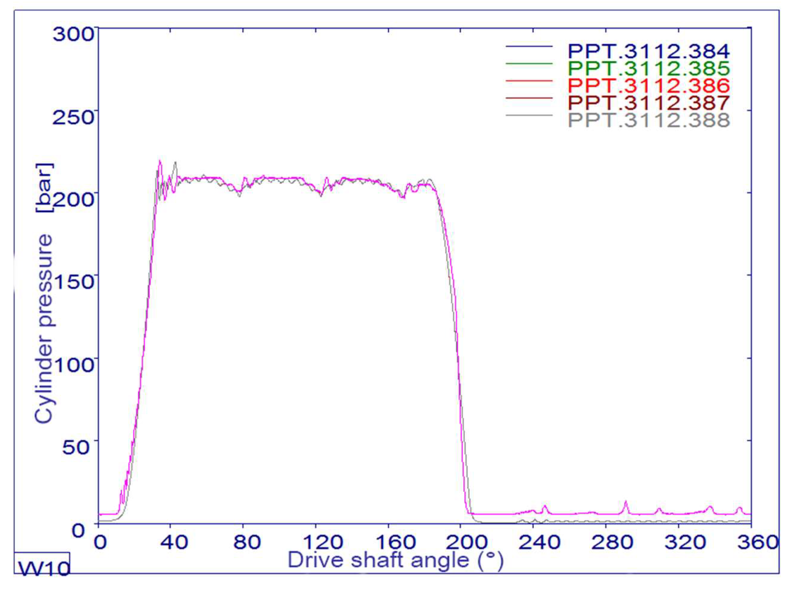
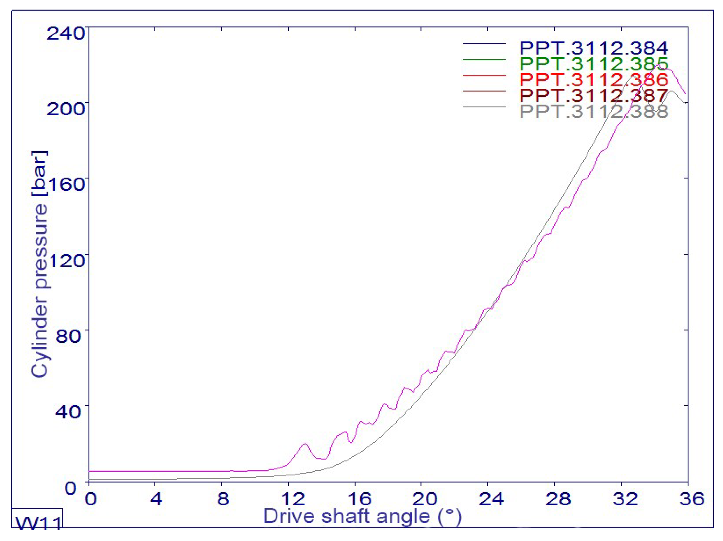
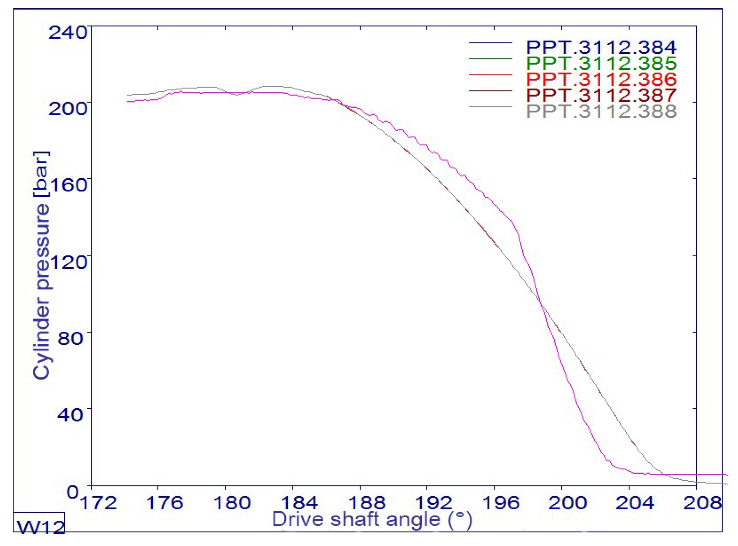
Figure 8 shows the pressure profile over one drive shaft revolution (following 388 operating cycles) of the eight-piston axial piston pump. The pressure profile exhibits a characteristic rise, a period of near-constant pressure, and a subsequent decline. This is followed by the suction phase, marking the start of the next pumping cycle.
The diagram shows colored lines that represent the results of the experimental test (red), and the other colors represent the results of the simulation of the mathematical model for different combinations of the pump’s operating and structural parameters. The diagram shows the different peaks corresponding to the maximum pressure during discharge and the valleys where the pressure drops during suction. Observing the sharpness or gradual nature of these peaks can provide insight into pump performance characteristics and fluid handling efficiency.
Given the transducer’s 100 kHz bandwidth, it is capable of capturing fast dynamic pressure. Thi allows for a more detailed understanding of pressure transients that may occur during rapid changes in pump operation. An accuracy class of 0.1 indicates high reliability in the pressure reading. It was important to ensure that the transducer was properly calibrated to maintain this accuracy, especially given the high-pressure range.
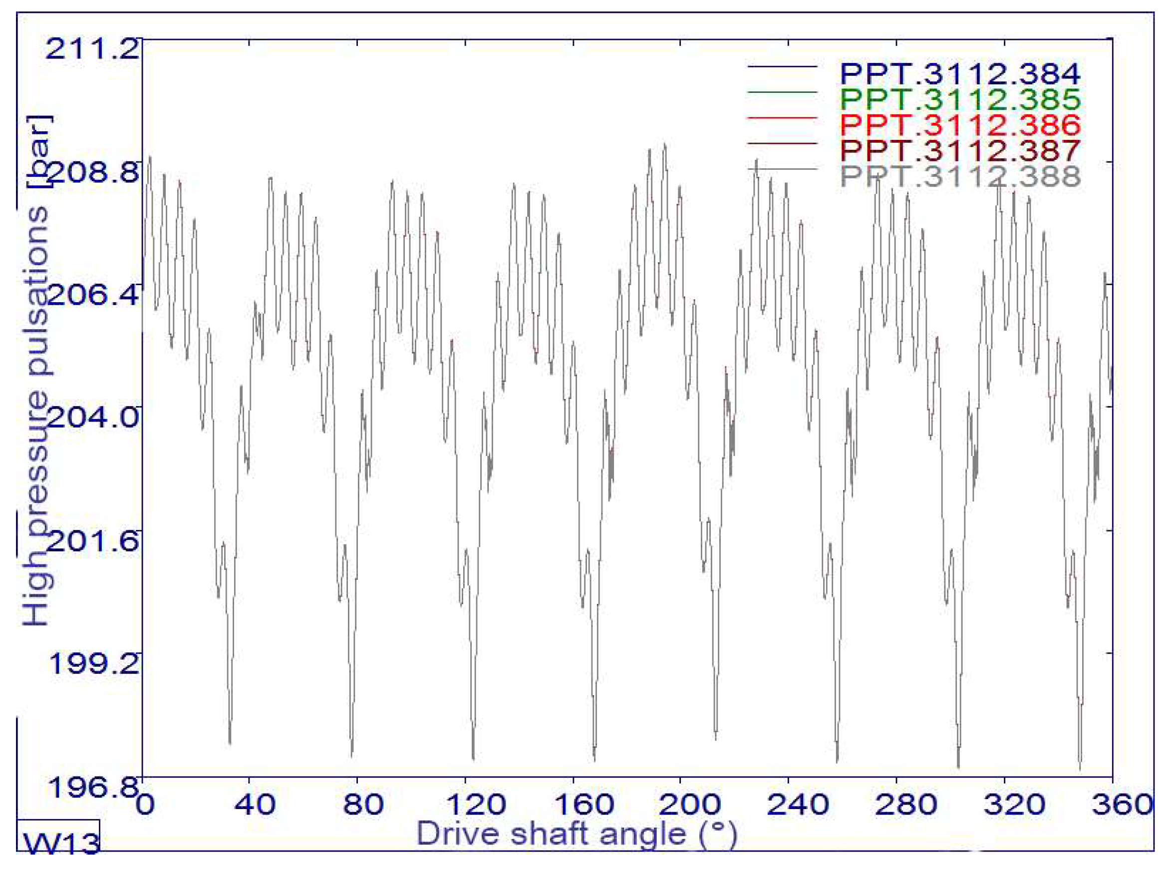
This diagram provides valuable insight into the operating performance of a reciprocating pump, showing how pressure varies over the cycle, which can help diagnose performance problems and optimize design parameters. The pressure rise and fall lines in
Figure 9 and
Figure 10 indicate pulsations, which can cause vibrations in the pump housing.
Figure 11 indicates the occurrence of high pressure pulsations as a result of the number of pump pistons (in this case 8 pistons).
5. Pump Housing Vibrations
Vibrations of the hydraulic pump housing, induced by piston operation, arise from several sources. The reciprocating motion of the pistons within the cylinders generates dynamic forces due to their acceleration and deceleration, directly exciting vibrations in the housing. Furthermore, non-uniform fluid flow, including pressure transients and flow direction changes, induces pressure fluctuations that contribute to these vibrations.
When the pump pressure drops below the vapor pressure of the liquid, vapor bubbles form and collapse, creating shock waves that can contribute to vibration. Materials and designs that provide damping can help reduce vibration. Proper mounting and isolation techniques can also mitigate the transmission of vibrations. When the vibration amplitudes of the hydraulic pump casing are measured with an accelerometer with a measuring range of 5 m/s², the output quantities include:
acceleration, as the primary output from the accelerometer experienced by the pump casing, measured in meters per second squared (m/s²).
speed, which is obtained by integrating acceleration data over time, as the speed of vibration, usually expressed in meters per second (m/s).
displacement as a further integration of the velocity data, which represents the total movement of the housing over the period, expressed in meters (m).
frequency components as a result of Fourier transform analysis of acceleration data expressed in hertz (Hz).
Sound pressure and vibration levels are often expressed in decibels to provide a logarithmic scale that can handle a wide range of pressures and vibrations.
The decibel level is calculated using the formula:
where are:
L – number of decibels
p – measured amplitude level
pref = 10 Kref - recommended reference level
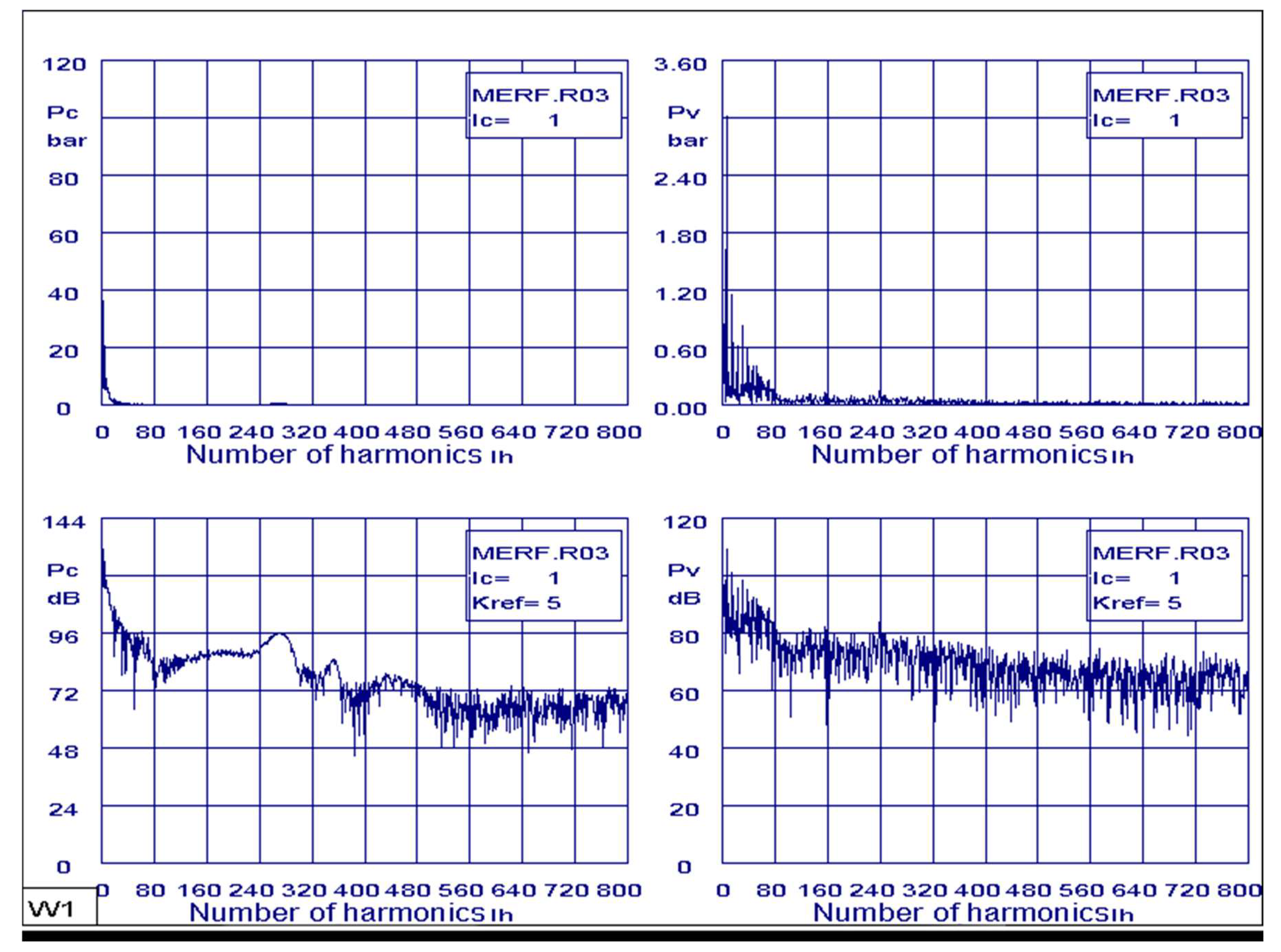
These output quantities can be used to assess the health and performance of a hydraulic pump by identifying problems such as imbalance, misalignment or other mechanical faults. The diagram illustrates the relationship between a series of harmonics and the corresponding pressure levels. Analysis of peaks in the frequency spectrum helps identify dominant vibration frequencies that may be correlated with operational anomalies or imbalances in pumps. It is important to relate the amplitude of vibrations at certain harmonics to the measured pressure. Significant changes in amplitude at certain harmonics may indicate problems such as cavitation, misalignment or mechanical wear.
Figure 12 presents the harmonic content of the pressure signals. Specifically,
Figure 12a,b show the cylinder pressure in bars and decibels, respectively, as a function of harmonic order. Similarly,
Figure 12c,d display the suction chamber pressure in bars and decibels, respectively, as a function of harmonic order.
Figure 12a presents the frequency spectrum of the hydraulic pump housing vibration, measured using an accelerometer with a full-scale range of 5 m/s². The spectrum illustrates the relationship between vibration amplitude and harmonic order. Peaks at specific harmonics suggest resonant frequencies or characteristic vibrational modes of the pump. The measurements, conducted across a range of operating conditions resulting in cylinder pressure variations from 0 to 200 bar, reveal a clear correlation between certain harmonics and pressure levels. The presence of anomalies or unexpected spikes in the spectrum may indicate mechanical issues such as imbalance, misalignment, or pump wear.
Figure 12b shows the frequency spectrum of the cylinder pressure, expressed in decibels (dB), as a function of harmonic order. The displayed range is 0 to 144 dB. Elevated pressure levels at specific harmonics, particularly those associated with cavitation or other operational inefficiencies, are evident as distinct peaks in the spectrum.
Figure 12c presents the frequency spectrum of the suction chamber pressure, with magnitude expressed in bars, as a function of harmonic order. The displayed pressure range is 0 to 3.6 bar. Peaks at specific harmonics suggest potential resonant frequencies or characteristic pressure oscillations within the pump. These measurements, acquired across a range of operating conditions, allow for analysis of the harmonic content to identify potential resonance issues..
Figure 12d presents the frequency spectrum of the suction chamber pressure, expressed in decibels (dB), as a function of harmonic order. The displayed range is 0 to 120dB. These dB levels represent the magnitude of the pressure fluctuations at each harmonic. Elevated dB levels at specific harmonics may indicate potential issues such as cavitation or mechanical imbalances within the pump. The analysis of these harmonics helps identify characteristic frequencies in the suction chamber pressure signal, which can be related to specific pump behaviors.
6. Conclusions
The research results of this study can be applied to optimize the design of axial piston pumps based on specific requirements (eg balancing compactness, cost and performance in hydraulic systems where noise reduction is critical). The importance of these results is relevant for industries where noise and vibration control is key and is particularly prominent in automotive, aerospace and industrial machinery.
To minimize structural loading on the pump casing, the relationship between pressure pulsations and transmitted vibrations was investigated, aiming to achieve a more uniform distribution of forces. The study demonstrated that increasing the number of pistons generally reduces pressure pulsations. Understanding the interrelationship between the number of pistons, pressure pulsations, and casing vibrations is crucial for designing more efficient and reliable axial piston pumps. Specifically, reducing pressure pulsations can enhance the performance and lifespan of both the pump and the connected hydraulic system.
All assumptions that could affect the generalization of the results were made during the simulation and modeling process and refer to idealized conditions (e.g., perfect fluid dynamics, specific operating range) and do not fully reflect variations in real conditions. Limited experimental data are related with experimental settings (e.g., using limited pump sizes, material limitations and lack of long-term performance testing).
The study is focused on specific operating conditions (eg specific flow rates or pressures), and it is important to note that results may vary outside of these ranges. An extension of the study is planned to take into account the effects of additional parameters such as fluid temperature, fluid viscosity and pump casing material properties on vibration and pulsation characteristics. The influence of parameters such as piston geometry, cylinder block size, would be the subject of future research on pressure pulsations and vibrations. Long-term experimental studies are planned to evaluate the effects of different numbers of pistons on pump durability and performance over extended operating periods, including the effect of wear. It is planned to use more sophisticated Computational Fluid Dynamics (CFD) or Finite Element Analysis (FEA) methods to simulate complex fluid-structure interactions in more detail.
The results of the study highlight the significant role that the number of pistons plays on the pressure pulsation and vibration characteristics of axial piston pumps, which has a direct impact on the performance and longevity of the hydraulic system. Optimizing the number of pistons is key to the development of axial piston pumps, specific hydraulic systems.
Author Contributions
For research articles with several authors, a short paragraph specifying their individual contributions must be provided. The following statements should be used “Conceptualization, M.R., L.S., S.M., N.Dj., R.P., J.L.Š.; methodology, M.R., L.S., S.M., N.Dj., R.P., J.L.Š.; software, M.R., L.S., S.M., N.Dj., R.P., J.L.Š.; validation, M.R., L.S., S.M., N.Dj., R.P., J.L.Š.; formal analysis, M.R., L.S., S.M., N.Dj., R.P., J.L.Š.; investigation, M.R., L.S., S.M., N.Dj., R.P., J.L.Š.; resources, M.R., L.S., S.M., N.Dj., R.P., J.L.Š.; data curation, M.R., L.S., S.M., N.Dj., R.P., J.L.Š.; writing—original draft preparation, M.R., L.S., S.M., N.Dj., R.P., J.L.Š.; writing—review and editing, M.R., L.S., S.M., N.Dj., R.P., J.L.Š.; visualization, M.R., L.S., S.M., N.Dj., R.P., J.L.Š.; supervision, M.R., L.S., S.M., N.Dj., R.P., J.L.Š.; project administration, M.R., L.S., S.M., N.Dj., R.P., J.L.Š.; funding acquisition, R.P. All authors have read and agreed to the published version of the manuscript. ”Please turn to the CRediT taxonomy for the term explanation. Authorship must be limited to those who have contributed substantially to the work reported.
Funding
This paper is funded by the University “Union-NikolaTesla”, Faculty of Information Technology and Engineering.
Institutional Review Board Statement
Not applicable.
Informed Consent Statement
Not applicable.
Data Availability Statement
Data are contained within the article.
Acknowledgments
The authors would like to thank Editor-in-Chief, Editor, and anonymous reviewers for their valuable reviews.
Conflicts of Interest
The authors declare no conflict of interest.
References
- Petrović:R. Mathematical Modelingand Experimental Research of Characteristic Parameters Hydrodynamic Processes of a Piston Axial Pump. Stroj. Vestn. —J. Mech. Eng. 2009, 55,222–229.
- Bech,T.; Olsen,S.; Klit,P. Design of Pumps for Water Hydraulic Systems. In Proceedings of the 6th Scandinavian International Conferenceon Fluid Power, SICFP’ 99,Tampere, Finland, 26–28 May 1999.
- Jourani,A.; Hagege,B.; Bouvier,S.; Bigerelle,M.; Zahouani,H. Influence of abrasive grain geometry on friction coefficient and wear rate in belt finishing.Tribol. Int. 2013, 59,30–37.
- Yang,H.; Yang,J.; Zhou,H. Research on materials of piston and cylinder of water hydraulic pump. Ind. Lubr. Tribol. 2003, 55,38–43.
- Vacca,A.; Franzoni,G. Hydraulic Fluid Power: Fundamentals, Applications, and Circuit Design; Wiley:Hoboken, NJ, USA, 2021.
- Akers,A.; Gassman,M.; Smith,R. Hydraulic Power System Analysis, 1sted.; CRC Press: Boca Raton, FL, USA, 2006. [CrossRef]
- Spencer,N.A. Design and Development of a Novel Test Method to Measure the Slipper / Swash plate Interface Fluid Film in a Positive Displacement Machine. Master’s Thesis, Purdue University,West Lafayette, IN, USA, 2014.
- Ham,Y.B.; Lee,Y.B.; Park,K.M.; Choi,B.O. A study on the application of birfield joint to a water hydraulic piston pump for lowleakage and low friction pumping. In Proceedings of the 6th JFPS International Symposium on Fluid Power,Tsukuba, Japan, 7–10 November 2005.
- Canbulut,F.; Sinanoğlu,C.; Koc,E. Experimental analysis of frictional power loss of hydrostatic slipper bearings. Ind. Lubr. Tribol. 2009, 61,123–131.
- Załuski,P. Experimental Research of an Axial Piston Pump with Displaced Swash Plate Axis of Rotation. In Advances in Hydraulic and Pneumatic Drives and Control NSHP 2020; Springer: Berlin/ Heidelberg, Germany, 2020; 35–145.https://doi.org/10.1007/978-3-030-59509-8_12.
- Manring,N.D.; Wray,C.L.; Dong,Z.L. Experimental studies on the performance of slipper bearings with in axial-piston pumps. J. Tribol. 2004, 126, 511–518.
- Panda, J.P.; Warrior,H.V. Numerical Studies on Drag Reduction of An Axisymmetric Body of Revolution With Anti turbulence Surface. J. Offshore Mech. Arct. Eng. 2021, 143(6). [CrossRef]
- Stosiak, M.; Karpenko, M. Dynamics of Machines and Hydraulic Systems. In Mechanical Vibrations and Pressure Pulsations; Springer: Cham, Switzerland, 2024; ISBN 978-3-031-55524-4.
- Karpenko, M. Aircraft hydraulic drive energy losses and operation delay associated with the pipeline and fitting connections. Aviation, 2024, 28(1), 1–8. [CrossRef]
- Petrović, R.; Ivanović, P.;Glavčić, Z.;Savković, M. Experimental research of characteristic parameters of hydrodinamic processes in a piston axial pump”, VI International Triennial Conference Heavy Machinery – HM’08,Kraljevo,2008.
- Petrović, R.; Banaszek, A.; Andjelković, M.; Qananah, H.R.; Alnagasa, K.A. Experimental Tests of the Piston Axial Pump with Constant Pressure and Variable Flow. Designs 2024, 8, 5. [CrossRef]
- Petrović; R.;Pezdirnik, J.; Banaszek, A.; Đuričić,Lj.Influence of compressibility of working fluid on hydrodynamic processes in the axial piston pump with combined distribution/flow of working fluid.Proceedings of 2011,DOI: 10.1109/FPM.2011.6045784, International Conference on Fluid Power and Mechatronics 17-20 August 2011, Beijing, China.
- Wang, S. Generic Modeling and Control of an Open-Circuit Piston Pump—Part I: Theoretical Model and Analysis. J. Dyn. Syst. Meas. Control 2016, 138, 041004.
- Wang, S. Generic Modeling and Control of an Open-Circuit Piston Pump—Part II: Control Strategies and Designs. J. Dyn. Syst. Meas. Control 2016, 138, 041005.
- Koivumäki, J.; Mattila, J. Adaptive and nonlinear control of discharge pressure for variable displacement axial piston pumps. J. Dyn. Syst. Meas. Control 2017, 139, 101008.
|
Disclaimer/Publisher’s Note: The statements, opinions and data contained in all publications are solely those of the individual author(s) and contributor(s) and not of MDPI and/or the editor(s). MDPI and/or the editor(s) disclaim responsibility for any injury to people or property resulting from any ideas, methods, instructions or products referred to in the content. |
© 2025 by the authors. Licensee MDPI, Basel, Switzerland. This article is an open access article distributed under the terms and conditions of the Creative Commons Attribution (CC BY) license (http://creativecommons.org/licenses/by/4.0/).