
Submitted:
03 January 2025
Posted:
08 January 2025
You are already at the latest version
Abstract
The energy loss in iron is valuable knowledge due to its extended use, technological applications and open topics in fundamental physics. The electronic structure of solid Fe is challenging, being the first of the groups of transition metals with some of the d-electrons promoted to the conduction band while others remain bound. The low energy description, the deviation from velocity proportionality at low impact energies, and the contribution of the loosely bound d-electrons to the energy loss are active featured fields about the stopping in Fe. Very recent TDDFT calculations have been compared with the first stopping measurements in steel, showing surprisingly good agreement. In the present work, we applied a recent model based on the momentum distribution function of the d-electrons to the case of Fe. The comparison with other models is discussed, as well as with the experimental data. We also highlight discrepancies among data sets regarding the stopping maximum and the need for new experimental efforts.
Keywords:
stopping power
; iron
; transition metal
; d-electrons
1. Introduction
The interaction of ions with transition metals is of significant interest in nuclear materials science, plasma physics, and energy research [1]. In particular, the energy loss of ions in inelastic collisions with the target electrons (electronic stopping power) is essential to understanding radiation damage, hydrogen embrittlement, ion implantation, and all processes related to electron structure and dynamics. The extension of ion-target systems of interest is vast, making stopping power an active field, experimentally and theoretically.
Different models have been developed over the years, from the historical works [2,3] to the recent times [4], going through the free electron gas models (FEG) [5,6,7,8] to the real-time time-dependent density functional theory (TDDFT) [9,10,11,12], and real-time solutions of Schrödinger equation [13], the binary collisional formulations [14,15,16] and the quantum dielectric formalisms [17,18,19] based on Lindhard and Mermin works [20,21]. All the approximations have different energy regions of validity and limitations in the number of active electrons to be considered, making the electronic stopping power a still open field, with the low-energy region and the stopping maximum being challenging and sensitive subjects.
Iron is widely used in industrial and technological applications. However, its electronic energy loss is experimentally weakly known. The stopping measurements for H and He ions in Fe were made more than thirty years ago, with discrepant groups of values around the stopping maximum (see, for example, [22,23] and [24] for H, and [25] and [26] for He.
Transition metals exhibit complex electronic structures that influence energy-loss processes. The first ones, groups 3–7 of the periodic table, are characterized by all their valence d and s electrons in the conduction band, which can be described as an FEG. In contrast, in the later transition metals, groups 8–11, a fraction of the d-electrons remains localized and is expected to play a key role in the energy loss even at very low impact energies [27]. In this energy region, the stopping power is expected to have a linear dependence on the ion velocity. However, a departure from proportionality has been suggested for the transition metals with almost filled d-orbital (groups 10 and 11) [27,28,29,30].
This work performs a detailed analysis of the stopping power of hydrogen in Iron, aiming to describe it in energy range. We pay special attention to the low energy stopping power, intending to elucidate if the mentioned deviation the linear dependence with the velocity is also present in the case of Iron.
We employ a recent non-perturbative model developed by our group [31] to describe the quasi-free d-electron contribution to the stopping power. The total electronic stopping is calculated by including the response of the FEG, the sub-valence d-orbital, and the deep shells. We compare the present results with all data available for H in Fe as compiled in the IAEA stopping power database [32], and with recent measurements in steel [33]. We only describe the electronic stopping power; the nuclear stopping is not included, and we assume that the low-energy experimental values with have sustained it.
2. Theoretical Models
In the present study, we describe the electronic stopping power in the solid target, considering that the response of electrons to the ion passage differs for the valence electrons of the metals, the loosely bound d-electrons, and the inner shells. Therefore, we use different formalisms for these three cases.
The valence electrons of metals are approximated as an FEG, with a homogeneous momentum distribution within the Fermi sphere. The FEG may have binary and collective excitations in response to the ion passage, and its contribution to the total stopping power is the main one at low-impact energies. As a first-order approximation, the FEG model predicts a linear dependence on the impact velocity [34]. More detailed models [11,35] show small fluctuations on the slope. In this contribution, we use the non-perturbative model proposed in [35] based on a screened potential that depends on the ion velocity and the density of electrons in the FEG and verifies the cusp condition for the induced density of electrons following the ion passage. The FEG stopping cross-section as a function of the impact velocity v is given by [35,36]
where is the density of target atoms, is the relative velocity, is the electron momentum, is the Heaviside step function representing the homogeneous momentum distribution, is the Fermi momentum, and is the transport cross-section in the screened potential [35]. The model described by Eq. (1) is binary collisional; no collective or plasmon excitations of the FEG are included. Plasmons are known to contribute at intermediate to high impact velocities, so we employ the non-perturbative model in [35] for low impact velocities (i.e. ) and combine it with the dielectric formalism by Mermin-Lindhard [21] for higher velocities (see [37] for details).
For the contribution of the quasi-free d-electrons of the transition metals, we employed a recently developed model [31] based on the inhomogeneous momentum distribution function of the d-orbital given by
with being the Fourier transform of the wave functions , normalized to the number of electrons in the outer -subshell. In the case of Fe, the wave function employed is the Slater-type orbital expansion of the Roothaan-Hartree-Fock ground state by Bunge [38]. By using this expansion, the Fourier transform is analytical employing Flannery-Levy integrals [39]. The distribution function for the case of electrons is
where the parameters , are the coefficients of the Slater expansion, and comes from the normalization of the wave function to the number of electrons. The d-contribution to the electronic stopping cross-section, is then expressed as
where the transport cross-section is calculated using the same velocity-dependent potential proposed in ref. [35] with the screening of a constant density of d-electrons .
The inner-shell contributions to the stopping power are crucial at high-impact energies. In the present work, even the deep K-shell is considered. To this end, we employed the shellwise local plasma approximation with Levine-Mermin dielectric function (SLPA-LM) [18,37]. The stopping cross section for a bare ion with charge , moving with velocity v, is obtained by adding the independent contributions of each j sub-shell given by
The j-energy-loss function is expressed as
with being the Levine–Mermin (LM) dielectric response function [37], which explicitly includes the binding energy , the local electron density of the atomic j sub-shell, , and a local damping .
The total electronic stopping cross section is calculated by adding the three independent the contributions Equations (1), (4), and (5)
with in the case of Fe.
The stopping power can also be expressed in terms of the friction parameter . The friction coefficient is a sensitive parameter, giving an expanded view of the energy loss problem. As mentioned above, the stopping power is expected to show a linear dependency at low-impact velocities, so should be a constant. We will return to this in the next section, given the theoretical-experimental comparison.
3. Results and Discussion
The atomic configuration of Fe is . As mentioned above, the latter transition metals, such as Fe, have some bound d-electrons promoted to the conduction band, while others remain bound to the target nucleus. Knowing how many electrons are part of the FEG, , and how many remain bound in the d-subshell, , is crucial for describing the energy loss. To this end, we analyzed the Hartree-Fock results for the orbital binding energies by Bunge et al. [38] and the data from reflection electron energy-loss spectroscopy in solids by Werner et al. [40].
The theoretical binding energies of Fe are displayed in Figure 1. These values for are included in the SLPA-LM calculations for the inner shells given by Equation (6). It is worth mentioning that Bunge [38] calculations correspond to atoms (gas target), while we are interested in solid Iron. For this reason, we also include in this figure the experimental binding energies in solids compiled in [41]. The agreement is good, except for the -subshell, for which the theoretical value is larger than the experimental one. No experimental binding energies were for the and electrons in solid Fe. This fact is coherent with these electrons in the conduction band of the metal or with a minimal binding energy. To analyze this point, we include in Figure 1 the Fermi energy corresponding to 4 electrons in the FEG. This value is very close to the orbital energy by Bunge [38].
Werner et al. [40] experimental data in solids was analyzed to have a closer approach to the FEG values. The experimental plasmon frequency and dump were obtained from the first significant peak and width of the energy loss function (ELF) in Ref. [40], being and . The experimental number of electrons in the FEG can be inferred from . We define as the closest integer number to that value. Based on these values, we consider , consistent with a conduction band. Then, the plasmon frequency is , , the Fermi velocity is , and the Fermi energy .
We calculated the stopping cross section of H in Fe by considering the independent FEG, and inner-shell contributions, as explained in Section 2.
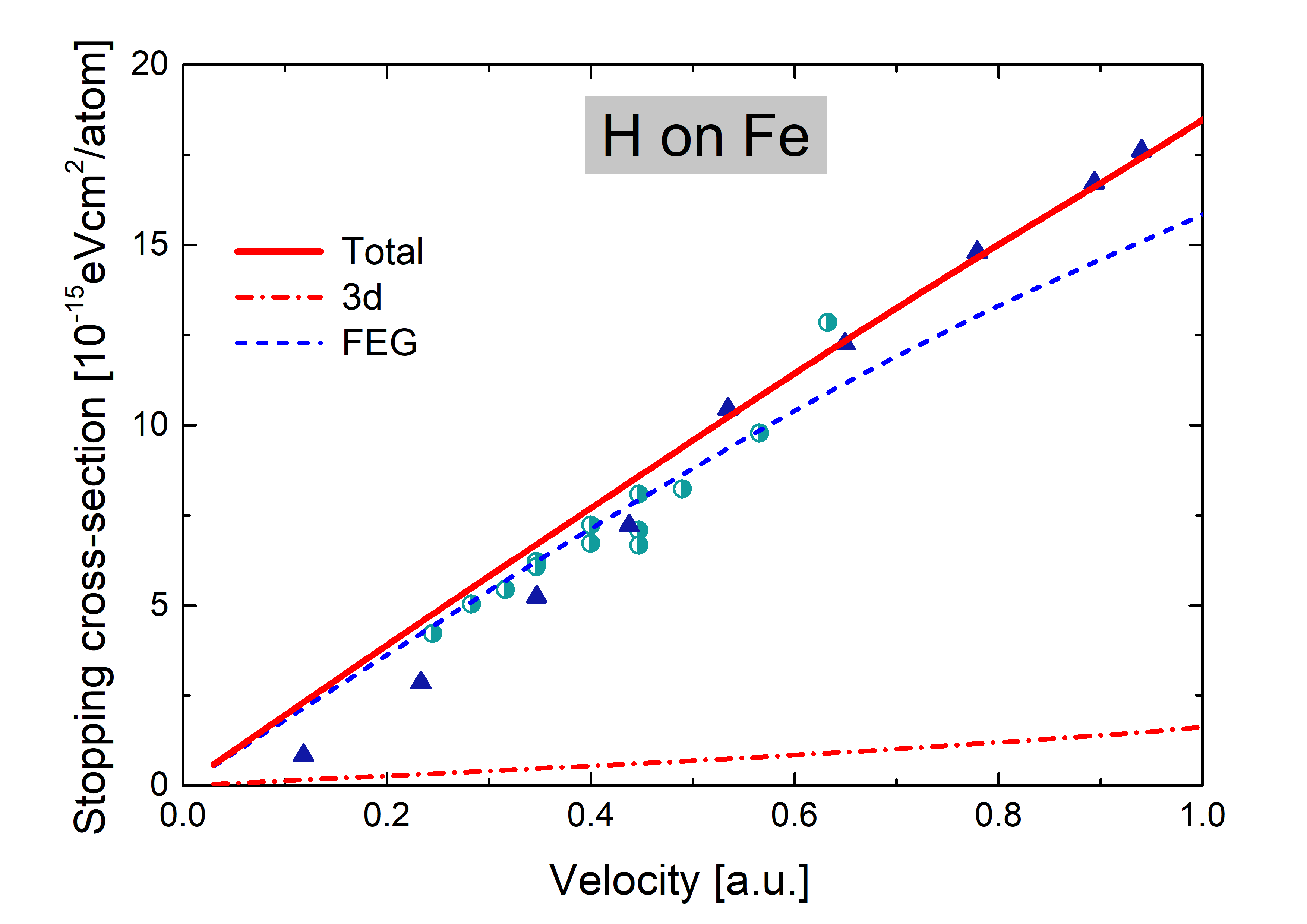
In Figure 2, the total electronic stopping cross-section, the FEG and contributions are displayed as a function of the ion impact velocity for . The only experimental data for protons in Fe at these low velocities are the measurements by Arkhipov and Gott in 1969 [42], which are nicely described by the present total values. It can be noted that the FEG stopping cannot explain the data for , highlighting the importance of the contribution at such low velocities. In the theoretical experimental comparison, we also include the recent measurements in eurofer97 by Uppsala group [33]. This comparison is based on the fact that Fe is the leading steel component. For , our results slightly overestimate the experimental values.
The description of low-impact velocities is amplified by calculating the friction parameter Q should be constant for as long as the linear dependence with the velocity is valid. In Figure 3, we display the present results considering the total electronic stopping cross-sections and compare them with very recent TDDFT results (off-channeling) by Zhao et al. [11]. Our curve describes the experimental values by Arkhipov (1969) [42] above and by Mertens (1982), while Zhao et al. curve [11] is closer to the data by White (1969) and the recent measurements by Shams-Latifi et al. (2024) [33]. Regarding the linear behaviour, both curves are almost constant in the velocity range up to , with our values being % above TDDFT ones. This comparison is very good, considering the accuracy of real-time TDDFT calculations and the sensitivity of the friction comparison.
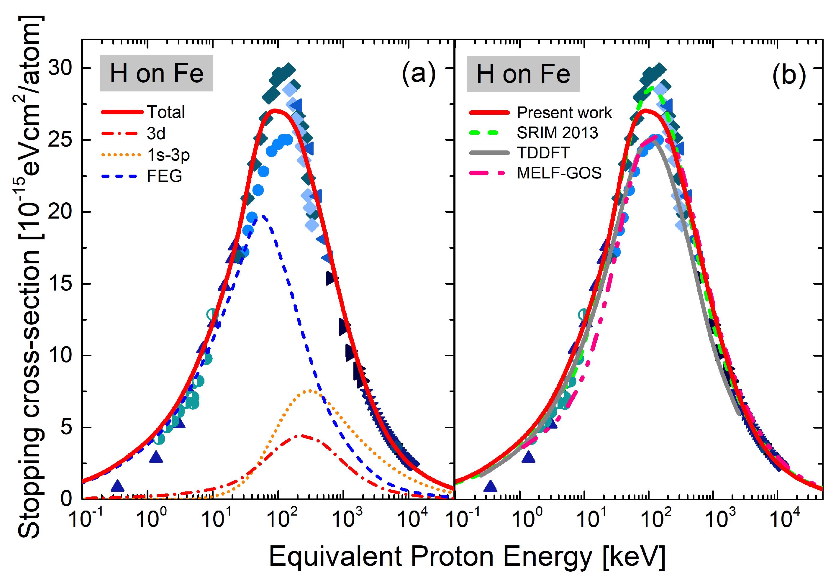
In Figure 4, we evaluate the present results in an extended energy region by presenting the electronic stopping cross-section as a function of the impact energy in the range keV/u. Figure 4a shows the results obtained in this work for the total stopping, the FEG, and inner shell contributions. The importance of the ionization to the energy loss is remarkable above 40 keV/u. Present total values agree very well with the experimental data except in the region keV/u, around the stopping maximum. Only two experimental groups measured in this energy region, White and Mueller in 1969 [24], obtained the lowest value, while Mertens and Krist in 1982 [22,23] measured a higher maximum. Despite being closer to [22,23], our present results do not follow any of the two peaks. Having new stopping measurements in Fe around the maximum would be valuable.
In Figure 4b, we compare the present total stopping cross-section with other theoretical results: the Mermin Energy-Loss Function–Generalized Oscillator Strength (MELF-GOS) values by de Vera et al. [43]; and the TDDFT ones by Zhao et al. [11]. We also included the semiempirical srim curve [44]. The MELF-GOS results included in Figure 4b are based on the optical ELF by Werner et al. [40], analogously as our calculations for the FEG. It is a perturbative model, so the observed underestimation of the data at low energies is expected. Above 30 keV/u, it describes very well the data, following the lower maximum in [24]. For energies greater than 200 keV/u, MELF-GOS [43] values agree with the present results. The TDDFT calculations in [11] consider 14 active electrons, . The obtained results are remarkable at low energies but are shown low at high energies due to the lack of deeper subshells. As expected, the semiempirical srim accurately describes most data, following the higher maximum [22,23,45]. The results in Figure 4 demonstrate that the strength of our proposal is that it is a complete theoretical model that allows us to describe the stopping power from very low energies to high but non-relativistic ones.
4. Conclusions
In this work, we examine the energy loss of protons in Iron. We analyze the electron contribution using a recent non-perturbative model based on the inhomogeneous momentum distribution. Although this contribution is essential at low-impact velocities, we found that its inclusion does not represent a departure from the linear dependence of the stopping power with the velocity. Moreover, the friction parameter obtained is almost constant for . The total electronic stopping power is calculated by adding FEG, and contributions. The present results show good agreement with the experimental values in the energy range keV/u due to the non-perturbative model at low energies and the dielectric formalism that allows us to describe the intermediate to high energies, including all the deep shells. It can be concluded that the present proposal manages to describe the energy loss of protons in Iron in a wide range of energies.
Disagreement between experimental datasets and theoretical results is noted around the stopping maximum, making the present status of the knowledge still open. It is remarkable that Fe is so under-measured. The stopping power data of protons in Fe are thirty years old, with the values around the maximum being forty years old. We emphasize the need for new stopping measurements in such a widely used material for H and also for He ions since similar data scattering around the maximum was observed in both cases.
Funding
The following institutions of Argentina financially support this research: the Consejo Nacional de Investigaciones científicas y Técnicas (CONICET) by the project PIP11220200102421CO, the Agencia Nacional de Promoción Científica y Tecnológica (ANPCyT) by the project PICT-2020-SERIE A-01931.
References
- Montanari, C.; Dimitriou, P.; Marian, L.; Mendez, A.; Peralta, J.; Bivort-Haiek, F. The IAEA electronic stopping power database: Modernization, review, and analysis of the existing experimental data. Nuclear Instruments and Methods in Physics Research Section B: Beam Interactions with Materials and Atoms 2024, 551, 165336. [Google Scholar] [CrossRef]
- Bethe, H. Zur Theorie des Durchgangs schneller Korpuskularstrahlen durch Materie. Annalen der Physik 1930, 397, 325–400. [Google Scholar] [CrossRef]
- Bohr, N. The penetration of atomic particles through matter; Munksgaard Copenhagen, 1948.
- Sigmund, P.; Schinner, A. Progress in understanding heavy-ion stopping. Nuclear Instruments and Methods in Physics Research Section B: Beam Interactions with Materials and Atoms 2016, 382, 15–25, The 21st International workshop on Inelastic Ion Surface Collisions (IISC-21). [Google Scholar] [CrossRef]
- Ashcroft, N.W.; Mermin, N.D. Solid State Physics; Holt, Rinehart and Winston, New York, 1976.
- Ritchie, R.H. Interaction of Charged Particles with a Degenerate Fermi-Dirac Electron Gas. Phys. Rev. 1959, 114, 644–654. [Google Scholar] [CrossRef]
- Ferrell, T.L.; Ritchie, R.H. Energy losses by slow ions and atoms to electronic excitation in solids. Phys. Rev. B 1977, 16, 115–123. [Google Scholar] [CrossRef]
- Echenique, P.M.; Flores, F.; Ritchie, R.H. , Dynamic Screening of Ions in Condensed Matter; Academic Press, 1990; Vol. 43, Solid State Physics, pp. 229–308. [CrossRef]
- Quashie, E.E.; Saha, B.C.; Correa, A.A. Electronic band structure effects in the stopping of protons in copper. Phys. Rev. B 2016, 94, 155403. [Google Scholar] [CrossRef]
- Li, C.K.; Guo, X.; Xue, J.M.; Zhang, F.S. Electronic stopping power of protons in platinum: Direct valence and inner-shell-electron excitations from first-principles calculations. Phys. Rev. A 2023, 107, 052814. [Google Scholar] [CrossRef]
- Zhao, X.D.; Mao, F.; Deng, H. Electronic stopping of iron for protons and helium ions from first-principles calculations. Phys. Rev. A 2024, 109, 032807. [Google Scholar] [CrossRef]
- Matias, F.; Grande, P.L.; Koval, N.E.; Shorto, J.M.B.; Silva, T.F.; Arista, N.R. Deeper-band electron contributions to stopping power of silicon for low-energy ions. The Journal of Chemical Physics 2024, 161, 064310. [Google Scholar] [CrossRef]
- Cabrera-Trujillo, R.; Sabin, J.; Deumens, E.; Öhrn, Y. Dynamical Processes in Stopping Cross Sections. In Theory of the Interaction of Swift Ions with Matter. Part 1; Academic Press, 2004; Vol. 45, Advances in Quantum Chemistry, pp. 99–124. [CrossRef]
- Schiwietz, G.; Grande, P. Stopping of protons – Improved accuracy of the UCA model. Nuclear Instruments and Methods in Physics Research Section B: Beam Interactions with Materials and Atoms 2012, 273, 1–5, 20th International Conference on Ion Beam Analysis. [Google Scholar] [CrossRef]
- Schinner, A.; Sigmund, P. Expanded PASS stopping code. Nuclear Instruments and Methods in Physics Research Section B: Beam Interactions with Materials and Atoms 2019, 460, 19–26. [Google Scholar] [CrossRef]
- Alcocer-Ávila, M.E.; Quinto, M.A.; Monti, J.M.; Rivarola, R.D.; Champion, C. Proton transport modeling in a realistic biological environment by using TILDA-V. Scientific Reports 2019, 9, 14030. [Google Scholar] [CrossRef] [PubMed]
- Abril, I.; Garcia-Molina, R.; Denton, C.D.; Pérez-Pérez, F.J.; Arista, N.R. Dielectric description of wakes and stopping powers in solids. Phys. Rev. A 1998, 58, 357–366. [Google Scholar] [CrossRef]
- Montanari, C.C.; Miraglia, J.E. The Dielectric Formalism for Inelastic Processes in High-Energy Ion–Matter Collisions. In Advances in Quantum Chemistry: Theory of Heavy Ion Collision Physics in Hadron Therapy; Belkic, D., Ed.; Elsevier: New York, 2013; Vol. 2, chapter 7, pp. 165–201. [Google Scholar] [CrossRef]
- de Vera, P.; Abril, I.; Garcia-Molina, R. Energy Spectra of Protons and Generated Secondary Electrons around the Bragg Peak in Materials of Interest in Proton Therapy. Radiation Research 2018, 190, 282–297. [Google Scholar] [CrossRef]
- Lindhard, J. On the properties of a gas of charged particles. K. Dan. Vidensk. Selsk. Mat.-Fys. Medd. 1954, 28, 0. [Google Scholar]
- Mermin, N.D. Lindhard Dielectric Function in the Relaxation-Time Approximation. Phys. Rev. B 1970, 1, 2362–2363. [Google Scholar] [CrossRef]
- Mertens, P.; Krist, T. Electronic stopping cross sections for 30–300 keV protons in materials with 23≤Z2≤30. Nuclear Instruments and Methods in Physics Research 1982, 194, 57–60. [Google Scholar] [CrossRef]
- Mertens, P.; Krist, T. Stopping ratios for 30–330 keV ions with 1≤Z1≤5. Journal of Applied Physics 1982, 53, 7343–7349. [Google Scholar] [CrossRef]
- White, W.; Mueller, R.M. Electronic Stopping Cross Sections for 1H and 4He Particles in Cr, Mn, Co, Ni, and Cu at Energies near 100 keV. Phys. Rev. 1969, 187, 499–503. [Google Scholar] [CrossRef]
- Baglin, J.; Chu, W. Stopping power of 0.3–2.6 MeV 4He ions in Fe and Ni. Nuclear Instruments and Methods 1978, 149, 695–699. [Google Scholar] [CrossRef]
- Chu, W.K.; Powers, D. Alpha-Particle Stopping Cross Section in Solids from 400 keV to 2 MeV. Phys. Rev. 1969, 187, 478–490. [Google Scholar] [CrossRef]
- Cantero, E.D.; Lantschner, G.H.; Eckardt, J.C.; Arista, N.R. Velocity dependence of the energy loss of very slow proton and deuteron beams in Cu and Ag. Phys. Rev. A 2009, 80, 032904. [Google Scholar] [CrossRef]
- Markin, S.N.; Primetzhofer, D.; Prusa, S.; Brunmayr, M.; Kowarik, G.; Aumayr, F.; Bauer, P. Electronic interaction of very slow light ions in Au: Electronic stopping and electron emission. Phys. Rev. B 2008, 78, 195122. [Google Scholar] [CrossRef]
- Jorge, E. Valdés, P.V.; Esaulov, V.A. Energy losses of slow ions traveling through crystalline solids and scattered on crystalline surfaces. Radiation Effects and Defects in Solids 2016, 171, 60–76. [Google Scholar] [CrossRef]
- Goebl, D.; Roth, D.; Bauer, P. Role of d electrons in electronic stopping of slow light ions. Physical Review A - Atomic, Molecular, and Optical Physics 2013, 87, 062903. [Google Scholar] [CrossRef]
- Peralta, J.P.; Mendez, A.M.P.; Mitnik, D.M.; Montanari, C.C. The d-electron contribution to the stopping power of transition metals. Submitted to Phys. Rev. A, in progress. [CrossRef]
- IAEA. Electronic Stopping Power of Matter for Ions, https://www-nds.iaea.org/stopping/, 1928–2024.
- Shams-Latifi, J.; Pitthan, E.; Primetzhofer, D. Experimental electronic stopping cross-section of EUROFER97 for slow protons, deuterons and helium ions. Radiation Physics and Chemistry 2024, 224, 112073. [Google Scholar] [CrossRef]
- Fermi, E.; Teller, E. The Capture of Negative Mesotrons in Matter. Phys. Rev. 1947, 72, 399–408. [Google Scholar] [CrossRef]
- Montanari, C.C.; Miraglia, J.E. Low- and intermediate-energy stopping power of protons and antiprotons in solid targets. Phys. Rev. A 2017, 96, 012707. [Google Scholar] [CrossRef]
- Nagy, I.; Bergara, A. A model for the velocity-dependent screening. Nuclear Instruments and Methods in Physics Research Section B: Beam Interactions with Materials and Atoms 1996, 115, 58–61. [Google Scholar] [CrossRef]
- Peralta, J.P.; Fiori, M.; Mendez, A.M.P.; Montanari, C.C. Stopping-power calculations and the Levine-Mermin dielectric function for inner shells. Phys. Rev. A 2022, 105, 062814. [Google Scholar] [CrossRef]
- Bunge, C.; Barrientos, J.; Bunge, A. Roothaan-Hartree-Fock Ground-State Atomic Wave Functions: Slater-Type Orbital Expansions and Expectation Values for Z = 2–54. Atomic Data and Nuclear Data Tables 1993, 53, 113–162. [Google Scholar] [CrossRef]
- Flannery, M.R.; Levy, H., I. Simple Analytic Expression for General Two-Center Coulomb Integrals. The Journal of Chemical Physics 1969, 50, 2938–2940. [Google Scholar] [CrossRef]
- Werner, W.S.M.; Glantschnig, K.; Ambrosch-Draxl, C. Optical Constants and Inelastic Electron-Scattering Data for 17 Elemental Metals. Journal of Physical and Chemical Reference Data 2009, 38, 1013–1092. [Google Scholar] [CrossRef]
- Williams, G.P. , Electron Binding Energies of the Elements; CRC Handbook of Chemistry and Physics, CRC Press, 2014; chapter 10, pp. 200–205.
- Arkhipov, E.P.; Gott, Y.V. Soviet Journal of Experimental and Theoretical Physics 1969, 29, 615. 29.
- de Vera, P.; Abril, I.; Garcia-Molina, R. Electronic cross section, stopping power and energy-loss straggling of metals for swift protons, alpha particles and electrons. Frontiers in Materials 2023, 10. [Google Scholar] [CrossRef]
- Ziegler, J.F. SRIM, http://www.srim.org/, 2013.
- Bader, M.; Pixley, R.E.; Mozer, F.S.; Whaling, W. Stopping Cross Section of Solids for Protons, 50–600 KeV. Phys. Rev. 1956, 103, 32–38. [Google Scholar] [CrossRef]
- Ishiwari, R.; Shiomi, N.; Shirai, S.; Uemura, U. Stopping powers of Al, Ti, Fe, Cu, Mo, Ag, Sn, Ta and Au for 7.2 MeV protons. Physics Letters A 1974, 48, 96–98. [Google Scholar] [CrossRef]
- Ishiwari, R.; Shiomi, N.; Sakamoto, N. Stopping powers of Be, Al, Ti, V, Fe, Co, Ni, Cu, Zn, Mo, Rh, Ag, Sn, Ta, Pt and Au for 6.75 MeV protons. Physics Letters A 1979, 75, 112–114. [Google Scholar] [CrossRef]
- Andersen, H.H.; Hanke, C.C.; Simonsen, H.; Sørensen, H.; Vajda, P. Stopping Power of the Elements Z=20 Through Z=30 for 5–12-MeV Protons and Deuterons. Phys. Rev. 1968, 175, 389–395. [Google Scholar] [CrossRef]
- Tiedeakatemia, S. Annales Academiae Scientiarum Fennicae: Physica. Series A.. VI; Annales Academiae Scientiarum Fennicae: Physica, Suomalainen Tiedeakatemia, 1971. [Google Scholar]
- Shiomi-Tsuda, N.; Sakamoto, N.; Ishiwari, R. Stopping powers of Be, Al, Ti, V, Fe, Co, Ni, Cu, Zn, Mo, Rh, Ag, Sn, Ta, Pt and Au for 13 MeV deuterons. Nuclear Instruments and Methods in Physics Research Section B: Beam Interactions with Materials and Atoms 1994, 93, 391–398. [Google Scholar] [CrossRef]
Figure 1.
(Color online) Electron binding energies of Fe. Hartree-Fock results by Bunge [38], blue-line and triangles; experimental values from ref. [41], empty circles; Fermi energy level, dashed red line.
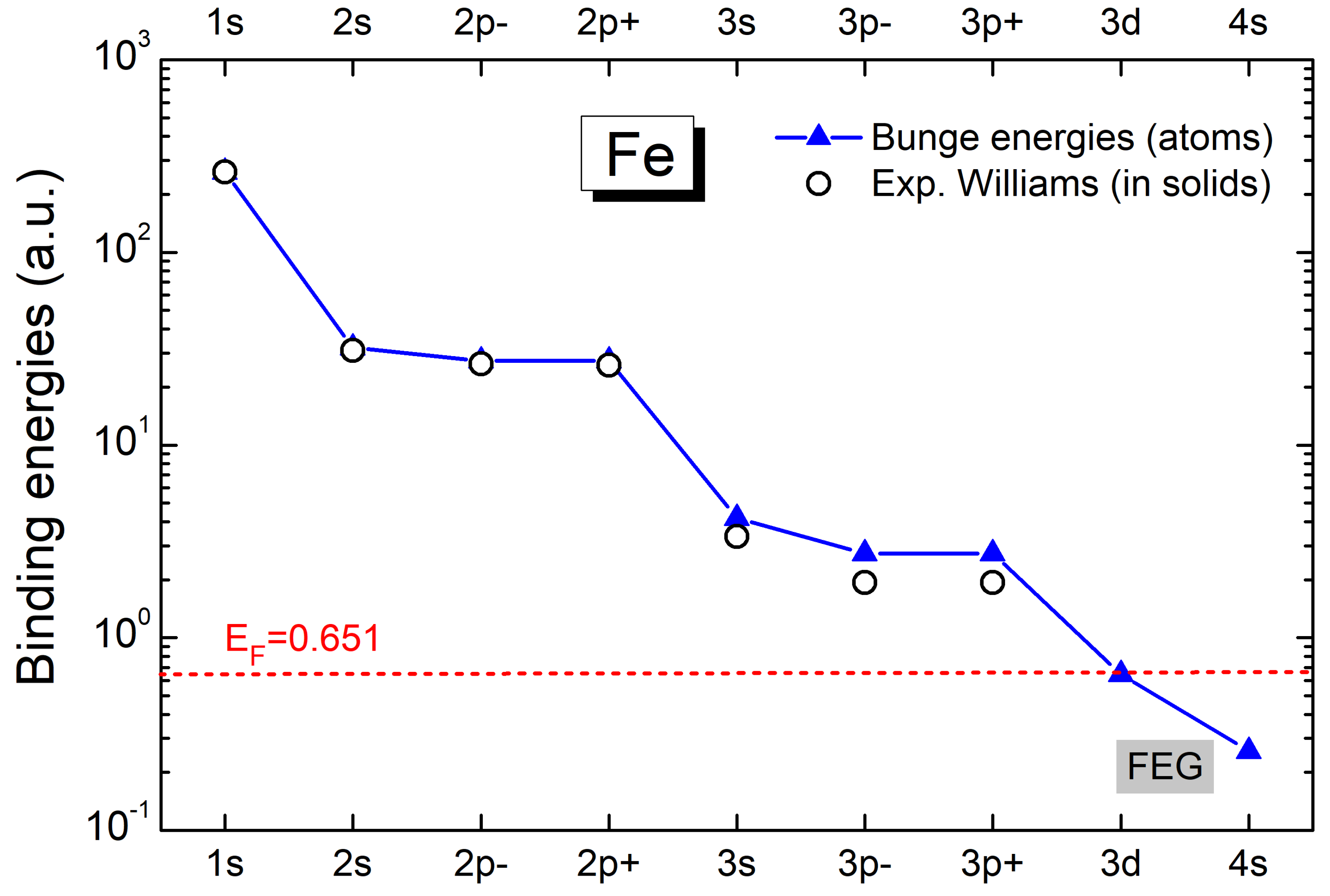
Figure 2.
(Color online) Low-energy electronic stopping cross-section of Fe for H as a function of the impact velocity. Curves: present results for total stopping, red solid line; d-electron contribution, red dashed-dot line; FEG stopping, blue dashed line. Symbols: ▴ [42]. Also included ◑ [33], for steel (eurofer97).
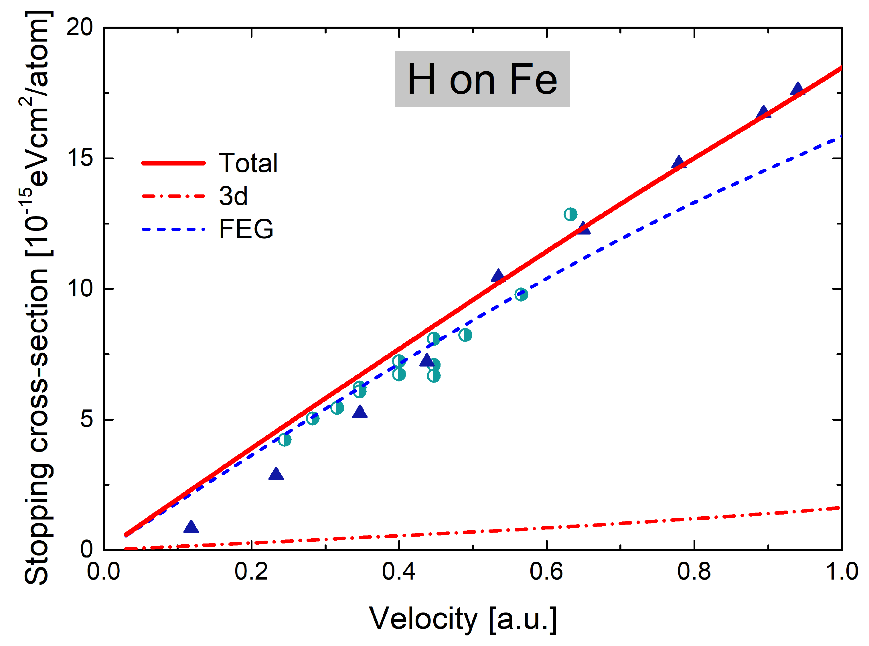
Figure 3.
(Color online) Friction parameter of Fe for H as a function of the impact velocity. Curves: thick red-solid line, present total stopping; thin grey-solid line, TDDFT results by Zhao [11]. Symbols: ▴ [42], • [24], ⧫ [22]. Also included ◑ [33] for steel (eurofer97).
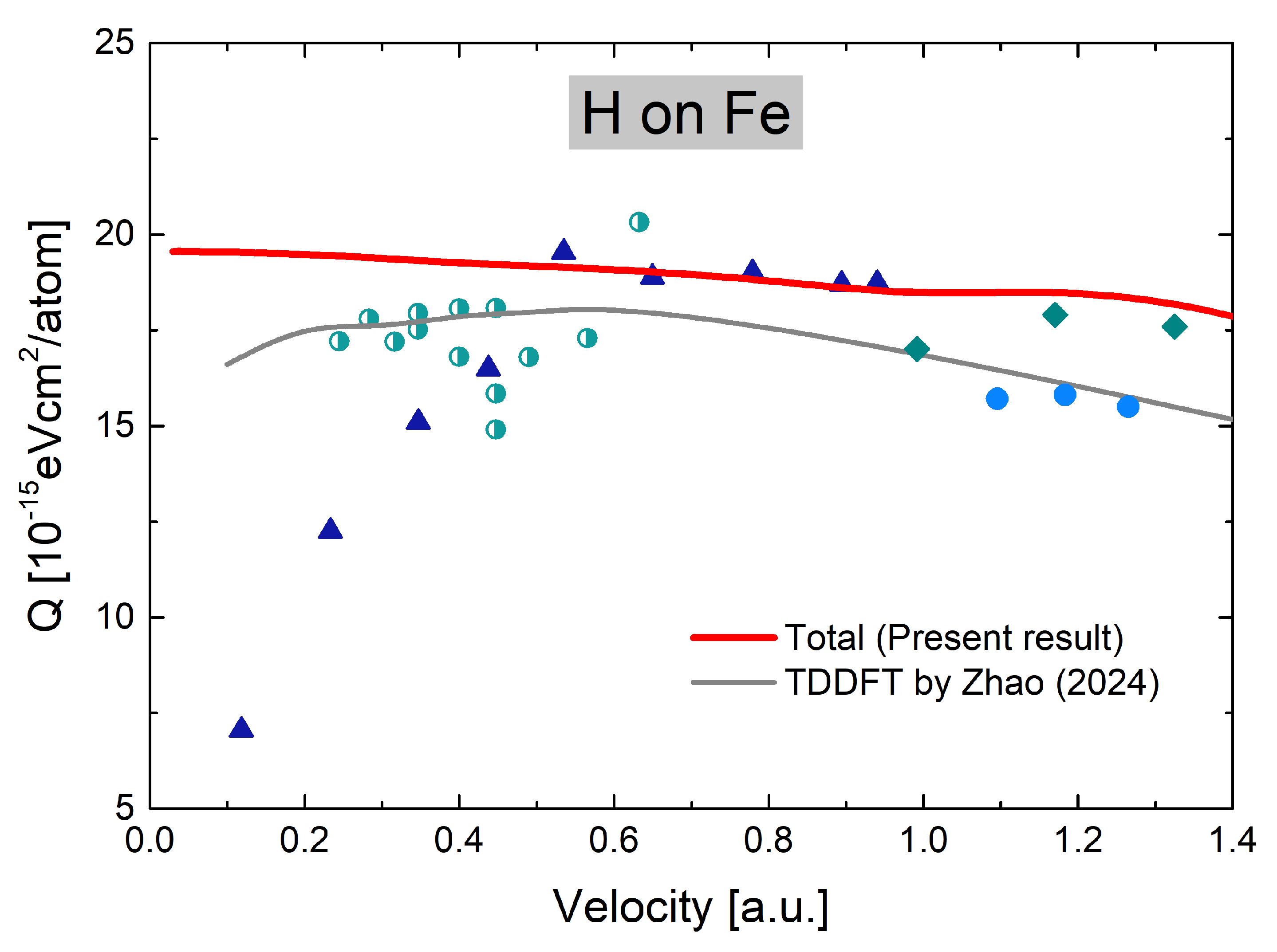
Figure 4.
Electronic stopping cross-section of Fe for H as a function of the impact energy. (a) Curves: present results for total stopping, red-solid line; d-electron contributions, red-dashed-dot line; FEG stopping, blue-dashed line; inner-shell contribution, orange-dotted line. Symbols: • [24], ▪ [46], ▾ [47], ▴ [42], ★ [48], ◂ [45], ▸ [49], ⧫ [22,23], ◦ [50]; and ◑ [33] for steel (eurofer97). (b) Curves: thick red-solid line, present total stopping; pink dashed-double-dot curve, MELF-GOS results by de Vera et al. [43]; thin gray-solid line, TDDFT results by Zhao et al. [11]; green-dashed curve srim [44]. Symbols as in figure (a).
Disclaimer/Publisher’s Note: The statements, opinions and data contained in all publications are solely those of the individual author(s) and contributor(s) and not of MDPI and/or the editor(s). MDPI and/or the editor(s) disclaim responsibility for any injury to people or property resulting from any ideas, methods, instructions or products referred to in the content. |
© 2024 by the authors. Licensee MDPI, Basel, Switzerland. This article is an open access article distributed under the terms and conditions of the Creative Commons Attribution (CC BY) license (https://creativecommons.org/licenses/by/4.0/).
Copyright: This open access article is published under a Creative Commons CC BY 4.0 license, which permit the free download, distribution, and reuse, provided that the author and preprint are cited in any reuse.


