
Submitted:
31 December 2024
Posted:
03 January 2025
You are already at the latest version
Abstract
Polymer electrolyte membrane (PEM) fuel cells are electrochemical devices that can transform the chemical energy stored in fuel directly into electrical energy, Commercialization of PEM fuel cells has progressed significantly in recent years. One of the primary obstacles preventing polymer electrolyte membrane fuel cells (PEMFCs) from being a commercially viable product is their durability. To offset insufficient fuel cell durability, it is critical to understand their degradation phenomena and study the degradation mechanisms of its components. This will allow novel component materials to be produced and novel viable designs to be achieved. The various causes of degradation in important cell components, such as membranes, gas diffusion layers, and catalyst layers were reviewed, which included accelerated stress test (AST) analysis. Thermodynamic and kinetic factors linked to fuel cell operation are discussed along with a discussion of reactions that may be involved in catalyst deterioration. The use of water collectors in PEMFCs mitigates the challenge of cathodic flooding in PEMFCs. Optimization of PEMFCs efficiency can also be achieved by introducing platinum, iron, and nickel deposition as support catalyst as well as by reduction in fuel cell ripples. Zirconated-based proton conducting materials show prospects as an alternative for Nafion due to its stability at high temperatures.
Keywords:
Polymer electrolyte membrane
; Fuel cells
; Catalyst layer
; Mechanical and chemical stability
; Nafion
; Proton conductivity
; Degradation
; Bipolar plates
; Diffusion
; Anode and cathode materials
1. Introduction
The need to combat climate change is the driving force behind scientists looking for greener forms of energy generation. One area that has been explored significantly in recent years is Fuel cell technologies. This is because fuel cells satisfy all the criteria for a long-term sustainable energy generation technology which includes efficiency in energy conversion, minimal gas emissions, high voltage, and potential for cogeneration [1]. The materials used in fabricating Fuel cells are environmentally friendly and can be manufactured without damage to the environment. Fuel cells are basically electrochemical devices that convert the chemical energy in fuel directly to electrical energy in a clean and efficient way [2]. Typically, fuel cells are classified based on the type of fuel used, the conditions for operations, the type of electrolyte, and the application for which they are designed [3]. Table 1 shows various types of fuel cells as well as their advantages and disadvantages.
Sharma et al. [4] categorized fuel cells based on the electrolyte membrane that they possess. These five categories of fuel cells are: Alkaline fuel cells (AFCs), Polymer electrolyte membrane fuel cells (PEMFCs), Molten carbonate fuel cells (MFCs), Solid oxide fuel cells (SOFCs) and Phosphoric acid fuel cells (PAFCs) [4]. Figure 1 shows the various fuels cells and their relationship in respect to operating temperatures, material cost, efficiency and fabrication cost.
2. Polymer Electrolyte Membrane Fuel Cells (PEMFCs)
Polymer Electrolyte Membrane (PEM) is a thin layer of polymer in the Fuel cell between the anode and the cathode that conducts protons from the anodic plate to the cathodic plate while preventing the transportation of electrons from the anode plate and oxygen from the cathodic plate. PEM fuel cells makes use of polymer electrolyte membrane in conducting protons as well as separation of the gaseous reactant at the anodic and cathodic chambers [7]. It typically has a thickness of about 10 -100μm and has a byproduct of water and heat [8]. PEMFCs usually requires quite expensive electrocatalyst in order to speed up electrochemical reactions at low temperatures. PEMFCs are notable for having high power densities, easy to scale up and operating at low a temperature. These features make them suitable in replacing internal combustion engines in vehicles [9]. Typically, PEMFCs operating in temperatures less than 80 oC have proven to have high power output [5]. However, one of the major challenges in the commercialization of PEMFCs is the storage and distribution of pure H2. Use of alcohol fuels in PEMFCs is often hampered by low catalytic activity at low temperatures [5]. On-board reformers have been proposed for hydrogen generation for PEMFCs, this approach also has the challenge of CO2 and CO generation. The produced CO has a strong the potential to poison the anode catalyst [10].
Figure 2.
A schematic of PEMFC [11].
Figure 2.
A schematic of PEMFC [11].
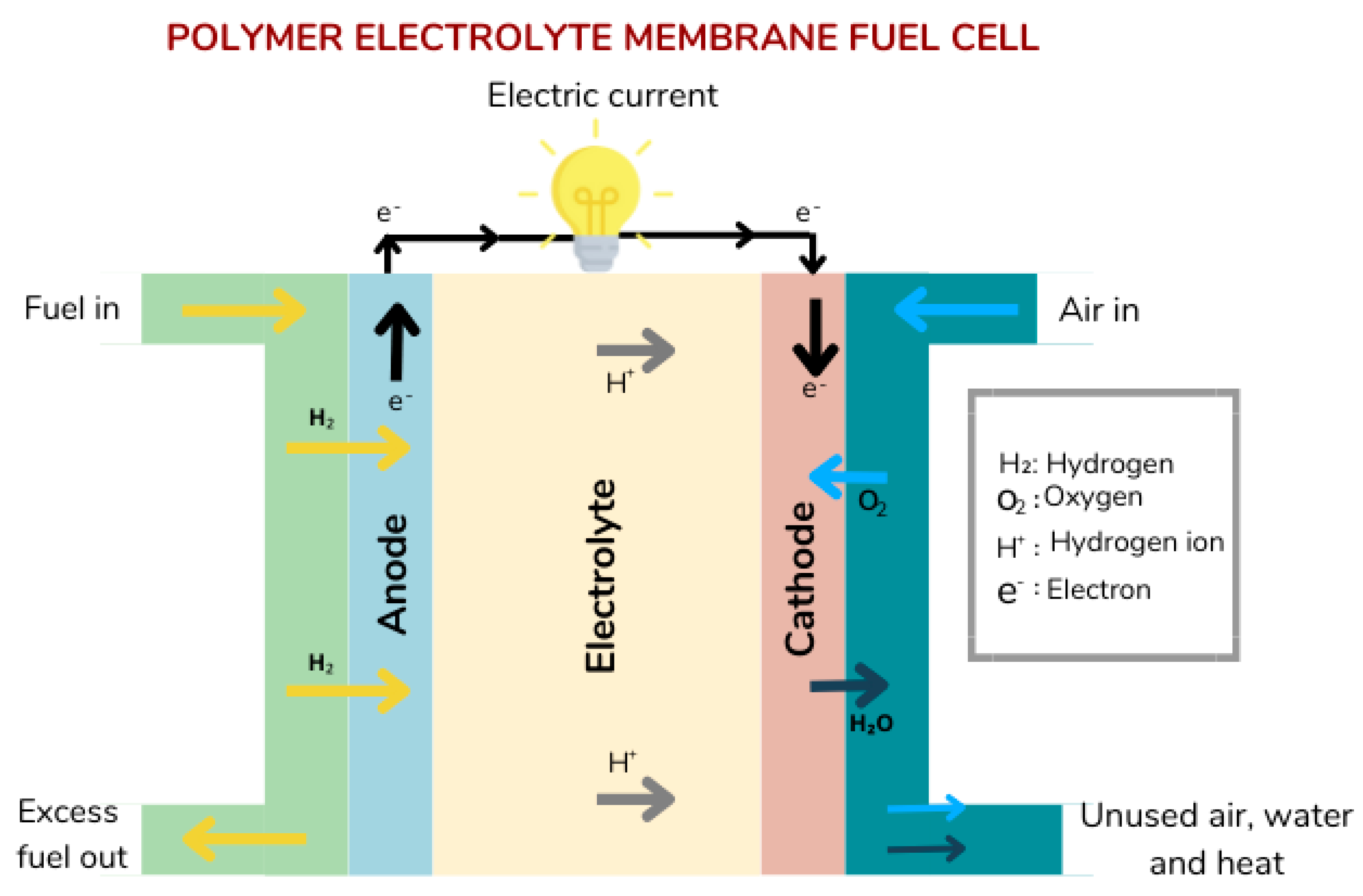
In comparison to other fuel cells, PEMFCs have gotten a lot of attention because of its good start-up characteristics, high power densities and high gravimetric/volumetric power density [12].
The PEM is situated between the catalyst layers of the anode and cathode. It has two primary functions which are: Separation of reactant gases of the anode and cathode as well as electrons, and the conduction of protons from the anode to the cathode catalyst layers. As a result of this, it is imperative that the PEM must be impermeable to gases and also insulated to electricity [13]. Furthermore, the membrane material must be chemically and mechanically stable to endure the conditions at with PEMFCs operates [14].
There are mathematical models that govern conservation of mass, momentum, species, charge energy and water transportation in PEMFC membrane [15].
Governing equation for conservation of mass [15]:
Where is the differential operator, is density, is the fluid velocity and is mass source that is added to the continuous phase.
Governing equation for conservation of Momentum [15]:
Where is pressure, represents force of gravitation on the body, is stress sensor and is the term representing the momentum source for porous media [15].
Governing equations for Stress sensor [15]:
Where is the unit tensor and is molecular viscosity. The volume dilation is given by the second term in the equation [15].
Governing equations for Species Transport [15]:
Where is effective diffusivity of species and is local mass fraction of species.
Governing equations for Electric Potential [15]:
Where is electric conductivity, S is a source term and represents electric potential.
Governing equations for Energy [15]:
Where is effective thermal conductivity and specific heat capacity. The energy transfer due to conduction is given by the first term of the equation.
Due to electrochemical reactions, the dissolved water content (λ) and volumetric source terms () for H2 and O2 in triple-phase boundaries (catalyst layers) is given as:
Where F is faraday’s constant and , are the molecular mass of water, oxygen and hydrogen.
PEMFC model for mass transfer and water transport can be described in the dissolved and liquid phases.
The dissolved phase equation is given as [15]:
Where is water content, is diffusion coefficient of water, is porosity of media, is ionic density, is water generation rate in catalyst layer resulting for cathodic reaction, is rate of change in mass between the dissolved and gas phases and is the rate of change in mass between the liquid and dissolved phases.
For liquid phase, the equation is given as [15]:
Where is density of liquid, is dynamic liquid viscosity, is abosulte permeabily and is relative permeability. is the rate of mass change between liquid and gas. The rate of transfer between liquid and gas phases can be obtained using calculations in unidirectional diffusion theory.
PEMFCs commonly use perfluorosulfonic acid (PFSA) as the PEM material. The primary chain resembles Teflon and is extremely hydrophobic. The sulfonic acid group, being a side chain end group, is very hydrophilic, allowing water adsorption for proton conduction. As a result, membrane hydration is critical and must be optimized to ensure that enough water is present for conduction of protons through it while preventing flooding of the catalyst and gas diffusion layers [16]. It is also important to note that the length of the side chain greatly influences the stability as well as the performance of the polymer electrolyte membrane [17].
There are two major types of PFSA membranes for application in PEMFCs and they are long side chain membranes and short side chain membranes. The main difference between both types are the side chain structural arrangement and the number of units of CF2 present [17].
PFSA membrane has some setbacks which includes the following: Due to conductivity of protons occurring at fully hydrated state of PEM, humidification od the reactant gases is inevitable and this complicates the system design as well as increase the cost of production. Shrinking and swelling resulting from cyclic changes of PEMFCs hydration can cause the structure to fail. Addition of fillers to mitigate this challenge leads to an increase in production cost. Its mechanical integrity can be compromised due to attack from cations in metals which causes decomposition of the polymer chain and this shut fall also affects its proton conductivity efficiency [30].
Catalyst layers: The catalyst layers (CLs) is the part of the fuel cell in which electrochemical reactions take place. The catalyst layer provides conduit for diverse species of reactants which include: proton transportation partway, conduit for electron transfer between the catalyst layer and the current collector and permeable pores for supply of reactants and removal of water. The material used in making a CL plays a major factor in the efficiency and durability of the fuel cell. The most common CL materials are made up of ionomers, electrocatalyst, void space and carbon support [17]. The fundamental motivation in the development of PEMFCs has been the optimization of process involved in preparation of CL ink. Catalyst layers generally made using catalyst ink dispersion which comprises of an ionomer, a dispersing solvent and a catalyst deposited on a support such as Pt/C [18]. It is also important to note that the properties of the catalyst and the microstructure’s heterogeneity on the structure play a significant role the quality of the catalyst layers. The nature of the dispersion medium, which governs ink properties such as aggregation size of the ionomer molecules, rate of solidification, its physical and mass transport properties and viscosity are critical components of catalyst layers that need further research. The approach in which the ink is deposited influences the choice of dispersion media. Screen printing and roll-to-roll coating, for example, necessitate viscous inks with high solids content (>5% wt%) and high additives with high boiling points, whereas spray coating necessitates lower solids content (2% wt%) and faster evaporating alcoholic- or water-based solvents [19]. According to Ott et al. [20], It is extremely desirable to reduce the Pt concentration in the cathode of proton exchange membrane fuel cells in order to reduce their costs. Lowering the Pt loading of the cathodic electrode, on the other hand, results in significant voltage losses. The mass transport resistance of O2 through the platinum–ionomer interface, the placement of the Pt particle with regard to the carbon support, and the structure of the supports are all known to cause voltage losses. Ott et al. [20] used N-modified ketjenblack carbon powder (N-KB) to develop a new Pt catalyst/support design that caused a reduction in local oxygen-related mass transport resistance significantly. The Columbic interaction between the ionomer and N groups on the carbon support ensures an astounding uniform coverage of the ionomer over the high surface-area carbon supports (N-KB 600°C), particularly under dry operating conditions, ensuring homogeneous ionomer distribution and replicability during the ink manufacturing process as depicted in Figure 1 [20].
The gradient distribution law of Pt loading, hydrophilicity/hydrophobicity and ionomers in the catalyst layer as well as the design and fabrication procedures of an ordered electrode based on a nanoarray structure was researched and discussed [21]. They insinuated that the GDL/CL interface gap causes liquid water to pool in the interfacial void space, reducing contact area. They emphasized on the necessity of a catalyst layer bulk structure and interlayer structure combination design technique. Li et al. [22] used accelerated stress test (AST) to simulate and investigate cathode catalyst layer (CCL) a startup-shutdown state, and an NDIR analyzer was used to capture real-time CO2 evolution. The rate of CO2 evolution during the AST confirmed the carbon corrosion behavior. The polarization and CV curves revealed a decline in electrochemical performance. It was also revealed that the performance drop caused by the increase in ohmic resistance was more pronounced at higher current densities than at lower current densities. Due to the production of passivating oxides on the carbon support, severe deterioration of CCL was seen during the first 5 k cycles, followed by a slower degradation thereafter. The reduction of CCL thickness and porosity, as seen in Figure 3 of [22], resulted in resulting in poor mass transmission and PEMFC performance reduction.
Alabi et al. [3] summarized the various types of catalyst and recent work done to improve their efficiencies.

Table 3.
Catalyst types, its advantages, disadvantages and research progress [3].
Table 3.
Catalyst types, its advantages, disadvantages and research progress [3].
| Catalyst Type | Advantage | Disadvantages | Recent Progress and Ongoing Research for Improvement |
|---|---|---|---|
| Platinum-based catalyst |
|
|
|
| Platinum free Catalyst |
|
|
|
| Alloy-Based electrocatalyst |
|
|
|
| Single atom catalyst |
|
|
|
| Metal free catalyst |
|
|
|
Gas Diffusion and Microporous layers: Between the bipolar plate (BP) and the CL of a PEMFC are gas diffusion layers (GDL) and microporous layers (MPL), collectively known as diffusion media (DM) [23]. The main functions of GDLs and MPLs is its provision of mechanical support for MEAs, a conduit supply of reactants, removal of products, and lastly an electron conduction conduit between CLs and Bipolar plates [24]. According to Niblett et al. [25], the water cluster configuration can be considerably influenced by the microstructure of the gas diffusion layer, with carbon paper reconstruction enabling water to diffuse mainly in the in-plane direction. This is connected to the percolation-controlled process, in which water branches to choose the path with the lowest entry capillary pressure. It’s important to note that both GDLs and MPLs are porous materials [26]. Previous studies have focused on microporous improvements, regulating hydrophobicity and internal water transport processes [27]. MPL/CL contact is one of the several interfaces between the fuel cell components that can induce losses ohms as well as mass transport [26].
Carbon paper is an option for production of GDLs on a commercial scale, carbon powder is also an option for MPLs [28]. To promote water drainage and reduce electrode flooding, carbon paper GDLs must be hydrophobic. For hydrophobicity treatment, polytetrafluoroethylene (PTFE) is frequently applied to carbon paper. The structure of carbon paper GDLs is anisotropic [29].
Polytetrafluoroethylene (PTFE) is normally concentrated at the surface of the GDL at low loading, and as the loading increases, it penetrates deeper into the GDL. Another observation is that the PTFE binder structure has changed, displaying a web-like porous shape rather as being smooth [8,29]. The GDL pores will be blocked by a large PTFE loading, which will impede mass movement [30]. The particle size distribution (PSD) is influenced by the PTFE loading, and the overall pore volume is reduced. No PSD change was found at a pore radius of ≤3µm, indicating that PTFE does not permeate pores in this size range. Pores with a diameter > 5µm were found to be the most affected, with a considerable reduction in volume as the PTFE loading increased from 5% to 20% [5]. As a result, the hydrophobicity and pore space of the GDL must be balanced for removal of liquids as well as the supply of gaseous reactant, accordingly. MPL is frequently used to improve the physical contact between the GDL and the CL. Its pore size is typically between that of GDLs and CLs, and it has been found to increase fuel cell efficiency in some cases due to better water management in the cathode [30]. Both GDLs and MPLs can benefit from machine learning and AI to improve their physical dimensions, pore sizes, permeabilities [2]. Niu et al. [32] carried out a three-dimensional numerical analysis of water removal in a lotus-like PEMFC flow channel to improve the drag reduction performance of the proton exchange membrane fuel cell. They concluded that microstructure shape parameters are capable of influencing effective water removal from the channel wall surface through the lotus-like channel.
Gas Flow Channel (GFC) and Bipolar plate (BP): Collection of Electricity, distribution of gaseous reactants, water and heat removals are all parts of the function of BPs. These functions are carried out through their installed GFC networks. In addition to these functions, BP materials must be resistant to corrosion in the FC environs [33]. Carbon composites and metals with adequate protective coatings, such as aluminum, titanium and stainless steel, have been investigated as viable BP materials in commercial PEM fuel cells [34]. Metal BPs provide a number of advantages, including minimized gas permeability, strong electric and thermal conductivities. In the acidic environment of fuel cells, resistance to corrosion is a serious issue. To protect metal substrates against corrosion, a suitable coating must be applied. Metallic nitrides, carbon, and composite coatings are common coating materials for aluminum [35]. A graphene-Ni layer, nitrides, and chromium carbide have all been examined as potential coating materials for stainless steels. Pure titanium has a stronger corrosion resistance than stainless steel, in a fuel cell environment, but there is the possibility that pure titanium may develop an oxide coating on its surface which can be a challenge [34]. In the development of metal BPs, mold surface defect prevention is a vital issue to address [36]. Zhu et al. [37] carried out an investigation of dynamic behavior if liquid water originating from GDL pores in gas flow channel of PEMFC using Volume of Fluid. They concluded that the interactions of a water droplet released onto the hydrophobic surface (GDL) of a fuel cell channel combined with air flow, results in a complicated process of droplet growth, distortion, wall attachment, breakage, recoil, and ultimately film creation. They also noted that in microchannels, the coalescence of two water droplets promotes deformation and water transportation and a decrease in pore width reduces the critical air velocity for the same starting droplet size.
Two Phase Flow: Two-phase flow, which is caused by the oxygen reduction reaction (ORR) producing water, is a common occurrence in PEMFCs, with the two phases referring reactant gasses as well as liquid water [38]. Excess liquid water will obstruct the supply of reactants to the reaction sites, thereby increasing concentration polarization. Two-phase flow, which is caused by the ORR producing water, is a common occurrence in PEMFCs, with the two phases referring reactant gasses as well as liquid water. Excess liquid water will obstruct the supply of reactants to the reaction sites, thereby increasing concentration polarization. his leads to local reactant starvation, material degradation, decrease in efficiency, and operation stability, and local reactant starvation that induces material degradation [40]. The flow of water is through porous components of PEMFCs is primarily driven by capillary pressure (Pc), which can be defined the difference in pressure between the liquid and gas phases [6].
The pressure difference between the liquid and gas phases is defined as: The Leverett J-function, which represents the Pc correlation as a function of liquid saturation(s) as well as parameters such as Pg (gas phase pressure), Pl (pressure of liquid phase), surface tension (σ), porosity (θc), contact angle (θc), and permeability (K) [6].
Where σ represents surface tension [6].
One other important mechanism for liquid water transport is vapor-phase diffusion and phase change. The driving mechanism for liquid water transport temperature gradients and is known as the heat pipe effect. The diffusive flux for vapor is expressed a [6]s
Where Cw is water concentration, T is temperature, P is pressure, is effective diffusivity coefficient for water vapor.
This flux can be as high as 40% of the ORR's water output rate in a fuel cell [40]. PEM fuel cells need to be developed further not only in terms of cost, but also in terms of durability. The voltage loss per hour under a fixed current, which is directly related to fuel cell material degradation, is commonly used to determine durability [41]. Electrochemical/chemical degradation is primarily caused by catalyst dissolution or ripening, carbon oxidation, and radical or ionic species assault; mechanical degradation is caused by cyclic compression, material expansion, or membrane crack formation [42]. The loss of electrochemically active surface area (ECSA) is a standard metric for assessing electrocatalyst activity deterioration due to catalytic ripening/instability and carbon support corrosion [43]. Xing et al. [5] investigations on two phase flow patterns in gas channels, their investigations revealed that two-phase flow is found to be characterized by semi-slug or slugs at low surface air velocities which leads to substantial variations in pressure drop. While at higher air velocities, hydrophilic channel walls form a water film.
Durability: PEM fuel cells must be developed further not only in terms of cost, but also in terms of durability. Monitoring the rate of degradation is used in assessing the durability of Fuel cells. Degradation is commonly linked to the, mechanical, chemical, electrochemical stabilities of the various components, with emphasis on membrane electrode assembly (MEA) [44]. Degradation with respect to electrochemical and chemical activities is caused by carbon oxidation, ionic species assault, catalyst dissolution while mechanical degradation is caused by effects of mechanical stress and strain on fuel cell membranes [45]. Because PEMFC breakdown occurs over a long period of time, doing experimental research is quite expensive. The main causes of membranes losing structural integrity are cyclic hydration/dehydration and fuel cell compression over time [46]. Crossover of reactant gasses occurs when pinholes are formed which is often a result of the swelling and shrinking of cyclic membrane [47]. Chemical stress can diminish proton conductivity and membrane thickness, allowing reactant gas crossover. Attacking species that destroy the membrane structure are frequently responsible for chemical degradation [27]. Carboxylic acid as well as other end groups containing hydrogen can form as result of a chemical reaction or membrane polymerization, they are usually prone to assault [48,49]. As a result, free radical attack on reactive end groups might lead to degradation. Membrane unzipping/conductivity loss occurs as a result of these attacks [50]. Furthermore, because the sulfonic sites have a higher affinity for foreign cations than H+, the presence of cation impurities may impair proton conductivity [51]. The principal failure mode for fuel cell designs is thought to be the degradation of carbon supported platinum cathode catalysts [41]. Particle sintering of platinum, dissolution of platinum, and carbon support corrosion have all been hypothesized as mechanisms that contribute to cathode catalyst degradation [52]. Dissolution of Pt according to Yu et al. [28], is minimal when the potential is low or high but very significant at intermediate potentials. Ikuma and Shyam [53] investigations of durability of PEMPC catalyst in liquid electrolytes using a voltage cyclic procedure showed that Pt's durability in sulfuric acid is to be lower than in perchloric acid, i.e., Pt is more easily dissolved when sulfate ions are present. Durability was shown to increase in the order as follows: H2SO4 > H3PO4 > HClO4.
PEMFC catalyst layers polyelectrolyte: Although the amount of polyelectrolyte used in catalyst layers is less than that used in membranes, it is nevertheless significant because it is influences performances of electrode, platinum consumption, as well as MEA durability [54]. Nafion ionomers are used as a binder [51]. They are also employed in proton conducting electrolyte in to broaden boundary formation of electrochemical triple-phase. This is crucial for achieving a good Pt usage which results in a high MEA performance [55]. The movement of electrons, protons as well as reactants in a catalyst layer is depicted in Figure 4.
It can be observed from Figure 4 that the reactants must move through the electrolyte (which conducts protons) so as to arrive at the reaction site where it participates in reactions at the electrode [50]. It is imperative that catalyst layer electrolyte is permeable for reactants so as to ensure there is no impedance in reactant transport [56]. The polyelectrolyte employed in membranes require little or no reactant permeability which shows it completely different from that used in catalyst layer [57].
Another challenge encountered is the formation of water at the electrodes, which comprises of mostly aromatic hydrocarbon which are more hydrophilic in comparison to Nafion [58]. Water formed at the electrode inhibits the transportation of reactants such as oxidant and fuel [59].
Oxygen reduction to water occurs at the cathodic catalyst layer through an electrochemical reduction process [60]. H2O2 is also formed as a byproduct in the reaction. This has been proven on Pt catalyst (Pt/C) [61]. The production of H2O2 increases as the agglomerations of Pt/C decreases [61]. Even while there is still a debate over the production sites of H2O2 and how exactly the mechanism behind H2O2 attacks of polyelectrolyte works, it is generally understood that H2O2 is destructive to catalyst layers and negatively impacts on its durability [61]. While membrane polyelectrolyte is located a little farther from ORR reaction sites, catalyst layer polyelectrolyte is directly in contact with ORR reaction sites and H2O2 concentrations is usually higher compared to membrane [63].
Due to the challenges presented by H2O2 formation. Catalyst layer polyelectrolyte must be more stable chemically as opposed to the polyelectrolyte of membrane [64]. Chemical stability evaluation is done using the Fenton’s reagent test [65], which involves immersing the polymer in heated 3% H2O2/1ppm Fe (II) solution to assess its chemical stability. It is also used to screen potential polymer membrane substitute technologies [66].
Protons in PEMFC usually transport in a vertical trajectory to the surface plane of the membrane [67]. Anisotropic transportation of protons, where the protons conductivity along the membrane’s plane is stronger is advantageous for polymer membrane [68]. However, this is not the same for catalyst layer, where proton movement is more asymmetric [69]. The dimensional and mechanical stability of polymer membranes is extremely important [70], this might not be the case for catalyst layer polyelectrolyte. In a nut shell, the polyelectrolyte needed for PEMFCs catalyst layers and membrane are vastly different [76]. As a result, it may be concluded that different polyelectrolytes should be used or recommended depending on its catalyst layer or embrace for PEMFCs [71]. Owning to the nonadsorbing behavior of the sulfonic acid anions on the surface of Pt catalyst, it is observed that metal catalyst for reduction of oxygen is higher in Nafion electrolytes [72]. The rates of oxygen reduction in the Nafion system are also faster compared to other polymers having a sulfonic acid group [72]. Mitigation of H2O2 formation is greatly influenced by fluorination of Nafion backbone [74]. Nafion also a high level of chemical stability in a Fenton’s reagent test [75]. The high cost of Nafion impacts on the overall PEMFCs cost [76]. Hence, Nafion is considered as a next generation polyelectrolyte choice for catalyst layer. Nafions do not perform well as a membrane electrolyte [76]. Researches are been carried out to find alternative polymer electrolyte for membranes [77].
3. Discussions
Flooding in PEMFC and Efficiency of Fuel Cell
One of the most important factors for the effective and stable operation of proton exchange membrane fuel cells is water management (PEMFCs) [78]. At high operation current densities, water flooding is a common occurrence, particularly downstream of the flow channel where the produced water should discharge [79]. Achieving proper membrane hydration and preventing flooding in the catalyst and gas diffusion layers should be the goals of effective water management. Flooding will result in safety concerns due to of the cell reversal, in addition to performance resulting from the restricted reactant supply [80]. Multi-phase models were created to explore liquid/gas transport in porous GDL and flow channels in recent years as liquid water transport emerged as one of the main challenges in fuel cell modeling [81].
There are three potential sources of water transport in the cathode of a PEMFC: the reactant gases (oxygen), electrochemical reaction at the catalyst layer, and net water transport through the membrane [82]. Protons traveling through the electrolyte under the impact of electro-osmotic drag cause water to move from the anode to the cathode during operation [82]. Water concentration on the cathodic section is generally higher than that of the anodic section because water is created in the electrochemical reaction at the cathode [84]. The increased in gradient of water concentration in the membrane causes a back diffusion of water from cathode to anode to occur [85]. The early models assumed that water was in a gaseous state, which is not true for operations involving high current densities or significant humidification [86]. There have been some indications of flooding in the catalytic layer. No experimental evidence supported the assumption that the liquid and gas phases were continuous in these two-phase flow models [87].
Most of the current models fall under the continuum method, where average porous media properties like porosity, pore diameter and permeability have been used in the assumed homogenous diffusion layer [26]. Wang et al. [87] classified two-phase flow and transport modeling into two distinct approaches: pore-scale method and continuum method. However, the diffusivity of liquid water and gas varies significantly for various pore characterizations. Understanding of the transport processes in fuel cells may be improved by using the pore-scale technique for liquid transport modeling. The performance of PEMFCs is directly impacted by the challenging and significant problem of water management [88]. A lack of water would cause the membrane to hydrate, which would lower proton conductivity [88]. In the meantime, too much water would cause flooding in the catalyst layer, the gas diffusion layer, and even the flow channel, impeding the transport of the reactants [54]. There are numerous initiatives to enhance water management in PEMFC, including bipolar plate improvements, porous media of the catalyst layer or gas diffusion layer, and the control system [89]. The main problem with water management in the operation process is striking a balance between dehydration and flooding. Flooding may cause PEMFC performance, safe operation, and longevity to suffer [56]. Numerous academic works have documented the presence of flooding in PEMFCs. Soft X-ray radiography was created by Sasabe et al. [89] to view the movement of liquid water inside a PEMFC. The findings revealed that the area under the ribs had more liquid water than the area beneath the channels. In a transparent PEMFC, liquid water was examined by Zhan et al. [91] using a high-speed camera. They discovered that if the velocity of the gas wasn't sufficient, the liquid water would stick to the channel walls.
Fuel cells generate both heat and current. A fuel cell's thermal and water management is the consequence of a number of coupled processes, which includes the flow of gas and fluid as well as mass/heat transfer, that happens inside the fuel cell [92]. Severe mass transportation limits may result from inadequate thermal and water management. The PEM fuel cell cathode is the limiting component of a PEM and this is because of the slower oxygen reduction kinetics and mass transfer contains imposed by liquid water that is both produced by the electrochemical reaction and carried to the cathode by the electro-osmotic drag [93].
Nafion
Nafion is generally regarded as a benchmark polymer, hence any novel materials must be evaluated against it [109]. Corti et al. [110] used differential scanning calorimetry (DSC), to investigate the low temperature thermal behavior of Nafion 117 membranes with various water contents and equilibrated with water-methanol mixtures of various concentrations was investigated (DSC). They observed that DSC analysis of the low-temperature transition of nafion thermal relaxation was consistent with previous knowledge of mechanical relaxations. Also, a glass transition was the reason for the thermal transition that was seen in the dry Nafion (acid form) samples at -108 °C. when the relative humidity to which the samples were subjected was increased, there was a minor plasticizing effect of water on the Nafion membrane, although it is not as significant as that seen with biopolymers and the thermal transition shifted to a lower temperature. Lastly, methanol presence increased the amount of freezable water, which was most likely due to the due to the supercooling of methanol after cooling, that might have led to the replacement of water with methanol in the solvation of ionic groups on the matrix. Chugh et al. [111] examined 30 cells of low-temperature PEM fuel stack using Nafion®-212 membranes using MATLAB. The study concluded that an increase in temperature from 500C to 800C caused a corresponding increase in stack voltage by 25%, this was because the ohmic resistance and activation potential was considerably lower. However, any increase in the operating temperature beyond 800C resulted in membrane degradation and hydration. Okonkwo et al. [61] suggested that at low temperatures for Fuel cells, the main mechanisms for chemical degradations of Nafion are main chain unzipping and side-chain scissions.
High Temperature PEMFCs
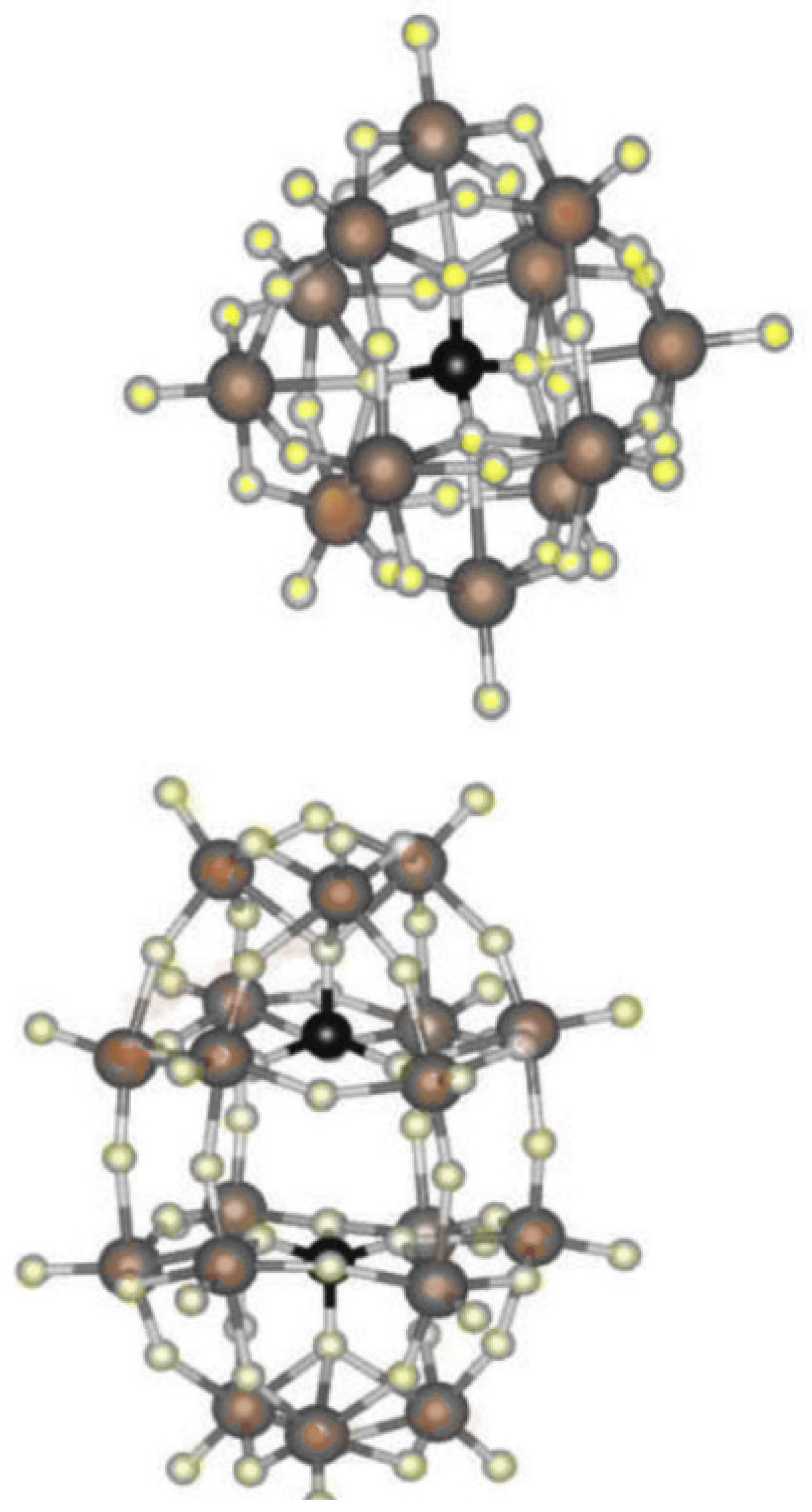
High temperature proton exchange membrane fuel (HT-PEMFC) cells operate above 100oC and as such have a wide range of applications due to their compatibility to environments and high efficiency [114]. Due to their high tolerance level to poisoning from feed gases, HT-PEMFCs have a competitive advantage over conventional PEMFCs [116]. HT-PEMFCs do not require water management systems as they do not accumulate water at high temperatures. However, there are several challenges such as lack of models in comparison to conventional PEMFCs [115]. It is also noteworthy to state that properties and behaviors of fuel cells in in-situ environments that cannot be measured may differ significantly from measured ex-situ properties carried out in ideal environment [115]. The use of heteropolyacid (HPA) as an additive to improve PEMFCs and make them suitable for high temperature conditions is an area receiving lots of focus in present day research [123]. The thermal stability and ability of HPAs such as phosphomolybdic acid (PMA), silicotungstic acid (SWA), phosphotungstic acid (PWA), etc, to form a variety of different structures through the additions of other elements, makes them suitable for membrane application in high-temperature environment [117]. HPA can be employed as stand-alone catalyst, can be used as catalyst boosters, and can be applied in improving ionic conductivity in membranes [117]. HPAs can be effectively used as catalyst or acid depending on their structure.
Figure 5.
A diagram depicting HPA variations of structure: yellow balls are oxygen atoms; brown balls are addenda atoms and black balls are phosphorus atoms [117].
Figure 5.
A diagram depicting HPA variations of structure: yellow balls are oxygen atoms; brown balls are addenda atoms and black balls are phosphorus atoms [117].
4. Recommendation
Flooding in PEMFC
In order to maintain strong ionic conductivity, keep the membrane completely hydrated, and improve PEMFC performance, efficient water management is required. By blocking the pores in the gas diffusion layer and covering active sites in the catalyst layer, liquid water can stop reactant species from moving [94]. Natarajan and Nguyen [95] developed a 3-D model to take into consideration the variations in the oxygen level along the channel and its importance for the current density. The magnetic particles would raise the limited current of the fuel cell by providing greater space for oxygen gas, as stated by Wang et al. [96]. When magnetic particles were added to the catalyst layer of a cathode to magnetized states, the cell's efficiency increased compared to non-magnetized states.
Newman and Fuller [97] developed a model for heat and water management. The model included dimensions encompassing the channel and reactive interface. But they did not include the diffusion layer. Dutta et al. [98] created a complete three-dimensional model that included the electrode width, a dimension parallel to the reactive surface. They included the whole fuel cell in their model, with the cathode and anode sides' conventional gas distributors accounted for. But the water management model did not include liquid water from the gas diffusion layer. For the cathode side of PEM fuel cells, Jamekhorshid et al. [97] proposed two-dimensional pore-scale and volume-effective approaches based on electrochemical equations and conservation laws. Two-dimensional pore-scale and volume-effective approaches are proposed for the cathode side of PEM fuel cells, based on electrochemical equations and conservation laws. The results of this model show a clear correlation between increasing average current density and cathode inlet humidity, but the system also becomes more susceptible to flooding. The relative humidity at the anode inlet exhibits a comparable effect. Additionally, they noticed that running the cell at a higher temperature will lead to higher average current densities, which lessens the chance of the system overflowing. Higher cathode stoichiometries inhibits flooding of the system [99]. A higher anode stoichiometry leads to a higher average current density and increased sensitivity to cathode flooding [89]. A cathode catalyst layer was created by Li et al. [53] for water management. They achieved this by enhancing the water balance and oxygen transport in the cathode by adding hydrophobic dimethyl silicone oil and oxygen (DSO) to a catalyst layer. The results showed that PEMFCs using DSO cathodes outperformed those using regular cathodes. The greatest power density of a PEMFC with a DSO-containing cathode was 356 mWcm-2, compared to 144 mWcm-2 for a conventional cathode. The results of their experiment suggested that the enhanced hydrophobicity of the cathode catalyst layer, which aids in the removal of water from catalyst layer gaps, may be responsible for the notable improvement in fuel cell efficiency with the DSO loaded cathode. In a study, Santarelli et al. [100] examined the effects of air cathode stoichiometry on the amount of power produced in a PEMFC stack. They came to the following conclusions: (1) the air stoichiometry has an increasingly obvious effect at high current; (2) the heat generated by irreversibility raises the cathode flow outlet temperature, which improves water transportation; and (3) air stoichiometry below 2 should be avoided. Fabian et al [101], studies on passive water management at the cathode using galvanostatic measurements showed that flooding in an air-breathing cathode can result in either significant flooding or a partially flooded surface, which could affect the cell potential and the corresponding fuel cell energy conversion efficiency. They installed a water collector, which conducts electricity between the cathode surface and the current collector, to help resolve this issue. The water collector was found to prevent cathode flooding by dispersing and absorbing water throughout the cathode.
PEMFC Efficiency
Seo and Lee [105] investigated the effects of variation in operating conditions on the phenomenon of methanol crossover and the efficiency of Direct methanol fuel cell. Electric power and nitrogen gas were used to test the methanol crossover current. They concluded that raising the operating temperature enhanced the fuel cell's performance by promoting active electrochemical processes. On the other hand, there were drawbacks such as significant concentration loss and electro-osmotic drag within the system. The fuel cell's stack steady-state efficiency was examined by Hou et al. [106]. In order to simulate the fuel cell stack's acceleration signals and depict the load spectra, they conducted the experiment. The acceleration indications were represented by means of car vibration test results from the past. They concluded that the fuel cell stack's steady-state performance is significantly impacted by the enhanced road vibration and that this should not be overlooked while doing research. On the other hand, there were drawbacks such as significant concentration loss and electro-osmotic drag within the system. The fuel cell's stack steady-state efficiency was examined by Hou et al. [106]. In order to simulate the fuel cell stack's acceleration signals and depict the load spectra, they conducted the experiment. The acceleration indications were represented by means of car vibration test results from the past. They concluded that the fuel cell stack's steady-state performance is significantly impacted by the enhanced road vibration and that this should not be overlooked while doing research. Modeling the fuel cell system, Zhao and Burke [107] studied operating conditions in an effort to improve the system by changing the back pressure. In contrast to fixed back pressure operation, they found that fuel cell systems with optimal changing back pressure operation are able to maximize net system power and achieve superior system efficiency over the complete operating range. A novel design for a two-phase interleaved DC/DC boost converter-based proton exchange membrane fuel cell (PEMFC) was developed by Cao et al. [102]. The study's objective was to lessen fuel cell ripples in order to increase PEMFC longevity. The output voltage terminal was raised by a two-phase interleaved boost DC/DC converter. In addition, they suggested a more effective algorithm for selecting the ideal linear quadratic regulator coefficient, which was in line with an enhanced system.
Litkohi et al. [108] looked at the effects of adding catalytic composition of nickel, iron, and platinum deposition as an electrocatalyst on functionalized carbon nanotubes (FCNTs). They found that by utilizing the four-electron pathway, the oxygen reduction process (ORR) was accelerated when FCNTs were used as the support catalyst in combination with hybrid platinum and transition metals. This was caused by the alloys of CNTs and Pt-transition metal that had high crystallinity, low defect density, and unique electrical conductivity. They concluded that Pt-Fe-Ni/CNT electrocatalyst loaded on Teflonized carbon cloth is a promising combination for the catalyst layer in polymer fuel cells in the future.
Nafion
A key problem with Nafion is its low mechanical instability at high temperatures [112], which is why attention is now being drawn to zirconate-based materials as a possible substitute [113]. Materials based on zirconate have good proton conductivity and stability over a broad temperature range. Their distinctive properties, including low thermal conductivity, low thermal expansion coefficient, and low dielectric loss, have led to their current employment in the creation of hydrogen censors [113]. These properties can be taken advantage of in PEMFCs to overcome challenges associated with operating at high temperature. But in order to use zirconated materials for PEMFC applications, problems like instability in a CO2 and water vapor generation must be resolved. It is necessary to address issues with overpotential, material selection, doping concentrations, and temperature dependence of performance [113].
High Temperature PEMFCs
Polybenzimidazole (PBI) has been studied extensively in PEMFC applications due to its stability under high temperature conditions and commercial availability [123]. Studies conducted over the past two decades have demonstrated outstanding thermo-chemical stability and excellent conductivity when phosphoric acid is used as a dopant in PBI membranes [124]. For high temperature PEMFC, membranes composed of PWA/PBI or SWA/PBI doped with phosphoric acid showed superior conductivity to virgin PBI membranes [118]. Nguyen et al. [119] state that doping PBI membranes with phosphoric acid above 1200C in a low-humidity environment results in high conductivity and mechanical stability of the materials. Zhai et al. [120] used a series of intermittent life tests (100h, 300h, and 520h) for the phosphoric acid doped PBI (H3PO4/PBI) membrane of a single proton membrane fuel cell to study the stability of Pt/C electrocatalyst. They concluded that the loss of the PT/C cathode electrocatalyst's electrochemical surface area caused a considerable degradation of the H3PO4/PBI high temperature PEMFC over its life test. Park et al.'s research [121] on the function of binders in PEMFC electrodes at high temperatures concluded that the lifespan and performance of the fuel cell were influenced by the binder characteristics in the catalytic layers of electrodes at high temperatures. They demonstrated that simply changing the binders from polytetrafluoroethylene to polyurethane may cause the voltage of the cell to vary from 0.583 to 0.619V at 0.3A/cm2. Wang et al.'s study [122] examined the impact of varying cooling surface temperatures on the efficiency of high-temperature PEMFCs through the use of a 3D computational fluid dynamics (CFD) simulation. Their findings demonstrated that the PEMFC's peak power density and current density decreased as the cooling surface temperature differential increased. The peak power density decreased by roughly 9.14% as the temperature differential grew from 0K to 40K. Furthermore, they demonstrated that, in contrast to GDL, CL, and BPs, the phosphoric acid-dope PBI membrane had the largest stresses during the operation. Compressive stress accounted for most of these stresses. Within a temperature range of 0 to 40K, the minimum compressive stress ranged from 36.259MPa to 40.927MPa, while the maximum stress ranged from 29.944MPa to 38.964MPa
5. Conclusions
The longevity, reliability, cost and performance of PEMFCs determine whether fuel cell technologies will be successful or not. Several improvements such as a simpler BP design, control of produced water, increased fuel tolerance for contaminants, better heat utilization and improved stability of components has been achieved. There is still a lot of research being done to identify materials with a lower cost and greater endurance, as well as enhancement in electrochemical reactions created with various appropriate materials. Improvement of catalyst properties will slow down degradation and improve the overall properties of PEMFCs. It is still being actively researched how to modify polymer structures and different material types and compositions to produce stable and dependable products. Designing systems that functions to deliver power production at optimum efficiency while maintaining longer life spans of the components needs to be briefly focused on to avoid rapid degradation of PEMFCs. Use of Zirconate materials as an alternative for Nafion is an area that needs to be explored. The potentials of doped PBI for PEMFCs membranes under high temperature has shown to be viable and if optimized can be exploited in commercializing PEMFCs for high temperature environments.
Conflicts of Interest
The authors declared no potential conflicts of interest with respect to the research, authorship, and/or publication of this article.
References
- Kordesch, K.V.; Simader, G.R. Environmental Impact of Fuel Cell Technology. Chem. Rev. 1995, 95, 191–207. [Google Scholar] [CrossRef]
- Wang, Y.; Diaz, D.F.R.; Chen, K.S.; Wang, Z.; Adroher, X.C. Materials, technological status, and fundamentals of PEM fuel cells—A review. Mater. Today 2020, 32, 178–203. [Google Scholar] [CrossRef]
- Alabi, A.S.; Popoola, A.P.I.; Popoola, O.M.; Mathe, N.R.; Abdulwahab, M. Materials for electrocatalysts in proton exchange membrane fuel cell: A brief review. Front. Energy Res. 2023, 11, 1091105. [Google Scholar] [CrossRef]
- Sharma, D.K.; Filipponi, M.; Di Schino, A.; Rossi, F.; Castaldi, J. Corrosion behaviour of high temperature fuel cells: Issues for materials selection. Metalurgija 2019, 58, 347–351. [Google Scholar]
- Zhang, J.; Aili, D.; Lu, S.; Li, Q.; Jiang, S.P. Advancement toward Polymer Electrolyte Membrane Fuel Cells at Elevated Temperatures. Research 2020, 2020, 9089405. [Google Scholar] [CrossRef] [PubMed]
- Wang, Y.; Seo, B.; Wang, B.; Zamel, N.; Jiao, K.; Adroher, X.C. Fundamentals, materials, and machine learning of polymer electrolyte membrane fuel cell technology. Energy AI 2020, 1, 100014. [Google Scholar] [CrossRef]
- Wang, J.; Zhou, X.; Li, B.; Yang, D.; Lv, H.; Xiao, Q.; Ming, P.; Wei, X.; Zhang, C. Highly efficient, cell reversal resistant PEMFC based on PtNi/C octahedral and OER composite catalyst. Int. J. Hydrogen Energy 2020, 45, 8930–8940. [Google Scholar] [CrossRef]
- Wang, Y.; Chen, K.S.; Mishler, J.; Cho, S.C.; Adroher, X.C. A review of polymer electrolyte membrane fuel cells: Technology, applications, and needs on fundamental research. Appl. Energy 2011, 88, 981–1007. [Google Scholar] [CrossRef]
- Staffell, I. Zero carbon infinite COP heat from fuel cell CHP. Appl. Energy 2015, 147, 373–385. [Google Scholar] [CrossRef]
- energy ID-I journal of hydrogen, 2002. Technical, environmental and exergetic aspects of hydrogen energy systems. Elsevier n.d.
- Wang, Y.; Chen, K.S.; Mishler, J.; Cho, S.C.; Adroher, X.C. A review of polymer electrolyte membrane fuel cells: Technology, applications, and needs on fundamental research. Appl. Energy 2011, 88, 981–1007. [Google Scholar] [CrossRef]
- Sundmacher, K. Fuel Cell Engineering: Toward the Design of Efficient Electrochemical Power Plants. Ind. Eng. Chem. Res. 2010, 49, 10159–10182. [Google Scholar] [CrossRef]
- Najafi, B.; Mamaghani, A.H.; Rinaldi, F.; Casalegno, A. Fuel partialization and power/heat shifting strategies applied to a 30 kW el high temperature PEM fuel cell based residential micro cogeneration plant. Int. J. Hydrogen Energy 2015, 40, 14224–14234. [Google Scholar] [CrossRef]
- Chandan, A.; Hattenberger, M.; El-Kharouf, A.; Du, S.; Dhir, A.; Self, V.; Pollet, B.G.; Ingram, A.; Bujalski, W. High temperature (HT) polymer electrolyte membrane fuel cells (PEMFC)—A review. J. Power Sources 2013, 231, 264–278. [Google Scholar] [CrossRef]
- Vuppala, R.K.S.S.; Chaedir, B.A.; Jiang, L.; Chen, L.; Aziz, M.; Sasmito, A.P. Optimization of Membrane Electrode Assembly of PEM Fuel Cell by Response Surface Method. Molecules 2019, 24, 3097. [Google Scholar] [CrossRef] [PubMed]
- Dupuis, A.C. Proton exchange membranes for fuel cells operated at medium temperatures: Materials and experimental techniques. Prog. Mater. Sci. 2011, 56, 289–327. [Google Scholar] [CrossRef]
- Talukdar, K.; Gazdzicki, P.; Friedrich, K.A. Comparative investigation into the performance and durability of long and short side chain ionomers in Polymer Electrolyte Membrane Fuel Cells. J. Power Sources 2019, 439, 227078. [Google Scholar] [CrossRef]
- Bapat, S.; Giehl, C.; Kohsakowski, S.; Peinecke, V.; Schäffler, M.; Segets, D. On the state and stability of fuel cell catalyst inks. Adv. Powder Technol. 2021, 32, 3845–3859. [Google Scholar] [CrossRef]
- Cantillo, N.M.; Zawodzinski, T.A. Effect of Carbon Structure and Ink Composition on 3M Ionomer Adsorption. ECS Meet. Abstr. 2020, MA2020-01, 1649. [Google Scholar] [CrossRef]
- Ott, S.; Orfanidi, A.; Schmies, H.; Anke, B.; Nong, H.N.; Hübner, J.; Gernert, U.; Gliech, M.; Lerch, M.; Strasser, P. Ionomer distribution control in porous carbon-supported catalyst layers for high-power and low Pt-loaded proton exchange membrane fuel cells. Nat. Mater. 2019, 19, 77–85. [Google Scholar] [CrossRef] [PubMed]
- Chen, M.; Zhao, C.; Sun, F.; Fan, J.; Li, H.; Wang, H. Research progress of catalyst layer and interlayer interface structures in membrane electrode assembly (MEA) for proton exchange membrane fuel cell (PEMFC) system. eTransportation 2020, 5, 100075. [Google Scholar] [CrossRef]
- Li, Y.; Zheng, Z.; Chen, X.; Liu, Y.; Liu, M.; Li, J.; Xiong, D.; Xu, J. Carbon corrosion behaviors and the mechanical properties of proton exchange membrane fuel cell cathode catalyst layer. Int. J. Hydrogen Energy 2020, 45, 23519–23525. [Google Scholar] [CrossRef]
- Mukherjee, M. Characterization of gas transport phenomena in gas diffusion layers in a membrane fuel cell. 2020.
- Wang, Y.; Diaz, D.F.; Chen, K.S.; Wang, Z.; Adroher, X.C. Materials, technological status, and fundamentals of PEM fuel cells–a review. Mater. Today 2020, 32, 178–203. [Google Scholar] [CrossRef]
- Niblett, D.; Mularczyk, A.; Niasar, V.; Eller, J.; Holmes, S. Two-phase flow dynamics in a gas diffusion layer - gas channel - microporous layer system. J. Power Sources 2020, 471, 228427. [Google Scholar] [CrossRef]
- Pant, L.M.; Mitra, S.K.; Secanell, M. Absolute permeability and Knudsen diffusivity measurements in PEMFC gas diffusion layers and micro porous layers. J. Power Sources 2012, 206, 153–160. [Google Scholar] [CrossRef]
- Collier, A.; Wang, H.; Yuan, X.Z.; Zhang, J.; Wilkinson, D.P. Degradation of polymer electrolyte membranes. Int. J. Hydrogen Energy 2006, 31, 1838–1854. [Google Scholar] [CrossRef]
- Yu, J.; Yoshikawa, Y.; Matsuura, T.; Islam, N.; Hori, M. Preparing Gas-Diffusion Layers of PEMFCs with a Dry Deposition Technique. Electrochem. Solid-State Lett. 2005, 8, A152–A155. [Google Scholar] [CrossRef]
- Zamel, N.; Li, X.; Shen, J.; Becker, J.; Wiegmann, A. Estimating effective thermal conductivity in carbon paper diffusion media. Chem. Eng. Sci. 2010, 65, 3994–4006. [Google Scholar] [CrossRef]
- Hernandez-Aldave, S.; Andreoli, E. Fundamentals of gas diffusion electrodes and electrolysers for carbon dioxide utilisation: Challenges and opportunities. Catalysts 2020, 10, 713. [Google Scholar] [CrossRef]
- Weber, A.Z.; Newman, J. Coupled Thermal and Water Management in Polymer Electrolyte Fuel Cells. J. Electrochem. Soc. 2006, 153, A2205–A2214. [Google Scholar] [CrossRef]
- Niblett, D.; Mularczyk, A.; Niasar, V.; Eller, J.; Holmes, S. Two-phase flow dynamics in a gas diffusion layer - gas channel - microporous layer system. J. Power Sources 2020, 471, 228427. [Google Scholar] [CrossRef]
- Sun, C.; Wang, Y.; McMurtrey, M.D.; Jerred, N.D.; Liou, F.; Li, J. Additive manufacturing for energy: A review. Appl. Energy 2020, 282, 116041. [Google Scholar] [CrossRef]
- Leng, Y.; Ming, P.; Yang, D.; Zhang, C. Stainless steel bipolar plates for proton exchange membrane fuel cells: Materials, flow channel design and forming processes. J. Power Sources 2020, 451, 227783. [Google Scholar] [CrossRef]
- Tawfik, H.; Hung, Y.; Mahajan, D. Metal bipolar plates for PEM fuel cell—A review. J. Power Sources 2006, 163, 755–767. [Google Scholar] [CrossRef]
- Simaafrookhteh, S.; Khorshidian, M.; Momenifar, M. Fabrication of multi-filler thermoset-based composite bipolar plates for PEMFCs applications: Molding defects and properties characterizations. Int. J. Hydrog. Energy 2020, 45, 14119–14132. [Google Scholar] [CrossRef]
- Zhu, X.; Sui, P.; Djilali, N. Dynamic behaviour of liquid water emerging from a GDL pore into a PEMFC gas flow channel. J. Power Sources 2007, 172, 287–295. [Google Scholar] [CrossRef]
- Xie, Z.; Meng, X.; Li, X.; Liang, W.; Huang, W.; Chen, K.; Chen, J.; Xing, C.; Qiu, M.; Zhang, B.; et al. Two-Dimensional Borophene: Properties, Fabrication, and Promising Applications. Research 2020, 2020, 2624617. [Google Scholar] [CrossRef] [PubMed]
- Yousfi-Steiner, N.; Moçotéguy, P.; Candusso, D.; Hissel, D.; Hernandez, A.; Aslanides, A. A review on PEM voltage degradation associated with water management: Impacts, influent factors and characterization. J. Power Sources 2008, 183, 260–274. [Google Scholar] [CrossRef]
- Dai, W.; Wang, H.; Yuan, X.Z.; Martin, J.J.; Luo, Z.; Pan, M. Measurement of the water transport rate in a proton exchange membrane fuel cell and the influence of the gas diffusion layer. J. Power Sources 2008, 185, 1267–1271. [Google Scholar] [CrossRef]
- Zhang, S.; Yuan, X.; Wang, H.; Mérida, W.; Zhu, H.; Shen, J.; Wu, S.; Zhang, J. A review of accelerated stress tests of MEA durability in PEM fuel cells. Int. J. Hydrogen Energy 2008, 34, 388–404. [Google Scholar] [CrossRef]
- Rodgers, M.P.; Bonville, L.J.; Kunz, H.R.; Slattery, D.K.; Fenton, J.M. Fuel Cell Perfluorinated Sulfonic Acid Membrane Degradation Correlating Accelerated Stress Testing and Lifetime. Chem. Rev. 2012, 112, 6075–6103. [Google Scholar] [CrossRef]
- Sharma, R.; Gyergyek, S.; Li, Q.; Andersen, S.M. Evolution of the degradation mechanisms with the number of stress cycles during an accelerated stress test of carbon supported platinum nanoparticles. J. Electroanal. Chem. 2019, 838, 82–88. [Google Scholar] [CrossRef]
- Chen, R.; Li, Q.; Yu, X.; Chen, L.; Li, H. Approaching Practically Accessible Solid-State Batteries: Stability Issues Related to Solid Electrolytes and Interfaces. Chem. Rev. 2019, 120, 6820–6877. [Google Scholar] [CrossRef] [PubMed]
- Zhang, S.; Yuan, X.; Wang, H.; Mérida, W.; Zhu, H.; Shen, J.; Wu, S.; Zhang, J. A review of accelerated stress tests of MEA durability in PEM fuel cells. Int. J. Hydrogen Energy 2008, 34, 388–404. [Google Scholar] [CrossRef]
- Dafalla, A.M.; Jiang, F. Stresses and their impacts on proton exchange membrane fuel cells: A review. Int. J. Hydrogen Energy 2018, 43, 2327–2348. [Google Scholar] [CrossRef]
- Lai, Y.-H.; Mittelsteadt, C.K.; Gittleman, C.S.; Dillard, D.A. Viscoelastic Stress Model and Mechanical Characterization of Perfluorosulfonic Acid (PFSA) Polymer Electrolyte Membranes. In Proceedings of the ASME 2005 3rd International Conference on Fuel Cell Science, Engineering and Technology, Ypsilanti, MI, USA, 23–25 May 2008; pp. 161–167. [Google Scholar] [CrossRef]
- Gubler, L.; Dockheer, S.M.; Koppenol, W.H. Radical (HO•, H• and HOO•) Formation and Ionomer Degradation in Polymer Electrolyte Fuel Cells. J Electrochem Soc 2011, 158, B755–B769. [Google Scholar] [CrossRef]
- Schiraldi, D.A. Perfluorinated Polymer Electrolyte Membrane Durability. J. Macromol. Sci. Part C: Polym. Rev. 2006, 46, 315–327. [Google Scholar] [CrossRef]
- Korotcenkov, G.; Han, S.D.; Stetter, J.R. Review of Electrochemical Hydrogen Sensors. Chem. Rev. 2009, 109, 1402–1433. [Google Scholar] [CrossRef]
- Qi, J.; Ge, J.; Uddin, A.; Zhai, Y.; Pasaogullari, U.; St-Pierre, J. Evaluation of cathode contamination with Ca2+ in proton exchange membrane fuel cells. Electrochimica Acta 2018, 259, 510–516. [Google Scholar] [CrossRef]
- Zamel, N.; Li, X. Effective transport properties for polymer electrolyte membrane fuel cells–with a focus on the gas diffusion layer. Prog. Energy Combust. Sci. 2013, 39, 111–146. [Google Scholar] [CrossRef]
- Takahashi, I.; Kocha, S.S. Examination of the activity and durability of PEMFC catalysts in liquid electrolytes. J. Power Sources 2010, 195, 6312–6322. [Google Scholar] [CrossRef]
- Michel, M.; Taylor, A.; Sekol, R.; Podsiadlo, P.; Ho, P.; Kotov, N.; Thompson, L. High-Performance Nanostructured Membrane Electrode Assemblies for Fuel Cells Made by Layer-By-Layer Assembly of Carbon Nanocolloids. Adv. Mater. 2007, 19, 3859–3864. [Google Scholar] [CrossRef]
- Kongkanand, A.; Mathias, M.F. The Priority and Challenge of High-Power Performance of Low-Platinum Proton-Exchange Membrane Fuel Cells. J. Phys. Chem. Lett. 2016, 7, 1127–1137. [Google Scholar] [CrossRef] [PubMed]
- Natarajan, D.; Van Nguyen, T. Three-dimensional effects of liquid water flooding in the cathode of a PEM fuel cell. J. Power Sources 2003, 115, 66–80. [Google Scholar] [CrossRef]
- Katzenberg, A.; Chowdhury, A.; Fang, M.; Weber, A.Z.; Okamoto, Y.; Kusoglu, A.; Modestino, M.A. Highly Permeable Perfluorinated Sulfonic Acid Ionomers for Improved Electrochemical Devices: Insights into Structure–Property Relationships. J. Am. Chem. Soc. 2020, 142, 3742–3752. [Google Scholar] [CrossRef] [PubMed]
- Jin, S.; Hao, Z.; Zhang, K.; Yan, Z.; Chen, J. Advances and Challenges for the Electrochemical Reduction of CO2 to CO: From Fundamentals to Industrialization. Angew. Chem. 2021, 133, 20795–20816. [Google Scholar] [CrossRef]
- Tanveer, M.; Lim, E.S.; Kim, K.-Y. Effects of channel geometry and electrode architecture on reactant transportation in membraneless microfluidic fuel cells: A review. Fuel 2021, 298, 120818. [Google Scholar] [CrossRef]
- Bae, H.; Choi, G.M. Novel modification of anode microstructure for proton-conducting solid oxide fuel cells with BaZr0.8Y0.2O3−δ electrolytes. J. Power Sources 2015, 285, 431–438. [Google Scholar] [CrossRef]
- Okonkwo, P.C.; Belgacem, I.B.; Emori, W.; Uzoma, P.C. Nafion degradation mechanisms in proton exchange membrane fuel cell (PEMFC) system: A review. Int. J. Hydrogen Energy 2021, 46, 27956–27973. [Google Scholar] [CrossRef]
- Fortunato, G.V.; Pizzutilo, E.; Cardoso, E.S.; Lanza, M.R.; Katsounaros, I.; Freakley, S.J.; Mayrhofer, K.J.; Maia, G.; Ledendecker, M. The oxygen reduction reaction on palladium with low metal loadings: The effects of chlorides on the stability and activity towards hydrogen peroxide. J. Catal. 2020, 389, 400–408. [Google Scholar] [CrossRef]
- Peron, J.; Shi, Z.; Holdcroft, S. Hydrocarbon proton conducting polymers for fuel cell catalyst layers. Energy Environ. Sci. 2011, 4, 1575–1591. [Google Scholar] [CrossRef]
- Gittleman, C.S.; Coms, F.D.; Lai, Y.-H. Membrane durability: physical and chemical degradation. In Polymer Electrolyte Fuel Cell Degradation; Academic Press: Cambridge, MA, USA, 2012; pp. 15–88. [Google Scholar]
- Taghizadeh, M.T.; Vatanparast, M. Ultrasonic-assisted synthesis of ZrO2 nanoparticles and their application to improve the chemical stability of Nafion membrane in proton exchange membrane. J. Colloid Interface Sci. 2016, 483, 1–10. [Google Scholar] [CrossRef] [PubMed]
- Shao, Y.; Yin, G.; Wang, Z.; Gao, Y. Proton exchange membrane fuel cell from low temperature to high temperature: Material challenges. J. Power Sources 2007, 167, 235–242. [Google Scholar] [CrossRef]
- Jiao, K.; Xuan, J.; Du, Q.; Bao, Z.; Xie, B.; Wang, B.; Zhao, Y.; Fan, L.; Wang, H.; Hou, Z.; et al. Designing the next generation of proton-exchange membrane fuel cells. Nature 2021, 595, 361–369. [Google Scholar] [CrossRef] [PubMed]
- Liu, X.; Zhang, J.; Zheng, C.; Xue, J.; Huang, T.; Yin, Y.; Qin, Y.; Jiao, K.; Du, Q.; Guiver, M.D. Oriented proton-conductive nano-sponge-facilitated polymer electrolyte membranes. Energy Environ. Sci. 2019, 13, 297–309. [Google Scholar] [CrossRef]
- Reddy, E.H.; Jayanti, S. Thermal management strategies for a 1 kWe stack of a high temperature proton exchange membrane fuel cell. Appl. Therm. Eng. 2012, 48, 465–475. [Google Scholar] [CrossRef]
- Liu, G.; Jin, W.; Xu, N. Two-Dimensional-Material Membranes: A New Family of High-Performance Separation Membranes. Angew. Chem. Int. Ed. Engl. 2016, 55, 13384–13397. [Google Scholar] [CrossRef]
- Oar-Arteta, L.; Wezendonk, T.; Sun, X.; Kapteijn, F.; Gascon, J. Metal organic frameworks as precursors for the manufacture of advanced catalytic materials. Mater. Chem. Front. 2017, 1, 1709–1745. [Google Scholar] [CrossRef]
- Markovic, N.; Gasteiger, H.; Ross, P.N. Kinetics of Oxygen Reduction on Pt(hkl) Electrodes: Implications for the Crystallite Size Effect with Supported Pt Electrocatalysts. J. Electrochem. Soc. 1997, 144, 1591–1597. [Google Scholar] [CrossRef]
- Wang, Y.; Yuan, H.; Martinez, A.; Hong, P.; Xu, H.; Bockmiller, F.R. Polymer electrolyte membrane fuel cell and hydrogen station networks for automobiles: Status, technology, and perspectives. Adv. Appl. Energy 2021, 2, 100011. [Google Scholar] [CrossRef]
- Kundu, S.; Simon, L.C.; Fowler, M.W. Comparison of two accelerated NafionTM degradation experiments. Polym. Degrad. Stab. 2008, 93, 214–224. [Google Scholar] [CrossRef]
- Cao, Y.; Li, Y.; Zhang, G.; Jermsittiparsert, K.; Nasseri, M. An efficient terminal voltage control for PEMFC based on an improved version of whale optimization algorithm. Energy Rep. 2020, 6, 530–542. [Google Scholar] [CrossRef]
- Şengül, E.; Erdener, H.; Akay, R.G.; Yücel, H.; Baç, N.; Eroğlu, İ. Effects of sulfonated polyether-etherketone (SPEEK) and composite membranes on the proton exchange membrane fuel cell (PEMFC) performance. Int. J. Hydrogen Energy 2009, 34, 4645–4652. [Google Scholar] [CrossRef]
- Zhang, J.; Lu, S.; Xiang, Y.; Jiang, S.P. Intrinsic Effect of Carbon Supports on the Activity and Stability of Precious Metal Based Catalysts for Electrocatalytic Alcohol Oxidation in Fuel Cells: A Review. ChemSusChem 2020, 13, 2484–2502. [Google Scholar] [CrossRef] [PubMed]
- Shen, G. Material and Device Design for Rapid Response and Long Lifetime Proton Exchange Membrane Fuel Cells (PEMFCs). 2018.
- Ijaodola, O.; Hassan, Z.E.; Ogungbemi, E.; Khatib, F.; Wilberforce, T.; Thompson, J.; Olabi, A. Energy efficiency improvements by investigating the water flooding management on proton exchange membrane fuel cell (PEMFC). Energy 2019, 179, 246–267. [Google Scholar] [CrossRef]
- Rosli, R.E.; Sulong, A.B.; Daud, W.R.W.; Zulkifley, M.A.; Husaini, T.; Rosli, M.I.; Majlan, E.H.; Haque, M.A. A review of high-temperature proton exchange membrane fuel cell (HT-PEMFC) system. Int. J. Hydrogen Energy 2017, 42, 9293–9314. [Google Scholar] [CrossRef]
- Zhang, G.; Jiao, K. Multi-phase models for water and thermal management of proton exchange membrane fuel cell: A review. J. Power Sources 2018, 391, 120–133. [Google Scholar] [CrossRef]
- Najjari, M.; Khemili, F.; Ben Nasrallah, S. The effects of the cathode flooding on the transient responses of a PEM fuel cell. Renew. Energy 2008, 33, 1824–1831. [Google Scholar] [CrossRef]
- Tüber, K.; Pócza, D.; Hebling, C. Visualization of water buildup in the cathode of a transparent PEM fuel cell. J. Power Sources 2003, 124, 403–414. [Google Scholar] [CrossRef]
- Abrevaya, X.C.; Sacco, N.J.; Bonetto, M.C.; Hilding-Ohlsson, A.; Cortón, E. Analytical applications of microbial fuel cells. Part I: Biochemical oxygen demand. Biosens. Bioelectron. 2015, 63, 580–590. [Google Scholar] [CrossRef] [PubMed]
- Ge, S.; Wang, C.-Y. Liquid Water Formation and Transport in the PEFC Anode. J. Electrochem. Soc. 2007, 154, B998–B1005. [Google Scholar] [CrossRef]
- Berning, T.; Djilali, N. A 3D, Multiphase, Multicomponent Model of the Cathode and Anode of a PEM Fuel Cell. J. Electrochem. Soc. 2003, 150, A1589–A1598. [Google Scholar] [CrossRef]
- Wang, Y.; Chen, K.S.; Mishler, J.; Cho, S.C.; Adroher, X.C. A review of polymer electrolyte membrane fuel cells: Technology, applications, and needs on fundamental research. Appl. Energy 2011, 88, 981–1007. [Google Scholar] [CrossRef]
- Li, H.; Tang, Y.; Wang, Z.; Shi, Z.; Wu, S.; Song, D.; Zhang, J.; Fatih, K.; Zhang, J.; Wang, H.; et al. A review of water flooding issues in the proton exchange membrane fuel cell. J. Power Sources 2008, 178, 103–117. [Google Scholar] [CrossRef]
- Liu, F.; Lu, G.; Wang, C.-Y. Low Crossover of Methanol and Water Through Thin Membranes in Direct Methanol Fuel Cells. J. Electrochem. Soc. 2006, 153, A543–A553. [Google Scholar] [CrossRef]
- Sasabe, T.; Tsushima, S.; Hirai, S. In-situ visualization of liquid water in an operating PEMFC by soft X-ray radiography. Int. J. Hydrogen Energy 2010, 35, 11119–11128. [Google Scholar] [CrossRef]
- Zhan, Z.; Wang, C.; Fu, W.; Pan, M. Visualization of water transport in a transparent PEMFC. Int. J. Hydrogen Energy 2012, 37, 1094–1105. [Google Scholar] [CrossRef]
- Wu, J.; Yuan, X.Z.; Martin, J.J.; Wang, H.; Zhang, J.; Shen, J.; Wu, S.; Merida, W. A review of PEM fuel cell durability: Degradation mechanisms and mitigation strategies. J. Power Sources 2008, 184, 104–119. [Google Scholar] [CrossRef]
- Su, A.; Weng, F.-B.; Hsu, C.-Y.; Chen, Y.-M. Studies on flooding in PEM fuel cell cathode channels. Int. J. Hydrogen Energy 2006, 31, 1031–1039. [Google Scholar] [CrossRef]
- Raghunath, K.V.; Reddy, B.K.; Muliankeezhil, S.; Aparna, K. Non-isothermal One-Dimensional Two-Phase Model of Water Transport in Proton Exchange Membrane Fuel Cells with Micro-porous Layer. Arab. J. Sci. Eng. 2022, 48, 1–14. [Google Scholar] [CrossRef]
- Nguyen, H.L.; Han, J.; Nguyen, X.L.; Yu, S.; Goo, Y.-M.; Le, D.D. Review of the Durability of Polymer Electrolyte Membrane Fuel Cell in Long-Term Operation: Main Influencing Parameters and Testing Protocols. Energies 2021, 14, 4048. [Google Scholar] [CrossRef]
- Wang, J.; Zhou, X.; Li, B.; Yang, D.; Lv, H.; Xiao, Q.; Ming, P.; Wei, X.; Zhang, C. Highly efficient, cell reversal resistant PEMFC based on PtNi/C octahedral and OER composite catalyst. Int. J. Hydrogen Energy 2020, 45, 8930–8940. [Google Scholar] [CrossRef]
- Jamekhorshid, A.; Karimi, G.; Noshadi, I. Current distribution and cathode flooding prediction in a PEM fuel cell. J. Taiwan Inst. Chem. Eng. 2011, 42, 622–631. [Google Scholar] [CrossRef]
- Dutta, S.; Shimpalee, S.; Van Zee, J. Three-dimensional numerical simulation of straight channel PEM fuel cells. J. Appl. Electrochem. 2000, 30, 135–146. [Google Scholar] [CrossRef]
- Hussaini, I.S.; Wang, C.Y. Visualization and quantification of cathode channel flooding in PEM fuel cells. J. Power Sources 2009, 187, 444–451. [Google Scholar] [CrossRef]
- Santarelli, M.G.; Torchio, M.F.; Calı, M.; Giaretto, V. Experimental analysis of cathode flow stoichiometry on the electrical performance of a PEMFC stack. Int. J. Hydrogen Energy 2007, 32, 710–716. [Google Scholar] [CrossRef]
- Kumar, P.M.; Parthasarathy, V. A passive method of water management for an air-breathing proton exchange membrane fuel cell. Energy 2013, 51, 457–461. [Google Scholar] [CrossRef]
- Carton, J.G.; Olabi, A.G. Design of experiment study of the parameters that affect performance of three flow plate configurations of a proton exchange membrane fuel cell. Energy 2010, 35, 2796–2806. [Google Scholar] [CrossRef]
- Zakaria, Z.; Kamarudin, S.K.; Wahid, K.A.A. Fuel cells as an advanced alternative energy source for the residential sector applications in Malaysia. Int. J. Energy Res. 2020, 45, 5032–5057. [Google Scholar] [CrossRef]
- O’hayre RP, Colella WG, Adams RH. FUEL CELL FUNDAMENTALS SUK-WON CHA FRITZ B. PRINZ n.d.
- Seo, S.H.; Lee, C.S. A study on the overall efficiency of direct methanol fuel cell by methanol crossover current. Appl. Energy 2010, 87, 2597–2604. [Google Scholar] [CrossRef]
- Hou, Y.; Hao, D.; Shen, C.; Shao, Z. Experimental investigation of the steady-state efficiency of fuel cell stack under strengthened road vibrating condition. Int. J. Hydrogen Energy 2013, 38, 3767–3772. [Google Scholar] [CrossRef]
- Zhu, X.; Sui, P.; Djilali, N. Dynamic behaviour of liquid water emerging from a GDL pore into a PEMFC gas flow channel. J. Power Sources 2007, 172, 287–295. [Google Scholar] [CrossRef]
- Litkohi, H.R.; Bahari, A.; Gatabi, M.P. Improved oxygen reduction reaction in PEMFCs by functionalized CNTs supported Pt–M (M= Fe, Ni, Fe–Ni) bi-and tri-metallic nanoparticles as efficient. Int. J. Hydrogen Energy 2020, 45, 23543–23556. [Google Scholar] [CrossRef]
- Thomas, A.; Kuhn, P.; Weber, J.; Titirici, M.; Antonietti, M. Porous Polymers: Enabling Solutions for Energy Applications. Macromol. Rapid Commun. 2009, 30, 221–236. [Google Scholar] [CrossRef] [PubMed]
- Corti, H.R.; Nores-Pondal, F.; Buera, M.P. Low temperature thermal properties of Nafion 117 membranes in water and methanol-water mixtures. J. Power Sources 2006, 161, 799–805. [Google Scholar] [CrossRef]
- Chugh, S.; Chaudhari, C.; Sonkar, K.; Sharma, A.; Kapur, G.; Ramakumar, S. Experimental and modelling studies of low temperature PEMFC performance. Int. J. Hydrogen Energy 2020, 45, 8866–8874. [Google Scholar] [CrossRef]
- Zakil, F.A.; Kamarudin, S.K.; Basri, S. Modified Nafion membranes for direct alcohol fuel cells: An overview. Renew. Sustain. Energy Rev. 2016, 65, 841–852. [Google Scholar] [CrossRef]
- Hossain, M.K.; Hasan, S.M.K.; Hossain, M.I.; Das, R.C.; Bencherif, H.; Rubel, M.H.K.; Rahman, F.; Emrose, T.; Hashizume, K. A Review of Applications, Prospects, and Challenges of Proton-Conducting Zirconates in Electrochemical Hydrogen Devices. Nanomaterials 2022, 12, 3581. [Google Scholar] [CrossRef] [PubMed]
- Investigation of Nafion®/HPA composite membranes for high temperature/low relative humidity PEMFC operation.
- A simple model of a high temperature PEM fuel cell.
- Rosli, R.E.; Sulong, A.B.; Daud, W.R.W.; Zulkifley, M.A.; Husaini, T.; Rosli, M.I.; Majlan, E.H.; Haque, M.A. A review of high-temperature proton exchange membrane fuel cell (HT-PEMFC) system. Int. J. Hydrogen Energy 2017, 42, 9293–9314. [Google Scholar] [CrossRef]
- Nimir, W.; Al-Othman, A.; Tawalbeh, M.; Al Makky, A.; Ali, A.; Karimi-Maleh, H.; Karimi, F.; Karaman, C. Approaches towards the development of heteropolyacid-based high temperature membranes for PEM fuel cells. Int. J. Hydrogen Energy 2023, 48, 6638–6656. [Google Scholar] [CrossRef]
- Zhu, X.; Liu, Y.; Zhu, L. Polymer composites for high-temperature proton-exchange membrane fuel cells. Polym. Membr. Fuel Cells 2009, 159–184. [Google Scholar]
- Nguyen, V.T.; Ziolo, J.T.; Yang, Y.; Diercks, D.; Alfaro, S.M.; Hjuler, H.A.; Steenberg, T.; Herring, A.M. 12-Silicotungstic Acid Doped Phosphoric Acid Imbibed Polybenzimidazole for Enhanced Protonic Conductivity for High Temperature Fuel Cell Applications. J. Electrochem. Soc. 2017, 164, F504–F513. [Google Scholar] [CrossRef]
- Zhai, Y.; Zhang, H.; Xing, D.; Shao, Z.G. The stability of Pt/C catalyst in H3PO4/PBI PEMFC during high temperature life test. J. Power Sources 2007, 164, 126–133. [Google Scholar] [CrossRef]
- Park, J.O.; Kwon, K.; Cho, M.D.; Hong, S.-G.; Kim, T.Y.; Yoo, D.Y. Role of Binders in High Temperature PEMFC Electrode. J. Electrochem. Soc. 2011, 158, B675–B681. [Google Scholar] [CrossRef]
- Wang, J.; Wang, S.; Zhu, Y.; Wang, Y. Effect of cooling surface temperature difference on the performance of high-temperature PEMFCs. Int. J. Hydrogen Energy 2023, 48, 16813–16828. [Google Scholar] [CrossRef]
- Maiti, T.K.; Singh, J.; Majhi, J.; Ahuja, A.; Maiti, S.; Dixit, P.; Bhushan, S.; Bandyopadhyay, A.; Chattopadhyay, S. Advances in polybenzimidazole based membranes for fuel cell applications that overcome Nafion membranes constraints. Polymer 2022, 255, 125151. [Google Scholar] [CrossRef]
- Haque, M.A.; Sulong, A.; Loh, K.; Majlan, E.H.; Husaini, T.; Rosli, R.E. Acid doped polybenzimidazoles based membrane electrode assembly for high temperature proton exchange membrane fuel cell: A review. Int. J. Hydrogen Energy 2017, 42, 9156–9179. [Google Scholar] [CrossRef]
Figure 1.
Various fuel cells and their relative trends in materials costs, design complexity/fabrication costs, efficiency, and operating temperature [5].
Figure 1.
Various fuel cells and their relative trends in materials costs, design complexity/fabrication costs, efficiency, and operating temperature [5].
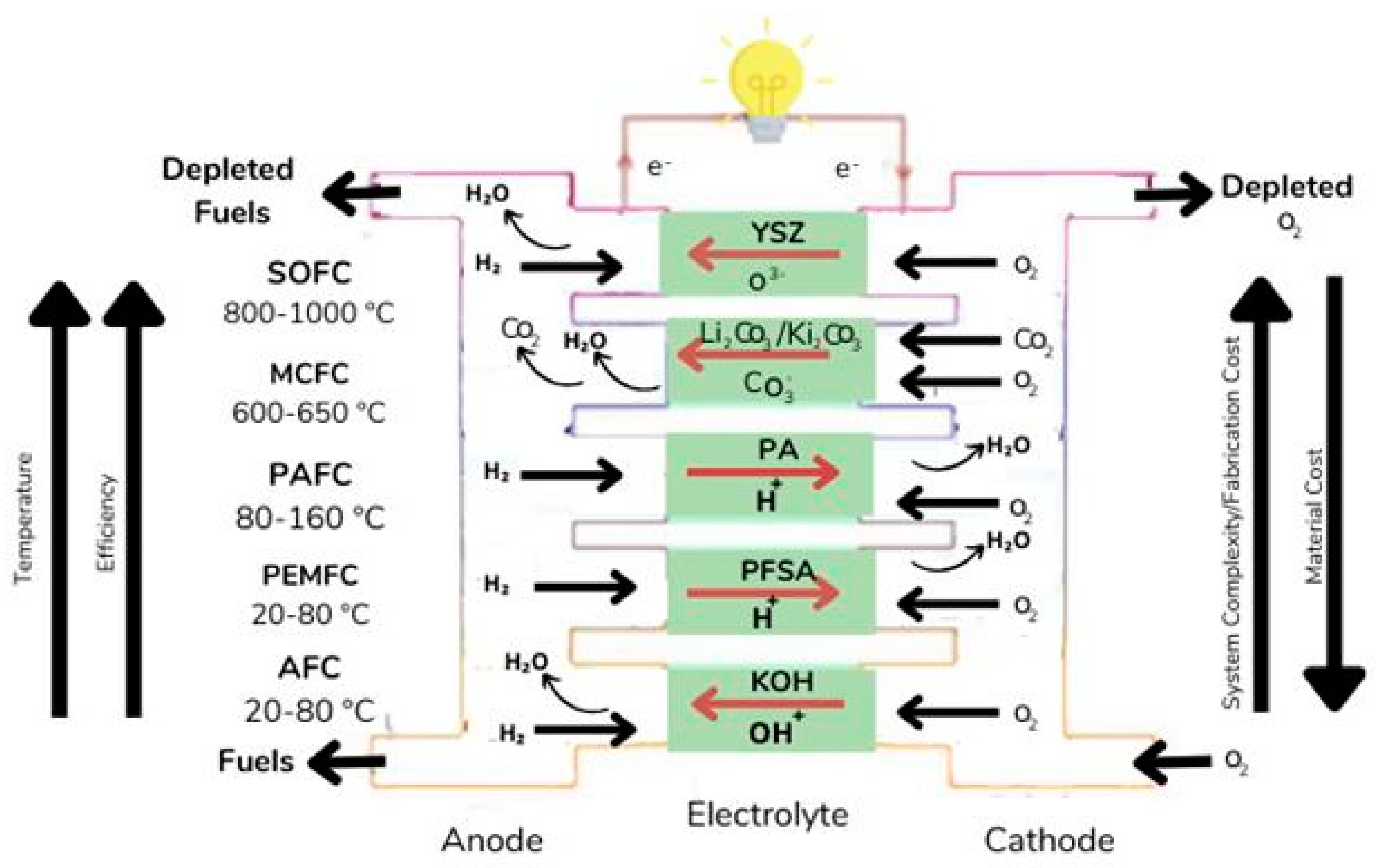
Figure 3.
An assembly of PEMFC [15].
Figure 3.
An assembly of PEMFC [15].
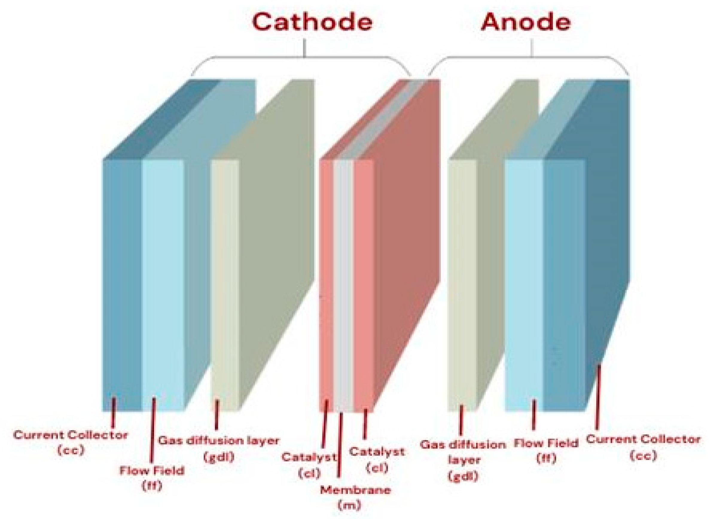
Figure 4.
Shows movement of electrons, protons and reactants in a catalyst layer [50].
Figure 4.
Shows movement of electrons, protons and reactants in a catalyst layer [50].
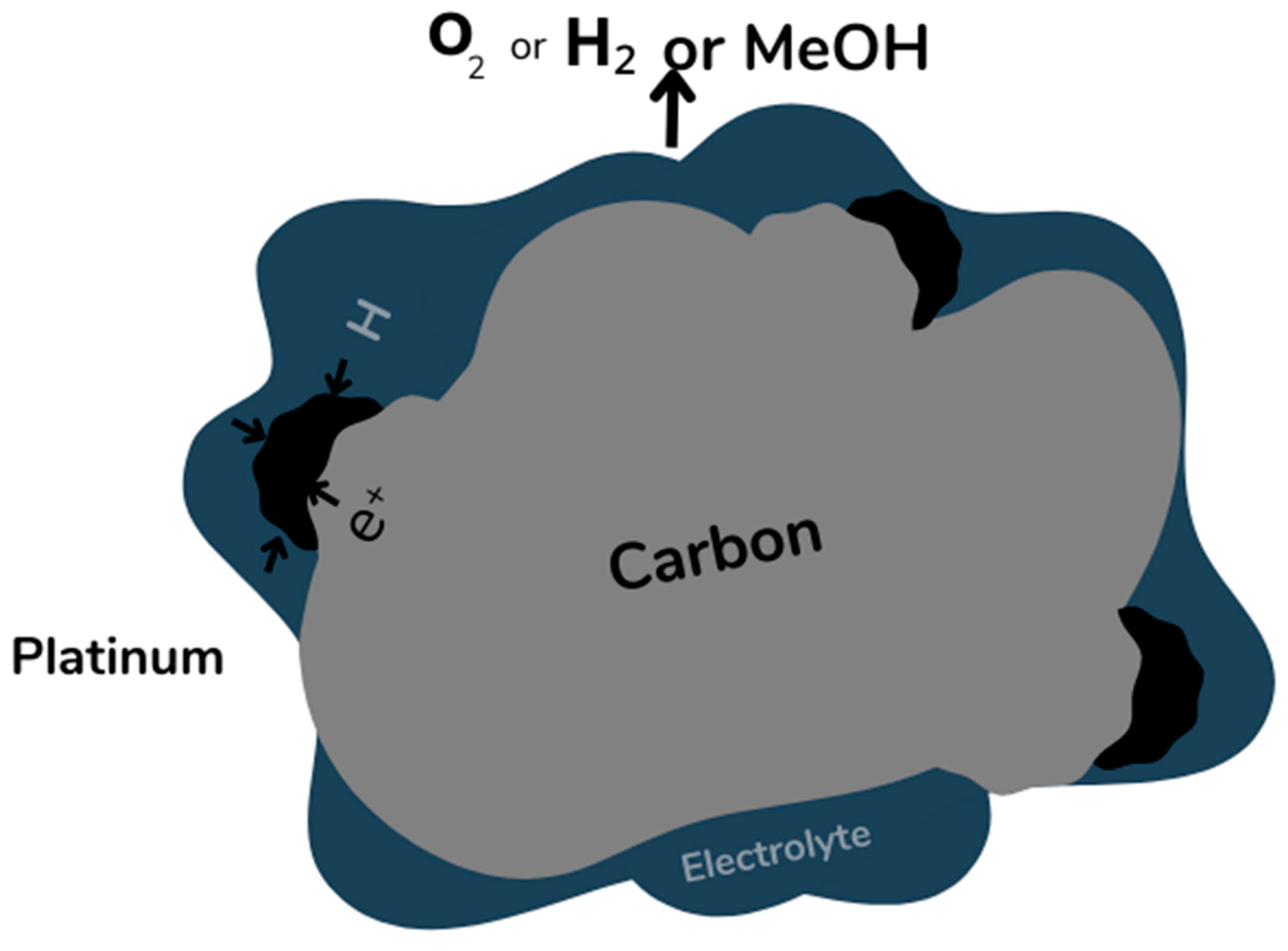
Table 1.
Showing types of fuel cells, their advantages and disadvantages [3].
Table 1.
Showing types of fuel cells, their advantages and disadvantages [3].
| Types of Fuel Cell | Advantages | Disadvantages |
|---|---|---|
| Reversible Fuel cell |
|
|
| Molten Carbonate Fuel Cell |
|
|
| Proton Exchange Membrane Fuel Cell |
|
|
| Direct methanol fuel cell |
|
|
| Reversible Fuel cell |
|
|
| Direct ammonia fuel cell |
|
|
| Alkaline fuel cell |
|
|
| Microbial Fuel Cells |
|
|
| Phosphoric acid fuel cell |
|
|
| Direct Propane Fuel Cell |
|
|
Table 2.
Illustrates the primary characteristics and manufacturing status of each type of fuel cell as of 2019 [6].
Table 2.
Illustrates the primary characteristics and manufacturing status of each type of fuel cell as of 2019 [6].
| PEMFCs | AFCs | SOFCs | MCFCs | PAFCS | |
|---|---|---|---|---|---|
| Electrolyte | Polymetric membrane | Potassium hydroxide | Ceramics | Molten carbonate | Phosphoric acid |
| Charge Carrier | H+ | OH- | O2- | CO32- | H+ |
| Operating temperature | -40 -1200 C | 50–200 oC | 500–1000 OC | 600–700 OC | 150–220 OC |
| Electrical efficiency | Up to 60–72% | Up to 70% | Up to 65% | Up to 60% | Up to 45% |
|
Primary fuel Primary applications |
H2 /methanol | Cracked ammonia/ H2 | Biogas/methane/ H2 | Biogas/methane/ H2 | H2/ reformed H2 |
| Shipment as of 2019 | 934.2 MW | 0 MW | 106.27 MW | 10.2 MW | 78.1 MW |
Disclaimer/Publisher’s Note: The statements, opinions and data contained in all publications are solely those of the individual author(s) and contributor(s) and not of MDPI and/or the editor(s). MDPI and/or the editor(s) disclaim responsibility for any injury to people or property resulting from any ideas, methods, instructions or products referred to in the content. |
© 2025 by the authors. Licensee MDPI, Basel, Switzerland. This article is an open access article distributed under the terms and conditions of the Creative Commons Attribution (CC BY) license (http://creativecommons.org/licenses/by/4.0/).
Copyright: This open access article is published under a Creative Commons CC BY 4.0 license, which permit the free download, distribution, and reuse, provided that the author and preprint are cited in any reuse.


