
Submitted:
03 January 2025
Posted:
03 January 2025
You are already at the latest version
Abstract
In the process of extracting the centerline of laser streaks in complex deep-hole cavities, burrs as well as cluttered low-frequency random noise often appear in the point cloud data acquired by traditional image processing methods. To address this issue, this study proposes a point cloud post-processing method based on the Minimum Spanning Tree (MST) and Depth-First Search (DFS) algorithms. First, the Steger algorithm is used to generate a subpixel point cloud model containing noise. Then, an effective connectivity structure of the point cloud is constructed using MST, and the DFS algorithm is applied for path searching of the main contour and noise elimination. The proposed method can accurately extract laser stripe centerlines from complex parts, significantly improving the extraction accuracy. Experimental results show that, after applying the MST and DFS methods, low-frequency noise is effectively removed, and the extraction results are highly consistent with manual methods. The Dice similarity coefficient approaches 1, and the maximum Hausdorff distance is only 3.3821 pixels. This method provides an efficient and reliable solution for the precise extraction of complex laser stripes and lays a solid data foundation for subsequent feature parameter calculation and 3D reconstruction.
Keywords:
Laser Stripe Centerline Extraction
; Minimum Spanning Tree
; Depth-First Search
; Point Cloud Post-Processing
; Noise Removal
1. Introduction
In contemporary manufacturing, with continuous technological advancements, the precision machining and quality inspection of complex components have become core processes, with the accurate measurement and analysis of complex deep-hole internal structures being particularly crucial. Our research team previously used the annular light sectioning method to measure the diameter of steel pipe components and completed the 3D reconstruction of their internal surface point clouds [1,2]. The object of study is a relatively simple steel tube part with an internal structure close to a smooth bore morphology, which is suitable for the application of existing algorithms such as Steger, Canny, Sobel, Prewitt, Roberts, etc. [3,4,5] to extract the contour of the annular laser beam quickly and accurately. However, this write-up algorithm faces many challenges when applied to the detection of inner walls with complex geometries (e.g., internal gears, splines, gun barrel bore, etc.) [6]. The internal walls of these components have complex geometries, with surface roughness, machining tool marks, and surface reflection characteristics, all of which can alter the interaction between the laser and the material, resulting in uneven laser energy distribution and discontinuous laser stripes [7]. Due to the combined effects of the internal wall’s complex shape and material properties, the laser stripes exhibit unpredictable and highly variable characteristics, significantly increasing the difficulty of subsequent laser stripe centerline extraction [8].
In traditional methods, such as applying the Steger algorithm to extract the laser stripe centerlines of complex internal shapes (e.g., lobed, internal gears, splines, internal octagonal shapes, etc.), issues such as burrs, low-frequency noise, and redundant branches commonly arise. These issues significantly affect the accuracy and completeness of the extraction results, failing to meet the requirements for high-precision measurement and accurate analysis of complex components [9]. Building on previous research, our team used self-developed deep-hole detection equipment to capture laser stripe images of the internal surfaces of various deep-hole components, applying the Steger algorithm for point cloud extraction of laser stripes of different shapes. Experimental results indicated that while the Steger algorithm is suitable for extracting simple laser stripes, its performance degrades when applied to complex laser stripes, often generating low-frequency random noise signals. These signals, with small amplitudes and close to the variations of the measured surface, manifest as burrs or erratic branching points [10]. Nevertheless, the Steger algorithm still retains detail information of the contours during the overall extraction process, yet automatically identifying the precise centerline of the laser stripes from noise and subpixel point cloud data remains a significant challenge in the field of complex laser stripe extraction [11]. Traditional methods typically rely on manual noise removal to obtain a complete contour, which is time-consuming and prone to human error, thereby affecting the accuracy of subsequent feature parameter calculations and 3D reconstruction.
To address this issue, this study proposes an efficient alternative method aimed at automatically extracting complete contour curves from noisy point cloud data, with the goal of providing an effective solution for precise extraction of complex contours. Currently, research in laser stripe extraction often relies on adaptive improvements to existing mature algorithms. Typical improvements include the enhanced Hessian matrix [12,13], gray gravity method [14], DBSCAN [15], adaptive bidirectional grayscale methods [16], and adaptive convolution techniques [17,18,19]. While these methods have shown some success in specific tasks, their widespread application in industry remains unverified, and they often require further optimization and adjustment in practical applications, making it difficult to achieve breakthrough progress.
In this context, this study innovatively proposes a laser stripe centerline extraction method based on minimum spanning tree (MST) with depth-first search (DFS) for complex deep bore internal cavities. The study begins by using the Steger algorithm to generate a subpixel point cloud model containing noise, followed by the application of MST and DFS for main contour searching and tracking. This approach effectively removes interference from point cloud data, accurately obtaining the point cloud coordinates of the laser stripe’s geometric center. The method fully exploits the MST’s advantage in constructing an effective connectivity structure of point cloud data, ensuring reasonable connections between points, and combines the traversal and pathfinding capabilities of DFS to precisely search and track the main contour. This approach acts as an efficient noise filter, systematically removing burrs, erratic branches, and other noise points, thereby ultimately and accurately obtaining the point cloud coordinates of the laser stripe’s geometric center. This provides reliable data support for subsequent feature parameter calculations, 3D reconstruction, and further analysis [20].
2. Analysis of Laser Stripe Characteristics in Complex Deep-Hole Geometries
In the field of image processing, HALCON is a commercially available computer vision software library that has been widely validated through industrial applications, demonstrating excellent reliability and efficiency. The linesgauss operator in HALCON, based on the core of the Steger algorithm, Sis capable of effectively detecting various geometric shapes, such as straight lines, curves, arcs, elliptical arcs, and waveforms. This algorithm is an efficient line feature extraction method, particularly outstanding in applications that require high precision and subpixel-level edge detection. In the previous research, Steger algorithm was successfully applied to the point cloud extraction of the laser stripe centerline on the inner surface of a deep hole part, and significant results were achieved. Therefore, this study first applies the Steger algorithm to extract the laser stripe centerlines from contours of varying complexities, aiming to investigate the performance of the algorithm in such applications.
Figure 1 (a) shows the laser stripe image of a smooth deep hole, while Figure 1 (b) presents a 3D intensity distribution of the grayscale values from the image. It is evident from the figure that the laser stripe is uniformly distributed and has a simple contour shape. Figure 1 (c) shows the result of the laser stripe centerline extraction using the Steger algorithm, and Figure 1 (d) is a local zoomed-in view of the extracted result. From these results, it is clear that the Steger algorithm performs well in extracting the centerline of laser stripes with simple contours. The algorithm accurately extracts a subpixel contour curve, facilitating subsequent contour feature parameter calculations and 3D reconstruction.
Figure 2 (a) shows an image of the contour of the flap laser stripe, which exhibits an annular distribution consisting of a combination of straight lines and circular arcs. Figure 2(b), on the other hand, shows the three-dimensional distribution of the gray intensity of this image. It can be observed that there is an obvious abrupt change in the gray intensity at the junction of straight lines and circular arcs, which leads to an uneven energy distribution of the laser stripes. Figure 2(c) demonstrates the results of the laser stripe centerline extracted using Steger’s algorithm (after optimizing the parameters), and Figure 2(d) is a local zoomed-in view of the laser stripe center extraction results. It can be clearly seen that the algorithm identifies multiple line segments, and the figure distinguishes the extracted line segments with different colors, which is again very different from the extraction result of the laser stripe centerline of the smooth hole in Figure 2(c) above, and there are many burr noises in the junction of the straight line and the circular arc. This kind of gray scale mutation easily causes Steger’s algorithm to misidentify the pseudo edges, which poses a challenge to the extraction of the centerline.
This The inner surface of an internal gear has a complex shape and can be considered as one of the representatives for the extraction of complex laser stripe centerlines. Figure 3 (a) shows the grayscale image of the laser stripes on the inner surface of the internal gear. It can be observed that the laser stripe intensity distribution is uneven, with alternating light and dark areas, which significantly differs from the laser stripe grayscale image of the smooth deep hole surface. Figure 3 (b) presents the 3D intensity distribution of the laser stripes on the internal gear. From the figure, it is clear that there is a significant grayscale intensity difference between the tooth crest, tooth root, and the involute surface. The laser stripe intensity is higher on the tooth crest and tooth root, while the intensity on the involute surface is relatively lower. The main reason for this phenomenon lies in the fact that the optical flux generated by the annular laser beam is uniform within a unit angle. However, within the same angular range, the length of the involute curve is greater than that of the tooth crest and tooth root curves, resulting in lower optical intensity per unit length on the involute curve, and higher intensity on the tooth crest and tooth root curves. Additionally, the variation in laser stripe grayscale intensity is influenced by factors such as surface roughness, machining tool marks, and surface reflectivity.
Figure 3 (c) shows the result of the laser stripe centerline extraction on the internal gear using the Steger algorithm, and Figure 3 (d) provides a local zoom-in of the extracted result. It can be clearly seen that the algorithm identifies multiple line segments, distinguishing them by different colors. However, in the zoomed-in subpixel point cloud, numerous noise points can be observed, appearing as burrs or chaotic branch points. Despite this, the overall extraction effectively retains the detailed information of the internal gear contour. By manually removing the noise points, a complete contour of the internal gear can be obtained.
Figure 4 (a) shows the grayscale image of the laser stripes on the surface of a rectangular spline. From the image, it can be observed that the laser stripe intensity distribution is similar to that of the internal gear surface. Figure 4 (b) displays the 3D intensity distribution of the laser stripes on the rectangular spline. It is clearly evident that the laser stripe intensity is higher in the arc regions, while the intensity is relatively lower in the rectangular keyway areas. This phenomenon is similar to the behavior observed in the internal gear laser stripes and is mainly influenced by a combination of factors, including the inner surface profile shape, surface roughness, machining tool marks, and surface reflectivity. Figure 4 (c) presents the result of laser stripe centerline extraction on the rectangular spline using the Steger algorithm, and Figure 4 (d) shows a local zoom-in of the extracted result. From the images, it is clear that the algorithm successfully identifies multiple line segments, with different colors representing different segments. However, in the zoomed-in subpixel point cloud, a large number of noise points can be observed, which primarily appear as burrs or chaotic branch points. Despite this, the overall extraction process retains the detailed information of the rectangular spline contour quite effectively.
Figure 5 presents the feature analysis and geometric centerline extraction results of the internal octagonal laser stripe image. Figure 5 (a) shows the grayscale image of the internal octagonal laser stripes, where the stripe distribution exhibits a regular octagonal pattern, with the stripe intensity more evenly distributed along the edges. Figure 5 (b) presents the 3D grayscale distribution of the image. From this, it is clear that the grayscale intensity along one edge of the octagon is higher, while the intensity along the other edges remains relatively uniform, with a few points showing sudden intensity changes. This distribution characteristic is closely related to surface shape, roughness, machining tool marks, and reflective properties. Figure 5 (c) displays the result of the geometric centerline extraction of the internal octagonal laser stripes based on the Steger algorithm, with different colors used to distinguish each line segment. The overall extraction result is relatively clear. Figure 5 (d) provides a local zoom-in of the extracted result, where the details of the local line segments can be clearly observed. However, at the junctions of these segments, multiple line segments are identified, with numerous noise points and chaotic branches appearing.
In summary, for images with simple shape contours and uniform energy intensity distribution, the mature Steger algorithm can accurately extract the centerline of the laser stripes. However, when dealing with complex laser stripe images, the limitations of this algorithm become apparent. These parts, due to their complex inner surface shapes, varying roughness, random machining tool marks, diverse reflective properties, and the combined effects of laser and sensor system errors, result in low-frequency random noise signals in the subpixel contour point cloud data extracted by the Steger algorithm. This error is difficult to fully eliminate. The main issues with the Steger algorithm in complex laser stripe centerline extraction are as follows:
Shape Complexity: Complex contours, such as petals, internal gears, rectangular splines, etc., include multiple concave and convex structures, and the internal structural differences may lead to uneven illumination, thereby reducing image contrast and significantly affecting the extraction results.
Noise Interference: Reflections from the metal surface or machining marks are easily misidentified as edges, increasing the difficulty and complexity of stripe recognition.
Curvature Variation: At the junctions of straight lines with straight lines, straight lines with arcs, or arcs with arcs, large curvature variations are common, which can cause discontinuities in the extraction results or generate spurious edges.
Parameter Adjustment Limitations: Although the Steger operator can improve extraction results through parameter adjustments, for complex shapes such as petals, internal gears, rectangular splines, and internal octagons, relying solely on parameter adjustments cannot achieve ideal detection outcomes.
These limitations significantly affect the direct application of the Steger algorithm in complex laser stripe centerline extraction. However, from an overall extraction perspective, the Steger algorithm still retains the contour’s detailed information relatively well. Currently, complete contours are obtained by manually removing noisy points from point cloud data containing noise, which is a time-consuming and human-influenced process. Therefore, this study proposes an efficient method to automatically extract a complete contour curve from point cloud data containing noise points, providing an effective solution for the precise extraction of complex contours.
3. Methodology
Based on the above laser stripe extraction results, it can be seen that the Steger algorithm has some limitations in dealing with complex laser stripe centerlines. Nevertheless, it can be observed from the extraction results of the algorithm that the details of the laser stripes are still well preserved. However, the extracted sub-pixel point cloud contains a large number of noise points and cluttered branching lines. Therefore, we can post-process the sub-pixel point cloud of laser stripes extracted by Steger’s algorithm, and use mathematical methods to quickly eliminate the noise points in the point cloud, so as to obtain accurate geometric center point cloud data. To this end, this study proposes a method combining minimum spanning tree and depth-first search for effective data processing of point clouds containing noise points.
3.1. Minimum Spanning Tree (MST)
The A minimum spanning tree is a subgraph of an undirected weighted graph that connects all vertices and has no rings, and whose total edge weights are minimized. In this study, the coordinates of a sub-pixel point cloud containing noise points can be viewed as an undirected weighted subgraph and the minimum spanning tree can be realized by the greedy algorithm Prim algorithm. The algorithm starts from a starting node and expands gradually, connecting the unvisited nodes by selecting edges with the minimum weight, where an edge is a connecting line between two points.
Mathematically, let G = (V, E) be a connected undirected graph, where V is the set of vertices, E is the set of edges, and W is the weight function for the edges. The goal is to find the minimum spanning tree T of G, where the edge set of E(T) ⊆ E, satisfies:
- ➢
- T is a connected and acyclic subgraph.
- ➢
- |E(T)| = |V| − 1.
- ➢
- The total weight is minimized.
The steps for generating the MST are as follows:
Initialization:
- Select an initial vertex v0 ∈ V.
- Define the set A = {v0} to represent the visited vertices.
- Define the set E(T) = ∅ represent the edges of the spanning tree.
Iteration:
- While A ≠ V, repeat the following steps:
- Choose an edge (u, v) ∈ E in E such that u ∈ A and v ∈ V\A, and w(u, v) is minimal.
- Add edge (u, v) to E(T), i.e., E(T) = E(T) ∪ {(u, v)}.
- Add vertex v to the set A, i.e., A = A ∪ {v}.
Output:
- When A = V, (V, E(T)) is the minimum spanning tree.
- The total weight is .
As shown in Figure 6, four sets of random points are generated in a 2D plane, each consisting of 9 points labeled: A, B, C, D, E, F, G, H, and I. The Euclidean distance is used to calculate the distance between each pair of points, and the numbers on one side of each line represent the edge weights. This forms a weighted connected graph. The Prim algorithm is then used to construct the MST from the weighted connected graph. The red line segments in the figure represent the MST, where all vertices are connected, and the total edge length between all points is minimized. The process involves gradually selecting the edge with the smallest weight at each step, ensuring that each connected vertex is part of the MST.
3.2. Depth-First Search (DFS)
Depth-first search (DFS) is an algorithm for traversing a search tree or graph. The algorithm starts from a starting node and visits nodes as deeply as possible along a path until it reaches a node where it is not possible to proceed further, and then backtracks to the previous node to continue exploring other paths. This process is carried out recursively, by visiting sub-nodes deeper and deeper until the complete sub-graph is traversed. Since MSTs are acyclic connected trees where the path from one node to another is unique, DFS can be used to find the path from the starting node to the terminating node in a minimum spanning tree. As shown in Figure 7, the maximum and minimum value points in the Y-axis direction are selected as the start and termination points in the MST, and the unique path from the start point to the termination point found using DFS is shown in Figure 7, where the green line segment indicates the path searched by the DFS’s in the MTS, which demonstrates its unique advantage in exploring complex structures.
In this study, we employ a MST to construct the basic connectivity structure of the point cloud data. The acyclic nature of the MST ensures the existence of unique paths between points. Based on this, we apply a DFS algorithm to traverse the entire tree structure from a specified start node until reaching a predetermined termination node to identify and eliminate points that do not match the expected path. Through four sets of random cases, we thoroughly explore a path search method that combines the principles of Minimum Spanning Tree (MST) and Depth-First Search (DFS). Simulation results indicate that this method can effectively remove spurious and cluttered branch interference points from point cloud data containing noise points, and successfully identify the unique path between the start and end points. Therefore, this method is suitable for extracting the centerline of complex laser stripes.
4. Experiment and Analysis
To In Section 3 of this paper, we detailed a complex laser stripe centerline extraction method based on the Minimum Spanning Tree (MST) and Depth-First Search (DFS). This method was initially verified for feasibility using four sets of random data. In this section, we apply the proposed algorithm to extract laser stripe centerlines for complex shapes, including petal-shaped, internal gear, rectangular spline, and internal octagonal patterns. To better present the results, this study uses a segmented approach to display the extraction outcomes. The specific steps of the overall algorithm are as follows:
- ➢
- Convert the sub-pixel point cloud coordinates to relative positions with respect to a specific origin and calculate the polar coordinates (angle) for each point.
- ➢
- Divide the angle range into multiple segments (for example, each 45° as one segment) for segmented processing.
- ➢
- For each segment, extract the points within the specified angle range and compute the Euclidean distance between each pair of points to construct the distance matrix.
- ➢
- Use the Prim algorithm to construct the MST from the distance matrix, ensuring that within each angular segment, all points are connected with the minimum total edge length.
- ➢
- For each angular segment, select the starting and ending points: the point closest to the starting angle of the segment is chosen as the starting point. This is done by calculating the absolute difference between each point’s angle and the starting angle, and selecting the point with the smallest difference as the starting point. Similarly, the point closest to the ending angle is selected as the ending point.
- ➢
- Find the path from the start point to the end point on a minimal spanning tree using DFS and visualize it.
By following these steps, the extracted complex laser stripe centerlines for different shapes are shown in Figure 8, Figure 9, Figure 10 and Figure 11. To better demonstrate the advantages of the MST and DFS-based method in extracting complex laser stripe centerlines, we compare the extraction results with the original point cloud coordinates. The blue section in the figure represents the subpixel point cloud data extracted using the Steger algorithm, while the red section represents the laser stripe center coordinates automatically extracted using the MST and DFS algorithms. After performing multiple experiments on 32 different shape samples, the results indicate that the proposed MST and DFS-based method excels in extracting centerlines from complex laser stripes. This method can effectively remove spurious and erratic branch points from point clouds containing noise, ensuring that the extracted centerlines are coherent and smooth. These results validate the stability and practicality of the algorithm.
Dice Similarity Coefficient (DSC):
The Dice Similarity Coefficient (DSC) is a statistical measure used to assess the similarity between two sample sets. Its value ranges from 0 to 1, where 1 indicates perfect overlap and 0 indicates no intersection. In this study, the DSC is used to compare the overlap between the centerline extraction results based on MST and DFS with the manually extracted results. The formula is as follows:
where X and Y represent the pixel sets of the automated segmentation and the manual segmentation, respectively.
Hausdorff Distance (HD):
The Hausdorff Distance (HD) is a metric used to measure the maximum distance between two sets. It quantifies the greatest deviation between the boundaries of the two sets. In this study, the HD is used to evaluate the maximum distance between the boundary of the laser stripe centerline extracted using the MST and DFS methods and the boundary of the manually extracted centerline. It is defined as:
where d(x,y)d(x, y) is the Euclidean distance between points x and y, and sup and inf represent the supremum and infimum, respectively.
This study evaluated the performance of laser stripe centerline extraction for four different test objects: petal shape, internal gear, spline, and internal octagon. Figure 12 shows the laser stripe centerline extraction results based on MTS and DFS methods, alongside the manually extracted results. The first row presents the automatic extraction results using MTS and DFS, while the second row shows the manually extracted results. As can be seen from the figure, the extraction results based on the MTS and DFS methods are highly similar to the manually extracted results. This similarity is further demonstrated in the evaluation using the DSC and HD, with the specific values shown in Table 1.
The evaluation metrics indicate that the DSC values for all test objects are very close to 1, with specific values of 0.9986 for petal shape, 0.9987 for internal gear, 0.9953 for spline, and 0.9992 for internal octagon. These results demonstrate that the overlap between the laser stripe centerline extraction results based on MTS and DFS methods and the manually extracted results is extremely high, almost identical. This high consistency reflects the universality and accuracy of the algorithm across different shapes. The maximum HD value is 3.3821 pixels for the petal shape, with other objects showing HD values of 1.6414 for internal gear, 2.0000 for spline, and 0.9653 for internal octagon. These results suggest that the maximum boundary deviation between the MTS and DFS extraction results and the manually extracted results is minimal, confirming the effectiveness of the algorithm in precise localization and boundary preservation.
Combining the results of DSC and HD, it can be concluded that the MTS and DFS-based laser stripe centerline method demonstrates extremely high accuracy and consistency across test objects with various shapes and sizes. The DSC values close to 1 indicate that the extraction results are almost identical to the manual reference, while the low HD values further validate the algorithm’s excellent performance in boundary accuracy. Together, these metrics demonstrate the good adaptability and robustness of the proposed method for center extraction of complex laser fringes.
5. Discussion
In this study, we approached the laser stripe centerline extraction problem from the perspective of path planning and proposed a mathematical method based on MTS and DFS. The advantage of this method lies in its ability to search and trace the main contour along the target region in a point cloud model containing noise, effectively eliminating interference from burrs and chaotic branches, and accurately identifying and locating the geometric center coordinates of the laser stripe.
The study was conducted to extract the centerline of several complex laser stripes of different shapes and sizes, and the DSC and HD metrics were used to evaluate the similarity and difference between the laser stripe extraction results of MTS and DFS and the manual extraction results. The experimental results show that the similarity DSC of the point cloud data extracted with this method and the manually selected point cloud data are all close to 1, and the maximum difference HD is 3.3821pixel. Compared with other methods [21,22], the laser stripe extraction method based on MTS and DFS is better than the metrics of CPM and DRLSE in terms of DSC and HD, and the extraction results have a higher accuracy and better performance, which fully verifies that the method has good adaptability and robustness in complex laser streak center extraction.
This method offers reliable technical support for feature parameter calculation and 3D reconstruction measurements of deep hole inner surfaces. With the increasing demand for 3D reconstruction of complex components, the MTS and DFS-based complex laser stripe extraction method will demonstrate its enormous potential.
Author Contributions
Conceptualization, D.Y. and H.D.; methodology, H.D.; software, X.Z. and H.D.; validation, D.Y., H.D. and Z.Z.; formal analysis, X,Z. and D.Y.; investigation, H.D., Z.Z. and D.Y.; resources, Y.D.; data curation, Z.Z. and H.D.; writing—original draft preparation, H.D.; writing—review and editing, H.D.,D.Y.,X.Z. and Z.Z.; visualization, H.D. and X,Z.; project administration, D.Y.; funding acquisition, D.Y. All authors have read and agreed to the published version of the manuscript.
Funding
This research was funded by the National Natural Science Foundation of China (grant number 51875532) and the Central Guidance for Local Scientific and Technological Development Funding Projects (grant number YDZJSX2022C006).
Institutional Review Board Statement
Not applicable.
Informed Consent Statement
The authors declare that they consent to participate this paper.
Data Availability Statement
Data are contained within the article.
Acknowledgments
The authors would like to sincerely thank all other members of the research team for their contributions to this research.
Conflicts of Interest
The authors declare no conflicts of interest.
References
- Du, H.; Zhao, X.; Yu, D.; Shi, H.; Zhou, Z. Research on Point Cloud Acquisition and Calibration of Deep Hole Inner Surfaces Based on Collimated Ring Laser Beams. Sensors 2024, 24, 5790. [CrossRef]
- Zhao, X.; Du, H.; Yu, D. Improving Measurement Accuracy of Deep Hole Measurement Instruments through Perspective Transformation. Sensors 2024, 24, 3158. [CrossRef]
- Steger, C. An Unbiased Detector of Curvilinear Structures. IEEE Trans. Pattern Anal. Mach. Intell. 1998, 20, 113–125. [CrossRef]
- Steger, C. Extraction of curved lines from images. In Proceedings of the 13th International Conference on Pattern Recognition.1996,2, 251–255. [CrossRef]
- Steger, C. Extracting curvilinear structures: A differential geometric approach. Computer Vision — ECCV ’96’ .1996,1064,630-641. [CrossRef]
- Abidin Z Z, Asmai S A, Abas Z A, et al. Development of Edge Detection for Image Segmentation[C]//IOP Conference Series: Materials Science and Engineering. IOP Publishing, 2020, 864(1): 012058. [CrossRef]
- Yang T, Wu S, Zhang S, et al. A robust and accurate centerline extraction method of multiple laser stripe for complex 3D measurement. Advanced Engineering Informatics, 2023, 58: 102207. [CrossRef]
- He Z, Kang L, Zhao X, et al. Robust laser stripe extraction for 3D measurement of complex objects. Measurement Science and Technology, 2021, 32(6): 065002. [CrossRef]
- Zhao H, Liu X, Wang S, et al. An enhanced centerline extraction algorithm for complex stripes in linear laser scanning measurement. Precision Engineering, 2024, 91: 199-211. [CrossRef]
- Abzal A, Saadatseresht M, Varshosaz M, et al. Development of an automatic map drawing system for ancient bas-reliefs. Journal of Cultural Heritage, 2020, 45: 204-214. [CrossRef]
- Wan M, Wang S, Zhao H, et al. Robust and accurate sub-pixel extraction method of laser stripes in complex circumstances. Applied Optics, 2021, 60(36): 11196-11204. [CrossRef]
- Bo Q, Hou B, Miao Z, et al. Laser stripe center extraction method base on hessian matrix improved by stripe width precise calculation. Optics and Lasers in Engineering, 2024, 172: 107896. [CrossRef]
- Li Z, Ma L, Long X, et al. Hardware-oriented algorithm for high-speed laser centerline extraction based on Hessian matrix. IEEE Transactions on Instrumentation and Measurement, 2021, 70: 1-14. [CrossRef]
- Li Y, Zhou J, Huang F, et al. Sub-pixel extraction of laser stripe center using an improved gray-gravity method. Sensors, 2017, 17(4): 814. [CrossRef]
- Yang P, Yang Z, Zhang J, et al. Accurate extraction method of multi-laser stripes for stereo-vision based handheld scanners in complex circumstances. Optics & Laser Technology, 2025, 181: 111605. [CrossRef]
- Zhang M, Li Z, Zhang F, et al. Adaptive bidirectional gray-scale center of gravity extraction algorithm of laser stripes. Sensors, 2022, 22(24): 9567. [CrossRef]
- Yin X Q, Tao W, Feng Y Y, et al. Laser stripe extraction method in industrial environments utilizing self-adaptive convolution technique. Applied Optics, 2017, 56(10): 2653-2660. [CrossRef]
- Ye C, Feng W, Wang Q, et al. Laser stripe segmentation and centerline extraction based on 3D scanning imaging. Applied Optics, 2022, 61(18): 5409-5418. [CrossRef]
- Zhao H, Liu X, Wang S, et al. An enhanced centerline extraction algorithm for complex stripes in linear laser scanning measurement. Precision Engineering, 2024, 91: 199-211. [CrossRef]
- Sheng Y, Li J. Fast and accurate centerline extraction algorithm for a laser stripe applied for shoe outsole inspection. Applied Optics, 2023, 62(2): 314-324. [CrossRef]
- Huang Y, Hu G, Ji C, et al. Glass-cutting medical images via a mechanical image segmentation method based on crack propagation. Nature Communications, 2020, 11(1): 5669. [CrossRef]
- Li X, Li C, Liu H, et al. A modified level set algorithm based on point distance shape constraint for lesion and organ segmentation. Physica Medica, 2019, 57: 123-136. [CrossRef]
Figure 1.
Feature Analysis and Geometric Centerline Extraction of Smooth Deep-Hole Laser Stripes.

Figure 2.
Feature Analysis and Geometric Centerline Extraction of the petal-shaped Laser Stripes.
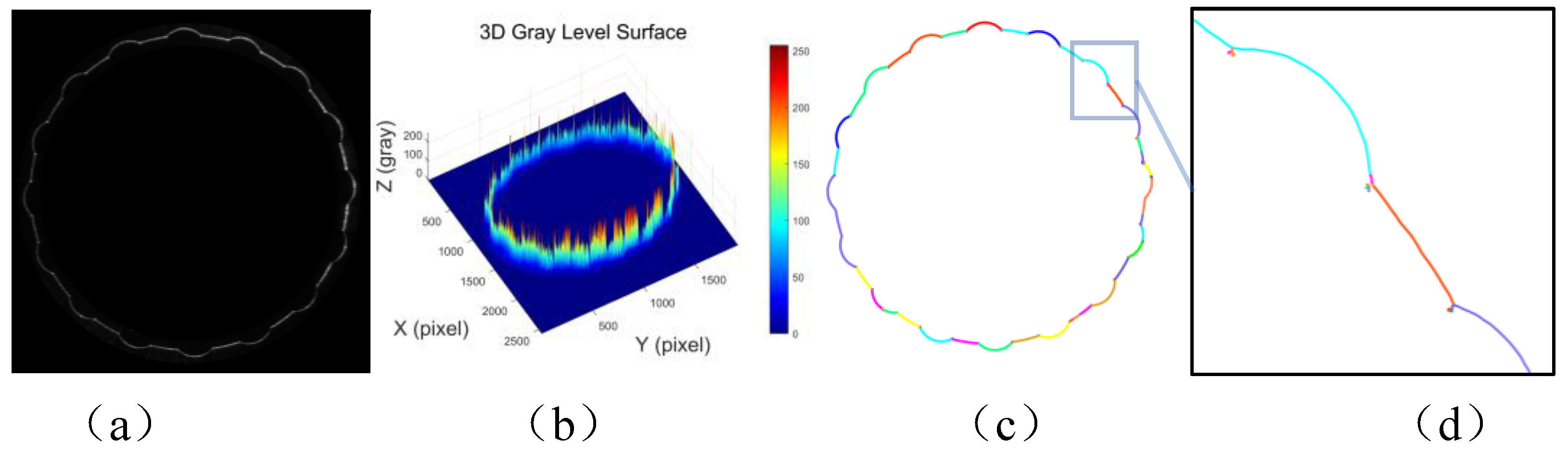
Figure 3.
Feature Analysis and Geometric Centerline Extraction of Internal Gear Laser Stripes.
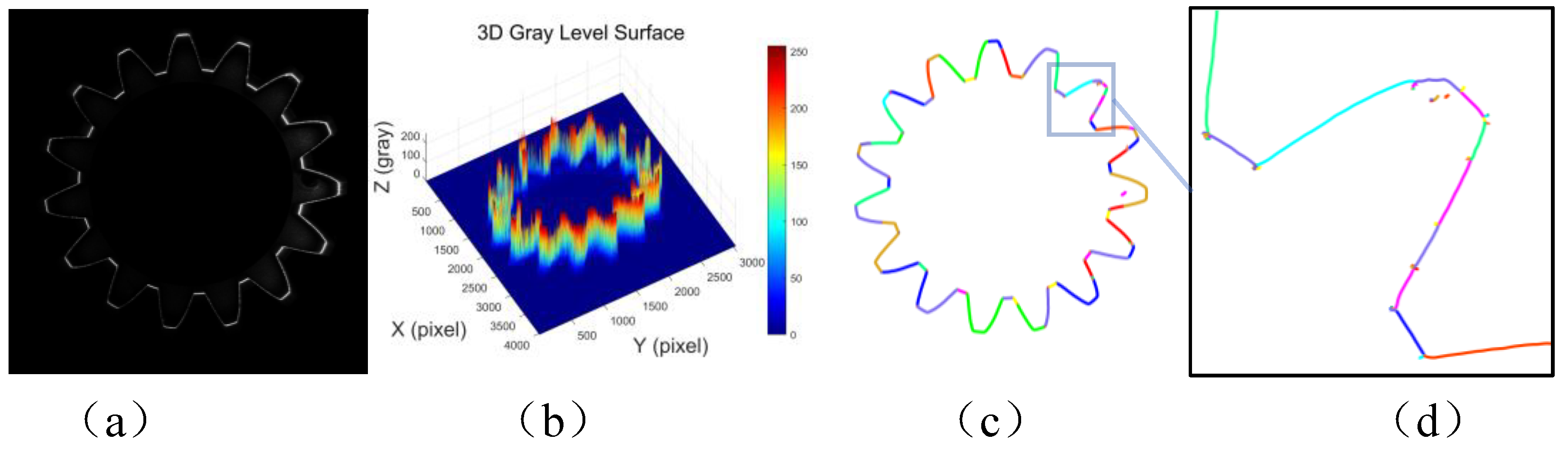
Figure 4.
Feature Analysis and Geometric Centerline Extraction of Rectangular Spline Laser Stripes.
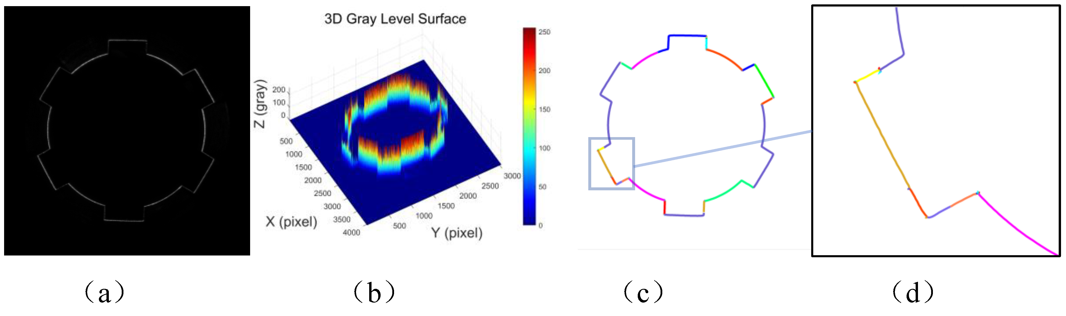
Figure 5.
Feature Analysis and Geometric Centerline Extraction of Internal Octagonal Laser Stripes.
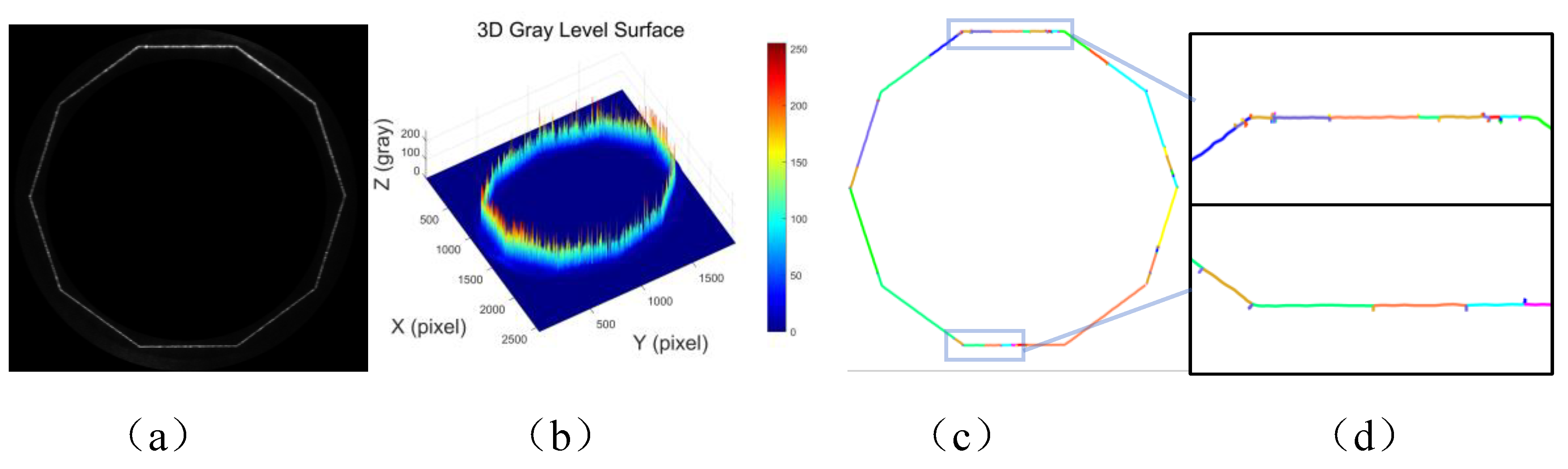
Figure 6.
Minimum Spanning Tree Generation Example.
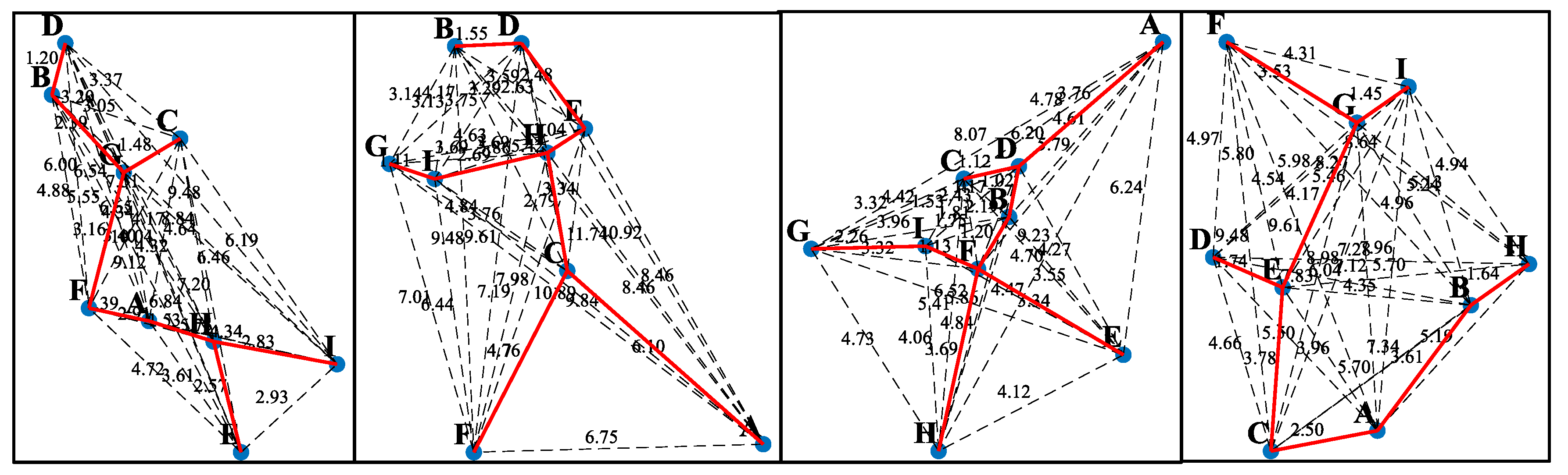
Figure 7.
DFS Path Search Example in MST.
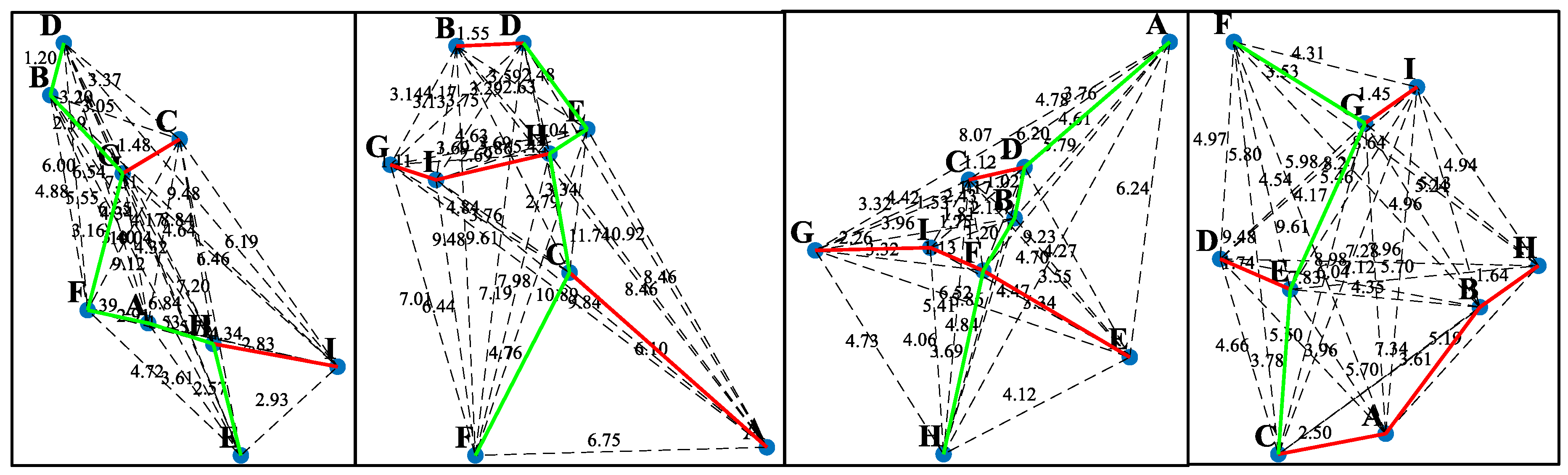
Figure 8.
Extraction results of the petal-shaped laser stripe centerline.
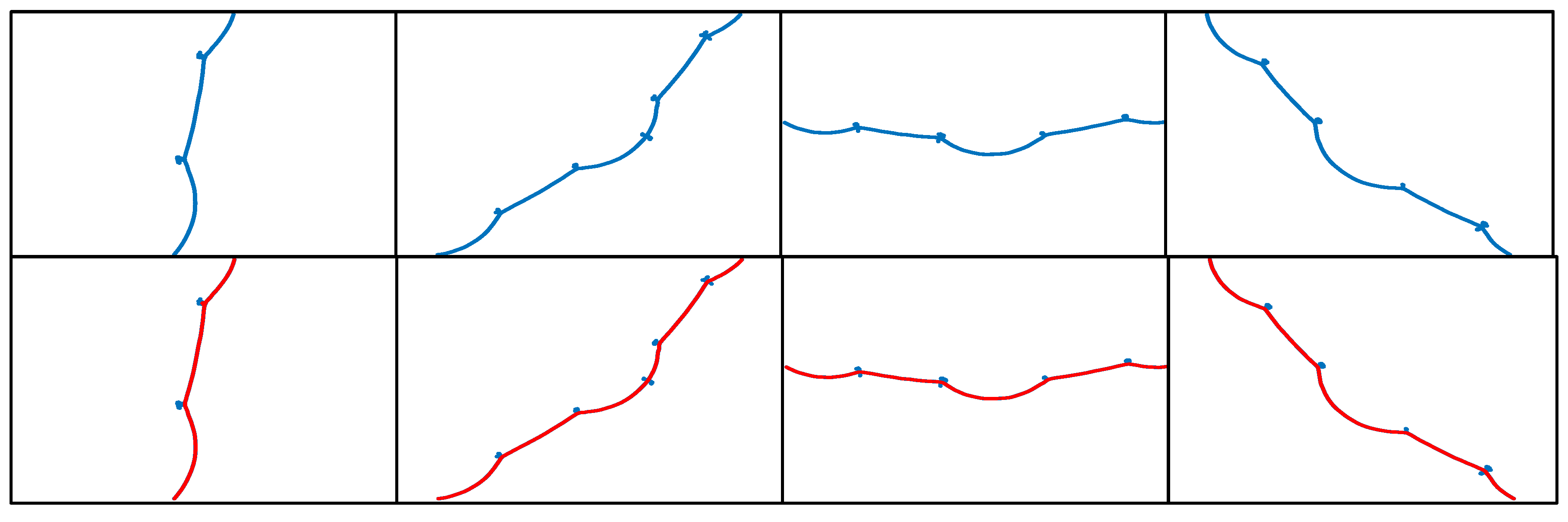
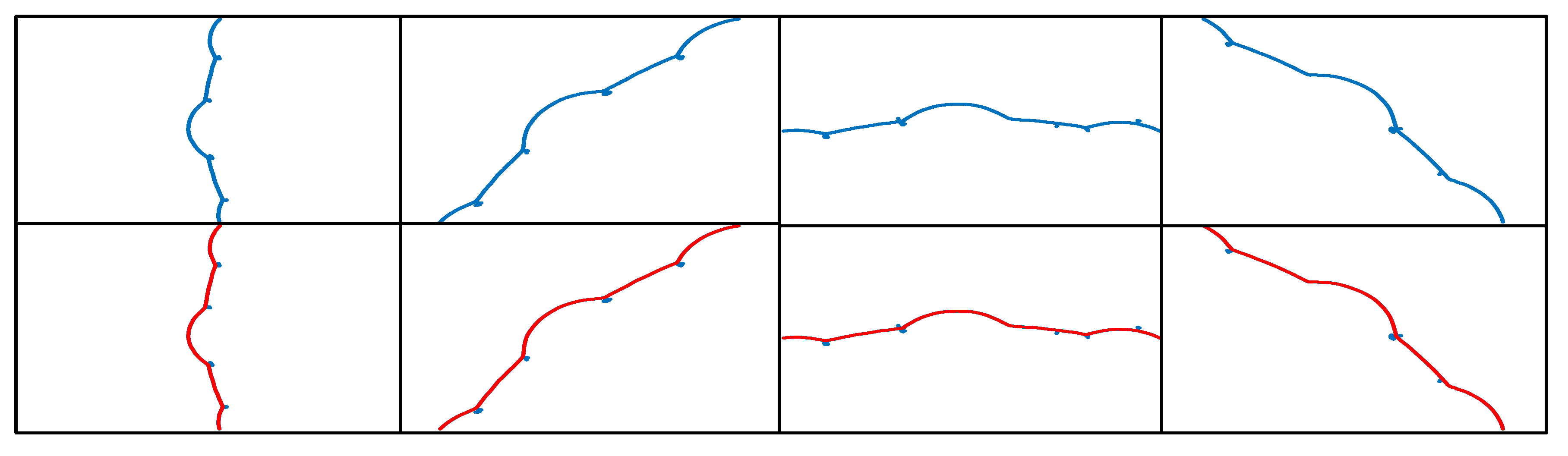
Figure 9.
Extraction results of the internal gear laser stripe centerline.
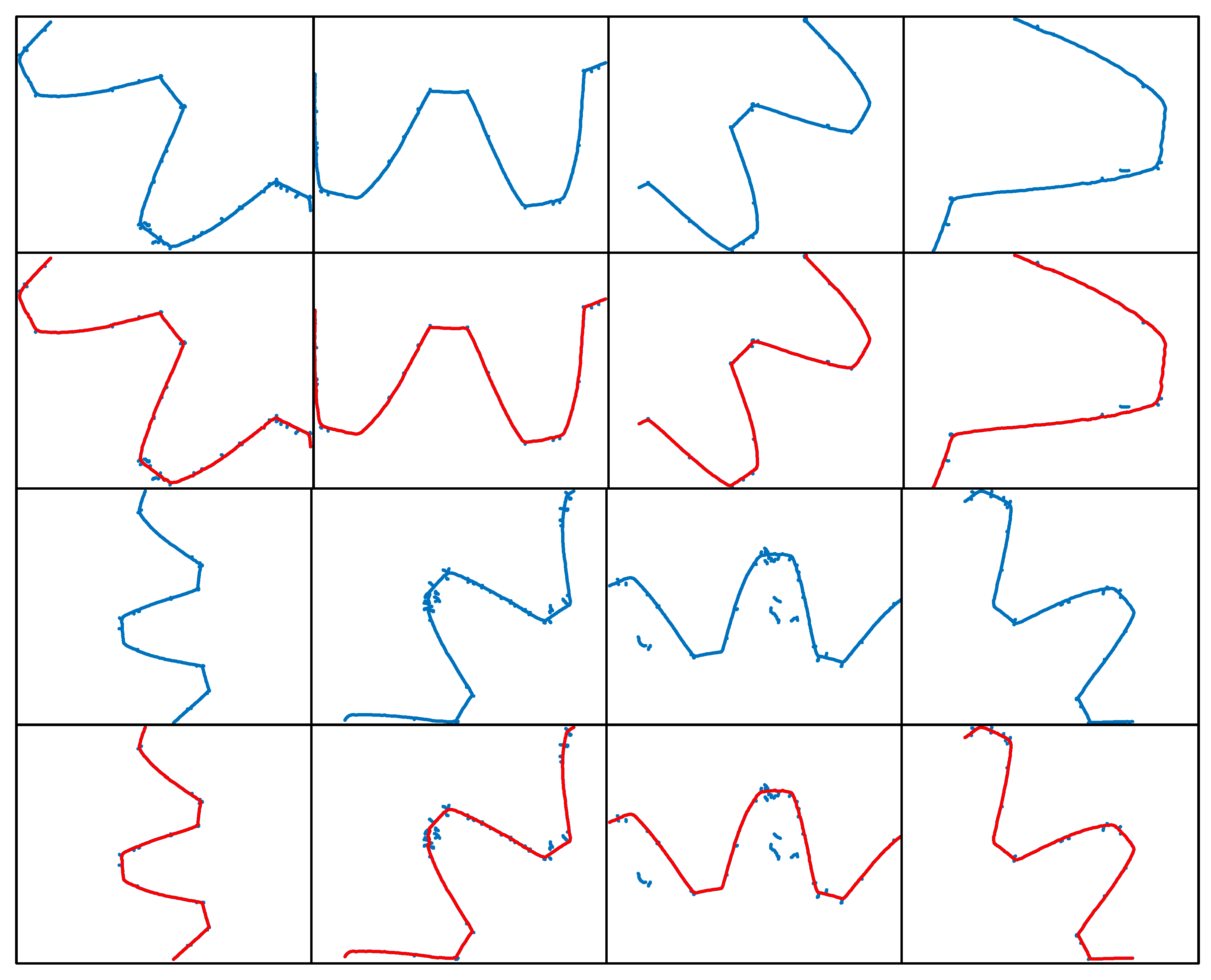
Figure 10.
Extraction results of the rectangular spline laser stripe centerline.
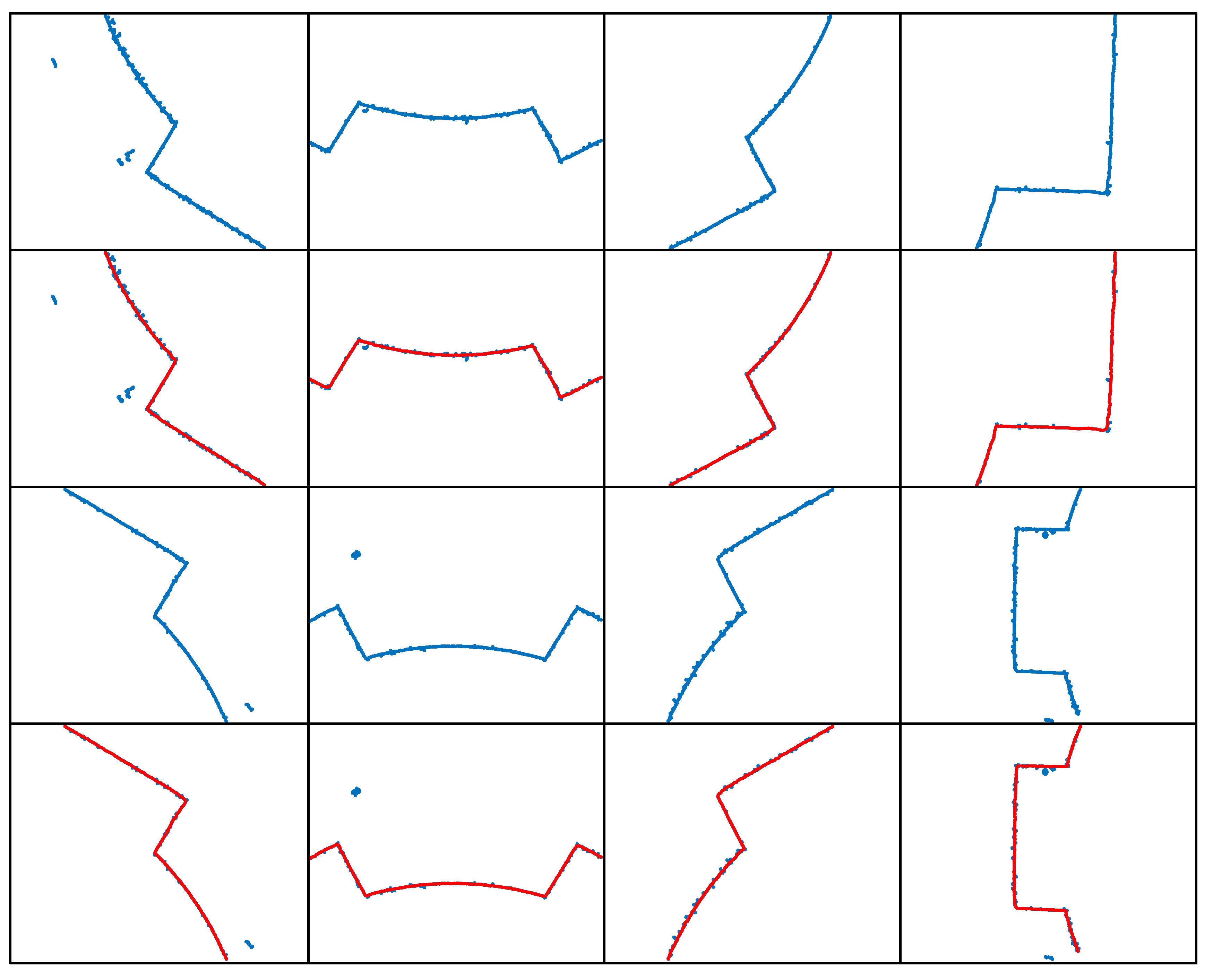
Figure 11.
Extraction results of the internal octagonal laser stripe centerline.
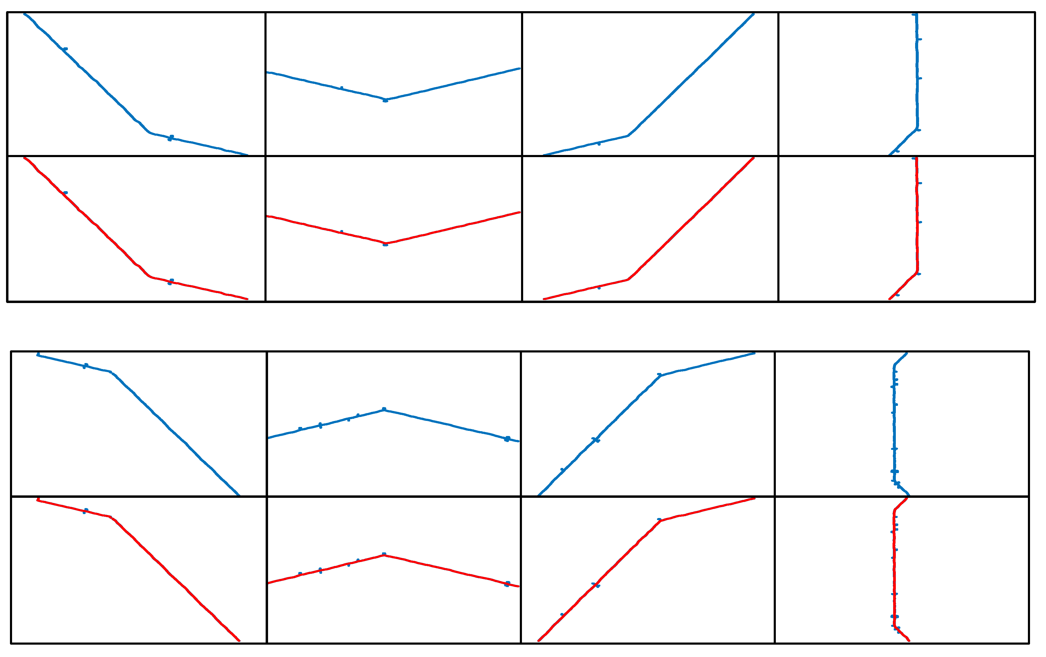
Figure 12.
Laser stripe centerline extraction results based on MST and DFS compared with manual extraction results.
Figure 12.
Laser stripe centerline extraction results based on MST and DFS compared with manual extraction results.
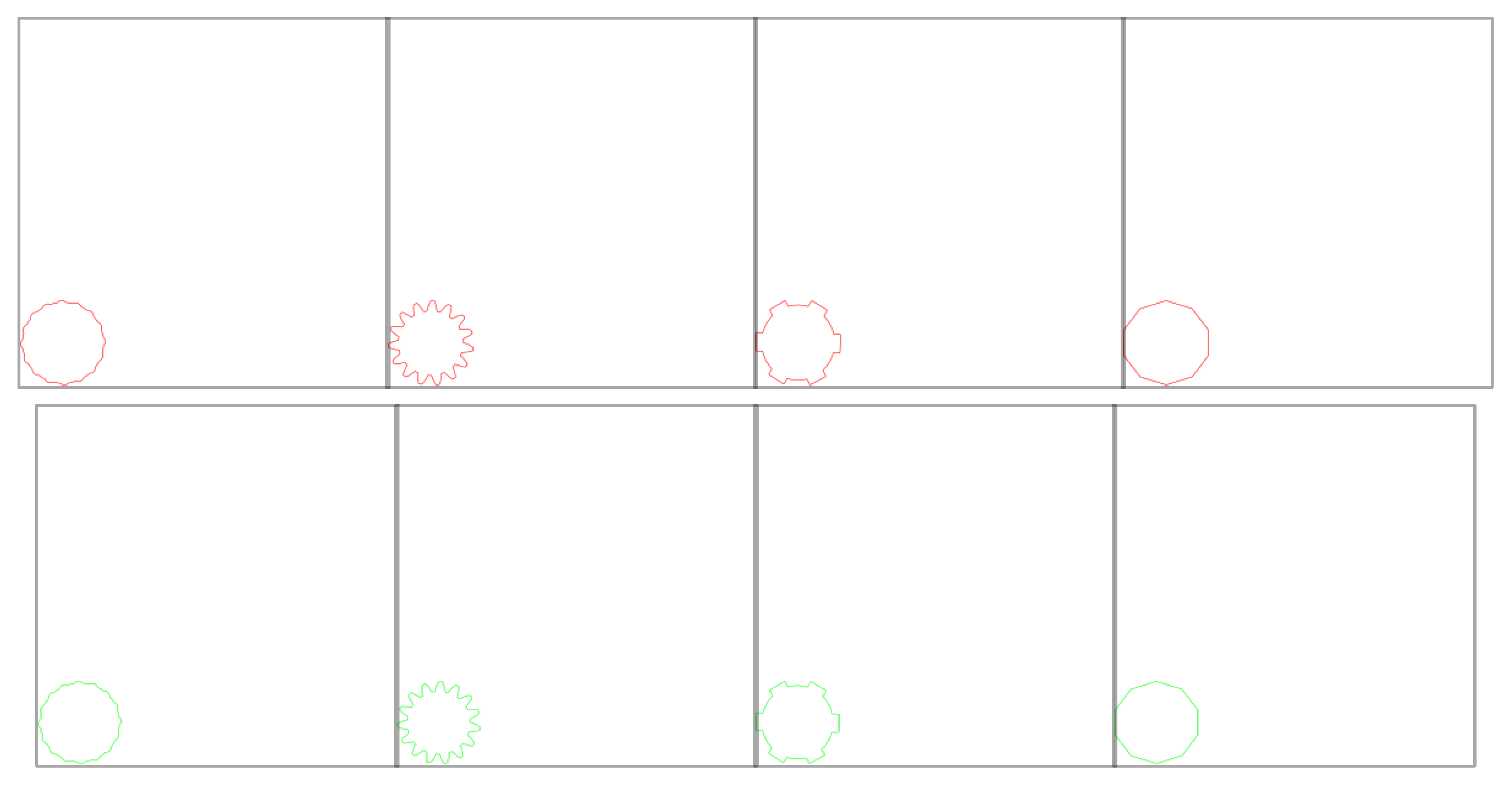

Table 1.
DSC and HD numerical table of different types of laser stripes.
| Laser Stripe | Petal-Shaped | Inner Gear. | Spline | Internal octagon |
|---|---|---|---|---|
| Hausdorff Distance | 3.3821 | 1.6414 | 2.0000 | 0.9653 |
| Dice Similarity Coefficient | 0.9986 | 0.9987 | 0.9953 | 0.9992 |
Disclaimer/Publisher’s Note: The statements, opinions and data contained in all publications are solely those of the individual author(s) and contributor(s) and not of MDPI and/or the editor(s). MDPI and/or the editor(s) disclaim responsibility for any injury to people or property resulting from any ideas, methods, instructions or products referred to in the content. |
© 2025 by the authors. Licensee MDPI, Basel, Switzerland. This article is an open access article distributed under the terms and conditions of the Creative Commons Attribution (CC BY) license (http://creativecommons.org/licenses/by/4.0/).
Copyright: This open access article is published under a Creative Commons CC BY 4.0 license, which permit the free download, distribution, and reuse, provided that the author and preprint are cited in any reuse.


