
Submitted:
02 January 2025
Posted:
03 January 2025
You are already at the latest version
Abstract
A seed discharger for peanut plot breeding was designed and its seed supply, seed carrying, seed discharge and seed clearing processes were analysed. Two single stroke cylinders were used for seed replacement and to avoid confusion between different varieties of seeds. The working performance of the seed discharger was simulated by CFD-DEM mothed. The simulation results showed that the seed section hole could adsorb the seeds stably, the adsorption force at the seed suction hole was about 0.02N, and the seed clearing time was 0.31s, when the rotation speed of the seed discharge cylinder was set to be 25r/min, the diameter of the seed suction hole was set to be 6mm, and the working negative pressure was set to be 5.5kPa. The developed seed discharger was installed on the test bench to carry out the central composite design experiment, and the test results were analysed and optimized by Design-Expert software. The optimal parameters of the seed discharger were obtained as follows: rotational speed of the seed cylinder is 24.38 r/min, the diameter of the seed suction hole is 5.73 mm, and the working negative pressure is -6.15 kPa. Finally, the seed discharger was tested in the field, and the result shown that the seed spacing pass rate was more than 90%, the multiple seeds rate was less than 6%, the seed missing rate was less than 4.5%, and the seed clearing rate was always 100%, which met the requirements of peanut plot seeding.
Keywords:
peanut
; seed discharger
; CFD-DEM
; plot breeding
1. Introduction
Peanut is an important oilseed crop in China [1,2,3], and the cultivation and promotion of excellent peanut varieties can increase peanut yields by at least 5% to 10%. The plot breeding trial is a process of selecting high quality varieties by sowing peanut seeds of different varieties into corresponding plots to compare growth traits [4,5,6]. The plot breeding trial is a necessary method for breeding new high-quality varieties [7,8,9] and is the most important part of the breeding process. During the process of plot trial, the quality of sowing is the key factor, which may affect the accuracy of the trial. Mechanised seeding can improve the accuracy of the plot trials, expand the scale of trials, shorten the cycle of breeding, and promote the breeding process of new peanut varieties [10].
The plot seed discharger is different from the seed discharger used in the field. The plot seed discharger needs to sow specific varieties of seeds in different plots, and must avoid mixing seeds between different plots during the working process, so as to improve the operation efficiency as much as possible under the premise of guaranteeing the sowing quality. The seed dischargers used in the field work with only one variety of seed and are more focused on working efficiently. When the seed discharger is used in the field for plot sowing, it is necessary to stop and change the seed between different plots, and this process is usually difficult to completely clear out seeds from the seed discharger, which not only reduces the work efficiency, but also leads to the confusion of different varieties of seeds, which makes the trial unscientific. The two main types of the seed discharger are mechanical and pneumatic. Pneumatic seed dischargers are more suitable for peanut seeds, which are easy to damage, due to less damage to the seed and adaptability to the seed size [11,12].
Many studies have been done on seed dischargers for plot breeding, but fewer seed dischargers are suitable for the peanut plot breeding [13]. They mainly solve the problem of seed mixing. For example, Ren Degang et al. [14] developed a seed discharger with a rotatable seed chamber, which is pulled by an one-way cylinder to clear the seed; Chang Xueliang et al. [15] developed a vertical disc-type air-suction peanut plot seed discharger by dividing the seed discharger into seed supply zone, seed discharge zone, and seed clearing zone using two one-way cylinders to avoid the mixing of seeds between different plots; Hao Jianjun et al. [16] improved the spoon clamp seed discharger and developed a single grain precision sowing unit for peanut plots; Liu Bing et al. [17] developed a roller-type plot seed discharger using the negative pressure to achieve the seed clearing rate of 100%. However, the internal airflow mechanism of the plot seed discharger has not been analysed in detail.
The CFD-DEM method is often used in the design process of seed dischargers, where a discrete elemental model of the seed is created by EDEM software, and the optimisation of the seed discharger structure is achieved by coupling seeds with the air flow field [18,19]. For example, Yu Yaxin et al. [20] developed a combined directional seed discharger for pumpkin seeds based on CFD-DEM method; Shang Zengzhong et al. [22] developed an air-suction soybean seed discharger based on CFD-DEM method and optimised the parameters of the seed discharge disc; Wang Guowei et al. [23] developed a high-speed precision seed discharger for soybean with auxiliary seed filling air suction based on the DEM-CFD method; Ding Li et al. [24,25] developed a maize air-suction seed discharger and optimized the structure of the seed disc based on CFD-DEM method.
In this paper, on the basis of the above research, a double-cylinder type seed discharger for peanut plot breeding was developed, in which the interior of the seed discharger is divided by two single-pass cylinders, and the supply and clearing of seeds in the seed chamber are realised by controlling the working status of seed supplying and seed clearing cylinders to avoid the mixing of different varieties. The seed suction holes, seed discharger rotational speed, and working negative pressure were determined by Fluent software, and the structure and working effect of the seed discharger were designed by CFD-DEM method.
2. Materials and Methods
2.1. Composition and Working Principle of the Seed Discharger
2.1.1. Composition of the Seed Discharger
The peanut plot seed discharger consists of seed discharge device, seed supply device, seed clearing device and support device, as shown in Figure 1(a). Seed supply device consists of seed supply tube, seed supply plate and seed supply cylinder (40mm stroke). The seed discharge device consists of end cover, seed discharge cylinder, hollow shaft, plug hole wheel and a chain wheel. The seed cleaning device consists of a seed clearing board, a seed clearing cylinder (70 mm stroke) and a sprocket.
As shown in Figure 1(b), the seed supply device is located above the seed discharge device for providing seeds, the seed clearing device is fixed under the support plate and connected to the seed chamber of the seed discharge device for clearing the seeds in the seed chamber, and the two sides of the seed discharge device are fixed by the support plate and mounted on the planter.
The seed discharge cylinder is the core component that affects the seed discharge performance, and the seed supply and seed clearing device are the key components that affect the non-mixing of seeds between the different plots.
2.1.2. Working Principle of the Seed Discharger
The working process of the seed discharger consists of four stages: seed supply, seed carrying, seed discharge and seed clearing. The seed supply cylinder is a two-position three-way cylinder with a stroke of 40mm, the seed clearing cylinder is a three-position two-way cylinder with a stroke of 70mm, and the seed supply and seed clearing cylinders are controlled by solenoid valves.
As shown in Figure 2(a), after the planter has finished sowing a plot, it clears the seed before moving on to the next plot. When the seed discharger in the process of seed clearing, the seed clearing plate is pulled by the seed clearing cylinder, and the remaining seeds in the seed chamber falls into the seed clearing box, under negative air pressure, to ensure that the seed is not mixed with the next variety.
As shown in Figure 2(b), when the seed discharger works, the peanut seeds are put in from the seed supply tube and fall on the seed supply plate connected to the end of the seed supply cylinder. And then, the solenoid valve controls the cylinder to switch the position of the seed supply plate to move under the action of pneumatic force, and the seeds fall from the seed supply plate into the seed chamber of the seed discharger to realise the supply of seeds. One end of the seed discharge shaft is connected to the air suction fan through a plastic tube, and the inner chamber of the seed discharge cylinder consists of a closed air chamber, which adsorbs the seeds by using the principle of negative air pressure. The sprocket of the seed discharger is connected to the ground wheel drive system and rotates as the planter moves forward and the seed discharger enters the seed carrying stage. Air enters the suction shaft through the seed suction holes into the interior of the air suction fan. Peanut seeds near the suction hole are adsorbed by the suction force and follow the seed discharge cylinder in a circular motion. When the seed enters the seed discharge zone, the suction force at the suction hole disappears due to the nelon wheel blocking the suction hole, and the peanut seed falls under the action of gravity.
2.2. Material Parameters of Peanut Seeds and Seed Discharger Materials
The sizes of peanut seeds are important for the design of seed discharger. In this paper, Luhua 11 peanut was selected. Three groups of peanut seeds were selected with 150 seeds each, and seed length L, seed width W, and seed thickness H were measured using vernier calipers with an accuracy of 0.01 mm, as shown in Figure 3(a). Measurement of modulus of elasticity, Poisson’s ratio and coefficient of static friction of peanut seeds by experimental apparatus, as shown in Figure 3.
The material of the seed discharger was selected as stainless steel. The material parameters of peanut seeds, stainless steel, and the contact parameters between seed and seed as well as between seed and seed discharger were measured, as shown in Table 1.
2.3. Design of Seed Supply and Clearing Devices
2.3.1. Principle of Operation of the Seed Supply and Clearing Device
Seed supply device and seed clearing device are respectively to achieve the seed supply and seed clearing process of the device and both devices do not interfere with each other, as shown in Figure 4. Seed supply cylinder and seed cleaning cylinder are the driving device of seed supply plate and seed clearing plate. The seed supply cylinder drags the seed supply plate to move under the action of the solenoid valve to realise the open and close of the seed supply tube. The seed clearing cylinder drags the seed clearing plate to realise the clearing of seeds in the seed chamber under the action of the solenoid valve.
The seed chamber of peanut seeds is an important part to ensure seed supply and improve the efficiency of seed adsorption. When the tilt angle of the seed clearing plate is 35°, the falling speed of the seed is slow, which can improve the possibility of the seed being adsorbed, and also ensure that the seed enter the seed clearing pipe smoothly. The 70mm stroke cylinder can ensure seeds enter the seed clearing tube instantly, and achieve 100% seed clearing rate. The seed clearing cylinder of the seed clearing device is connected to the suction tube, and the seed clearing tube with an inner diameter of 29 mm is selected according to the size of peanut seeds and the material of the tube. When the seed discharger clears the seed, the cylinder controls the seed clearing plate to unload the seed into the seed clearing box. And then, seeds well fell into the seed clearing box by the negative pressure.
The force of the seed in the seed clearing process was analysed as shown in Figure 4(I). As can be seen from Figure 4(I), the peanut seeds in the seed chamber slide along the seed clearing plate to the seed discharge cylinder under the action of the support force, gravity, and friction.
where, FN is the support force of the clearing plate on the seed, N; f is the friction force of the clearing plate on the seed, N; θ is the inclination angle of the clearing plate, °; m is the mass of the seed, kg; and g is the acceleration of gravity, N/kg.
2.3.2. Theoretical Analysis of the Seed Absorption Process
As shown in Figure 5, in the seed discharge stage, the seed firstly moves to the suction hole under the action of the airflow field, and then the seed will be stably adsorbed on the suction hole and follow the seed suction hole in a circular motion. For the peanut seeds on the clear plate to be successfully adsorbed onto the suction holes, the adsorption force on the seed at the suction hole needs to overcome the resistance generated by the seed population as well as the force of gravity. After the seed is adsorbed on the seed suction hole, the centrifugal force generated by the movement of the seed needs to be overcome additionally as the seed discharge cylinder moves in a circular motion.
When the peanut seeds are not in contact with the seed discharge cylinder, they are subjected to the action of adsorption force causing them to move towards the seed suction hole with acceleration, and the state of seed movement at this moment is shown in equation 2.
where, is the force of the seed by other seeds, N; F′ is the suction force on the seed produced by the negative pressure, N; FN is the support force on the seed by the seed discharger cylinder, N; G is the gravitational force of the peanut seed, N; f is the friction force on the seed by the discharger cylinder; f ’ is the friction force on the seed by other seeds; a’ is the acceleration of the seed produced by the combined force, m/s2; θ is the angle between the force of other seeds on the seed and the radius of rotation, °; μ is the angle of static friction between the seed and the seed discharger cylinder, (°); γ is the angle of static friction between the seeds, (°); α is the angle between the line of the seed and the rotating center of the seed discharger and the horizontal plane, (°).
The suction force of the seed suction hole is obtained from equation 2 as shown in equation 3.
According to Newton’s second law, a peanut seed will get acceleration when the adsorption force is sufficient to overcome other resistance. When the peanut seed moves up to the seed suction hole, it will be subjected to the support force and friction force of the seed discharge cylinder, and follow the seed discharge cylinder to do a stable circular motion under the action of the suction force. The state of the seed’s motion at this moment can be shown by equation 4.
where, μ is the static friction coefficient between the seed and the seed discharge cylinder; ω is the angular velocity of the seed discharge cylinder, rad/s; R is the radius of the seed discharge cylinder, m.
The suction force of the seed suction hole can be obtained from equation 4 as shown in equation 5.
Negative pressure at the seed suction hole needs to be determined according to the adsorption force of the peanut seed in the seed carrying process, and the adsorption force of the peanut is shown in equation 6. As shown in equation 6, the larger the diameter of the seed suction hole, the larger the contact area between the peanut seed and the seed-sucking hole, and the larger the adsorption force that the peanut seed is subjected to. The ideal plan is to make the contact surface between the seed and the suction hole as large as possible to reduce the magnitude of the negative pressure required and reduce power consumption.
where, Cd is the coefficient of damping force; ρ is the density of air, kg/m3; d is the diameter of the seed suction hole, m; v0 is the average speed of the airflow acting on the seed at the seed suction hole, m/s; A is the projected area of the seed in the direction of vertical movement, m2; ΔPN is the difference in internal and external pressures of the seed at the seed suction hole, Pa.
2.4. Design and Theoretical Analysis of Seed Discharge Device
2.4.1. Structural Design of the Seed Discharge Cylinder
The rotational speed of the seed discharge cylinder is an important factor in the sowing process. Increasing the rotational speed of the cylinder can increase the working efficiency of the planter. However, as the rotational speed of the cylinder increases, the linear velocity of the seed suction holes increases and the seed may be not adsorbed at the suction hole in time, which results in the seed missing. According to the requirements of the “Agricultural Machinery Design Manual”, the maximum linear velocity of the suction hole is not greater than 0.35 m/s, and the diameter of the seed discharge cylinder ranges from 140 to 260 mm. Considering the physical properties of the peanut seed, the structure of the seed discharger, the power consumption of the air fan and other factors, the final choice of the seed discharge cylinder diameter of 190 mm. At this time, the limit of the seed discharger rotational speed of 35 r/min. The relationship between rotational speed and linear velocity at the seed suction hole is shown in equation 7.
where, v is the linear velocity at the seed suction hole, m/s; R is the radius of the seed discharge cylinder, mm; n is the rotational speed of the seed discharge cylinder, r/min.
The structure of the seed-suction hole directly affects its ability to adsorb seeds. The current seed suction holes have straight holes, conical holes and sunken holes, among which straight holes have the largest airflow velocity and the best adsorption effect on seeds. According to the “Agricultural Machinery Design Manual” and the size of the seeds in Table 1, the diameter of the seed suction holes can be calculated according to equation 8 in the range of 5.03-7.85 mm.
where, d is the diameter of the seed suction hole, mm; b is the average width of the seed, mm.
The vacuum of the seed suction hole and the rotational speed of the seed discharge cylinder is the main factor affecting the working performance, the maximum value of the vacuum required by the seed suction hole can be calculated by equation (9).
where, Hcmax is the air-suction vacuum’s minimum, kPa; C is the center of gravity of the seed from the distance between the row of seed discs, cm; m is the mass of a seed, kg; v is the row of seed disc suction hole in the center of the linear speed, m/s; r is the row of seed disc suction hole at the radius of rotation, m; g is the acceleration of gravity, m/s2; λ is the seed of friction resistance composite coefficient, λ= (6~10) tanα, α is the natural angle of repose of the seed, degrees; K1 is the reliability coefficient of seed suction, take 1.8~2.0, the seed mass of thousands of grains is small, the shape of the near-spherical take a small value; K2 is the coefficient of the external conditions, take 1.8~2.0, the seed mass of thousands of grains is large take a large value; and d is the diameter of the hole of the seed suction, cm.
According to Equation 9, the maximum vacuum at the seed suction holes can be taken in the range of 5.88-7.85 kPa.
The number of seed suction holes is highly related to the seed absorption efficiency. With the increase of the number of seed suction holes on the seed discharge cylinder, the rotational speed of the seed discharge cylinder is reduced, the linear speed is also reduced, the seed is adsorbed in a longer time, and the seed absorption efficiency will be improved. Therefore, the number of seed suction holes should be better without affecting the seed absorption effect. However, when the number of seed suction holes increases to a certain extent, the distance between the seed suction holes decreases, and seed suction holes will interfere each other, affecting the stability of seed adsorption. The number of seed suction holes of the seed discharger can be calculated according to equation 10.
where, Δl1 is the arc length between the center of adjacent seed suction holes on the seed discharge cylinder, mm; lmax is the maximum size of the seed, mm; Z is the number of seed suction holes; D is the diameter of the seed discharge cylinder, mm; d is the diameter of the seed suction holes, mm; Δl is the shortest distance between the adjacent seed suction holes, mm.
The number of seed suction holes of the seed discharge cylinder is calculated to be 10 and evenly distributed on the circumference of the middle of the seed discharge cylinder.
2.4.2. Analysis of the Seed Carrying Process
The peanut seeds are adsorbed onto the seed discharger and will move in a circular motion with the seed discharger. At this stage, the peanut seed moves in a circular motion under the action of its gravity G, the adsorption force F generated by the seed suction hole, the normal support force FN and tangential friction ƒ generated by the seed discharger on the peanut seed, and will generate the centrifugal force Fr. Set the angle between the peanut seed and the seed discharger in the horizontal direction as β, and establish the mechanical models in the normal direction and tangential direction according to the range of the variation of the angle, respectively, as shown in Figure 6.
(1) When 0°<β<90°, the forces on the peanut seed in the normal and tangential directions are shown in Figure 6(a), and the balance equations are established in the normal and tangential directions, respectively, as shown in equation 11.
According to equations 5, 6, and 11, the adsorption force to be provided at the seed suction hole was calculated as shown in equation 12.
When 0°<β<90°, the minimum adsorption of the peanut seed decreases with increasing β. The extreme value of adsorption force in this range is shown in equation 13.
(2) When 90°<β<180°, the forces on the peanut seed in the normal and tangential directions are shown in Figure 6(b), and the balance equations are established in the normal and tangential directions, respectively, as shown in equation 14.
According to equations 5, 6, and 14, the adsorption force to be provided at the seed suction hole was calculated as shown in equation 15.
When 90°<β<180°, the minimum adsorption of the peanut seed increases with increasing β. The extreme value of adsorption force in this range is shown in equation 16.
(3) When 180°<β<270°, the forces on the peanut seed in the normal and tangential directions are shown in Figure 6(c), and the balance equations are established in the normal and tangential directions, respectively, as shown in equation 17.
According to equations 5, 6, and 17, the adsorption force to be provided at the seed suction hole was calculated as shown in equation 18.
When 180°<β<270°, the minimum adsorption of the peanut seed decreases with increasing β. The extreme value of adsorption force in this range is shown in equation 19.
(4) When 270°<β<297°, the forces on the peanut seed in the normal and tangential directions are shown in Figure 6(d), and the balance equations are established in the normal and tangential directions, respectively, as shown in equation 20.
According to equations 5, 6, and 20, the adsorption force to be provided at the seed suction hole was calculated as shown in equation 21.
When 270°<β<297°, the minimum adsorption of the peanut seed decreases with increasing β. The extreme value of adsorption force in this range is shown in equation 22.
According to the mechanical analysis of the seed in different seed-carrying processes above, the adsorption force on the peanut seed decreases with the increase of β and then increases and then decreases. The peanut seed is least likely to adsorb the seed when the extreme value of the adsorption force is 180°+μ. The size of the negative pressure in the seed chamber can be selected based on the result.
2.5. Design of the Seed Discharge Device
The seed discharge process involves cutting off the airflow at the seed suction hole so that the seed loses its absorption force. Then, the seeds are disengaged from the seed suction hole by gravity. As shown in Figure 7(a), a wheel made of nylon material is designed to be installed inside the air suction shaft to plug the seed suction holes. The airflow is cut off by plugging the seed suction hole through the surface of the nylon wheel, as shown in Figure 7(b). The outer diameter of the wheel is 40 mm and the thickness of the wheel is 12 mm, which provides air pressure isolation for seed discharge. As shown in Figure 7(c), the seed loses the adsorption force, and then makes uniform linear motion in the horizontal direction, and free-fall motion in the direction of gravity.
In order to keep the peanut seeds as immobile as possible in the horizontal direction, the mounting angle of the nylon wheel needs to be designed as shown in Figure 6(c). Neglecting the effect of the air resistance, the equation of motion of the seed as it falls is shown in equation 23.
Where, V is the horizontal velocity of the seed, m/s; V1 is the linear velocity of the seed suction hole, m/s; V0 is the working speed of the planter, m/s; R is the radius of the seed discharge cylinder, mm; n is the rotational velocity of the seed discharge cylinder, r/min; ω is the angular velocity of the seed discharge cylinder, rad/s.
According to the equation 23, it can be seen that the rotational velocity of the seed discharger affects the movement of the seed in the seed falling stage. By analysing the seed falling stage, it is obtained that when the angle θ = 27 ° between the nylon wheel and the vertical direction, the peanut seeds can maximally move near zero speed in the horizontal direction. The actual seed drop distance X of peanut seeds can be obtained by further calculation.
3. Simulation Modeling and Analysis
3.1. Determination of Key Structural Parameters
3.1.1. Simulation Model Building and Parameter Setting
The air chamber inside seed suction holes and the suction shaft were modelled by SOLIDWORKS software, respectively, and the model was exported to ICEM-CFD for meshing. As shown in Figure 8, define seed suction holes and the suction shaft as fluid. Select the contact surface of seed suction holes and the suction shaft as the interface, set the outer surface of the seed suction hole as the pressure inlet, and set one end of the suction shaft as the pressure outlet, and output the mesh file as a cas file after all the setups are completed.
3.1.2. Simulation of Fluid Field with Different Seed Suction Hole Diameters
According to the research described in the previous section, three types of seed suction holes with diameters of 5.5, 6 and 6.5 mm were selected. The outlet pressure was set to -5.5 kPa, and the rotational speed of the seed discharge cylinder was 25 r/min. As shown in Figure 9, when the diameter of the seed suction hole is 6 mm, the airflow velocity round the seed suction hole is higher than that the other sizes of seed suction holes, indicating that the 6 mm diameter seed suction hole is easier to adsorb the seed.
The seed discharger with the diameter of 6 mm in the seed suction hole was sliced in cross-section, as shown in Figure 10. The airflow velocity changed in the inlet and outlet ends of the seed suction hole, and diffused in the tail of the flow velocity at the end connected with the air chamber. Pressure changes were mainly concentrated at the seed suction hole, and the air pressure inside the air chamber was relatively stable. The stable air pressure provided at the seed suction hole ensures that a stable adsorption force is generated during seed adsorption, which is easier for seed adsorption.
3.1.3. Simulation of Flow Field at Different Rotational Speeds of the Seed Discharge Cylinder
According to the previous analysis, the rotational speed of the seed discharge cylinder is one of the important parameters affecting the sowing quality. In order to observe the field of fluid inside the seed discharger with different rotational speeds, three kinds of rotational speeds of the seed discharger, 20, 25 and 30 r/min, were selected for analysis, and the negative air pressure of 5.5 kPa was set, and the diameter of the seed suction hole was 6 mm, as shown in Figure 11. The pressure maps of the cross-section of the airflow field at different rotational speeds are basically the same, and the internal air chamber pressure is smooth.
As shown in Figure 12, the pressure and velocity of the fluid in different sections of the seed discharger are monitored in the CFD-POST software. As a result, the seed discharger rotational speed has almost no effect on the internal air chamber pressure. Therefore, the seed discharger rotational speed of 25 r/min was selected.
3.1.4. Simulation of the Flow Field with Different Negative Pressures
In order to observe the flow field within the seed discharger at various negative pressures, negative pressure values of -4, -5.5, and -7 kPa were selected for analysis. The rotational speed of the seed discharge cylinder was set to 25 r/min, and the diameter of the seed suction hole was 6 mm, as shown in Figure 13. The cross-section and longitudinal section of the airflow field were sliced in CFD-POST. From the cross-section slices, it can be observed that pressure variations occur near the seed suction hole of the seed discharger, while the pressure inside the air chamber remains essentially unchanged.
As known from Figure 14, from the longitudinal section slices, it can be observed that the negative air pressure at the pressure outlet appeared to decay, while the pressure inside the air chamber did not change significantly. Pressure changes occurred at each seed suction hole, the pressure remained relatively smooth, and the pressure between the seed suction holes did not interfere with each other. The greater the pressure difference between the seed suction holes, the better the adsorption of seeds, but the fan power increases, resulting in increased capacity consumption. Comprehensive consideration, set the pressure outlet as -5.5 kPa.
3.2. Coupling Simulation Based on CFD-DEM Method
3.2.1. Parameter Setting of the Simulation Model
Set the rotational speed of the seed discharge cylinder in EDEM to be 25 r/min, and set the same rotational speed in the corresponding flow field region in FLUENT. The time step of EDEM is set to 1×10⁻⁷ s, the time step of FLUENT is set to 1×10⁻⁵s, and the number of simulation steps is set to 105, i.e., the simulation time is 1 s. The inlet pressure is set to 0 kPa and the outlet pressure is set to -5.5 kPa in FLUENT. The maximum number of iterations in each time step of FLUENT is set to 50. The coupled drag force model is set to Ergun and Wen&Yu.
The API (secondary development programme for particle fields) was used to replace the particles and obtain a discrete model of the peanut seed. Since the minimum grid cell volume of the airflow field is 7.03×10⁻¹⁰m3, small particles with a radius of 0.55 mm are selected. The volume of the particles is 6.96×10⁻¹⁰m3, and the total volume of the peanut seed is 9×10⁻⁷m3. The number of particles to be filled was calculated according to equation 25. The filling volume coefficient α was chosen to be 0.6 and the number of filled particles was calculated to be 736.
where, α is the filling volume coefficient; N is the number of filling particles; VT is the volume of the seed, m3; and VS is the volume of the filling particles, m3.
Import the simplified model of the seed discharge cylinder into EDEM and create a particle factory. Set the number of seeds to be 25, and start particle replacement from 0.13 s. The replacement particles were output by EDEM Simulation Deck and coupled from 0 s. Fifteen seeds were selected as detect points as shown in Figure 15.
3.2.2. Simulation of Coupling and Results of the Seed Discharging Process
The particles are subjected to gravity, airflow field forces, and the contact forces between the seed and seed discharger during the simulation.
The forces acting on the particles in the airflow field are output in the form of coupling force (Coupling Force). The velocity, displacement, kinetic energy and coupling force of the seed during the simulation can be obtained by marking a particular particle. The coupling simulation process is shown in Figure 16.
The particles were marked in Setup Selections of EDEM to obtain the velocity and coupling force of the seed in the simulation process. As shown in Figure 17, the velocity and coupling force of the seeds at each seed suction hole are more evenly balanced during the coupling process, indicating that the peanut seeds can achieve stable adsorption force under the negative pressure of -5.5 kPa.
3.2.3. The Coupled Process of the Seed Clearing and Simulation Results
The air suction seed discharger for plot seeding needs to have a seed clearing function in order to prevent the seed of different varieties from being mixed, and to clear away the remaining seed in time before entering the next plot. The simplified model of the seed clearing chamber was imported into EDEM, and the coupling simulation was performed as described in the previous coupling method. Set the negative pressure at the outlet to be -4 kPa and use the API to replace the particles. As shown in Figure 18, the seed clearing device can achieve 100% seed clearing.
According to the working speed of the plot breeding planter is 1 m/s and the distance between the plots is 1 m. Mark the last particles in Figure 18 and export the displacement curve of the particle. As shown in Figure 18, the seeds in the seed clearing chamber can be completely removed in 0.31 s. The seed displacement curve is shown in Figure 19. The seed clearing time is less than 1 s, indicating that the seeds of the previous variety can be removed before moving to the next plot.
4. Performance Testing of the Seed Discharger
4.1. Preparation and Method of Test
The seed discharger was installed on the test bench for performance testing, as shown in Figure 20. The seed discharger is mounted at one end of the test bench and is driven by a drive motor for seeding. Seeds were discharged and fell on the conveyor belt and passed through the measuring device to obtain the sowing performance.
The test bench is JPS-12 computer vision seed discharger test bench. The test process was repeated three times, and 250 seeds were measured each time. The test indicators were calculated in accordance with GB/T 6973-2005 “Test Methods for Single Seed ‘Precision’ Planter”, and the calculation method is shown in equation 26.
where, n1 is the number of holes with qualified seed spacing; n2 is the number of holes with multiple seeds; n3 is the number of holes without seeds; and N is the total number of holes that are measured.
According to the JB/T51017-1999 “medium-tillage crop precision planter product quality grading” and JB/T10293-2013 “single grain ‘precision’ planter technical conditions” to get the sowing index evaluation standard. The seeding pass rate needs to be greater than 80%, the reseeding rate needs to be less than 15%, and the leakage rate needs to be less than 8%, as shown in Table 2.
4.2. Test Program and Results
The seed discharger rotational velocity, working negative pressure, and seed suction hole diameter were selected as the test factors, and the seed spacing pass rate, multiple seeds rate, and seed missing rate were selected as the test indicators to carry out the central composite experimental design. The test results were analysed by Design-Expert 13 software. Five levels were taken for each test factor as shown in Table 3. The total number of test programs was 20, and each test data was repeated three times to get the average value, and the test results are shown in Table 4.
4.3. Analysis of the Test Results
4.3.1. Regression Modelling of Test Indicators
The quadratic regression models for seed spacing pass rate, multiple seeds rate, and seed missing rate were developed by Design-Expert 13, respectively. As shown in Table 5, according to the correction coefficient Adjusted R2 of the regression models of the three indicators, it can be seen that the three models can explain 96.85%, 93.75%, and 95.44% of the corresponding changes respectively. Adeq Precision measures the signal to noise ratio. A ratio greater than 4 is desirable. As can be seen in Table 5, the Adeq Precision values of the three indicators are all bigger than 4, which indicated all models can be used to navigate their design space. As shown in Tables 6, 7, and 8, according to the ANOVA table for the indicators, the P-value < 0.05, which is shown as significant, and P-value < 0.01, which is shown as highly significant.
The P-value of Lack of Fit is 0.2653, which is shown to be insignificant (P > 0.05), indicating that the regression equation is simulated relatively well and the model is accepted. The quadratic regression model for the seed spacing pass rate was obtained as shown in equation 27.

Table 7.
Anova analysis of multiple seeds rate.
| Source | Sum of Squares | df | F-value | P-value |
|---|---|---|---|---|
| Model | 147.60 | 9 | 16.67 | < 0.0001 |
| X1-Speed | 62.67 | 1 | 63.68 | < 0.0001 |
| X2-Suction hole diameter | 0.9016 | 1 | 0.9162 | 0.3610 |
| X3-Negative pressure | 40.44 | 1 | 41.09 | < 0.0001 |
| X1X2 | 3.78 | 1 | 3.84 | 0.0784 |
| X1X3 | 13.78 | 1 | 14.00 | 0.0038 |
| X2X3 | 0.1012 | 1 | 0.1029 | 0.7550 |
| X12 | 22.43 | 1 | 22.80 | 0.0008 |
| X22 | 5.39 | 1 | 5.47 | 0.0414 |
| X32 | 0.7128 | 1 | 0.7243 | 0.4146 |
| Residual | 9.84 | 10 | ||
| Lack of Fit | 4.67 | 5 | 0.9022 | 0.5436 |
| Pure Error | 5.17 | 5 | ||
| Cor Total | 157.45 | 19 |
The P-value of Lack of Fit is 0.5436, which is shown to be insignificant (P > 0.05), indicating that the regression equation is simulated relatively well and the model is accepted. The quadratic regression model for the multiple seeds rate was obtained as shown in equation 28.
The P-value of Lack of Fit is 0.0522, which is shown to be insignificant (P > 0.05), indicating that the regression equation is simulated relatively well and the model is accepted. The quadratic regression model for the seed missing rate was obtained as shown in equation 29.
Table 8.
Anova analysis of seed missing rate.
| Source | Sum of Squares | df | F-value | P-value |
|---|---|---|---|---|
| Model | 121.90 | 9 | 23.25 | < 0.0001 |
| X1-Speed | 8.91 | 1 | 15.30 | 0.0029 |
| X2-Suction hole diameter | 10.65 | 1 | 18.28 | 0.0016 |
| X3-Negative pressure | 14.81 | 1 | 25.43 | 0.0005 |
| X1X2 | 1.53 | 1 | 2.63 | 0.1360 |
| X1X3 | 5.95 | 1 | 10.22 | 0.0096 |
| X2X3 | 0.7813 | 1 | 1.34 | 0.2738 |
| X12 | 45.98 | 1 | 78.93 | < 0.0001 |
| X22 | 21.47 | 1 | 36.85 | 0.0001 |
| X32 | 26.73 | 1 | 45.89 | < 0.0001 |
| Residual | 5.83 | 10 | ||
| Lack of Fit | 5.30 | 5 | 10.03 | 0.0522 |
| Pure Error | 0.5283 | 5 | ||
| Cor Total | 121.90 | 9 | 23.25 | < 0.0001 |
4.3.2. Analysis of Response Surfaces
The response surfaces of the test factors on the seed spacing pass rate, the multiple seeds rate and the seed missing rate are shown in Figure 22.
The response surfaces of the seed spacing pass rate are shown in Figure 22 (a), (b), and (c). From the figure, it can be seen that the seed spacing pass rate can reach the maximum value when the speed of seed discharger is between 20 and 30 r/min, the diameter of seed suction hole is between 5 and 7 mm, and the working pressure is between 3 and 8 kPa. From the response surface, it can be seen that the effects of the three factors on the seed spacing pass rate can be ranked from largest to smallest: Speed>Suction hole diameter>Negative pressure.
The response surfaces of the multiple seeds rate are shown in Figure 22 (d), I, and (f). From the figure, it can be seen that the multiple seeds rate can reach the minimum value when the speed of seed discharger is between 20 and 30 r/min, the diameter of seed suction hole is between 5 and 7 mm, and the working pressure is between 3 and 8 kPa. From the response surface, it can be seen that the effects of the three factors on the multiple seeds rate can be ranked from largest to smallest: Speed>Negative pressure>Suction hole diameter.
The response surfaces of the seed missing rate are shown in Figure 22 (h), (i), and (j). From the figure, it can be seen that the seed missing rate can reach the minimum value when the speed of seed discharger is between 20 and 30 r/min, the diameter of seed suction hole is between 5 and 7 mm, and the working pressure is between 3 and 8 kPa. From the response surface, it can be seen that the effects of the three factors on the seed missing pass rate can be ranked from largest to smallest: Negative pressure>Suction hole diameter>Speed.
4.3.3. Optimum Working Parameters
Taking the seed discharger speed, working negative pressure, and the diameter of the seed suction hole as the influencing factors, and take the maximum value of the seed spacing pass rate as the objective function as shown in equation 30.
The best optimisation results were obtained by using Design-Expert 13: seed discharger rotational velocity was 24.38 r/min, seed suction hole diameter was 5.73 mm, and working pressure was -6.15 kPa. At this time, the performance indexes of the seed discharger were: the seed spacing pass rate was 93.60%, the multiple seeds rate was 3.35%, and the seed missing rate was 3.12%.
4.3.4. Field Trials
In June 2024, the seed discharger was mounted on the planter to test the effectiveness of its sowing process in the field. The total area of the test field was 12 m2, the row length was 5 m, the row spacing was 0.6 m, and the spacing between plots was 1 m. The planter was attached to the rear of a John Deere Skytractor JDT720 tractor, as shown in Figure23, and the planter was operated at the working speed of 3.6 km/h.
The negative pressure was set to be -6 kPa, the rotational velocity of the seed discharger was 25 r/min, and the diameter of the seed suction hole was 6 mm. The test results were calculated according to GB/T 6973-2005 Test Methods for Single-Grain (Precision) Planters. The test was divided into 3 groups, and each group was repeated 5 times, 250 seeds were measured each time, and the average value was taken as the test result.
The test results are shown in Table 9, the seed discharger’s sowing process is good, the seed spacing pass rate is more than 90%, the multiple seeds rate is less than 6%, the seed missing rate is less than 4.5%, and the seed clearing rate is 100%, which meets the sowing requirements.
Comparing the results of the field test and the test bench, the field test, due to the actual working environment, seed variability and other factors, resulting in the actual seed spacing pass rate is lower than the test result of the test bench. Due to unfavourable effects such as insufficient absorption of the seed suction hole during the actual sowing process leads to the lack of seed adsorption, resulting in an increase in the seed missing rate.
5. Conclusion
A seed discharger for peanut plot breeding was designed and its seed supply, seed carrying, seed discharging and seed clearing processes were analysed theoretically.
(1) Two single stroke cylinders were used for seed replacement and to avoid confusion between different varieties of seeds. The seed supply process is controlled by a seed supply cylinder with a stroke of 40 mm and the seed clearing process is controlled by a seed clearing cylinder with a stroke of 70 mm. The installation angle of the plugging wheel was designed to be 27° and the inclination angle of the seed clearing plate was designed to be 35°. The diameter of the seed discharge cylinder was designed to be 190mm, and the number of seed suction holes was designed to be 10.
(2) The flow field inside the seed discharger was analysed by Fluent software. The rotation speed of the seed discharge cylinder was designed to be 25r/min, the diameter of the seed suction hole was designed to be 6mm, and the working negative pressure was 5.5kPa. The simulation results of CFD-DEM mothed shown that the seed discharger could adsorb the seeds stably, the adsorption force at the seed suction hole was about 0.02N, and the seed clearing time was 0.31s.
(3) The developed seed discharger was installed on the test bench to carry out the central composite design experiment, and the test results were analysed and optimized with the help of Design-Expert 13 software. The optimal parameters of the seed discharger were obtained as follows: rotational speed of the seed cylinder is 24.38 r/min, the diameter of the seed suction hole is 5.73 mm, and the working negative pressure is -6.15 kPa. Finally, the seed discharger was tested in the field, and the results showed that the seed spacing pass rate was bigger than 90%, the multiple seeds rate was less than 6%, the seed missing rate was less than 4.5%, and the seed clearing rate reached 100%, which meets the requirements of peanut plot breeding.
Author Contributions
Conceptualization, D.R. and X.C.; methodology, X.C.; software, B.L.; validation, D.R., Y.Y. and Z.G.; formal analysis, Y.Y.; investigation, M.L.; resources, B.L.; data curation, M.L.; writing—original draft preparation, X.C.; writing—review and editing, D.R.; visualization, D.W.; supervision, Z.G.; project administration, D.W.; funding acquisition, D.W.
Funding
This research was funded by Key Technologies Research and Development Program (2022YFD2300100) and Key Technology Research and Development Program of Shandong Province (2024LZGC004).
Institutional Review Board Statement
Not applicable.
Data Availability Statement
The original contributions presented in the study are included in the article material, further inquiries can be directed to the corresponding authors.
Conflicts of Interest
The authors declare no conflicts of interest.
References
- Wang, Z.H.; Zhang, Y. Correlation and variability analysis of yield and quality related traits in different peanut varieties across various ecological zones of China. Oil Crop Science 2023, 8, 236–242. [Google Scholar] [CrossRef]
- Zhou, X.J.; Ren, X.P. Safe conservation and utilization of peanut germplasm resources in the Oil Crops Middle-term Genebank of China. Oil Crop Science 2022, 7, 9–13. [Google Scholar] [CrossRef]
- Zhao, S.C.; Lü, J.L. Peanut yield, nutrient uptake and nutrient requirements in different regions of China. Journal of Integrative Agriculture 2021, 20, 2502–2511. [Google Scholar] [CrossRef]
- Ricardo, J.H.; Willians, C.C. Row spacing and growth habit in peanut crops: Effects on seed yield determination across environments. Field Crops Research 2022, 275, 108363. [Google Scholar] [CrossRef]
- Zhao, J.H.; Lai, H.J. Effects of paclobutrazol application on plant architecture, lodging resistance, photosynthetic characteristics, and peanut yield at different single-seed precise sowing densities. The Crop Journal 2022, 11, 301–310. [Google Scholar] [CrossRef]
- Zhang, J.L.; Geng, Y. Research progress on the mechanism of improving peanut yield by single-seed precision sowing. Journal of Integrative Agriculture 2020, 19, 1919–1927. [Google Scholar] [CrossRef]
- Qiu, Y.J.; Li, G.Q. Research Hotspots and Trends of Groundnut (Arachis hypogaea L.) Breeding and Cultivation Based on Bibliometric Analysis. Journal of Peanut Science 2024, 53, 88–104. [Google Scholar] [CrossRef]
- Zhang, Z.Z.; Wang, C.H. Evolution analysis of main traits of registered peanut varieties in China from 2020 to 2023. Chinese Journal of Oil Crop Sciences 2024, 46, 687–696. [Google Scholar] [CrossRef]
- Liao, J.H.; Cong, J.L. Research progress of high-oleic acid peanut in China. Cereals & Oils 2023, 36, 5–8, https://kns.cnki.net/kcms2/article/abstract?v=UbUZFcLhzIJxkl86L47nLMTqR8SPshHb8cVHjhdQfImHcyFF1HzpHSjP5DuN-IX9EG0lrZpQR0eRgAT1ooI47NWsF5osG6Ouxx_gDFPw2r_S5_ytIRP2scNXENlUawgh9H7KJnCtZtPAcJ1Uk7rx8EtJh-9CpPsxo-kE7FufQnRaPr2WfB0pe6JedKsvOW&uniplatform=NZKPT&language=CHS.. [Google Scholar]
- Bruno, R.A.M.; Tulio, M.M. Advancements in peanut mechanization: Implications for sustainable agriculture. Agricultural Systems 2024, 215, 103868. [Google Scholar] [CrossRef]
- Çiftçi, S.; Suna, G. Functional components of peanuts (Arachis Hypogaea L.) and health benefits: A review. Future Foods 2022, 5, 100140. [Google Scholar] [CrossRef]
- Qi, B.B.; Cong, J.L. Experimental study on the effect of soaking treatment on peanut seed damage. Journal of Shihezi University (Natural Science) 2020, 38, 146–154. [Google Scholar] [CrossRef]
- Shang, S.Q.; Wu, C.D. Research Status and Prospect of Plot-sowing Equipment and Technology. Transactions of the Chinese Society for Agricultural Machinery 2021, 52, 1–20. [Google Scholar] [CrossRef]
- Ren, D.G.; Wang, D.W. Design and Experiment of Air Suction Seed Metering Device for Alfalfa Plot Breeding. Journal of Agricultural MechanizationResearch 2025, 47, 39–45. [Google Scholar] [CrossRef]
- Chang, X.L.; Shang, S.Q. Design and Test of Precision Planter for Peanut Community Breeding. Journal of Agricultural MechanizationResearch 2025, 7, 1–6. [Google Scholar] [CrossRef]
- Hao, J.J.; Qin, J.H. Design and experiments of a precision sowing unit with the spoon clip for single peanut seed planting in plot. Transactions of the Chinese Society of Agricultural Engineering 2023, 39, 33–41. [Google Scholar] [CrossRef]
- Liu, B.; Wang, D.W. Simulation and Experiment of Peanut Air Suction Seed Metering Device Based on DEM-CFD Coupling Method. Journal of Agricultural MechanizationResearch 2022, 44, 166–172. [Google Scholar] [CrossRef]
- Yu, Y.X.; Wang, Y. Design and Test of Combined Pumpkin Seed Attitude-constrained Directional Seed Metering Device. Transactions of the Chinese Society for Agricultural Machinery 2025, 55, 121–132. [Google Scholar] [CrossRef]
- Wang, W.W.; Song, L.Z. Design and Experiment of Air-suction Double-row Staggered Precision Seed Metering Device for Maize Dense Planting. Transactions of the Chinese Society for Agricultural Machinery 2024, 55, 53–63. [Google Scholar] [CrossRef]
- Shang, Z.Q.; Zhang, K.F. Simulation optimization of seed plate of air suction soybean seed-metering device based on DEM-CFD coupling. Journal of Chinese Agricultural Mechanization 2023, 44, 1–8. [Google Scholar] [CrossRef]
- Wang, G.W.; Xia, X.M. Design and experiment of soybean high⁃speed precision vacuum seed metering with auxiliary filling structure based on DEM⁃CFD. Journal of Jilin University (Engineering and Technology Edition) 2022, 52, 1208–1221. [Google Scholar] [CrossRef]
- Ding, L.; Yang, L. Design and Experiment of Seed Plate of Corn Air Suction Seed Metering Device Based on DEM-CFD. Transactions of the Chinese Society for Agricultural Machinery 2019, 50, 50–60. [Google Scholar] [CrossRef]
- Ding, L.; Yang, L. Simulation and Experiment of Corn Air Suction Seed Metering Device Based on DEM-CFD Coupling Method. Transactions of the Chinese Society for Agricultural Machinery 2018, 49, 48–57. [Google Scholar] [CrossRef]
Figure 1.
(a) Exploded view of the seed discharger; (b) Assembly diagram of the seed discharger. 1. Left support plate 2. Left end cover 3. Seed clearing tube 4. Seed clearing device support plate 5. Bearing 6. Air suction seed discharge tube 7. Seed discharge cylinder 8. Nylon wheel 9. Right seal 10. Air suction tube 11. Sprocket 12. Right support plate 13. Seed supply cylinder 14. Seed supply tube 15. Seed clearing cylinder 16. Seed clearing board 17. Lift seal 18. Screw.
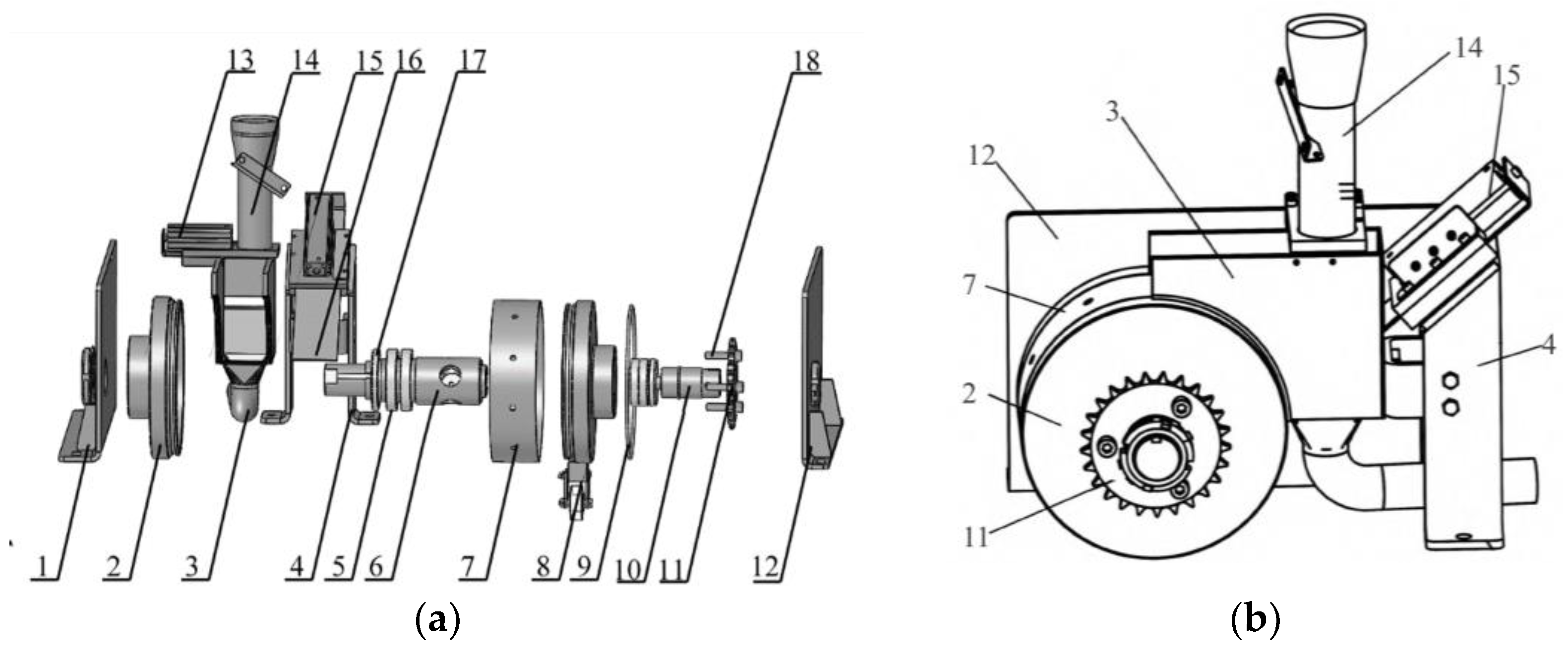
Figure 2.
(a) Schematic diagram of the plot breeding trial; (b) Work principle of the seed discharger.
Figure 2.
(a) Schematic diagram of the plot breeding trial; (b) Work principle of the seed discharger.
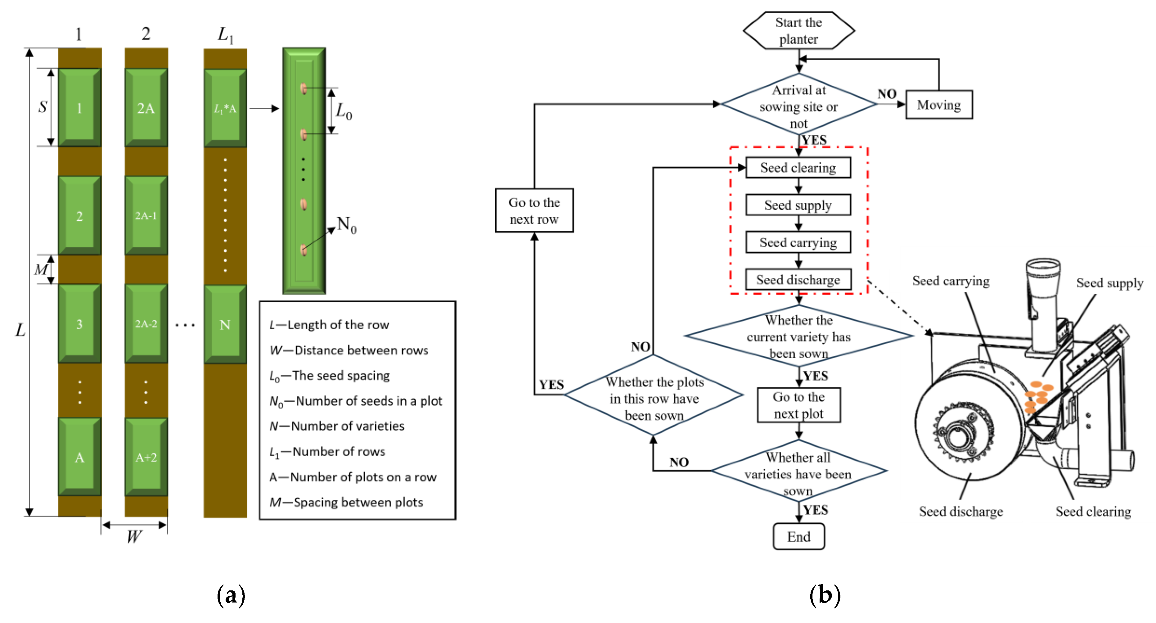
Figure 3.
(a) Three-dimensional size of the peanut seed; (b) Measurement of material parameters.
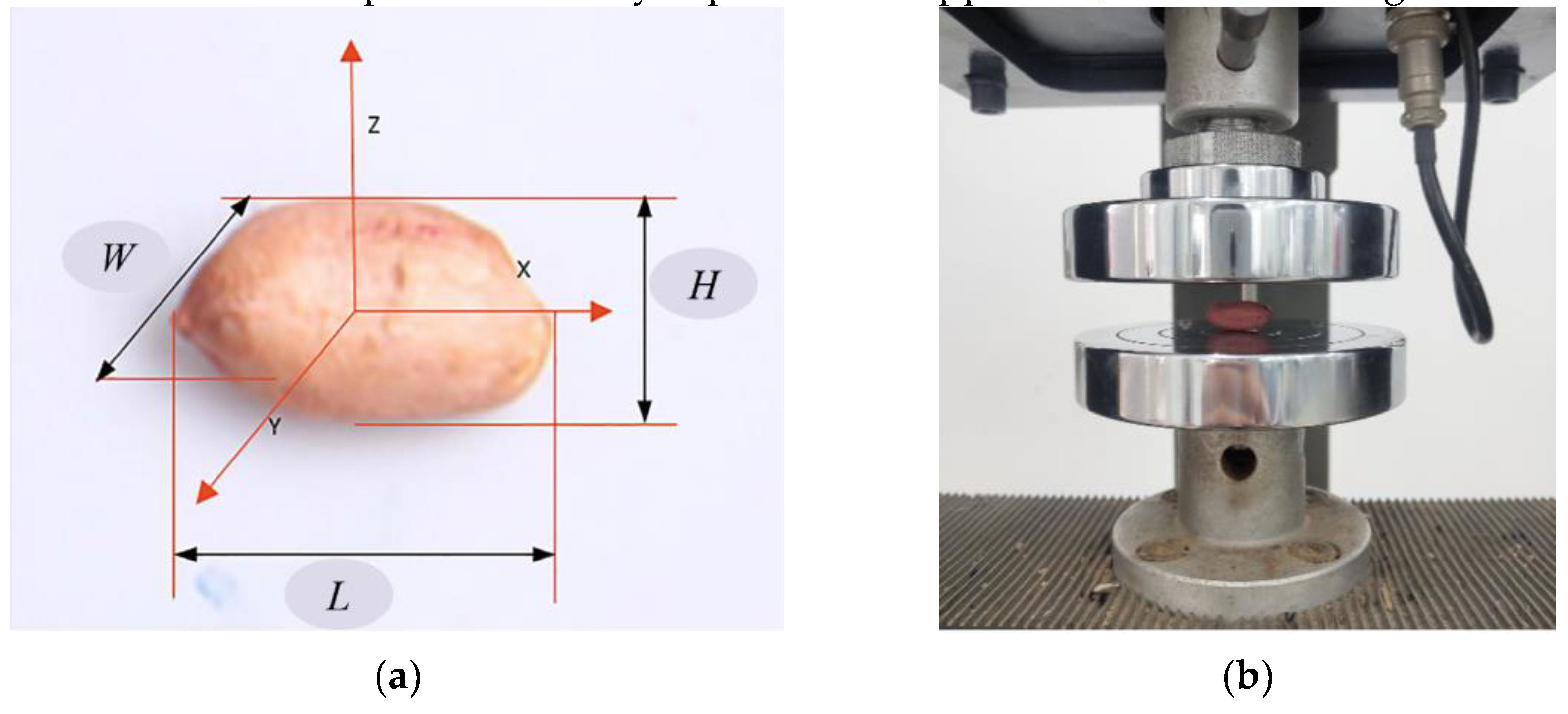
Figure 4.
Operation principle of seed supply and seed clearing devices.
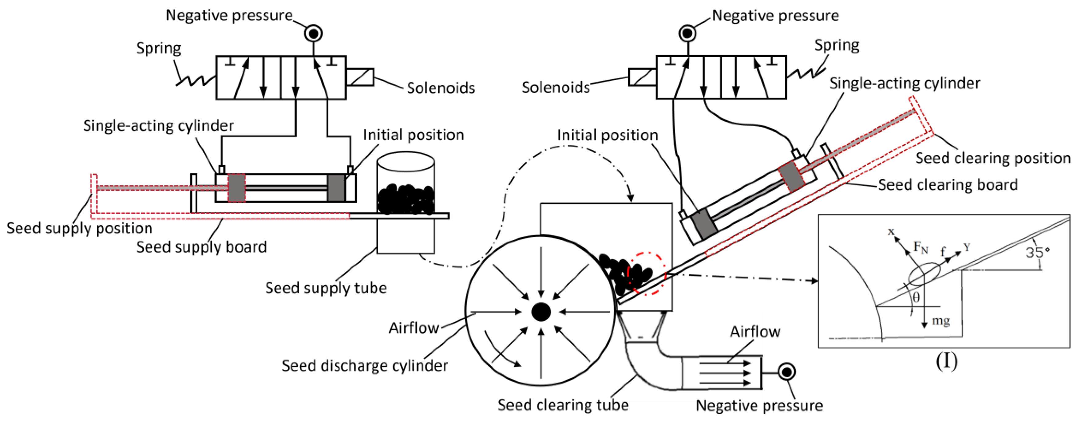
Figure 5.
Theoretical analysis of the seed absorption process.
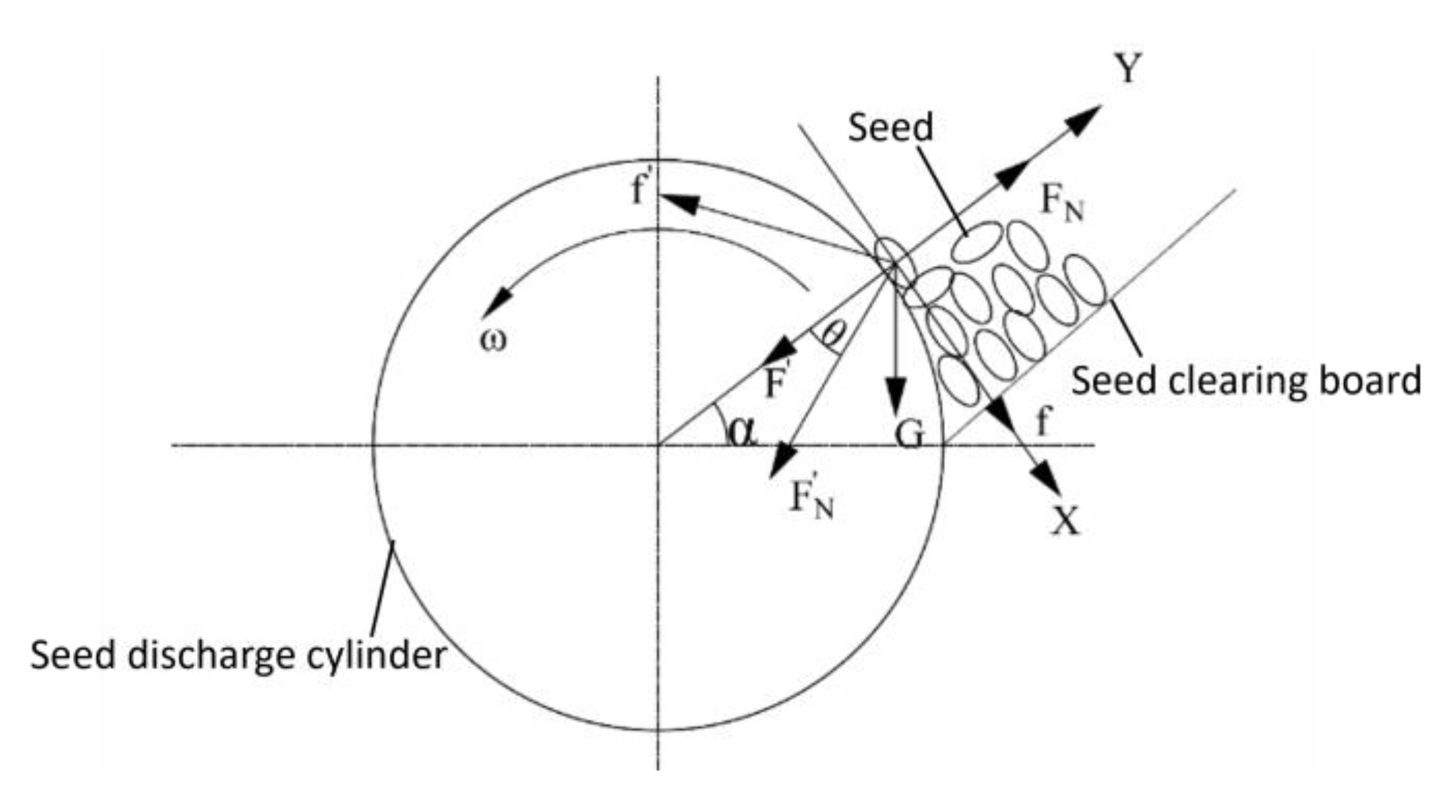
Figure 6.
(a) Seed carrying status with the angle of β in the range of 0° to 90°; (b) Seed carrying status with the angle of β in the range of 90° to 180°; (c) Seed carrying status with the angle of β in the range of 180° to 270°; (d) Seed carrying status with the angle of β in the range of 270° to 297°.
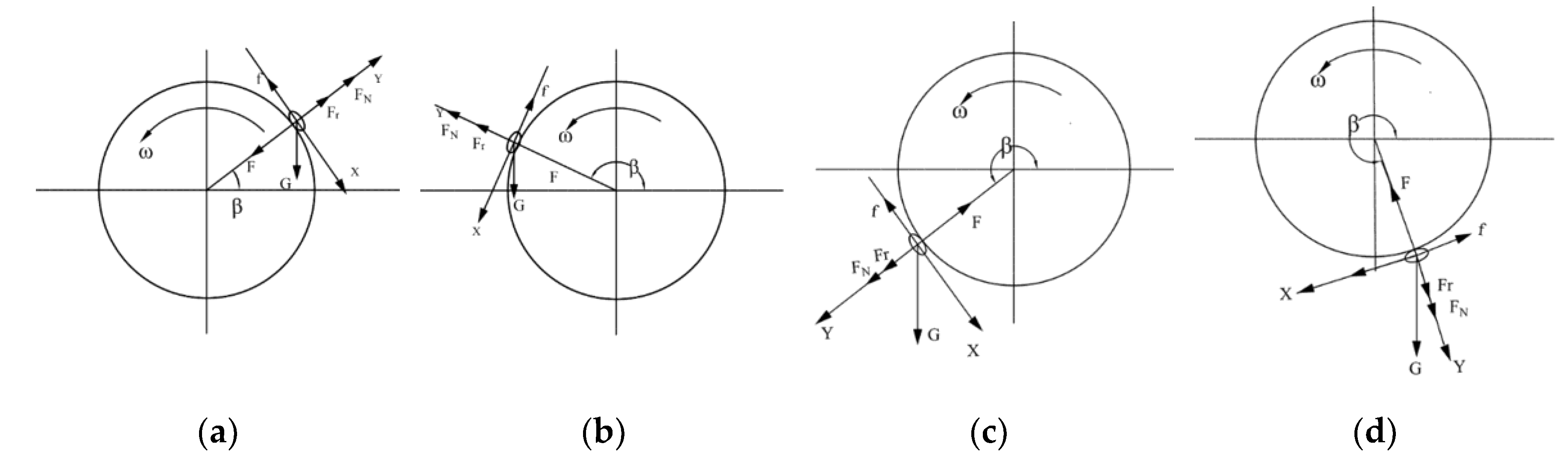
Figure 7.
(a) Structure diagram of hole plugging wheel; (b) Trajectory of seeds after being discharged; (c) Motion of seeds after loss of suction force.
Figure 7.
(a) Structure diagram of hole plugging wheel; (b) Trajectory of seeds after being discharged; (c) Motion of seeds after loss of suction force.
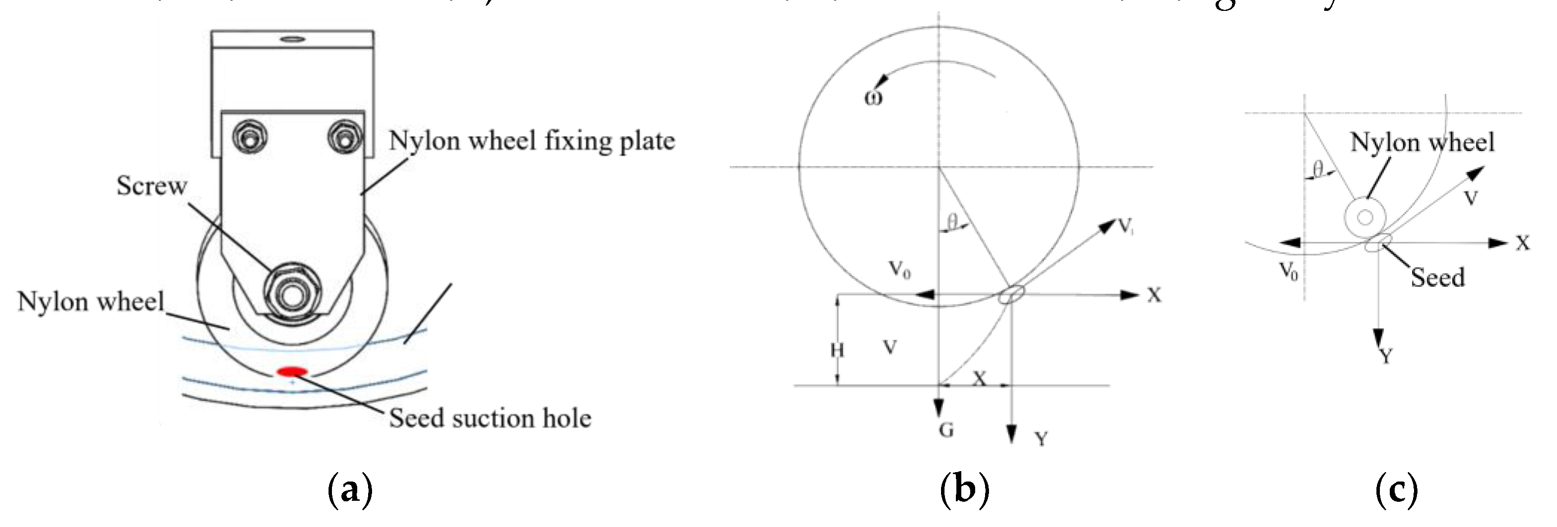
Figure 8.
The mesh of the airflow field.
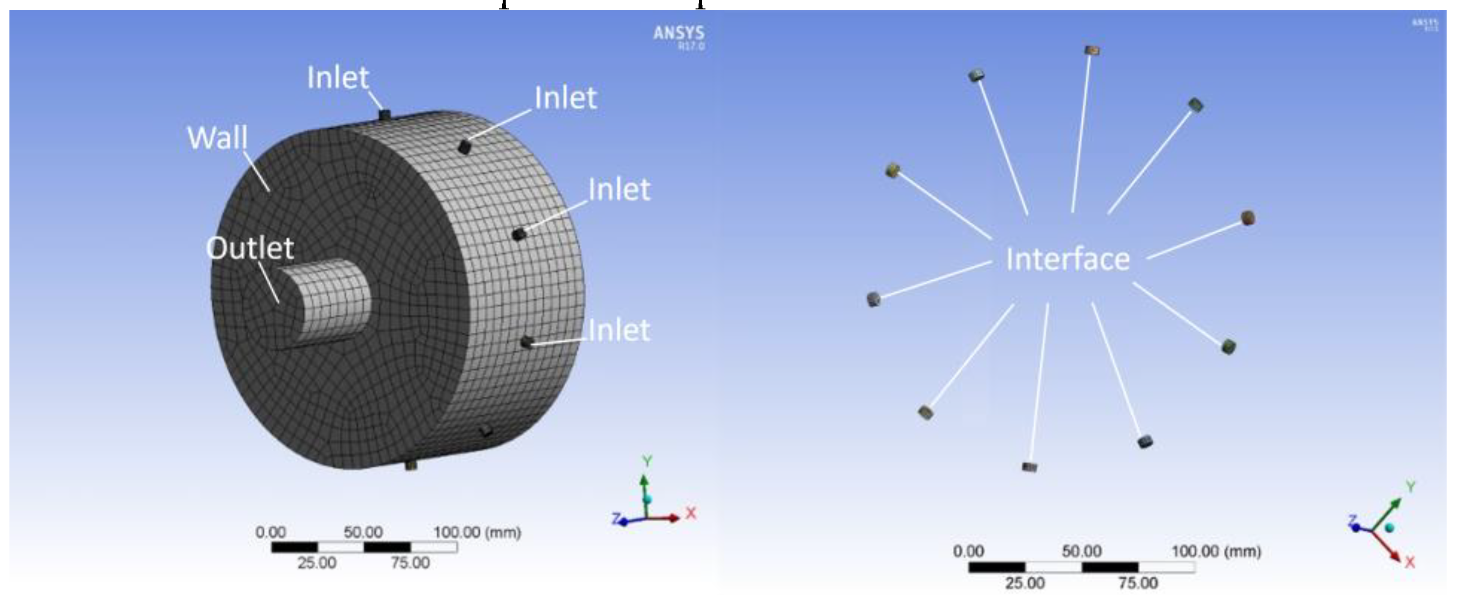
Figure 9.
(a) The flow field at the seed suction hole diameter of 5.5mm; (b) The flow field at the seed suction hole diameter of 6mm; (c) The flow field at the seed suction hole diameter of 6.5mm.
Figure 9.
(a) The flow field at the seed suction hole diameter of 5.5mm; (b) The flow field at the seed suction hole diameter of 6mm; (c) The flow field at the seed suction hole diameter of 6.5mm.
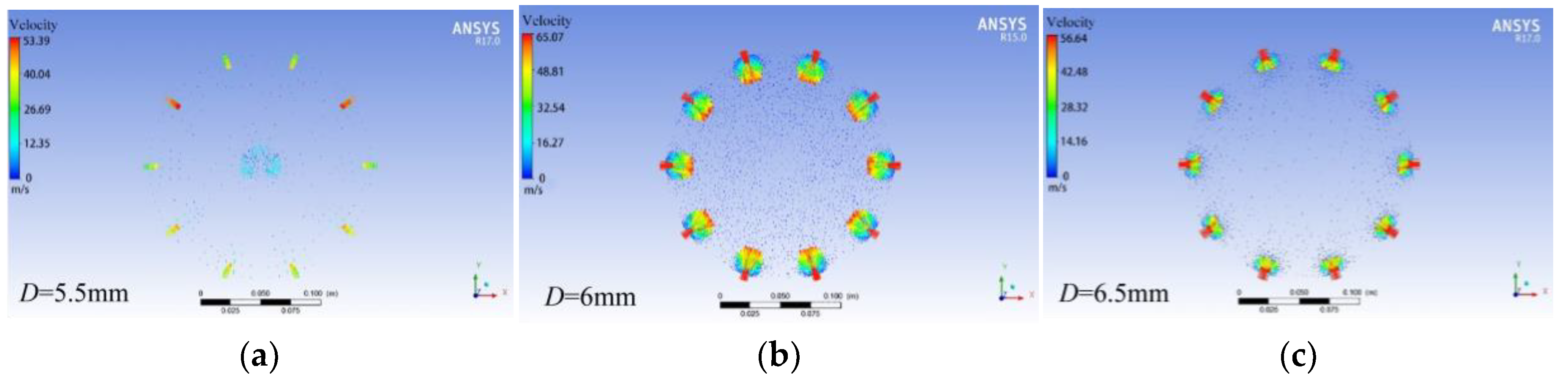
Figure 10.
The flow field at the seed suction hole diameter of 6mm.
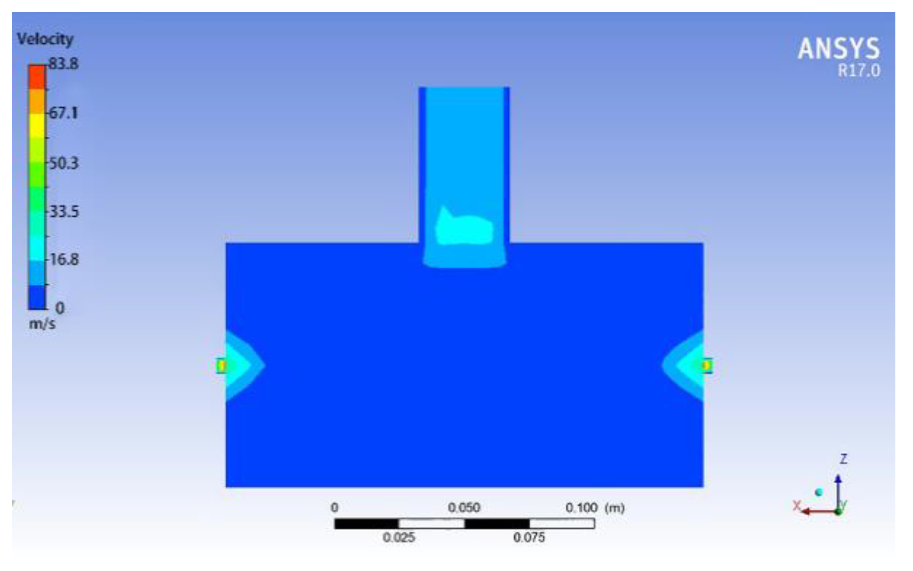
Figure 11.
(a) The flow field at the rotational speed of 20r/min; (b) The flow field at the rotational speed of 25r/min; (c) The flow field at the rotational speed of 30r/min.
Figure 11.
(a) The flow field at the rotational speed of 20r/min; (b) The flow field at the rotational speed of 25r/min; (c) The flow field at the rotational speed of 30r/min.
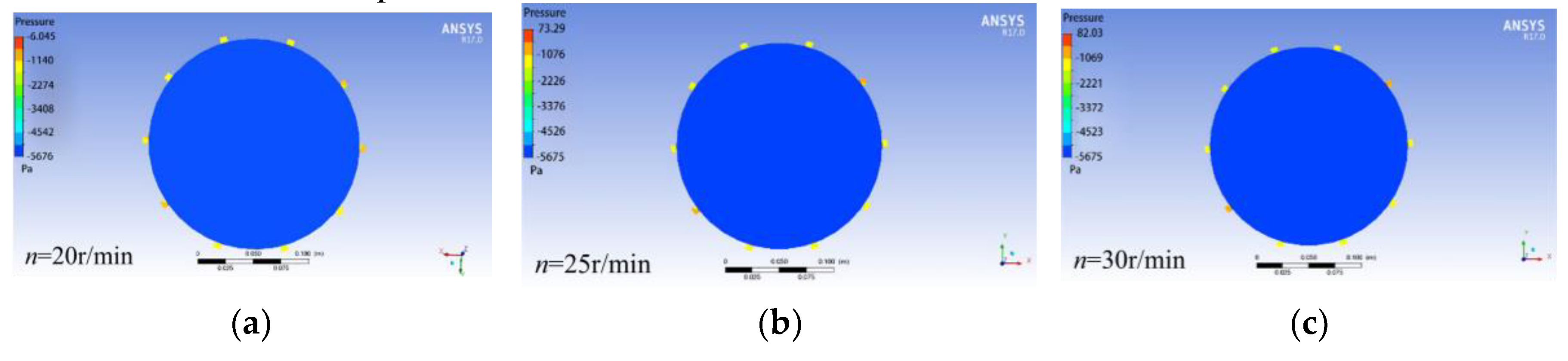
Figure 12.
(a) The flow field at the rotational speed of 20r/min; (b) The flow field at the rotational speed of 25r/min; (c) The flow field at the rotational speed of 30r/min.
Figure 12.
(a) The flow field at the rotational speed of 20r/min; (b) The flow field at the rotational speed of 25r/min; (c) The flow field at the rotational speed of 30r/min.
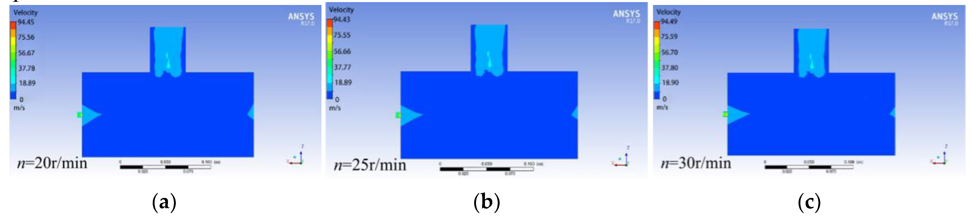
Figure 13.
(a) The flow field at the negative pressure of -4kPa; (b) The flow field at the negative pressure of -5.5kPa; (c) The flow field at the negative pressure of -7kPa.
Figure 13.
(a) The flow field at the negative pressure of -4kPa; (b) The flow field at the negative pressure of -5.5kPa; (c) The flow field at the negative pressure of -7kPa.
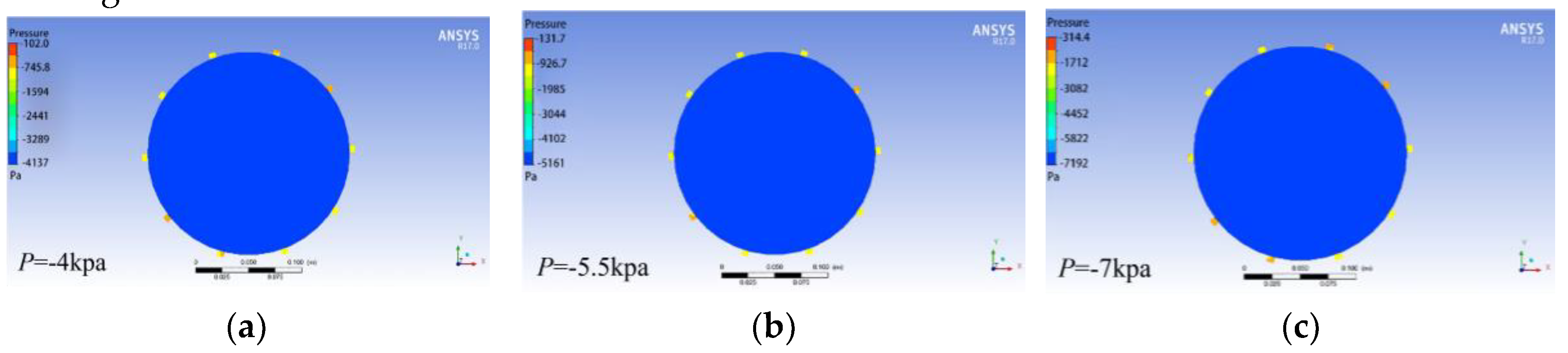
Figure 14.
(a) The flow field at the negative pressure of -4kPa; (b) The flow field at the negative pressure of -5.5kPa; (c) The flow field at the negative pressure of -7kPa.
Figure 14.
(a) The flow field at the negative pressure of -4kPa; (b) The flow field at the negative pressure of -5.5kPa; (c) The flow field at the negative pressure of -7kPa.
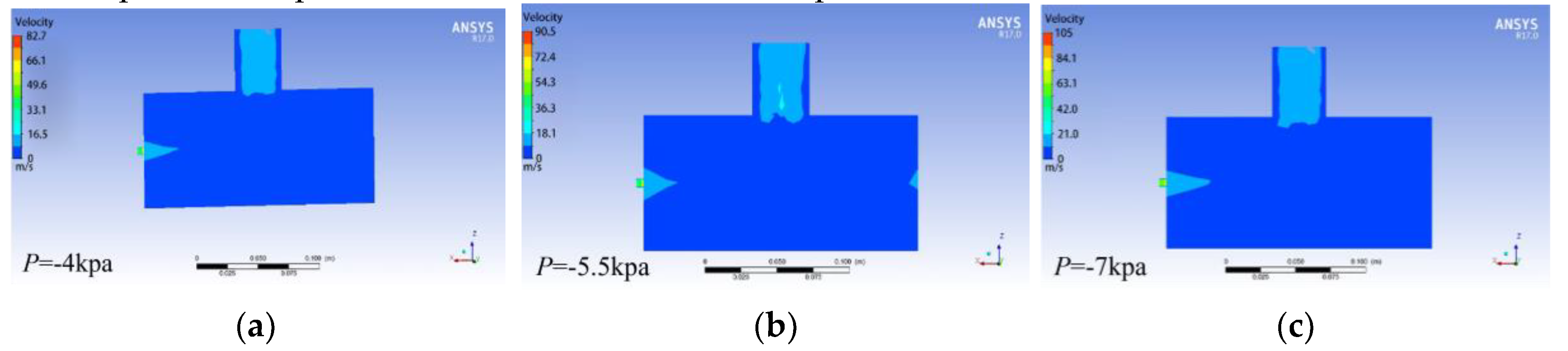
Figure 15.
Peanut seed simulation model and the discrete particle model of seed metering device.
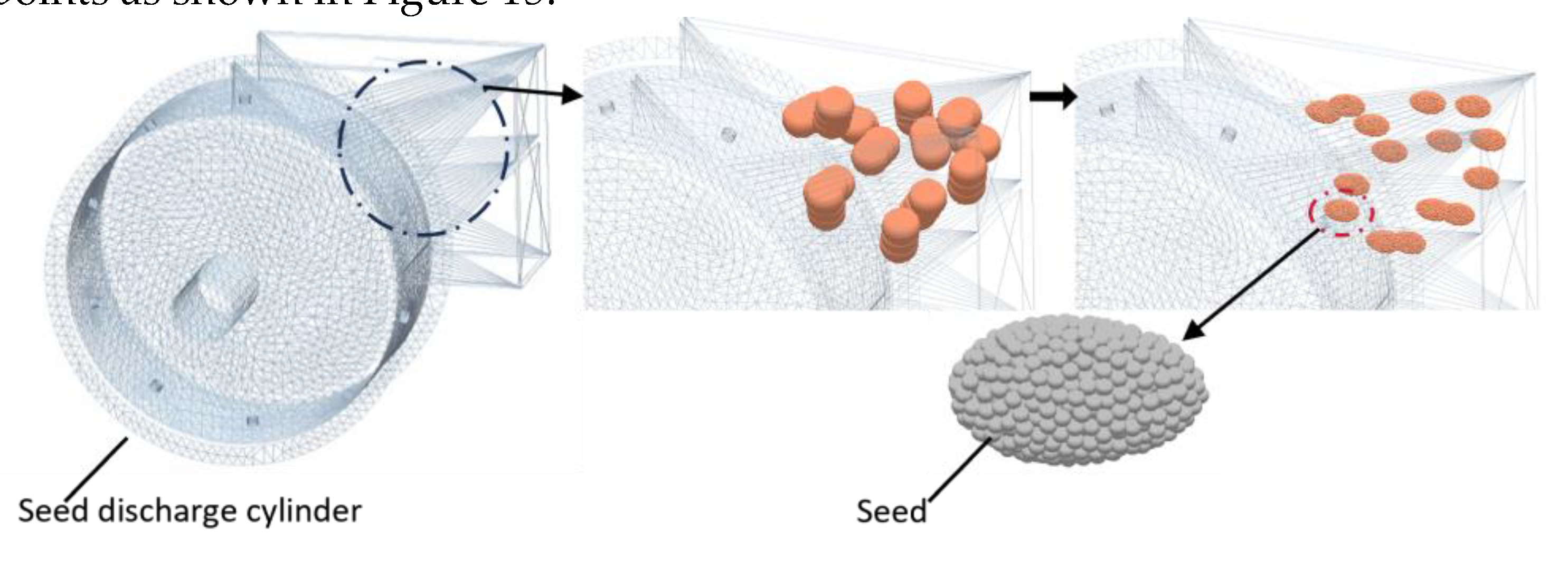
Figure 16.
Coupled simulation of the seed discharge process.
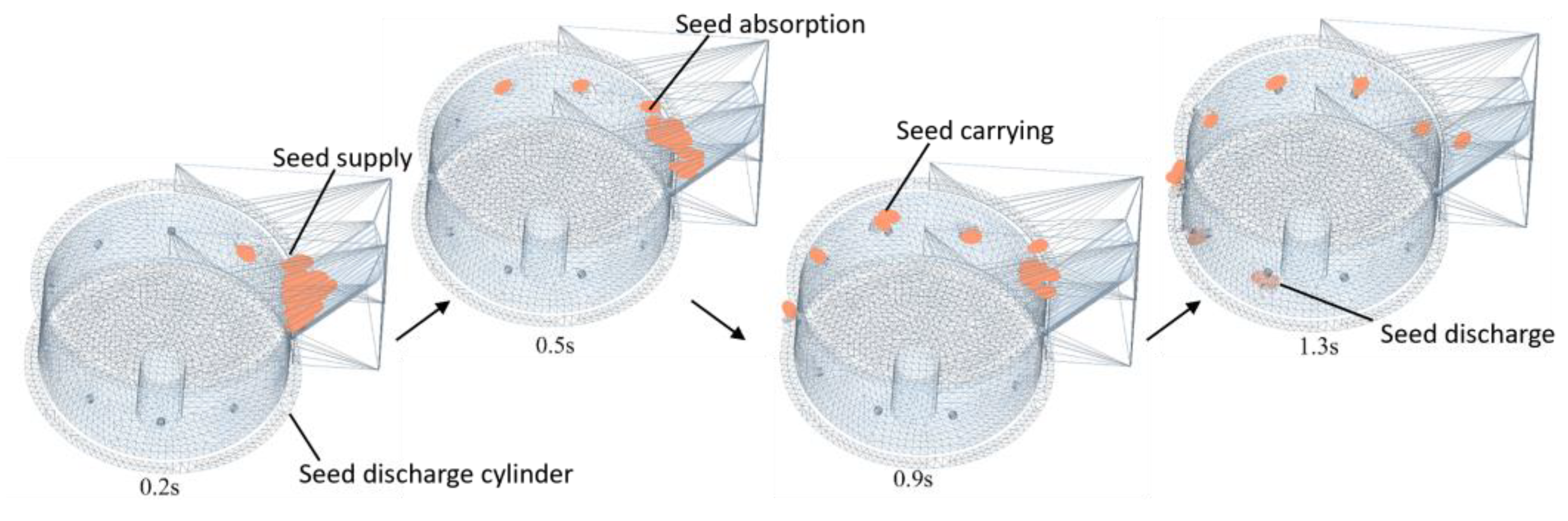
Figure 17.
(a) Velocity of the seed in the coupled field; (b) The suction force on the seed in the coupled field.
Figure 17.
(a) Velocity of the seed in the coupled field; (b) The suction force on the seed in the coupled field.
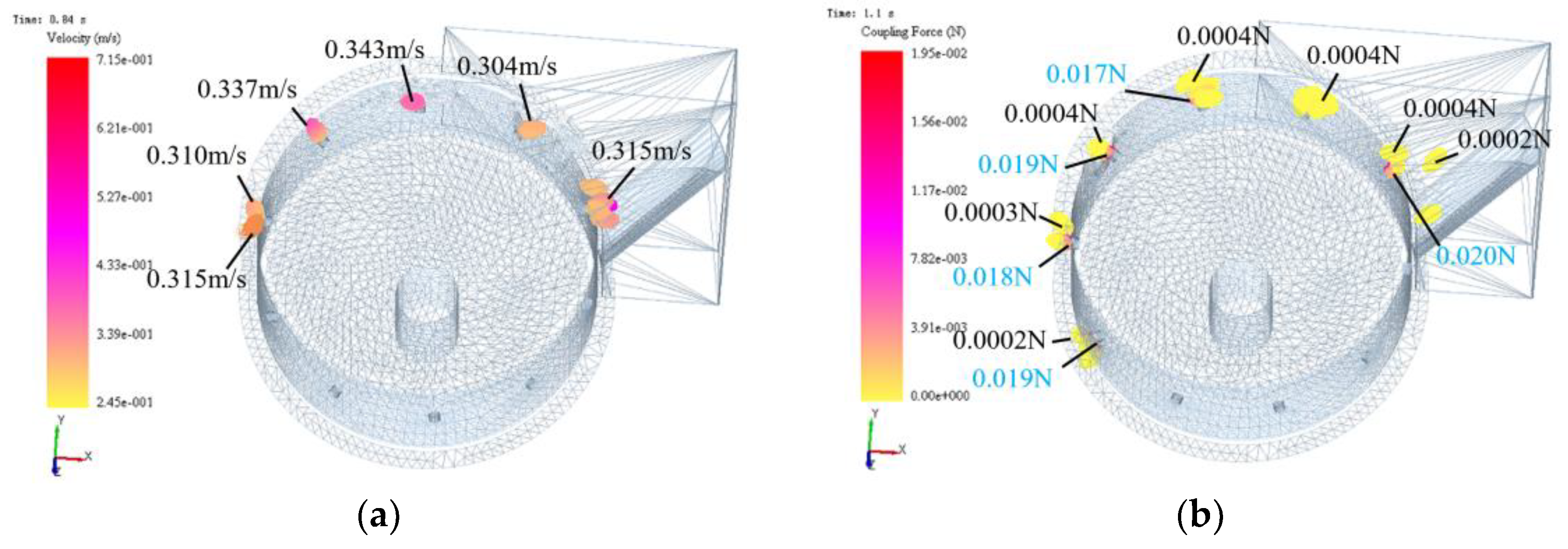
Figure 18.
The coupling simulation process of seed clearing.
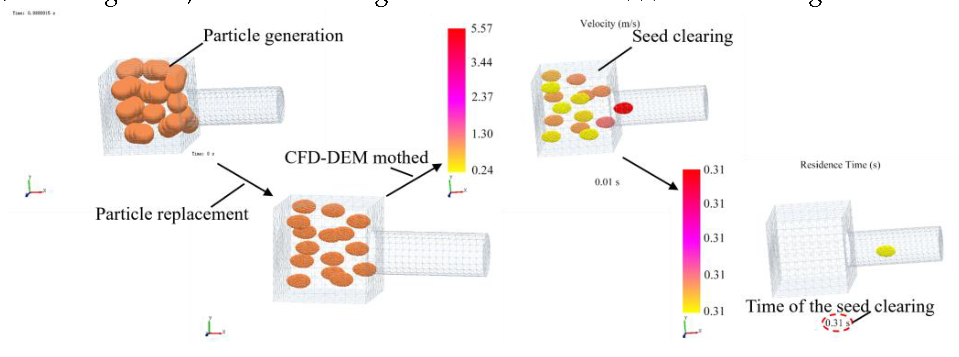
Figure 19.
Clear seed simulation analysis diagram.
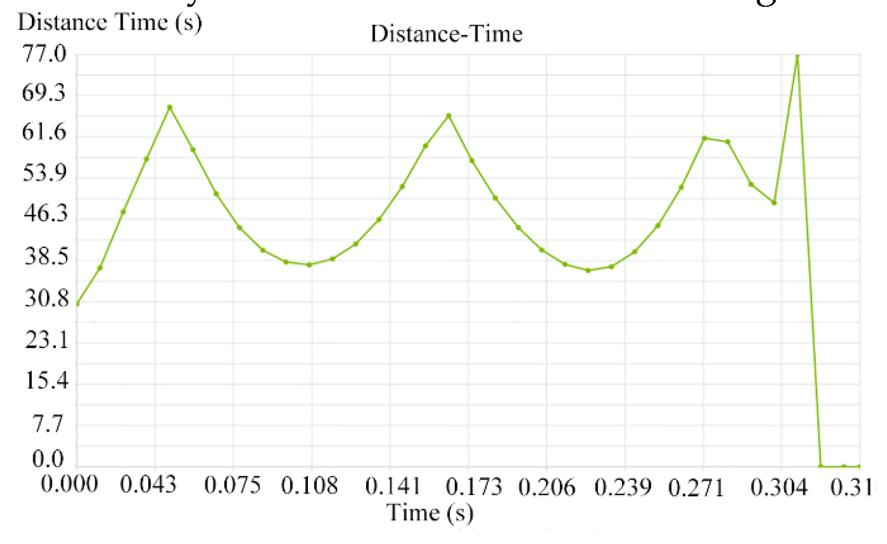
Figure 20.
(a) Test bench of the seed metering device; (b) Installation position of the seed discharger.
Figure 20.
(a) Test bench of the seed metering device; (b) Installation position of the seed discharger.
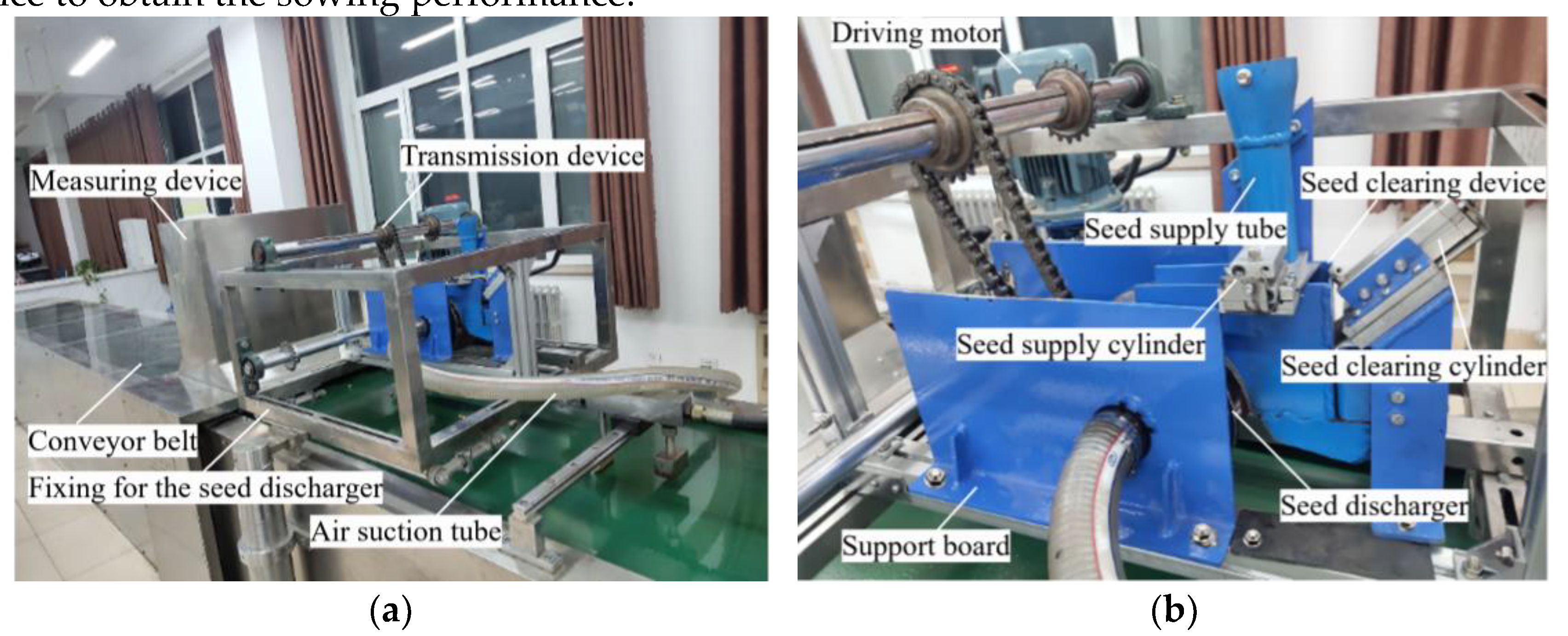
Figure 22.
(a) Response surface between seed spacing pass rate and speed as well as seed suction hole diameter; (b) Response surface between seed spacing pass rate and speed as well as negative pressure; (c) Response surface between multiple seeds rate and negative pressure as well as seed suction hole diameter; (d) Response surface between multiple seeds rate and speed as well as seed suction hole diameter; (e) Response surface between multiple seeds rate and speed as well as negative pressure; (f) Response surface between multiple seeds rate and negative pressure as well as seed suction hole diameter; (h) Response surface between seed missing rate and speed as well as seed suction hole diameter; (i) Response surface between seed missing rate and speed as well as negative pressure; (j) Response surface between seed missing rate and negative pressure as well as seed suction hole diameter.
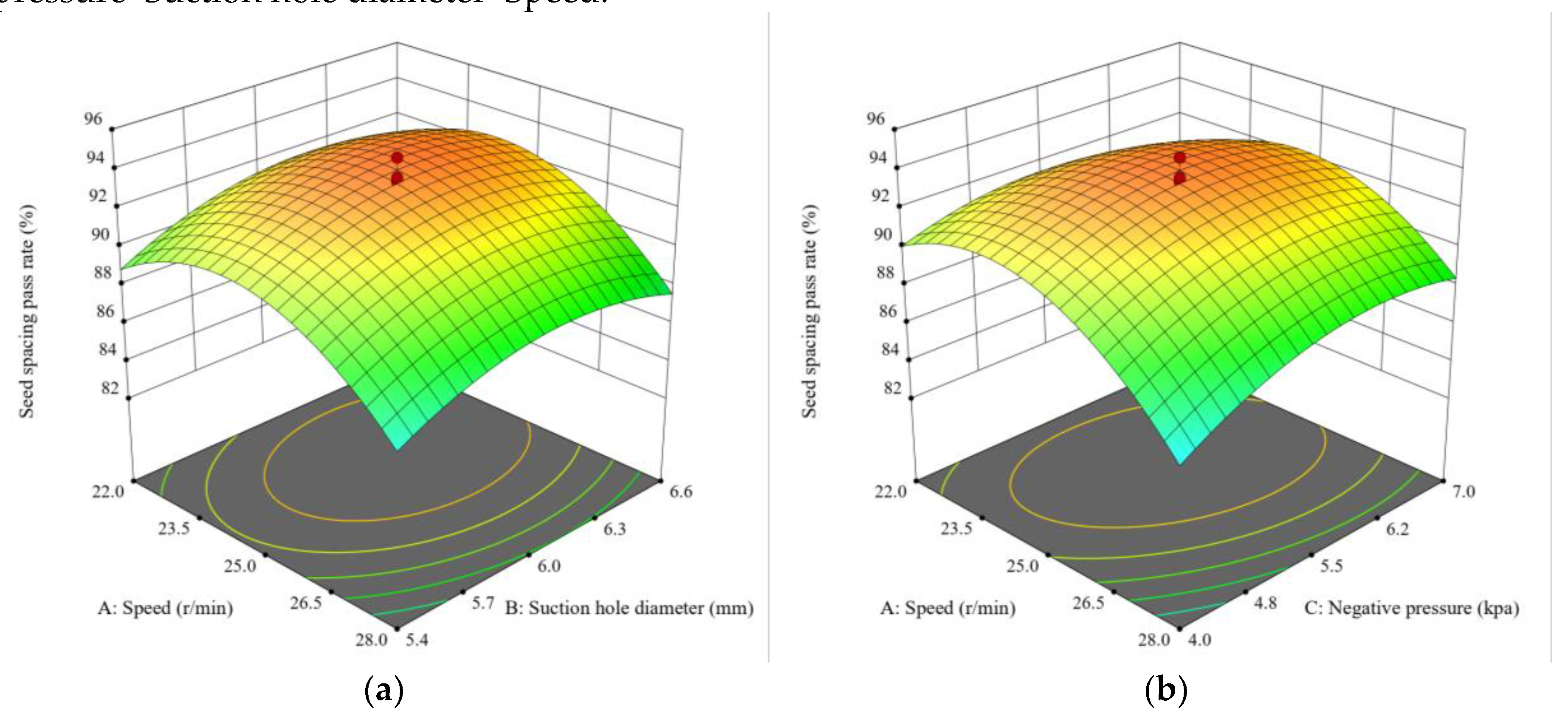
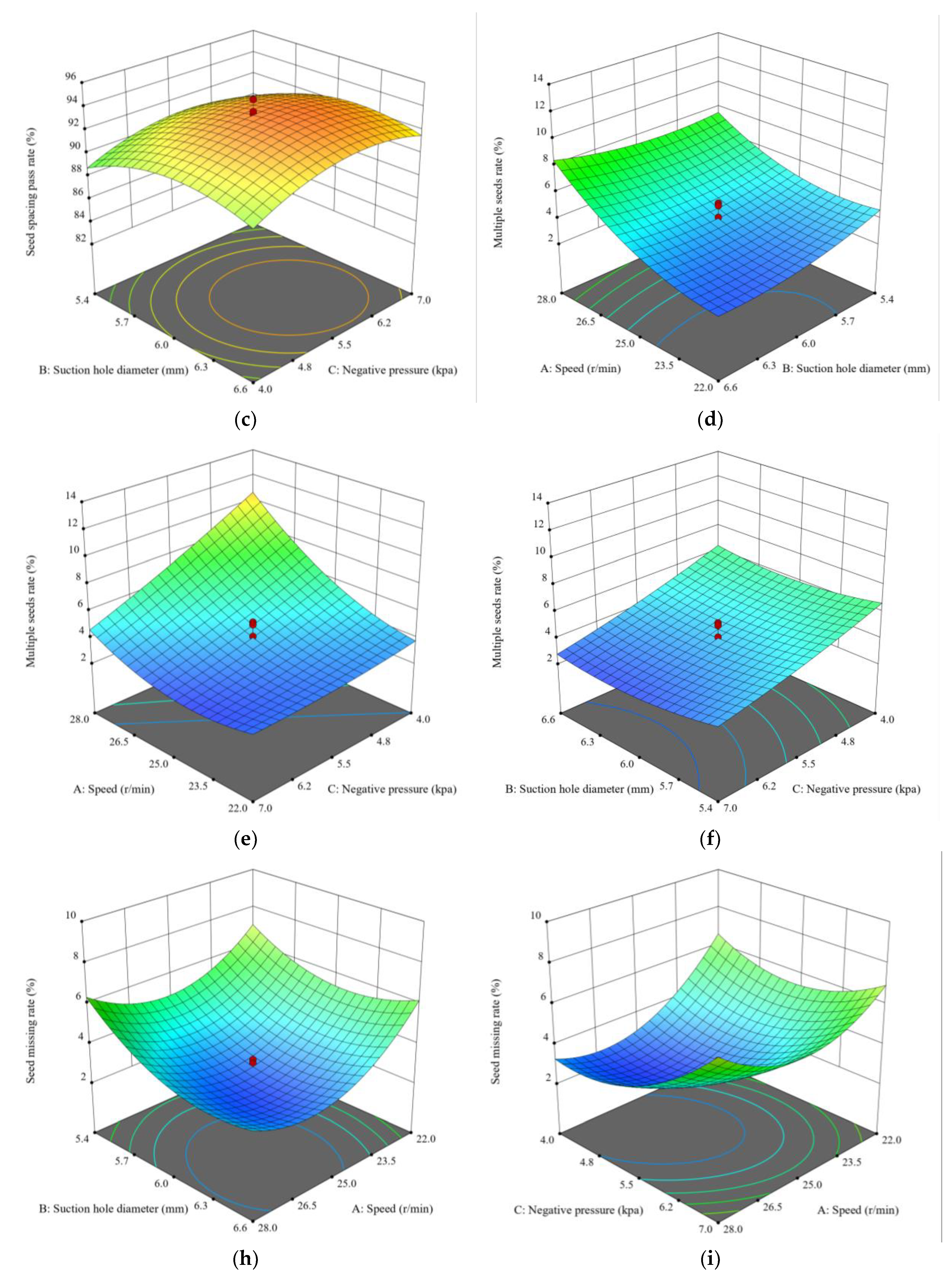
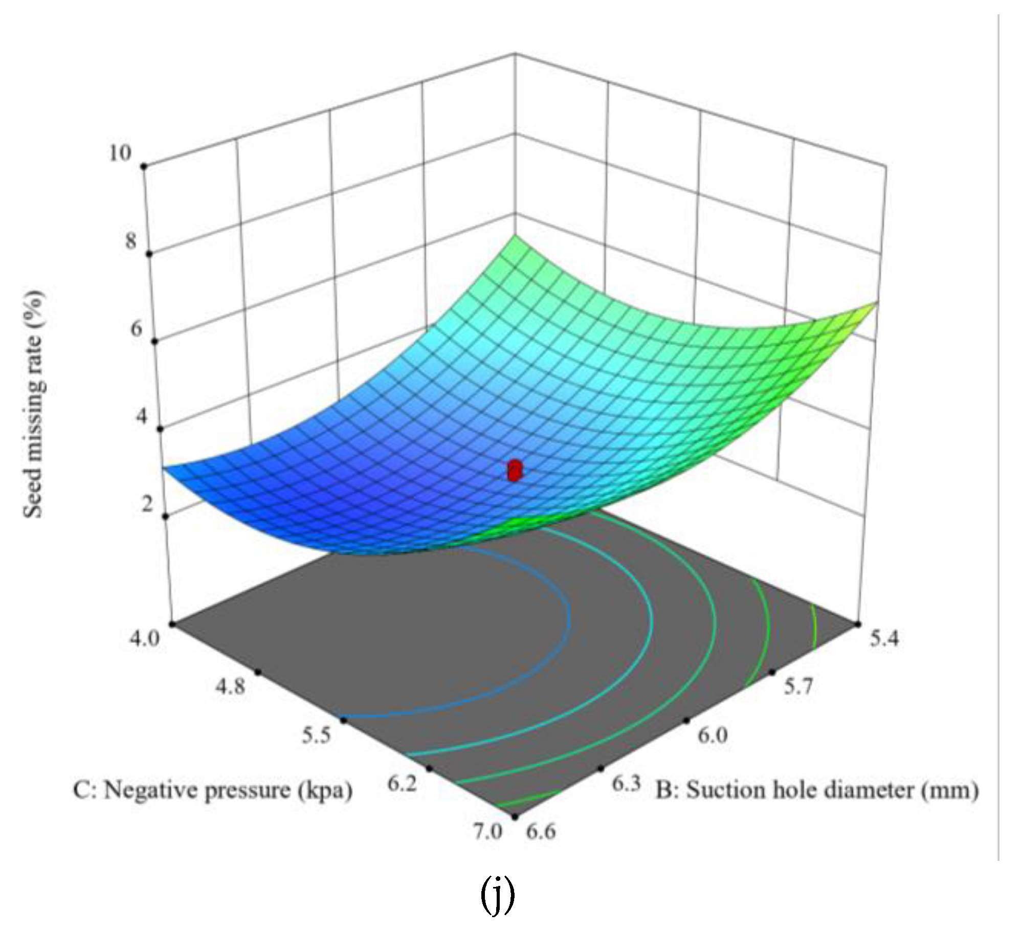
Figure 23.
(a) Installation position of the seed discharger on the planter; (b) The spacing between seeds.
Figure 23.
(a) Installation position of the seed discharger on the planter; (b) The spacing between seeds.
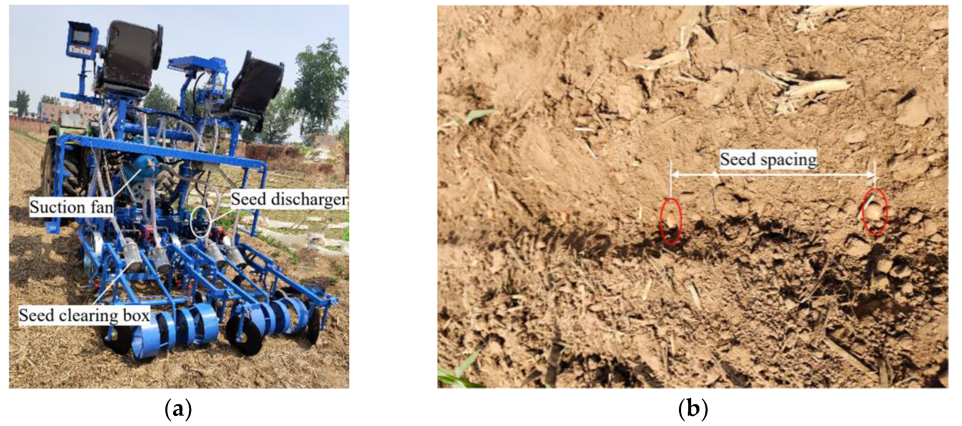
Table 1.
Material parameters and Contact parameters of peanut and seed discharger.
| variable | parameters | unit |
|---|---|---|
| Mean length of peanut seeds | 19.23 | mm |
| Mean width of peanut seeds | 9.67 | mm |
| Mean thickness of peanut seeds | 8.50 | mm |
| Density of peanut seeds | 860 | kg·m3 |
| Density of the seed discharger (stainless steel) | 7850 | kg·m3 |
| Poisson’s ratio of peanut seeds | 0.25 | 1 |
| Poisson’s ratio of the seed discharger | 0.33 | 1 |
| Elastic modulus of peanut seeds | 6e+07 | Pa |
| Elastic modulus of the seed discharger (stainless steel) | 2e+11 | Pa |
| The static friction coefficient between seed and seed | 0.50 | 1 |
| The static friction coefficient between the seed and the seed discharger | 0.30 | 1 |
| The dynamic friction coefficient between seed and seed | 0.04 | 1 |
| The dynamic friction coefficient between the seed and the seed discharger | 0.05 | 1 |
| Elastic collision recovery coefficient between seed and seed | 0.10 | 1 |
| Elastic collision recovery coefficient between the seed and the seed discharger | 0.40 | 1 |
Table 2.
Evaluation criteria for seeding indicators.
| Performance | Performance Indicator | ||
|---|---|---|---|
| Seed spacing≤10cm | Seed spacing>10~20cm | Seed spacing>20~30cm | |
| seed spacing pass rate | ≥60% | ≥75% | ≥80% |
| multiple seeds rate | ≤30% | ≤20% | ≤15% |
| seed missing rate | ≤15% | ≤10% | ≤8% |
Table 3.
Coding of factor level.
| Code value | Speed /r·min-1 | Suction hole diameter /mm | Negative pressure /kPa |
|---|---|---|---|
| -r (-1.682) | 20 | 5 | 3 |
| -1 Level | 22 | 5.5 | 4 |
| 0 Level | 25 | 6 | 5.5 |
| +1 Level | 28 | 6.5 | 7 |
| +r (1.682) | 30 | 7 | 8 |
Table 4.
Test results.
| Test programs | Test factors | Test indicators | ||||
|---|---|---|---|---|---|---|
| SpeedX1/r·min-1 | Suction hole diameter X2/mm | Negative pressureX3/kPa | Seed spacing pass rateQ/% | Multiple seeds rateR/% | Seed missing rateM/% | |
| 1 | -1 | -1 | -1 | 88.6 | 5.6 | 7.8 |
| 2 | 1 | -1 | -1 | 83.2 | 11.5 | 5.3 |
| 3 | -1 | 1 | -1 | 89.5 | 3.6 | 6.9 |
| 4 | 1 | 1 | -1 | 84.1 | 12.7 | 2.2 |
| 5 | -1 | -1 | 1 | 87.2 | 4.2 | 8.6 |
| 6 | 1 | -1 | 1 | 85.6 | 5.3 | 9.1 |
| 7 | -1 | 1 | 1 | 89.3 | 2.2 | 8.5 |
| 8 | 1 | 1 | 1 | 86.7 | 5.6 | 7.7 |
| 9 | -1.682 | 0 | 0 | 85.5 | 4.3 | 9.2 |
| 10 | 1.682 | 0 | 0 | 82.8 | 10.1 | 7.1 |
| 11 | 0 | -1.682 | 0 | 86.8 | 5.7 | 8.5 |
| 12 | 0 | 1.682 | 0 | 90.3 | 5.1 | 4.6 |
| 13 | 0 | 0 | -1.682 | 87.3 | 6.5 | 6.2 |
| 14 | 0 | 0 | 1.682 | 90.2 | 2.1 | 7.7 |
| 15 | 0 | 0 | 0 | 94.6 | 2.4 | 3 |
| 16 | 0 | 0 | 0 | 93.4 | 3.9 | 2.6 |
| 17 | 0 | 0 | 0 | 92.5 | 5.2 | 2.3 |
| 18 | 0 | 0 | 0 | 92.8 | 5 | 3.2 |
| 19 | 0 | 0 | 0 | 92.9 | 4.1 | 3 |
| 20 | 0 | 0 | 0 | 93.6 | 3.6 | 2.8 |
Table 5.
Fit Statistics of indicators.
| Indicator | Std. Dev. | Mean | C.V.% | R2 | Adjusted R2 | Predicted R2 | Adeq Precision |
|---|---|---|---|---|---|---|---|
| Seed spacing pass rate | 0.8933 | 88.84 | 1.01 | 0.9685 | 0.9401 | 0.8288 | 18.2962 |
| Multiple seeds rate | 0.9920 | 5.44 | 18.25 | 0.9375 | 0.8812 | 0.7269 | 14.3484 |
| Seed missing rate | 0.7633 | 5.81 | 13.13 | 0.9544 | 0.9133 | 0.6780 | 11.9932 |
Table 6.
Anova analysis of seed spacing pass rate.
| Source | Sum of Squares | df | F-value | P-value |
|---|---|---|---|---|
| Model | 245.11 | 9 | 34.13 | < 0.0001 |
| X1-Speed | 27.96 | 1 | 35.03 | 0.0001 |
| X2-Suction hole diameter | 8.68 | 1 | 10.87 | 0.0080 |
| X3-Negative pressure | 5.02 | 1 | 6.29 | 0.0311 |
| X1X2 | 0.1250 | 1 | 0.1566 | 0.7006 |
| X1X3 | 5.44 | 1 | 6.82 | 0.0259 |
| X2X3 | 0.2450 | 1 | 0.3070 | 0.5917 |
| X12 | 150.86 | 1 | 189.03 | < 0.0001 |
| X22 | 40.66 | 1 | 50.95 | < 0.0001 |
| X32 | 37.31 | 1 | 46.75 | < 0.0001 |
| Residual | 7.98 | 10 | ||
| Lack of Fit | 5.14 | 5 | 1.81 | 0.2653 |
| Pure Error | 2.84 | 5 | ||
| Cor Total | 253.09 | 19 |
Table 9.
Field test results.
| Test programs | Seed spacing pass rate/% | Multiple seeds rate/% | Seed missing rate/% | Seed clearing rate/% |
|---|---|---|---|---|
| 1 | 91.4 | 4.55 | 4.05 | 100 |
| 2 | 90.1 | 5.59 | 4.31 | 100 |
| 3 | 91.7 | 5.27 | 3.03 | 100 |
Disclaimer/Publisher’s Note: The statements, opinions and data contained in all publications are solely those of the individual author(s) and contributor(s) and not of MDPI and/or the editor(s). MDPI and/or the editor(s) disclaim responsibility for any injury to people or property resulting from any ideas, methods, instructions or products referred to in the content. |
© 2025 by the authors. Licensee MDPI, Basel, Switzerland. This article is an open access article distributed under the terms and conditions of the Creative Commons Attribution (CC BY) license (http://creativecommons.org/licenses/by/4.0/).
Copyright: This open access article is published under a Creative Commons CC BY 4.0 license, which permit the free download, distribution, and reuse, provided that the author and preprint are cited in any reuse.


