
Submitted:
01 January 2025
Posted:
02 January 2025
You are already at the latest version
Abstract
The similarity principle serves as the theoretical foundation for experimental research on scaled ship structures. While extensive studies have been conducted on global longitudinal responses using scaled hydroelastic segmented ship models, there is a notable gap in experimental research on scaled local ship plate structures. This research introduces a novel composite similarity principle tailored for local ship plate structures, drawing upon classical beam and plate theories. We propose a design methodology to determine the appropriate scaled model for ship plate structures. To validate our proposed similarity principle and its associated design method, we present several numerical experiments. These methods are not only expected to inform future experimental design for local ship plate structures but also to enhance the current experimental framework, contributing to a more holistic approach to ship structural experiment research.
Keywords:
similarity principle
; ship plate structure
; beam theory
; thin plate theory
1. Introduction
The experimental approach is pivotal in the field of ship structural mechanics. Extensive ship structural experiments, including full-scale and scaled segmented hydroelastic model tests [1,2,3,4,5,6,7,8,9,10,11], have been conducted to study the behavior of ship structures under environmental loads. Despite the pervasive impact of computer simulation technology across science and engineering, ship structural experiments remain indispensable for three primary reasons: (1) theoretical structural analysis methods are still evolving [12]; (2) the complexity of ship structures makes comprehensive three-dimensional dynamic simulations time-consuming [13]; and (3) the physical understanding of wave loading on ship structures in severe conditions is incomplete [12], which undermines the reliability of pure computer simulations. Given the vast size of ships, ranging from tens to hundreds of meters in length, scaled experiments are often the preferred method [12]. These experiments are designed based on the theoretical foundation of the similarity principle [14].
Due to the structural complexity of ships, the similarity principle is proposed within the framework of the classical estimation methodology for predicting total ship structural responses, as referenced in [15,16]. This methodology divides the total responses into two components: the hull girder response and the local structural response. The hull girder response is calculated by modeling the ship hull as either an Euler-Bernoulli beam [17] or a Timoshenko beam [18]. The local structural response is typically determined using a finite element (FE) model based on the original local structures [19,20,21]. The simplicity of the Euler-Bernoulli beam theory has made it widely accepted, leading to a similarity principle that guides the design of scaled hull girder experiments [14].
Most scaled hydroelastic segmented ship models are designed using an experimental methodology derived from a modified version of the similarity principle for hull girder response, as mentioned in references [2,3,4,5,6,7,8,9,10,11,12,13]. The rigorous application of the similarity principle for scaled hull girder design, as outlined in [14], demands two key conditions: (1) the length of the scaled hull girder must be similar to the length of the scaled ship model, and (2) the cross-sectional structural rigidity and mass density must be accurately replicated. However, current design methods struggle to meet these stringent requirements, leading to the adoption of a more practical approach: (1) the length requirement for the scaled hull girder is waived, (2) the cross-sectional structural rigidity is replaced with a focus on the global vibrational characteristics of the hull girder, and (3) the cross-sectional mass density is replaced with considerations of the global rigid body ship model’s center of gravity (COG) and moment of inertia. In light of these challenges, the present authors have recently introduced a novel design methodology [22] aimed at addressing the issues associated with the design of both full-scale and scaled ship hull girders.
Unlike the relatively simple structure of the hull girder, the intricacy of local ship structures presents a significant challenge in designing their scaled experimental models. The hydroelastic responses of these full-scale local ship plate structures under dynamic wave loading are predominantly studied through computational methods [20,23,24]. While small-scale local ship structural experiments have been performed [25,26], their primary purpose is to validate computational prediction methods for full-scale ship local structures, rather than serving as scaled tests that directly predict their full-scale counterparts. This research introduces a similarity principle and a corresponding scaled model design methodology for ship plate structures, which include both plate and beam components. It assumes that the flat cross-section for beams and the straight normal line for plates, as described in [16], are simultaneously valid for the ship plate structure. The proposed similarity principle is a hybrid, founded on the widely accepted Euler-Bernoulli beam theory [17] and thin plate theory [16,27]. Consequently, these methods have the potential to augment existing experimental methods for the ship hull girder, creating a more holistic experimental research framework for ship structures.
This paper is divided into five sections, each addressing a specific aspect of our research. Section 2 introduces the foundational theories: the Euler-Bernoulli beam theory and the thin plate theory. It is on these theories that we base the establishment of similarity principles for both beam and plate components within ship plate structures. Section 3 delves into the precise methodology for constructing scaled plate structures for experimental purposes. We then proceed to Section 4, where we present various numerical experiments utilizing the FE method to validate the effectiveness of our proposed methods. Finally, in Section 5, we conclude the paper with a discussion of the findings and the implications of our research.
2. Similarity Principles for Ship Plate Structure
2.1. Similarity Principle for Beam Components
The Euler-Bernoulli beam theory has been successfully adopted to establish practical design methods for scaled hull girders in experimental settings. This theory is based on several assumptions: the beam is considered slender, and its behavior is not significantly influenced by shear forces or the moment of inertia. The dynamic response of an Euler-Bernoulli beam under external loading, as detailed in [17], can be described by the following equation:
where E denotes Young’s modulus, I(x) represents the cross-sectional second moment of area at the longitudinal position x, m(x) represents the cross-sectional mass density, and P(x,t) represents the dynamic external loading per unit length at time t. y(x,t) represents the dynamic deformation of the beam. Equation (1) can be fully expanded as follows:
The similarity principle for the Euler-Bernoulli beam is established based on Equation (2), starting with the following change of variables:
where L is a representative length taken to be the length of the ship, Tθ is the natural period of pitch of the ship. Then ξ, η, and τ are the so-called non-dimensional physical quantities, representing longitudinal position, dynamic deformation and time, respectively. Substituting Equation (3) into Equation (2) and applying the chain rule in calculus leads to the following equation:
multiplying Te2/ρL3 to Equation (4):
where Te represents the encountering wave period, and ρ is the mass density of the ship material. Equation (5) is the non-dimensional version of Equation (2). Note that, in common ship hull girder experimental research, ρ in Equation (5) is usually denoted as the water density [14]. This distinction marks the first difference between the established hull girder similarity principle and the new similarity principle proposed in this research. Te and Tθ can be further expressed as follows [14]:
where the meanings of K1 and K2 are clarified in [14](in Section 8.3), and we omit the explanations here for brevity. Equation (5) can then be re-written as follows:
Suppose that both the full-scale beam component and the scaled model beam component satisfy Equation (2). Then, their non-dimensional vibrational equations are also both expressed by Equation (7). Consequently, the similarity principle for the beam component can be established as follows:
where the subscripts 1 and 2 denote the full-scale beam component and the scaled beam component, respectively, with the exception of L1 and L2. L1 and L2 represent the full-scale ship length and the scaled ship model length, respectively. It should be noted that, the full-scale beam components are extracted from the full-scale ship plate structure, while the scaled beam components are extracted from the targeted scaled ship plate structure. Equation (8) can be proven to reduce to the following equations(please refer to the Appendix A for detailed proof):
Equation (9) has the same form as the established hull girder similarity principle presented in [14]. However, in those applications, it is commonly assumed that E1=E2 and ρ1=ρ2=ρW [14],where ρW denotes the water density. In contrats, this research requires that E1≠E2 and ρ1≠ρ2. ρ1 and ρ2 here represent the material mass densities of the full-scale and scaled beam components, respectively. The rationale for this requirement will be manifested in the next subsection.
2.2. Similarity Principle for Plate Components
The plate component, such as the plate structure at the bottom of a ship, is typically simplified as a thin plate. The equation of motion for a thin plate [16,27], under the assumption of a plane stress condition, can be expressed as follows:
where the dependencies of w, m and qd on (x,y,t) are omitted for brevity. w denotes the dynamic deformation of the thin plate, m represents the mass density, and qd signifies the external dynamic loading. D is the so-called bending rigidity of the thin plate [16], and the expression for D is as follows:
where b represents the thickness of the plate. μ is the Poisson’s ratio, which is related to σx and σy, denoting the normal stresses in the x and y directions, respectively. We carry out similar non-dimensionalization procedures as those in the previous subsection, beginning with the similar variable transformation process:
where L also represents the length of the ship. Substituting Equation (12) into Equation (10) yields the following equation:
Multiplying Te2/ρL2 to Equation(13):
which, with reference to Equation (6), is equivalent to the following equation:
where Equations (14) and (15) represent the non-dimensional versions of Equation (10). The similarity principle is then established based on Equation (15):
which can be reduced to the following expressions:
where the subscripts 1 and 2 in Equations (16) and (17) have the same meaning as those in Equations (8) and (9). Substituting Equation (11) and the expression m=ρb into Equation (17) leads to the final expressions of the similarity principle of thin plate as follows:
2.3. Combined Similarity Principle for Plate Structure
Since a plate structure is composed of both beam and plate components, it is necessary to combine Equation (9) with Equation (18) to derive the combined similarity principle for the composite plate structure. A prerequisite for this combination is that the flat cross-section assumption for the beam and the straight normal line assumption for the plate are both satisfied simultaneously. The first two equations within Equation (18) imply the following:
Here we denote Equation (19) as the material design requirement. Note that, in the similarity principle of the beam, L1/L2 is denoted as the scaling ratio λ, which implies that Equation (19) can be further re-written as follows:
Subsequent analysis reveals that the material design requirement correlates the plate material parameters with the scaling ratio, which is fundamentally different from the details of the beam’s similarity principle. Equations (19) and (20) thus indicate that the scaling ratio λ for the thin plate cannot be chosen arbitrarily; this, in turn, limits the selection of the same λ in Equation (9). In contrast, Equations (19) and (20) may or may not impose the same restriction on the choice of E2 from Equation (20) when applied to Equation (9). The strategy is to initially assume that E2 in Equation (20) is identical to E2 in Equation (9), implying that the scaled beam and plate components will be fabricated from the same material. Should this assumption lead to inconsistencies during actual implementation, it will be reconsidered.
The third equation within Equation (18) must be consistent with the third equation within Equation (9), as the external loading on the beam components of the plate structure originates from the external wave loading on the outer plate component. This implies that the third equation in Equation (18) indicates the following:
Linear wave theory [28] implies that the dynamic wave pressure is proportional to the wave amplitude. Therefore, Equation (21) requires that the scaling ratio for the wave amplitude be λρ1/ρ2, which is different from the familiar wave amplitude scaling ratio λ in existing scaled hydroelastic ship models.
P(x,t) in Equation (9) represents the internal interaction exerted on the beam component by the contacting plate component. The density of this internal interaction is denoted as q(x,y,t). If the contacting width B is relatively small, then q(x,y,t) can be approximated as constant along B. Consequently, P(x,t) can be derived from q(x,y,t) using the following expression:
The internal interaction q(x,y,t) between the plate component and the beam component is generated by the external loading qd applied to the plate component. Then the following relationship holds:
where α is a coefficient, it implies that q1/q2 is proportional to qd1/qd2. By substituting Equation (21) into Equation (23), the following relationship holds:
substitute the third equation from Equation (9) into Equation (24):
Equation (25) is the relation that ensures the validity of the third equation in Equation (9). Consequently, the proposed combined similarity principle for the plate structure can be written as follows:
2.4. Scaling Relations for Physical Quantities
The purpose of scaled ship structural experiments is to directly predict the full-scale ship structural responses based on the measured physical quantities from these experiments. This subsection presents the scaling relations of physical quantities derived from the proposed combined similarity principle for plate structures. The vertical bending moment (VBM) and the normal stress for the scaled Euler-Bernoulli beam component are expressed as follows [16]:
Similarly, the VBM and normal stress for the full-scale Euler-Bernoulli beam component are accordingly expressed as follows:
The similarity principle ensures that
By substituting the first expression from Equation (26) into the first expression of Equation (28), and the second expression from Equation (27) into the second expression of Equation (28), the scaling relations for the VBM and the normal stress of the beam components can be derived as follows:
where it is evident that Equation (30) differs from the familiar scaling relations designed for scaled hydroelastic segmented ship model tests. The reason why z1/z2 is not canceled by 1/λ is due to the fact that the vertical position of the COG of the scaled beam component may not satisfy the similarity principle. This is not a compromise because the vertical position of the COG is not included in Equation (1).
For the scaled thin plate, the plane stress components are expressed as follows [16]:
while the same stress components for the full-scale thin plate are outlined as follows:
Since the followings hold:
Based on Equations (31)–(33), the corresponding scaling relations can be derived as follows:
Similarly, based on the expressions for the bending moment and torsional moment of the thin plate [16], the corresponding scaling relations can be derived as follows:
The necessary derivation details for Equation (35) can be found in the Appendix A. In addition to the relatively complex scaling relations mentioned above, the deformations of the full-scale beam and plate components can be easily determined based on the corresponding measured deformations, as follows:
3. Numerical Experiment Design Methodology
The first step towards fully realizing a similarity principle is the numerical experiment. This subsection proposes a numerical experiment design methodology for the proposed combined similarity principle of the ship plate structure, which should be considered a prerequisite for subsequent realistic physical experiments.
The proposed numerical experiment design methodology employs a two-step strategy. The first step involves designing the scaled plate component. With the known material parameters E1, μ1 and ρ1 of the targeted full-scale ship plate structure, the scaling ratio λ and the material parameters E2, μ2 and ρ2 of the scaled experimental ship plate structure must be determined simultaneously, based on the fourth and fifth relations in Equation (26). The uniform scaling ratio for the length, width, and thickness of the experimental plate components is exactly λ. It is evident that the available choices for λ, E2, μ2 and ρ2 are, in fact, quite limited, which is a major distinction from the experimental design methods derived from pure beam theory-based similarity principles. It may be anticipated that future new materials with special material parameters may gradually broaden the range of the aforementioned choices.
The second step involves designing the beam components. As mentioned previously, the vertical position of the COG is not a necessary requirement in the proposed combined similarity principle because it is not included in Equation (1). It is possible to introduce the scaling relation of the vertical position of the COG into Equation (26) for the consideration of rigid body motion of the plate structure. This research primarily focuses on the pure elastic response of ship plate structures, and therefore, the consideration of the vertical position of the COG is currently outside the scope of this study. If the full-scale beam component has a constant rectangular cross-section, the cross-section of the scaled beam component can also be assumed to be a rectangle. The first and second equations in Equation (26) lead to the following equation:
where H1 and H2 denote the heights of the full-scale and scaled rectangular beam components, respectively. Furthermore, the second equation in Equation (26) implies that
Substituting Equation (37) into Equation (38) results in the following scaling relations:
Based on Equations (37) and (39), the width and height of the scaled beam component are determined. The next task is to verify whether the third equation in Equation (9), which is now equivalent to the third equation in Equation (26), holds. The fifth equation in Equation (26) indicates that:
If the Poisson ratio of the full-scale plate structure material is relatively close to that of the scaled plate structure material, then the following relationship holds:
If both the thicknesses of the full-scale and scaled plate components are sufficiently thin, which is guaranteed by their applicability to the thin plate theory in the first place, the coefficient α should be close to 1. Then it is found that Equation (25) holds approximately, as shown below:
This approximation will inevitably introduce the so-called scaling effect to both the proposed numerical experiment and its future physical experiment design methodologies. This scaling effect may be mitigated if the full-scale and scaled plate structure materials share the same Poisson ratio. This condition could potentially be met by advancements in materials science.
The assumption that the full-scale beam component should have a constant rectangular cross-section may seem overly simplistic, as many types of ship plate structures have beam components with cross-sections that are not entirely rectangular. For instance, a beam component might carry a top flange plate, forming a T-shaped total beam component. For these more complex ship plate structures, the composite T-shaped beam component is divided into the beam web and the top flange plate. The beam web is scaled according to the aforementioned beam scaling theory, while the top flange plate is scaled based on the scaling theory for thin plate components. The proposed similarity principle should be applicable to a variety of ship plate structures.
4. Verification by Numerical Experiments
This section aims to verify the proposed combined similarity principle and its numerical experiment design methodology for ship plate structures. The materials currently available will be utilized for the numerical experiments. Given a steel material that may be used in the construction of plate structures in real steel ships, then based on the fifth equation in Equation (26), the allowable materials for the numerical plate structure can be determined. Table 1 presents a realistic steel material and two possible materials. The data in Table 1 indicate that for realistic steel materials, it is possible to find multiple allowable materials to manufacture the expected experimental plate structures. The resulting scaling ratios λ may take quite different values for different experimental materials, and these scaling ratios may not necessarily be integers.
The two types of engineering plastics listed in Table 1 will be used to design the numerical plate structures in this section, while the steel material in Table 1 will serve as the realistic ship structure material. Suppose we have a realistic steel plate with dimensions of length, width, and thickness being 1000 mm, 1000 mm, and 30 mm, respectively. This realistic plate will serve as the full-scale plate component in the subsequent numerical examples. Next, suppose we have a realistic steel beam with dimensions of length, width, and height being 1000 mm, 10 mm, and 100 mm, respectively. This realistic beam will then be adopted as the full-scale beam component in the numerical experiments. The dimensions suggest that the aforementioned randomly selected “realistic” plate and beam could be taken from a relatively small ship. It’s important to note that the specific dimensions of the so-called realistic plate structure will not influence the subsequent numerical analysis and results. The purpose of this subsection is to validate the proposed methods rather than to focus on a particular type of realistic ship. The determination of material parameters for scaled plate structures, as outlined in Table 1, is fundamentally different from the selection of dimensions of the plate structures. While the dimensions of plate structures can be manufactured to meet specific requirements, material parameters require meticulous determination and cannot be assigned at random. Their selection is pivotal and must be grounded in the properties of available materials. For instance, it is feasible to procure a plate with a thickness less than 0.5 mm, but it is not possible to obtain a plate with material parameters that are arbitrarily assigned. The material properties must align with the physical and mechanical characteristics of the materials that exist and are suitable for the intended application. The dimensions of the scaled plate and beam components are presented in Table 2. A comprehensive set of numerical experiments are carried out based on the plate structure components presented in Table 2.
4.1. Pure Thin Plate Component
We begin by utilizing pure plate models to gradually validate the proposed theoretical framework. We assume that the external dynamic loading is uniformly distributed across the plates. The dynamic loading is designed as follows:
where P represents the amplitude of the dynamic loading, and ω represents the circular frequency. The trigonometric representation of the dynamic loading effectively captures the actual characteristics of wave loading, offering a satisfactory reflection of the actual physical phenomena.
For the first engineering plastic in Table 1(λ=10.45), P1/P2=78.375, ω1/ω2=0.309, t1/t2=3.233. For the second engineering plastic(λ=24.74), P1/P2=78.375, ω1/ω2=0.201, t1/t2=4.974. The full-scale and scaled thin plate components are modeled and further analyzed by a recent version of the ABAQUS software(www.3ds.com/products/simulia/abaqus). The amplitude P1 is set to be 0.49 MPa, which corresponds to the static water pressure exerted by a 48.7 m column of water. The circular frequency ω1 is set to be 0.68 rad/s, which corresponds to a regular wave with a natural period of approximately 9 seconds. Given the values of P1 and ω1, the corresponding scaled values of P2 and ω2 for different scaling ratios can be derived. As previously stated, the specific values of P1 and ω1 will not influence the subsequent numerical simulations and analyses. This is because our focus is on the structural aspects rather than a detailed fluid dynamics analysis. The above-mentioned P1, P2, ω1 and ω2 will be adopted in the following numerical examples.
Both the full-scale and scaled plates are modeled by the shell elements. A total of 10,000 shell elements are used to establish the FE models of the full-scale and scaled plates, as shown in Figure 1. The structural responses of the plates under their respective external loadings are calculated using the ABAQUS software (www.3ds.com/products/simulia/abaqus). From these calculations, the smooth structural responses are selected for further comparison. It should be noted that the structural responses in the forthcoming numerical examples are calculated under the same general settings as those used in the numerical example presented in this subsection. Hence, for the sake of brevity, the specific chosen periods of structural responses and the software utilized will not be reiterated in the forthcoming numerical examples. Figure 2 illustrates the deformation contours for both the full-scale plate and one of the scaled plates (λ=10.45). For the subsequent comparison of structural responses, the shell element with the largest elastic deformation in each plate’s FE model is chosen. The vertical deformation and the three stress components—namely, the two normal stresses and the shear stress—of the plates are found to be in good agreement, with the largest relative error being less than 0.3%, as shown in Figure 3. This high level of accuracy validates the proposed similarity principle for thin plates.
As illustrate in Figure 3d, the shear stresses in the plates are notably smaller compared to the two normal stresses. Furthermore, due to the geometrical symmetry of the plate, which is characterized by equal length and width, the two normal stresses are consequently equal. For the sake of brevity and without loss of generality, in the subsequent numerical examples, the focus will be on the normal stresses of non-symmetrical plate structures, as well as one of the normal stresses of symmetrical plate structures. In addition, only the first engineering plastic with a scaling ratio of λ=10.45 will be utilized as the material for the scaled plate structures in the forthcoming numerical examples.
4.2. Pure Beam Component
This subsection focuses on the pure beam component, aiming to verify the proposed scaling relations in Equation (30). In most existing scaled ship hull girder experiments, only the scaling relations for bending moments have been proposed and analyzed. Therefore, a so-called calibration process, which correlates the strains and bending moments of the scaled ship hull girder, is necessary. The proposal of a direct scaling relation for normal stress, as presented in Equation (30), may help eliminate the aforementioned calibration process, which could consequently help reduce the time spent on preparing a hydroelastic segmented ship model test.
All the beam components are also modeled by the shell elements. Each FE model of the beam component is composed of 6250 shell elements, as shown in Figure 4. The deformation contours of both the full-scale beam and the scaled beam, constructed from the first engineering plastic, are illustrated in Figure 5. For the subsequent comparison of structural responses, the middle shell element on the top side of the beam has been selected. Figure 6 shows that the structural responses of the selected scaled beam are in close agreement with those of the full-scale beam, thereby validating the proposed similarity principle for beams and the scaling relations presented in Equation (30). Compared to the numerical example of the plate in the previous subsection, the largest relative errors for the structural responses of the beams are somewhat larger. This discrepancy arises because the boundary regions of both the full-scale and scaled beams are simply supported, and the boundary cross-sections are no longer flat during the dynamic deformation process. These non-flat boundary cross-sections invalidate the flat cross-section assumption, as depicted in Figure 5, introducing some error into the structural responses.
4.3. Type IA Plate Structure
The so-called Type IA plate structure refers to the simplest possible plate structure, which is composed of a single plate component and a rectangular beam component located at the center of the plate. A total of 11,000 shell elements were utilized to construct this Type IA plate structure, as depicted in Figure 7. According to the deformation contours shown in Figure 8, two shell elements have been selected for the subsequent structural analysis: one is located at the middle of the top side of the beam component, and the other is situated at the center of the plate component. This Type IA plate structure is non-symmetrical; therefore, the two normal stresses are calculated and compared in Figure 9. It is found that the structural responses of the full-scale Type IA plate structure are in satisfactory agreement with those of the scaled plate structure, thus verifying the theoretical analysis presented by Equations (41) and (42).
4.4. Type IB Plate Structure
The so-called Type IB plate structure consists of a single plate component and a T-shaped beam component located at the center of the plate. As shown in Figure 10, 12,000 shell elements are utilized to establish the FE model of the Type IB plate structure. The deformation contours for both the full-scale and scaled plate structures are displayed in Figure 11. Based on these contours, three shell elements are selected for the subsequent comparison of structural responses. The chosen shell element representing the beam component is situated at the middle of the top side of the beam. For the face plate, the shell element in contact with the selected beam element is chosen to analyze the structural responses of the face plate. Additionally, the shell element at the center of the bottom plate is selected for analyzing the structural responses there. Similar to the previous Type IA plate structure, this Type IB plate structure is also non-symmetrical in geometry; therefore, the two normal stresses in the bottom plate will be analyzed simultaneously. It is observed that the normal stress parallel to the short side of the face plate is very small (we omit the presentation of this normal stress for brevity), hence only the normal stress parallel to the long side of the face plate is considered here for comparison. This approach is equivalent to treating the face plate as an affiliated plate on the beam component, which is a common practice in ship structure analysis, especially when the face plate is thin. Figure 12 demonstrates satisfactory agreements between the full-scale and scaled structural responses of the plate structures. Compared to the structural responses of the plates, the relative errors for the beam components are slightly larger, which is due to the theoretical approximations as expressed in Equations (41) and (42).
4.5. Type IIA Plate Structure
The so-called Type IIA plate structure is a common type of plate structure, made up of one plate component and several rectangular beam components. Unlike the previously introduced Type IA and IB plate structures, the Type IIA plate structure is more practical. Comprising one plate component and six beam components, a Type IIA plate structure is modeled using 16,000 shell elements, as illustrated in Figure 13. The six beam components are categorized into two groups, with each group containing three parallel beam components. These two groups are positioned orthogonally to each other. Similar to the case of the Type IA plate structure, only two shell elements are selected from this Type IIA plate structure for subsequent analysis. One shell element from the beam components is located in the middle of the top side of the middle beam, while the other element from the bottom plate is situated at the center, as implied in Figure 14. This Type IIA plate structure is geometrically symmetrical; therefore, one of the normal stresses is omitted in the structural analysis. Figure 15 shows that the structural responses of the scaled plate structure are in good agreement with those of the full-scale plate structure. The relative errors for the beam component are comparable to those for the bottom plate. This suggests that increasing the number of beam components will enhance the precision of the proposed design methodology.
4.6. Type IIB Plate Structure
The so-called Type IIB plate structure refers to another common type of plate structure, composed of one plate component and several T-shaped beam components. This Type IIB plate structure has found broad applications in various engineering structures, including the single-bottom of ships. The Type IIB plate structure is modeled using 21,100 shell elements, as shown in Figure 16. In contrast to the previous Type IIA plate structure, each beam component within this Type IIB configuration is a T-shaped rectangular beam. As depicted in the deformation contours of Figure 17, three representative shell elements from each of the three structural components have been selected for the subsequent structural analysis. These elements were chosen using the same methodology as that presented for the Type IB plate structure in previous contents. The calculation results for the structural responses, illustrated in Figure 18, suggest that the scaled Type IIB plate structure can accurately predict the structural responses of the corresponding full-scale Type IIB plate structure. When compared to the beam components and the bottom plate, the face plate shows a relatively larger relative error. Comparing Figure 15b with Figure 18b, and Figure 15d with Figure 18f, it is observed that the face plate in the Type IIB plate structure enhances the precision of the scaled structural responses of the beam and bottom plate components.
4.7. Type III Plate Structure
The so-called Type III plate structure is a type of plate structure featuring two plate components. The beam components are located between these two plate components. This type of plate structure is primarily used in the bottom regions of large ships. The Type III plate structure, which consists of two plate components and six rectangular beam components, is modeled using 2,6000 shell elements, as shown in Figure 19. What distinguishes this Type III plate structure from the previously introduced Type IIA is the addition of one more plate component, which is positioned atop the rectangular beam components. Similar to all previous numerical examples, Figure 20 implies the selection of representative shell elements for the structural responses of both the full-scale and scaled Type III plate structures. Three representative shell elements have been chosen, consistent with those used in the previously discussed Type IIB and IB plate structures. Figure 21 demonstrates that while the structural responses of the scaled Type III plate structure closely match those of the full-scale counterpart, the degree of agreement is slightly lower than that observed in the case of the Type IIB plate structure discussed previously. This discrepancy is attributed to Equations (40) and (41), which primarily target plate structures with a single plate component. Therefore, a more refined theory is needed to address plate structures with multiple plate components, which is beyond the scope of this study. Nonetheless, the proposed theory is effective in predicting the structural responses of the Type III plate structure using the corresponding scaled model.
5. Discussion and Conclusion
Ship structural experimental research plays a key role in estimating the structural performance of ships. The complexity of ship structures still impedes a fully analytical approach, and currently, the classical estimation method predominates in the ship industry and its academic community. The main focus of experimental research is currently on scaled ship hull girders and full-scale local structures. Ship designers consider the economic cost of full-scale experiments for relatively “small” local ship structures to be acceptable. It is evident that if a scaled model for local ship plate structures is possible, then the experimental research cost could be significantly reduced. Furthermore, a scaled local ship plate structure model may be combined with a scaled hull girder model to ultimately form a comprehensive ship model, on which the total structural responses can be directly studied experimentally. Therefore, the similarity principle and its corresponding design methodology proposed in this research for ship plate structures is a step towards establishing a ship structural experimental methodology that measures both global and local responses simultaneously.
The proposed similarity principle is based on the classical Euler-Bernoulli beam theory and thin plate theory. Accordingly, a design methodology is established to help determine the specific dimensions of scaled ship plate structures. A comprehensive set of numerical experiments, including complex single-bottom and double-bottom plate structures of ships, were conducted to test the validity of the proposed methods. It is found that the structural responses of the various scaled plate structures agree satisfactorily with those of their full-scale counterparts. One of the limitations of the proposed methods is that they are probably not applicable to thick plates, which are common in ice-breaker ships. Another limitation is that the vertical position of the center of gravity (COG) was not considered in the proposed design methodology, indicating that the proposed design methodology probably cannot be directly combined with the existing scaled hydroelastic segmented ship model for direct measurement of the total structural responses. A more sophisticated design approach is required to ensure that the scaling relationship for the vertical position of the center of gravity (COG) is maintained for beam components. Nonetheless, the proposed methods can predict the elastic structural responses of various types of plate structures using their corresponding scaled models.
Declaration of Competing Interest
The authors declare that they have no known competing financial interests or personal relationships that could have appeared to influence the work reported in this paper.
Acknowledgments
This research is supported by the Fundamental Research Funds for the Central Universities (No. 3132022118), and this support is gratefully appreciated.
Appendix A
Here, we first demonstrate how to derive Equation (9) from Equation (8), and then provide the necessary details for obtaining Equation (35). Based on the following basic equation:
Then, by differentiating the third equation in Equation (8):
which can be further simplified as
Equation (47) is exactly the same as the second equation in Equation (8). By differentiating Equation (47), the following relationship holds:
which is finally derived to be
which is exactly the first equation in Equation (8). Therefore, Equation (8) can be reduced to Equation (9).
Now it comes to a necessary clarification of Equation (35). For the plane stress condition of a thin plate, the bending moments and torsional moment per unit width [16], expressed in non-dimensional arguments, are as follows:
Based on Equation (33) and the derivation process from Equation (31) to Equation (34), we can establish Equation (35) as the scaling relation for the bending moments.
References
- Andersen, I.M.V. and Jenson, J.J., Measurements in a container ship of wave-induced hull girder stresses in excess of design values, Marine Structures, 37, 2014, 54-85. [CrossRef]
- Ramos, J., Incecik, A. and Guedes Soares, C., Experimental study of slam induced stresses in a containership, Marine Structures, 13, 2000, 25-51. [CrossRef]
- Storhaug, G., Choi, B.K., Moan, T. and Hermundstad, O.A., Consequences of whipping and springing on fatigue for a 8600TEU container vessel in different trades based on model tests, 11th International Symposium on Practical Design of Ships and Other Floating Structures, 2, PRADS 2010, 1180-1189.
- Zhu, S., Wu, M.K. and Moan, T., Experimental investigation of hull girder vibrations of a flexible backbone model in bending and torsion, Applied Ocean Research, 33, 2011, 252-274. [CrossRef]
- Zhu, S. and Moan, T., Nonlinear effects from wave-induced maximum vertical bending moment on a flexible ultra large containership model in severe head and oblique seas, Marine Structures, 35, 2014, 1-25. [CrossRef]
- Kim, K.H., Kim, B.W. and Hong, S.Y., Experimental investigations on extreme bow-flare slamming loads of 10000-TEU containership, Ocean Engineering, 171, 2019, 225-240. [CrossRef]
- Li, H., Deng, B., Ren, H. and Sun, S., Investigation on the nonlinear effects of the vertical motions and vertical bending moment for a wave-piercing tumblehome vessel based on a hydro-elastic segmented model test, Marine Structures, 72, 2020, 102757. [CrossRef]
- Tang, Y., Sun, S.L., Yang, R.S., Ren, H.L., Zhao, X. and Jiao, J.L., Nonlinear bending moments of an ultra large container ship in extreme waves based on a segmented model test, Ocean Engineering, 243, 2022, 110335. [CrossRef]
- Li, H., Zou, J., Deng, B., Liu, R. and Sun, S., Experimental study of stern slamming and global response of a large cruise ship in regular waves, Marine Structures, 86, 2022, 103294. [CrossRef]
- Leguen, J.F. and Frechou, D., Large scale seakeeping experiments in the new, large towing tank B600, In: 10th International Symposium on Practical Design of Ships and other Floating Structures, 2, 2007, 790-798.
- Jiao, J., Ren, H. and Soares, C.G., Vertical and horizontal bending moments on the hydroelastic response of a large-scale segmented model in a seaway, Marine Structures, 79, 2021, 103060. [CrossRef]
- Jiao, J., Ren, H. and Soares, C.G., A review of large-scale model at-sea measurements for ship hydrodynamics and structural loads, Ocean Engineering, 227, 2021, 108863. [CrossRef]
- Jiao, J., Huang, S., Wang, S. and Soares, C.G., A CFD–FEA two-way coupling method for predicting ship wave loads and hydroelastic responses, Applied Ocean Research, 117, 2021, 102919. [CrossRef]
- Dai, Y., Shen, J. and Song, J. Ship wave loads, National Defense Industry Press, China, 2007[in Chinese].
- Xie, Y., Wu, J. and Li, J., Design of ship structures, Shanghai Jiao Tong University Press, Shanghai, China, 2011[in Chinese].
- Chen, T. and Chen, B., Ship structural mechanics, Shanghai Jiao Tong University Press, Shanghai, China, 1991[in Chinese].
- Han, S.M., Benaroya, H. and Wei, T., Dynamics of transversely vibrating beams using four engineering theories, Journal of Sound and Vibration, 225, (1999), 935-988. [CrossRef]
- Elishakoff, I., Who developed the so-called Timoshenko beam theory?, Mathematics and Mechanics of Solids, 25, (2020), 97-116. [CrossRef]
- Zhao, W., Leira, B.J., Hoyland, K.V., Kim, E. and Feng, G., A framework for structural analysis of icebreakers during ramming of first-year ice ridges, Journal of Marine Science and Engineering, 12, (2024), 611. [CrossRef]
- Jiao, J., Chen, Z., Xu, W., Bu, S. and Zhang, P., Asymmetric water entry of a wedged grillage structure investigated by CFD-FEM co-simulation, Ocean Engineering, 302, (2024), 117612. [CrossRef]
- Heo, J., Yang, Z., Xia, W., Oterkus, S. and Oterkus, E., Buckling analysis of cracked plates using peridynamics, Ocean Engineering, 214, (2020), 107817. [CrossRef]
- Yu, H., Wu, S., Zhao, Y., Liu, W. and Yang, H., A novel hull girder design methodology for prediction of the longitudinal structural strength of ships, Journal of Marine Science and Engineering, 2024, 12(12), 2368. [CrossRef]
- Chen, Z., Jiao, J., Wang, Q. and Wang, S., CFD-FEM Simulation of Slamming Loads on Wedge Structure with Stiffeners Considering Hydroelasticity Effects, Journal of Marine Science and Engineering, 2022, 10(11), 1591. [CrossRef]
- Chen, Z., Jiao, J., Wang, S. and Soares, C.G., CFD-FEM simulation of water entry of a wedged grillage structure into Stokes waves, Ocean Engineering, 275, (2023), 114159. [CrossRef]
- Xie, H., Ren, H., Qu, S. and Tang, H., Numerical and experimental study on hydroelasticity in water-entry problem of a composite ship-hull structure, Composite Structures, 201, (2018), 942-957. [CrossRef]
- Xie, H., Peng, H., Liu, F., Liu, X. and Ren, H., Hydroelastic analysis of an elastic thin-walled structure obliquely impacting a calm water surface, Thin-Walled Structures, 197, (2024), 111638. [CrossRef]
- Xu, Z., Elasticity(the second volume), fifth edition, China Higher Education Press, 2016.
- Wehausen, J.V. and Laitone, E.V., Surface Waves, Encyclopaedia of Physics, Vol. IX, pp. 446-778, Springer Verlag, 1960.
Figure 1.
FE model of the plate component.

Figure 2.
Deformation contour of the plates.
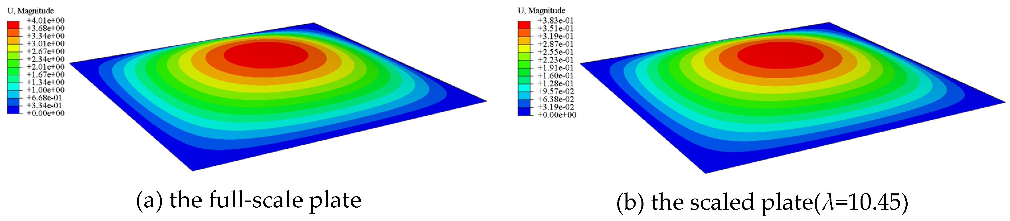
Figure 3.
Comparison of the plate structural responses.
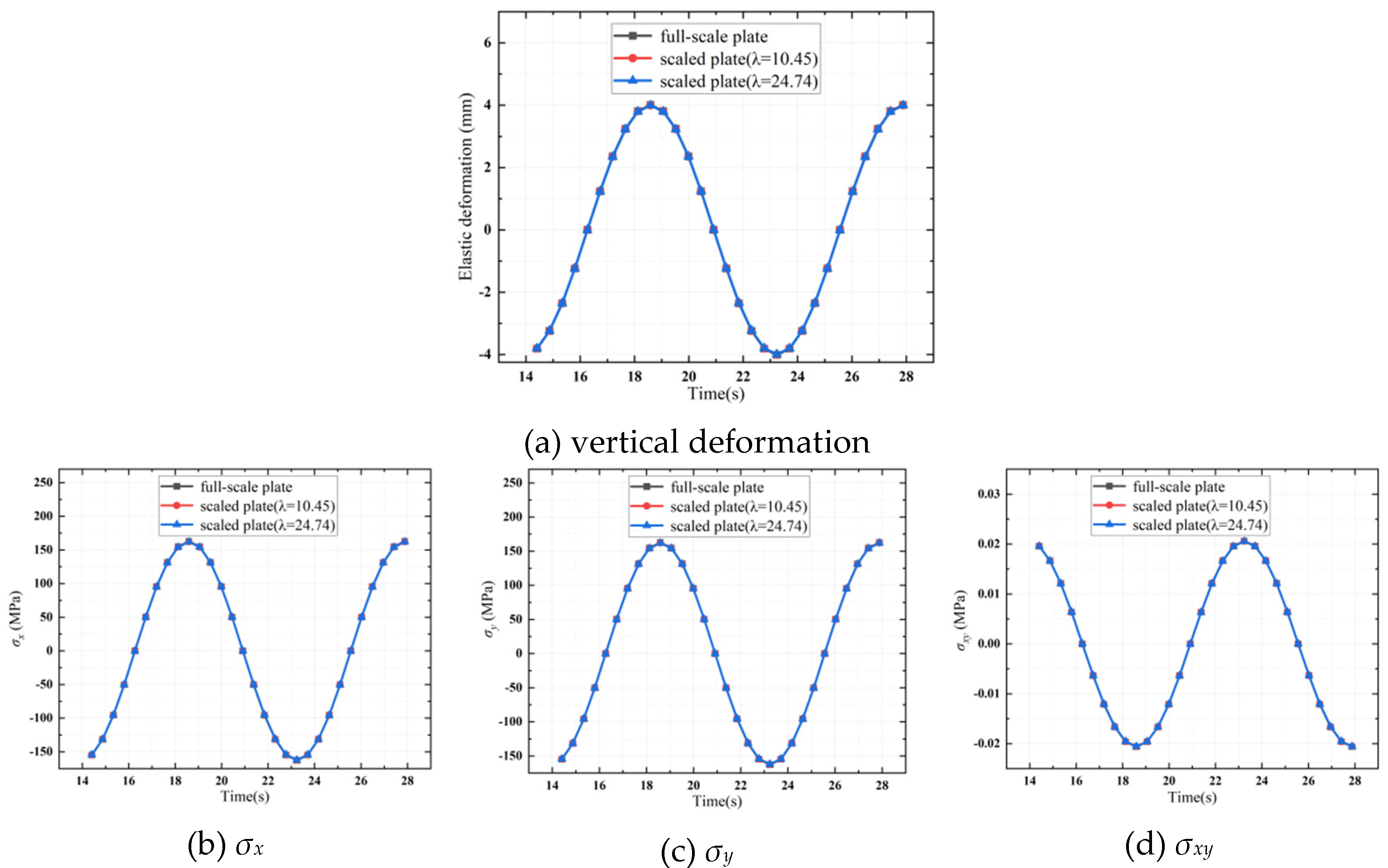
Figure 4.
FE model of the beam component.
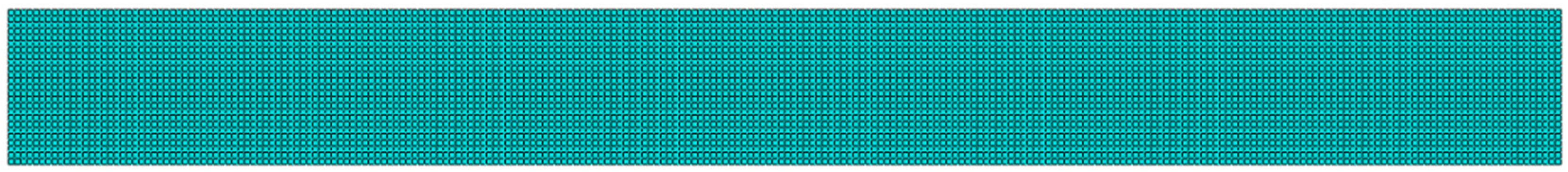
Figure 5.
Deformation contour of the beams.

Figure 6.
Comparison of the structural responses of the beam(λ=10.45).
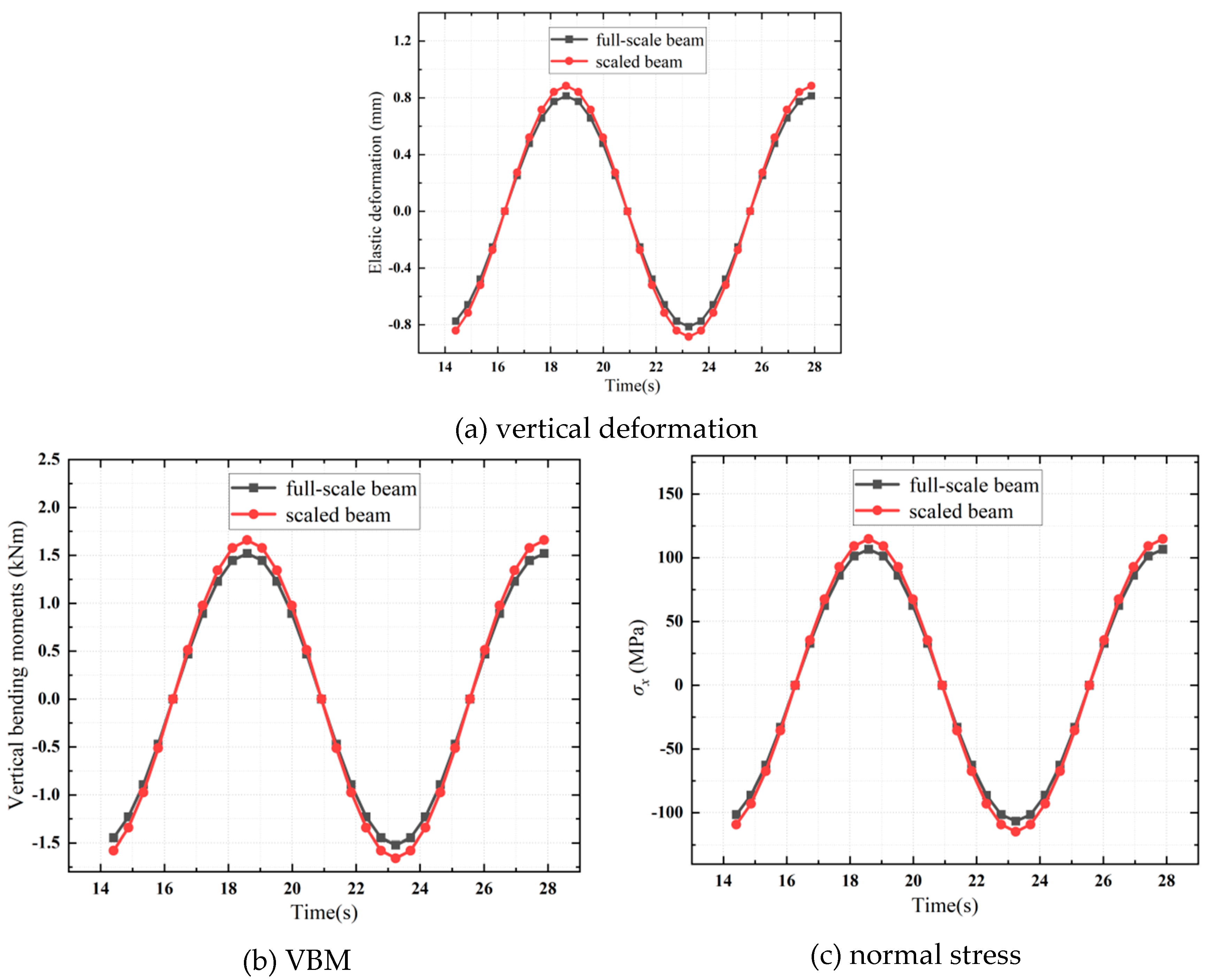
Figure 7.
FE model of a Type IA plate structure.
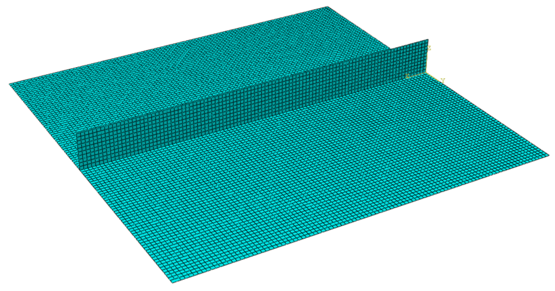
Figure 8.
Deformation contour of the Type IA plate structure.
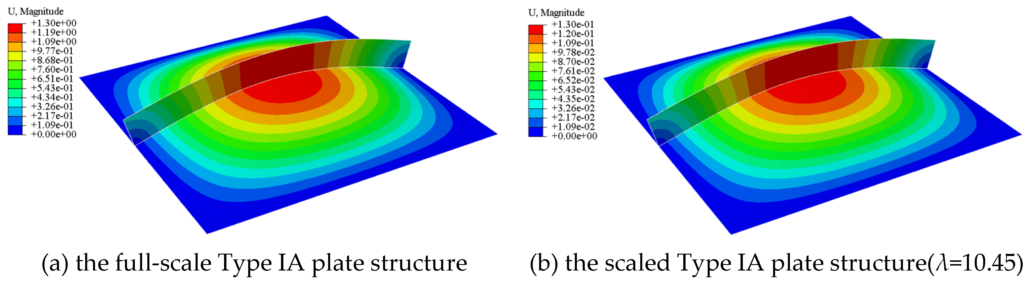
Figure 9.
Comparison of the structural responses of the Type IA plate structure.
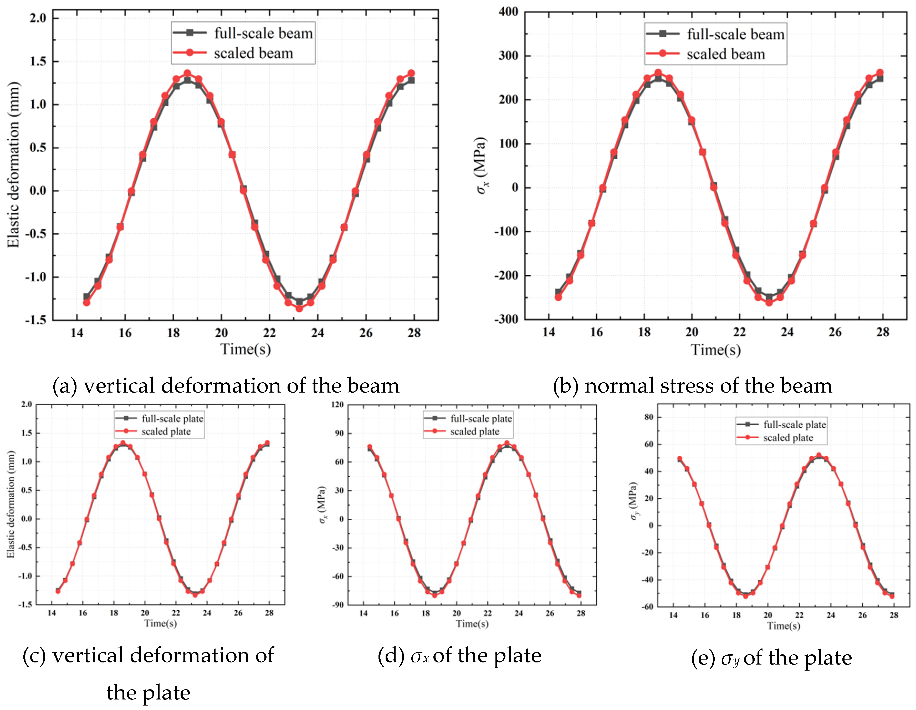
Figure 10.
FE model of a Type IB plate structure.
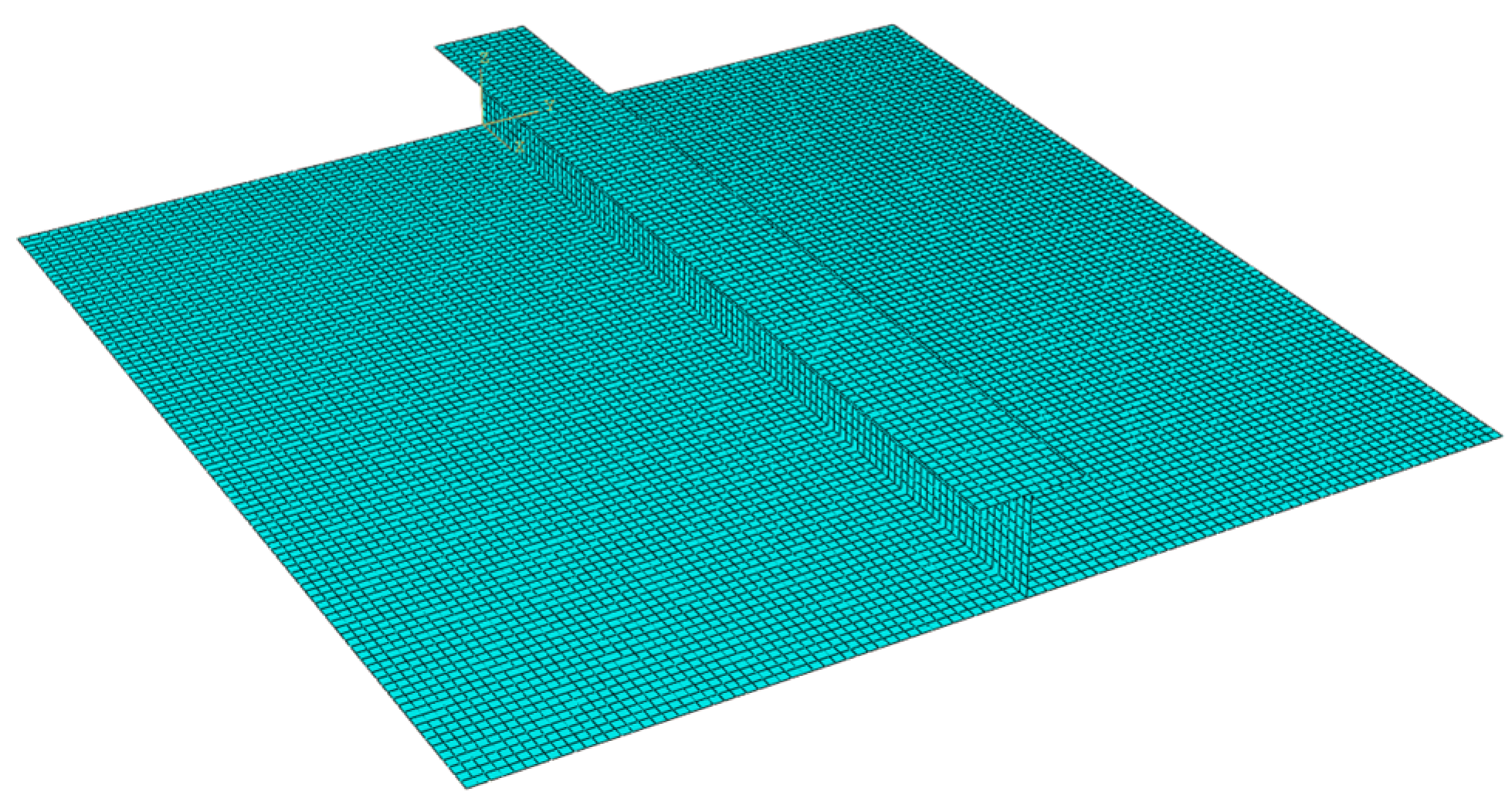
Figure 11.
Deformation contour of the Type IB plate structure.
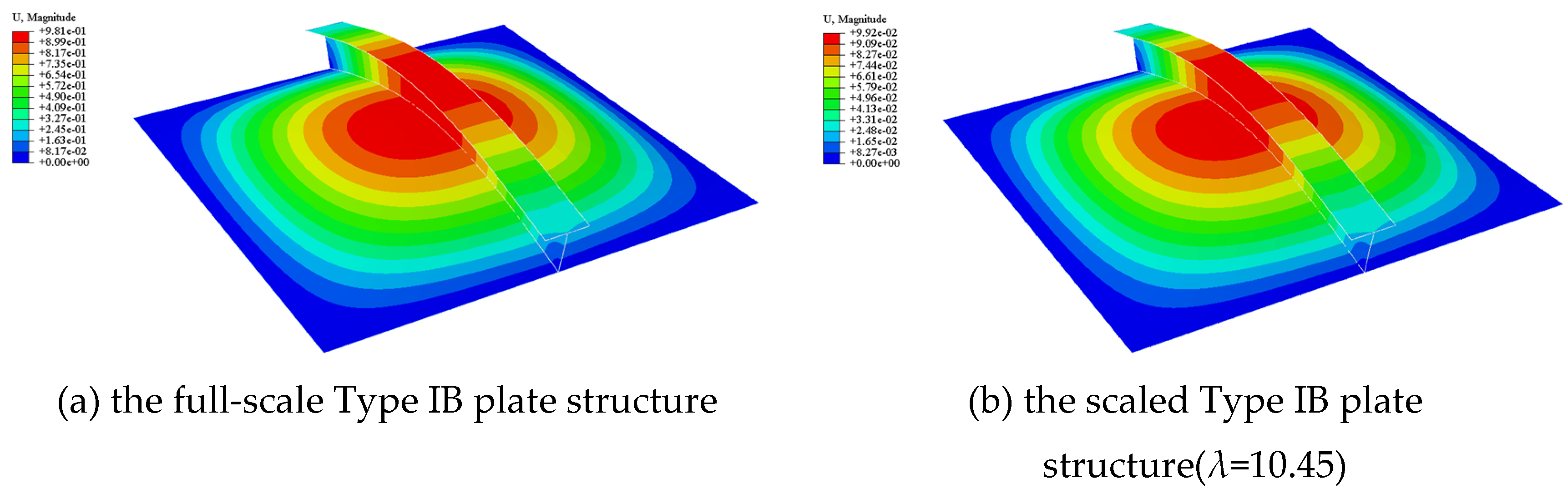
Figure 12.
Comparison of the structural responses of the Type IB plate structure.
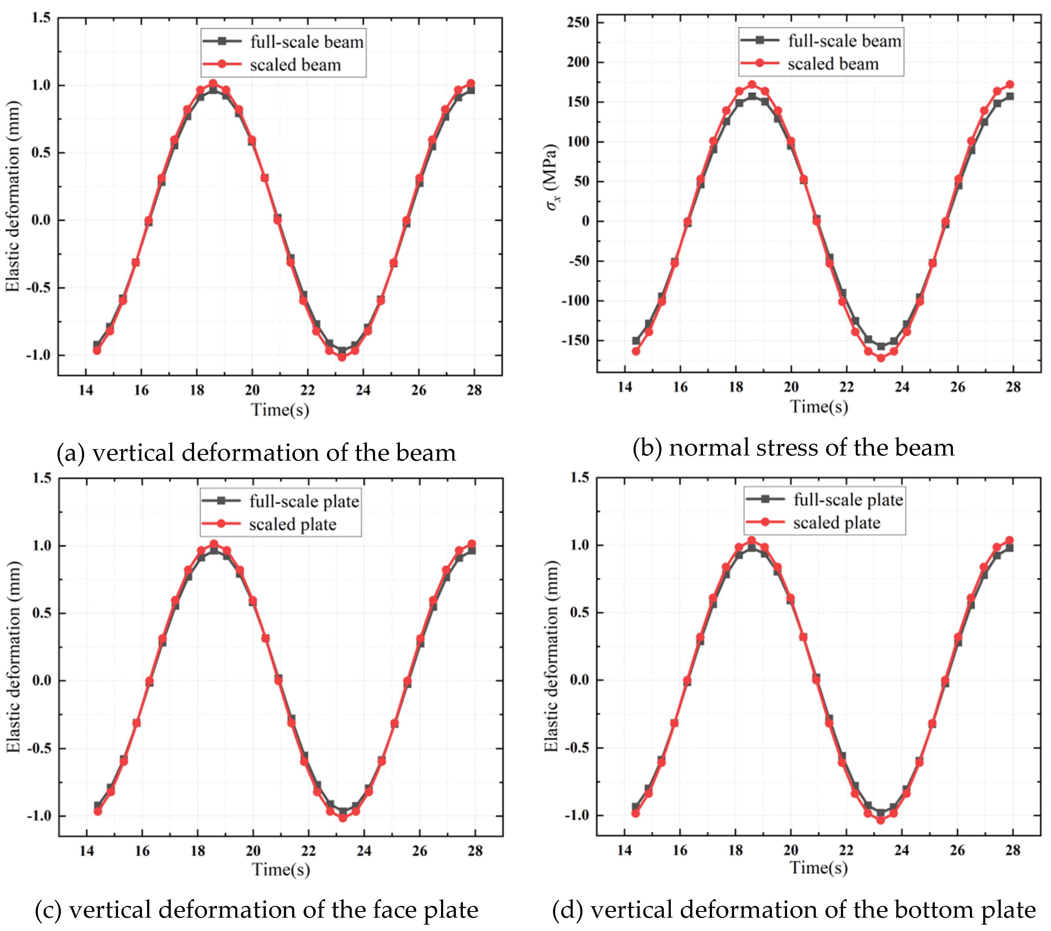
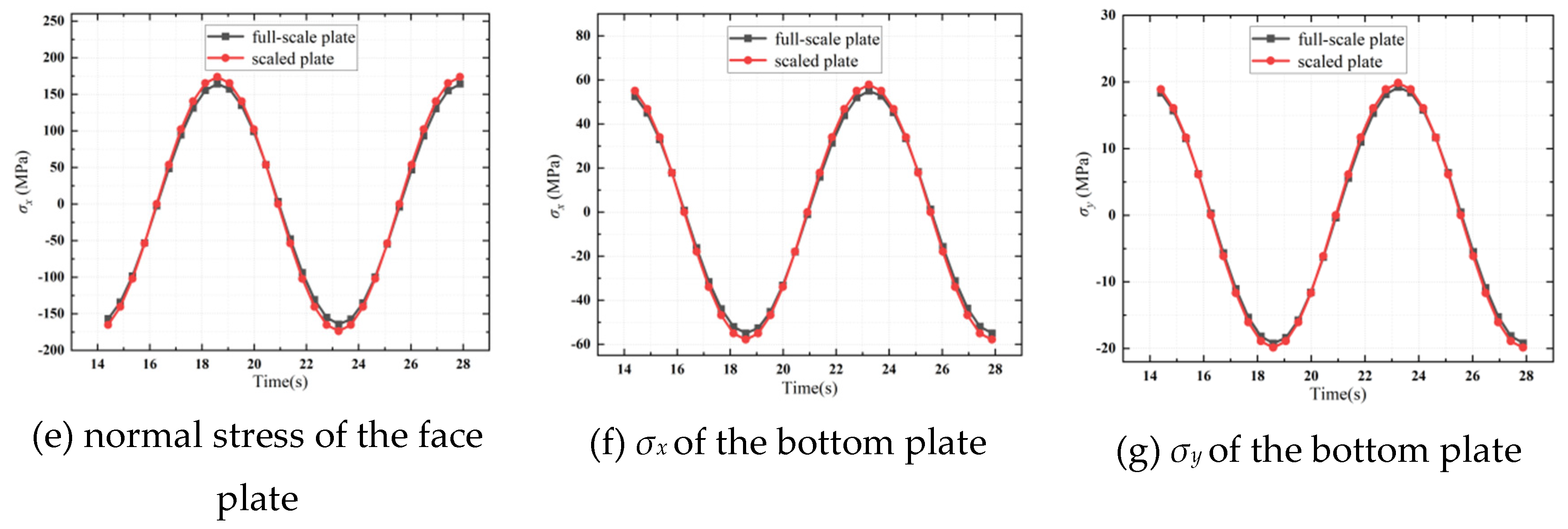
Figure 13.
FE model of a Type IIA plate structure.
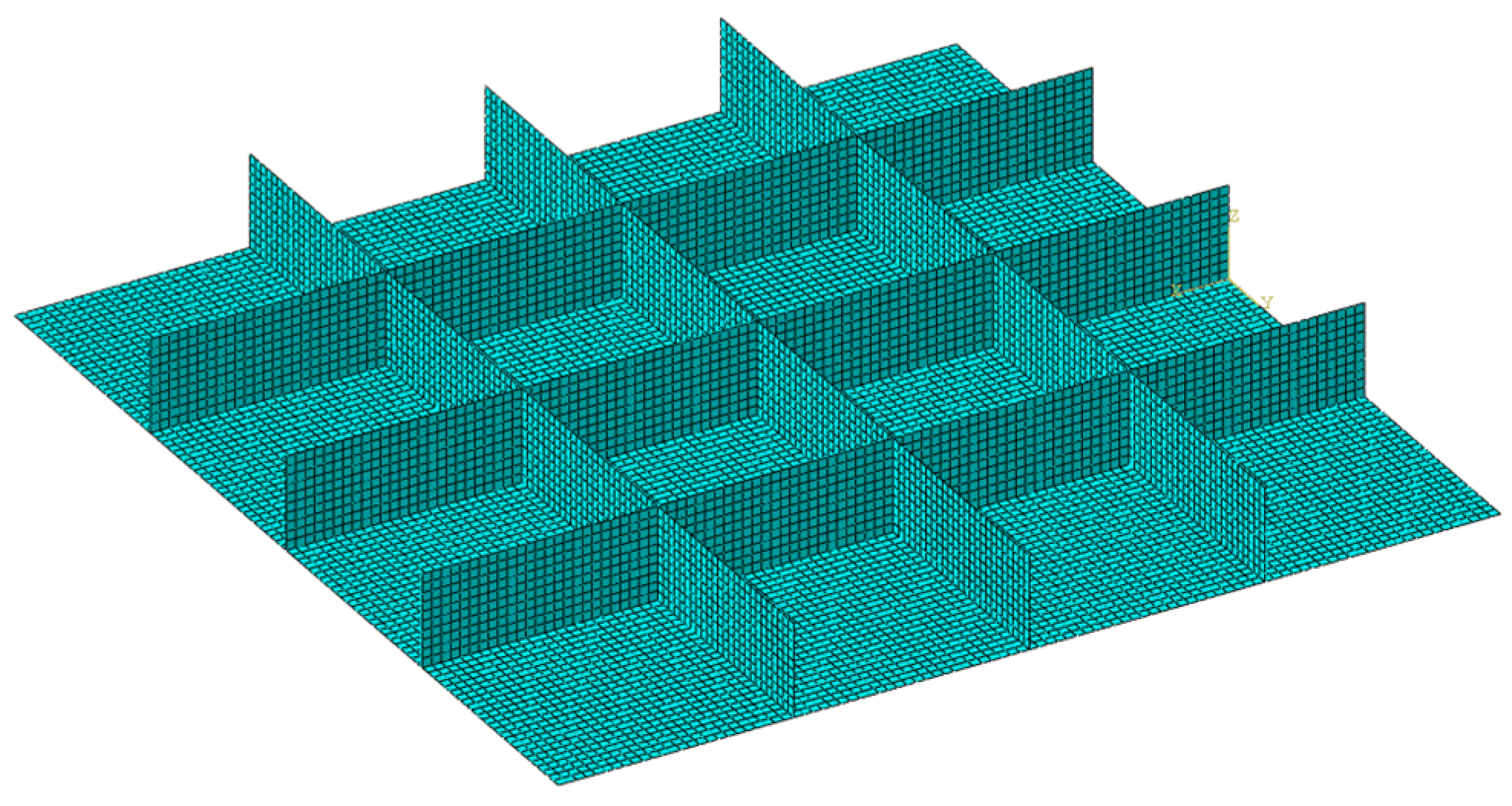
Figure 14.
Deformation contour of the Type IIA plate structure.
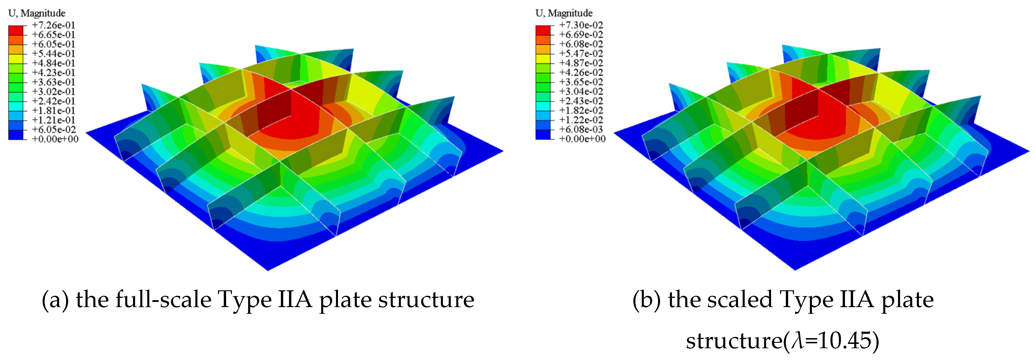
Figure 15.
Comparison of the structural responses of the Type IIA plate structure.
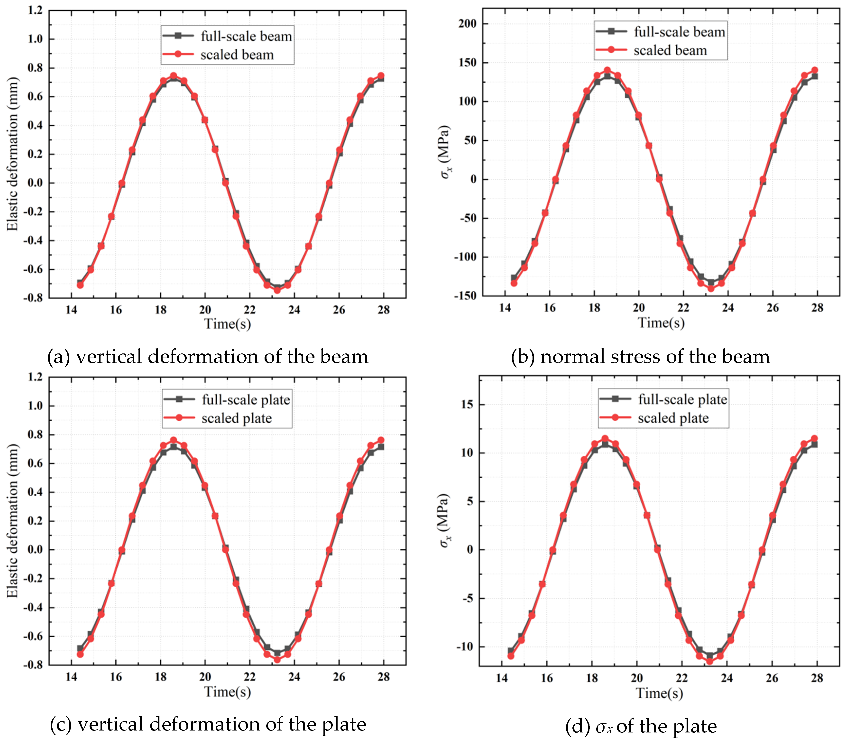
Figure 16.
FE model of a Type IIB plate structure.
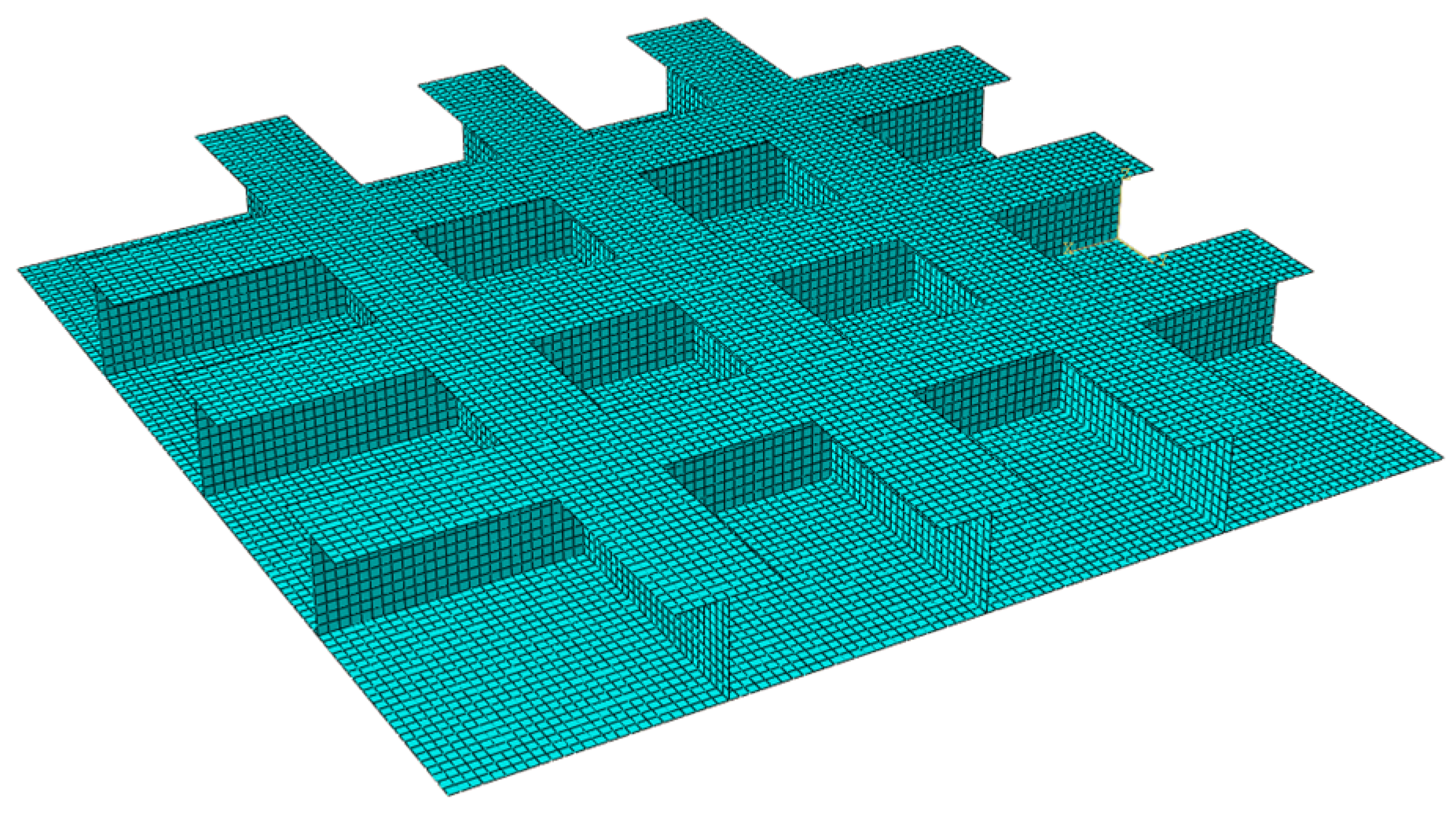
Figure 17.
Deformation contour of the Type IIB plate structure.
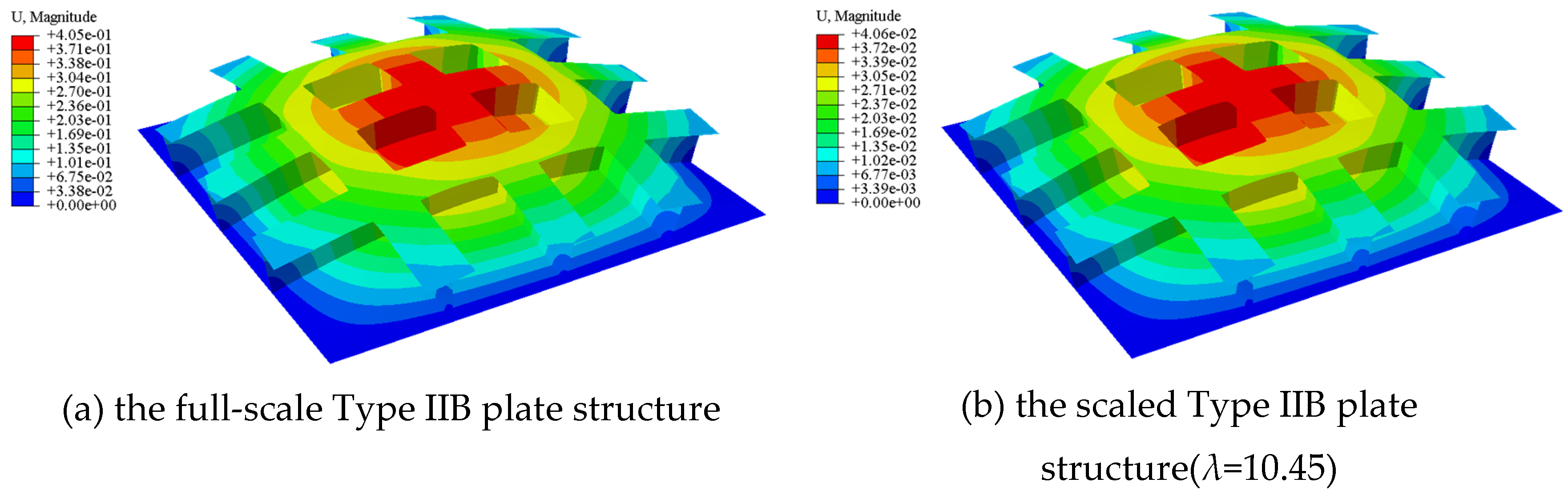
Figure 18.
Comparison of the structural responses of the Type IIB plate structure.
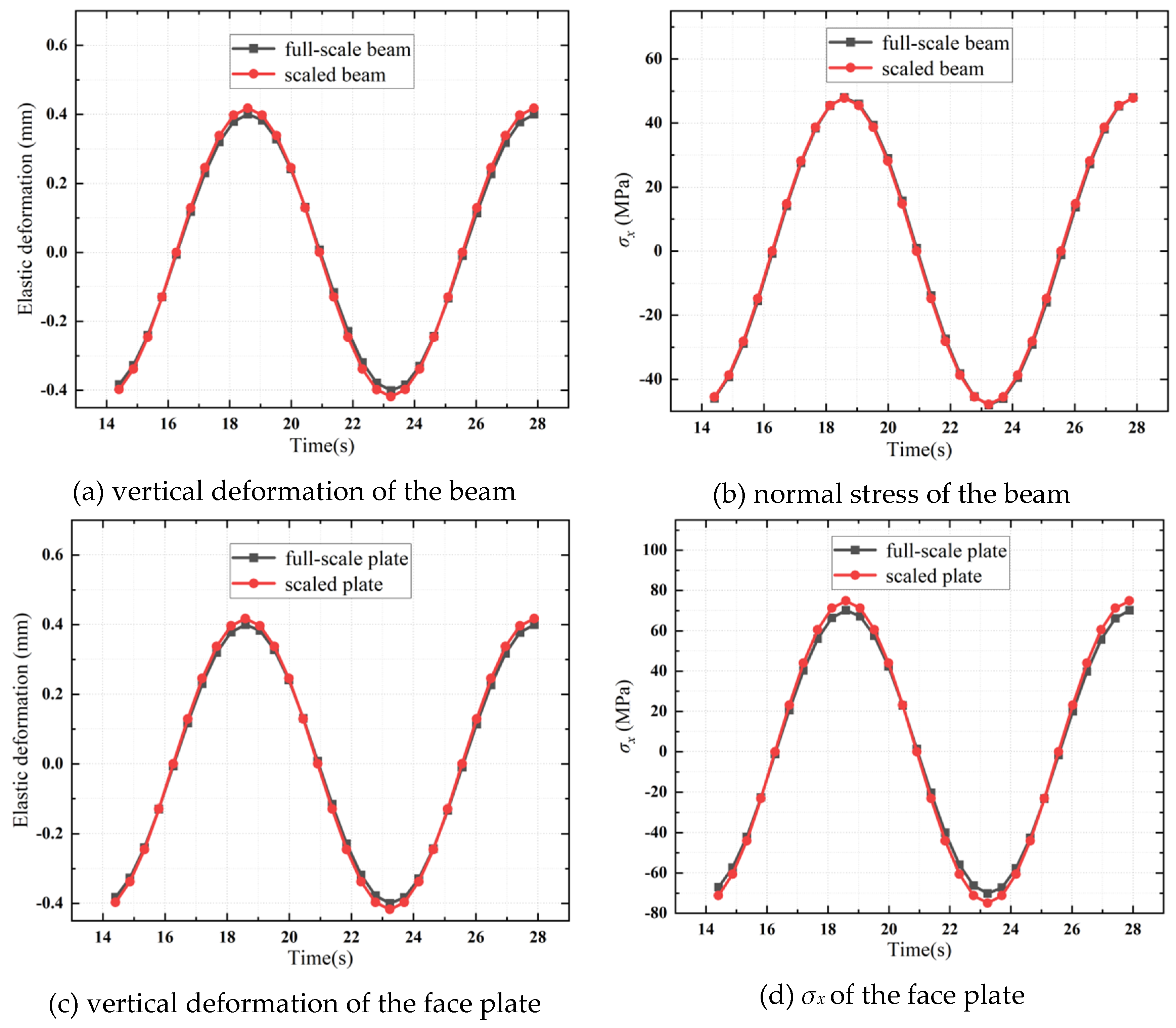
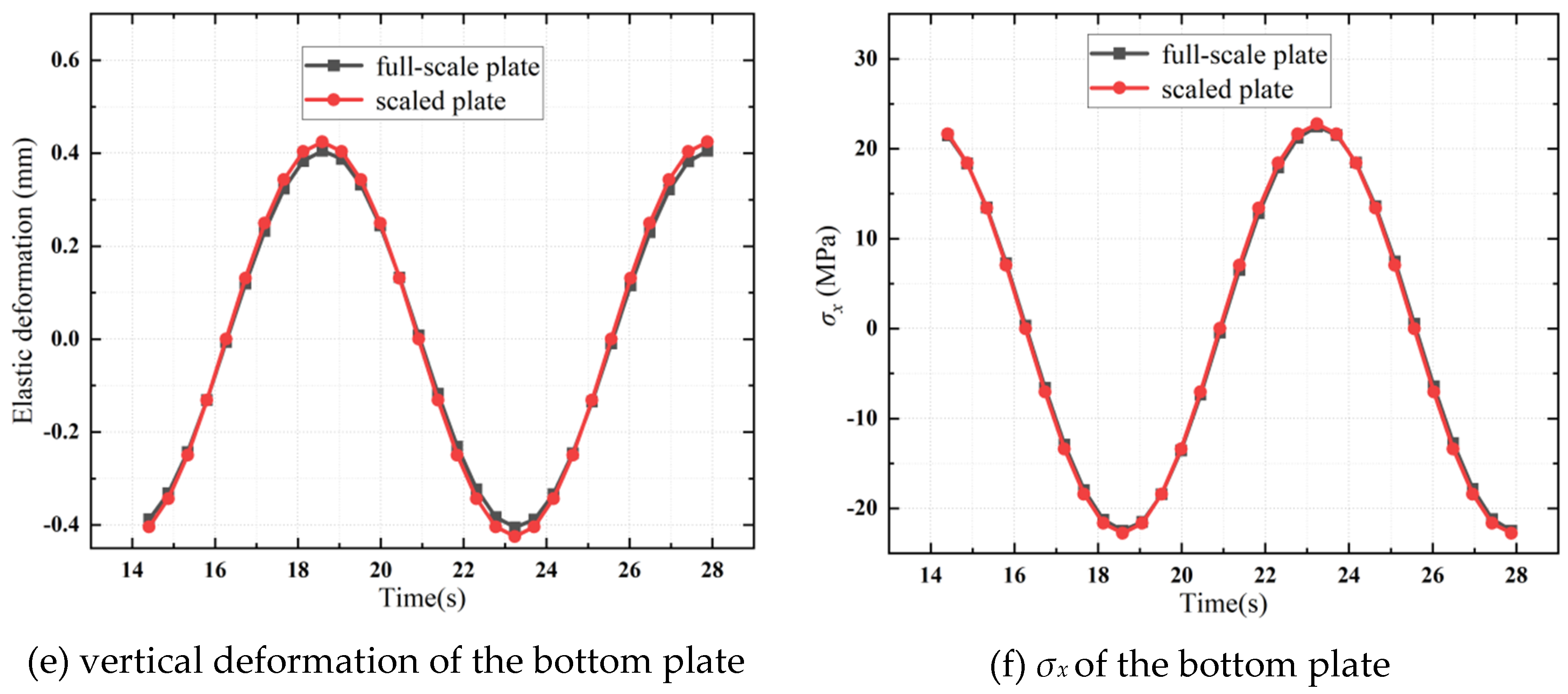
Figure 19.
FE model of a Type III plate structure.
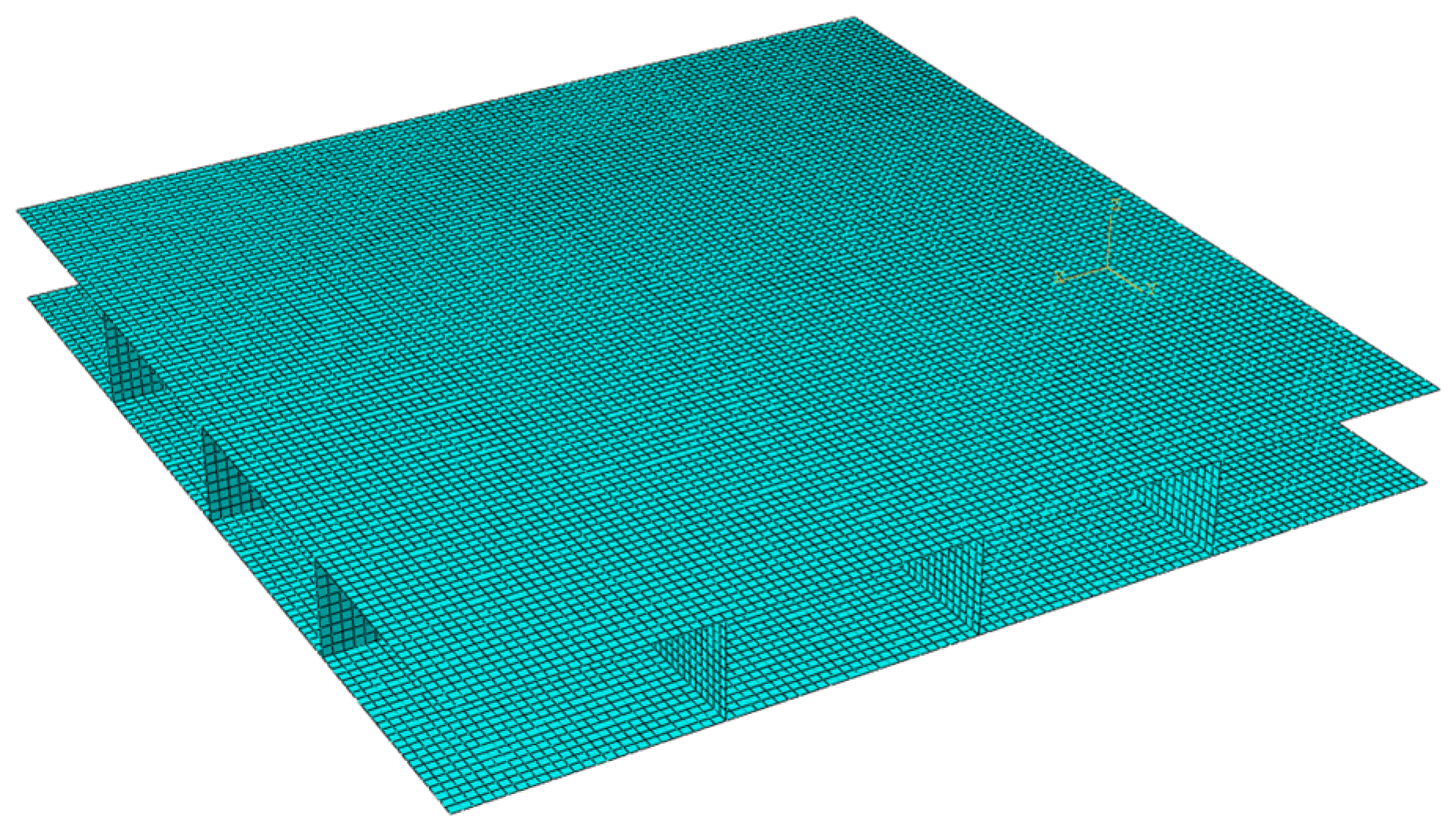
Figure 20.
Deformation contour of the Type III plate structure.
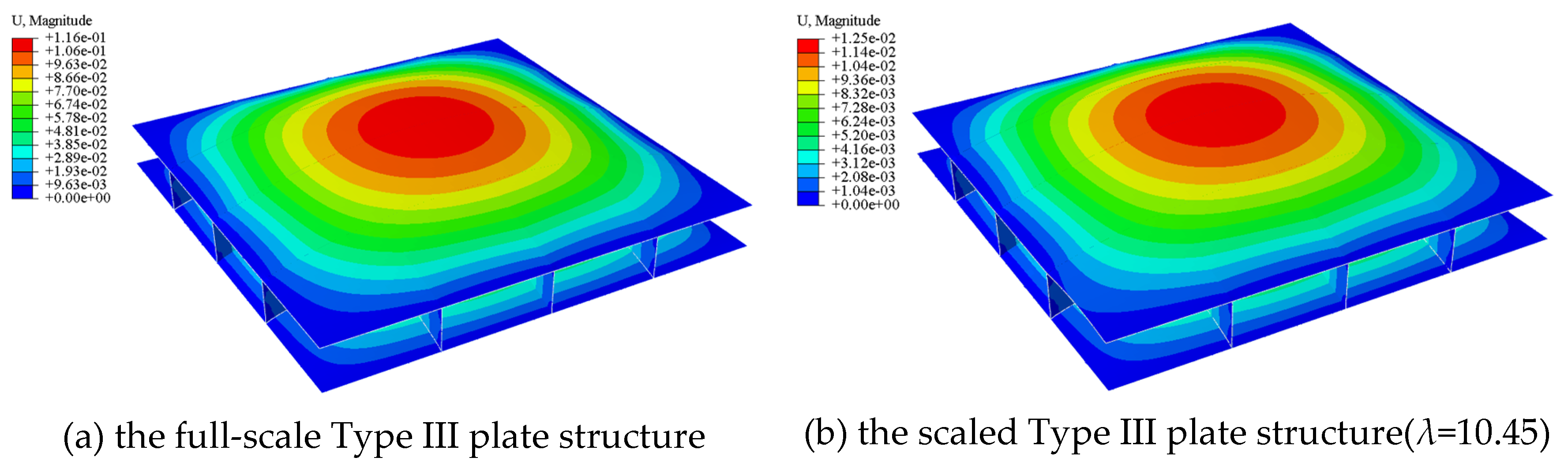
Figure 21.
Comparison of the structural responses of the Type III plate structure.
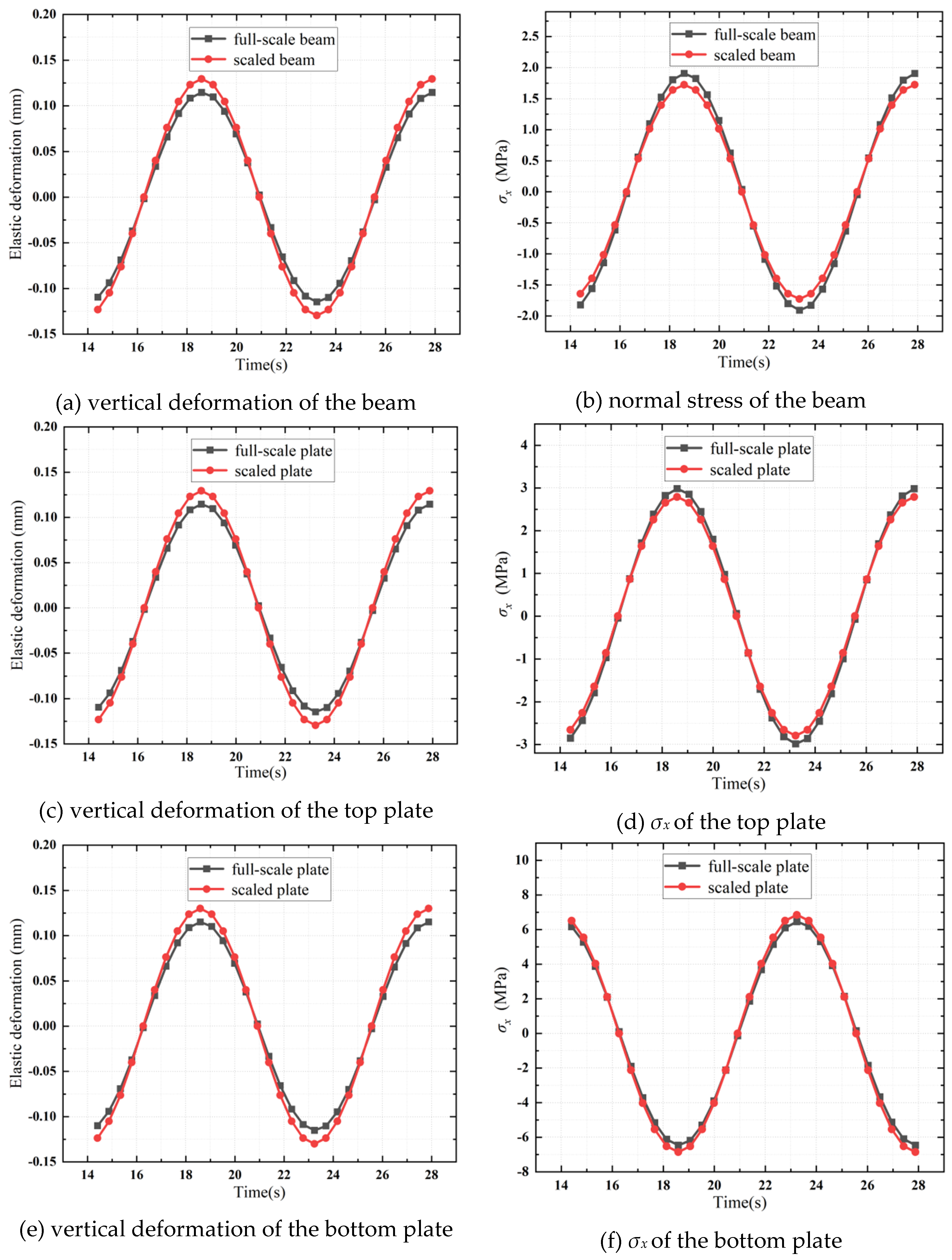

Table 1.
Material parameters and scaling ratios.
| Item | Elastic modulus | Mass density | Poisson’s ratio | Scaling ratio |
| Steel | 211.00GPa | 7800kg/m3 | 0.30 | —— |
| Engineering plastic(ABS) | 2.50GPa | 1040kg/m3 | 0.39 | 10.45 |
| Engineering plastic(PP) | 0.89GPa | 900kg/m3 | 0.42 | 24.74 |
Table 2.
Dimensions of the plate structure components.
| Item | Length(mm) | Width(mm) | Thickness/Height(mm) | Scaling ratio |
| Plate component | 95.69 | 95.69 | 2.87 | 10.45 |
| 40.42 | 40.42 | 1.21 | 24.74 | |
| Beam component | 95.69 | 0.96 | 9.57 | 10.45 |
| 40.42 | 0.40 | 4.04 | 24.74 |
Disclaimer/Publisher’s Note: The statements, opinions and data contained in all publications are solely those of the individual author(s) and contributor(s) and not of MDPI and/or the editor(s). MDPI and/or the editor(s) disclaim responsibility for any injury to people or property resulting from any ideas, methods, instructions or products referred to in the content. |
© 2025 by the authors. Licensee MDPI, Basel, Switzerland. This article is an open access article distributed under the terms and conditions of the Creative Commons Attribution (CC BY) license (http://creativecommons.org/licenses/by/4.0/).
Copyright: This open access article is published under a Creative Commons CC BY 4.0 license, which permit the free download, distribution, and reuse, provided that the author and preprint are cited in any reuse.


