Submitted:
01 January 2025
Posted:
02 January 2025
You are already at the latest version
Abstract
Polyvinylidene fluoride (PVDF) polymer films, renowned for their exceptional piezoelectric, pyroelectric, and ferroelectric properties, offer a versatile platform for the development of cutting-edge micro-scale functional devices, enabling innovative applications in fields ranging from energy harvesting and sensing to medical diagnostics and actuation. This paper offers an in-depth review of the material properties, fabrication methodologies, and characterization of PVDF films. Initially, a comprehensive description of the physical, mechanical, chemical, thermal, electrical, and electromechanical properties is provided. The unique combination of piezoelectric, pyroelectric, and ferroelectric properties, coupled with its excellent chemical resistance and mechanical strength, makes PVDF a highly valuable material for a wide range of applications. Subsequently, the fabrication techniques, phase transitions and achievement methods, their copolymerization and composited that employed to improve and optimize the PVDF properties are elaborated. Enhancing phase transition in PVDF films, especially promoting the high-performance β-phase, can be achieved through various processing techniques, leading to significantly enhanced piezoelectric and pyroelectric properties essential for diverse applications. This concludes the discussion of PVDF material characterization and its associated techniques for thermal, crystal structure, mechanical, electrical, ferroelectric, piezoelectric, electromechanical, and pyroelectric properties, which provide crucial insights into the material properties of PVDF films, directly impacting their performance in applications. By understanding these aspects, researchers and engineers can gain valuable insights into optimizing PVDF-based devices for various applications, including energy harvesting, sensing, and biomedical devices, driving advancements in these fields.
Keywords:
Piezoelectric
; poly(vinylidene fluoride)
; Material properties
; Fabrication
; Characterizations
1. Introduction
Over the past half centry, polymer-based piezoelectric materials [1] have gained significant interest in sensors[2], actuators[3], and energy harvesting[4]. Among these materials, polyvinylidene fluoride (PVDF) and its copolymers have emerged as highly valuable due to their unique combination of properties[5]. PVDF, with the molecular formula (CH₂-CF₂)n, is a non-reactive thermoplastic known for its exceptional thermal, chemical, elastic, piezoelectric, and pyroelectric properties[6]. It is known for maintaining performance across a wide range of demanding environments, making it a versatile material for various advanced applications[7].
PVDF exhibits multiple crystalline phases, including the α-phase, β-phase, γ-phase, and δ-phase, each with distinct properties[8,9]. The α-phase is the most stable and is characterized by non-polar chains, making it less favorable for piezoelectric applications [10]. In contrast, the β-phase, which is polar and has an all-trans configuration, is highly desirable due to its superior piezoelectric properties[11,12]. The γ-phase[13,14] and δ-phase[15] offer intermediate characteristics, with the γ-phase being partially polar and the δ-phase less common and less studied.
The discovery of piezoelectricity by the Curie brothers in 1880 laid the foundation for the development of numerous piezoelectric materials, including PVDF [16] . Although their discovery was not specific to PVDF, it opened the door to research into various materials exhibiting this property. The piezoelectric properties of PVDF were first recognized in the late 1960s, with significant advancements soon following. In 1969, Kawai[17] demonstrated PVDF’s remarkable piezoelectric performance, which was considered superior to other synthetic polymers at that time. This breakthrough spurred extensive research into PVDF and its copolymers, leading to the development of ultrasonic and electroacoustic actuators in the early 1970s [18] .
In 1990s and earlier 2000, droving by U.S. DoD ultrasonic transducer and robostic programs[19,20,21,22] as well as the NASA morphing program [23,24,25,26], the electroactive properties of various PVDF and its copolymers have been studtied intensively. These historical developments have significantly influenced current research trends, particularly the focus on enhancing the β-phase of PVDF [27,28,29], which is associated with superior piezoelectric properties. The ability to control the crystalline phase of PVDF through precise processing techniques, such as mechanical stretching [30], annealing[31], and poling[32], has become a central aspect of modern PVDF research. These techniques are crucial for optimizing the material’s piezoelectric performance and expanding its application scope, which will be explored in detail in later sections.
PVDF's copolymers, such as Poly (vinylidene fluoride-co-hexafluoropropylene) (Poly (VDF-co-HFP))[33], Poly (vinylidene fluoride-co-trifluoroethylene) (Poly (VDF-co-TrFE)) [34], and Poly (vinylidene fluoride-co-chlorotrifluoroethylene) (Poly (VDF-co-CTFE))[35], further enhance its functionality by offering tailored properties for specific uses. These materials combine flexibility, chemical inertness, and a wide frequency response range, making them ideal for demanding environments such as nuclear power[36] aerospace[37], automotive[38], and biomedical[39], industries.
Recent two decades, motivated by U.S. nano initiative, many researchers have made great efforts on developing PVDF based various nano concopiste materirals. [40] Efforts have been focused on developing nanocomposites[40] by introducing high dielectric constant fillers, such as ceramics, semiconductors, metal particles[41], graphene[42], and carbon nanotubes (CNT)[43], into the PVDF matrix. These nanocomposites have significantly expanded the application range of PVDF, particularly in fields where high performance and durability are crucial, such as aerospace [37], automotive[44], construction[45]. The modification of dielectric properties through nanocomposites has enhanced PVDF's applicability in these sectors by improving its mechanical and electrical characteristics.
Despite having lower piezoelectricity compared to commonly used materials like lead zirconate titanate (PZT)[46] , PVDF and its copolymers offer several advantages, including lightweight, low acoustic impedance, ease of fabrication, and chemical resistance. These benefits contribute to PVDF's broad applicability across diverse industries, including electronics [47], radio engineering, civial inferencestructure healthy moninoring, architecture, and pharmaceuticals.
To ensure polyvinylidene fluoride's (PVDF) optimal performance in a range of applications, it is essential to fully define its structural, electrical, and piezoelectric properties. Differential scanning calorimetry (DSC) [48], Raman spectroscopy [49], Fourier transform infrared spectroscopy (FTIR) [50], and X-ray diffraction (XRD)[51] are among the techniques commonly used to analyze the phase conformation and crystalline structure of PVDF. Scanning electron microscopy (SEM) [52], provides information on its shape and microstructure. Piezoelectric and dielectric properties are assessed using a variety of methods, including dynamic [53] and quasi-static testing [54] for piezoelectric coefficients, dielectric constant tests, and piezoresponse force microscopy (PFM) . Together, these techniques maximize PVDF for complex functional applications. In addition, PVDF and its copolymer not only exhibit excellent ferroelectric properties for sensing, actuation, and transduction applications [19,20,23,25,55,56], but are also highly chemical resistant and relatively inert with very low surface energy that little can stick to [57,58,59]. Therefore, PVDF occupied 54% of PV back sheet market share [57]. The low surface energy means that PVDF materials readily can shed dirt and grime and easily clean off any kind of wet or dry dust/soil for transparency surface coading and other future applications.
Although many review papers on PVDF-based materials have been published [2,7,60,61,62,63,64,65,66], there is a gap on comprehensive review on i) various material properties for device engineering and developers, ii) comprehensive review various characterization methosd for materials scientists, and iii) material property modifications for other resreachers.
This Paper is organize as follow: section 2 highlights the major material properties of PVDF polymers including physical, ssmechanical, chemical, thermal, electrical, and electromechanical properties. Section 3 provides a detailed description of fabrication methods, phase transition techniques including stretching, annealing, and poling used for enhancement of PVDF films. Moreover it provide details about copolymerization of PVDF with various material and its important composits. Section 4 provides PVDF films characterization techniques including FTIR, XRD, SEM, DSC etc. At the end, a summary of the overall paper is described.
2. Materials Properties
Material properties have been continuously investigated by researchers to understand and modify them for improved processing and functional performance. This section outlines the key properties of PVDF shown Figure 1 and compares various processing techniques, discussing their relative advantages and disadvantages in optimizing PVDF’s performance. Figures and tables are referenced to support these discussions.
2.1. Physical Properties
PVDF is an opaque resin with an extreme melting point (170-180°C), allowing it to tolerate high temperatures without substantial deterioration. Control over its optical properties, such as transparency, haze, and clarity, is crucial for specific applications. The fundamental cause of limited visible-wavelength transmission and significant mist in PVDF is its rough surfaces. It has a density of about 1.78 g/cm which can increase to 1.97 g/cm³ with orientation of PVDF to 1.97 g/cm³, because of a greater level of crystallinity and higher density of packing. PVDF is characterized by its low weight and remarkable flexibility, which allows it to be readily molded into various shapes.
2.1.1. Crystaline Structure of PVDF
In most cases, the primary factor driving variations in the molecular group's crystal structures is a single bond's internal configurations and rotations [30]. As a semi-crystalline piezoelectric polymer, PVDF’s structure is determined by the configuration of its chains (gauche and trans) and the orientation of adjacent chains. PVDF can crystallize into nine distinct forms, grouped into five primary phases: alpha (α) [10], beta (β) [67,68], gamma (γ)[13,14], and delta (δ)[15], with the ε-phase [69] being less common corresponding to I, II, III, and IV, corresponding. Among these, the α, β, and γ phases are the most significant for practical applications, each offering distinct thermal, electrical, and mechanical properties. These nine crystal forms can be classified into four classes: I, II, III, and IV, corresponding to alpha (α)[70], beta (β) [71,72,73,74], gamma (γ) [75,76], delta (δ) [77] and epsilon (ε) crystal phases [78] . Among these, the α, β, and γ phases are the most significant, while the epsilon (ε) and delta (δ) phases are harder to isolate and are not typically produced through conventional methods. Each crystalline phase has distinct thermal, electrical, and elastic properties, as illustrated in Figure 2.
The α-phase is non-polar and electrically inactive, directly obtained from the molten state, aditionally it is thermodynamically unstable. It features two anti-parallel chains in a TGTG’(Trans-Gauche-Trans-Gauche) configuration[11,79]. In contrast, the β-phase is electroactive, exhibiting strong ferroelectric and piezoelectric behavior[80]. Its all-trans planar zigzag conformation separates most fluorine atoms from hydrogen atoms, resulting in the maximum dipole instant for each unit cell measures 8 ×10-30 cm among all phases. This phase also generates a substantial polarization that occurs naturally due to dipole moment addition[38].
The dipole moments of the γ and δ phases are fewer and weaker compared to the β-phase, but they still possess polar unit cells. The γ-phase, an uncommon state between α and β, has a T3GT3G’ configuration with a higher trans fraction. A crucial difference between the α and δ phases lies in the orientation of dipolar moments within the unit cell: in the δ-phase, they are parallel, whereas in the α-phase, they are antiparallel. The δ-phase, characterized by a TGTG’ (trans-gauche-trans-gauche) structure, can be transformed into β-phase material through the application of a high external electric field, ranging from (100 to 500 MV/m)[11,79].
For many PVDF-based piezoelectric applications, it is essential to achieve high electrical conductivity, dielectric permittivity, low dielectric loss, and high breakdown strength. Optimizing the β-phase significantly improves PVDF's dielectric and piezoelectric properties, making it highly effective for a range of applications.
2.2. Mechanical Properties
Polyvinylidene fluoride (PVDF) is a versatile polymer known for its excellent mechanical properties, making it suitable for a wide range of applications. The mechanical properties of PVDF film includes tensile strength, elongation at break, young's modulus, Yield Strength, and, Impact Strength. Tensile strength is the maximum stress of a material that can withstand before breaking under tensile stress. Its units are pascals (Pa) or megapascals (MPa). A higher tensile strength indicates better resistance to breaking or tearing. PVDF exhibits excellent tensile strength, meaning it can withstand significant pulling forces before breaking. This property is crucial for applications requiring high mechanical stress, such as structural components and protective coatings.
Elongation at break is the maximum amount of strain of a material which can withstand before breaking. It is presented in percentage (%). A higher elongation at break indicates better ductility and flexibility. PVDF also demonstrates good elongation at break, indicating its flexibility and ability to deform under stress without fracturing. This characteristic makes it suitable for applications that involve bending or flexing. Young's modulus is another mechanical propertity, which is a measurement of the stiffness of a material. It represents the ratio of stress to strain in the elastic region which units are pascals (Pa) or gigapascals (GPa). A higher young's modulus indicates a stiffer material. Yield strength is the stress at which a material begins to deform plastically. Pascals (Pa) or Megapascals (MPa) are the units of yield strength. A higher yield strength indicates better resistance to plastic deformation.
Impact Strength is the ability of a material to resist sudden impact forces. Its unit is joules per meter (J/m) or foot-pound per inch (ft-lb/in). A higher impact strength indicates better resistance to shock and impact loads. PVDF possesses excellent impact resistance, making it capable of withstanding sudden shocks and impacts. This property is particularly valuable in applications where the material may be subjected to accidental drops or collisions. PVDF exhibits good fatigue resistance, which is meaning it can withstand repeated cycles of stress without experiencing significant degradation. This property is essential for applications that involve continuous or cyclic loading. PVDF also demonstrates excellent creep resistance, indicating its ability to maintain its shape and dimensions over time under constant load. This property is crucial for applications requiring long-term dimensional stability. Besides all these properties PVDF has a high melting point and excellent thermal stability, allowing it to withstand high temperatures without significant degradation. This property makes it suitable for applications in harsh environments. Specific equations for calculating these mechanical properties can be complex and often require experimental data, some fundamental concepts can be expressed mathematically I equations (1-2).
Stress (σ) = F/A(Pa),
Strain (ε) = ΔL/L₀
Where F symbolize the applied force (Newton), A is the cross-sectional area (m²), ΔL represents change in length (m),and L₀ is the original length (m). The factors that influence mechanical properties of PVDF includes molecular weight, crystallinity, processing techniques, and post-processing treatments. Higher molecular weight, and crystallinity improves mechanical properties like tensile strength and modulus. Processing techniques like extrusion and molding can influence the final properties. The post processing techniques like stretching and annealing can further enhance the mechanical properties. PVDF is frequently employed to coat the outside surfaces of buildings since it exhibits little to no degradation in mechanical qualities over several decades of outdoor use. Among traditional crystalline polymers, PVDF is particularly notable for its mechanical qualities. It has the greatest impact strength, a significant coefficient of curing, and is ranked second after polyoxymethylene on the basis of the degree of hardness, tensile strength, compressive stress, and flexural stress stiffness[62].The various properties of PVDF are provided in Table 1.
2.3. Chemical Properties
A substance's solubility is affected by its chemical and physical characteristics, as well as by external variables like temperature, pressure, and the presence of other chemicals in the solution. PVDF, an organic polymer, follows the "like-dissolves-like" rule, with polarity playing a key role. PVDF is soluble in a few organic solvents, such as dimethylformamide (DMF), dimethyl sulfoxide (DMSO), N-methyl pyrrolidone (NMP), and dimethylacetamide (DMAc), but is generally insoluble in aliphatic compounds, aromatic compounds, chlorine solutions, alcohols, strong acids, halogens, and basic solutions. PVDF copolymers tend to be slightly more soluble due to lower crystallinity[36]. PVDF is recognized for its excellent chemical resistance, making it suitable for harsh environments. However, it reacts negatively with many ketones, esters, and strong alkalis[83]. Over time, the properties of PVDF are weakened by exposure to strong alkaline solutions [84].
For example, NaOH can cause discoloration and brittleness in PVDF membranes. The degradation mechanism involves dehydrofluorination, leading to the formation of carbon-carbon double bonds and polymer chain weakening [85]. Studies have shown that the addition of stress and strain accelerates this degradation process. When exposed to NaOH, PVDF's mechanical strength diminishes, confirmed by various tests and spectroscopic analyses [86]. In addition to NaOH, PVDF's stability has been tested with chemicals like sodium hypochlorite (NaOCl) and potassium hydroxide (KOH) [87]. These studies reveal structural modifications and increased hydrophilicity, resulting in weaker and more flexible membranes after prolonged exposure. Overall, PVDF demonstrates outstanding chemical stability and durability, but careful consideration is required when used with strong alkaline solutions to prevent degradation. Table 2 shows the chemical properties of PVDF.
2.4. Thermal Properties
Thermal stability in polymers refers to their ability to resist heat and maintain properties like strength, durability, and flexibility. Two key parameters influence PVDF's thermal stability: the glass transition temperature (Tg) and the melting temperature (Tm). PVDF has a Tg between -20°C and 60°C, making it a rubbery polymer above 0°C. Melting temperatures are between 160°C and 190°C, which is depending processing and phase conditions. Every phase of PVDF have comparable melting temperatures, with slight variations in Tm can indicate various crystalline phases. PVDF has excellent thermal stability, withstanding temperatures ranging from -30 to 170°C. Its temperature of thermal degradation also remains constant, ranging from 400 to 450 °C, regardless of the crystalline phase, quantity of crystallinity, and manufacturing technique. Most data suggest that the Curie temperature (Tc) of PVDF, where it loses spontaneous polarization, is between 195°C and 197°C. PVDF's low thermal conductivity makes it ideal for insulation, and its low coefficient of linear thermal expansion ensures minimal dimensional changes under different temperatures [88].
2.5. The Electroactive Properties of the PVDF
PVDF is notable for its exceptional piezoelectricity, which refers to its capability to produce an electric charge when a mechanical stress or force appled, as well as generating mechanical stress whenever an electrical filed is applied. Figure 3 shows a Heckman diagram representing the interrelationship between the mechanical, thermal and electrical properties of materials.
2.5.1. Ferroelectric Effect
PVDF's ferroelectricity is caused by dipole moments, shown in Figure 4, inside its molecular structure, which are mainly induced by strongly electronegative fluorine atoms as shown in the β-phase in Figure 2(b). These dipoles align in response to an electric field, allowing the material to create a hysteresis loop, which is essential for ferroelectric activity. PVDF's ferroelectric properties, discovered in 1974[90], enhance its piezoelectricity by allowing it to keep polarization long after the electric field is removed. However, as-manufactured PVDF films, particularly those formed from melt or solution, lack ferroelectricity because the dipole moments cancel due to their crystal structure. Additional approaches, such as mechanical stretching or the usage of copolymers like P(VDF-TrFE), are necessary to induce ferroelectricity [91]. These techniques enhance dipole alignment, resulting in ferroelectric behavior. PVDF demonstrate a shift in phase and transition temperature with an applied electric field, similar to ferromagnetic materials [92]. When heated over the Tc, the material transitions from the ferroelectric β-phase to the paraelectric α-phase. Below this temperature, PVDF maintains spontaneous polarization [93].
2.5.1.1. Dielectric Properties
The energy dissipation in PVDF, also known as the dielectric loss (tanδ)[20]. It describes how energy is lost in dielectric materials under an electric field. A loss factor is defined as
Where is the real part of the dielectric constant, and ε′′ is the imaginary part representing energy loss. For PVDF, the dielectric loss is influenced by frequency and nanofiller presence, typically ranging from 0.04 to 0.11 depending on the sample [94].
2.5.1.2. Piezoelectric EFFECT
Expression "piezoelectricity" refers to a property of a material to convert intrinsic elasticity into dielectric energy if it is exposed to an external pressure[95,96,97]. In PVDF, this effect can be quantified through several important constants such as the piezoelectric strain constant (dij), the piezoelectric voltage constant (gij), and the electromechanical coupling coefficient (kij)[98], which together characterize the efficiency and sensitivity of PVDF's piezoelectric response to mechanical stress/deformation. The piezoelectric charge constant (dij) is a key parameter that describes the relation between mechanical stress and electric polarization.
Direct Piezoelectric Effect: A piezoelectric material produces an electric charge on its surface when mechanical force is applied to it. This charge may be gathered and used to a number of things, including sensors, transducers, and and energy harvesters [99,100,101].
where D is the dielectric displacement in C/m2 or N/mV. is the stress vector in N/m2 and d the piezoelectric coefficient C/N or m/V, is the dielectric permittivity in F/m or N/V2. is the applied electric field in V/ m.
Inverse Piezoelectric Effect: A piezoelectric material undergoes deformation or changes in shape when an electric field is appled to it. Utilizing the material's reaction to an applied voltage to provide precise control is how this quality is exploited in devices like piezoelectric actuators[102,103,104]. The inverse piezoelectric effect serves as the basis for the electromechanical actuator of electro-deformation. Figure 5 demonstrates a schematic illustration of the piezoelectric phenomenon [105]. Where is the strain, sE is compliance matrix coefficient, d is piezoelectric coefficient, and E is electric field.
The piezoelectric coefficient, dielectric permittivity, and elastic compliance matrices aregiven in equarion (6), where the 3-direction is along the poling direction and the 1-direction is along the stretching.
Figure 5 shows a schematic representation of direction index of electromechanical constants in poled piezoelectric in various modes including longitudinal, converse, and shear direction[61].
Piezoelectric Strain Const.ant (dij): The general relationship between the applied stress (σ) and the electric polarization (P) is given by[66]:
In this equation, d is the piezoelectric strain constant, which describes the amount of electric charge is generated per unit of applied mechanical stress[106].
The piezoelectric coefficients (dij) form a matrix that expresses the behavior of the material in different directions. The matrix form for the piezoelectric coefficients is represented as [107].
Where d31, d32 and d33 represent the piezoelectric strain constants in different directions, while d24 and d15 are shear piezoelectric strain constants.
For PVDF, the relationship is expressed as[108]:
Where Qi is the electrical charge generated, Ai is the area over which the charge is measured, Fj is the mechanical force applied, and Aj is the area over which the force is applied. In PVDF, the most commonly measured coefficient is d33 , which describes the charge generated along the thickness of the material when subjected to stress in the same direction[12].
Where Qsample is the generated charge, and Fdynamic is the applied force.
Another typical piezoelectric coefficient is the transverse mode (d31), where mechanical stress is applied at a right angle to the polarization direction.
Piezoelectric Voltage Constant (gij): The piezoelectric voltage constant (g) represents the electric field generated per unit of applied mechanical stress [109]. This is crucial in sensing and energy harvesting applications. The equation for the electric field E generated by an applied stress σ is:
Simplifying this relationship with mechanical stress σ and the Young’s modulus Y[109]:
Where V is the generated voltage, epsilonϵ is the strain, Y is Young's modulus of the material, and L is the length of the material. Experimental values for PVDF films have shown voltage responses ranging from 5 to 30 mV during mechanical stretching.
The relationship between the piezoelectric charge (d) and voltage (g) coefficients is given by [109]:
The dielectric constant of piezoelectric materials is another key parameter that determines how a material stores electrical energy in the presence of an electric field.
The piezoelectric d31 coefficient of PVDF can be calculated by .
Where is the vacuum permittivity with value of and is the relative permittivity of the material.
Electromechanical Coupling Coefficient (kij): The electromechanical coupling coefficient is used to directly assess the efficiency of energy conversion in materials [110]. Consequently, the coupling factor k is defined as a direct or inverse function of the piezoelectric effect, based on the following relationships:
Here, represents mechanical compliance at a constant electric field, and is the dielectric constant.
2.5.4. Pyroelectric Effect
While the piezoelectric effect involves generating charge in response to applied mechanical stress, the pyroelectric effect involves generating charge due to changes in temperature [111,112]. This effect arises from the spontaneous polarization in PVDF’s molecular structure, primarily in its β-phase, where dipoles align along the polymer chains. When the temperature changes, the polarization also changes, resulting in a measurable surface electric charge. This property is especially useful in applications such as infrared sensors, thermal detectors, and energy harvesting devices [113]. Pyroelectricity in PVDF is often enhanced by processes like stretching, which align the dipoles more effectively, increasing the material's sensitivity to temperature variations. The pyroelectric effect and its different steps are shown in Figure 6.
The pyroelectric coefficient, denoted as p3, represents the charge generated per unit area per degree of temperature change and can be expressed as equation (17).
Where P is the polarization, T is the temperature, d33 is the piezoelectric constant, αs is the thermal expansion coefficient, and represents the rate of temperature change.
3. Enhancement of PVDF Properties Through Optimized Preparation Methods
The structure of PVDF directly influences its characteristics. For example, in certain fields, PVDF is used for different purposes, such as film, fiber or complex shapes with different thicknesses to meet the needs of different industries. The dielectric permittivity and electrical conductivity of PVDF are known to rise with an increase in the β-phase content. To improve other properties of PVDF, it can be formed into two fibers or layers. Morover, PVDF with piezoelectric characteristics can be achieved through straightforward material modifications, such as phase transitions [114], or by using advanced processing technologies [64]. In addition, achieving the desired properties involves the use of PVDF copolymers[115]. Figure 7 shows different methods of improving PVDF properties. Many researchers have also improved various properties of PVDF, especially piezoelectricity, by blending with polymers or adding fillers [116]. In addition, different grades of PVDF, such as high molecular weight PVDF or low molecular weight PVDF, play a crucial role in achieving certain goals.
3.1. PVDF Film Fabrication Methods
The manufacturing process plays a crucial role in shaping PVDF's diverse features, including its superior dielectric and piezoelectric properties. PVDF can be fabricated using a variety of techniques to create a two- or β-phase material. The hot pressing method, 3D printing, spin coating, electrospinning, and solution casting, are examples of common techniques. These methods frequently result in Langmuir–Blodgett films, which are nanostructured solid films formed at the liquid–gas interface. Solvent casting techniques, like electrospinning, solvent evaporation, and spin coating, however, have been receiving increased attention as a result of the need for films with nanoscale thicknesses in numerous applications.
3.1.1. Solution Casting
One common method for producing PVDF and its copolymer-based films is solution casting as shown in Figure 8, which can obtain excellent films with better mechanical, optical, and physical characteristics through the unform in-plane distributions. Certain organic solvents, including DMF[117], methyl ethyl ketone (MEK) [118], dimethyl sulfoxide (DMSO)[119], acetone [120], N,N-dimethylacetamide (DMAc)[121] and 1, 3-dioxolane (DXL) [122], can dissolve PVDF and its copolymers.
The dissolution process usually takes place at room temperature but sometimes, require higher temperature (<70°C) [123]. One popular technique for enhancing dissolution is using ultrasonication aid mixing technology. In most cases, the ultrasonication operation time is less than 30 minutes, but it can vary case by case and range from a few minutes to three hours[121]. Stirring, as compared to ultrasonication, is typically done for longer than 30 minutes. After evaporation, the fully mixed PVDF/organic solution is placed over an Al substrate or glass to create the first films [121]. Evaporation can occur in vacuum chambers or in the air, with temperatures ranging between 50°C and 120°C and glass [123]. A schematic representation of the solution casting technique PVDFpreparation process is shown in Figure 8.
3.1.2. Solution Coating
Another commonly employed method for creating composite membranes is solution coating. This method, illustrated in Figure 9, creates composite membranes by applying a thin layer of chosen later polymer solution over a porous substrate. Since a selective coating layer can regulate them, care should be taken beforehand to ensure that the substrate's degree of porosity is larger than the membrane resistance. A low boiling point solvent, which is insoluble with the coating solvent and can lessen invasion, is applied to the substrate prior to the coating process. To create a coated membrane, the solvent is further evaporated. Solution coating's primary benefits are its ease of fabrication—it can produce homogenous coatings over huge areas at low temperatures [124,125,126,127].
3.1.3. Spin Coating
Spin-coating method shown in Figure 10, is used to prepare thin film, it is a cost-effective and time-efficient method for processing uniform polymer films from a dilute solution on a planar substrate [31]. This method is suitable for producing smooth polymer coatings for microelectronic applications. Researchers have successfully prepared nanoscale films of crystalline phase PVDF using this technique. Key factors like humidity and rotation speed can measure the surface roughness and phase content of thin films[128]. Additionally, the thickness of the films depends on the solvent solution's properties and the spin speed. However, the thin films are pure non-poled alpha phases of PVDF, necessitating further polarization for piezoelectric response [115,129].
3.1.4. Hot Pressing Method
The fabrication of PVDF films using hot pressing begins with the preparation of PVDF powder or pellets. Figure 11(a) shows the hot pressing method of PVDF while Figure 11(b) shows the example of hot pressing equipment. The material is melted under controlled conditions, typically at temperatures ranging from 150°C to over 200°C[130], ensuring complete melting without decomposition. High pressures, often between 5 and 40 MPa[131] are applied to compress the material, eliminating voids and enhancing density. Following the application of heat and pressure, the films are cooled in a controlled manner, solidifying the polymer into the desired crystalline phases. Additional treatments such as stretching or electrical poling can be applied to optimize the material's piezoelectric properties[130].
Hot pressing is recognized for its ability to improve the crystalline phases of PVDF, especially the transition from the α-phase to the β-phase, which is critical for piezoelectric applications [132]. The technique is particularly advantageous for its ability to produce dense films with high β-phase content, superior dielectric properties, and improved mechanical performance. For instance, studies have demonstrated that varying the hot press temperature influences the crystallite size of PVDF films. At temperatures around 170°C, the crystallite size significantly increases, enhancing the β-phase content and resulting in films with superior piezoelectric and dielectric properties. Specifically, crystallite size has been observed to grow from 7.2 nm to 20.54 nm with increased pressing temperature [133].
Hot-pressed PVDF films also exhibit exceptional dielectric properties. Films processed at 150°C have been reported to achieve high energy densities (19.24 J/cm³) coupled with efficiencies of 68.99%. Additionally, their breakdown strength of 1189 kV/cm and dielectric loss as low as 0.04 make them highly suitable for high-performance energy storage applicationss [134]. The temperature and pressure applied during hot pressing play a critical role in determining the crystallinity and phase composition of the films. Rapid cooling post-pressing has been shown to promote β-phase retention, further enhancing the material’s functional properties. Comparative studies highlight the superiority of hot pressing over other fabrication methods, such as solvent casting. Hot pressing provides more controlled thermal and mechanical treatment, yielding films with higher β-phase content and fewer defects. For instance, the uniform application of pressure and heat during hot pressing results in films with enhanced thermal stability and superior dielectric and mechanical properties compared to films produced through other techniques [135].
3.1.5. Electrospinning
Electro-spinning is a popular technique for creating PVDF fiber-based films, particularly ultrathin films shown in Figure 12. This method involves the solution preparation, electrostatic field application, jet formation, jet stretching, and solvent evaporation. The electrospinning of PVDF films is a multifaceted approach that includes the application of a high voltage to a polymer solution, resulting in the formation of a thin jet that dries into nanofibers upon interaction with a collector. The technique utilizes the electrostatic forces produced between the charged polymer solution and the grounded collector, leading to the creation of fibers with diameters from nanometers to micrometers. The fundamental concept is in the interaction of surface tension, electrostatic repulsion, and solvent evaporation, which together dictate the jet's path and fiber development.
Electrospinning has advantages over alternative techniques, as it causes PVDF molecular chains to elongate uni-axially along the fiber axis, resulting in the formation of the β-phase [136]. PVDF films can exhibit piezoelectricity without post-poling, as polymer jet elongation and whipping allow poling to occur during the electrospinning process. Electric forces can complete the poling and stretching process in electrospinning [137]. PVDF membranes with appropriate crystallinity can be created by applying heat treatment in or afterward the electrospinning procedure. Cross-linked membranes with ideal mechanical characteristics may be created by adjusting the heating procedure during or after the electrospinning[138]. Research has also explored the combination of hot press and electrospinning, with final products obtained by compressing dried electrospun PVDF/SMG membranes[6]. The primary variables in the electro-spinning process include applied voltage, needle-collector distance, and flow rate [139].
3.1.6. 3D Printing
Using additive manufacturing, or 3D printing, is another important method in the preparation of PVDF-based piezoelectric materials shown in Figure 13. This technique allows for the creation of precise shapes through layer-by-layer deposition. Fused deposition modeling (FDM) stands out among various methods for its affordability and user-friendliness[140]. PVDF samples in various forms can be produced using FDM by increasing the nozzle temperature beyond the material's melting point. While FDM can induce some β-phase formation through stress, it isn't sufficient to generate a high β-phase content (>50%)[141].
Researchers aim to enhance the β-phase content by optimizing printing parameters, utilizing P(VDF-TrFE) with high ferroelectric phase content, and incorporating additives. After achieving high β-phase content, post-processing poling is necessary to align the dipoles for macroscopic piezoelectricityor example, an "integrated 3D printing and corona poling process" (IPC) was developed by Sebastian et al [142], enhancing the β-phase content to 56.8%. Similarly, the electric-poling-assisted additive manufacturing (EPAM) process, developed by[143], employs mechanical stretching and electrical poling to convert α-phase PVDF to β-phase. Although these methods increase β-phase content, achieving higher piezoelectric properties remains a challenge. ubstituting PVDF with P(VDF-TrFE) proves effective, as demonstrated by [144] who achieved 85.8% crystallinity and a d33 value of -18 pC N−1 with in situ polarized P(VDF-TrFE). Multi-layered or specially shaped designs can further enhance piezoelectricity, as demonstrated by Yuan et al., whose six-layer P(VDF-TrFE) device exhibited a high d33 of -130 pC N−1 [145]. In conclusion, FDM and other 3D printing techniques hold great promise for producing high-precision, cost-effective PVDF-based piezoelectric materials, with ongoing research aimed at increasing β-phase content. Table 3 shows the different fabrication methods along with their advantages, disadvantages
There have also been reports of other techniques, such as tape casting, template, and phase separation; however, because of drawbacks like irregularity, they are not covered here. of the synthesis processes' costs, complexity, and forms[146].
3.2. Phase Transition and Achievement Methods
Stretching, annealing, and poling the polymer in strong electric fields are common phase transition processes of PVDF crystals, as shown in Figure 14. Processing the solution with polar solvents at a crystallization temperature below 70 °C provides the β-phase, whereas processing at temperatures over 110 °C mostly produces the α-phase. Recognizing and controlling the phase transition is essential for adjusting PVDF`s properties for specific applications. Additionally, these methods works well for producing films with a thickness of several micrometers. However, a major drawback of the phase transition is that it rarely occurs, leaving about 20% of the α-phase in the material after adapting to the β-phase PVDF [147].
3.2.1. Stretching
Kawai first described the possibility of a piezoelectric effect in early 1969 on a stretched and poled PVDF film. After that numerous studies have investigated the effect of stretching criteria on PVDF piezoelectricity. These criteria includes temperature stretching , stretching rate, stretching ratio, and stretching direction which need to be considered carefully[30]. It is generally known that ferroelectric β crystals may grow in PVDF under the right stretching circumstances, greatly boosting the material's piezoelectricity when attempting to follow electric poling. Without electric poling, even 100% β phase PVDF films exhibit no piezoelectric activity[149]. The influence of stretching temperature on the composition of the β phase in PVDF was examined in the majority of investigations using FTIR [130]. One of the key factors influencing the crystalline phase of PVDF is stretching temperature. The ideal temperature range to cause β crystals to form varies depending on the original PVDF films' composition and processing parameters. Some highlighted studies based on strectching temperature was reported in these articles[150,151].
Figure 15 displays the scattering intensity profiles from 2 dimensional wide angle X-ray (2D-WAXS) patterns in the meridional direction, based on strain at 60˚C and 140˚C [150]. According to the published data, the profiles of PVDF prior to stretching at both temperatures exhibit three distinctive peaks that are attributed to the (100), (020), and (110) diffractions of a-form PVDF.One without stretching at various temperatures, it is deduced that the PVDF sample's a-form crystal is predominant. The findings show that the scattering curves evolve similarly during deformation at the two temperatures.
Another crucial factor influencing the formation of the β phase in PVDF, as seen in Figure 16, is the stretching ratio. According to certain studies, it even promoted the production of β crystals in PVDF more effectively than temperature [130]. In a PVDF film, the α phase eventually changed into the β phase by increasing the stretching ratio [152]. The reason for this was that the increased stretching ratio may aid in aligning the polymer chains, favoring crystallization into the all-trans conformation's more compact β phase.
Figure 17a1 displays the crystalline phase conversion in the PVDF films as determined by FTIR spectroscopy. The PVDF films showed phase transformation from the α to β phase as the stretch ratio increased [153]. This was demonstrated by the α phase's characteristic absorption bands at 764 and 975 cm-1 becoming weaker and the β phase's characteristic absorption band at 840 cm-1 simultaneously becoming stronger. Additional phase content quantification is shown in Figure. 17(a2), which demonstrates that when the films were stretched to a ratio of 5, the β phase content grew significantly and subsequently somewhat declined. R = 3 yielded the highest value of 88.18% β phase content. Figure 17b1 displays the stretched PVDF films' DSC thermographs as a function of temperature, whereas Figure 17(b2)displays the matching melting temperatures (Tm) and crystallinity values determined from DSC. The PVDF films' crystalline structural characterisation utilizing 1D WAXD(wide angle X-ray diffraction) profiles is shown in Figure. 17(c1). Figure. 17(c2)provides a detailed analysis of the change tendency of 2θ and crystallite size derived from the (110)/(200)β-PVDF peaks with increasing stretch ratio. The results show that when the stretch ratio increased from R = 1 to R = 5, the crystallite size reduced from 6.51 nm to 3.86 nm and 2θ decreased from 21.03˚ to 20.63˚ [153].
The efficiency of the phase transition between the nonpolar α phase towards the polar β phase is also significantly influenced by the stretching direction. Biaxial stretching can provide homogeneous thicknesses for PVDF films while enhancing isotropic piezoelectricity in comparison to uniaxial stretching. In contrast to uniaxially oriented films, the polarized biaxially oriented poly(vinylidene fluoride) (BOPVDF) films demonstrated balanced piezoelectric activity in the film plane, which in turn led to a greater piezoelectric coefficient, according to a research by Mohammadi et al. [154]. Biaxial stretching is simpler to generate β crystals than uniaxial stretching, according to Ting et al. [110]. Figure 18 shows the experimental setup consist of two-direction planar stretching machine, which measured 1100 x 1000 x 250 mm, stretched the PVDF thin films uniaxially and biaxially at varying temperatures and stretch ratios. Figure 19 shows the test setup for measurement of piezoelectric coefficient of bixial stretching of PVDF films [110].
The FTIR findings of uniaxial stretching with a stretch ratio of R = 5, and biaxial stretching with stretch ratios of R =(2x2), R=(3x3), and R= (4x4) at various temperatures are shown in Figure 20. An arrow designates the absorption band characteristics of each phase in the FTIR spectra, making it simple to identify α phase and β phase. The FTIR spectra of the PVDF samples that were uniaxially stretched are shown in Figure 20(a). The FTIR spectra of the biaxially stretched PVDF samples are shown in Figure 20(b–d). It is evident that several of the α phase and β phase absorption peaks in biaxial stretching differ from those in uniaxial stretching. The absorption peaks of a phase at 763 cm-1 grow as the temperature rises in both uniaxial and biaxial stretching, whereas the β phase at 840 cm-1 decreases, suggesting that there is less transition from α phase into β phase [110].
In conclusion, mechanical stretching is a viable method for causing PVDF films to undergo a phase transition from α to β. Piezoelectric coefficients often increase with the amount of the β phase. It is very desirable to appropriately adjust the stretching parameters in order to enhance the content of β crystals.[12].
3.2.2. Annealing
PVDF-based polymers' piezoelectricity is frequently increased by thermal annealing[128]. Two important factors that affect piezoelectricity during annealing are temperature and time [155,156]. The annealing temperature is usually adjusted between the Curie temperature (Tc) and the melting temperature (Tm) when polymers exhibit considerable chain mobility when in their paraelectric phase [157]. Since Tc is greater than Tm for PVDF at ambient pressure, annealing is a common method for P(VDF-TrFE) film to alter the crystalline structure. Spherical thickness and degree of crystallinity are often improved by longer annealing times[158,159]. Due to enhanced molecular mobility that causes dipole depolarization, annealing can occasionally result in a decrease in piezoelectric coefficients [160]. Annealing can realign and reorient crystalline phases in electrospun fibers, increasing their piezoelectric coefficient and overall dipole moment[161,162] . Furthermore, the rate at which the materials cools after annealing plays a significant role in the β phase formation. When the annealed PVDF is cooled rapidly, the amount of β phase increases.
3.3. Poling
In semicrystalline materials, poling is essential for realigning molecular dipoles and reorienting crystallites to maximize the piezoelectric effect. By inducing β crystal formation in PVDF-based polymers, this technique achieves macroscopic polarization and piezoelectricity by aligning ferroelectric domains [163]. The most popular methods are contact poling[164], In-situ polarization,[165] and corona poling[166]. Using asymmetric electrodes at high voltage, corona poling produces a uniform electric field that increases the content of β crystals [167]. However, corona poling can introduce conductive charge carriers and reduce crystallinity[12]. Contact poling, often used for preparing piezoelectric PVDF films, is influenced by parameters such as electric field, time, and temperature [168]. Higher electric fields induce more β phase content, but exceeding PVDF's breakdown strength can cause early failure. DC (~106 V/m) at elevated temperatures (~393 K) poling is preferred over AC due to higher breakdown strength [169,170]. Film thickness should be controlled to achieve high poling fields [12]. Poling time should be optimized to avoid structural defects [166]. Structure between Tc and Tm is effectively changed by the ideal poling temperature, which is typically between 20 and 120 °C. On the other hand, there are certain practical and cost-effectiveness limitations with electrical poling.
Figure 21 shows the schematic diagram of in-situ polarization used for PVDF films [165]. Figure 22 shows the piezoelectric coefficient of PVDF films across various polarization voltages [165]. Figure 23 shows the XRD graphs of PVDF copolymer achieved bu in-situ polarization method, after poling, where A, B, C curves represents poled, annealed and dried process respectively [9]. Figure 24 shows the example of corona poling schematic setup diagram. Figure 25 represent the examples of XRD pattern and FTIR spectra results of PVDF obtained after cornon polarization process. Figure 25 (a) shows XRD patterns and Figure 25 (b) demonistrate compared FTIR spectra of PVDF, where (a) curve represents received PVDF films, (b) curve shows the stretched PVDF while (c) curve indicates a stretched and poled PVDF [166]. Table 4 represents the PVDF polymer's crystalline phase transformation methods along their adavantages and disadvantages.
3.4. Copolymerization of PVDF
Copolymerization allows the modulation of intramolecular and intermolecular forces, enabling changes in properties like melting point, glass transition temperature, crystallinity, stability, elasticity, permeability, and chemical reactivity over a wide temperature range. The electroactive phase that could be achieved with Combining PVDF with trifluoroethylene (TrFE), hexafluoropropylene (HEP), chlorotrifluoroethylene (CTFE), or other polymer, modified for specific applications[33,173]. Table 5 shows the Advantages and applications of PVDF copolymers. Figure 26 shows the various PVDF copolymers chemical compositions.
3.4.1. P(VDF-co-HFP)
One widely used PVDF co-polymer is poly (vinylidene fluoride-hexafluoropropylene), formed by polymerizing VDF (vinylidene fluoride) with HFP (hexafluoropropylene). The incorporation of bulky CF3 groups from HFP significantly reduces crystallinity, adversely affecting the material's piezoelectric properties. However, in comparison to pure PVDF, flexibility increases significantly also can enhanced ferroelectric properties [174]. The addition of HFP results in an increase in fluorine content, which also improves hydrophobicity[175]. While its pyroelectric coefficient is higher, the piezoelectric co-efficient (d31) is reportedly comparable to that of PVDF [176]. The high piezoelectric response makes P(VDF-co-HFP) suitable for applications in flexible energy harvesters, converting mechanical energy from vibrations and human motion into electrical energy. Due to its excellent ferroelectric properties, it is used in sensors and actuators that require materials with high sensitivity and flexibility.
3.4.2. P(VDF-co-TrFE)
poly(vinylidene fluoride-co-trifluoroethylene) (PVDF-TrFE) is a PVDF copolymer synthesized by polymerizing VDF and TrFE. It has higher crystallinity and a preferred orientation, enhancing the electromechanical coupling factor [177]. The addition of TrFE facilitates the formation of the β-phase, allowing polarization without stretching. PVDF-TrFE exhibits a lower Curie temperature due to reduced interactions between units and dipole moments [122]. Its characteristic peak shifts to 19.9° and has a rod-like grain shape in the FTIR spectrum [34]. The introduction of TrFE improves the flexibility and mechanical strength of the polymer, making it suitable for dynamic applications additionally is used in the fabrication of flexible electronic devices, including wearable sensors and flexible displays, due to its high dielectric and piezoelectric properties.
3.4.3. P(VDF-co-CTFE)
High flexibility, electromechanical response, elongation, and superior cold resistance are characteristics of P(VDF-co-CTFE), a semi-crystalline polymer with a lower degree of crystallinity than PVDF [35]. Its higher piezoelectric constant and the presence of Cl and F elements enhance safety and improve mechanical properties [178]. Its C-Cl bond offers an active site for modification, making it a promising membrane material.additionally CTFE enhances the polymer's thermal stability and ferroelectric properties, making it more suitable for high-temperature applications is ideal for sensors and devices that operate in high-temperature environments, such as industrial monitoring equipment Its excellent piezoelectric properties make it suitable for biomedical devices that require precise sensing and actuation, such as medical implants and diagnostic equipment [179].
3.5. PVDF Composites
PVDF Composites due to the intriguing qualities of PVDF, there is a great deal of interest in this material, which has led to its combination with certain fillers to create high-performance, multifunctional PVDF-based composites with unique morphologies and physicochemical characteristics. PVDF-based composites, then, are the outcome of combining one or two different fillers with complimentary qualities to enhance certain particular traits or to introduce new ones, such magnetic or electrical conductivity.
3.5.1. Fillers
According to reports [180], there are PVDF composites with over 30 distinct fillers. In order to decrease the amount of filler and improve functionality, it has been popular recently to build PVDF composites by adding several fillers with complimentary qualities [180]. Magnetic nanoparticles (CoFe2O4 or Fe3O4) [181], carbon nanotubes (CNTs)[182], ceramic particles like barium titanate (BaTiO3) [183], zinc oxide (ZnO) [184,185], titanium dioxide (TiO2)[186] , zeolite, or clays [187] are among the most representative and frequently used fillers in PVDF and its copolymers-based composites. Figure 27 shows the effect of various nanofillers on PVDF properties and their applications. These fillers also encourage the development of a wide range of multifunctional composite materials. PVDF composites are intriguing due to the fact that the final properties may be precisely controlled by appropriate filler size, shape, and content selection, as well as through filler and polymer interaction, dispersion, interface, and processing conditions[188].
3.5.2. Enhanced Piezoelectric Properties by PVDF Blend with Polymers.
PVDF and its copolymers are often blended with various polymers to enhance their properties. The classifications of thermoplastics blending are given in Figure 28. Common blends include poly(methyl methacrylate) (PMMA) [189] ,poly(o-methoxyaniline) (POMA), poly(aniline) (PANI)[190], poly(L-lactic acid) (PLLA) [191] poly(ethylene terephthalate) (PET) [192] , poly(vinyl chloride) (PVC) [193], poly(ethylene oxide) (PEO) [194],poly(vinyl alcohol) (PVA) [195], poly(carbonate) (PC)[196] and poly(amide 11) (PA11)[197]. These blends better processability, induce certain crystalline phases, and adjust electrical and optical properties.
The PVDF/PMMA blend stands out, as it promotes β-phase formation and enhances the piezoelectric effect [199]. This blend is used in optical applications [200] , Li-ion battery separators [201], wettability switching [202] , pyroelectric applications, and protective coatings. Another notable blind/mixture is PVDF/PLLA, combining two piezoelectric polymers for energy harvesting mechanisms. PVDF is also blended alongside conductive polymers like polypyrrole (PPy)[203], PANI[204], and PEDOT[205], making it ideal for probes in actuators, sensors, and medical applications. For improved dielectric flexibility and strength, PVDF is blended with poly(VDF-ter-TrFE-ter-CFE), suitable for dielectrics and energy storage owing its enhanced dielectric breakdown strength and modulus of elasticity[205]. Nowadays, PVDF blends alongside various ILs have been established, offering tunability for applications ranging from biomedicine to store energy [206]. These blends enhance processability, induce specific crystalline phases, and fine-tune optical and electrical properties. Table 6 shows advantages and applications of PVDF blend with polymers.
4. Material Property Characterizations and Techniques
Several characterisation methods, such as differential scanning calorimetry (DSC), Fourier transform infrared (FTIR) spectroscopy, and X-ray diffraction (XRD), have been widely used to measure the phase composition and comprehend the features of PVDF. Measurements of polarity switching are then employed to determine the material's overall polarization. Additionally, Raman spectroscopy has been used more recently. This section will focus on the methods used to characterize the mechanical, electrical, thermal, structural, and electromechanical characteristics as well as how they affect PVDF.
The characterization methods for comprehending PVDF's fundamental properties are compiled in Figure 29 [213]. The complete crystallinity capability, which includes all non-amorphous phases that can be achieved by DSC is demonstrated by Figure 29(a) . Figure 29(b) illustrates how FTIR, XRD, and Raman spectroscopy investigations contribute to determining the relative quantities of the crystalline phases. While Figure 29(c) shows the P-E hysteresis for net polarization after poling process. Table 7 represents the popular techniques for characterizing PVDF, detailing its material, thermal, and electrical properties.
4.1. Thermal Characterization
For thermal characterizations the two basic equipment’s are commonly used, the Differential Scanning Calorimetry (DSC), and Thermogravimetric Analysis (TGA). DSC measures the heat flow associated with phase transitions, such as melting and crystallization. It can be used to determine the crystallization temperature, melting temperature, and degree of crystallinity of PVDF. Figure 30 displays an example of available DSC equipment that measures the temperatures and heat flows related to a material's thermal transitions. In research, assurance of quality, and industrial applications, DSC is frequently used for material inquiry, selection, comparison, and end-use evaluation of performance. Properties measured by TA Instruments’ DSC techniques include glass transitions, “cold” crystallization, phase changes, melting, crystallization, product stability, cure / cure kinetics, and oxidative stability. TGA measures the weight loss of a sample as a function of temperature. It can be used to determine the thermal stability of PVDF and identify potential degradation processes, examples of available TGA equipments is shown in Figure 31 [214].
An example of illustration of PVDF engineering stress-strain curves under uniaxial tensile deformation at various temperatures is shown in Figure 32 [150] . The yield point is shown by red arrows, the long period's greatest value by green arrows, the start of the α–β transition by blue arrows, and the moment at which the long period turns stable and low after reaching its maximum by cyan arrows. The fact that the phase change starts at almost the same strain at all temperatures is a striking phenomena. The beginning of the α–β transition occurs at the PVDF's orientational turning point. Figure 33 shows the temperature dependent yield stress and yield strain [150]. It can be seen that the yield strains remains same while yield stress value decreases with the increase of temoerature.
4.2. Structural Characterization
For structural characterization most commonly two techniques are used FTIR Spectroscopy, and XRD. The XRD technique is used to determine the phase composition, and crystal structure of PVDF. It can help identify the presence of distinct crystalline phases, such as α, β, γ, and δ. The FTIR Spectroscopy is utilized to recognize the functional groups exhibit in PVDF. It can also be employed to study the degree of crystallinity and the alignment of polymer chains. The examples of FTIR Spectrometers instrument and XRD device used for structural characterization are shown in Figure 34 [214,215,216].
b) Vertex80 model (Bruker Instruments, Germany).
The example of crystalline structural characterisation using FTIR and WAXD (wide-angle X-ray diffraction) for BOPVDF (biaxially oriented poly(vinylidene fluoride)) is displayed in Figure. 35 [214]. Where the 2D WAXD patterns were used to create the one-dimensional (1D) WAXD profiles at room temperature as seen in Figure. 35(a). The machine direction (MD) is vertical, and the X-ray beam is transverse direction (TD). It also labels the main reflections for the α and β crystals where only the β crystal reflections (310)β, (110/200) β, (001)β, (220)β, (201)β, (221)β, and (311)β, were found for the strongly poled BOPVDF film. The FTIR spectra analysis for the poled and fresh BOPVDF films in the transmission mode are displayed in Figure 35(b), where the α and β crystals' absorption bands are designated. According to this analysis, all α crystals were changed into β crystals by the high-field electric poling, while the overall crystallinity remained unchanged. This is confirmed by the FTIR measurement, which showed that all of the α absorption bands were vanished. Following lengthy unipolar poling at 650 MV/m, the BOPVDF film effectively produced pure β-phase crystals, according to the WAXD and FTIR data.
4.3. Mechanical Characterization
4.3.1. Tensile Testing
Tensile Strength measures PVDF’s resistance to stress, while Young’s Modulus reflects its rigidity. Both are typically evaluated through tensile testing using a Universal Testing Machine (UTM), where sample thickness and internal stress conditioning are vital for accuracy. Figure 36 and Figure 37 shows the examples of commercially available UTMs for tensil testing.
Figure 38 pictorially demonistrates the example of experimental setup for tensile and flexural tests. The apparatus consists of UTM by Tinius Olsen H25KT, Video extensometer Tinius Olsen VEM 300, embedded vision system ADLINK EOS-1200, CCD camera Allied Vision Manta G-146B, and computer machine. UTM is used to carry out experiments at room temperature, where different load cells according to requirements can install during testing procedure. Video extensometer is utilized for strain analysis. The tripod-mounted monochrome CCD camera, which has an optics-correctable lens, is placed in front of the machine, 300 mm away from the specimen. Horizon, a Tinius Olsen program, is used to interpret data and control machines remotely[217].
Farusil et al. [217] used this apparatus for tensile and flexural testing, where the specimens were clamped using wedge grips with hooked jaws, which were subjected to uniaxial tensile loading at 1 mm/ min rate. A custom-made guide provided precise longitudinal alignment of the clamped specimens with the machine vertical axis. The displacements is observed with the video extensometer. Load forces and displacements were measured till specimen break. Tensile strength was calculated by dividing the value of peak force by the cross-sectional area of the specimen. Figure 39 shows the tensile stress verses tensil strain calculated for various patteren structures of PVDF homopolymer and PVDF copolymer specimens.
In order to determine the compression modulus shown in Figure 40(a) in the normal direction of the BOPVDF sheet, a Nano Indent experiment was carried out using a Nano Indenter G200 (Agilent Technologies, USA) at a constant strain rate of 0.05 s−1 with a maximal indentation width of 1 μm [214]. The Young's modulus of the BOPVDF film shown in Figure 40(b) was determined using tensile tests on a UTM (Model 5965, Instron Instruments, USA), in both the machine direction and the transverse direction. The highest values of k3j (j = 1, 2, and 3) are also shown [214].
The example of elastic modulus graph versus temperature for PVDF film is shown in Figure 41. Where elastic modulus was tested in order to calculate the elastic energy density, a crucial characteristic for many transducers. Furthermore, it displays the data for the stretched film exposed to 60 Mrad radiation at 95 °C along the drawing direction and the unstretched film exposed to 60 Mrad radiation at 120 °C. It shows that the stretched film's elastic modulus Y along the drawing direction is significantly greater than the unstretched film's. The stretched film's modulus is 1.3 GPa at room temperature (around 20 °C), but the unstretched film's modulus is 0.4 GPa [218].
4.4. Electrical Characterization
The dielectric constant measures PVDF’s ability to store electrical energy, essential for energy storage applications. Impedance analyzers or LCR meters are used to measure it across frequencies, with PVDF placed between electrodes in a controlled electric field. Uniform electrode deposition (e.g., silver or aluminum) and controlled sample thickness are crucial for accuracy. Dielectric spectroscopy is used to study the dielectric properties of PVDF, such as permittivity and dielectric loss. These properties are important for applications like energy storage and insulation. Figure 42 shows the dielectric test system consist of a test fixture for temperature chamber and material charge device [55]. This turnkey dielectric test device measures the dielectric constant/loss (impedance) in relation to frequency and temperature. Figure 43 shows the example of dielectric constant with respect to temperature in range of -25 to 100˚C for PVDF-TrFE-CFE. It can bee seen that value of dielectric constant increases as rising of temperature due to the molecular motion and phase transition effect. As the temperature increases, the molecular motion enhance the dipole orientation due to applied electric field, which produce higher dielectric constant of PVDF. PVDF features a variety of crystalline phases, including α, β, γ, and others. Phase transitions brought on by temperature have the potential to drastically change the dielectric constant. Therefore, the dielectric constant is significantly rise as a result of transitions to the strongly polar β phase.
4.4.1. Ferroelectricity
Polyvinylidene fluoride (PVDF) is a fascinating material known for its unique ferroelectric properties. To understand these properties, we often visualize them using a polarization vs. electric field (P-E) loop. A P-E loop is a graphical representation of how a material's polarization (electric dipole moment per unit volume) changes in response to an applied electric field. It's a bit like a hysteresis loop, showing how the material "remembers" its past state even after the external stimulus (electric field) is removed. The high voltage dielectric and polarization loop test system, depicted in Figure 44, is an example of a commercially available fully automated test system that enables consumers to measure the dielectric breakdown strength, consequently provide the charge-discharge efficiency, energy density, and obtain the polarization loop of ferroelectric and dielectric materials. (www.piezopvdf.com) Another highlighted instrument utilized [214] for P-E loop measurement is a Premiere II ferroelectric tester (Radiant Technologies, Inc., Albuquerque, NM) shown in Figure 45.
Figure 46 shows the P-E loop for commercial piezoelectric PVDF polymer, when subjected to an increasing electric field, exhibits a characteristic P-E loop (www.piezopvdf.com).As an electric field is applied, Initially, the dipoles in PVDF are randomly oriented. These dipoles start to align with the field, leading to an increase in polarization. At a certain field strength, most of the dipoles are aligned, and the polarization reaches a saturation point. When the electric field is reduced to zero, the dipoles don't completely return to their random orientation. A certain amount of polarization, known as remnant polarization (Pr), persists. To completely reverse the polarization, a reverse electric field, called the coercive field (Ec), must be applied. Hysteresis Loop: The loop formed by the polarization changes as the electric field is cycled is known as the hysteresis loop. The area enclosed by this loop represents the energy loss during each cycle.
4.5. Electromechanical Properties
PVDF (Polyvinylidene Fluoride) is a versatile polymer known for its unique electromechanical properties. Its capability to produce electrical energy from mechanical energy and vice versa makes it a significant material for various applications, including sensors, actuators, and energy harvesting devices. To characterize these properties, several techniques are employed:
4.5.1. Piezoelectric Coefficient by Direct Methods
To perform the piezoelectric coefficient characterization of PVDF, researchers utilized many techniques and equipment’s. The most popular procedures at the moment are the quasi-static, dynamic, Interferometric, static, and acoustic testing methods.
The commercially available highlighted equipment’s includes “Berlincourt Quasi Static d33 meter” (www.piezopvdf.com) shown in Figure 47, and “Radiant's Thin Film Piezoelectric Test Bundle” (www.ferrodevices.com) shown in Figure 48. The characterization can be done by either direct or converse piezoelectric effects methods.
Quasi-Static Method
The main setup for the quasi-static method of evaluating PVDF piezoelectric properties is shown in Figure 49. The operational principle of this basic berlincourt d33 meter consist of multiple steps, initially piezoelectric sample is mounted onto the meter's probe and properly clamped, and a small oscillating force is applied to the sample through the probe. The electrical charge produced by the piezoelectric effect is then measured by the meter's sensitive electronics. The d33 coefficient is calculated by dividing the measured charge by the applied force. This method includes gradually increasing mechanical stress on the material and measuring the consequent electrical displacement. Several studies have focused on different measuring methods to investigate how fabrication methods influence the piezoelectric coefficient d33 of PVDF. For example, Satthiyaraju et al.[160] employed the quasi-static method to measure the d33 of annealed PVDF nanofibers, demonstrating that annealing significantly improved the piezoelectric performance by enhancing both the d33 coefficient and the β-phase content.
The quasi-static method used equations (18-19) to characterize the piezoelectric properties of PVDF film [108].
where Q is the accumulated charge, is the piezoelectric coefficient, A is the sensing area, and σ is the applied stress.
Hang et al. developed an equipment phase sensitive d33 meter and utilized the direct piezoelectric effect for characterization of PVDF in 1993 [219]. This high sensitivity, phase sensitive d33 meter system was used to measure d33 value of 1pC/N at phase angle 0.05˚and its schematic diagram for complete setup is shown in Figure 50. However, its operational principle was based on basic berlincourt d33 meter.
Dynamic Method
The dynamic method, unlike the quasi-static approach, applies a high-frequency force to the material to measure the resulting voltage. The setup involves placing the sample on a mass connected to an exciter providing sinusoidal acceleration shown in Figure 51. This configuration evaluates the piezoelectric coefficient by varying parameters like frequency and amplitude, making it suitable for sensor and actuator applications. Dynamic methods are divided into cyclic loading and vibration modal techniques, which utilize the transient effect of PVDF to generate regular electrical signals[220]. The dynamic method is governed by the relationship between the applied stress (σ), the generated electric field (E), and the frequency of the applied force (f). The piezoelectric charge constant (dij) and voltage response (gij) can be expressed in equations (20-21).
Where, Q is the charge generated by the material, σ is the applied oscillatory stress, E is the electric field generated in response to the applied stress, represents the piezoelectric charge constant, and represents the voltage response.
In dynamic method, the total pressure p(t) shown in equation (22), on the PVDF sample is the sum of a static load and a dynamic oscillating load , where m is the mass, A is the sample area, g is gravity, and represents sinusoidal acceleration. The piezoelectric coefficient d33 is calculated by measuring the voltage response to these forces, which varies with frequency and amplitude. Although dynamic tests typically yield a slightly lower d33 value, they provide valuable insights into PVDF's sensor and actuator performance.
Mrllík et al.[53] used dynamic testing to investigate the piezoelectric properties of PVDF films, focusing on the influence of harmonic oscillations on the material's electric charge response, ultimately demonstrating improved sensitivity in vibration-sensing applications. Aghayari et al.[221] used dynamic testing to assess PVDF's piezoelectric properties under cyclic loading, revealing enhanced electrical performance and stability, making the material suitable for applications in sensor technologies.
Acoustic Method
In the acoustic method, the piezoelectric material acts like a microphone, and its sensitivity is used to determine the piezoelectric coefficient. The method involves placing the sample on a back electrode and subjecting it to sound waves in an anechoic chamber to avoid external noise shown in Figure 52. The sensitivity of the microphone is calculated, which, together with the sample’s capacitance and area, allows for the determination of the d33 coefficient. Although effective, the need for an anechoic chamber and the associated costs make this method more complex and expensive.
The primary equation used in the acoustic method is based on the relationship between the sound pressure (P), the piezoelectric charge constant (d), and the resulting electric field (E), and induced strain(S) by the applied pressure as given in equation (23).
The acoustic method is particularly useful for measuring the piezoelectric charge constant (d) in applications that involve acoustic stimuli. This method can also be adapted to measure the voltage response of PVDF, which is crucial for understanding the material's performance in acoustic sensor applications. Electric displacement, which represents the charge per unit area generated by the material in response to sound pressure, can also be measured using the acoustic method. This measurement is critical for designing PVDF-based acoustic sensors.
Figure 53 displays the example of piezoelectric characteristics of PVDF where several piezoelectric coefficients are calculated by direct piezoelectric testing. Figure. 53(a) shows that d33 is negative and its absolute value rose as the applied dynamic stress increased. It is evident that a typical |d33| ~18 pC/N is attained below 0.1 MPa. The d33 value obtained using a d33 piezometer having a static load of 2.5 N is indicated by the red star. Figure 53(b) displays the stress-dependent d31 and d32 measurements. At 41 MPa, the highest values were d31 = 22 pC/N, and at 49 MPa, d32 = 18 pC/N [214].
4.5.2. Strain Induced by Indirect Piezoelectric Effect
Interferometric Method
The interferometric method untilize laser interferometry based on the inverse piezoelectric effect. Although this method is less commonly used as compared to the quasi-static and dynamic methods, this technique offers high resolution and is effective over a broad frequency range. Figure 54 shows the interferometric basic setup, which involves fixing the sample on a probe table and observing it through a telescope while a laser interferometer measures displacement [222]. By measuring the vibration amplitude of the sample, the coefficient is derived from the ratio of this amplitude to the applied voltage which can be calculated using the following equation (24).
Where ΔL is the change in the sample’s length, L is the original length, and ΔF is the applied force.
The interferometric method is particularly effective for accurately measuring the piezoelectric charge constant (dij), especially in applications that require high precision. Chen et al.[223] used interferometric techniques to investigate the electromechanical behavior of PVDF-TrFE-FA tetrapolymers, revealing a significant improvement in electroactuation strain at low electric fields, achieving up to -3.3% strain at 50 MV/m. Chen et al.[224] utilized interferometric techniques to investigate the electromechanical properties of PVDF-based polymers, achieving an impressive d33 of -1050 pm/V and a coupling factor k33 of 88%, demonstrating high electroactuation at low fields. The example of PVDF strain shown in Figure 55 is measured using a dilatometer based on the cantilever beam[225]. The dilatometer is simple to use and can measure the transverse strain response of soft polymer films without requiring the sample to be mechanically constrained throughout a wide strain range. Under various load and temperature conditions, it can measure strain across a rather broad frequency range, from mHz to over 100 Hz.
The transverse strain of a pure PVDF piezoelectric film at room temperature under various electric fields of 1 Hz is displayed in Figure 56. The frequency dependence of a PVDF piezoelectric film's transverse strain caused by an electric field is seen in Figure 57. The load impact on the electric field that caused the transverse strain response is depicted in Figure 6 for a 65/35 mol% PVDF-TrFE copolymer film that was exposed to radiation at 95 °C with a dose of 60 Mrad at room temperature with an applied electric field of 1 Hz. The relationship between the electric field and strain response for films under various loads is shown in figure 58(a). The relationship between strain response and static load for films at varying electric field strengths is depicted in Figure58 (b).
4.5.3. Resonance Methods
The coupling factor of a piezoelectric material may also be obtained using the resonance technique, which involves measuring its electrical impedance as a function of frequency near a specified resonance frequency[226]. The frequency variation of the dielectric properties of the stretched and irradiated P(VDF-TrFE) copolymer is illustrated in Figure 59[227]. The statistics indicate that both the dielectric constant and loss diminish with the application of a DC bias field. A distinct resonance is seen at a frequency range of 20-50 kHz, corresponding to the resonance along the sample's stretching direction. The resonance intensifies with an increase in the DC bias field. Based on the dielectric behavior seen in Figure 59, the sample's impedance and admittance may be computed. The series resonance frequency fs, corresponding to the maximal real component (R) of the impedance, and the parallel resonance frequency fp, corresponding to the maximal real component (G) of the admittance, may be determined from the frequency-dependent values of R and G. According to the standard procedure (IEEE Standard, 1988):
Where represents the elastic compliance in the stretching direction, denotes the density, and indicates the length in the resonance direction. The electro-mechanical coupling coefficient k31 of the specimen under various DC bias fields is computed, as illustrated in Figure 60[227]. The results demonstrate that the coupling factor in the sample remains rather constant across frequencies.
4.6. Pyroelectric Coefficient
The Pyroelectric Coefficient represents the electric charge generated from temperature fluctuations, crucial for thermal detectors and infrared sensors. Measurement methods for the pyroelectric coefficient include direct measurement using a heating source and electrometer to record charge changes, with smooth electrodes ensuring uniform heating. Dynamic measurement can also capture pyroelectric current response under periodic temperature changes. The pyroelectric coefficient (p) can be calculated as p=ΔQA⋅ΔT ,where ΔQ is the charge generated, A is electrode area, and ΔT is temperature change. Pyroelectric current (I) is given by I=p⋅A⋅dTdt , with dT/dt as the temperature change rate. [128,228]. Example of pyroelectric PVDF films is shown in Figure 61 and Figure 62 [128],.
Figure 61 illustrates that the maximum pyroelectric coefficient which is achieved with 1 wt% doping of Graphene-Oxide (GO). GO-doping can significantly enhance the pyroelectric characteristics of PVDF. Figure 62 shows the pyroelectric current for the 1 wt% GO-doping scenario is thrice that of the 2 wt% GO-doping scenario and tenfold that of the scenario without GO-doping. Excessive GO-doping will result in current leakage. High doping concentrations have been shown to reduce the figure of merit (FV) due to a substantial rise in the dielectric constant, resulting in a diminished pyroelectric signal.
5. Summary and Future Pespectives
This paper provides a comprehensive review of PVDF polymer films, their material properties, fabrication methodologies, and characterization methods. The PVDF material properties, including physical, mechanical, chemical, thermal, electrical, electromechanical are described in details. A special focus is given to the PVDF film fabrication methods that includes solution casting and coating, spin coating, hot pressing, electrospinning and 3D printing. Techniques like mechanical stretching, annealing, and electric field poling can enhance phase transition, resulting in improved piezoelectric and pyroelectric properties. Moreover, this article explores the characterization of PVDF material for thermal, structural, mechanical, electrical, and electromechanical properties, using various methods such as FTIR, XRD, DSC, PFM, UTM, TGA, dielectric test systems, ferroelectric test systems, piezoelectric test methods, dynamic measurement methods, electric field induced strain and actuation measurement methods, electromechanical coupling factor measurements, and pyroelectric coefficient measurements, providing insights into its properties and performance in various applications. Understanding these aspects can help optimize PVDF-based devices for energy harvesting, sensing, biomedical applications, radio-electronic devices, architectural coating, printed circuit boards, non-destructive testing, environmental monitoring, and manymore, driving advancements in these fields.
Although various new PVDF-based copolymer and terpolymers as well as nanocomposites are developed recently, most of those materials have not been comprehensively characterized for device application. Colaberations among material sienctists, mechanical and electrical energineeriing, and device delvelopers might accelerate the research in this field. In addition, adopt ferroelectric ceramic research methods into PVDF research is another approach.
Considering the lengths of this paper, we do not include the review of PVDF-based devices, such as sensors, actuators, transducers, and energy harvesters. We will provide another comprehensive review on the specific device issue in the near future.
Author Contributions
“Conceptualization, TB.Xu. and S. N; methodology,S. Z. and S.N.; formal analysis, S.N.; investigation, S.N and N.A; resources, TB.Xu.and S. Z.; data curation, N.A, .S.N,and S. Z; writing—original draft preparation, N.A and S.N.; writing—review and editing, TB.Xu.; visualization, S.N and N.A.; supervision, TB.Xu.; project administration, TB.Xu.; funding acquisition, TB.Xu. All authors have read and agreed to the published version of the manuscript.”.
Funding
“This research was sponsored by the Office of Naval Research and was accomplished under Grant Number W911NF-23-1-0177”.
Data Availability Statement
In this review paper no new data were created.
Conflicts of Interest
The authors declare no conflicts of interest.
References
- Smith, M.; Kar-Narayan, S. Piezoelectric polymers: theory, challenges and opportunities. International Materials Reviews 2022, 67, 65–88. [Google Scholar] [CrossRef]
- Ramadan, K.S.; Sameoto, D.; Evoy, S. A review of piezoelectric polymers as functional materials for electromechanical transducers. Smart Mater Struct 2014, 23, 033001. [Google Scholar] [CrossRef]
- Gao, X.; et al. Piezoelectric Actuators and Motors: Materials, Designs, and Applications. Adv Mater Technol 2020, 5, 1–26. [Google Scholar] [CrossRef]
- Mishra, S.; Unnikrishnan, L.; Nayak, S.K.; Mohanty, S. Advances in Piezoelectric Polymer Composites for Energy Harvesting Applications: A Systematic Review. Macromol Mater Eng 2019, 304. [Google Scholar] [CrossRef]
- Ueberschlag, P. PVDF piezoelectric polymer. Sensor Review 2001, 21, 118–126. [Google Scholar] [CrossRef]
- Mohammadpourfazeli, S.; Arash, S.; Ansari, A.; Yang, S.; Mallick, K.; Bagherzadeh, R. Future prospects and recent developments of polyvinylidene fluoride (PVDF) piezoelectric polymer; fabrication methods, structure, and electro-mechanical properties. RSC Adv 2023, 13, 370–387. [Google Scholar] [CrossRef]
- Kalimuldina, G.; et al. A Review of Piezoelectric PVDF Film by Electrospinning and Its Applications. Sensors 2020, 20, 5214. [Google Scholar] [CrossRef]
- Pei, Y.; Zeng, X.C. Elastic properties of poly(vinyldene fluoride) (PVDF) crystals: A density functional theory study. J Appl Phys 2011, 109, 093514. [Google Scholar] [CrossRef]
- Hu, X.; You, M.; Yi, N.; Zhang, X.; Xiang, Y. Enhanced Piezoelectric Coefficient of PVDF-TrFE Films via In Situ Polarization. Front Energy Res 2021, 9. [Google Scholar] [CrossRef]
- Barrau, S.; et al. Nanoscale Investigations of α- and γ-Crystal Phases in PVDF-Based Nanocomposites. ACS Appl Mater Interfaces 2018, 10, 13092–13099. [Google Scholar] [CrossRef]
- Gebrekrstos, A.; Muzata, T.S.; Ray, S.S. Nanoparticle-Enhanced β-Phase Formation in Electroactive PVDF Composites: A Review of Systems for Applications in Energy Harvesting, EMI Shielding, and Membrane Technology. ACS Appl Nano Mater 2022, 5, 7632–7651. [Google Scholar] [CrossRef]
- Zhang, L.; et al. Recent Progress on Structure Manipulation of Poly(vinylidene fluoride)-Based Ferroelectric Polymers for Enhanced Piezoelectricity and Applications. Adv Funct Mater 2023, 33. [Google Scholar] [CrossRef]
- Si, S.K.; et al. In situ -grown organo-lead bromide perovskite-induced electroactive γ-phase in aerogel PVDF films: an efficient photoactive material for piezoelectric energy harvesting and photodetector applications. Nanoscale 2020, 12, 7214–7230. [Google Scholar] [CrossRef] [PubMed]
- Lopes, A.C.; Caparros, C.; Ribelles, J.L.G.; Neves, I.C.; Lanceros-Mendez, S. Electrical and thermal behavior of γ-phase poly(vinylidene fluoride)/NaY zeolite composites. Microporous and Mesoporous Materials 2012, 161, 98–105. [Google Scholar] [CrossRef]
- Li, M.; et al. Revisiting the δ-phase of poly(vinylidene fluoride) for solution-processed ferroelectric thin films. Nat Mater 2013, 12, 433–438. [Google Scholar] [CrossRef]
- Curie, J.; Curie, P. Développement par compression de l’électricité polaire dans les cristaux hémièdres à faces inclinées. Bulletin de la Société minéralogique de France 1880, 3, 90–93. [Google Scholar] [CrossRef]
- Kawai, H. The Piezoelectricity of Poly (vinylidene Fluoride). Jpn J Appl Phys 1969, 8, 975. [Google Scholar] [CrossRef]
- “M. TAMURA, Y. T, O. T, and Y. T, ‘ELECTROACOUSTIC TRANSDUCERS WITH PIEZOELECTRIC HIGH POLYMER FILMS.,’ ELECTROACOUSTIC TRANSDUCERS WITH PIEZOELECTRIC HIGH POLYMER FILMS., 1975”.
- Cheng, Z.; Xu, T.-B.; Zhang, Q.; Meyer, R.; Van Tol, D.; Hughes, J. Design, fabrication, and performance of a flextensional transducer based on electrostrictive polyvinylidene fluoride-trifluoroethylene copolymer. IEEE Trans Ultrason Ferroelectr Freq Control 2002, 49, 1312–1320. [Google Scholar] [CrossRef]
- Xu, T.-B.; Cheng, Z.-Y.; Zhang, Q.M. High-performance micromachined unimorph actuators based on electrostrictive poly(vinylidene fluoride–trifluoroethylene) copolymer. Appl Phys Lett 2002, 80, 1082–1084. [Google Scholar] [CrossRef]
- Cheng, Z.-Y.; Bharti, V.; Xu, T.-B.; Xu, H.; Mai, T.; Zhang, Q.M. Electrostrictive poly(vinylidene fluoride-trifluoroethylene) copolymers. Sens Actuators A Phys 2001, 90, 138–147. [Google Scholar] [CrossRef]
- Zhang, Q.M.; Bharti, V.; Zhao, X. Giant Electrostriction and Relaxor Ferroelectric Behavior in Electron-Irradiated Poly(vinylidene fluoride-trifluoroethylene) Copolymer. Science (1979) 1998, 280, 2101–2104. [Google Scholar] [CrossRef]
- Xu, T.-B.; Su, J. Development, characterization, and theoretical evaluation of electroactive polymer-based micropump diaphragm. Sens Actuators A Phys 2005, 121, 267–274. [Google Scholar] [CrossRef]
- Su, J.; Xu, T.-B.; Zhang, S.; Shrout, T.R.; Zhang, Q. An electroactive polymer-ceramic hybrid actuation system for enhanced electromechanical performance. Appl Phys Lett 2004, 85, 1045–1047. [Google Scholar] [CrossRef]
- Xu, T.-B.; Su, J. Theoretical modeling of electroactive polymer-ceramic hybrid actuation systems. J Appl Phys 2005, 97, 034908. [Google Scholar] [CrossRef]
- Harrison, J.S.O.Z. Piezoelectric Polymers. 2001. Available online: http://www.sti.nasa.gov.
- Zhu, G.; Zeng, Z.; Zhang, L.; Yan, X. Piezoelectricity in β-phase PVDF crystals: A molecular simulation study. Comput Mater Sci 2008, 44, 224–229. [Google Scholar] [CrossRef]
- Lund, A.; Gustafsson, C.; Bertilsson, H.; Rychwalski, R.W. Enhancement of β phase crystals formation with the use of nanofillers in PVDF films and fibres. Compos Sci Technol 2011, 71, 222–229. [Google Scholar] [CrossRef]
- He, Z.; Rault, F.; Lewandowski, M.; Mohsenzadeh, E.; Salaün, F. Electrospun PVDF Nanofibers for Piezoelectric Applications: A Review of the Influence of Electrospinning Parameters on the β Phase and Crystallinity Enhancement. Polymers (Basel) 2021, 13, 174. [Google Scholar] [CrossRef]
- Sajkiewicz, P.; Wasiak, A.; Gocłowski, Z. Phase transitions during stretching of poly(vinylidene fluoride). Eur Polym J 1999, 35, 423–429. [Google Scholar] [CrossRef]
- Kang, S.J.; et al. Spin cast ferroelectric beta poly(vinylidene fluoride) thin films via rapid thermal annealing. Appl Phys Lett 2008, 92. [Google Scholar] [CrossRef]
- Jin, Z.; Lei, D.; Wang, Y.; Wu, L.; Hu, N. Influences of poling temperature and elongation ratio on PVDF-HFP piezoelectric films. Nanotechnol Rev 2021, 10, 1009–1017. [Google Scholar] [CrossRef]
- Boyer, C.; Ameduri, B.; Boutevin, B.; Dolbier, W.R.; Winter, R.; Gard, G. Radical Terpolymerization of 1,1,2-Trifluoro-2-pentafluorosulfanylethylene and Pentafluorosulfanylethylene in the Presence of Vinylidene Fluoride and Hexafluoropropylene by Iodine Transfer Polymerization. Macromolecules 2008, 41, 1254–1263. [Google Scholar] [CrossRef]
- D. Mao, B.E., and M. A., “Ferroelectric Properties and Polarization Switching Kinetic of Poly (vinylidene fluoride-trifluoroethylene) Copolymer,” in Ferroelectrics - Physical Effects, InTech, 2011. [CrossRef]
- Kim, Y.W.; Choi, J.K.; Park, J.T.; Kim, J.H. Proton conducting poly(vinylidene fluoride-co-chlorotrifluoroethylene) graft copolymer electrolyte membranes. J Memb Sci 2008, 313, 315–322. [Google Scholar] [CrossRef]
- Ameduri, B. From Vinylidene Fluoride (VDF) to the Applications of VDF-Containing Polymers and Copolymers: Recent Developments and Future Trends. Chem Rev 2009, 109, 6632–6686. [Google Scholar] [CrossRef]
- Ahbab, N.; Xu, T.-B. Multifunctional Polyvinylidene Fluoride (PVDF)-Based Polymer, Copolymer, and Compo-Sites for Aerospace Applications: A Comprehensive Technical Review. in ASME 2024 Aerospace Structures, Structural Dynamics, and Materials Conference, American Society of Mechanical Engineers, Apr. 2024. [CrossRef]
- Drobny, J.G. Fluoropolymers in automotive applications. Polym Adv Technol 2007, 18, 117–121. [Google Scholar] [CrossRef]
- Costa, C.M.; et al. Smart and Multifunctional Materials Based on Electroactive Poly(vinylidene fluoride): Recent Advances and Opportunities in Sensors, Actuators, Energy, Environmental, and Biomedical Applications. Chem Rev 2023, 123, 11392–11487. [Google Scholar] [CrossRef]
- Tang, C.-W.; Li, B.; Sun, L.; Lively, B.; Zhong, W.-H. The effects of nanofillers, stretching and recrystallization on microstructure, phase transformation and dielectric properties in PVDF nanocomposites. Eur Polym J 2012, 48, 1062–1072. [Google Scholar] [CrossRef]
- Chen, Z.; Shen, Y.; Xi, N.; Tan, X. Integrated sensing for ionic polymer–metal composite actuators using PVDF thin films. Smart Mater Struct 2007, 16, S262–S271. [Google Scholar] [CrossRef]
- Rahman, M.A.; Chung, G.-S. Synthesis of PVDF-graphene nanocomposites and their properties. J Alloys Compd 2013, 581, 724–730. [Google Scholar] [CrossRef]
- Kabir, E.; Khatun, M.; Nasrin, L.; Raihan, M.J.; Rahman, M. Pure β -phase formation in polyvinylidene fluoride (PVDF)-carbon nanotube composites. J Phys D Appl Phys 2017, 50, 163002. [Google Scholar] [CrossRef]
- van den Ende, D.A.; van de Wiel, H.J.; Groen, W.A.; van der Zwaag, S. Direct strain energy harvesting in automobile tires using piezoelectric PZT–polymer composites. Smart Mater Struct 2012, 21, 015011. [Google Scholar] [CrossRef]
- Yin, X.-H.; Jian, J.-W.; Yang, C.; Lei, T.; Cheng, T. Piezoelectric Performance of PVDF Composites for Transportation Engineering: A Multi-Scale Simulation Study. in Volume 3: Advanced Materials: Design, Processing, Characterization, and Applications, American Society of Mechanical Engineers, Nov. 2020. [CrossRef]
- Vatansever, D.; Hadimani, R.L.; Shah, T.; Siores, E. An investigation of energy harvesting from renewable sources with PVDF and PZT. Smart Mater Struct 2011, 20, 055019. [Google Scholar] [CrossRef]
- Xia, W.; Zhang, Z. PVDF-based dielectric polymers and their applications in electronic materials. IET Nanodielectrics 2018, 1, 17–31. [Google Scholar] [CrossRef]
- Lanceros-Méndez, S.; Mano, J.F.; Costa, A.M.; Schmidt, V.H. FTIR AND DSC STUDIES OF MECHANICALLY DEFORMED β-PVDF FILMS. Journal of Macromolecular Science, Part B 2001, 40, 517–527. [Google Scholar] [CrossRef]
- Chapron, D.; et al. In-situ Raman monitoring of the poly(vinylidene fluoride) crystalline structure during a melt-spinning process. Journal of Raman Spectroscopy 2021, 52, 1073–1079. [Google Scholar] [CrossRef]
- Wu, L.; et al. Recent advances in the preparation of PVDF-based piezoelectric materials. Nanotechnol Rev 2022, 11, 1386–1407. [Google Scholar] [CrossRef]
- Lan, S.; Feng, J.; Xiong, Y.; Tian, S.; Liu, S.; Kong, L. Performance and Mechanism of Piezo-Catalytic Degradation of 4-Chlorophenol: Finding of Effective Piezo-Dechlorination. Environ Sci Technol 2017, 51, 6560–6569. [Google Scholar] [CrossRef]
- Cheng, B.-X.; et al. A review of microphase separation of polyurethane: Characterization and applications. Polym Test 2022, 107, 107489. [Google Scholar] [CrossRef]
- Mrlík, M.; et al. Comparative Study of PVDF Sheets and Their Sensitivity to Mechanical Vibrations: The Role of Dimensions, Molecular Weight, Stretching and Poling. Nanomaterials 2021, 11, 1637. [Google Scholar] [CrossRef]
- Ravikumar, C.; Markevicius, V. Development of Ultrasound Piezoelectric Transducer-Based Measurement of the Piezoelectric Coefficient and Comparison with Existing Methods. Processes 2023, 11, 2432. [Google Scholar] [CrossRef]
- https://piezopvdf.com/, “PolyK piezoelectric PVDF.”.
- Xu, T.-B.; Su, J. Design, modeling, fabrication, and performances of bridge-type high-performance electroactive polymer micromachined actuators. Journal of Microelectromechanical Systems 2005, 14, 539–547. [Google Scholar] [CrossRef]
- Chunduri, S. PVDF Rules Backsheet Market . Nov. 2020. Available online: http://taiyangnews.info/technology/a-review-backsheet-components/ (accessed on 27 December 2024).
- Brien, J.J.G.G.S.O. Photovoltaic Module Using PVDF Based Flexible Glazing Film. May 01, 2018.
- Task, I.P.V.S. Task 13 Performance, Operation and Reliability of Photovoltaic Systems. Apr. 2021. Available online: www.iea-pvps.org.
- Qi, F.; Xu, L.; He, Y.; Yan, H.; Liu, H. PVDF-Based Flexible Piezoelectric Tactile Sensors: Review. Crystal Research and Technology 2023, 58. [Google Scholar] [CrossRef]
- Sappati, K.K.; Bhadra, S. Piezoelectric Polymer and Paper Substrates: A Review. Sensors 2018, 18, 3605. [Google Scholar] [CrossRef] [PubMed]
- Dallaev, R.; Pisarenko, T.; Sobola, D.; Orudzhev, F.; Ramazanov, S.; Trčka, T. Brief Review of PVDF Properties and Applications Potential. Polymers (Basel) 2022, 14, 4793. [Google Scholar] [CrossRef] [PubMed]
- Concha, V.O.C.; et al. Properties, characterization and biomedical applications of polyvinylidene fluoride (PVDF): a review. J Mater Sci 2024, 59, 14185–14204. [Google Scholar] [CrossRef]
- Kang, G.; Cao, Y. Application and modification of poly(vinylidene fluoride) (PVDF) membranes – A review. J Memb Sci 2014, 463, 145–165. [Google Scholar] [CrossRef]
- Golda-Cepa, M.; Engvall, K.; Hakkarainen, M.; Kotarba, A. Recent progress on parylene C polymer for biomedical applications: A review. Prog Org Coat 2020, 140, 105493. [Google Scholar] [CrossRef]
- Nivedhitha, D.M.; Jeyanthi, S. Polyvinylidene fluoride, an advanced futuristic smart polymer material: A comprehensive review. Polym Adv Technol 2023, 34, 474–505. [Google Scholar] [CrossRef]
- Chauhan, S.S.; Bhatt, U.M.; Gautam, P.; Thote, S.; Joglekar, M.M.; Manhas, S.K. Fabrication and modeling of β-phase PVDF-TrFE based flexible piezoelectric energy harvester. Sens Actuators A Phys 2020, 304, 111879. [Google Scholar] [CrossRef]
- Sencadas, V.; Gregorio, R.; Lanceros-Méndez, S. α to β Phase Transformation and Microestructural Changes of PVDF Films Induced by Uniaxial Stretch. Journal of Macromolecular Science, Part B 2009, 48, 514–525. [Google Scholar] [CrossRef]
- Lovinger, A.J. Poly(Vinylidene Fluoride). in Developments in Crystalline Polymers—1, Dordrecht: Springer Netherlands, 1982, 195–273. [CrossRef]
- Barrau, S.; et al. Nanoscale Investigations of α- And γ-Crystal Phases in PVDF-Based Nanocomposites. ACS Appl Mater Interfaces 2018, 10, 13092–13099. [Google Scholar] [CrossRef]
- Chauhan, S.S.; Bhatt, U.M.; Gautam, P.; Thote, S.; Joglekar, M.M.; Manhas, S.K. Fabrication and modeling of β-phase PVDF-TrFE based flexible piezoelectric energy harvester. Apr. 01, 2020, Elsevier B.V. [CrossRef]
- Singh, H.H.; Singh, S.; Khare, N. Enhanced β-phase in PVDF polymer nanocomposite and its application for nanogenerator. Polym Adv Technol 2018, 29, 143–150. [Google Scholar] [CrossRef]
- Kar, E.; Bose, N.; Das, S.; Mukherjee, N.; Mukherjee, S. Enhancement of electroactive β phase crystallization and dielectric constant of PVDF by incorporating GeO2 and SiO2 nanoparticles. Physical Chemistry Chemical Physics 2015, 17, 22784–22798. [Google Scholar] [CrossRef] [PubMed]
- Sencadas, V.; Gregorio, R.; Lanceros-Méndez, S. α to β phase transformation and microestructural changes of PVDF films induced by uniaxial stretch. Journal of Macromolecular Science, Part B: Physics 2009, 48, 514–525. [Google Scholar] [CrossRef]
- Si, S.K.; et al. In situ -grown organo-lead bromide perovskite-induced electroactive γ-phase in aerogel PVDF films: An efficient photoactive material for piezoelectric energy harvesting and photodetector applications. Nanoscale 2020, 12, 7214–7230. [Google Scholar] [CrossRef]
- Lopes, A.C.; Caparros, C.; Ribelles, J.L.G.; Neves, I.C.; Lanceros-Mendez, S. Electrical and thermal behavior of γ-phase poly(vinylidene fluoride)/NaY zeolite composites. Microporous and Mesoporous Materials 2012, 161, 98–105. [Google Scholar] [CrossRef]
- Li, M.; et al. Revisiting the δ-phase of poly(vinylidene fluoride) for solution-processed ferroelectric thin films. Nature Materials 2013, 12, 433–438. [Google Scholar] [CrossRef]
- Lovinger, A.J. POLY(VINYLIDENE FLUORIDE). 1982.
- Fortunato, M.; et al. Phase Inversion in PVDF Films with Enhanced Piezoresponse Through Spin-Coating and Quenching. Polymers (Basel) 2019, 11, 1096. [Google Scholar] [CrossRef]
- Zhang, L.; et al. Recent Progress on Structure Manipulation of Poly(vinylidene fluoride)-Based Ferroelectric Polymers for Enhanced Piezoelectricity and Applications. Adv Funct Mater 2023, 33. [Google Scholar] [CrossRef]
- Saxena, P.; Shukla, P. A comprehensive review on fundamental properties and applications of poly(vinylidene fluoride) (PVDF). Adv Compos Hybrid Mater 2021, 4, 8–26. [Google Scholar] [CrossRef]
- TZOU, H.S.; LEE, H.-J.; ARNOLD, S.M. Smart Materials, Precision Sensors/Actuators, Smart Structures, and Structronic Systems. Mechanics of Advanced Materials and Structures 2004, 11, 367–393. [Google Scholar] [CrossRef]
- Hashim, N.A.; Liu, Y.; Li, K. Stability of PVDF hollow fibre membranes in sodium hydroxide aqueous solution. Chem Eng Sci 2011, 66, 1565–1575. [Google Scholar] [CrossRef]
- Hou, D.; Wang, J.; Qu, D.; Luan, Z.; Ren, X. Fabrication and characterization of hydrophobic PVDF hollow fiber membranes for desalination through direct contact membrane distillation. Sep Purif Technol 2009, 69, 78–86. [Google Scholar] [CrossRef]
- Shinohara, H. Fluorination of polyhydrofluoroethylenes. II. Formation of perfluoroalkyl carboxylic acids on the surface region of poly(vinylidene fluoride) film by oxyfluorination, fluorination, and hydrolysis. Journal of Polymer Science: Polymer Chemistry Edition 1979, 17, 1543–1556. [Google Scholar] [CrossRef]
- Wegener, M.; Küunstler, W.; Gerhard-Multhaupt, R. Poling Behavior and Optical Absorption of Partially Dehydrofluorinated and Uniaxially Stretched Polyvinylidene Fluoride. Ferroelectrics 2006, 336, 3–8. [Google Scholar] [CrossRef]
- Puspitasari, V.; Granville, A.; Le-Clech, P.; Chen, V. Cleaning and ageing effect of sodium hypochlorite on polyvinylidene fluoride (PVDF) membrane. Sep Purif Technol 2010, 72, 301–308. [Google Scholar] [CrossRef]
- Jung, I.; Shin, Y.-H.; Kim, S.; Choi, J.; Kang, C.-Y. Flexible piezoelectric polymer-based energy harvesting system for roadway applications. Appl Energy 2017, 197, 222–229. [Google Scholar] [CrossRef]
- de Jong, M.; Chen, W.; Geerlings, H.; Asta, M.; Persson, K.A. A database to enable discovery and design of piezoelectric materials. Sci Data 2015, 2, 150053. [Google Scholar] [CrossRef]
- Furukawa, T. Ferroelectric properties of vinylidene fluoride copolymers. Phase Transitions 1989, 18, 143–211. [Google Scholar] [CrossRef]
- Naber, R.C.G.; Asadi, K.; Blom, P.W.M.; de Leeuw, D.M.; de Boer, B. Organic Nonvolatile Memory Devices Based on Ferroelectricity. Advanced Materials 2010, 22, 933–945. [Google Scholar] [CrossRef]
- A. M. G. M. E. Lines, Principles and Applications of Ferroelectrics and Related Materials. 2001. Available online: https://books.google.com/books/about/Principles_and_Applications_of_Ferroelec.html?id=p6ruJH8C84kC (accessed on 25 September 2024).
- Wan, C.; Bowen, C.R. Multiscale-structuring of polyvinylidene fluoride for energy harvesting: the impact of molecular-, micro- and macro-structure. J Mater Chem A Mater 2017, 5, 3091–3128. [Google Scholar] [CrossRef]
- Cauda, V.; Stassi, S.; Bejtka, K.; Canavese, G. Nanoconfinement: an Effective Way to Enhance PVDF Piezoelectric Properties. ACS Appl Mater Interfaces 2013, 5, 6430–6437. [Google Scholar] [CrossRef] [PubMed]
- Kausar, A.; Chang, C.-Y.; Raja, M.A.Z.; Zameer, A.; Shoaib, M. Novel design of recurrent neural network for the dynamical of nonlinear piezoelectric cantilever mass–beam model. The European Physical Journal Plus 2024, 139, 16. [Google Scholar] [CrossRef]
- Kausar, A.; Chang, C.-Y.; Raja, M.A.Z.; Shoaib, M. A novel design of layered recurrent neural networks for fractional order Caputo–Fabrizio stiff electric circuit models. Modern Physics Letters B 2024, 39. [Google Scholar] [CrossRef]
- Zameer, A.; Naz, S.; Raja, M.A.Z. Parallel differential evolution paradigm for multilayer electromechanical device optimization. Modern Physics Letters B 2024, 38. [Google Scholar] [CrossRef]
- Song, J.; Zhao, G.; Li, B.; Wang, J. Design optimization of PVDF-based piezoelectric energy harvesters. Heliyon 2017, 3, e00377. [Google Scholar] [CrossRef]
- Naz, S.; Raja, M.A.Z.; Kausar, A.; Zameer, A.; Mehmood, A.; Shoaib, M. Dynamics of nonlinear cantilever piezoelectric–mechanical system: An intelligent computational approach. Math Comput Simul 2022, 196, 88–113. [Google Scholar] [CrossRef]
- Zameer, A.; Naz, S.; Raja, M.A.Z.; Hafeez, J.; Ali, N. Neuro-Evolutionary Framework for Design Optimization of Two-Phase Transducer with Genetic Algorithms. Micromachines (Basel) 2023, 14, 1677. [Google Scholar] [CrossRef]
- Naz, S.; Usman, A.; Zameer, A.; Muhammad, K.; Raja, M.A.Z. Efficient multivariate optimization of an ultrasonic transducer with genetic parallel algorithms. Waves in Random and Complex Media 2023, 1–25. [Google Scholar] [CrossRef]
- Abdullah, Z.; Naz, S.; Raja, M.A.Z.; Zameer, A. Design of wideband tonpilz transducers for underwater SONAR applications with finite element model. Applied Acoustics 2021, 183, 108293. [Google Scholar] [CrossRef]
- Naz, S.; Raja, M.A.Z.; Mehmood, A.; Zameer, A.; Shoaib, M. Neuro-intelligent networks for Bouc–Wen hysteresis model for piezostage actuator. The European Physical Journal Plus 2021, 136, 396. [Google Scholar] [CrossRef]
- Naz, S.; Raja, M.A.Z.; Mehmood, A.; Jaafery, A.Z. Intelligent Predictive Solution Dynamics for Dahl Hysteresis Model of Piezoelectric Actuator. Micromachines (Basel) 2022, 13, 2205. [Google Scholar] [CrossRef] [PubMed]
- Sappati, K.K.; Bhadra, S. Piezoelectric polymer and paper substrates: A review. Sensors 2018, 18, 3605. [Google Scholar] [CrossRef]
- Naz, S.; Xu, T.-B. A Comprehensive Review of Piezoelectric Ultrasonic Motors: Classifications, Characterization, Fabrication, Applications, and Future Challenges. Micromachines (Basel) 2024, 15, 1170. [Google Scholar] [CrossRef] [PubMed]
- M. G. Cain, Ed., Characterisation of Ferroelectric Bulk Materials and Thin Films, vol. 2. in Springer Series in Measurement Science and Technology, vol. 2. Dordrecht: Springer Netherlands, 2014. [CrossRef]
- Khajavi, R.; Abbasipour, M. Piezoelectric PVDF Polymeric Films and Fibers: Polymorphisms, Measurements, and Applications. in Industrial Applications for Intelligent Polymers and Coatings, Cham: Springer International Publishing, 2016, 313–336. [CrossRef]
- Chang, C.; Tran, V.H.; Wang, J.; Fuh, Y.-K.; Lin, L. Direct-Write Piezoelectric Polymeric Nanogenerator with High Energy Conversion Efficiency. Nano Lett 2010, 10, 726–731. [Google Scholar] [CrossRef]
- Ting, Y.; Suprapto; Chiu, C.; Gunawan, H. Characteristic analysis of biaxially stretched PVDF thin films. J Appl Polym Sci 2018, 135. [CrossRef]
- Sagar, R.; Gaur, S.S.; Gaur, M.S. Effect of BaZrO3 nanoparticles on pyroelectric properties of polyvinylidene fluoride (PVDF). J Therm Anal Calorim 2017, 128, 1235–1239. [Google Scholar] [CrossRef]
- Sekhar, M.C.; Veena, E.; Kumar, N.S.; Naidu, K.C.B.; Mallikarjuna, A.; Basha, D.B. A Review on Piezoelectric Materials and Their Applications. Crystal Research and Technology 2023, 58. [Google Scholar] [CrossRef]
- PYROELECTRIC SANDWICH THERMAL ENERGY HARVESTERS. US 10 , 147 , 863 B2, Dec. 04, 2018. Available online: https://patentimages.storage.googleapis.com/e6/52/2e/7ab65ef12c4790/US10147863.pdf (accessed on 28 December 2024).
- Tashiro, K. Crystal structure and phase transition of PVDF and related copolymers. Plastics Engineering-New York 1995, 28, 63. [Google Scholar]
- Yin, Z.; Tian, B.; Zhu, Q.; Duan, C. Characterization and Application of PVDF and Its Copolymer Films Prepared by Spin-Coating and Langmuir–Blodgett Method. Polymers (Basel) 2019, 11, 2033. [Google Scholar] [CrossRef]
- Ruan, L.; Yao, X.; Chang, Y.; Zhou, L.; Qin, G.; Zhang, X. Properties and applications of the β phase poly(vinylidene fluoride). Polymers 2018, 10, 228. [Google Scholar] [CrossRef]
- He, L.; et al. Enhancement of β-crystalline phase of poly(vinylidene fluoride) in the presence of hyperbranched copolymer wrapped multiwalled carbon nanotubes. J Colloid Interface Sci 2011, 363, 122–128. [Google Scholar] [CrossRef] [PubMed]
- Navid, A.; Lynch, C.S.; Pilon, L. Purified and porous poly(vinylidene fluoride-trifluoroethylene) thin films for pyroelectric infrared sensing and energy harvesting. Smart Mater Struct 2010, 19, 055006. [Google Scholar] [CrossRef]
- Thomas, P.; Varughese, K.T.; Dwarakanath, K.; Varma, K.B.R. Dielectric properties of Poly(vinylidene fluoride)/CaCu3Ti4O12 composites. Compos Sci Technol 2010, 70, 539–545. [Google Scholar] [CrossRef]
- Nasir, M.; Matsumoto, H.; Minagawa, M.; Tanioka, A.; Danno, T.; Horibe, H. Preparation of PVDF/PMMA Blend Nanofibers by Electrospray Deposition: Effects of Blending Ratio and Humidity. Polym J 2009, 41, 402–406. [Google Scholar] [CrossRef]
- Yu, S.; Zheng, W.; Yu, W.; Zhang, Y.; Jiang, Q.; Zhao, Z. Formation Mechanism of β-Phase in PVDF/CNT Composite Prepared by the Sonication Method. Macromolecules 2009, 42, 8870–8874. [Google Scholar] [CrossRef]
- Nunes-Pereira, J.; Martins, P.; Cardoso, V.F.; Costa, C.M.; Lanceros-Méndez, S. A green solvent strategy for the development of piezoelectric poly(vinylidene fluoride–trifluoroethylene) films for sensors and actuators applications. Mater Des 2016, 104, 183–189. [Google Scholar] [CrossRef]
- Xia, Q.; Zhao, X.J.; Chen, S.J.; Ma, W.Z.; Zhang, J.; Wang, X.L. Effect of solution-blended poly(styrene-co-acrylonitrile) copolymer on crystallization of poly(vinylidene fluoride). Express Polym Lett 2010, 4, 284–291. [Google Scholar] [CrossRef]
- Remeika, M.; Qi, Y. Scalable solution coating of the absorber for perovskite solar cells. Journal of Energy Chemistry 2018, 27, 1101–1110. [Google Scholar] [CrossRef]
- Fotovvati, B.; Namdari, N.; Dehghanghadikolaei, A. On Coating Techniques for Surface Protection: A Review. Journal of Manufacturing and Materials Processing 2019, 3, 28. [Google Scholar] [CrossRef]
- An, N.; Liu, H.; Ding, Y.; Zhang, M.; Tang, Y. Preparation and electroactive properties of a PVDF/nano-TiO2 composite film. Appl Surf Sci 2011, 257, 3831–3835. [Google Scholar] [CrossRef]
- Mokhtari, F.; et al. Recent progress in electrospun polyvinylidene fluoride (PVDF)-based nanofibers for sustainable energy and environmental applications. Prog Mater Sci 2025, 148, 101376. [Google Scholar] [CrossRef]
- Hu, Y.-C.; Hsu, W.-L.; Wang, Y.-T.; Ho, C.-T.; Chang, P.-Z. Enhance the Pyroelectricity of Polyvinylidene Fluoride by Graphene-Oxide Doping. Sensors 2014, 14, 6877–6890. [Google Scholar] [CrossRef] [PubMed]
- Tyona, M.D. A theoritical study on spin coating technique. Advances in materials Research 2013, 2, 195–208. [Google Scholar] [CrossRef]
- Salimi, A.; Yousefi, A.A. Analysis Method: FTIR studies of β-phase crystal formation in stretched PVDF films. Polym Test 2003, 22, 699–704. [Google Scholar] [CrossRef]
- Jaffari, G.H.; Khan, M.S.I.; Mumtaz, F.; Wang, Y.; Khan, N.A. Manipulation of crystallization and dielectric relaxation dynamics via hot pressing and copolymerization of PVDF with Hexafluoropropylene. Journal of Polymer Research 2023, 30, 11. [Google Scholar] [CrossRef]
- Dhumrash, S.; Gautam, A.; Kumar, A.; Jaglan, N.; Uniyal, P. Appreciable amelioration in the dielectric and energy storage behavior of the electrospun fluoropolymer PVDF-HFP thick films: Effect of hot-pressing. J Energy Storage 2024, 103, 114337. [Google Scholar] [CrossRef]
- Hartono, A.; Djamal, M.; Satira, S.; Bahar, H. ; Ramli; Sanjaya, E. Effect of roll hot press temperature on crystallite size of PVDF film. 2014, 217–220. [Google Scholar] [CrossRef]
- Yuan, J.; Chen, H.; Luo, H. Enhancing the energy storage performance of PVDF films through optimized hot-pressing temperatures. Ionics (Kiel) 2024, 30, 5341–5351. [Google Scholar] [CrossRef]
- Huang, Z.-X.; Wang, M.-M.; Feng, Y.-H.; Qu, J.-P. β-Phase Formation of Polyvinylidene Fluoride via Hot Pressing under Cyclic Pulsating Pressure. Macromolecules 2020, 53, 8494–8501. [Google Scholar] [CrossRef]
- Wu, C.M.; Chou, M.H. Polymorphism, piezoelectricity and sound absorption of electrospun PVDF membranes with and without carbon nanotubes. Compos Sci Technol 2016, 127, 127–133. [Google Scholar] [CrossRef]
- Kalimuldina, G.; et al. A Review of Piezoelectric PVDF Film by Electrospinning and Its Applications. Sensors 2020, 20, 5214. [Google Scholar] [CrossRef] [PubMed]
- Lei, T.; Zhu, P.; Cai, X.; Yang, L.; Yang, F. Electrospinning of PVDF nanofibrous membranes with controllable crystalline phases. Applied Physics A 2015, 120, 5–10. [Google Scholar] [CrossRef]
- Zaarour, B.; Zhu, L.; Jin, X. Controlling the surface structure, mechanical properties, crystallinity, and piezoelectric properties of electrospun PVDF nanofibers by maneuvering molecular weight. Soft Mater 2019, 17, 181–189. [Google Scholar] [CrossRef]
- Cailleaux, S.; Sanchez-Ballester, N.M.; Gueche, Y.A.; Bataille, B.; Soulairol, I. Fused Deposition Modeling (FDM), the new asset for the production of tailored medicines. Journal of Controlled Release 2021, 330, 821–841. [Google Scholar] [CrossRef]
- Gheibi, A.; Bagherzadeh, R.; Merati, A.A.; Latifi, M. Electrical power generation from piezoelectric electrospun nanofibers membranes: electrospinning parameters optimization and effect of membranes thickness on output electrical voltage. Journal of Polymer Research 2014, 21, 571. [Google Scholar] [CrossRef]
- Sebastian, M.S.; et al. Understanding nucleation of the electroactive β-phase of poly(vinylidene fluoride) by nanostructures. RSC Adv. 2016, 6, 113007–113015. [Google Scholar] [CrossRef]
- Lee, C.; Tarbutton, J.A. Electric poling-assisted additive manufacturing process for PVDF polymer-based piezoelectric device applications. Smart Mater Struct 2014, 23, 095044. [Google Scholar] [CrossRef]
- Li, B.; Zhang, F.; Guan, S.; Zheng, J.; Xu, C. Wearable piezoelectric device assembled by one-step continuous electrospinning. J Mater Chem C Mater 2016, 4, 6988–6995. [Google Scholar] [CrossRef]
- Lee, J.-E.; Shin, Y.-E.; Lee, G.-H.; Kim, J.; Ko, H.; Chae, H.G. Polyvinylidene fluoride (PVDF)/cellulose nanocrystal (CNC) nanocomposite fiber and triboelectric textile sensors. Compos B Eng 2021, 223, 109098. [Google Scholar] [CrossRef]
- El Achaby, M.; Arrakhiz, F.Z.; Vaudreuil, S.; Essassi, E.M.; Qaiss, A. Piezoelectric β-polymorph formation and properties enhancement in graphene oxide – PVDF nanocomposite films. Appl Surf Sci 2012, 258, 7668–7677. [Google Scholar] [CrossRef]
- Kalimuldina, G.; et al. A review of piezoelectric pvdf film by electrospinning and its applications. Sensors 2020, 20, 5214. [Google Scholar] [CrossRef] [PubMed]
- Lee, C.; Tarbutton, J.A. Polyvinylidene fluoride (PVDF) direct printing for sensors and actuators. The International Journal of Advanced Manufacturing Technology 2019, 104, 3155–3162. [Google Scholar] [CrossRef]
- Li, L.; Zhang, M.; Rong, M.; Ruan, W. Studies on the transformation process of PVDF from α to β phase by stretching. RSC Adv. 2014, 4, 3938–3943. [Google Scholar] [CrossRef]
- Guo, H.; et al. In-situ synchrotron SAXS and WAXS investigations on deformation and α–β transformation of uniaxial stretched poly(vinylidene fluoride). CrystEngComm 2013, 15, 1597. [Google Scholar] [CrossRef]
- Huang, Y.; et al. Can Relaxor Ferroelectric Behavior Be Realized for Poly(vinylidene fluoride- co -chlorotrifluoroethylene) [P(VDF–CTFE)] Random Copolymers by Inclusion of CTFE Units in PVDF Crystals? Macromolecules 2018, 51, 5460–5472. [Google Scholar] [CrossRef]
- Gaur, A.; Kumar, C.; Tiwari, S.; Maiti, P. Efficient Energy Harvesting Using Processed Poly(vinylidene fluoride) Nanogenerator. ACS Appl Energy Mater 2018, 1, 3019–3024. [Google Scholar] [CrossRef]
- Guo, R.; et al. Ultrahigh energy density of poly(vinylidene fluoride) from synergistically improved dielectric constant and withstand voltage by tuning the crystallization behavior. J Mater Chem A Mater 2021, 9, 27660–27671. [Google Scholar] [CrossRef]
- Mohammadi, B.; Yousefi, A.A.; Bellah, S.M. Effect of tensile strain rate and elongation on crystalline structure and piezoelectric properties of PVDF thin films. Polym Test 2007, 26, 42–50. [Google Scholar] [CrossRef]
- Silva, M.P.; Costa, C.M.; Sencadas, V.; Paleo, A.J.; Lanceros-Méndez, S. Degradation of the dielectric and piezoelectric response of β-poly(vinylidene fluoride) after temperature annealing. Journal of Polymer Research 2011, 18, 1451–1457. [Google Scholar] [CrossRef]
- Baniasadi, M.; et al. Correlation of annealing temperature, morphology, and electro-mechanical properties of electrospun piezoelectric nanofibers. Polymer (Guildf) 2017, 127, 192–202. [Google Scholar] [CrossRef]
- Furukawa; Nakajima; Takahashi, “Factors governing ferroelectric switching characteristics of thin VDF/TrFE copolymer films. IEEE Transactions on Dielectrics and Electrical Insulation 2006, 13, 1120–1131. [CrossRef]
- Men, S.; Gao, Z.; Wen, R.; Tang, J.; Zhang, J.M. Effects of annealing time on physical and mechanical properties of <scp>PVDF</scp> microporous membranes by a melt extrusion-stretching process. Polym Adv Technol 2021, 32, 2397–2408. [Google Scholar] [CrossRef]
- Spampinato, N.; Maiz, J.; Portale, G.; Maglione, M.; Hadziioannou, G.; Pavlopoulou, E. Enhancing the ferroelectric performance of P(VDF-co-TrFE) through modulation of crystallinity and polymorphism. Polymer (Guildf) 2018, 149, 66–72. [Google Scholar] [CrossRef]
- Satthiyaraju, M.; Ramesh, T. Effect of annealing treatment on PVDF nanofibers for mechanical energy harvesting applications. Mater Res Express 2019, 6, 105366. [Google Scholar] [CrossRef]
- Baniasadi, M.; et al. Correlation of annealing temperature, morphology, and electro-mechanical properties of electrospun piezoelectric nanofibers. Polymer (Guildf) 2017, 127, 192–202. [Google Scholar] [CrossRef]
- Li, H.; Lim, S. Self-poled and transparent polyvinylidene fluoride- co -hexafluoropropylene-based piezoelectric devices for printable and flexible electronics. Nanoscale 2023, 15, 4581–4590. [Google Scholar] [CrossRef]
- Pusty, M.; Shirage, P.M. Insights and perspectives on graphene-PVDF based nanocomposite materials for harvesting mechanical energy. J Alloys Compd 2022, 904, 164060. [Google Scholar] [CrossRef]
- Nilsson, E.; Lund, A.; Jonasson, C.; Johansson, C.; Hagström, B. Poling and characterization of piezoelectric polymer fibers for use in textile sensors. Sens Actuators A Phys 2013, 201, 477–486. [Google Scholar] [CrossRef]
- You, M.; Hu, X.; Xiang, Y. In-situ polarization enhanced piezoelectric property of polyvinylidene fluoride-trifluoroethylene films. IOP Conf Ser Earth Environ Sci 2021, 770, 012071. [Google Scholar] [CrossRef]
- Mahadeva, S.K.; Berring, J.; Walus, K.; Stoeber, B. Effect of poling time and grid voltage on phase transition and piezoelectricity of poly(vinyledene fluoride) thin films using corona poling. J Phys D Appl Phys 2013, 46, 285305. [Google Scholar] [CrossRef]
- Gasperini, L.; Selleri, G.; Pegoraro, D.; Fabiani, D. Corona poling for polarization of nanofibrous mats: advantages and open issues. in 2022 IEEE Conference on Electrical Insulation and Dielectric Phenomena (CEIDP), IEEE, Oct. 2022, 479–482. [CrossRef]
- Rui, G.; et al. Giant spontaneous polarization for enhanced ferroelectric properties of biaxially oriented poly(vinylidene fluoride) by mobile oriented amorphous fractions. J Mater Chem C Mater 2021, 9, 894–907. [Google Scholar] [CrossRef]
- Ju, T.; Chen, X.; Langhe, D.; Ponting, M.; Baer, E.; Zhu, L. Enhancing breakdown strength and lifetime of multilayer dielectric films by using high temperature polycarbonate skin layers. Energy Storage Mater 2022, 45, 494–503. [Google Scholar] [CrossRef]
- Gomes, J.; Nunes, J.S.; Sencadas, V.; Lanceros-Mendez, S. Influence of the β-phase content and degree of crystallinity on the piezo- and ferroelectric properties of poly(vinylidene fluoride). Smart Mater Struct 2010, 19, 065010. [Google Scholar] [CrossRef]
- Liu, Y.Z.; et al. A high-performance soft actuator based on a poly(vinylidene fluoride) piezoelectric bimorph. Smart Mater Struct 2019, 28, 055011. [Google Scholar] [CrossRef]
- Li, Y.; et al. Investigation on in-situ sprayed, annealed and corona poled PVDF-TrFE coatings for guided wave-based structural health monitoring: From crystallization to piezoelectricity. Mater Des 2021, 199, 109415. [Google Scholar] [CrossRef]
- Boyer, C.; Améduri, B. Iodine transfer copolymerization of vinylidene fluoride and α-trifluoromethacrylic acid in emulsion process without any surfactants. J Polym Sci A Polym Chem 2009, 47, 4710–4722. [Google Scholar] [CrossRef]
- Abbrent, S.; Plestil, J.; Hlavata, D.; Lindgren, J.; Tegenfeldt, J.; Wendsjö, Å. Crystallinity and morphology of PVdF–HFP-based gel electrolytes. Polymer (Guildf) 2001, 42, 1407–1416. [Google Scholar] [CrossRef]
- Shi, L.; Wang, R.; Cao, Y. Effect of the rheology of poly(vinylidene fluoride-co-hexafluropropylene) (PVDF–HFP) dope solutions on the formation of microporous hollow fibers used as membrane contactors. J Memb Sci 2009, 344, 112–122. [Google Scholar] [CrossRef]
- Huan, Y.; Liu, Y.; Yang, Y.; Wu, Y. Influence of extrusion, stretching and poling on the structural and piezoelectric properties of poly (vinylidene fluoride-hexafluoropropylene) copolymer films. J Appl Polym Sci 2007, 104, 858–862. [Google Scholar] [CrossRef]
- Martins, P.; Lopes, A.C.; Lanceros-Mendez, S. Electroactive phases of poly(vinylidene fluoride): Determination, processing and applications. Prog Polym Sci 2014, 39, 683–706. [Google Scholar] [CrossRef]
- Li, Z.; Wang, Y.; Cheng, Z.-Y. Electromechanical properties of poly(vinylidene-fluoride-chlorotrifluoroethylene) copolymer. Appl. Phys. Lett. 2006, 88, 062904. [Google Scholar] [CrossRef]
- Guan, F.; Yuan, Z.; Shu, E.W.; Zhu, L. Fast discharge speed in poly(vinylidene fluoride) graft copolymer dielectric films achieved by confined ferroelectricity. Appl Phys Lett 2009, 94. [Google Scholar] [CrossRef]
- Mooti, A.; et al. Magnetic and high-dielectric-constant nanoparticle polymer tri-composites for sensor applications. J Mater Sci 2020, 55, 16234–16246. [Google Scholar] [CrossRef]
- Chowdhury, T.; D’Souza, N.; Berman, D. Electrospun Fe3O4-PVDF Nanofiber Composite Mats for Cryogenic Magnetic Sensor Applications. Textiles 2021, 1, 227–238. [Google Scholar] [CrossRef]
- Kaspar, P.; et al. Case Study of Polyvinylidene Fluoride Doping by Carbon Nanotubes. Materials 2021, 14, 1428. [Google Scholar] [CrossRef]
- Abdolmaleki, H.; Agarwala, S. PVDF-BaTiO3 Nanocomposite Inkjet Inks with Enhanced β-Phase Crystallinity for Printed Electronics. Polymers (Basel) 2020, 12, 2430. [Google Scholar] [CrossRef]
- Arularasu, M.V.; Harb, M.; Vignesh, R.; Rajendran, T.V.; Sundaram, R. PVDF/ZnO hybrid nanocomposite applied as a resistive humidity sensor. Surfaces and Interfaces 2020, 21, 100780. [Google Scholar] [CrossRef]
- Naz, S.; Zameer, A.; Raja, M.A.Z.; Muhammad, K. Weighted differential evolution heuristics for improved multilayer piezoelectric transducer design. Appl Soft Comput 2021, 113, 107835. [Google Scholar] [CrossRef]
- Mishra, J.R.; Samal, S.K.; Mohanty, S.; Nayak, S.K. Polyvinylidene fluoride (PVDF)/Ag@TiO2 nanocomposite membrane with enhanced fouling resistance and antibacterial performance. Mater Chem Phys 2021, 268, 124723. [Google Scholar] [CrossRef]
- Lopes, A.C.; Costa, C.M.; Tavares, C.J.; Neves, I.C.; Lanceros-Mendez, S. Nucleation of the Electroactive γ Phase and Enhancement of the Optical Transparency in Low Filler Content Poly(vinylidene)/Clay Nanocomposites. The Journal of Physical Chemistry C 2011, 115, 18076–18082. [Google Scholar] [CrossRef]
- Guo, S.; Duan, X.; Xie, M.; Aw, K.C.; Xue, Q. Composites, Fabrication and Application of Polyvinylidene Fluoride for Flexible Electromechanical Devices: A Review. Micromachines (Basel) 2020, 11, 1076. [Google Scholar] [CrossRef] [PubMed]
- Sachin, M.; Haridass, R.; Ramanujam, B.T.S. Polyvinylidene fluoride (PVDF)-poly(methyl methacrylate) (PMMA)-expanded graphite (ExGr) conducting polymer blends: Analysis of electrical and thermal behavior. Mater Today Proc 2020, 28, 103–107. [Google Scholar] [CrossRef]
- Pontes, K.; Indrusiak, T.; Soares, B.G. Poly(vinylidene fluoride-co-hexafluorpropylene)/polyaniline conductive blends: Effect of the mixing procedure on the electrical properties and electromagnetic interference shielding effectiveness. J Appl Polym Sci 2021, 138. [Google Scholar] [CrossRef]
- Zhang, Y.; Gu, X.; Ni, C.; Li, F.; Li, Y.; You, J. Improvement of PLLA Ductility by Blending with PVDF: Localization of Compatibilizers at Interface and Its Glycidyl Methacrylate Content Dependency. Polymers (Basel) 2020, 12, 1846. [Google Scholar] [CrossRef]
- Nudman, D.; Weizman, O.; Amir, E.; Ophir, A. Development and characterization of expanded graphite filled-PET/PVDF blend: thermodynamic and kinetic effects. Polym Adv Technol 2017, 28, 590–599. [Google Scholar] [CrossRef]
- Gaabour, L.H.; Hamam, K.A. The Change of Structural, Optical and Thermal Properties of a PVDF/PVC Blend Containing ZnO Nanoparticles. Silicon 2018, 10, 1403–1409. [Google Scholar] [CrossRef]
- Mallaiah, Y.; Jeedi, V.R.; Swarnalatha, R.; Raju, A.; Reddy, S.N.; Chary, A.S. Impact of polymer blending on ionic conduction mechanism and dielectric properties of sodium based PEO-PVdF solid polymer electrolyte systems. Journal of Physics and Chemistry of Solids 2021, 155, 110096. [Google Scholar] [CrossRef]
- Ismail, A.M.; Nasr, R.A. Structural characterization of <scp>PVDF</scp> / <scp>PVA</scp> polymer blend film doped with different concentration of <scp>NiO NPs</scp> for photocatalytic degradation of malachite green dye under visible light. J Appl Polym Sci 2022, 139, 51847. [Google Scholar] [CrossRef]
- Reddy, C.V.S.; Zhu, Q.-Y.; Mai, L.-Q.; Chen, W. Electrochemical studies on PVC/PVdF blend-based polymer electrolytes. Journal of Solid State Electrochemistry 2007, 11, 543–548. [Google Scholar] [CrossRef]
- Li, R.; et al. Polyamide 11/Poly(vinylidene fluoride) Blends as Novel Flexible Materials for Capacitors. Macromol Rapid Commun 2008, 29, 1449–1454. [Google Scholar] [CrossRef]
- Humbe, S.S.; Joshi, G.M.; Deshmukh, R.R.; Dhanumalayan, E.; Kaleemulla, S. Improved under damped oscillator properties of polymer blends for electronic applications. Mech Time Depend Mater 2022, 26, 119–132. [Google Scholar] [CrossRef]
- Lu, B.; Lamnawar, K.; Maazouz, A.; Zhang, H. Revealing the dynamic heterogeneity of PMMA/PVDF blends: from microscopic dynamics to macroscopic properties. Soft Matter 2016, 12, 3252–3264. [Google Scholar] [CrossRef] [PubMed]
- Tanaka, A.; Sawada, H.; Kojima, Y. Application of Poly(vinylidene fluoride) and Poly(methyl methacrylate) Blends to Optical Material. Polym J 1990, 22, 463–467. [Google Scholar] [CrossRef]
- Ma, T.; et al. Preparation of PVDF based blend microporous membranes for lithium ion batteries by thermally induced phase separation: I. Effect of PMMA on the membrane formation process and the properties. J Memb Sci 2013, 444, 213–222. [Google Scholar] [CrossRef]
- Guselnikova, O.; Svanda, J.; Postnikov, P.; Kalachyova, Y.; Svorcik, V.; Lyutakov, O. Fast and Reproducible Wettability Switching on Functionalized PVDF/PMMA Surface Controlled by External Electric Field. Adv Mater Interfaces 2017, 4. [Google Scholar] [CrossRef]
- Sengupta, P.; Ghosh, A.; Bose, N.; Mukherjee, S.; Chowdhury, A.R.; Datta, P. A comparative assessment of poly(vinylidene fluoride)/conducting polymer electrospun nanofiber membranes for biomedical applications. J Appl Polym Sci 2020, 137. [Google Scholar] [CrossRef]
- Martins, J.N.; Kersch, M.; Altstädt, V.; Oliveira, R.V.B. Electrical conductivity of poly(vinylidene fluoride)/polyaniline blends under oscillatory and steady shear conditions. Polym Test 2013, 32, 862–869. [Google Scholar] [CrossRef]
- Zhang, X.; Shen, Y.; Shen, Z.; Jiang, J.; Chen, L.; Nan, C.-W. Achieving High Energy Density in PVDF-Based Polymer Blends: Suppression of Early Polarization Saturation and Enhancement of Breakdown Strength. ACS Appl Mater Interfaces 2016, 8, 27236–27242. [Google Scholar] [CrossRef]
- Sharma, S.K. Handbook of Materials Characterization. Cham: Springer International Publishing, 2018. [CrossRef]
- Jeedi, V.R.; Narsaiah, E.L.; Yalla, M.; Swarnalatha, R.; Reddy, S.N.; Chary, A.S. Structural and electrical studies of PMMA and PVdF based blend polymer electrolyte. SN Appl Sci 2020, 2, 2093. [Google Scholar] [CrossRef]
- Deeba, F.; Gupta, A.K.; Kulshrestha, V.; Bafna, M.; Jain, A. Investigations on dielectric properties of PVDF/PMMA blends. Mater Today Proc 2022, 66, 3547–3552. [Google Scholar] [CrossRef]
- Mishra, S.; Sahoo, R.; Unnikrishnan, L.; Ramadoss, A.; Mohanty, S.; Nayak, S.K. Enhanced structural and dielectric behaviour of PVDF-PLA binary polymeric blend system. Mater Today Commun 2021, 26, 101958. [Google Scholar] [CrossRef]
- Dong, W.; Hakukawa, H.; Yamahira, N.; Li, Y.; Horiuchi, S. Mechanism of Reactive Compatibilization of PLLA/PVDF Blends Investigated by Scanning Transmission Electron Microscopy with Energy-Dispersive X-ray Spectrometry and Electron Energy Loss Spectroscopy. ACS Appl Polym Mater 2019, 1, 815–824. [Google Scholar] [CrossRef]
- Correia, D.M.; et al. Influence of Cation and Anion Type on the Formation of the Electroactive β-Phase and Thermal and Dynamic Mechanical Properties of Poly(vinylidene fluoride)/Ionic Liquids Blends. The Journal of Physical Chemistry C 2019, 123, 27917–27926. [Google Scholar] [CrossRef]
- Ni, K.; et al. Preparation and properties of polyvinylidene fluoride dielectric nanocomposites for energy storage applications through synergistic addition of ionic liquid-modified graphene oxide nanosheets and functionalized barium titanate hybrid fillers. Polym Compos 2024, 45, 7102–7115. [Google Scholar] [CrossRef]
- Shepelin, N.A.; et al. New developments in composites, copolymer technologies and processing techniques for flexible fluoropolymer piezoelectric generators for efficient energy harvesting. Royal Society of Chemistry 2019, 12, 1143–1176. [Google Scholar] [CrossRef]
- Huang, Y.; et al. Enhanced piezoelectricity from highly polarizable oriented amorphous fractions in biaxially oriented poly(vinylidene fluoride) with pure β crystals. Nat Commun 2021, 12, 675. [Google Scholar] [CrossRef]
- Ren, J.-Y.; et al. Enhanced Dielectric and Ferroelectric Properties of Poly(vinylidene fluoride) through Annealing Oriented Crystallites under High Pressure. Macromolecules 2022, 55, 2014–2027. [Google Scholar] [CrossRef]
- Pilla, K.; Neergat, M.; Jonnalagadda, K.N. Strain and temperature induced phase changes in <scp>spin-coated PVDF</scp> thin films. Journal of Polymer Science 2023, 61, 1082–1096. [Google Scholar] [CrossRef]
- Mullaveettil, F.N.; Dauksevicius, R.; Wakjira, Y. Strength and elastic properties of 3D printed PVDF-based parts for lightweight biomedical applications. J Mech Behav Biomed Mater 2021, 120, 104603. [Google Scholar] [CrossRef]
- Cheng, Z.-Y.; Xu, T.-B.; Bharti, V.; Wang, S.; Zhang, Q.M. Transverse strain responses in the electrostrictive poly(vinylidene fluoride–trifluorethylene) copolymer. Appl Phys Lett 1999, 74, 1901–1903. [Google Scholar] [CrossRef]
- Wang, H.; Zhang, Q.Z.Q.; Cross, L.E.C.L.E. A High Sensitivity, Phase Sensitive d 33 Meter for Complex Piezoelectric Constant Measurement. Jpn J Appl Phys 1993, 32, L1281. [Google Scholar] [CrossRef]
- Fu, R.; et al. A Tough and Self-Powered Hydrogel for Artificial Skin. Chemistry of Materials 2019, 31, 9850–9860. [Google Scholar] [CrossRef]
- Aghayari, S. PVDF composite nanofibers applications. Heliyon 2022, 8, e11620. [Google Scholar] [CrossRef]
- Xiujuan, F.; Longbiao, H.; Triantafillos, K.; Feng, N.; Bo, Z.; Ping, Y. Comparison between methods for the measurement of the D33 constant of piezoelectric materials COMPARISON BETWEEN METHODS FOR THE MEASURE-MENT OF THE D 33 CONSTANT OF PIEZOELECTRIC MATE-RIALS. 2018. [Online]. Available: https://www.researchgate.net/publication/326274919.
- Chen, X.; et al. Giant Electrostriction Enabled by Defect-Induced Critical Phenomena in Relaxor Ferroelectric Polymers. Macromolecules 2023, 56, 690–696. [Google Scholar] [CrossRef]
- Chen, X.; et al. Relaxor ferroelectric polymer exhibits ultrahigh electromechanical coupling at low electric field. Science (1979) 2022, 375, 1418–1422. [Google Scholar] [CrossRef]
- Cheng, Z.-Y.; et al. Transverse strain responses in electrostrictive poly(vinylidene fluoride-trifluoroethylene) films and development of a dilatometer for the measurement. J Appl Phys 1999, 86, 2208–2214. [Google Scholar] [CrossRef]
- Xu, T.-B. Development of Electromechanical Devices based on Newly Developed Electroactive P(VDF-TrFE) polymer. The Pennsylvania State University, 2002. Available online: https://www.proquest.com/openview/9c2f4d8b211aa359eb7c083a1a7f95ad/1?pq-origsite=gscholar&cbl=18750&diss=y (accessed on 29 December 2024).
- Xu, T.-B.; Cheng, Z.-Y.; Mai, T.; Lu, Y.; Zhang, Q.M. Electromechanical coupling factor of electrostrictive P(VDF-TrFE) copolymer. in 2000 IEEE Ultrasonics Symposium. Proceedings. An International Symposium (Cat. No.00CH37121), IEEE, 997–1000. [CrossRef]
- Lin, Y.; et al. Studies on the electrostatic effects of stretched PVDF films and nanofibers. Nanoscale Res Lett 2021, 16, 79. [Google Scholar] [CrossRef]
Figure 1.
Different properties of PVDF piezoelectric.
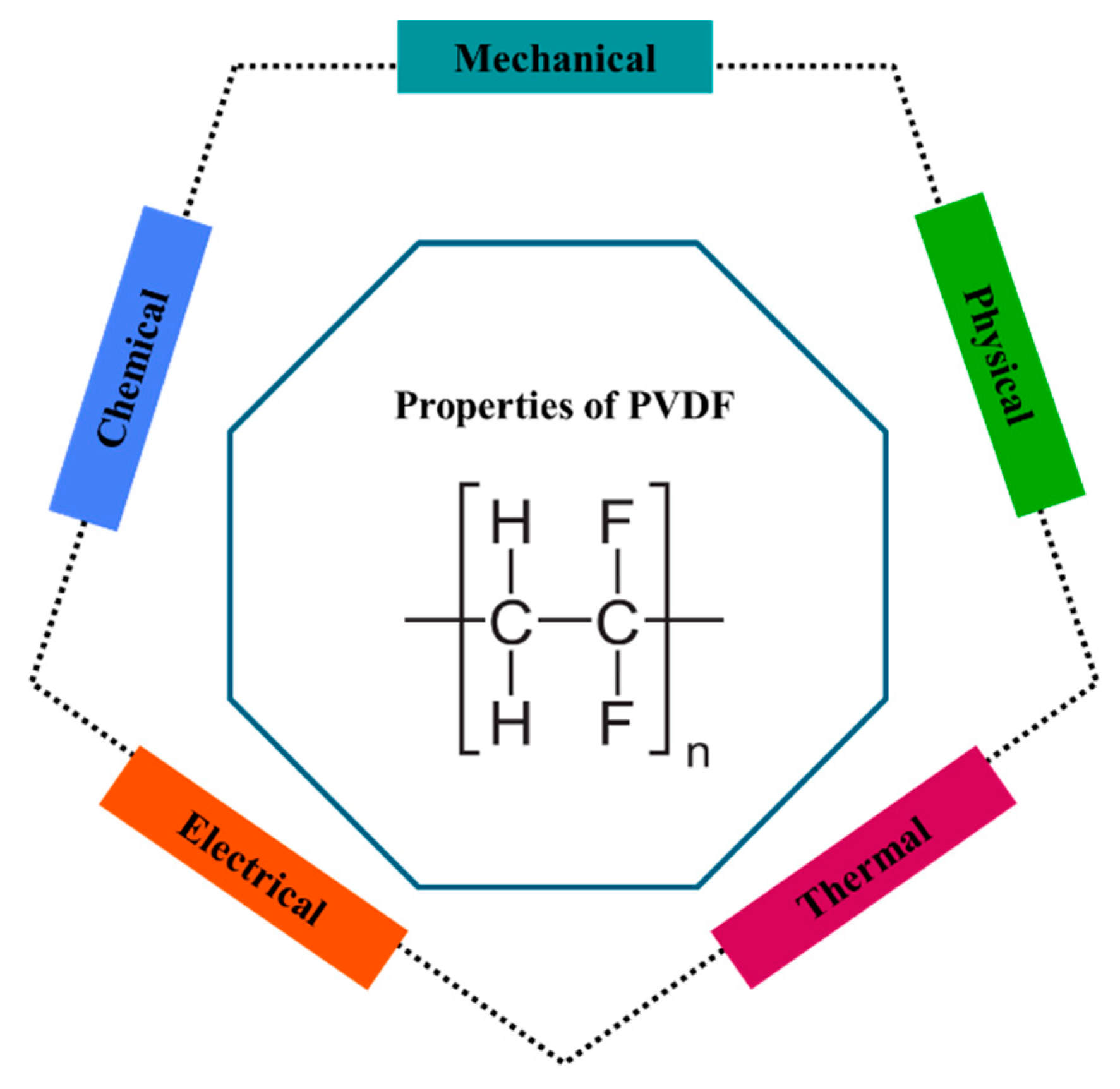
Figure 2.
Different phases of PVDF and their properties. (a) α-phase, (b) β-phase, and (c) γ-phase. Redrwed refer to reference [79].
Figure 2.
Different phases of PVDF and their properties. (a) α-phase, (b) β-phase, and (c) γ-phase. Redrwed refer to reference [79].
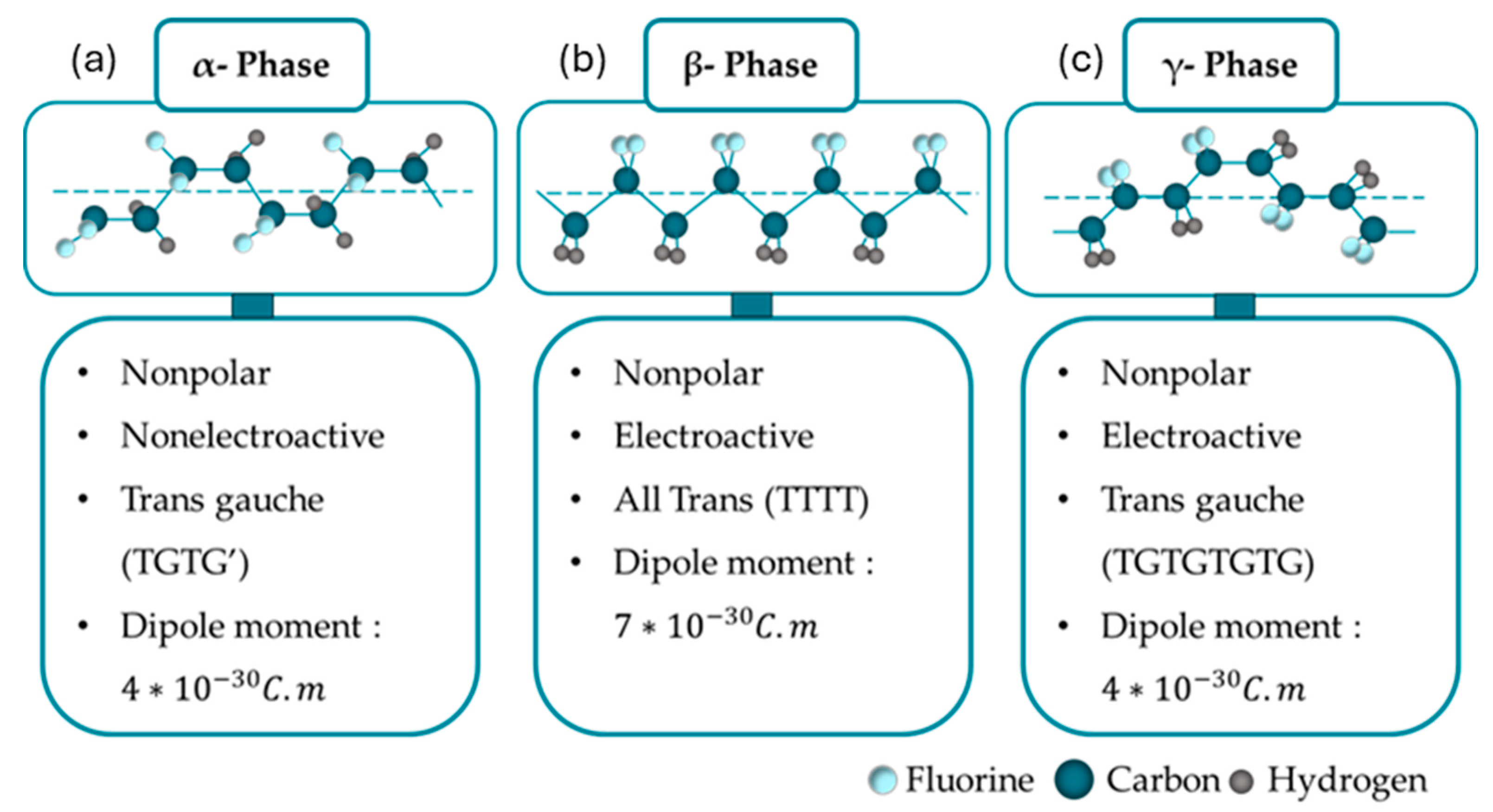
Figure 3.
A Heckman diagram. Redrwed, refer to reference [89].
Figure 3.
A Heckman diagram. Redrwed, refer to reference [89].
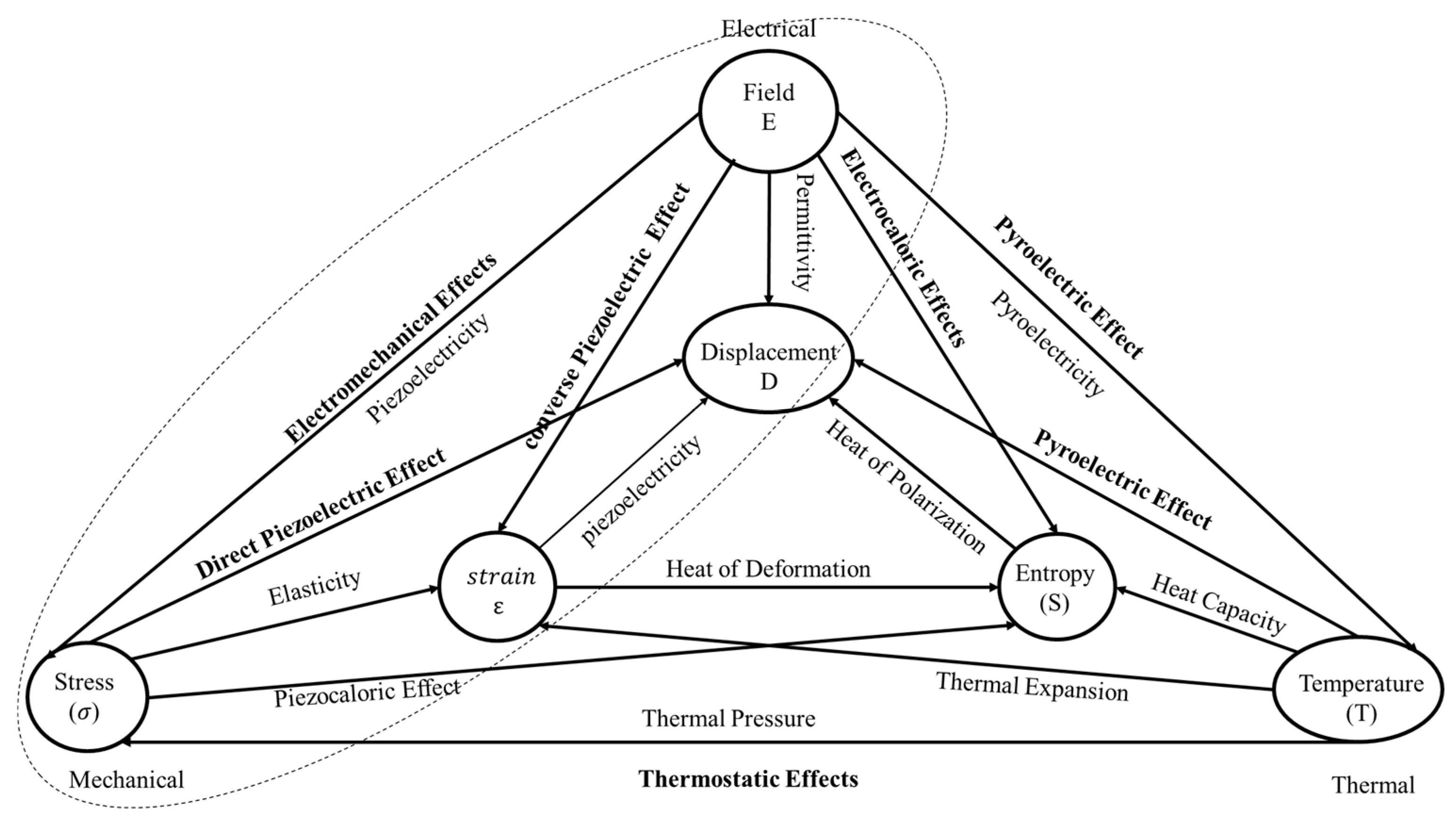
Figure 4.
Poling of a ferroelectric. (a) The material initially has a random arrangement of domains. (b) Application of an electric field at elevated temperature aligns domains with the field. (c) Once cooled to room temperature the field is removed and a remnant polarisation and strain is observed. The poled material is piezoelectric.
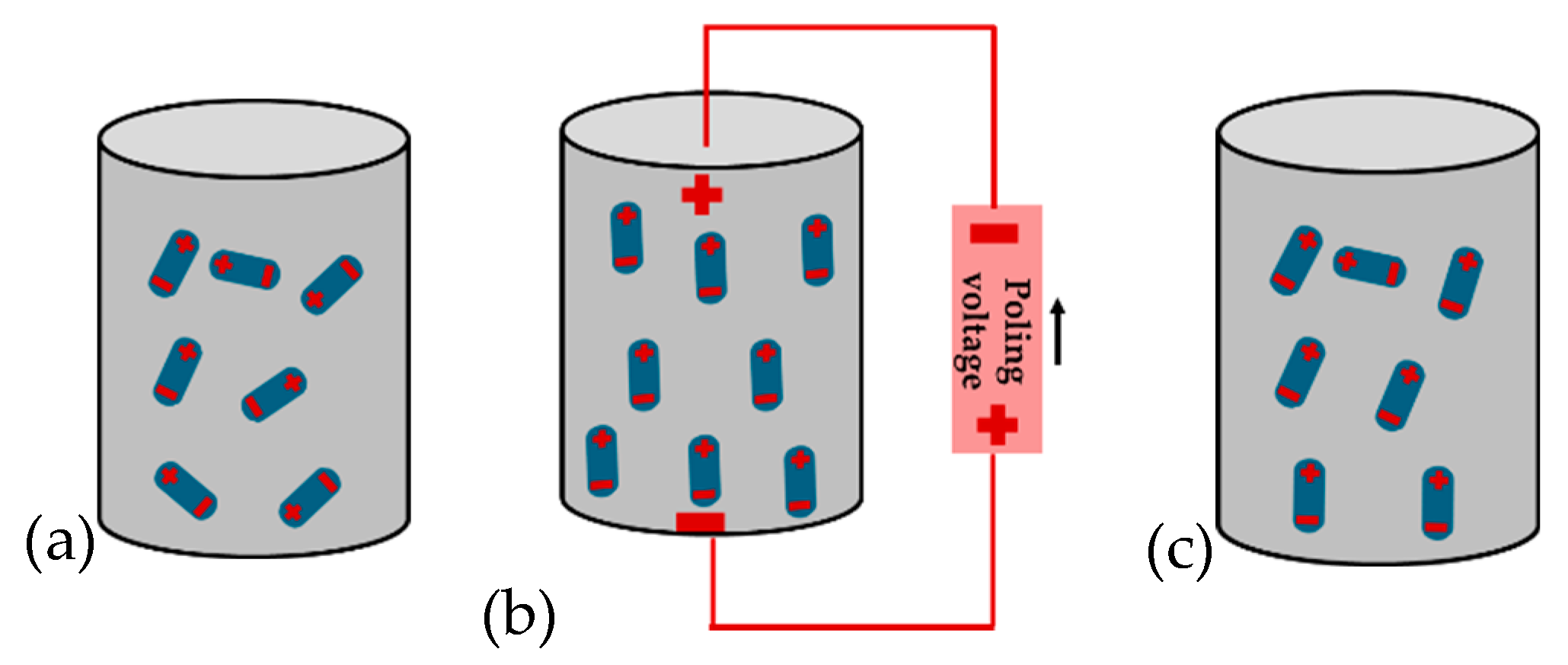
Figure 5.
Schematic representation of poling directions in PVDF material (a) direct piezoelectric effec (b) converse piezoelectric effect, (c) shear deformation [61] .
Figure 5.
Schematic representation of poling directions in PVDF material (a) direct piezoelectric effec (b) converse piezoelectric effect, (c) shear deformation [61] .
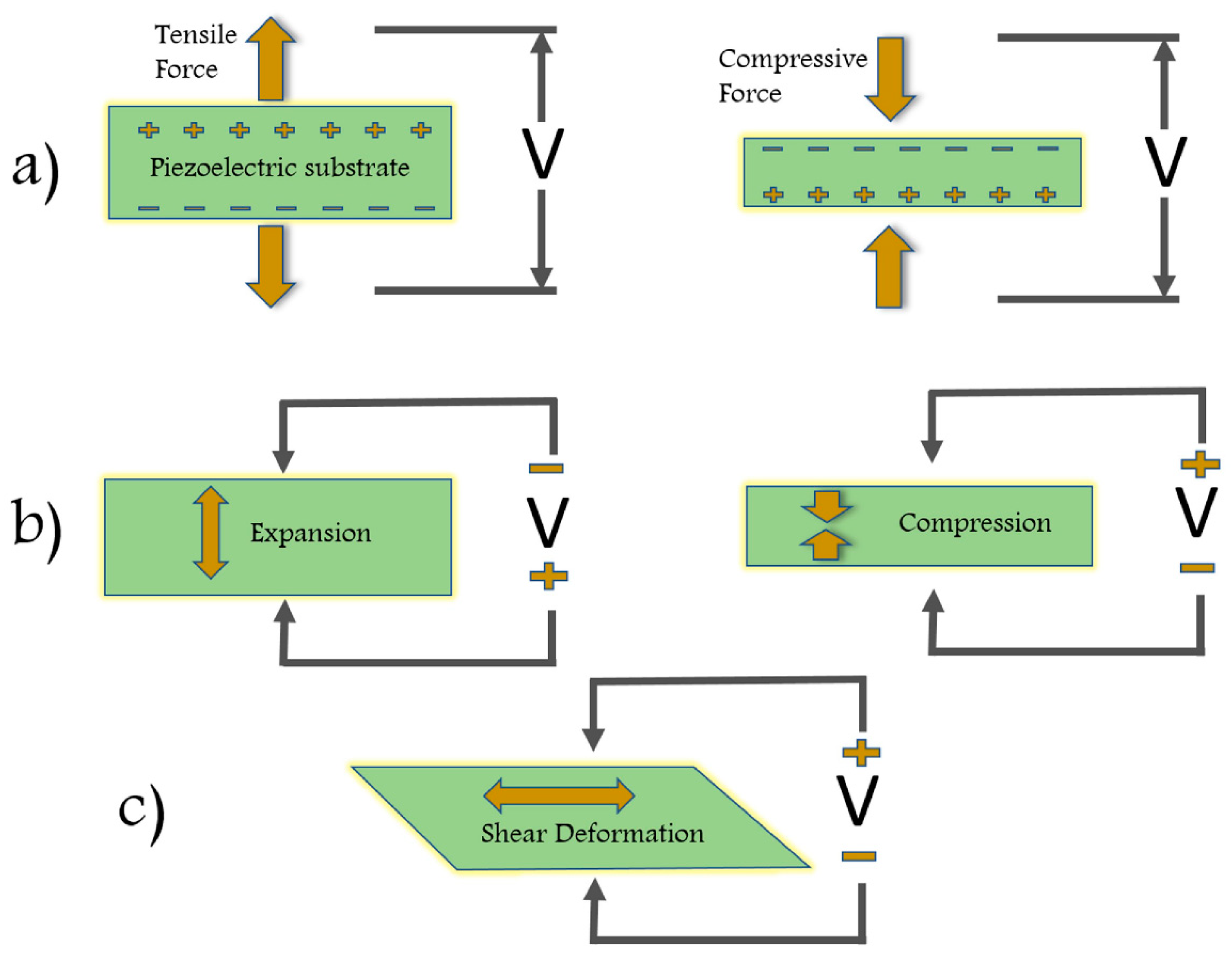
Figure 6.
The pyroelectric effect; (a) polarised material and corresponding surface charge (b) cooling leads to increase of polarisation leading to current reversal, (c) heating leads to a decrease in polarisation and free surface charge for current generation (d) applied thermal cycle.
Figure 6.
The pyroelectric effect; (a) polarised material and corresponding surface charge (b) cooling leads to increase of polarisation leading to current reversal, (c) heating leads to a decrease in polarisation and free surface charge for current generation (d) applied thermal cycle.
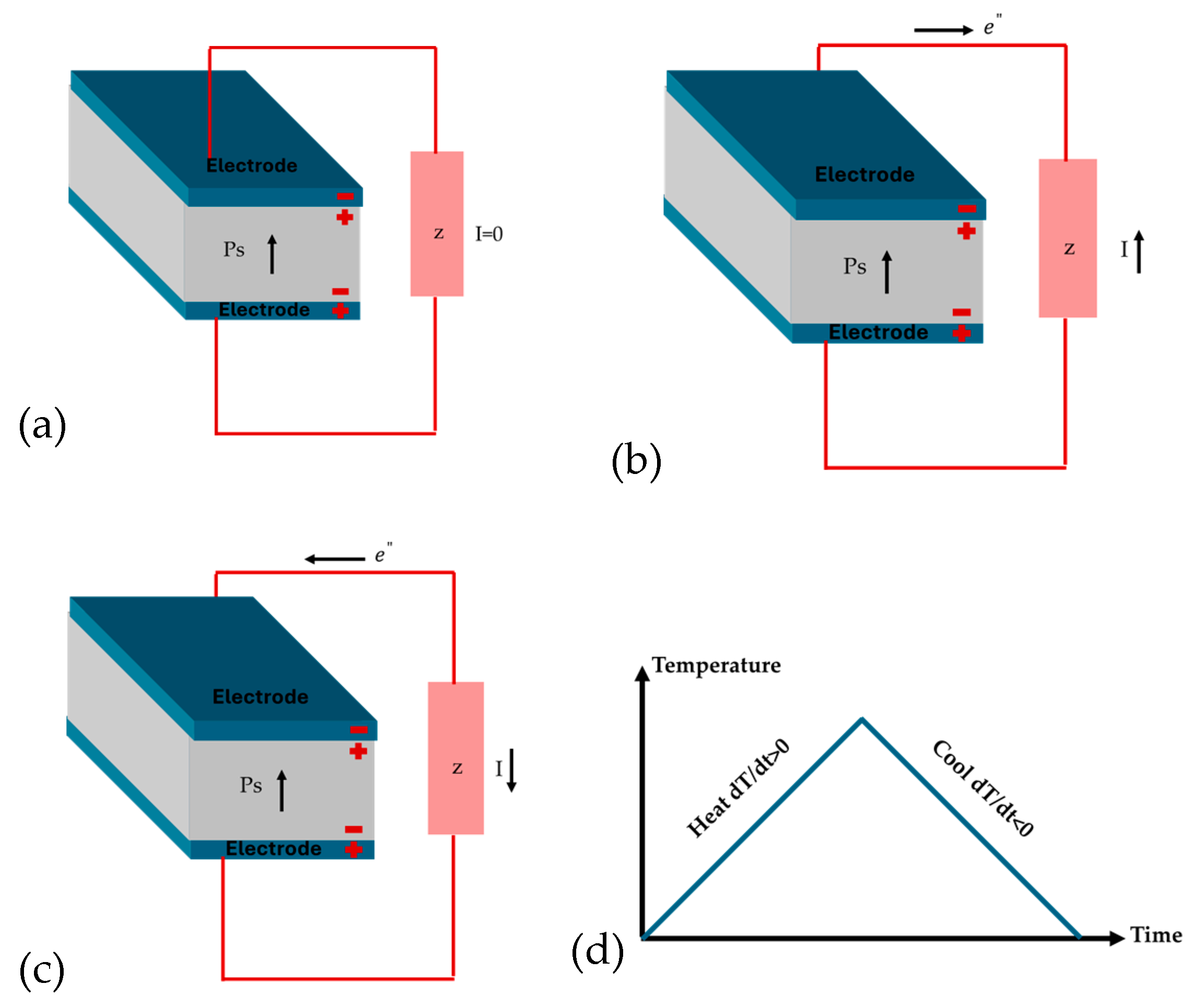
Figure 7.
Different methods of improving PVDF properties.
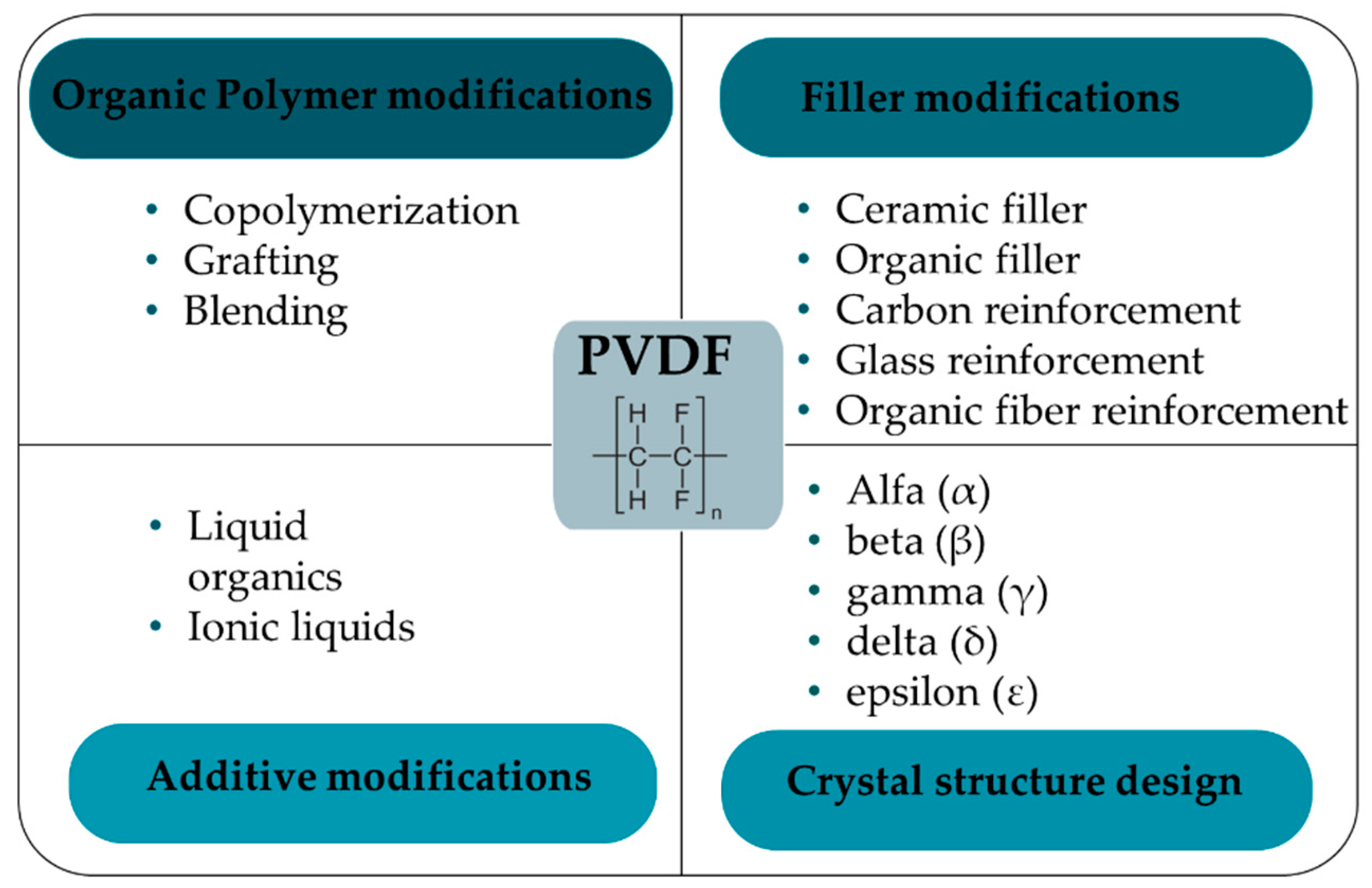
Figure 8.
Solution casting process for PVDF films.
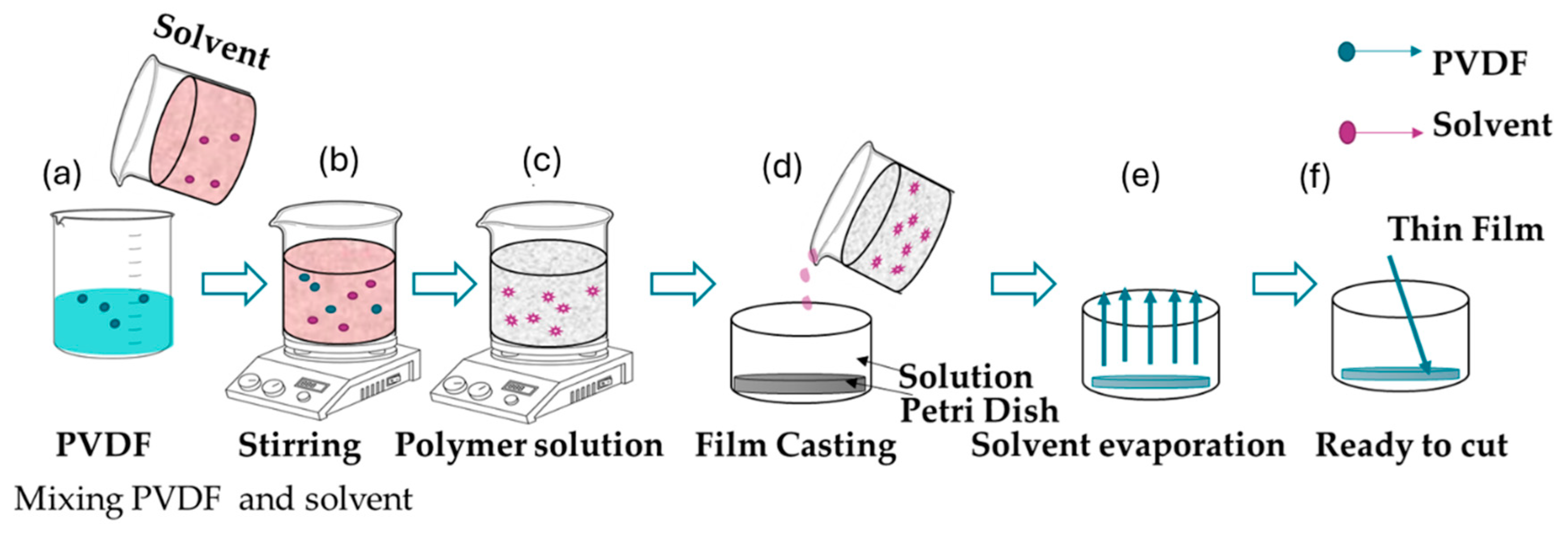
Figure 9.
Solution coating processing for PVDF films.
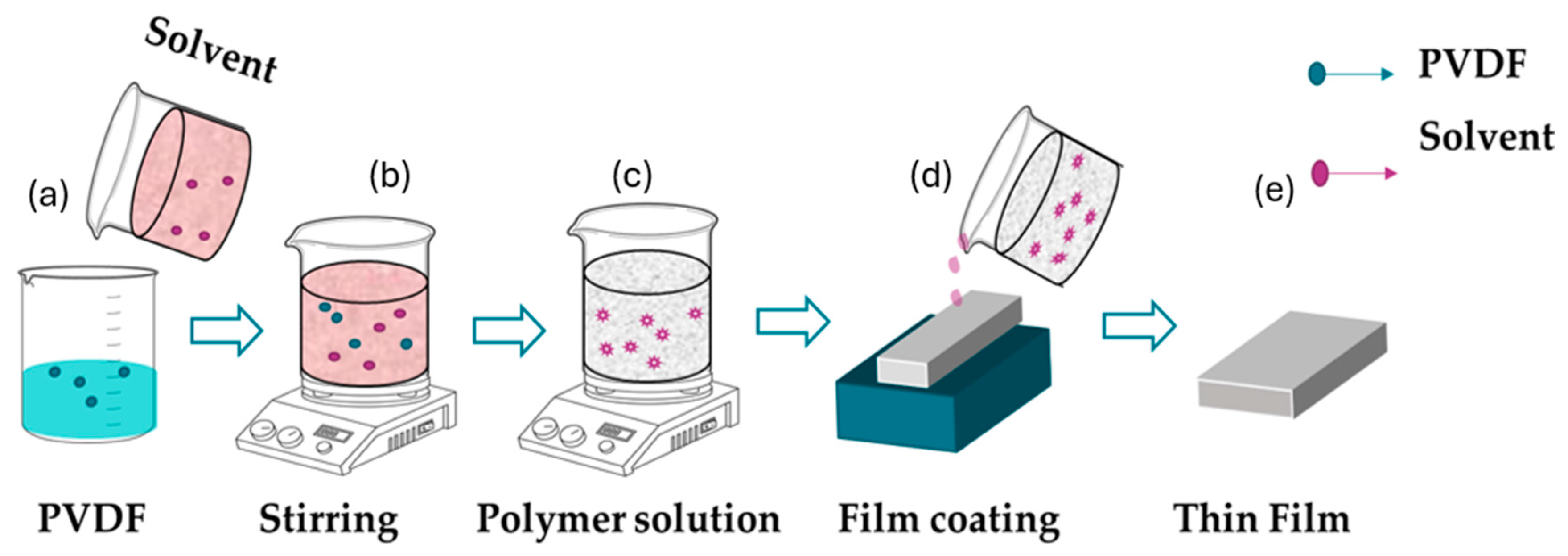
Figure 10.
Spin coating for PVDF films.
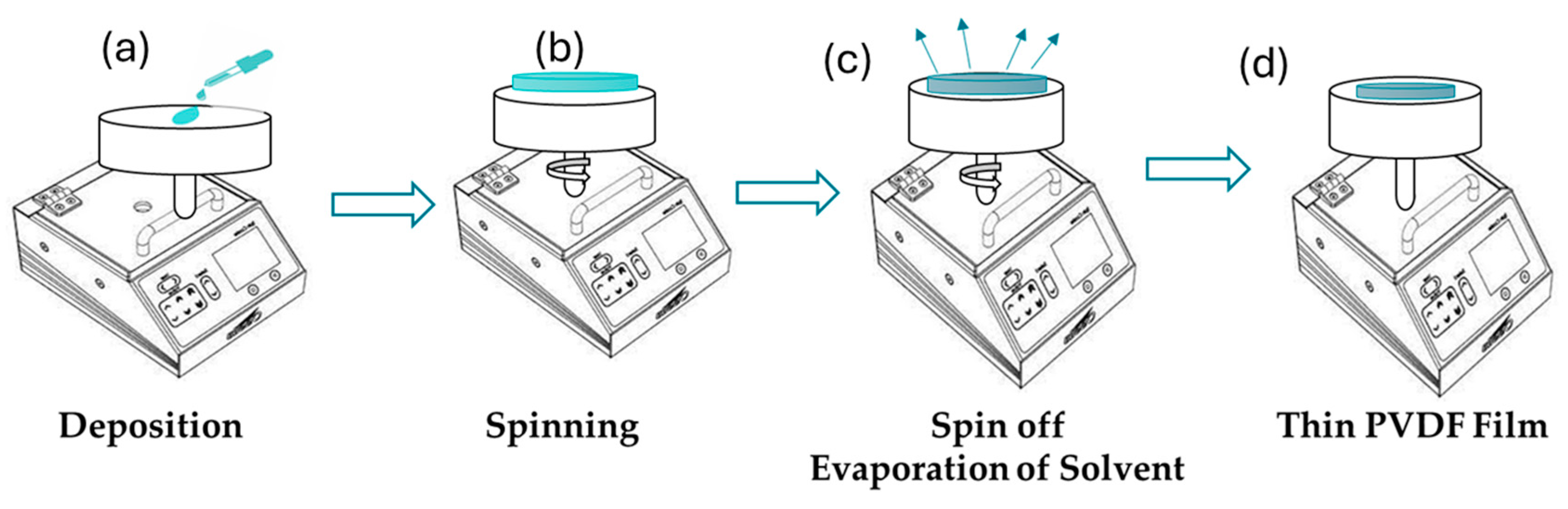
Figure 11.
(a) Hot pressing method for PVDF, (b) Equipment use for Hot pressing.
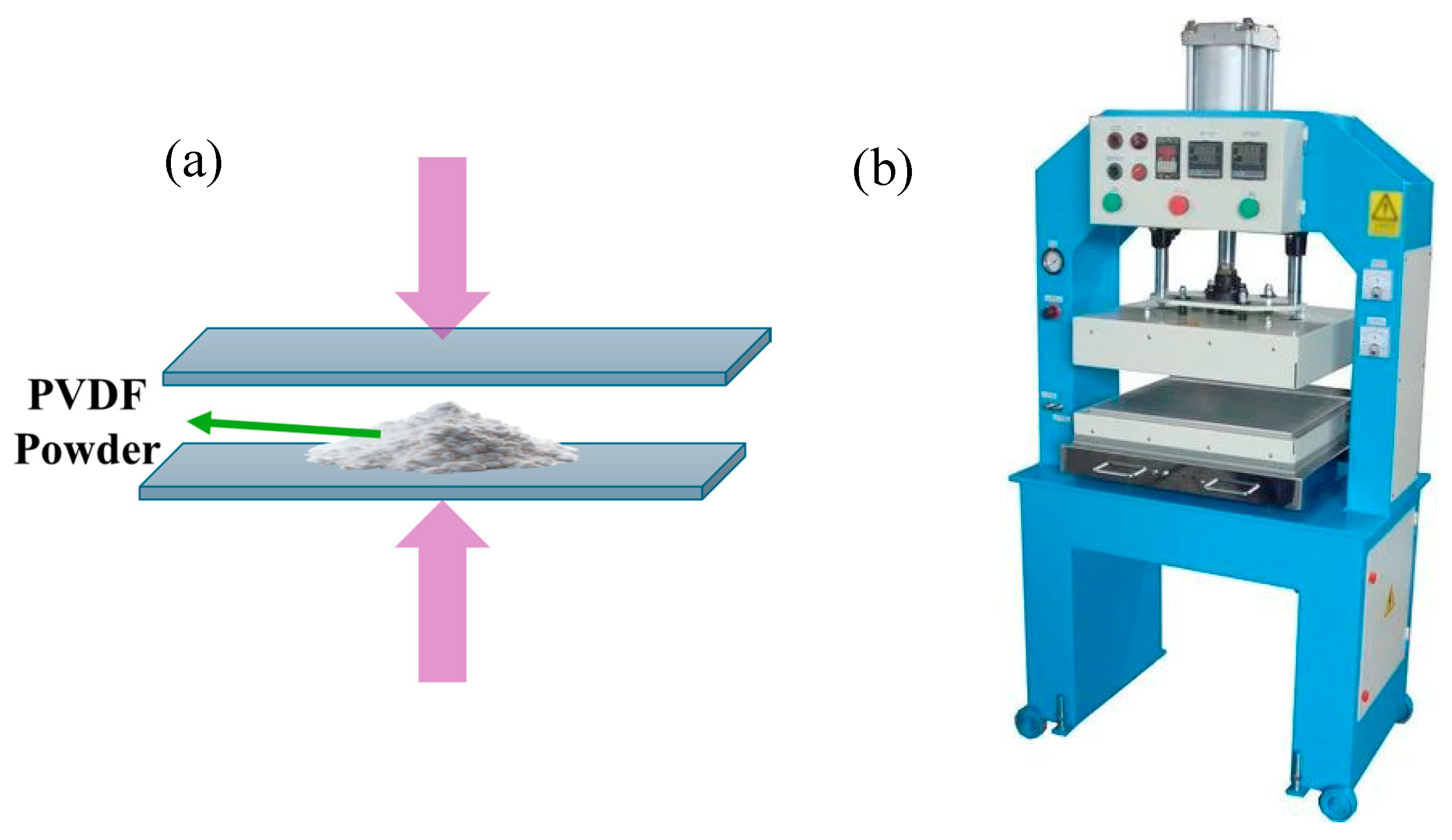
Figure 12.
Diagram of Electrospinning for PVDF films.
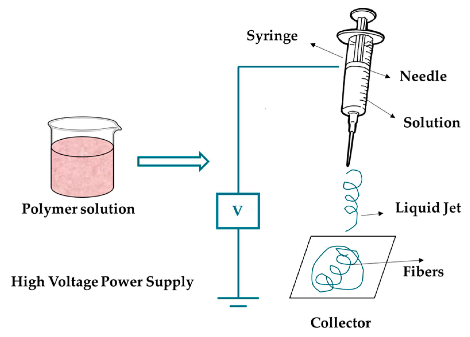
Figure 13.
A 3D printing mechanism for PVDF films.
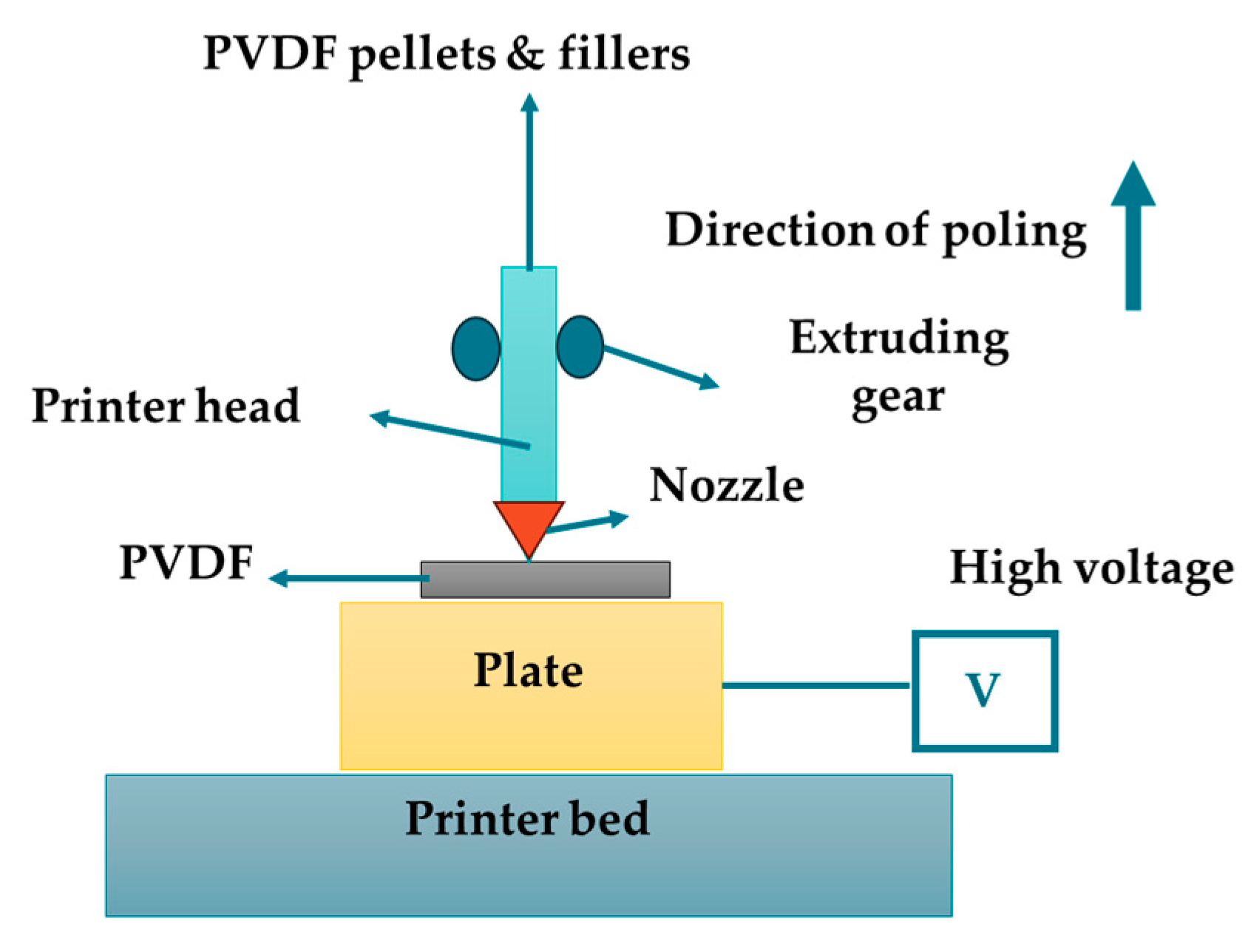
Figure 14.
The PVDF polymer's crystalline phase transformation diagram[148].
Figure 14.
The PVDF polymer's crystalline phase transformation diagram[148].
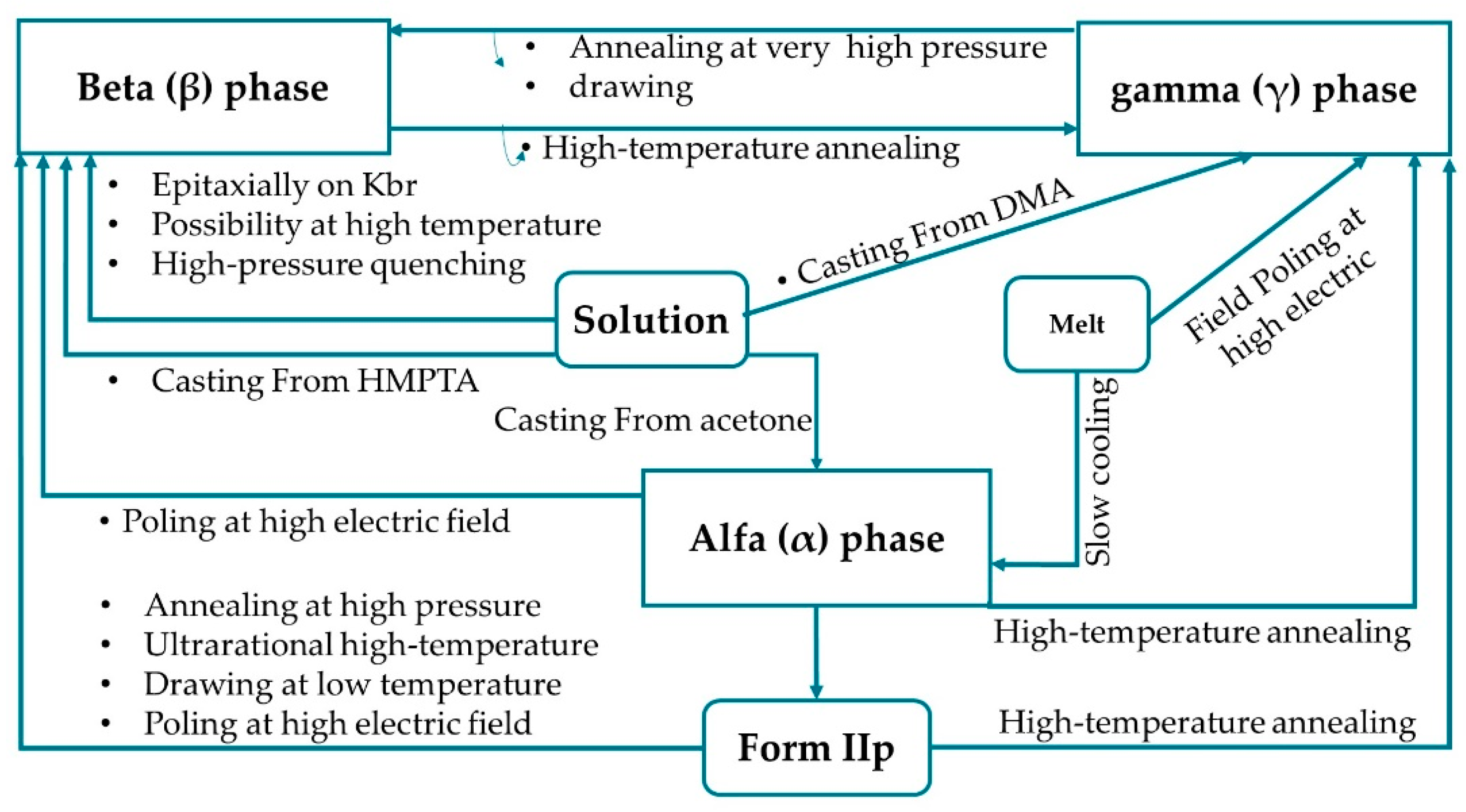
Figure 15.
Phase transition by temperature stretching method. 1D WAXS profiles during stretching at: (A) 60˚C, (B)140˚C [150].
Figure 15.
Phase transition by temperature stretching method. 1D WAXS profiles during stretching at: (A) 60˚C, (B)140˚C [150].
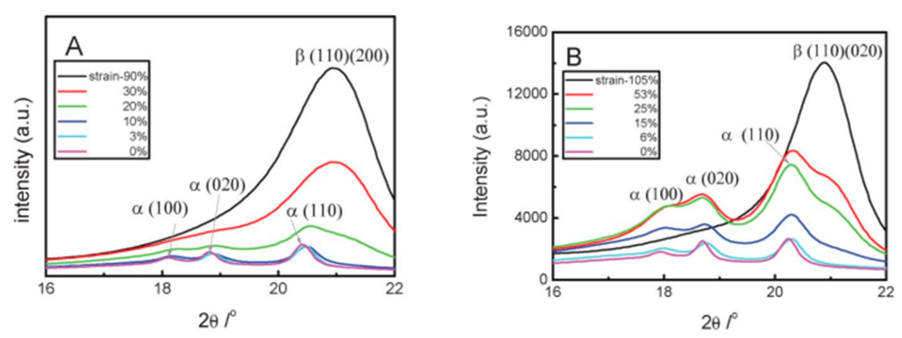
Figure 16.
Diagrammatic representation of PVDF films' uniaxial stretching process and structure formation phase change, crystalline orientation, and crystalline shape as the stretch ratio increases[153].
Figure 16.
Diagrammatic representation of PVDF films' uniaxial stretching process and structure formation phase change, crystalline orientation, and crystalline shape as the stretch ratio increases[153].
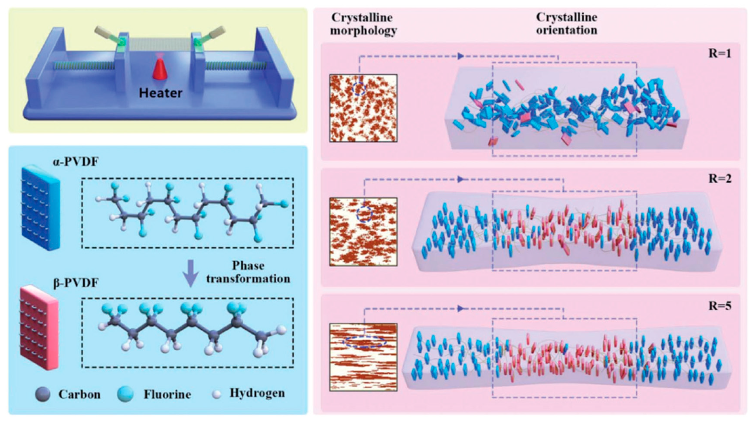
Figure 17.
Various stretching conditions of PVDF films for structure evolution. (a1) FTIR spectra, (a2) PVDF films' phase composition changes when the stretch ratio rises, (b1) DSC traces, (b2) Crystallinity and melting temperatures in relation to stretch ratios, (c1) 1D WAXD patterns, (c2) The (110)/(200)β phase's crystallite size and 2θ as a function of stretch ratio, determined by 1D XRD[153].
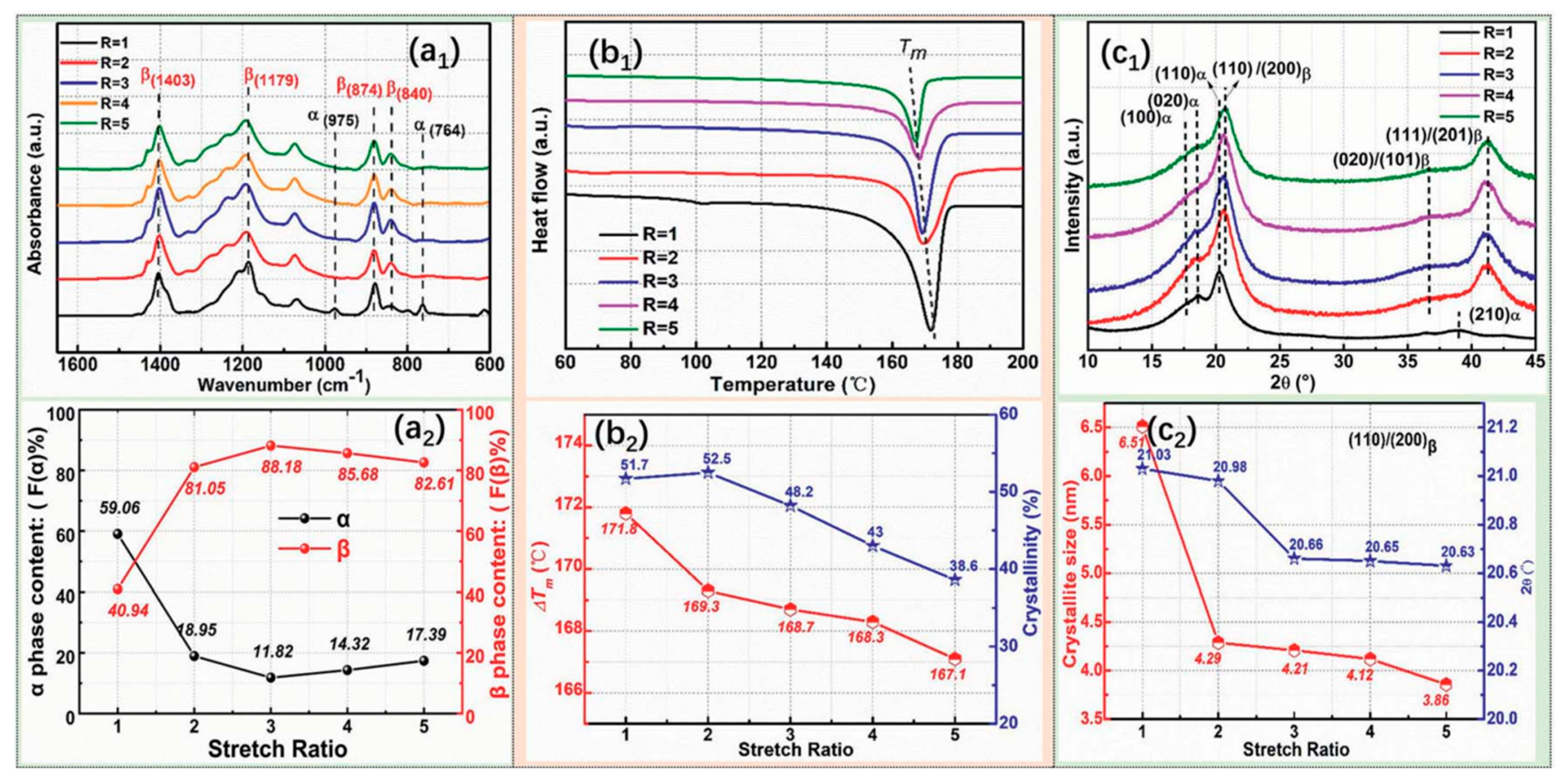
Figure 18.
Experiment setup biaxial stretching of PVDF [110].
Figure 18.
Experiment setup biaxial stretching of PVDF [110].
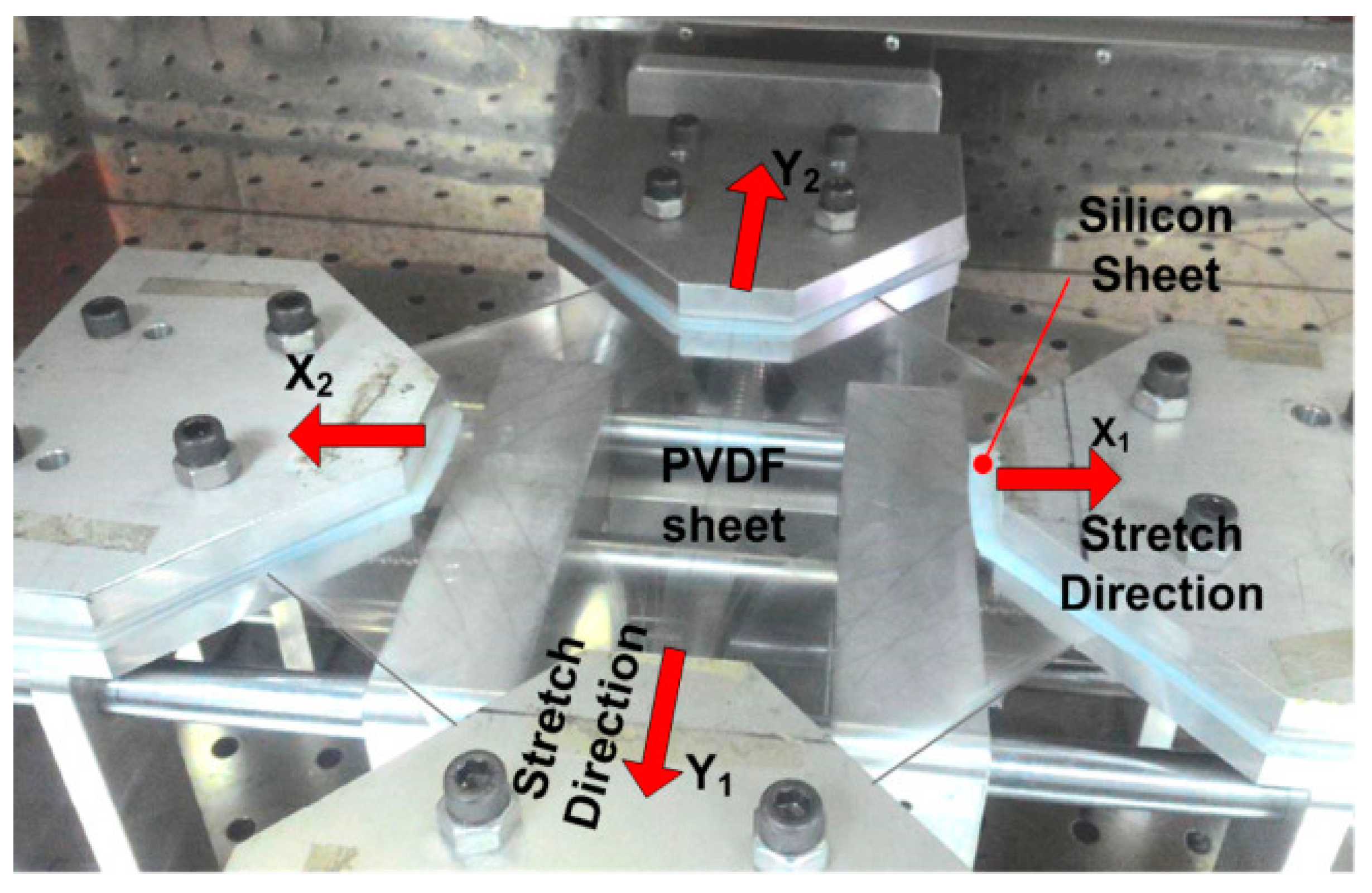
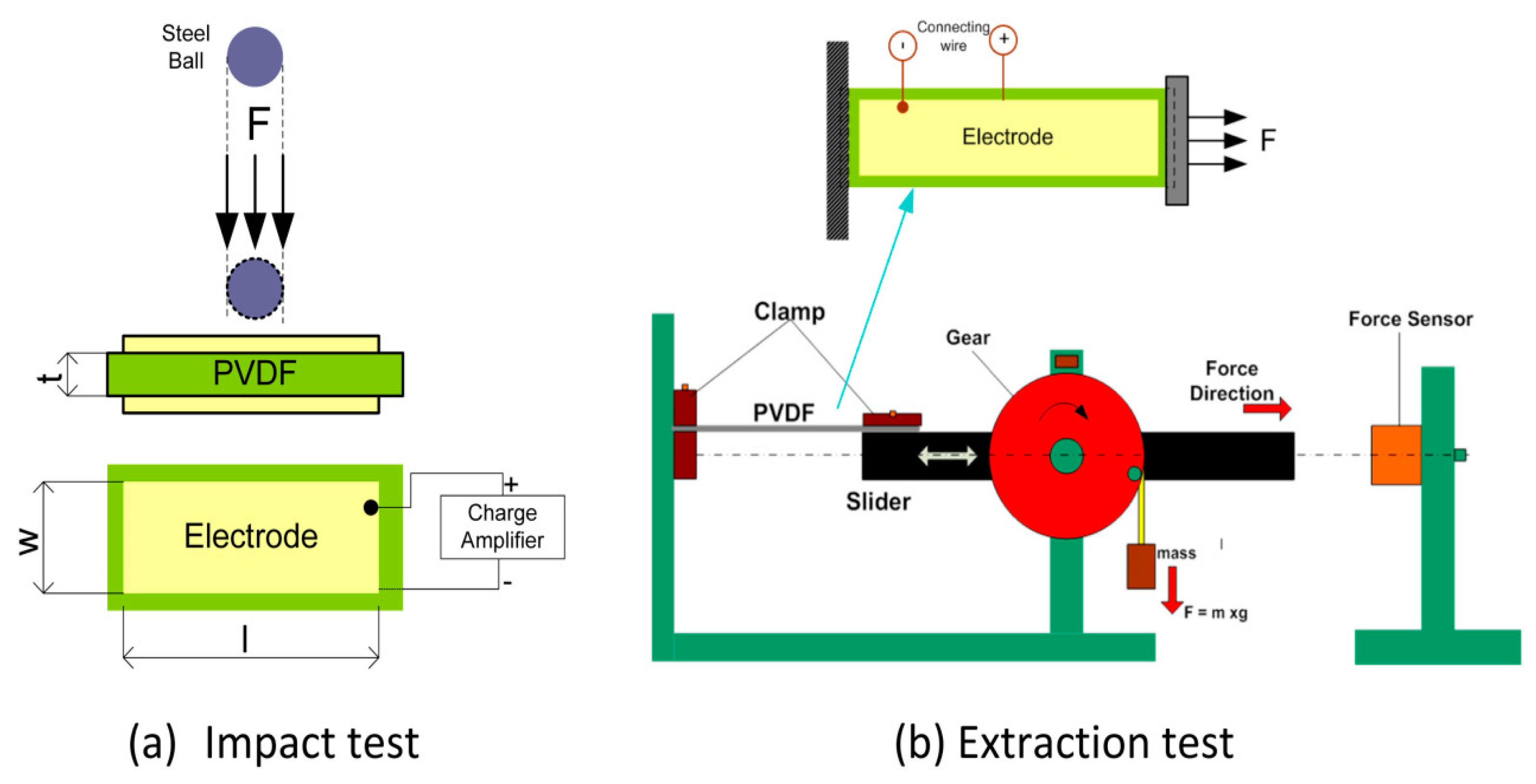
Figure 20.
FTIR spectra of stretched PVDF (a) uniaxial, (b–d) biaxial[110].
Figure 20.
FTIR spectra of stretched PVDF (a) uniaxial, (b–d) biaxial[110].
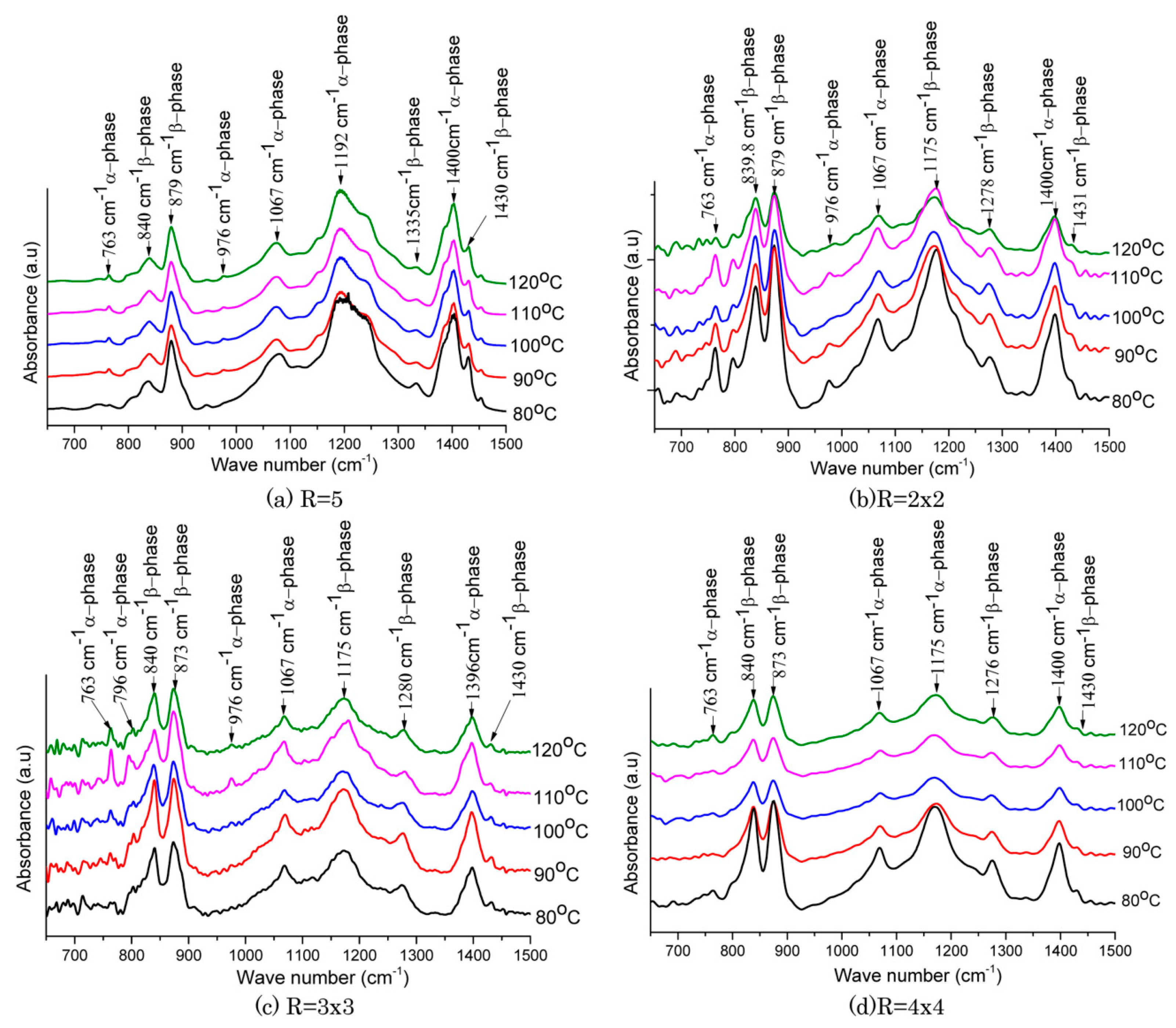
Figure 21.
Schematic diagram of in-situ polarization for PVDF film[165].
Figure 21.
Schematic diagram of in-situ polarization for PVDF film[165].
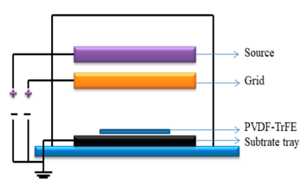
Figure 22.
Piezoelectric coefficient corresponding to different polarization voltage [165].
Figure 22.
Piezoelectric coefficient corresponding to different polarization voltage [165].
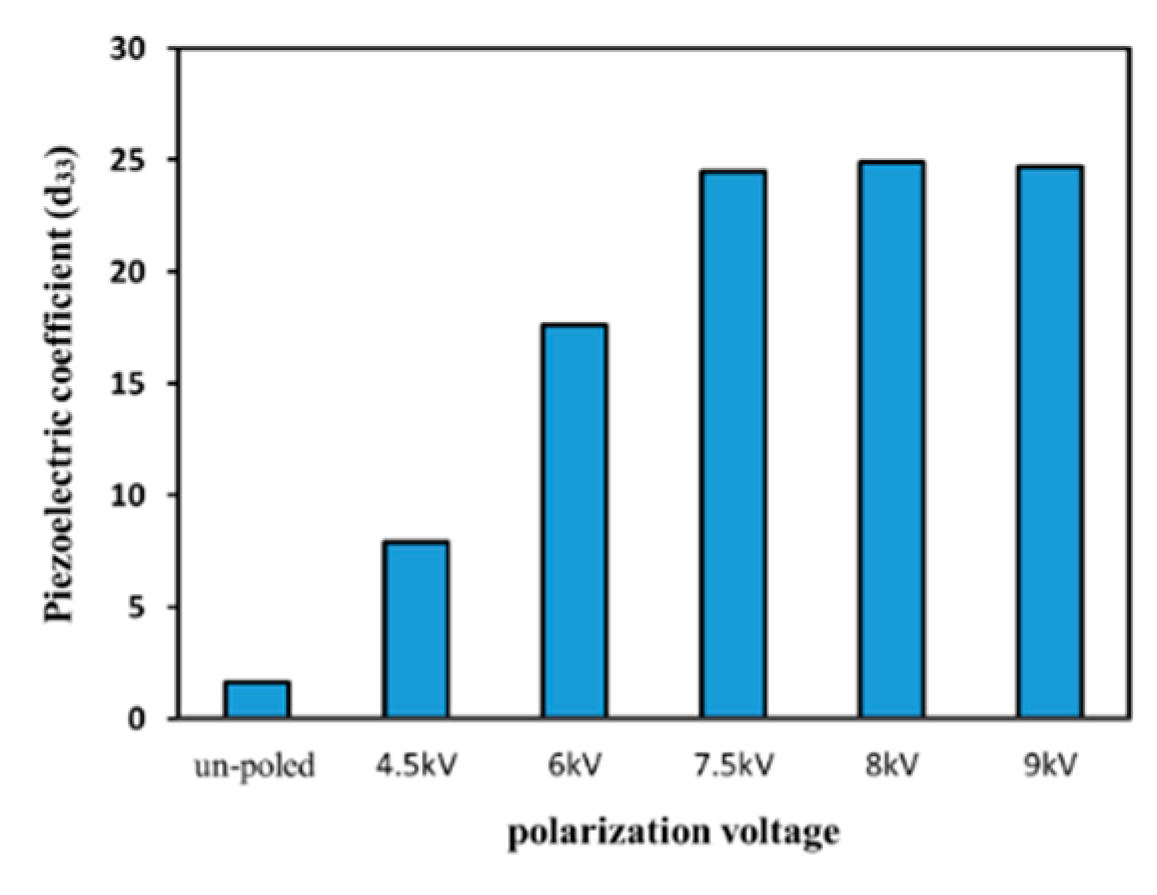
Figure 23.
XRD patterns of PVDF-TrFE films after poling [9].
Figure 23.
XRD patterns of PVDF-TrFE films after poling [9].
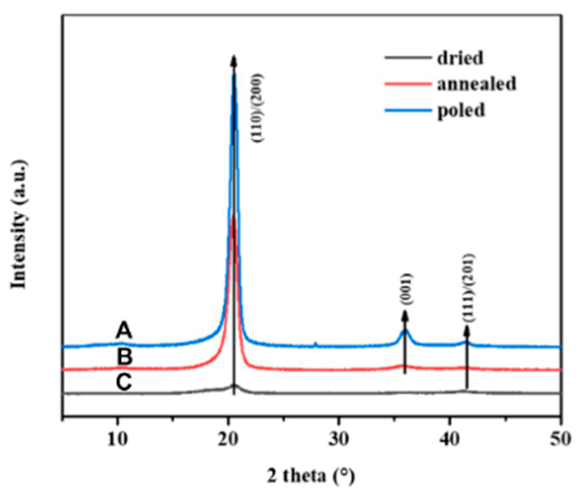
Figure 24.
schematic of setup for stretching and corona poling experiment [166].
Figure 24.
schematic of setup for stretching and corona poling experiment [166].
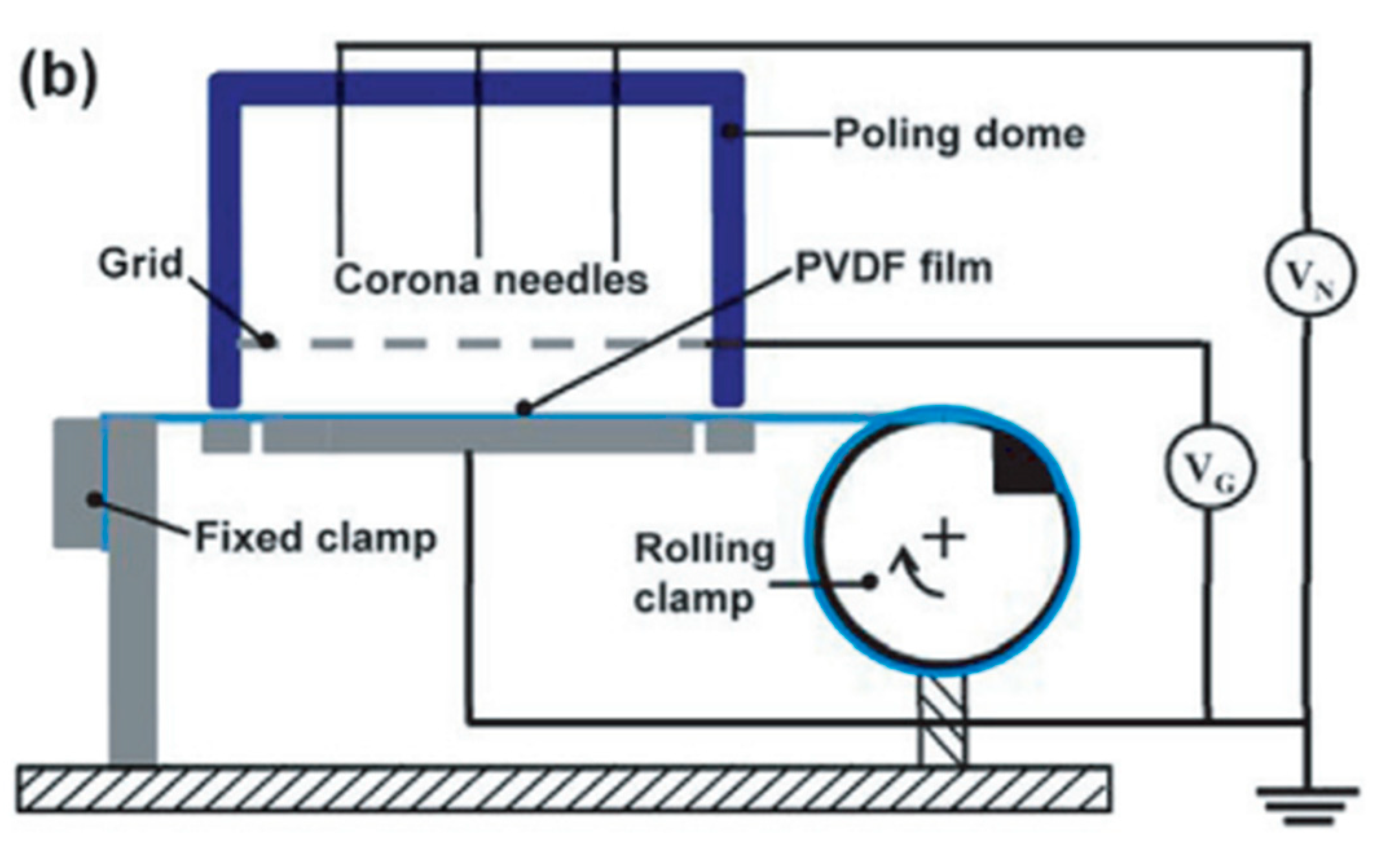
Figure 25.
(a) XRD patterns of PVDF after corona polarization, (b) FTIR spectra of PVDF [166].
Figure 25.
(a) XRD patterns of PVDF after corona polarization, (b) FTIR spectra of PVDF [166].
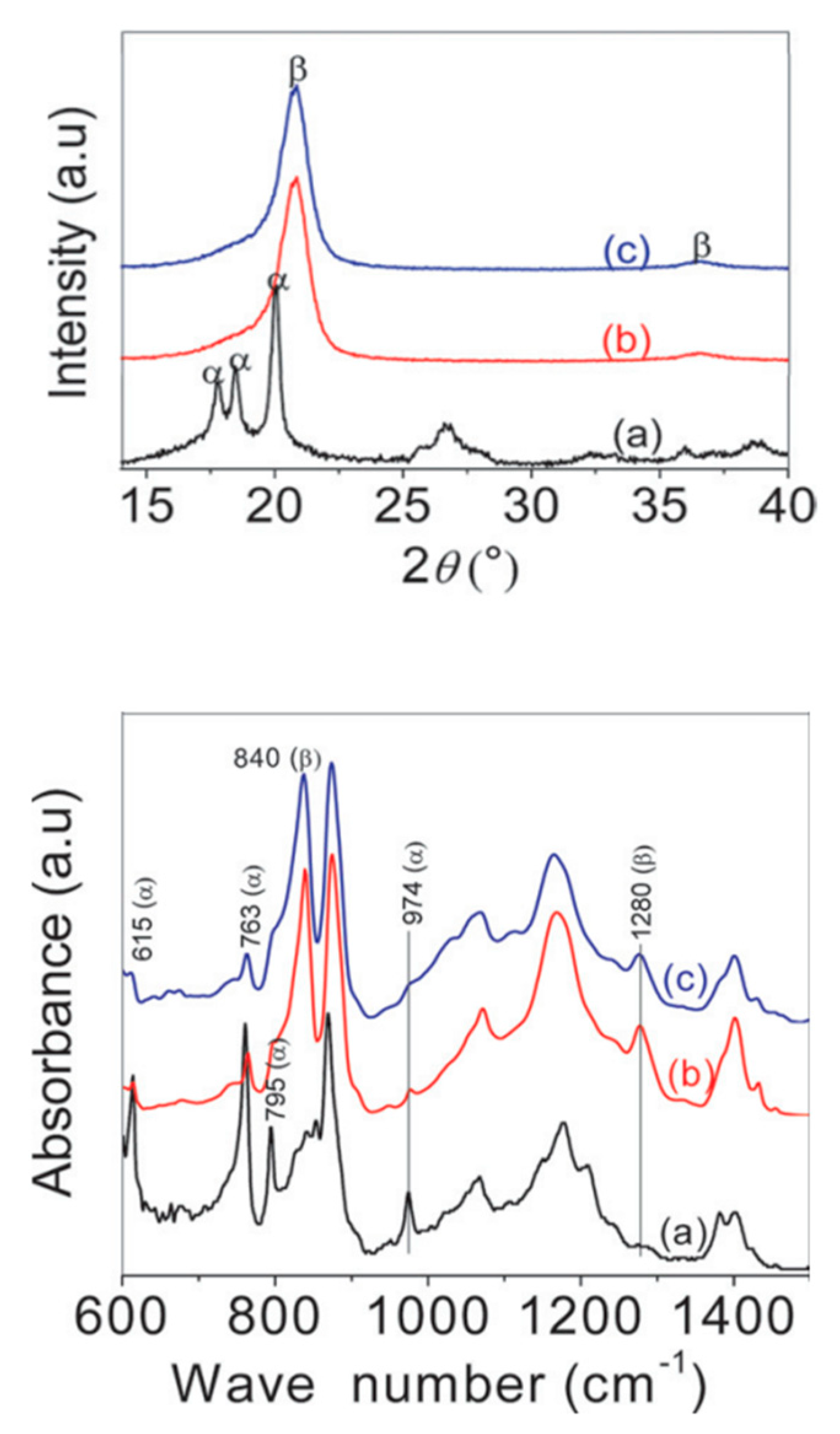
Figure 26.
PVDF Co-Polymers (a) poly (vinylidene fluoride-hexafluoropropylene), (b) poly(vinylidene fluoride-co-trifluoroethylene), (c) poly(vinylidene fluoride-co-chlorotrifluoroethylene).
Figure 26.
PVDF Co-Polymers (a) poly (vinylidene fluoride-hexafluoropropylene), (b) poly(vinylidene fluoride-co-trifluoroethylene), (c) poly(vinylidene fluoride-co-chlorotrifluoroethylene).
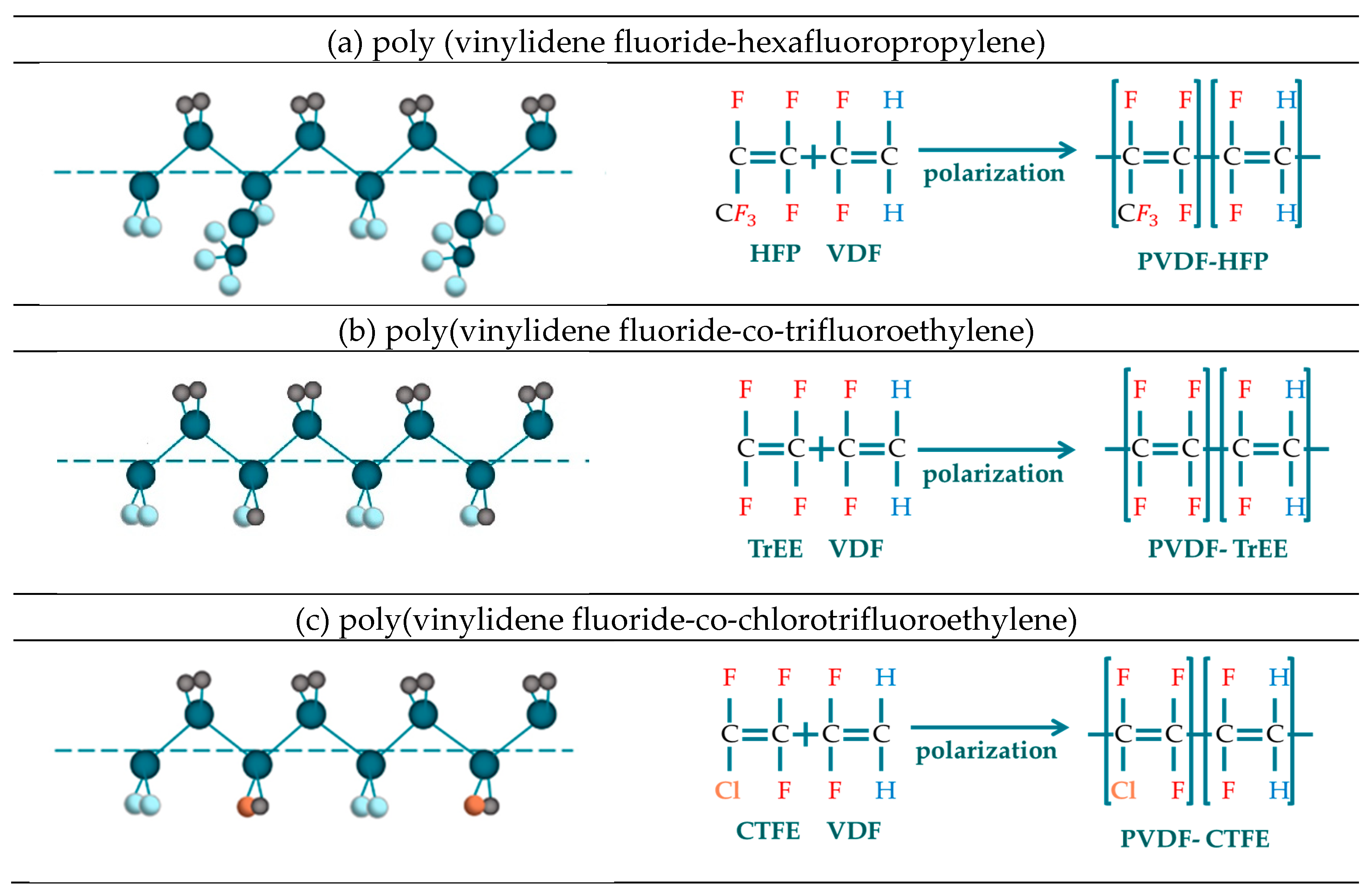
Figure 27.
Effect of various nanofillers on PVDF properties and their applications.
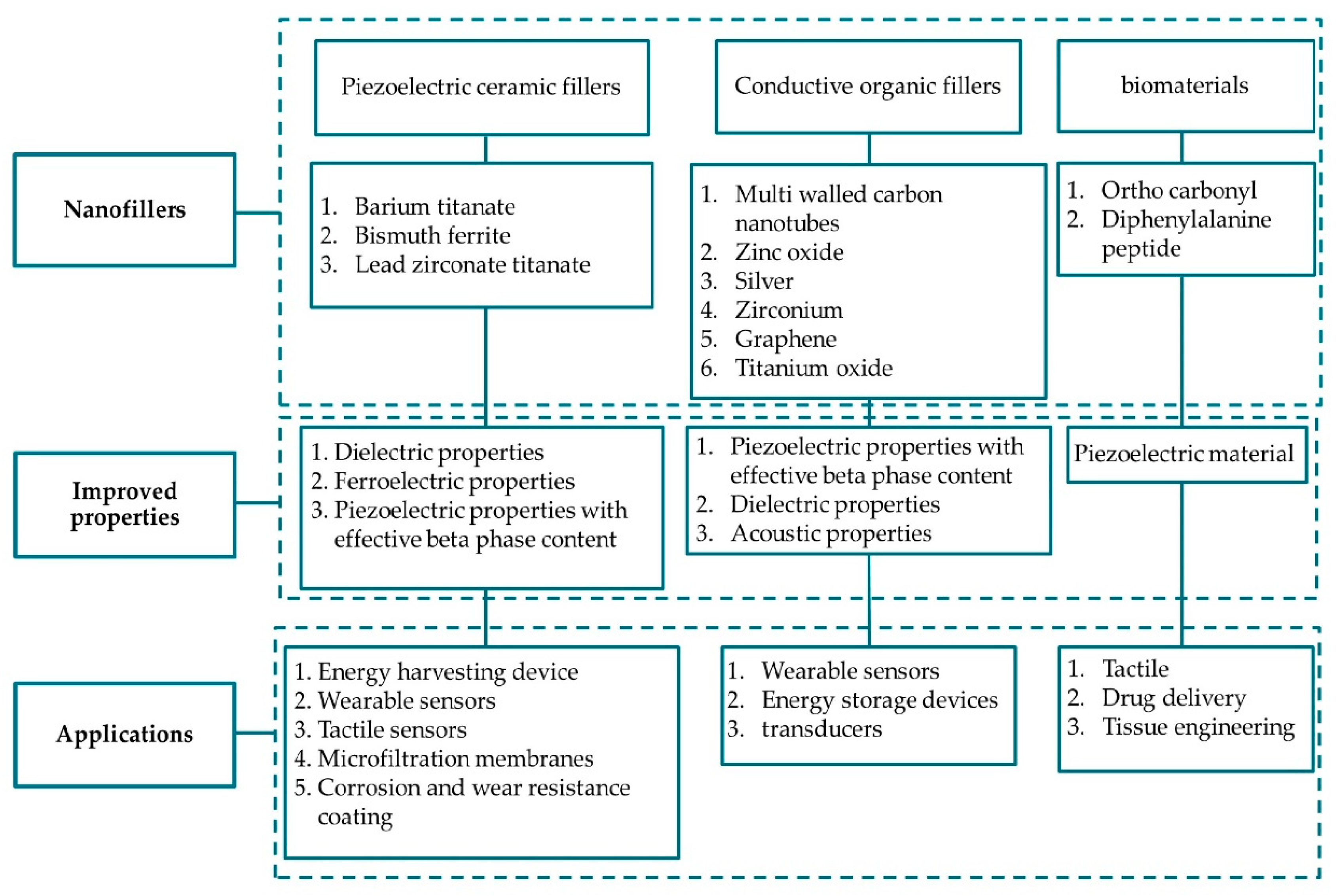
Figure 28.
The classification of thermoplastics blending criteria [198].
Figure 28.
The classification of thermoplastics blending criteria [198].
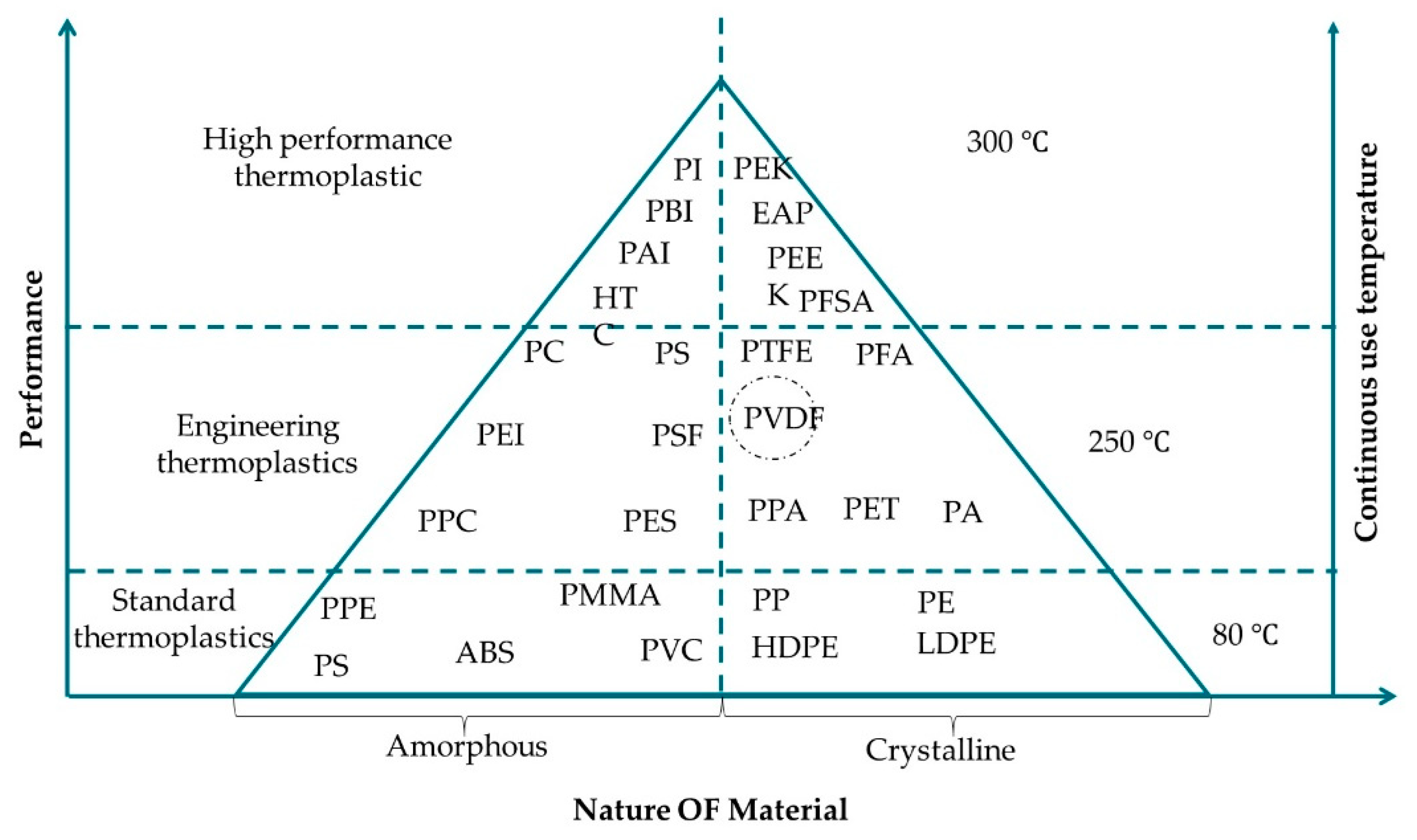
Figure 29.
Different methods used for PVDF characterization a) Crystalline and amorphous regions-DSC b) Crystallin phases – FTIR,XRD,Raman c) Net polarization P-E hysteresis [213].
Figure 29.
Different methods used for PVDF characterization a) Crystalline and amorphous regions-DSC b) Crystallin phases – FTIR,XRD,Raman c) Net polarization P-E hysteresis [213].
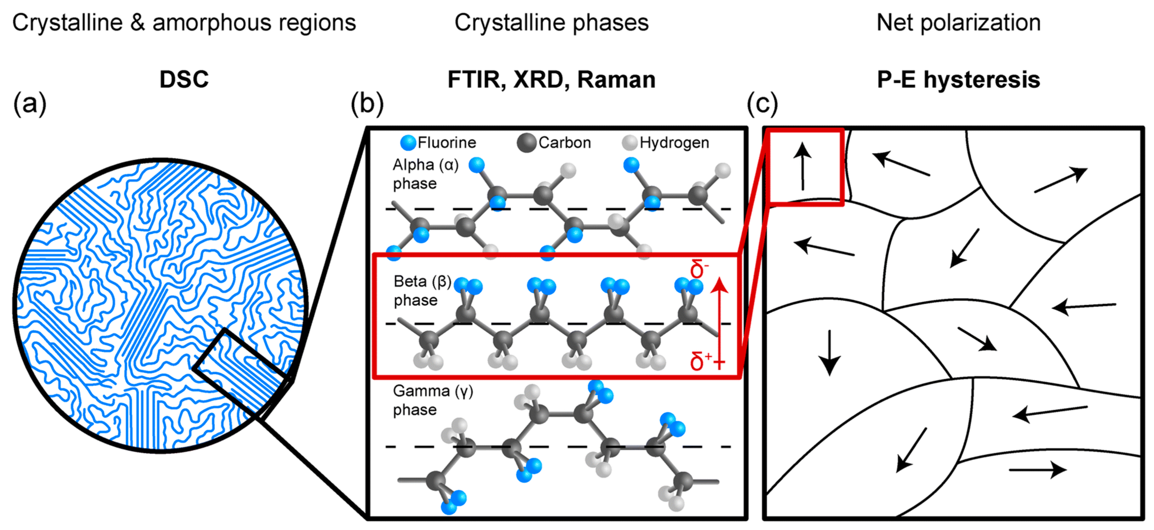
Figure 30.
Thermal analysis apparatus Differential Scanning Calorimeters, Discovery DSC 250 (www.tainstruments.com).
Figure 30.
Thermal analysis apparatus Differential Scanning Calorimeters, Discovery DSC 250 (www.tainstruments.com).
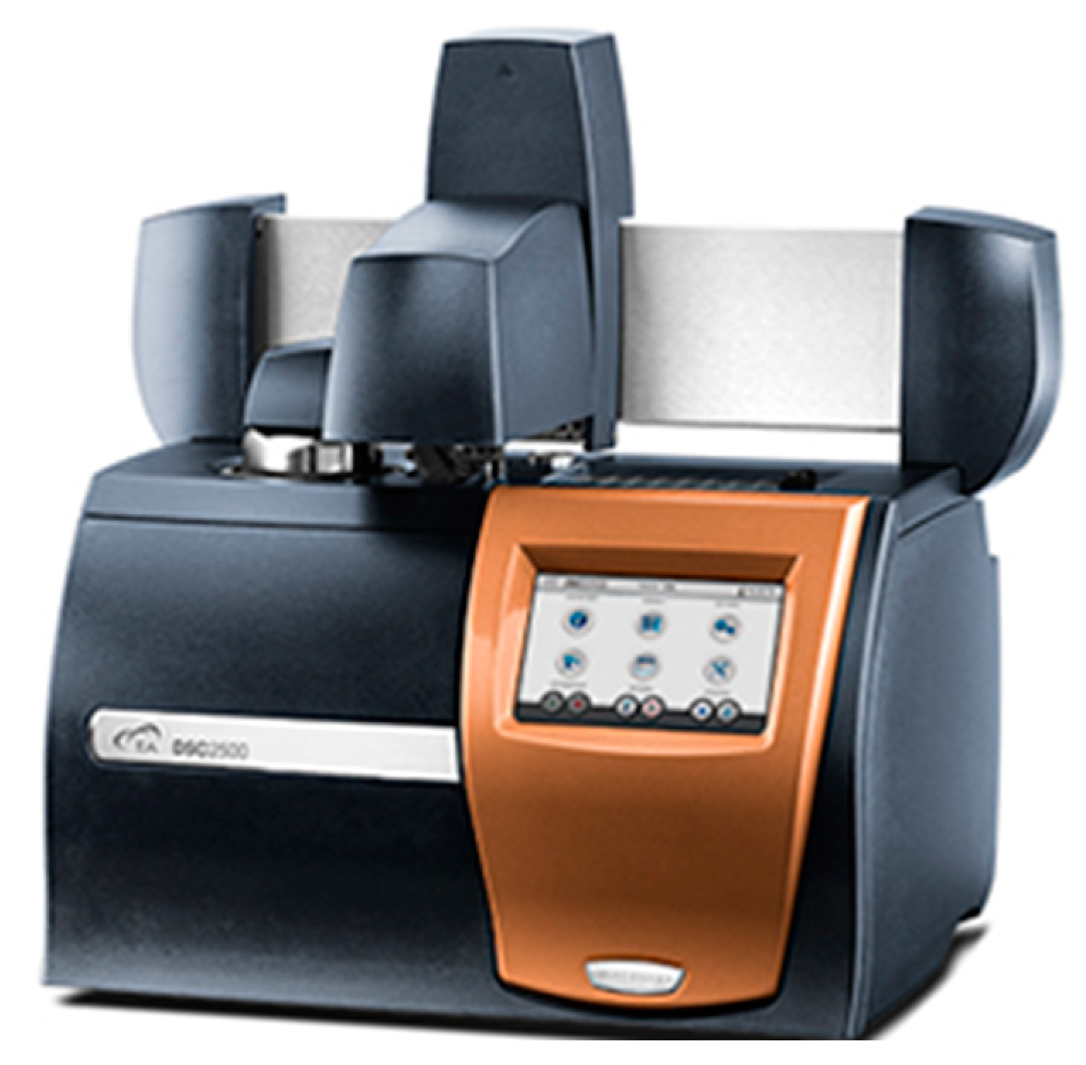
Figure 31.
Thermogravimetric instrument for high temperature and high-pressure thermogravimetric analysis. Discovery HP TGA – High Pressure TGA (www.tainstruments.com).
Figure 31.
Thermogravimetric instrument for high temperature and high-pressure thermogravimetric analysis. Discovery HP TGA – High Pressure TGA (www.tainstruments.com).
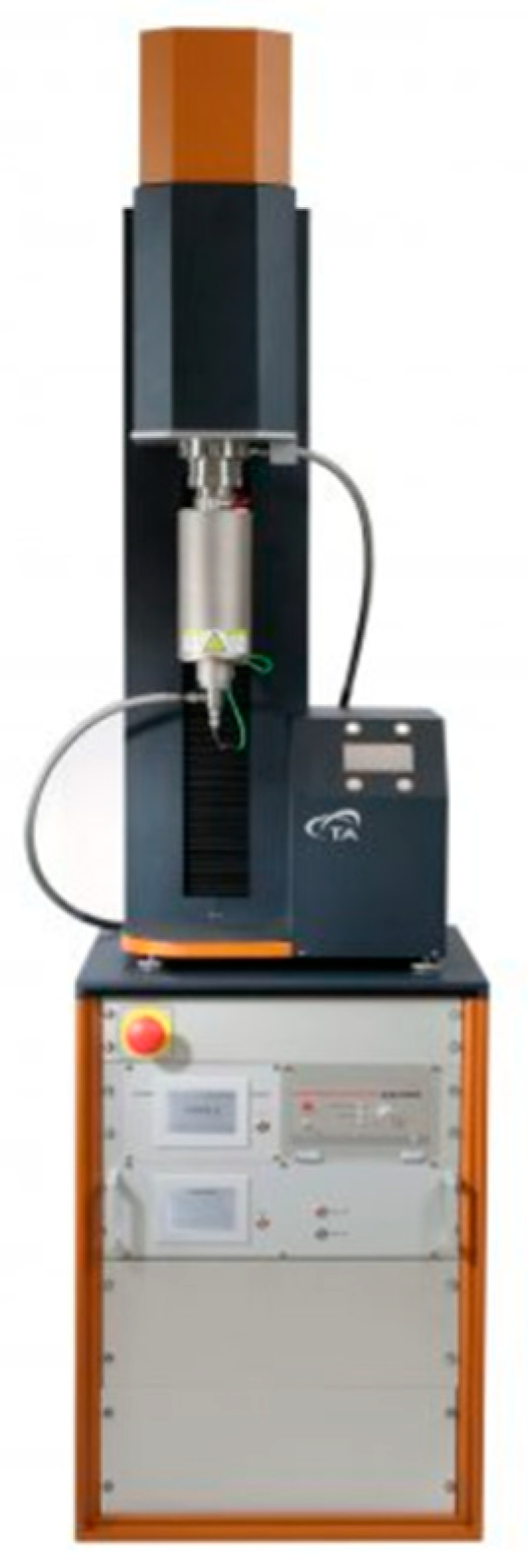
Figure 32.
PVDF's engineering stress-strain curves at various temperatures under uniaxial tensile deformation [150].
Figure 32.
PVDF's engineering stress-strain curves at various temperatures under uniaxial tensile deformation [150].
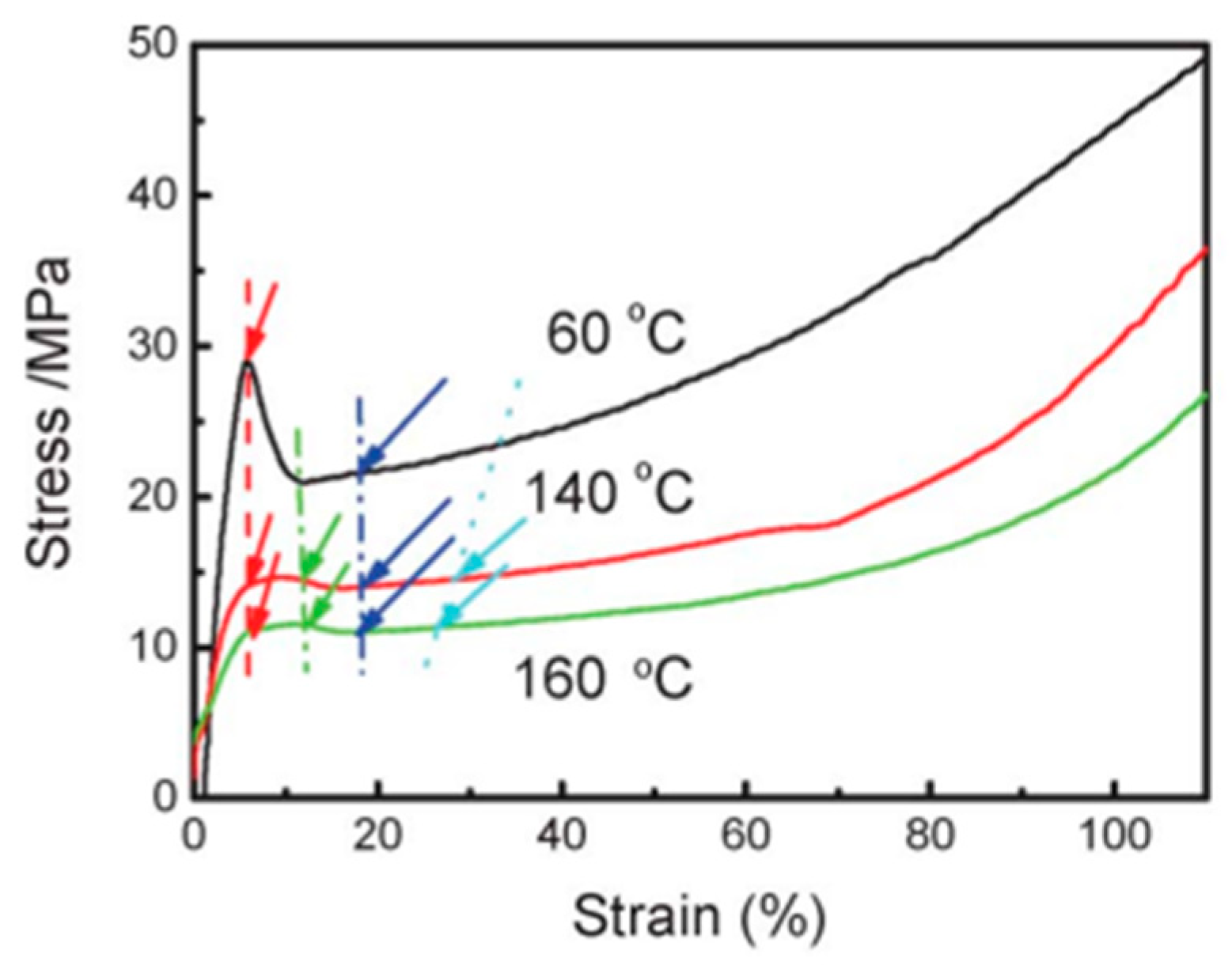
Figure 33.
Yield stress and yield strain at verious temperatures[150].
Figure 33.
Yield stress and yield strain at verious temperatures[150].
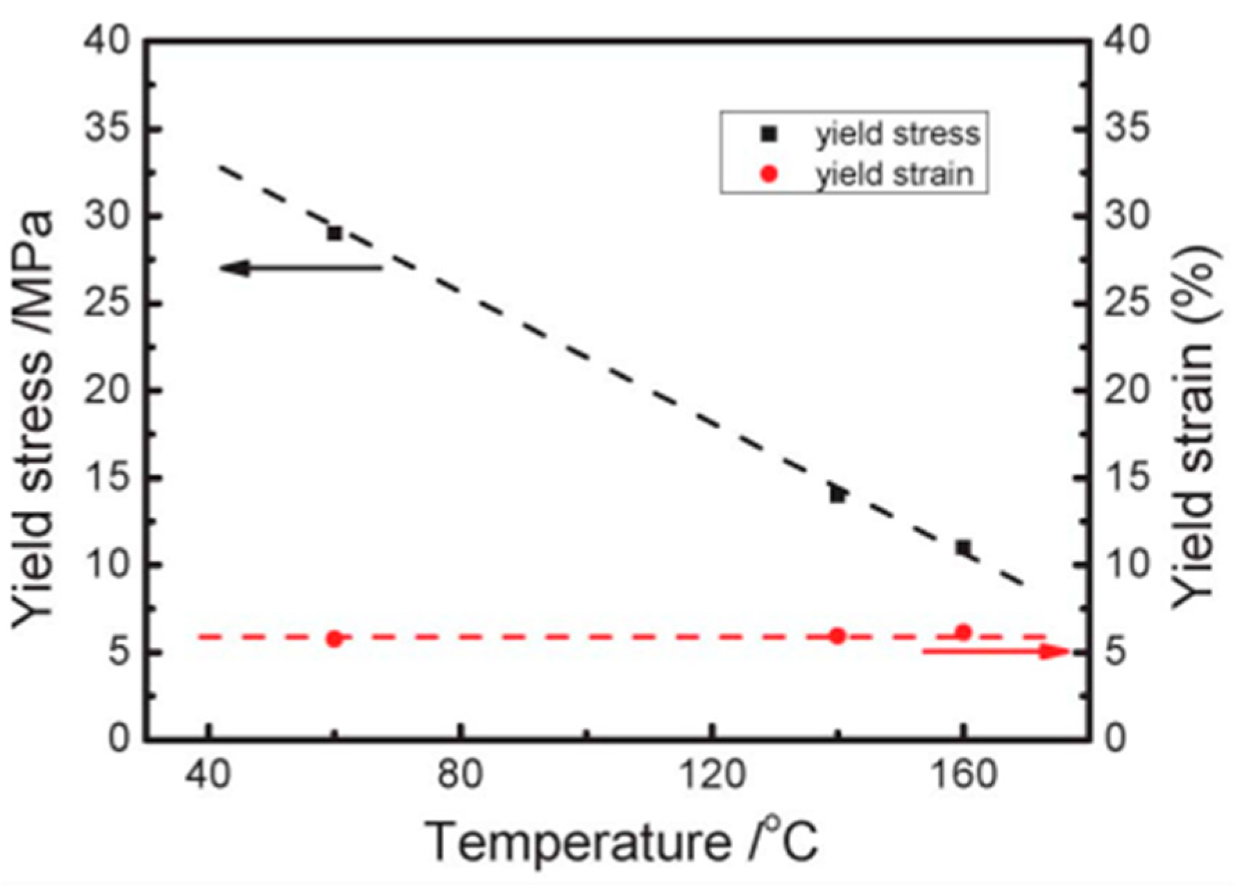
Figure 34.
FTIR Spectrometers: a) Nicolet™ iS50 FTIR Spectrometer https://www.thermofisher.com/ ,.
Figure 34.
FTIR Spectrometers: a) Nicolet™ iS50 FTIR Spectrometer https://www.thermofisher.com/ ,.
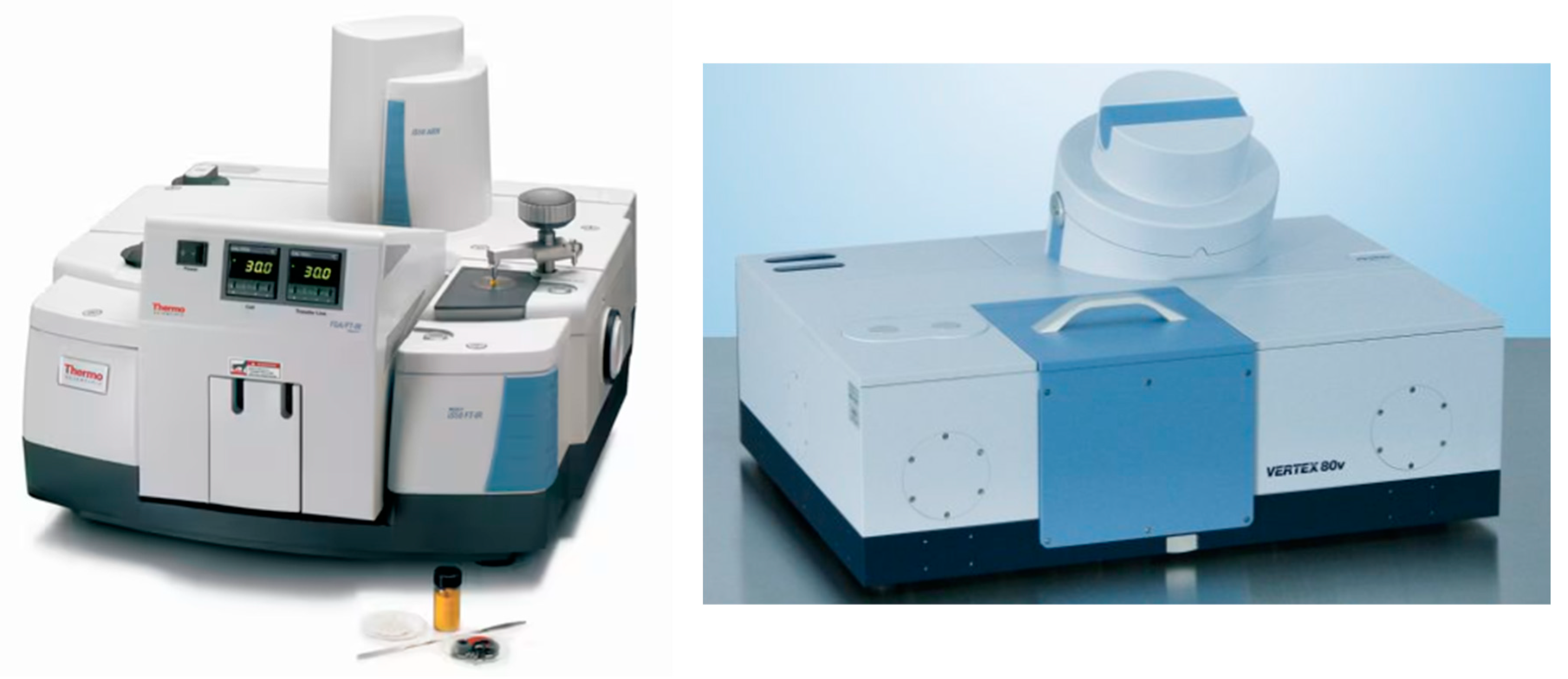
Figure 35.
Structural characterization by WAXD and FTIR. (a) BOPVDF films at room temperature are profiled using 1D WAXD, (b) The FTIR spectra analysis for the poled and fresh BOPVDF films in the transmission mode [214].
Figure 35.
Structural characterization by WAXD and FTIR. (a) BOPVDF films at room temperature are profiled using 1D WAXD, (b) The FTIR spectra analysis for the poled and fresh BOPVDF films in the transmission mode [214].
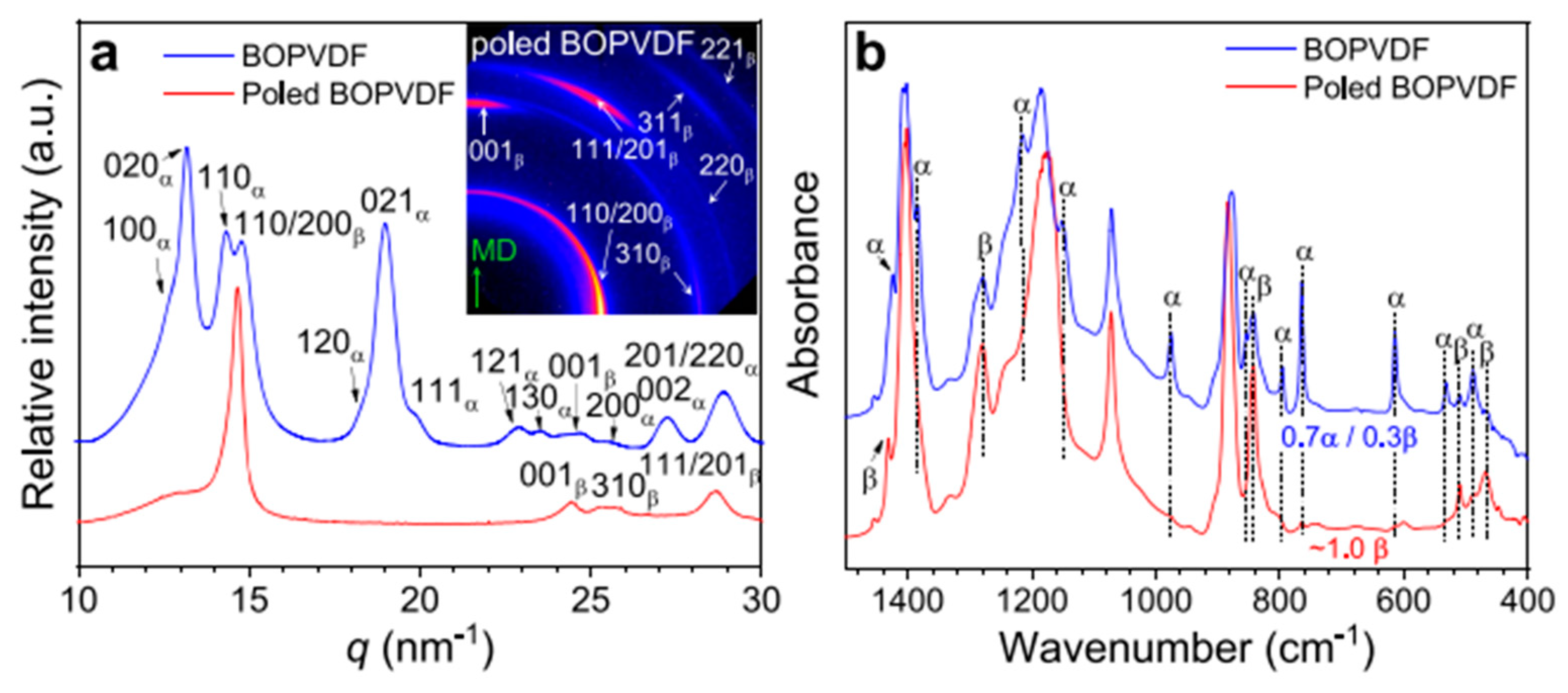
Figure 36.
Nano mechanical testing system Hysteron TI Premier II(www.Bruker.com).
Figure 36.
Nano mechanical testing system Hysteron TI Premier II(www.Bruker.com).
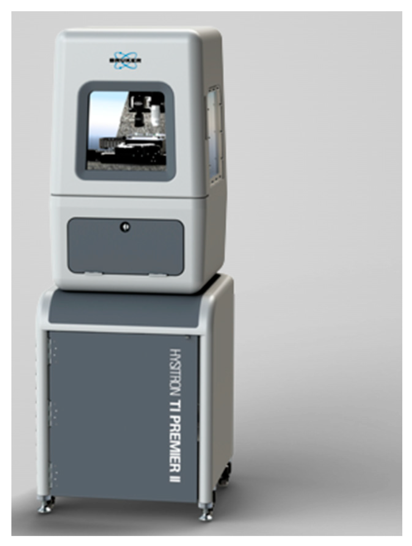
Figure 37.
The Model 5965 UTM are designed to perform tensile, compression etc (www.instron.com).
Figure 37.
The Model 5965 UTM are designed to perform tensile, compression etc (www.instron.com).
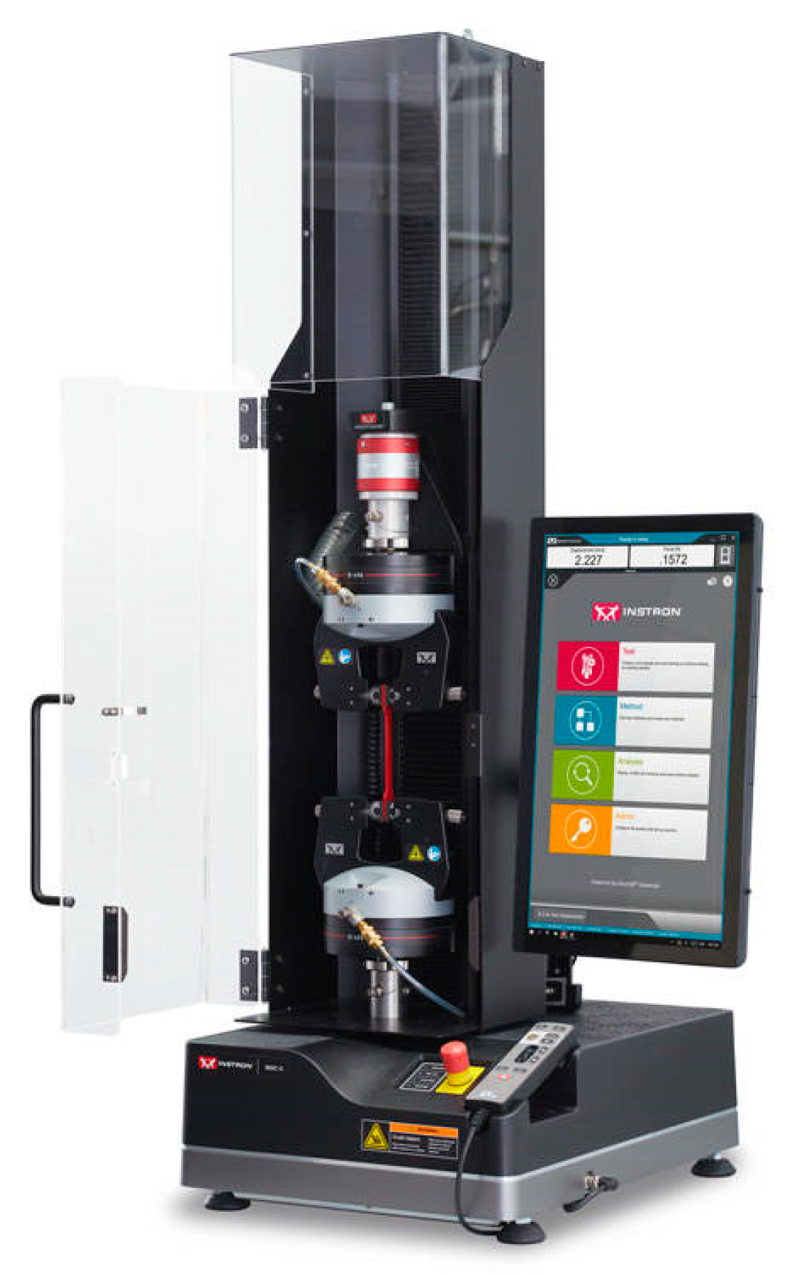
Figure 38.
Tensile strength testing Experimental setup [217].
Figure 38.
Tensile strength testing Experimental setup [217].
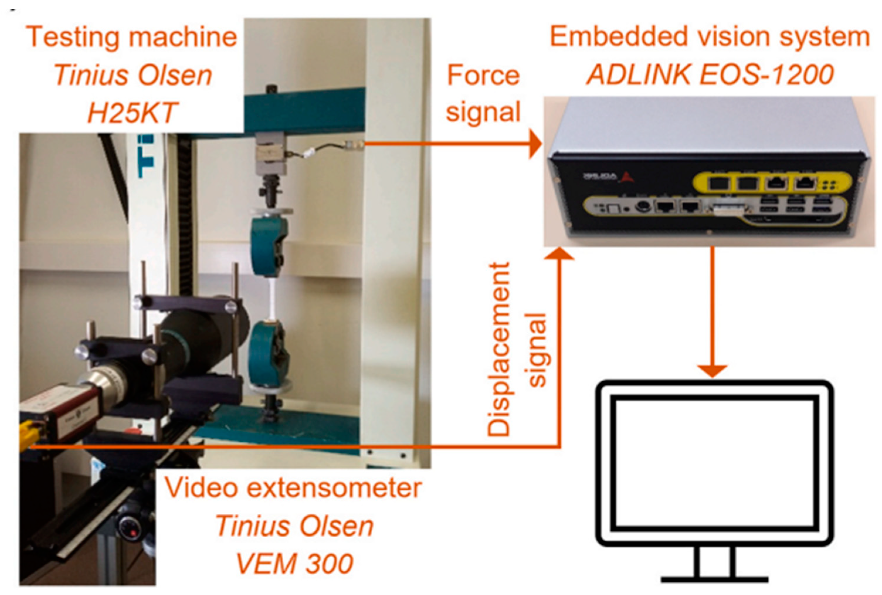
Figure 39.
Tensile Stress verses tensil strain curves of specimens printed with various crystalline patterns by using (a) PVDF-homopolymer and (b) PVDF-copolymer [217].
Figure 39.
Tensile Stress verses tensil strain curves of specimens printed with various crystalline patterns by using (a) PVDF-homopolymer and (b) PVDF-copolymer [217].
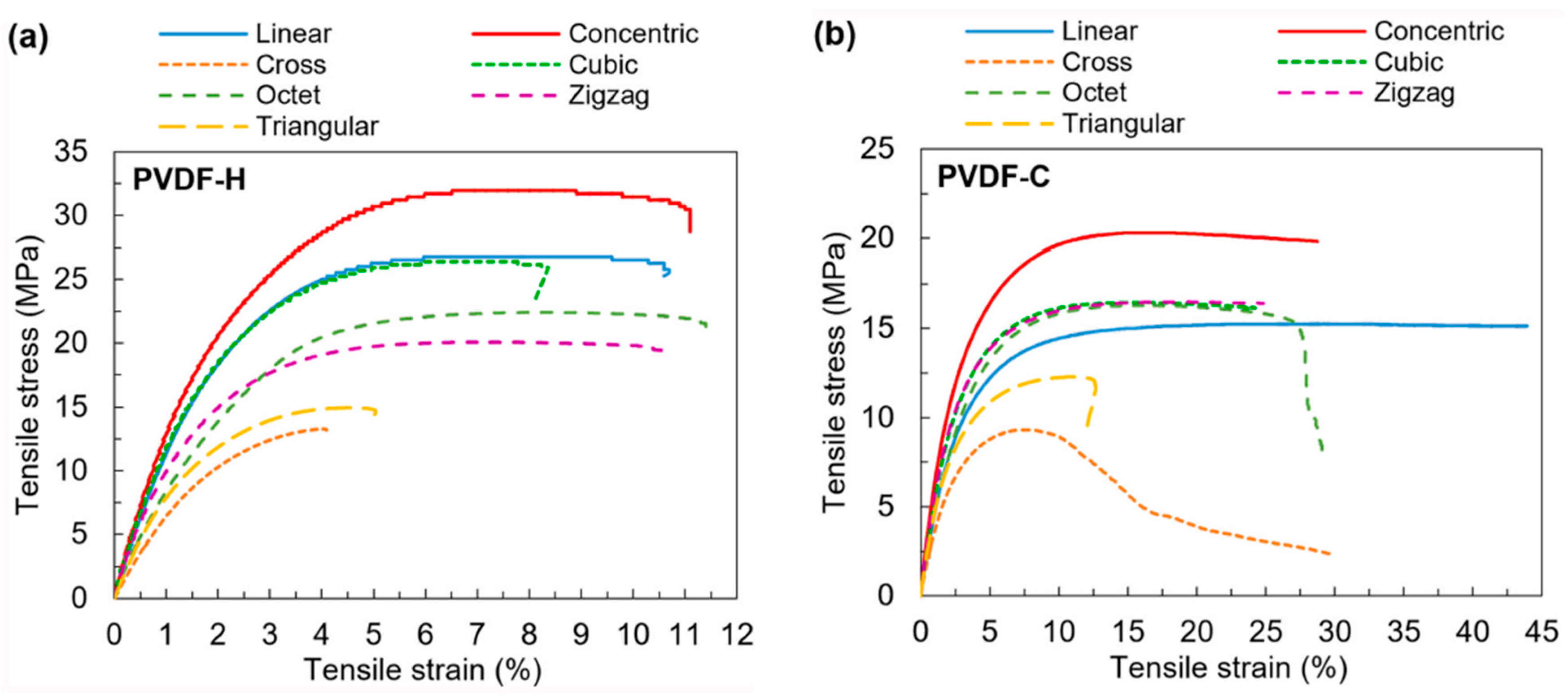
Figure 40.
Tensil test for highly poled PVDF film (a) Compression modulus (Y3) is obtained by nanoindentation, (b) tensile moduli (Y1 and Y2) are obtained from the stress-strain curves [214].
Figure 40.
Tensil test for highly poled PVDF film (a) Compression modulus (Y3) is obtained by nanoindentation, (b) tensile moduli (Y1 and Y2) are obtained from the stress-strain curves [214].
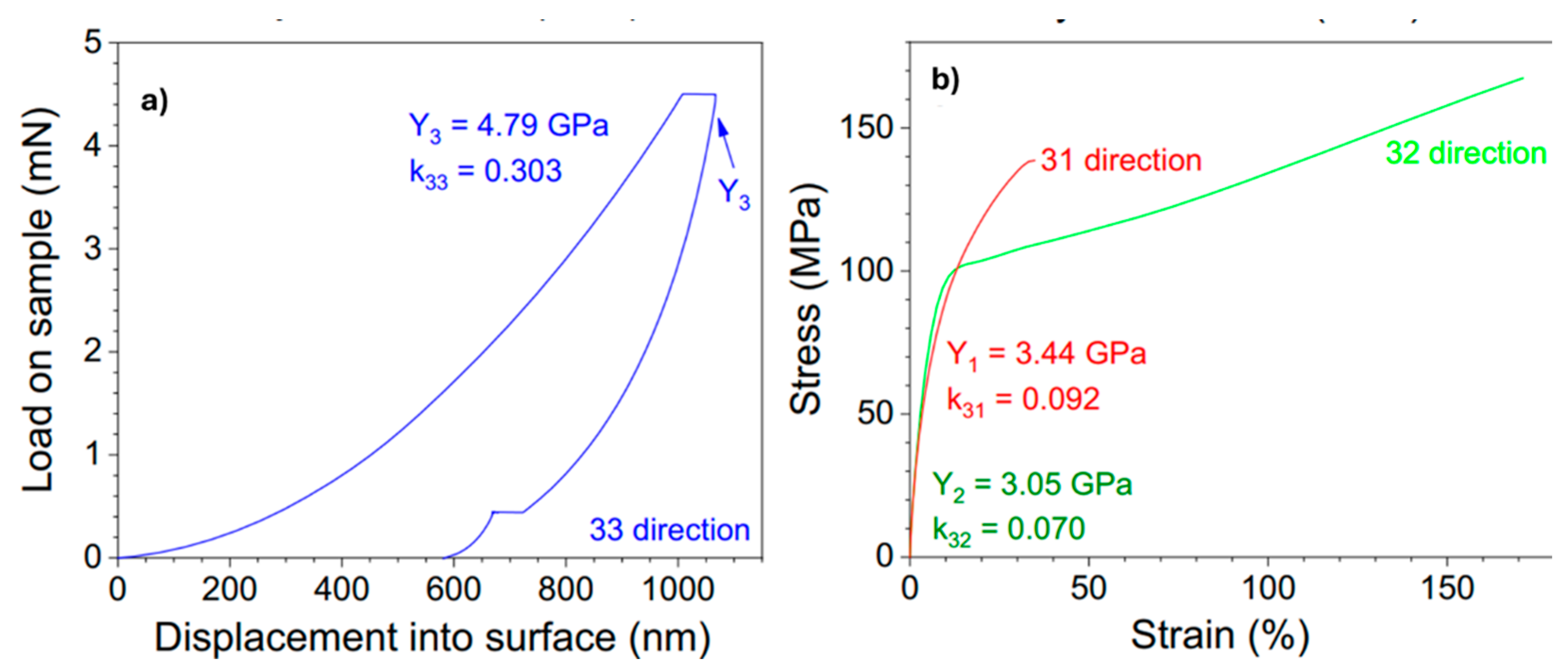
Figure 41.
The elastic modulus for both stretched and unstretched materials as a function of temperature. The data recorded at 1 and 10 Hz are represented by the dots and solid lines, respectively[218].
Figure 41.
The elastic modulus for both stretched and unstretched materials as a function of temperature. The data recorded at 1 and 10 Hz are represented by the dots and solid lines, respectively[218].
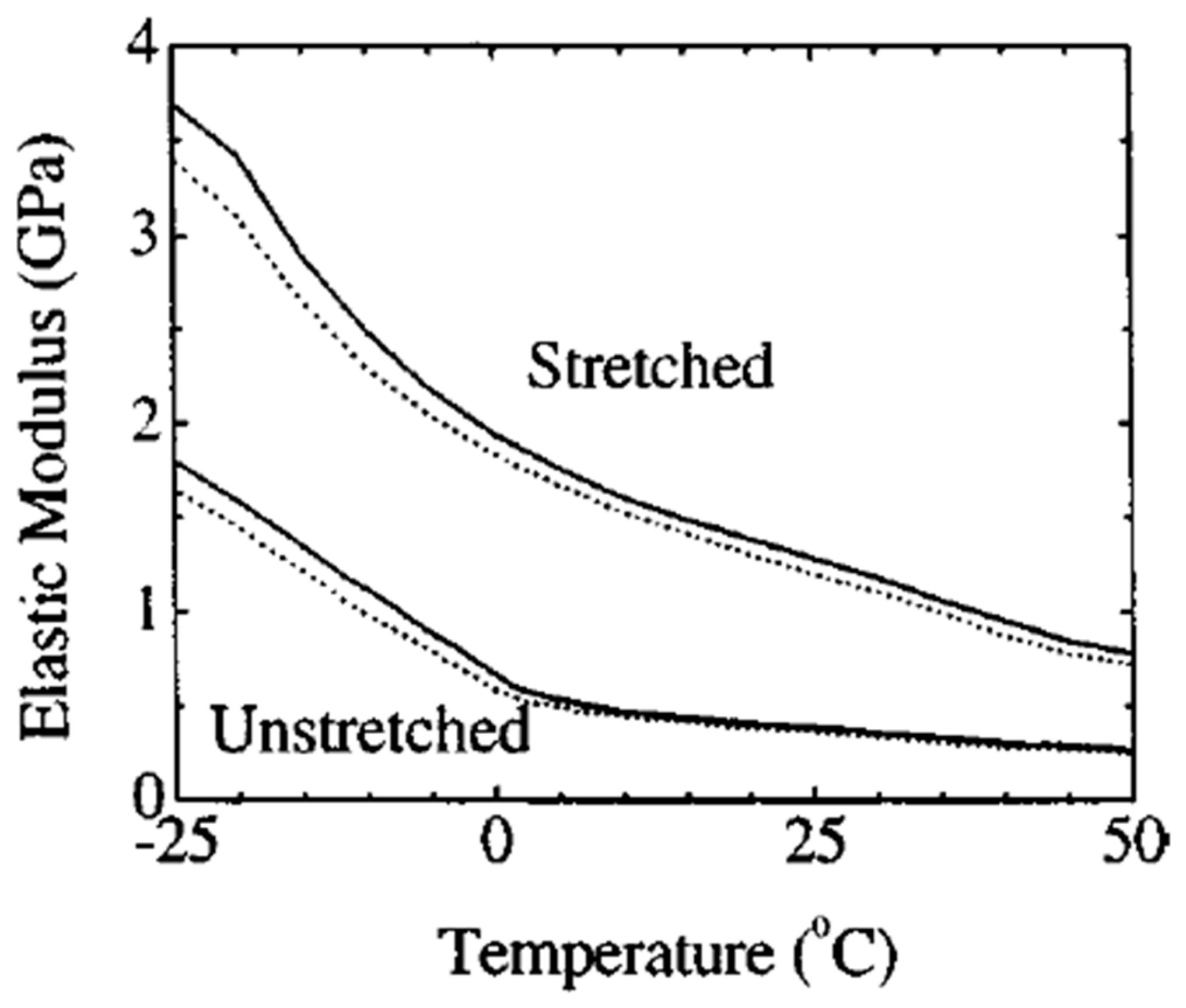
Figure 42.
Dielectric test system a test fixture along with dielectric material charge system[55].
Figure 42.
Dielectric test system a test fixture along with dielectric material charge system[55].
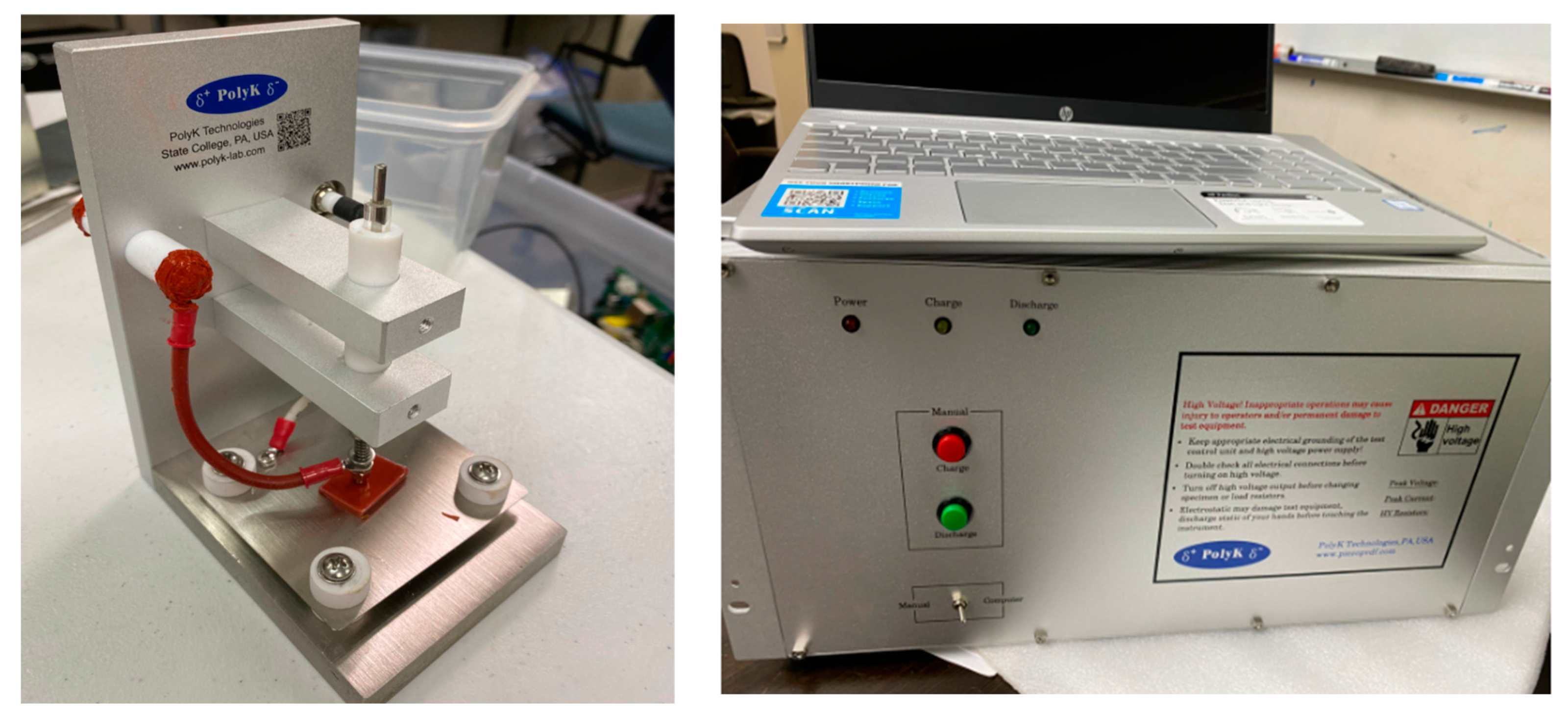
Figure 43.
Dielectric constant for various temperature of PVDF-TrFE-CFE [55].
Figure 43.
Dielectric constant for various temperature of PVDF-TrFE-CFE [55].
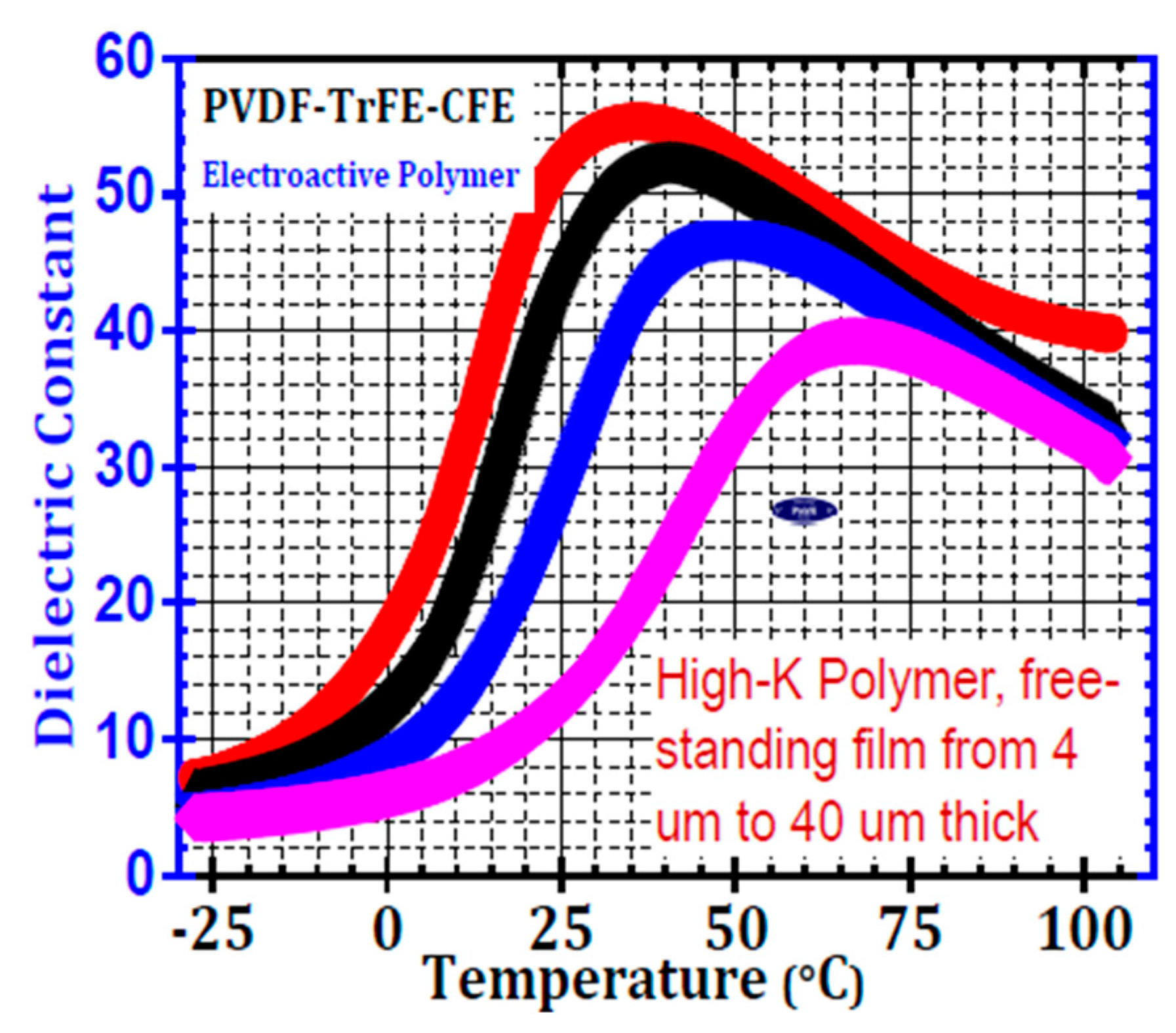
Figure 44.
Dielectric Material Charge Measurement System [55].
Figure 44.
Dielectric Material Charge Measurement System [55].
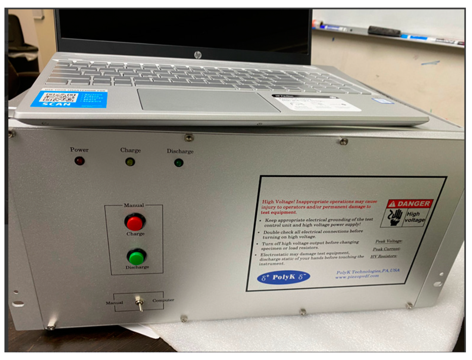
Figure 45.
Premier II Ferroelectric Test System (Radiant technology) www.ferrodevices.com.
Figure 45.
Premier II Ferroelectric Test System (Radiant technology) www.ferrodevices.com.
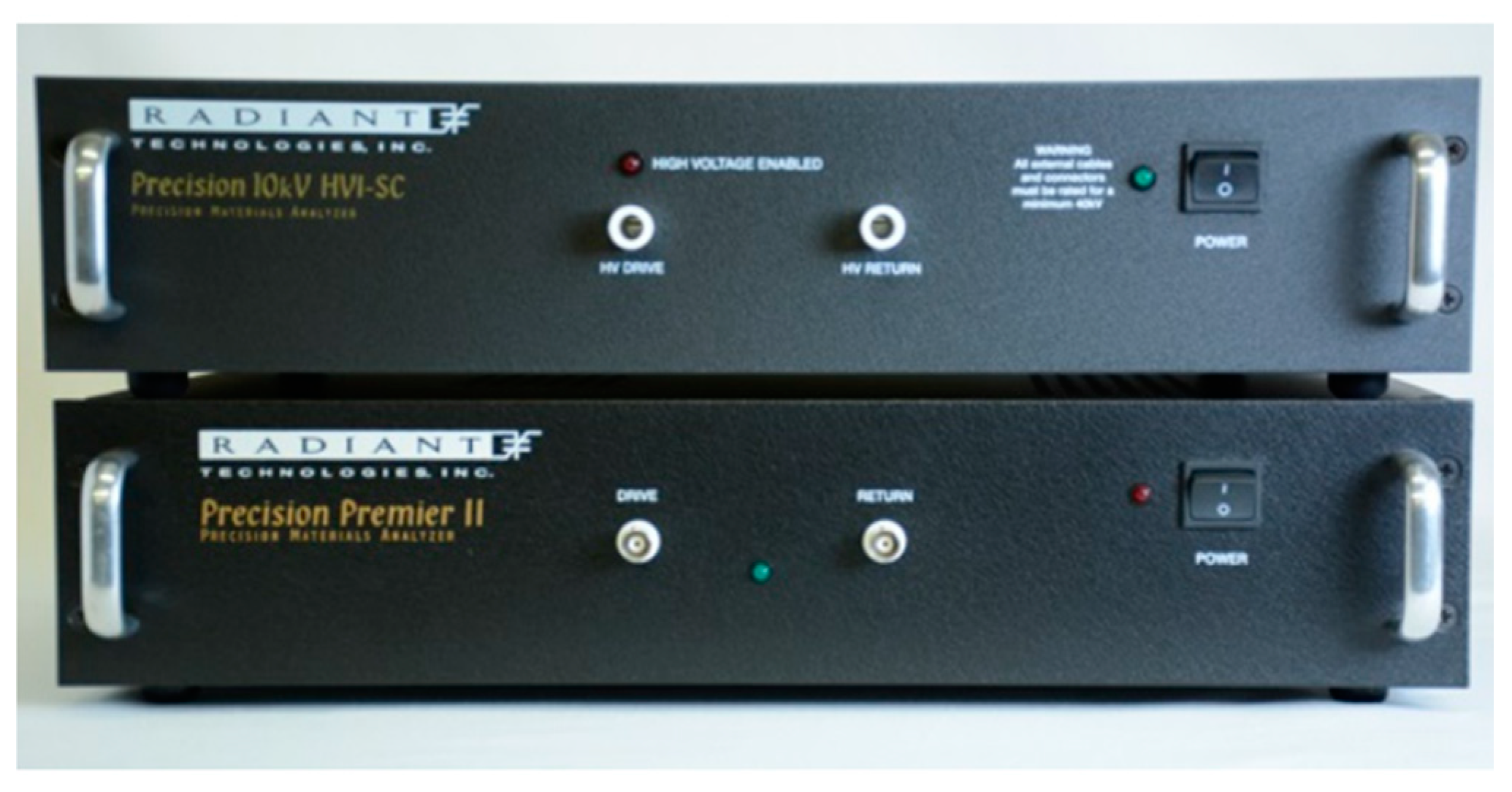
Figure 46.
P-E loop for commercial piezoelectric PVDF polymer provided by PolyK Technologies [55].
Figure 46.
P-E loop for commercial piezoelectric PVDF polymer provided by PolyK Technologies [55].
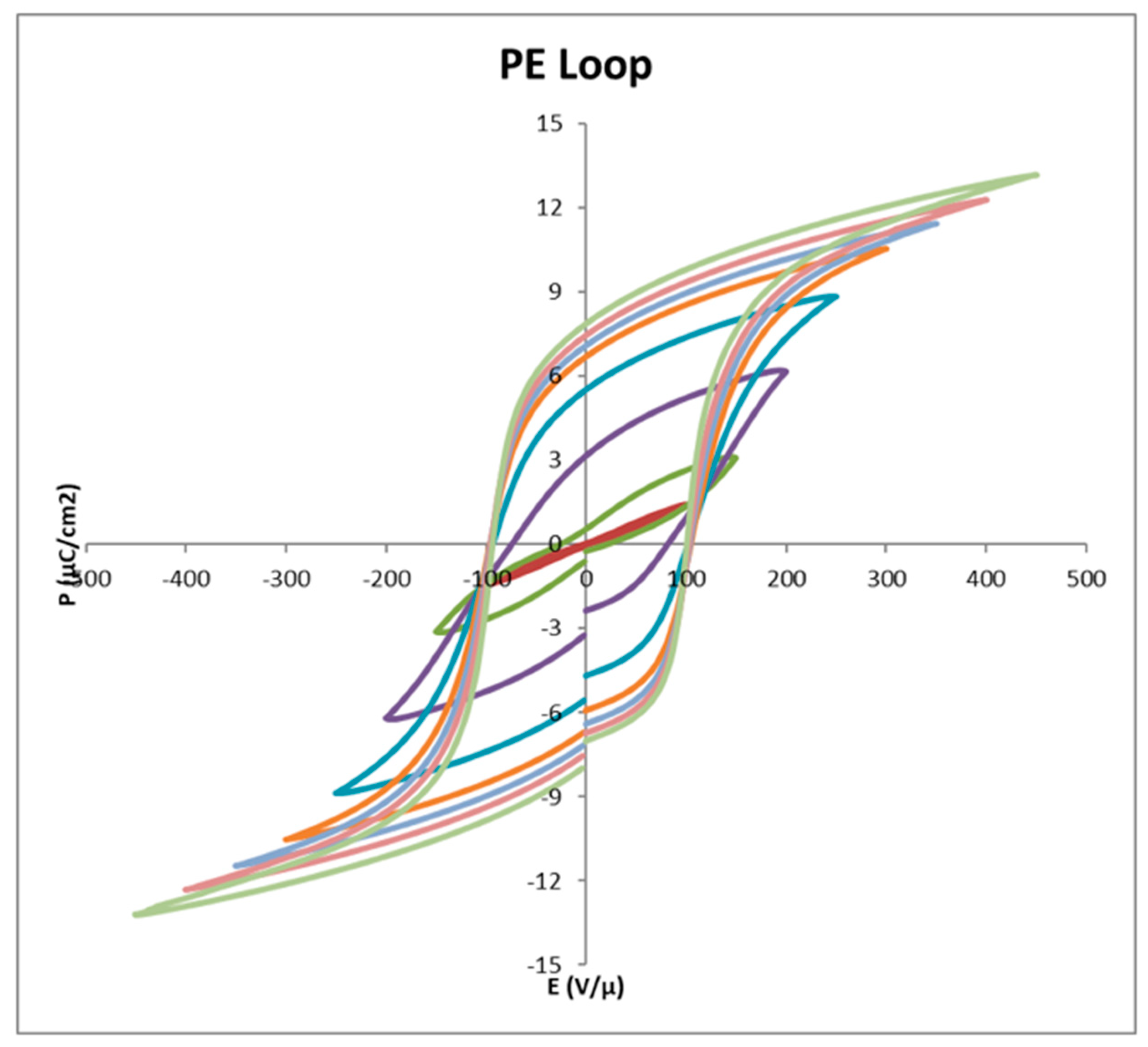
Figure 47.
Berlincourt Quasi Static d33 meter[55].
Figure 47.
Berlincourt Quasi Static d33 meter[55].
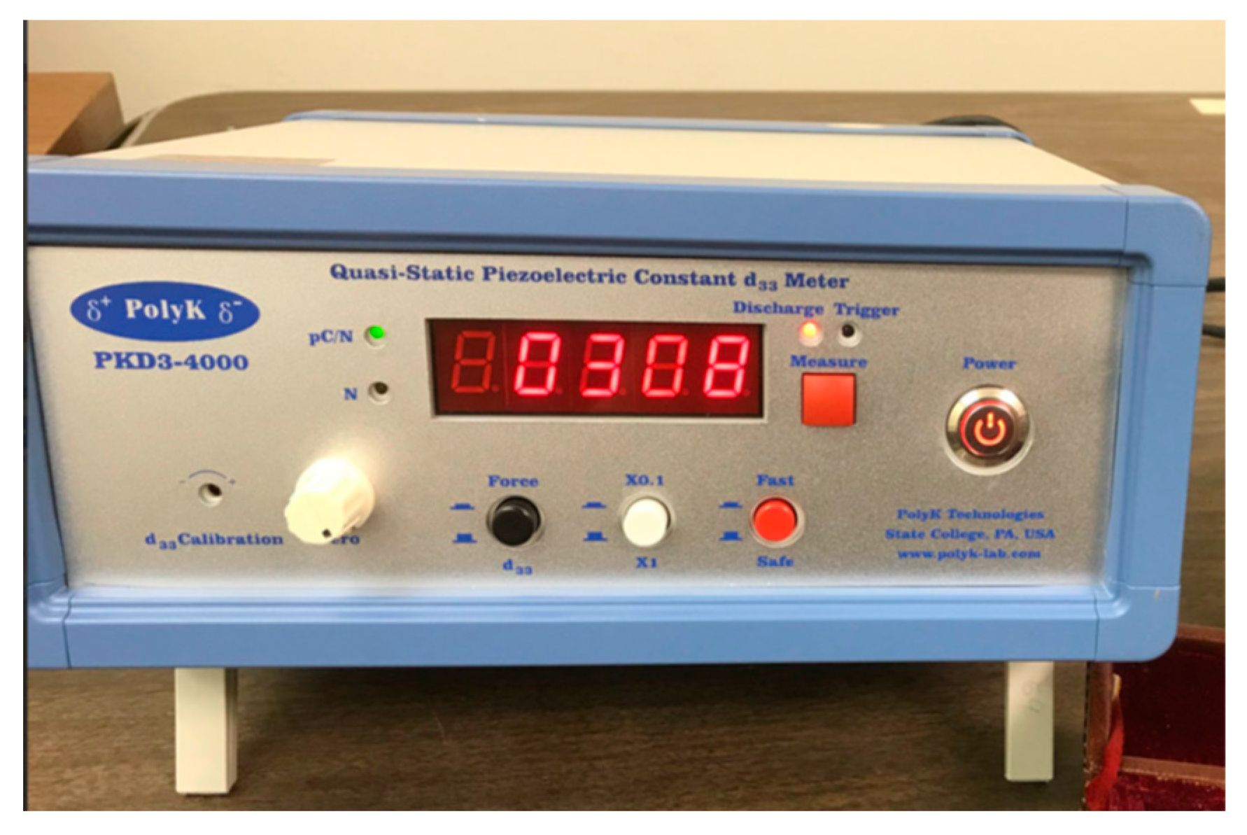
Figure 48.
Radiant's Thin Film Piezoelectric Test Bundle www.ferrodevices.com.
Figure 48.
Radiant's Thin Film Piezoelectric Test Bundle www.ferrodevices.com.
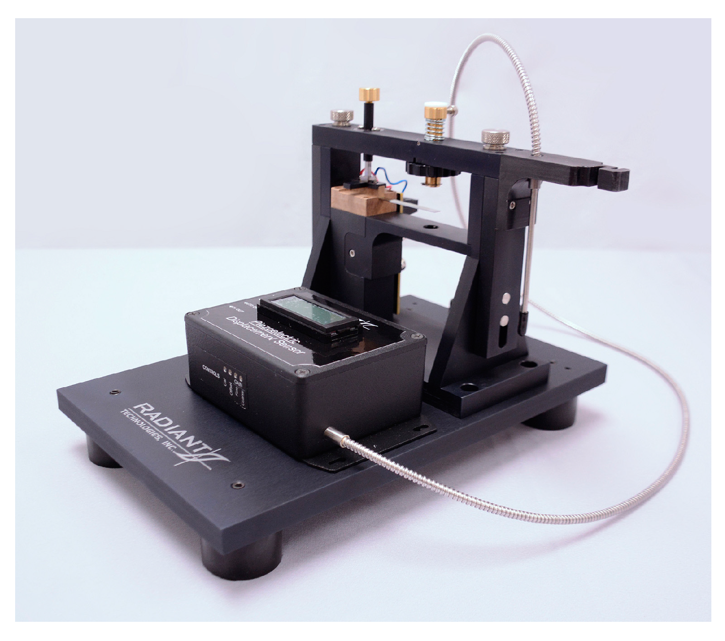
Figure 49.
Setup of quasistatic measurement for PVDF films.
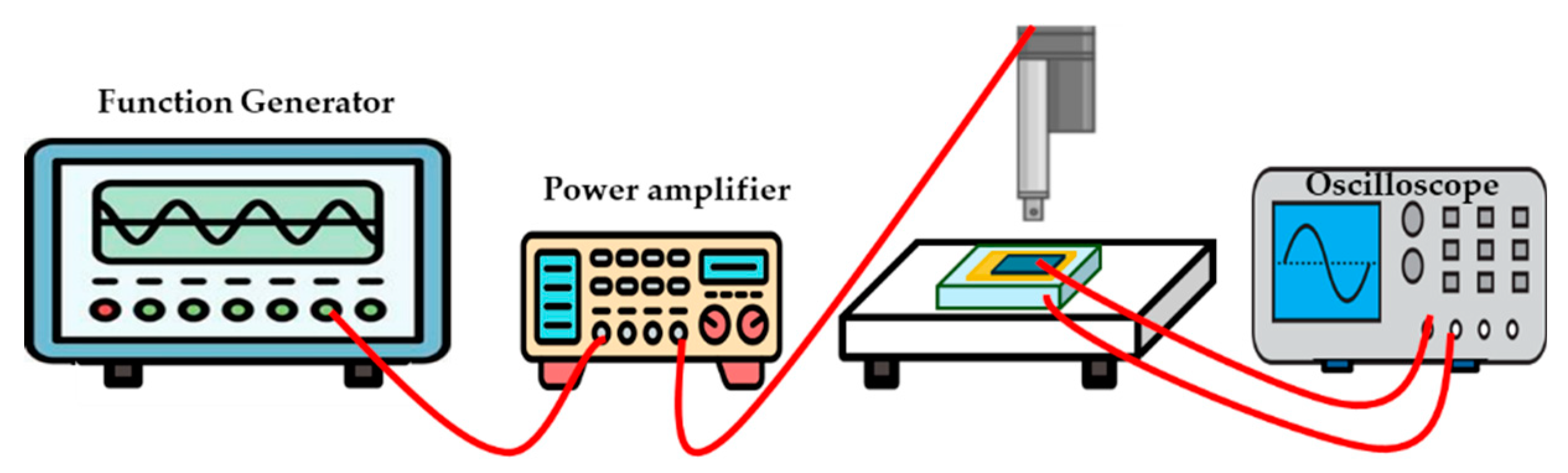
Figure 50.
A schematic diagram of high sensitivity, phase sensitive d33 meter system [219].
Figure 50.
A schematic diagram of high sensitivity, phase sensitive d33 meter system [219].
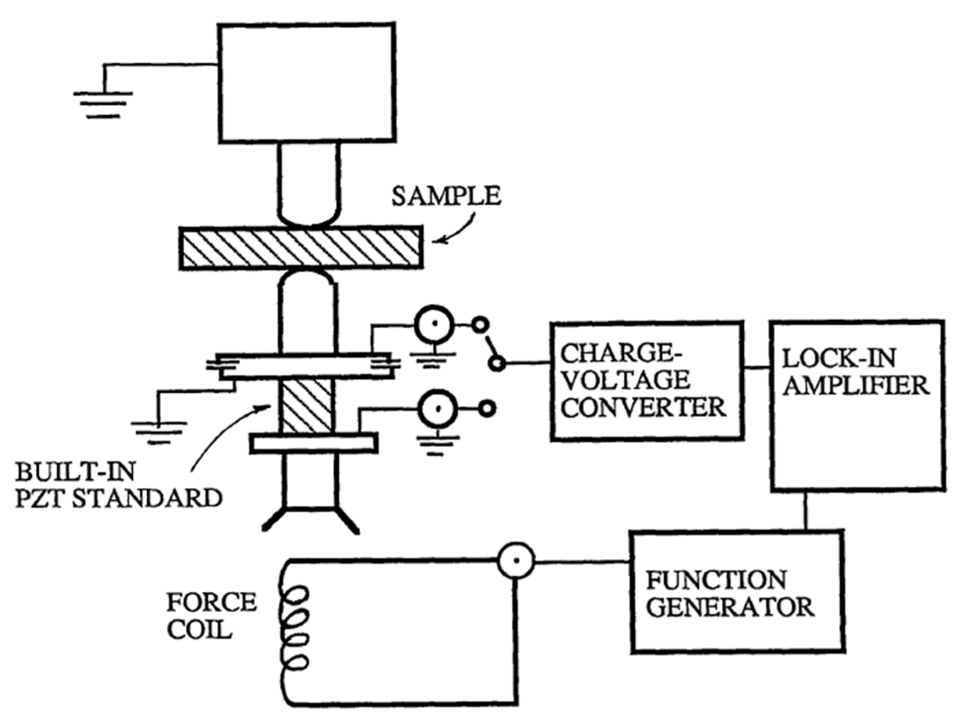
Figure 51.
Setup of dynamic measurement method.
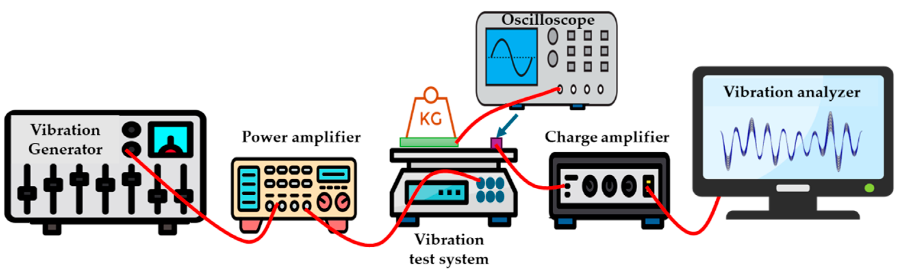
Figure 52.
Acoustic method experiment setup.
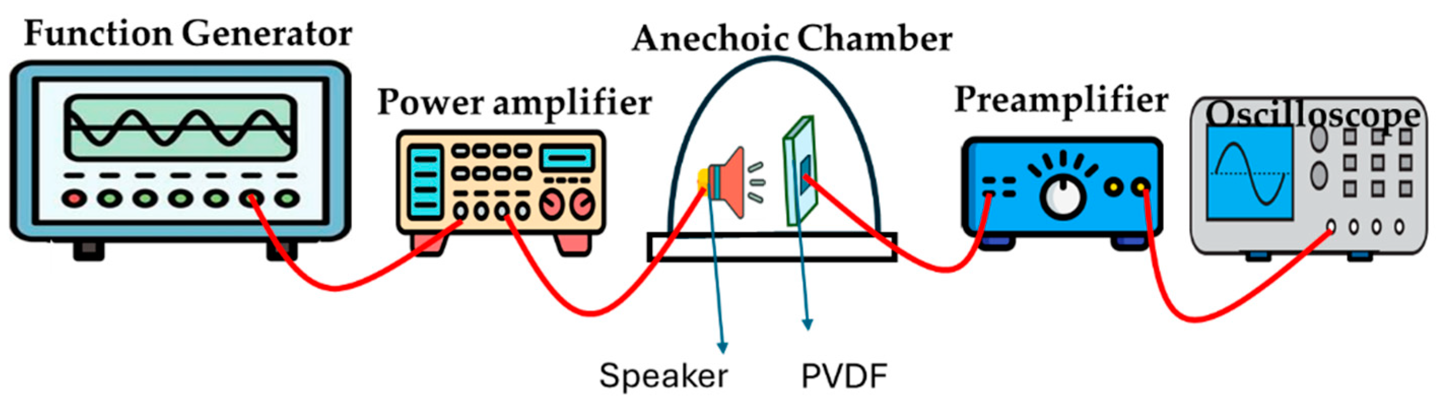
Figure 53.
Several piezoelectric coefficients for highly poled BOPVDF film (a) d33, (b) d31, d32 as a function of dynamic stress.[214].
Figure 53.
Several piezoelectric coefficients for highly poled BOPVDF film (a) d33, (b) d31, d32 as a function of dynamic stress.[214].
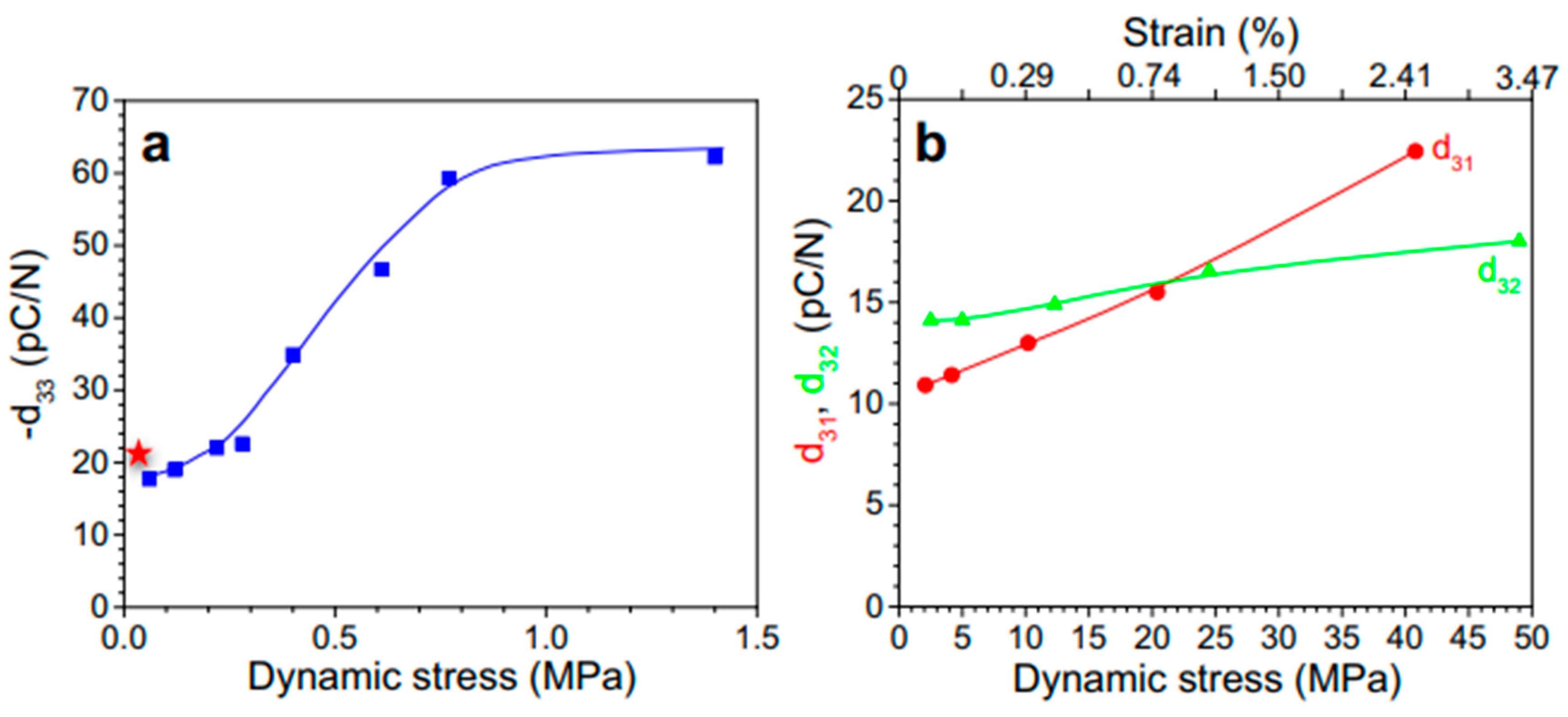
Figure 54.
Interferometric method setup.
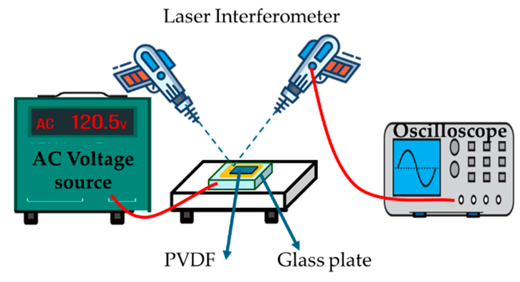
Figure 55.
Schematic diagram for PVDF strain measurement setup dilatometer based on the cantilever beam.[225].
Figure 55.
Schematic diagram for PVDF strain measurement setup dilatometer based on the cantilever beam.[225].
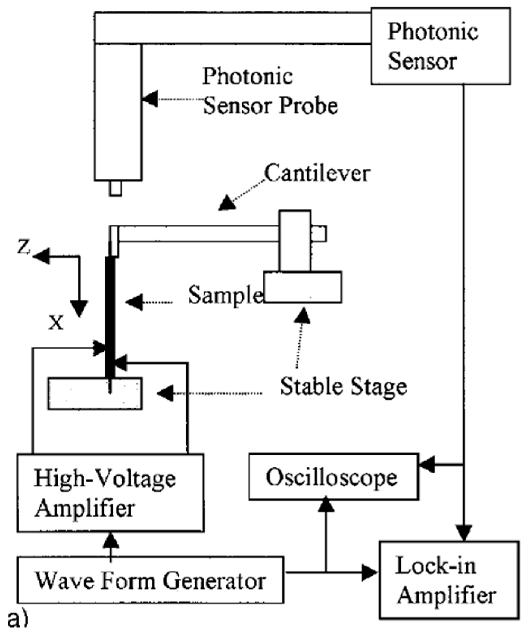
Figure 56.
Pure PVDF piezoelectric film's transverse strain at room temperature under various electric fields of 1 Hz.[225].
Figure 56.
Pure PVDF piezoelectric film's transverse strain at room temperature under various electric fields of 1 Hz.[225].
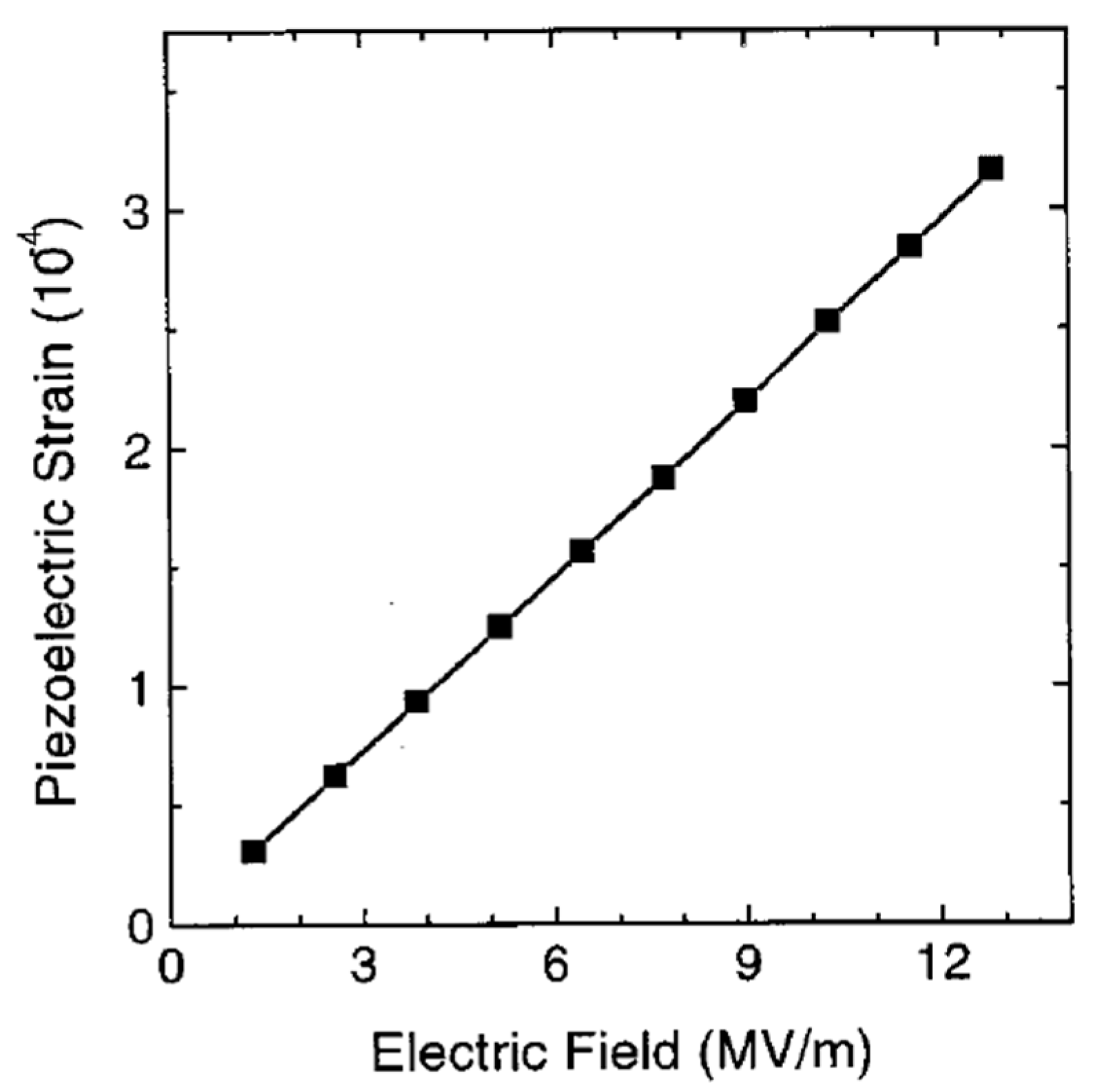
Figure 57.
Frequency dependence of the transverse strain caused by an electric field in a PVDF piezoelectric film.[225].
Figure 57.
Frequency dependence of the transverse strain caused by an electric field in a PVDF piezoelectric film.[225].
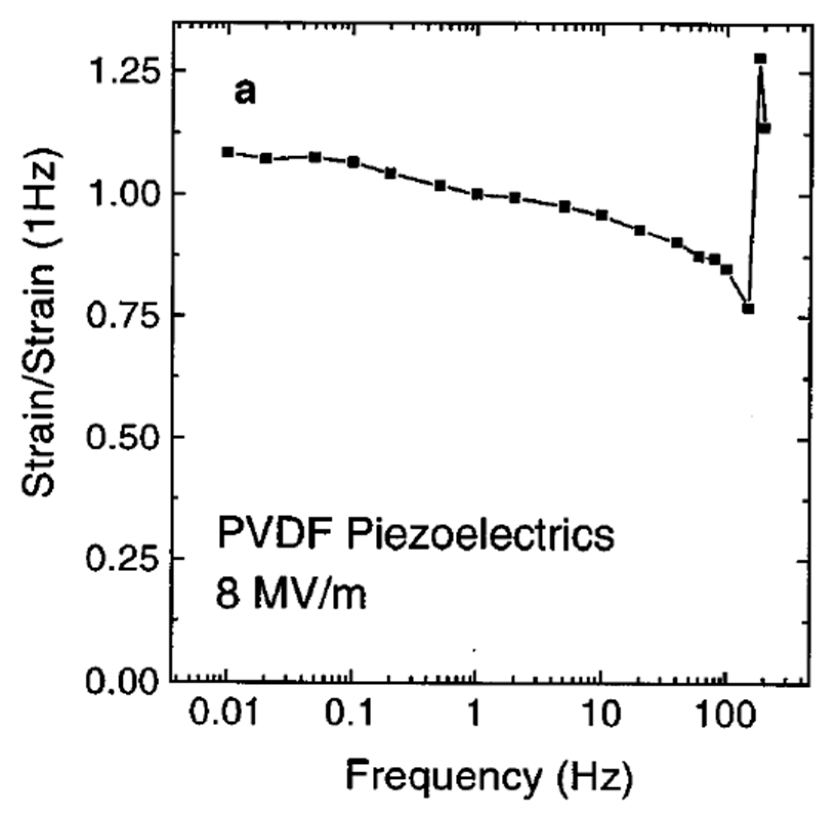
Figure 58.
Load effect on the electric field induced transverse strain response measured for PVDF-TrFE copolymer film, (a) Strain response as function of electric field for films under different loads b). Strain response and static load for films at various electric field strengths[225].
Figure 58.
Load effect on the electric field induced transverse strain response measured for PVDF-TrFE copolymer film, (a) Strain response as function of electric field for films under different loads b). Strain response and static load for films at various electric field strengths[225].
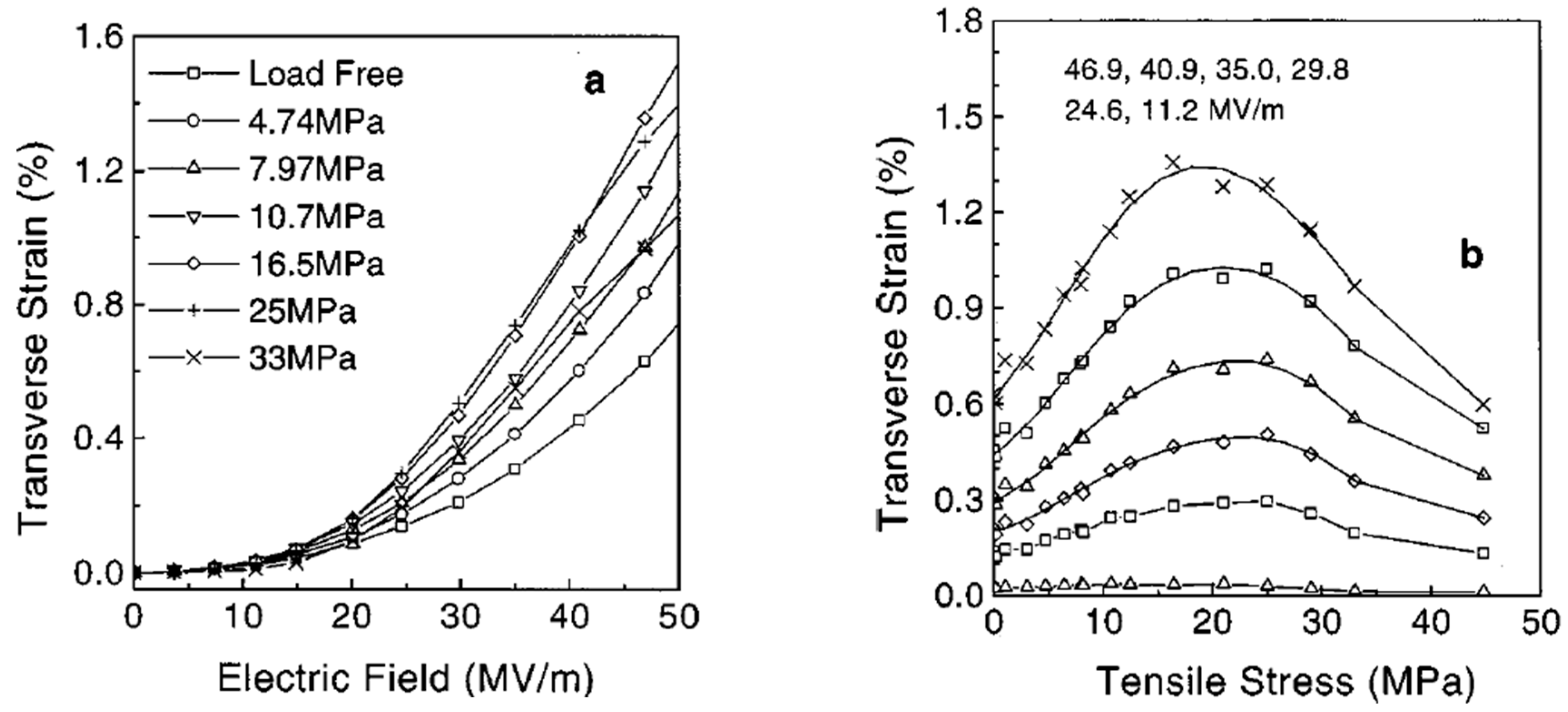
Figure 59.
The impedance as a function of frequency (a) the capacitance, and (b) the dielectric loss[227].
Figure 59.
The impedance as a function of frequency (a) the capacitance, and (b) the dielectric loss[227].
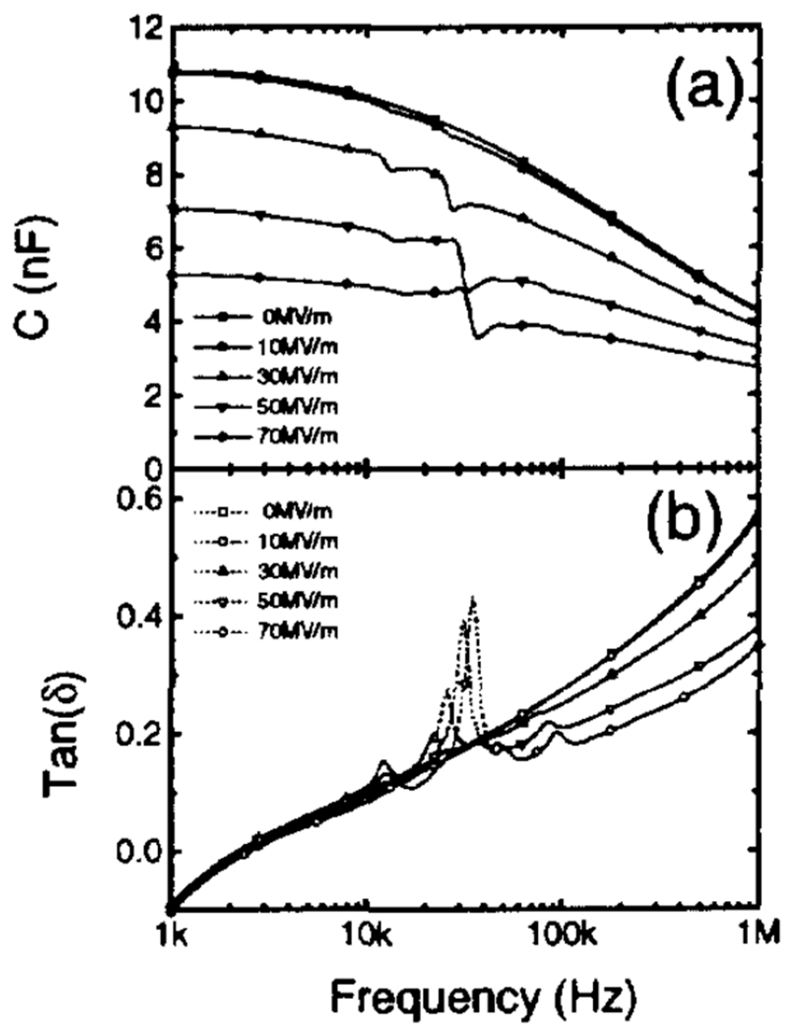
Figure 60.
Electromechanical coupling coefficient vs. dc-bias fields for the copolymer[227].
Figure 60.
Electromechanical coupling coefficient vs. dc-bias fields for the copolymer[227].
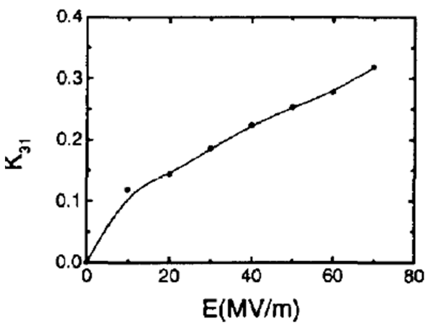
Figure 61.
The pyroelectricities of PVDF film with various wt% GO-doping [128].
Figure 61.
The pyroelectricities of PVDF film with various wt% GO-doping [128].
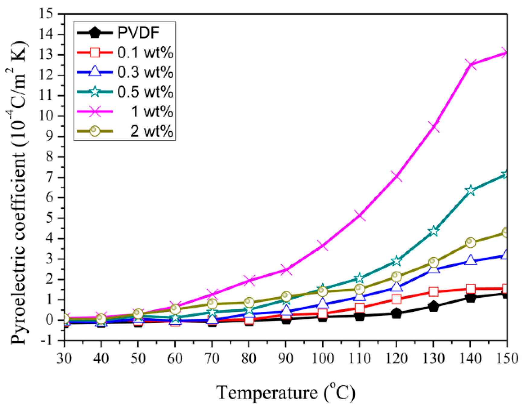
Figure 62.
The pyroelectric currents of PVDF film with various wt% GO-doping [128].
Figure 62.
The pyroelectric currents of PVDF film with various wt% GO-doping [128].
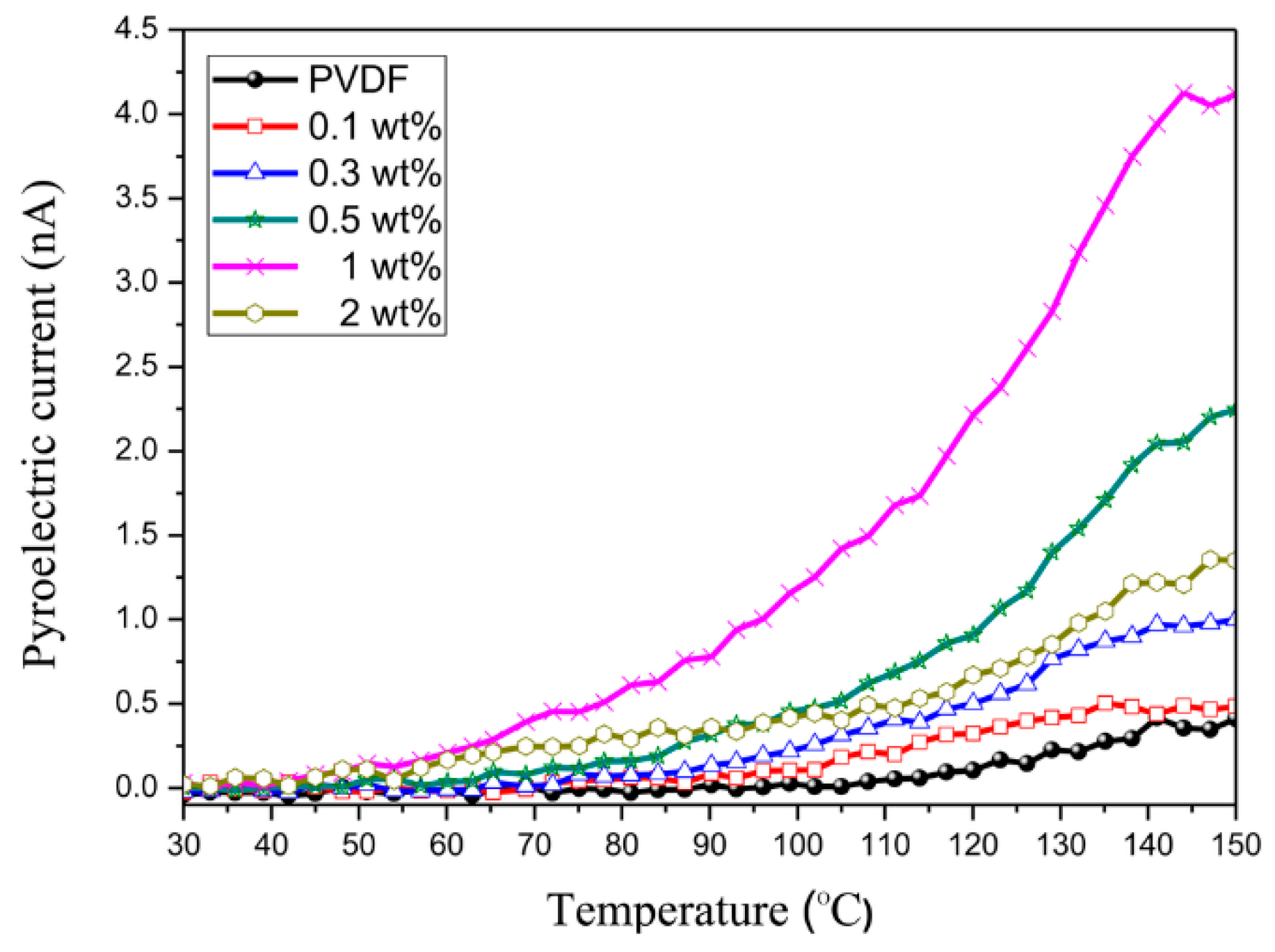

| Properties | Parameters | PVDF example values |
|---|---|---|
| Physical | Density (g/cm³) | 1.78 |
| Material color | transparent resin without color | |
| Water absorption % | 0.02 - 0.07 | |
| Refraction Index (ND) | 1.40 - 1.42 | |
| Oxygen Index (%) | 42 - 44 | |
| Mechanical | Tensile strength @ 23°C (MPa) | 35–55 |
| Hardness, Shore D | 50 - 80 | |
| Young’s modulus @ 23°C (MPa) | 1340–2000 | |
| Permittivity of free space(F/m) | ε0= 8.854*10-12 | |
| Elastic constant N/m2 | C11 =2.184*109 C12=0.633*109 |
|
| Piezoelectric | Curie temperature 80°C Strain constant d (10-12 C/N) |
d31 = 20–30 d33 = -30 |
| Stress constant (10-3 mV/N) | g33=335 | |
| Volume resistivity (Ω – cm) | 1015 -2.0 × 10¹⁴ | |
| Thermal | Melting Point °C | 177 |
| Defection temperature °C(261 psi) | 114–118 | |
| Flammability | V-O | |
| Thermal expansion coefficient(μm/m-°C) | 10-4 | |
| Decomposition Temp (°C) | 375 | |
| Thermal Conductivity (W/m - K) | 0.144 - 0.2 | |
| Glass transition temperature, °C | −35 | |
| Flammability°C | V-O |
| Chemical properties of PVDF | |||||
|---|---|---|---|---|---|
| Organic solvent resistance | Alcohol resistance | ||||
| Chemical | 20°C | 50°C | Chemical | 20 °C | 50 °C |
| Acetone | Not | Not | Benzyl alcohol (pure) | Yes | Yes |
| Chlorobenzene | Yes | Yes | Methanol | Yes | Yes |
| Benzene | Yes | Limited | Ethanol (30%) | Yes | Yes |
| Chloroform | Yes | Yes | Methyl alcohol (10%) | Yes | Yes |
| Diethylene glycol | Yes | - | Phenol (10%) | Yes | Yes |
| Cyclohexane | Yes | Yes | Methyl alcohol (pure) | Yes | Yes |
| Dimethyl formamide | - | - | Propanol | Yes | Yes |
| Trichloroethane | Yes | Yes | Phenol (100% | Yes | Yes |
| Diethylamino | Yes | Not | Resistance to acids and bases | ||
| Xylol | Yes | yes | Formic acid (10%) | Yes | Yes |
| Food product resistance | Acetic acid (100%) | Yes | Yes | ||
| Glucose | Yes | Not | Acetic acid (10%) | Yes | Yes |
| Milk | Yes | Yes | Hydrochloric acid | Yes | Yes |
| Olive oil | Yes | Yes | Sulfuric acid (10%) | Yes | Yes |
| Wine | Yes | Yes | Lactic acid | Yes | Limited |
| Vinegar | Yes | Limited | Nitric acid (10%) | Yes | Yes |
| Resistance to oils and fats | Nitric acid (Conc.) | Limited | Limited | ||
| Coconut oil | Yes | Yes | Hydrogen peroxide (90%) | Yes | - |
| Butyl acetate | Yes | Limited | Sulfuric acid (90%) | Yes | Yes |
| Mineral oils | Yes | Yes | Sulfuric acid (fuming/monohydrate) |
Not | Not |
| Pine oil | Yes | Yes | Trichlorofluoromethane | Yes | Yes |
| Paraffin oil | Yes | Yes | Tetrahydrofuran | Limited | Not |
Table 3.
Different fabrication methods along with their advantages, disadvantages and parameters of PVDF[66].
Table 3.
Different fabrication methods along with their advantages, disadvantages and parameters of PVDF[66].
| Method | Advantages | Disadvantages | Common Prameter |
| Solution Casting |
|
|
Concentration: 10-20 wt% Temperature: 25-80°C |
| Hot pressing |
|
|
- |
| Electrospinning |
|
|
Voltage: 10-30 kV Flow rate: 0.5-2 mL/h |
| Spin Coating |
|
|
Speed: 1000-5000 rpm Time: 30-60 s |
| Solution Coating |
|
|
Concentration: 5-15 wt% Temperature: 25-60°C |
| 3D Printing |
|
|
Layer height: 0.1-0.4 mm Speed: 10-100 mm/s |
Table 4.
The PVDF polymer's crystalline phase transformation methods along their adavantages and disadvantages.
Table 4.
The PVDF polymer's crystalline phase transformation methods along their adavantages and disadvantages.
| Methods | Advantages | Disadvantages |
| Stretching[68,171] |
|
|
| Annealing Treatment [155,161] |
|
|
| Poling[9,172] |
|
|
Table 5.
Advantages and applications of PVDF copolymers.
| Polymer | Advantage | Applications |
| PVDF |
|
|
| Poly (VDF-co-TrFE) |
|
|
| Poly (VDF-co-HFP) |
|
|
| Poly (VDF-co-CTFE) |
|
|
Table 6.
Advantages and applications of PVDF blend with polymers.
| PVDF blend with polymers | Advantage | Applications | Ref |
| PVDF/PMMA | promotes the formation of the β-phase |
|
[207,208] |
| PLLA/PVDF | Improved biodegradability |
|
[209,210] |
| PVDF/ ILs | - |
|
[211,212] |
Table 7.
The characterizations methods for various properties of PVDF.
| Properties | Characterization methods | Determining parameters |
|---|---|---|
| Thermal characterization | Differential Scanning Calorimetry (DSC) | Melting point, Glass transition temperature, Crystallization temperature. |
| Thermogravimetric Analysis (TGA) | Thermal stability, Degradation behavior. |
|
| Structural characterization | X-ray Diffraction (XRD) | Crystal phases (α, β, γ), Crystallinity percentage. |
| Fourier Transform Infrared Spectroscopy (FTIR) | Characteristic peaks of various crystal phases. | |
| Mechanical characterization | Universal testing machine(UTM) | Tensile strength, Young's modulus, Elongation at break. |
| Dynamic Mechanical Analysis (DMA) | Viscoelastic behavior, | |
| Electrical characterization | Dielectric Spectroscopy | Dielectric constant, Loss tangent over frequency. |
| Conductivity Measurements | Electrical conductivity. | |
| Dielectric | Impedance Analyzer | Dielectric constant, Loss tangent as a function of frequency. |
| Ferroelectric characterization | Ferroelectric Loop Tracer | Polarization-electric field (P-E) hysteresis loops. |
| Switching Spectroscopy | Domain switching dynamics. | |
| Electromechanical characterization | Strain Gauge | Strain generated by electric field. |
| Laser Interferometry | Displacement due to electric field. | |
| Piezoelectric characterization | d33 Meter | Piezoelectric charge coefficient (d33). |
| Piezo response Force Microscopy (PFM) | Piezoelectric domains, Piezoelectric coefficients. | |
| Pyroelectric characterization | Pyroelectric Current Meter | Pyroelectric current caused by temperature variation. |
| Electrocaloric Effect Measurements | Temperature change induced by electric field. |
Disclaimer/Publisher’s Note: The statements, opinions and data contained in all publications are solely those of the individual author(s) and contributor(s) and not of MDPI and/or the editor(s). MDPI and/or the editor(s) disclaim responsibility for any injury to people or property resulting from any ideas, methods, instructions or products referred to in the content. |
© 2025 by the authors. Licensee MDPI, Basel, Switzerland. This article is an open access article distributed under the terms and conditions of the Creative Commons Attribution (CC BY) license (http://creativecommons.org/licenses/by/4.0/).
Copyright: This open access article is published under a Creative Commons CC BY 4.0 license, which permit the free download, distribution, and reuse, provided that the author and preprint are cited in any reuse.


