
Submitted:
31 December 2024
Posted:
02 January 2025
You are already at the latest version
Abstract
Novel Ni/SBA-15 catalysts were synthesised and their activity in the dry reforming of methane process was assessed. Extrudates, in the shape of pellets, of these materials were prepared and tested in a pyrolysis pilot plant fitted with a catalytic reactor for the sewage sludge pyrolysis tar removal. The Ni/SBA-15 catalyst pellets remained highly active and stable throughout the test duration, converting 100% tar in the hot gas to smaller non-condensable gases, thereby increasing the pyrolysis gas fraction and eliminating the problematic tar in the vapour stream. Catalyst characterisation with Scanning Electron Microscope (SEM), Energy Dispersive X-ray (EDX) analysis, Transmission Electron Microscope (TEM) and Thermogravimetric Analysis (TGA) confirmed that both, the Ni/SBA-15 powered catalyst and the pellets as well, were resistant to sintering and carbon deposition and remained highly active even with relatively high-level sulphur in the feed stream. The Ni/SBA-15 catalyst extrudates were prepared by mixing the powdered catalyst with varied amounts of colloidal silica binder and fixed amounts of methyl cellulose and water. The highest mechanical strength of the extrudates was determined to be for those obtained with 36% of the inorganic binder. The physical properties and catalytic activity of Ni/SBA-15 pellets with 36% colloidal silica was compared with the original powdered Ni/SBA-15 catalyst after crushing some of the pellets to powder to determine any binder inhibitory effect. The results confirm that colloidal silica binder did not inhibit the desired catalyst properties and performance in the reaction. Instead, an enhanced catalytic performance was observed.
Keywords:
tar cracking
; novel Ni/SBA-15 catalyst
; pyrolysis
; sewage sludge
; liquid fraction
; gas fraction
; sustainability
; pilot plant
1. Introduction
As urban population continues to grow, wastewater treatment plants across the globe are facing greater challenges in the management and disposal of their increasing sewage sludge—a solid residue with about 60–70% organic content, in addition to some inorganic materials and heavy metals produced after wastewater treatment from their facilities. More stringent government legislations to protect the environment from exposure to hazardous wastes means that the water treatment plants will have to operate a more efficient waste management system. For instance, the European Union Urban Waste Water Directive 91/271/EEC which was amended by 98/15/EC completely phased out the dumping of sewage sludge into the sea and other water bodies by member countries, via ships, pipelines or by any other means [1]. There is also a significant reduction by the EU in the emission of dioxins permitted by incineration. Disposal of sewage sludge in landfills by trucks, another means of waste disposal, is capital intensive and studies show that many landfill sites release uncontrolled methane, a prominent greenhouse gas, into the atmosphere which causes wild land fires and global warming [2,3,4,5,6].
The European Union’s response to waste management challenge is demonstrated in their target to reduce waste disposal by 50% in 2050 through waste recovery reuse, recycling and energy recovery in addition to other measures, and they strongly recommend thermochemical waste conversion by pyrolysis/gasification to energy production as a potentially sustainable route to manage waste disposal [7].
Pyrolysis is an irreversible thermochemical decomposition of organic materials at temperatures between 300 and 900°C in the absence of oxygen or air, where large complex hydrocarbon molecules of the organic matter break down to smaller and simple molecules of gas, liquid and solid [8,9]. Gasification is also a thermochemical decomposition of organic materials but in the presence of oxygen or air [10,11,12]. The major advantage of pyrolysis over gasification is that highly toxic gases such as furans and dioxins are absent as the oxygen required for their formation is absent in pyrolysis [13].
Dried sewage sludge has a much higher heating value (12,000–20,000 kJ/kg) compared to wet sewage sludge (1000–3000 kJ/kg), and so, the sludge is usually dried before pyrolysis [14].
The gas fraction from pyrolysis of organic matter contains non condensable gases, mainly hydrogen, methane, carbon monoxide, carbon dioxide and some low molecular weight hydrocarbons. The liquid fraction contains water and condensable low-grade bio-oil, also referred to as tar, which consists of many complex organic compounds such as aliphatic, mono-aromatic, polycyclic aromatic hydrocarbons (PAHs), oxygenated hydrocarbons, organo-nitrogen compounds etc. The solid portion contains char and ash with heavy metals present [15,16,17,18,19]. The distribution of gas, liquid and solids depends on the nature of biomass and the operating conditions used in pyrolysis, especially temperature, heating rates and residence time in the reactor. For instance, higher temperatures and longer residence time in the reactor maximises gas production, while lower temperature and shorter residence time in the reactor maximises solid formation. Flash pyrolysis, where the organic matter is quickly heated between 350–500°C in 2 seconds, maximises oil production [20,21,22,23,24,25].
Many researchers have tried to upgrade the oil from pyrolysis of sewage sludge to high quality bio-crude. But the upgrading process is cumbersome, expensive and, in most cases, less effective [26,27,28,29,30]. A more viable option may be to remove the tar from the gas stream either by absorption, condensation, thermal or catalytic cracking and use the purified gas for production of chemicals or electricity generation. Liquid absorbents can be used to clean-up gas contaminated with tar and other pollutants such as hydrogen sulphide and hydrogen chloride to meet high quality gas requirements for internal combustion engines and gas to liquid technology. However, such wet cleaning processes leave behind large volumes of toxic liquid wastes which are difficult to purify or dispose [31,32]. An innovative approach therefore may be to crack the oil fraction or tar to non-condensable gases such as hydrogen, carbon monoxide, and methane; this way, only two fractions, gas and solids (chars) are produced [33]. The char can be used as agricultural fertilizer, carbon black or a commercial process can be explored to extract the valuable metals present. Tar cracking has the advantage of increasing the volume of the gas fraction while eliminating the problematic tar in the gas stream known to cause fouling and blockage of downstream equipment [34]. Tar cracking could be thermal or catalytic. Thermal cracking involves heating the liquid fraction at temperatures higher than 1000°C, which is commercially unattractive [35,36]. Alternatively, catalytic cracking occurs at temperatures lower than 800 °C. In fact, the hot gas from the pyrolysis reactor can be channelled directly to a catalytic chamber which would save the cost of heating another plant unit. However, it is quite difficult to manufacture a technical catalyst able to convert nearly all the oil fraction to gas without rapid catalyst deactivation from carbon deposition and catalyst sintering at high temperatures [37,38,39,40,41,42].
What is more, the solid catalyst used for tar cracking can also serve as an adsorbent to remove low levels of H2S and HCl present in the vapour stream.
Although significant progress has been made to develop, via design and preparation at laboratory scale, of biomass/waste tar cracking and reforming catalysts with high performances, mostly catalysts based on supported Ni or Co particles into supports with high specific surface area [43], their scale up and implementation at commercial level has not been as successful. The major challenges in scaling up the research, or laboratory-developed catalysts to technical ones, are attributed to their differences in composition, structure, and porosity along with commercial aspects such as cost, performance and safety [44]. The knowledge about the scaling up and shaping of powder catalysts is rather scarce in literature. For most of the academic researchers the topic is not of interest, as it is considered more of practical one. Shaping is mostly performed in industry by simply trial and error techniques. The catalyst manufacturing technologies are often not patented but kept secret. The shape and size of the catalyst particles should promote catalytic activity, control the mass transport through a catalyst bed, influence the bed pressure drop, and strengthen the particle resistance to crushing and abrasion. The choice of the shape and size is mainly driven by the type of reactor. Industrial catalysts are generally shaped in rings, spheres, tablets, and pellets, through various shaping techniques, as, for example, extrusion, pelletizing, granulation, oil drop method or spray-drying. The shaping of powdered active materials (i.e., catalysts, supports, adsorbents, etc.) usually requires not only the use of appropriate technology and equipment but also binders and other additives to improve the final properties of the product.
The absence of a suitable catalyst for tar cracking in hot gas is a major drawback to the full-scale commercialisation of the process.
We have developed, characterised and tested Ni-based powdered catalysts supported on SBA-15 mesoporous silica for dry reforming of methane, as a model reaction for catalytic tar reforming. As a result of their high surface area, ultrafine nickel particles strongly attached and highly dispersed on hydrothermally stable support, the high activity and stability of these catalysts encouraged us to attempt their scaling up and palletisation, followed by the characterisation of the pellets and testing in a pilot plant.
To the best of our knowledge, there are no reports in literature on the manufacture and use of Ni/SBA-15 pelletized catalysts.
The pellets were tested in a catalytic reactor connected to the Spirajoule® Pyrolyser from Biogreen® at ETIA pilot plant facility (https://etia-group.com/).
Dried sewage sludge pyrolysis was carried out at 800°C and the derived raw hot gas was passed over a non-heated catalytic reactor to ascertain the possibility of direct catalytic tar cracking after pyrolysis. The effect of catalyst on the volume and composition of the gas fraction was assessed by comparing the results with those obtained via pyrolysis of the same sewage sludge batch, also at 800°C, but without the catalytic reactor present. Fresh and spent catalysts used in the study were also characterised to investigate the effect of tar cracking on the Ni/SBA-15 catalyst pellets. Dry reforming of methane performed at laboratory scale in a micro-reactor was used to compare the catalytic performance of crushed Ni-SBA-15 catalyst pellets with the powdered Ni-SBA-15 catalyst. This was to observe any differences in catalytic performance resulting from the introduction of the chosen binders for the production of the Ni-SBA-15 catalyst pellets.
2. Experimental
2.1. Catalyst Preparation
About 1.5g of prepared SBA-15 [45] was placed in a beaker with 20 ml deionised water and stirred for 30 mins at room temperature before cooling to 5°C, while stirring. Few drops of NH4OH were added to the SBA-15 solution to raise the pH to 12.
In another beaker, [Ni(NH3)6] 2+ complex was synthesised by placing 1g of nickel acetate tetra hydrate (9.998%, Sigma Aldrich) in 10ml deionized water and stirred for 30 minutes at room temperature which resulted to a green clear solution without precipitates. Afterwards, the solution was cooled to 5°C, and while stirring, ammonium hydroxide previously cooled to 0°C was added dropwise until the solution changed from green to deep blue (~2.5 ml NH4OH added). The synthesised [Ni(NH3)6] 2+ complex was then poured into SBA-15 solution and stirred for another 30 minutes. The sample was then filtered, washed several times with deionized water, air dried for 3 days in fume cupboard before calcination at 550°C for 6 hours at 1°/min ramp rate.
2.2. Preparation of Ni/SBA-15 Pellets
To obtain catalyst pellets with high mechanical strength, 5g of methyl cellulose was first added to six different mass samples of powdered Ni/SBA-15 catalyst each and mixed for 1 hour using a magnetic stirrer. Different masses of deionised water and LUDOX® TM—50 Colloidal Silica (50wt. % suspension in water, Grace &Co.) was then added to the powdered Ni/SBA-15 catalyst/methyl cellulose and mixed manually to form a paste. The paste was extruded using a small manually operated extruder and cut into pellets with a sharp knife. The pellets were air dried for 24 hours and calcined at 750°C for 6 hours at 1°/min ramp rate to burn off the methyl cellulose. A summary of the mixtures and pictures of the extrusion process are shown in Table 1 and Figure 1:
2.3. Characterisation of Prepared Catalyst Pellets
The mechanical strength and resistance to crushing of the Ni/SBA-15 catalyst extrudates with various amounts of colloidal silica binder (0–46%) was tested using Instron® Model 3367 Electromechanical test machine. Statistically, a mean average result of ten pellets vertically and horizontally crushed were used to select the extrudate with the highest mechanical strength. The pellet mixture with the highest mechanical strength was crushed into powder form, characterised further and compared with the original Ni/SBA-15 catalyst without binder. BET method was used to calculate the surface area. Pore size and volume of the catalysts using nitrogen adsorption—desorption data were obtained in Micrometrics Tristar II degassed at 350°C for 2 hours. Scanning Electron Microscopy (SEM) Hitachi S-3400N was used to study the morphology of the catalysts. Energy Dispersive X-ray spectroscopy (EDX) was carried out to compare the amount of nickel loading on the catalysts. Wide angle X-ray Diffraction spectroscopy (XRD) patterns using Siemens D500 diffractometer with CuK αradiation (1.54 Å) data collected over 2θ range from 10 ° to 75 ° was used to detect and calculate the nickel average particle size on catalysts. Transmission Electron Microscopy (TEM) was carried out on a JEOL 2100F FEG operating at 200 kV with samples ultra-sonicated and dispersed onto holey carbon grids for examination in TEM mode to study the dispersion of nickel on SBA-15.
2.4. Single Pellet Mechanical Strength Test
The results show that except for Ni/SBA-15 extrudates with 46% colloidal binder, an increase in the amount of binder increased pellet mechanical strength with Ni/SBA-15 extrudates of 36% colloidal binder having the highest mechanical strength as shown in Figure 2.
Ni/SBA-15 with 36% binder catalyst was then characterised alongside the original Ni/SBA-15 catalyst and the results were compared to study the effect of the binder on the physical and chemical properties of the catalyst.
2.5. Scanning Electron Microscopy (SEM) Images
SEM images of Ni/SBA-15 catalyst (A) and Ni/SBA-15 with 36% colloidal silica binder (B) shown in Figure 3. confirm that the fibre-like morphology of the Ni/SBA-15 catalyst was not destroyed as seen in (B) but surrounded by colloidal silica binder.
2.6. Transmission Electron Microscopy (TEM) Images
TEM of Ni/SBA-15 catalyst show that the ultrafine nickel particles on SBA-15 support are hardly visible and well dispersed. TEM images of Ni/SBA-15 catalyst with 36% binder (B) show colloidal silica particles are much bigger than the catalyst pore diameter and therefore only present on the external surface of the catalyst and not in the pores, and so pore blockage by the binder was avoided. TEM images (C and D) of spent catalysts after dry reforming of methane are discussed in section 3.8.
2.7. Wide Angle XRD
Wide angle XRD of nickel oxide has characteristic peaks at 36 °, 44 ° and 64 ° of 2θ respectively (Figure 5). These peaks appear in Ni/SBA-15 catalyst as small narrow peaks at the characteristic 2θ values which indicate that the nickel particles are very small and well dispersed on the support, and using Scherrer equation particle sizes are 1–2nm. Wide angle XRD of Ni/SBA-15 catalyst with 36% binder show slightly bigger NiO particles (7nm) which may be because of higher calcination temperature of 750°C used in the preparation of the catalyst pellets which caused some nickel particle sintering on the external surface of the catalyst.
2.8. Physical Properties of the NiSBA-15 Catalyst
The physical properties of the original catalyst before shaping are shown in Table 2. Ni/SBA-15 catalyst has high surface area, large pore size and volume, with well dispersed nickel particles of 1–2 nm and of 5.7 wt.%.
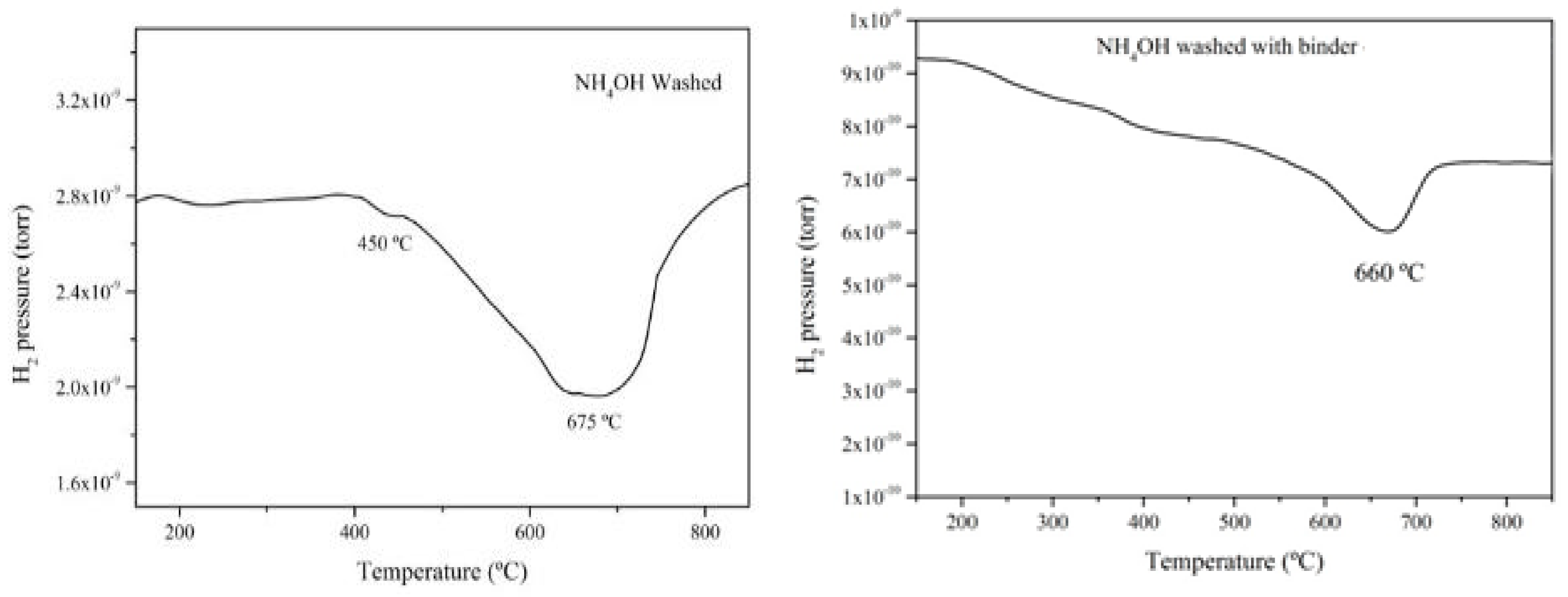
2.9. Temperature Programmed Reduction (TPR)
TPR of the two catalysts are quite similar, with reduction temperature of 675°C for Ni/SBA-15 catalyst and 660°C for Ni/SBA-15 with 36% binder catalyst, respectively. However, the reduction intensity of Ni/SBA-15 catalyst is higher, consuming 29% hydrogen compared with Ni/SBA-15 with 36% binder which consumed 16% of hydrogen during reduction. The reason for the difference in the amount of hydrogen consumed may be due to the slightly lower amount of nickel content in Ni/SBA-15 with 36% binder catalyst (4 wt.%) compared to the original Ni/SBA-15 catalyst (5.7 wt.%)
Figure 6.
TPR of Ni/SBA-15 catalyst (A) and Ni/SBA-15 catalyst with 36% binder (B) respectively.
2.10. Pilot Plant Test Procedure
Biogreen® process patented by ETIA for thermochemical conversion was used for this research study. A catalytic reactor 12 cm in diameter and 30 cm length containing 1kg of the novel Ni/SBA-15 pellets with bed porosity of approximately 0.4 was fitted to the pyrolysis reactor, so that the exiting raw hot vapour stream first passes through the catalytic reactor before analysis as illustrated in Figure 7.
Continuous pyrolysis of dried sewage sludge was carried out at constant residence time of 20 minutes regulated by screw rotation speed setting for each set of the experiment. The pyrolysis reactor temperature was maintained at 800°C by its low voltage electrically heated screw conveyor, because of the Joule effect. The solid residue from pyrolysis was cooled in a double jacket cooler and collected in a separate container as shown in Figure 7. The raw vapour, either with or without the catalytic reactor, was passed through a condenser and any condensed liquid fraction was collected in a separate container. A summary of the operating conditions used for pyrolysis of dried sewage sludge is shown in Table 3:
2.11. Analysis of Liquid and Gas Pyrolysis Fractions
The water content in the pyrolysis liquid fraction was determined using fractional distillation. Nitrogen and sulphur content in the liquid fraction was analysed with Antek 9000 Nitrogen/Sulphur Analyser. Organic compounds in tar were analysed offline with gas chromatography mass spectrometry (GC-MS). Non-condensable gases were analysed online with a gas chromatogram (Not shown in Figure 7) and the rest of the gas burnt safely in a combustion chamber.
2.12. Catalyst Characterisation
Fresh and used Ni/SBA-15 catalyst pellets were characterised with Hitachi S-3400N variable pressure Scanning Electron Microscopy (SEM) to study any changes in the morphology of the catalysts after reaction. Energy Dispersive X-ray (EDX) was carried out for elemental analysis of spent catalyst. JEOL 2100F FEG Transmission Electron Microscope (TEM) with Schottky field emitter operated at 200 kV and catalyst samples ultra-sonicated and dispersed onto holey carbon grids in TEM mode was used to study the dispersion and possible aggregation of nickel particles on the SBA-15 support in Ni/SBA-15 catalyst before and after reaction. Thermal gravimetric analysis (TGA) of spent catalyst was done to determine carbon content by percentage weight loss in oxidative atmosphere from 24–1000°C at 10°/min ramp rate with 15mg of spent catalyst.
3. Pilot Plant Test Results and Discussion
Pyrolysis of dried sewage sludge was carried out without and with the catalytic reactor containing 1kg of Ni/SBA-15 catalyst pellets. The cooled liquid and solid fraction yields were collected and weighed, while the gas fraction was calculated by mass balance. Pyrolysis without catalytic reactor is labelled as Test 1, while the test run with the catalytic reactor is labelled Test 2. The product yield in Figure 8 show that the chosen pyrolysis operating conditions favoured more gas production as desired, however the formation of the liquid and solid fractions are inevitable. Introduction of the catalytic unit had significant effect on the product yield as gas fraction increased from 52.7 to 58.4 %. The increase in gas fraction is due to tar catalytic cracking to non-condensable gas, causing the liquid fraction to drop from 11.7 to 6.4 %. The use of catalyst did not change the solid fraction yield since only the volatile products were passed through the catalytic reactor. The solid fractions for Tests 1 and 2 were collected separately before catalytic cracking. A summary of the percentage product yield for Test 1 and Test 2 is shown in Figure 8:
3.1. Characterisation of Pyrolysis Liquid Fraction Without Catalytic Cracking
The liquid fraction from pyrolysis of sewage sludge without the catalytic reactor was analysed to understand the composition. Analysis in Table 2 show that not all of the liquid fraction is tar. Instead, 55 % of the liquid is water which may have come from both condensation reactions during pyrolysis and some moisture in the sludge which had 7.8 % moisture content. It therefore means that the remaining 45 % by mass balance is considered tar. Pyrolysis liquid contains 4803 µg/ml and 704 µg/ml nitrogen and sulphur respectively. Sulphur is known to deactivate most of the reported catalysts, and so, only sulphur tolerant catalysts, such as the novel Ni/SBA-15 catalyst, can remain catalytically active in tar cracking at this high sulphur content.
A summary of the liquid analysis is shown in Table 4.
The pyrolysis liquid fraction was analysed in GC-MS and the composition of the organic compounds quantified as shown in Table 5. Tar from pyrolysis of sewage sludge contains a mixture of different organic compounds. Polycyclic aromatic hydrocarbons (PAHs) were not detected which suggests that pyrolysis at 800°C was sufficient to decompose PAHs in the liquid fraction, leaving only lighter aromatics, aliphatic, phenols etc. In addition to light aromatics excluding benzene, the tar sample has high pyridine content (20.2 %) and lower acids content (9.1 %), which explains why the pyrolysis liquid fraction is basic with a pH of 9, also considering the fact that 55 % of the liquid fraction is water which mostly resulted from the many condensation reactions that occurred during pyrolysis.
3.2. Pyrolysis Gas Composition
The composition of the non-condensable gas fractions before and after the introduction of the catalytic reactor is shown in Figure 9. The Ni/SBA-15 catalyst had significant effect on the gas composition as H2 increased from 22.24 % to 28.11 %, CO increased from 25.99 % to 30.59 %, CO2 an inert gas, decreased from 12.25 % to 10.27 % due to the fact that some dry (CO2) reforming of methane took place alongside catalytic tar cracking with the Ni/SBA-15 catalyst. Some of the non-condensable hydrocarbons were cracked to smaller fractions as they decreased slightly from 2.88 % to 2.76 %. The calorific value of the pyrolysis gas increased from 16.56 MJ/m3 without catalytic reactor to 18.74 MJ/m3 with the catalytic reactor due to the increase in H2, CO, CH4 and CnHm and a decrease in CO2 contents arising from catalytic tar cracking.
Since pyrolysis liquid decreased from 11.7 % to 6.4 %, which corresponds to 45 % decrease in the liquid fraction (Figure 8), and the pyrolysis liquid constitutes 55 % water and 45 % tar (Table 4), it is therefore plausible to say that 100 % of the tar present in the liquid fraction was converted to non-condensable gases by catalytic cracking with the novel Ni/SBA-15 catalyst pellets.
3.3. Characterisation of the Catalyst Before and After Reaction
The catalytic reactor recorded 100 % tar cracking to gas fraction using the novel Ni/SBA-15 catalyst pellet bed. The catalyst before and after reaction was compared to see if any significant or detrimental changes occurred in the catalyst from sintering or carbon deposition, the two major reasons commercial catalysts get deactivated in hot gas clean-up systems aimed at eliminating tar from the vapour stream.
3.3.1. SEM and TEM Results
SEM images of the fresh and used catalyst appear the same, the reaction conditions did not destroy the morphology of the catalyst. Comparing the TEM images C and D of the catalysts, nickel particles were highly dispersed on the SBA-15 catalyst support of the Ni/SBA-15 catalyst. No major nickel aggregation was observed before or after the reaction, an indication that no significant nickel sintering and agglomeration occurred during the course of the reaction.
3.3.2. Thermogravimetric Analysis (TGA)
The major hindrance to the commercialisation of nickel-based catalyst for tar cracking is that they are easily prone to carbon deposition which results in catalyst deactivation over a short period of time. TGA of spent catalyst (Figure 11) from Test 2 revealed that only a small amount of carbon deposition (1.27 %) was present on the spent catalyst. DSC temperature for oxidation of the carbon species occurred at 390°C, an indication that the carbon type is amorphous which is easily oxidised during the reaction [46]. Since the catalyst remained highly active throughout the duration of the experiment, we can conclude that the small carbon deposition did not inhibit catalytic performance as the ultrafine nickel particles were active enough to prevent any major carbon build-up.
4. Comparing the Catalytic Performance of Crushed Ni-SBA-15 Pellets with the Powered Ni-SBA-15 Catalyst Without Binder
At lab scale, Hiden Analytical CATLAB micro-reactor system was used to compare the catalytic performance of Ni-SBA-15 catalysts with and without the binder. This is to better understand the effect of adding the binder recipe to the catalyst beyond the reported physical properties. Dry Methane Reforming was selected as a reaction test since this also occur during catalytic tar cracking and nickel-based catalysts are also prone to carbon deposition in DRM.
4.1. Catalytic Test Evaluation
Catalytic activity tests were carried out with Hiden Analytical CATLAB—quadrupole mass spectrometer micro-reactor system (fixed bed quartz tube 4mm i.d and 18.5 cm in length) in continuous flow. Hydrogen temperature programmed reduction was done by flowing 5% H2 in Ar at flow rate of 30ml/min, with the reactor heated from room temperature to 850 °C at 20°/min ramp rate. The catalytic activity of hydrogen reduced catalysts were carried out at GHSV of 888 h-1 for CH4/CO2 reactant ratio of 2.7. The amount of carbon deposition on the spent catalysts after reaction was measured by thermal gravimetric analysis (TGA) of Thorn Scientific Services in oxidative atmosphere with heating temperature raised from room temperature to 1000 °C at 10 °/min ramp rate.
4.2. Temperature Programmed Reaction (TPRx)
CH4/CO2 reactant ratio of 2.7 was used to test and compare the catalytic activity of the original Ni/SBA-15 and that with 36% colloidal silica binder. The difference in catalytic performance is seen in Figure 12. For Ni/SBA-15 catalyst with binder, initial reaction temperature starts at 380°C, unlike the pure Ni/SBA-15 catalyst at 280 °C. It is possible that the original Ni/SBA-15 catalyst was more active at lower temperature due to the presence of smaller sized nickel particles which proved to be more active than the 7nm sized nickel particles for the Ni/SBA-15 catalyst with binder at lower reaction temperature. At higher reaction temperatures of 560–850°C, Ni/SBA-15 catalyst with binder attained 97% CO2 conversion and remained stable up to 850°C optimum test temperature. The original Ni/SBA-15 catalyst also had high CO2 conversion which however fluctuated between 92 and 97%. The reason for the higher catalytic stability of the Ni/SBA-15 catalyst with 36% colloidal silica binder may be that the binder acted as a shield which restricted the mobility, agglomeration and sintering of nickel particles outside the pores of the catalyst, thereby improving significantly, the catalyst activity and stability in high reaction temperatures.
4.3. Catalyst Life-Time-Test-On Stream
The two catalysts proved to be highly active and stable throughout the 72 hours’ test period producing H2 and CO only. TEM images of the spent catalysts shown in Figure 13 reveal no major agglomeration of nickel particles after reaction, and the pore channels of the catalysts were not destroyed, a further confirmation that the catalysts are highly stable in high temperature DRM reactions.
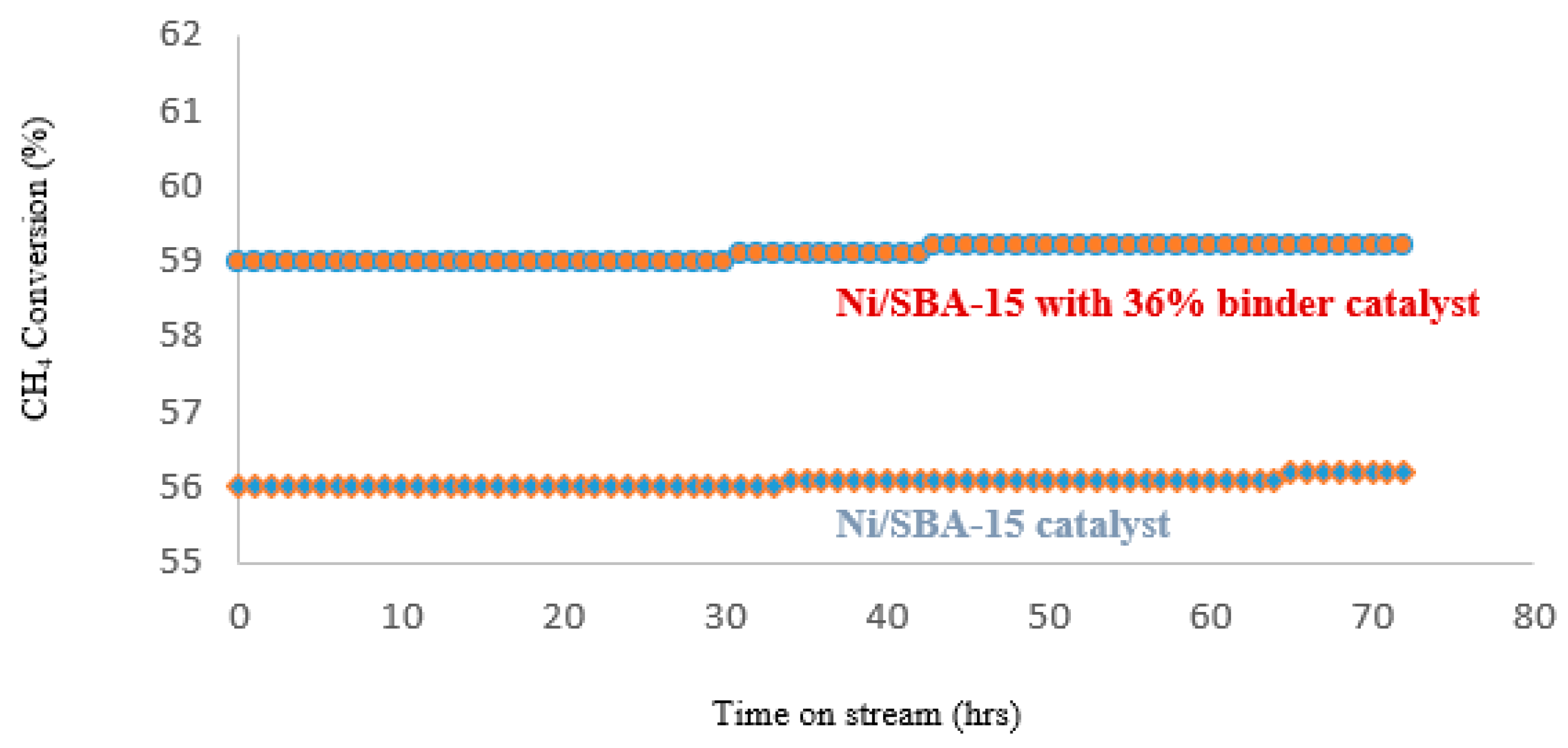
Ni/SBA-15 catalyst maintained 87–88% CO2 conversion, while Ni/SBA-15 catalyst with binder had higher CO2 conversion of 97%. With methane conversion, Ni/SBA-15 catalyst with 36% colloidal silica binder was stable at 59 %, while Ni/SBA-15 catalyst at 56 %. It therefore means that the addition of colloidal silica binder did not in any way inhibit catalytic activity of the Ni/SBA-15 catalyst, rather, it seems to have resisted the mobility of some of the nickel particles on the external surface, that is, outside of the catalyst pores, thereby reducing agglomeration and sintering of some nickel particles which consequently increased catalytic activity of Ni/SBA-15 catalyst with 36% colloidal silica binder at high reaction temperature range.
Figure 15.
CH4 conversion of the two catalysts in DRM at 70 °C for 72 hours.
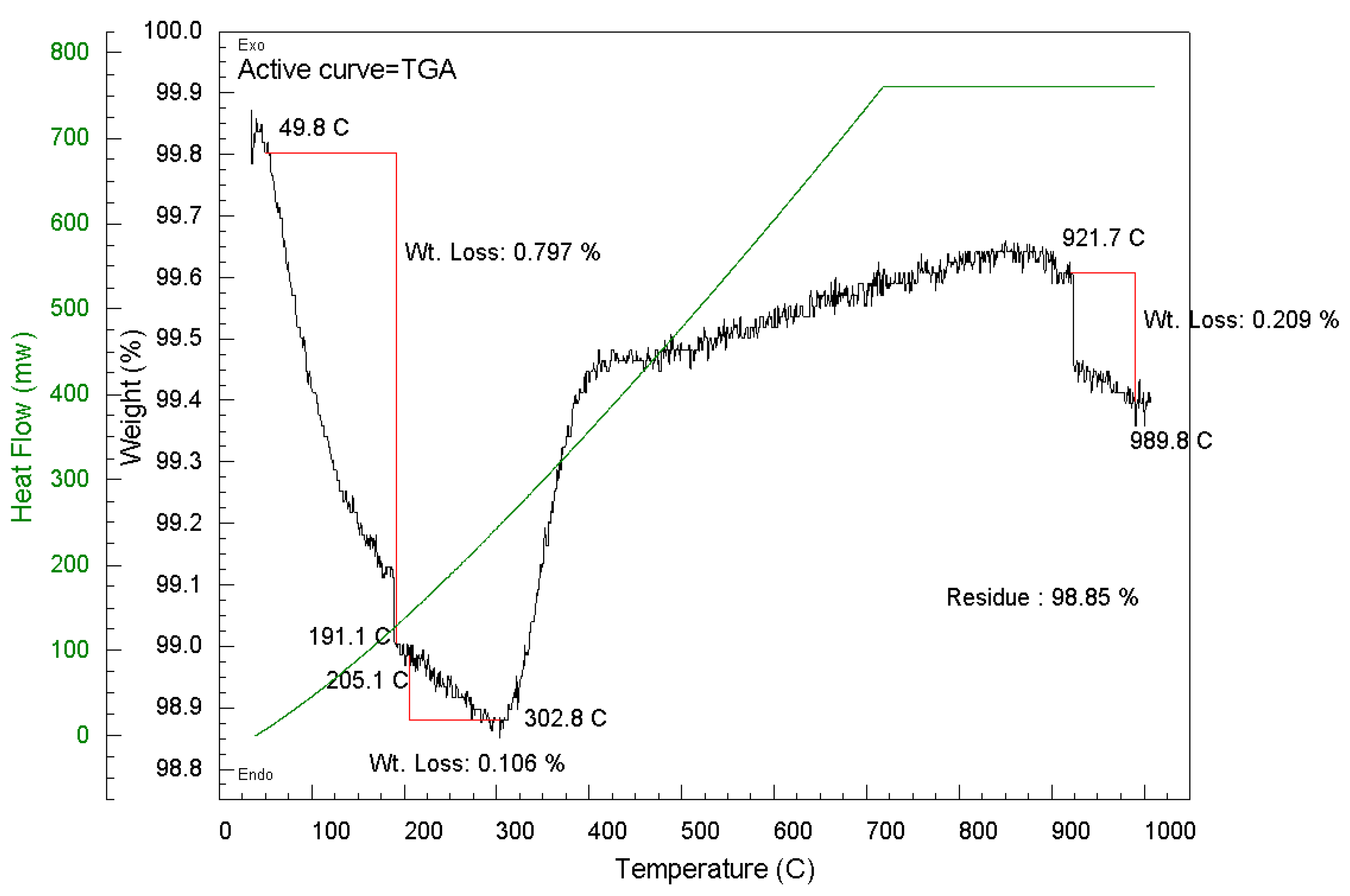
4.4. Thermogravimetric Analysis (TGA)
The percentage weight loss from TGA results of both catalysts which corresponds to the amount of carbon lost via oxidation in air are shown in Figure 12 and Figure 13. Weight losses within 160°C is attributed to loss of adsorbed moisture on the catalysts. Both catalysts recorded only small amount of carbon deposition. However, Ni/SBA-15 with 36% binder catalyst had the lowest carbon deposition of 0.32%, while Ni/SBA-15 catalyst had 1.43 % after 72 hours’ time on stream at 700 °C. This further explains why the Ni/SBA-15 catalyst with binder was slightly more active; less nickel sintering occurred on the catalyst with binder during the course of 72-hour time on stream; and so, had a better resistance against carbon deposition. However, the amount of carbon formed on both catalysts were relatively small and did not in any way decrease the activity or stability of the catalysts during the 72-hour time on stream.
Figure 16.
TGA of Ni/SBA-15 catalyst without binder.
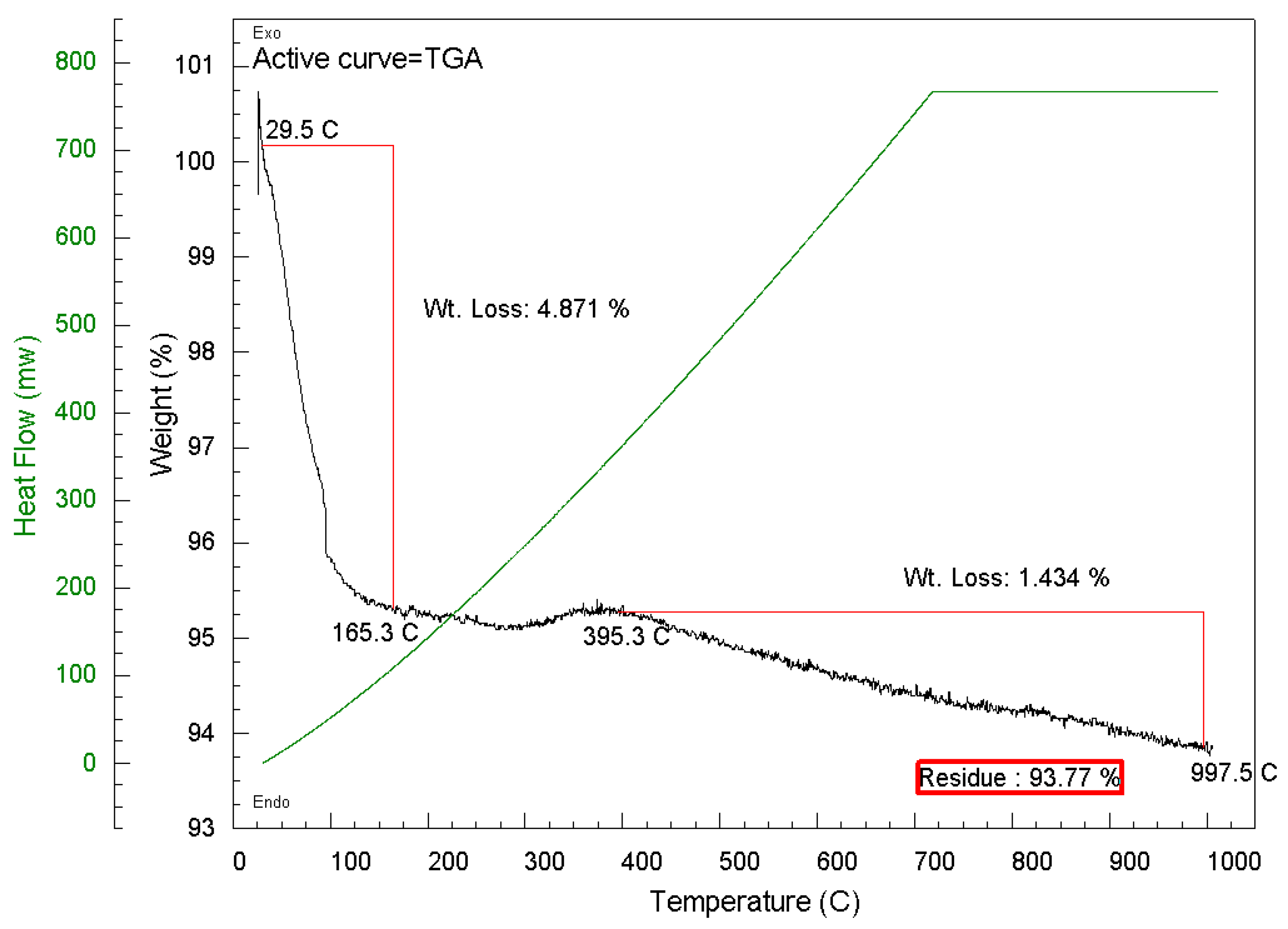
Figure 17.
TGA of Ni/SBA-15 catalyst with binder.
5. Conclusions
The purpose of this contribution was to scale up, shaping into pellets and testing in a pilot plant the newly-developed Ni/SBA-15 catalysts. Pilot plant tests, aimed at converting sewage sludge pyrolysis condensable fraction to non-condensable gas fraction, revealed that the catalyst pellets were able to crack 100% of the tar into smaller hydrogen, carbon monoxide and methane. Dry reforming of carbon dioxide in the gas with hydrocarbons also took place. A combination of CO2 reforming and tar cracking significantly increased the gas fraction, reduced CO2 content and increased the final gas calorific value. Characterisation results showed that the Ni/SBA-15 catalyst pellets remained active and did not sinter nor deactivate from carbon deposition. The ability to shape Ni-SBA-15 catalyst into pellets, using methyl cellulose and colloidal silica as binders, is a major step towards the large-scale commercialisation of catalytic tar cracking of hot vapour derived from biomass pyrolysis into syngas for various applications.
References
- C.o.E. Communities, Council Directive 91/271/EEC of 21 March 1991 concerning urban waste-water treatment (amended by the 98/15/EC of 27 February 1998).
- G. Williams, N. Aitkenhead, Lessons from Loscoe: the uncontrolled migration of landfill gas. Quarterly Journal of Engineering Geology and Hydrogeology 1991, 24, 191–207. [Google Scholar] [CrossRef]
- P. Boeckx, O.v. Cleemput, I. Villaralvo, Methane emission from a landfill and the methane oxidising capacity of its covering soil. Soil Biology and Biochemistry 1996, 28, 1397–1405. [Google Scholar] [CrossRef]
- B. W. Mosher, P.M. Czepiel, R.C. Harriss, J.H. Shorter, C.E. Kolb, J.B. McManus, E. Allwine, B.K. Lamb, Methane Emissions at Nine Landfill Sites in the Northeastern United States. Environmental Science & Technology 1999, 33, 2088–2094. [Google Scholar]
- M. d.A.F. Al-Dabbas, Reduction of methane emissions and utilization of municipal waste for energy in Amman. Renewable Energy 1998, 14, 427–434. [Google Scholar] [CrossRef]
- M. Zamorano, J. Ignacio Pérez Pérez, I. Aguilar Pavés, Á. Ramos Ridao, Study of the energy potential of the biogas produced by an urban waste landfill in Southern Spain. Renewable and Sustainable Energy Reviews 2007, 11, 909–922. [Google Scholar] [CrossRef]
- M. Lundin, M. Olofsson, G.J. Pettersson, H. Zetterlund, Environmental and economic assessment of sewage sludge handling options, Resources. Conservation and Recycling 2004, 41, 255–278. [Google Scholar] [CrossRef]
- S.E. Harakeh, N. S.E. Harakeh, N. Mahmood, Y. Zhang, Sewage Sludge Process Improvement Investigation for London, Ontario in: Green Fuels and Chemicals, University of Western Ontario. Department of Chemical and Biochemical Engineering, 2011.
- G. Maschio, C. Koufopanos, A. Lucchesi, Pyrolysis, a promising route for biomass utilization. Bioresource Technology 1992, 42, 219–231. [Google Scholar] [CrossRef]
- A. V. Bridgwater, The technical and economic feasibility of biomass gasification for power generation. Fuel 1995, 74, 631–653. [Google Scholar] [CrossRef]
- C. Higman, M. C. Higman, M. Van der Burgt, Gasification, Gulf professional publishing, 2011.
- P. McKendry, Energy production from biomass (part 3): gasification technologies. Bioresource Technology 2002, 83, 55–63. [Google Scholar] [CrossRef]
- Z. -b. Hu, W.R.G. Saman, R.R. Navarro, D.-y. Wu, D.-l. Zhang, M. Matsumura, H.-n. Kong, Removal of PCDD/Fs and PCBs from sediment by oxygen free pyrolysis. Journal of Environmental Sciences 2006, 18, 989–994. [Google Scholar] [CrossRef]
- P. Manara, A. Zabaniotou, Towards sewage sludge based biofuels via thermochemical conversion—A review. Renewable and Sustainable Energy Reviews 2012, 16, 2566–2582. [Google Scholar] [CrossRef]
- Fonts, M. Azuara, G. Gea, M.B. Murillo, Study of the pyrolysis liquids obtained from different sewage sludge. Journal of Analytical and Applied Pyrolysis 2009, 85, 184–191. [Google Scholar] [CrossRef]
- Domínguez, Y. Fernández, B. Fidalgo, J.J. Pis, J.A. Menéndez, Bio-syngas production with low concentrations of CO2 and CH4 from microwave-induced pyrolysis of wet and dried sewage sludge. Chemosphere 2008, 70, 397–403. [Google Scholar] [CrossRef] [PubMed]
- T. Karayildirim, J. Yanik, M. Yuksel, H. Bockhorn, Characterisation of products from pyrolysis of waste sludges. Fuel 2006, 85, 1498–1508. [Google Scholar] [CrossRef]
- R. Font, A. Fullana, J.A. Conesa, F. Llavador, Analysis of the pyrolysis and combustion of different sewage sludges by TG. Journal of Analytical and Applied Pyrolysis 2001, 58–59, 927–941. [Google Scholar]
- M. E. Sánchez, O. Martínez, X. Gómez, A. Morán, Pyrolysis of mixtures of sewage sludge and manure: A comparison of the results obtained in the laboratory (semi-pilot) and in a pilot plant. Waste Management 2007, 27, 1328–1334. [Google Scholar] [CrossRef]
- F. Shafizadeh, Introduction to pyrolysis of biomass. Journal of Analytical and Applied Pyrolysis 1982, 3, 283–305. [Google Scholar] [CrossRef]
- M. Inguanzo, A. Domı́nguez, J.A. Menéndez, C.G. Blanco, J.J. Pis, On the pyrolysis of sewage sludge: the influence of pyrolysis conditions on solid, liquid and gas fractions. Journal of Analytical and Applied Pyrolysis 2002, 63, 209–222. [Google Scholar] [CrossRef]
- Bridgwater, Renewable fuels and chemicals by thermal processing of biomass. Chemical Engineering Journal 2003, 91, 87–102. [CrossRef]
- J. Ábrego, J. Arauzo, J.L. Sánchez, A. Gonzalo, T. Cordero, J. Rodríguez-Mirasol, Structural changes of sewage sludge char during fixed-bed pyrolysis. Industrial & Engineering Chemistry Research 2009, 48, 3211–3221. [Google Scholar]
- H. J. Park, H.S. Heo, Y.-K. Park, J.-H. Yim, J.-K. Jeon, J. Park, C. Ryu, S.-S. Kim, Clean bio-oil production from fast pyrolysis of sewage sludge: Effects of reaction conditions and metal oxide catalysts. Bioresource Technology 2010, 101, S83–S85. [Google Scholar] [CrossRef]
- J. Piskorz, D.S. Scott, I.B. Westerberg, Flash pyrolysis of sewage sludge. Industrial & Engineering Chemistry Process Design and Development 1986, 25, 265–270. [Google Scholar]
- F. d.M. Mercader, M.J. Groeneveld, S.R.A. Kersten, R.H. Venderbosch, J.A. Hogendoorn, Pyrolysis oil upgrading by high pressure thermal treatment. Fuel 2010, 89, 2829–2837. [Google Scholar] [CrossRef]
- R. K. Sharma, N.N. Bakhshi, Catalytic upgrading of pyrolysis oil. Energy & Fuels 1993, 7, 306–314. [Google Scholar]
- V. A. Doshi, H.B. Vuthaluru, T. Bastow, Investigations into the control of odour and viscosity of biomass oil derived from pyrolysis of sewage sludge. Fuel Processing Technology 2005, 86, 885–897. [Google Scholar] [CrossRef]
- A.V. Bridgwater, G. A.V. Bridgwater, G. Grassi, Biomass pyrolysis liquids upgrading and utilization, Springer Science & Business Media, 2012.
- S. Xiu, A. Shahbazi, Bio-oil production and upgrading research: A review. Renewable and Sustainable Energy Reviews 2012, 16, 4406–4414. [Google Scholar] [CrossRef]
- P. Hasler, T. Nussbaumer, Gas cleaning for IC engine applications from fixed bed biomass gasification. Biomass and Bioenergy 1999, 16, 385–395. [Google Scholar] [CrossRef]
- C. Stevens, R.C. C. Stevens, R.C. Brown, Thermochemical processing of biomass: conversion into fuels, chemicals and power, John Wiley & Sons, 2011.
- C. Xu, J. Donald, E. Byambajav, Y. Ohtsuka, Recent advances in catalysts for hot-gas removal of tar and NH3 from biomass gasification. Fuel 2010, 89, 1784–1795. [Google Scholar] [CrossRef]
- D. J.M.-W. Roddy, Biomass Gasification and Pyrolysis. Comprehensive Renewable Energy 2012, 5, 133–153. [Google Scholar]
- Y. Cao, Y. Wang, J.T. Riley, W.P. Pan, A novel biomass air gasification process for producing tar-free higher heating value fuel gas. Fuel Processing Technology 2006, 87, 343–353. [Google Scholar] [CrossRef]
- I. -S. Antonopoulos, A. Karagiannidis, L. Elefsiniotis, G. Perkoulidis, A. Gkouletsos, Development of an innovative 3-stage steady-bed gasifier for municipal solid waste and biomass. Fuel Processing Technology 2011, 92, 2389–2396. [Google Scholar] [CrossRef]
- S. Zhang, M. Asadullah, L. Dong, H.-L. Tay, C.-Z. Li, An advanced biomass gasification technology with integrated catalytic hot gas cleaning. Part II: Tar reforming using char as a catalyst or as a catalyst support. Fuel 2013, 112, 646–653. [Google Scholar] [CrossRef]
- B. Dou, J. Gao, X. Sha, S.W. Baek, Catalytic cracking of tar component from high-temperature fuel gas. Applied Thermal Engineering 2003, 23, 2229–2239. [Google Scholar] [CrossRef]
- J. Delgado, M.P. Aznar, J. Corella, Calcined Dolomite, Magnesite, and Calcite for Cleaning Hot Gas from a Fluidized Bed Biomass Gasifier with Steam: Life and Usefulness. Industrial & Engineering Chemistry Research 1996, 35, 3637–3643. [Google Scholar]
- S. Anis, Z. Zainal, Tar reduction in biomass producer gas via mechanical, catalytic and thermal methods: A review. Renewable and Sustainable Energy Reviews 2011, 15, 2355–2377. [Google Scholar] [CrossRef]
- T. Wang, J. Chang, P. Lv, J. Zhu, Novel catalyst for cracking of biomass tar. Energy & fuels 2005, 19, 22–27. [Google Scholar]
- L. Devi, K.J. Ptasinski, F.J.J.G. Janssen, A review of the primary measures for tar elimination in biomass gasification processes. Biomass and Bioenergy 2003, 24, 125–140. [Google Scholar] [CrossRef]
- W. Tang. J-P. Cao, Z-M. He, W. Jiang, Z-H. Wang, Recent progress of catalysts for reforming of biomass tar/tar models at low temperature - A short review. ChemCatChem 2023, 15, e202300581. [Google Scholar] [CrossRef]
- S. Mitchell, N-L. Michels, J. Pérez-Ramírez, From powder to technical body: the undervalued science of catalysy scale up. Chem. Soc. Rev. 2013, 42, 6094–6112. [Google Scholar] [CrossRef]
- Iro, E.; Ariga-Miwa, H.; Sasaki, T.; Asakura, K.; Olea, M. Elimination of Indoor Volatile Organic Compounds on Au/SBA-15 Catalysts: Insights into the Nature, Size, and Dispersion of the Active Sites and Reaction Mechanism. Catalysts 2022, 12, 1365. [Google Scholar] [CrossRef]
- D. Liu, X.-Y. Quek, H.H.A. Wah, G. Zeng, Y. Li, Y. Yang, Carbon dioxide reforming of methane over nickel-grafted SBA-15 and MCM-41 catalysts. Catalysis Today 2009, 148, 243–250. [Google Scholar] [CrossRef]
Figure 1.
Preparation of Ni/SBA-15 catalyst pellets.
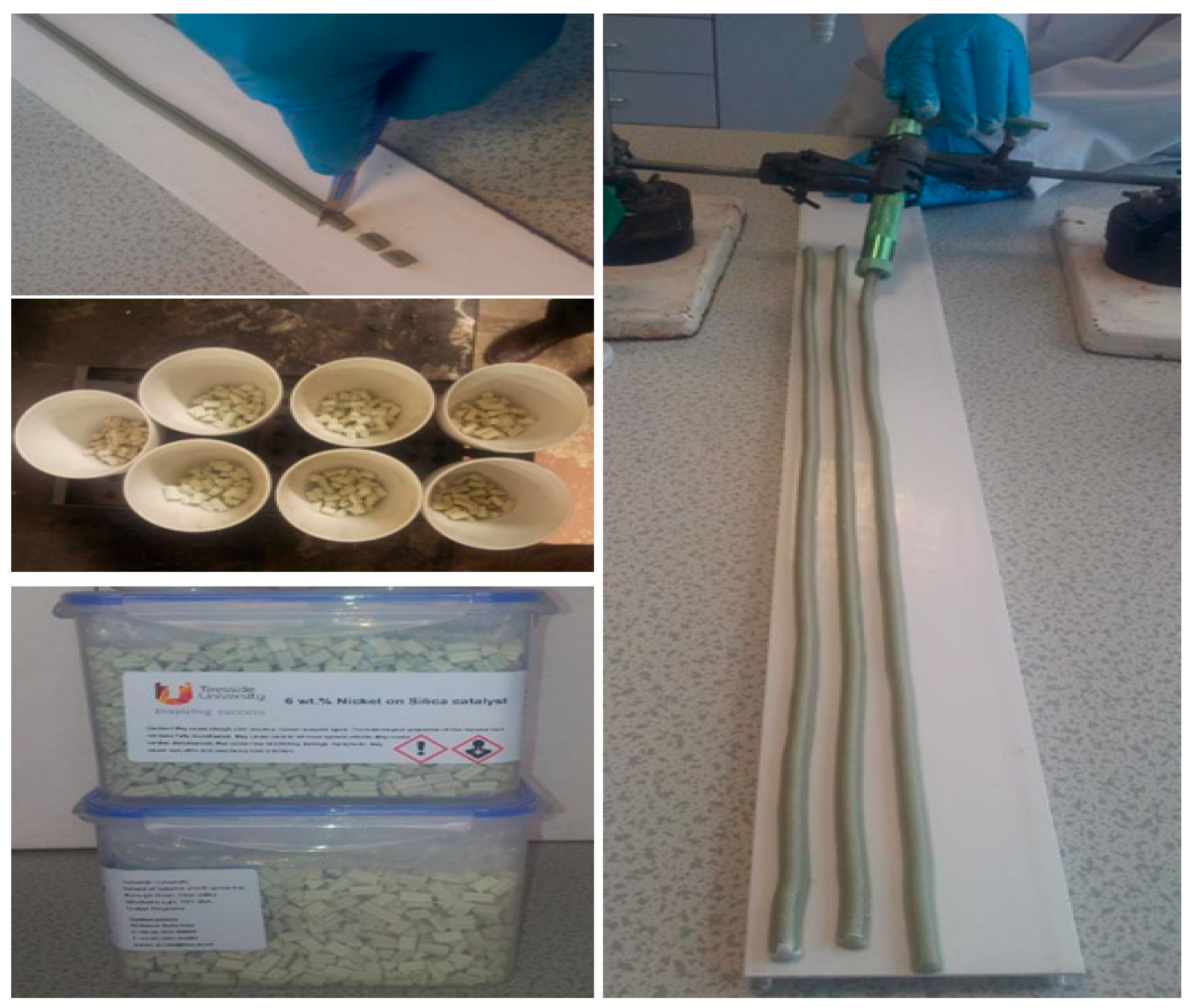
Figure 2.
Mechanical strength of Ni/SBA-15 pellets with different amount of colloidal silica binder.
Figure 2.
Mechanical strength of Ni/SBA-15 pellets with different amount of colloidal silica binder.
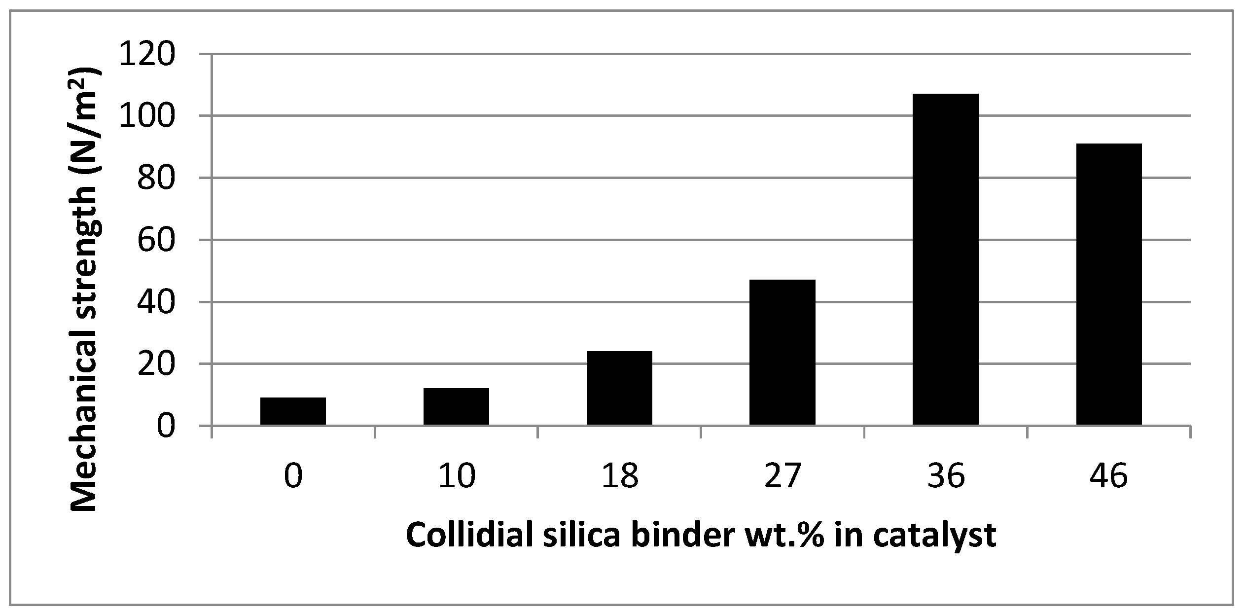
Figure 3.
SEM images of Ni/SBA-15 catalyst (A) and Ni/SBA-15 catalyst with 36% binder (B).
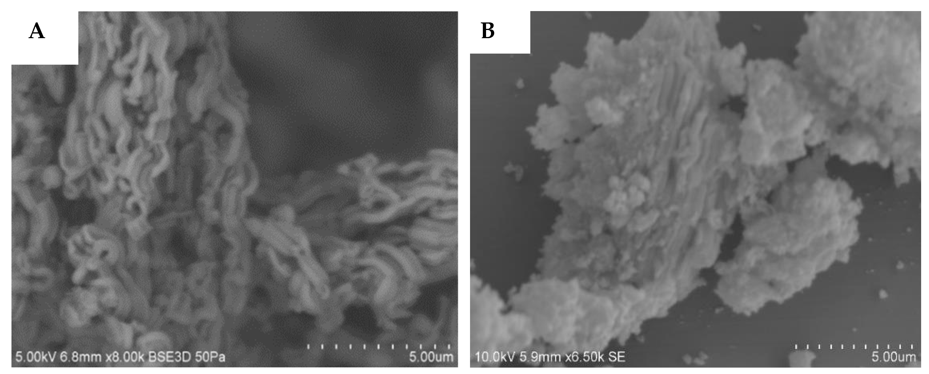
Figure 4.
TEM images of fresh Ni/SBA-15 catalyst (A), and fresh Ni/SBA-15 catalyst with 36% binder (B).
Figure 4.
TEM images of fresh Ni/SBA-15 catalyst (A), and fresh Ni/SBA-15 catalyst with 36% binder (B).
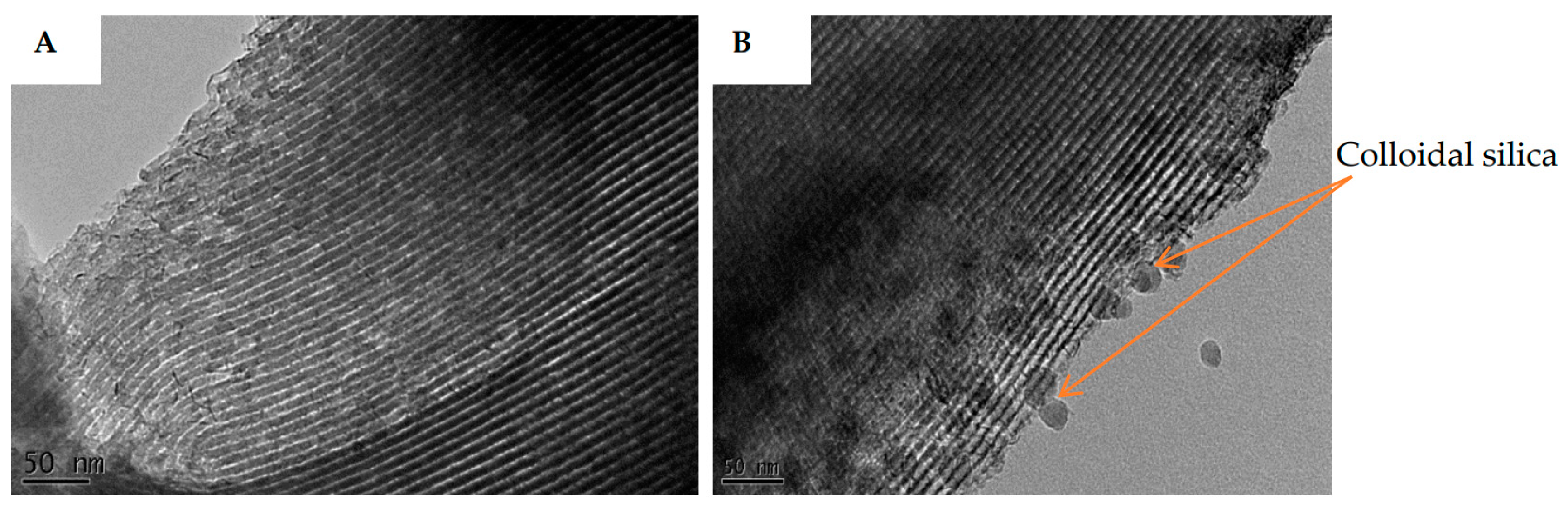
Figure 5.
Wide angle XRD of nickel oxide from calcined nickel acetate tetra hydrate salt at 550 °C.
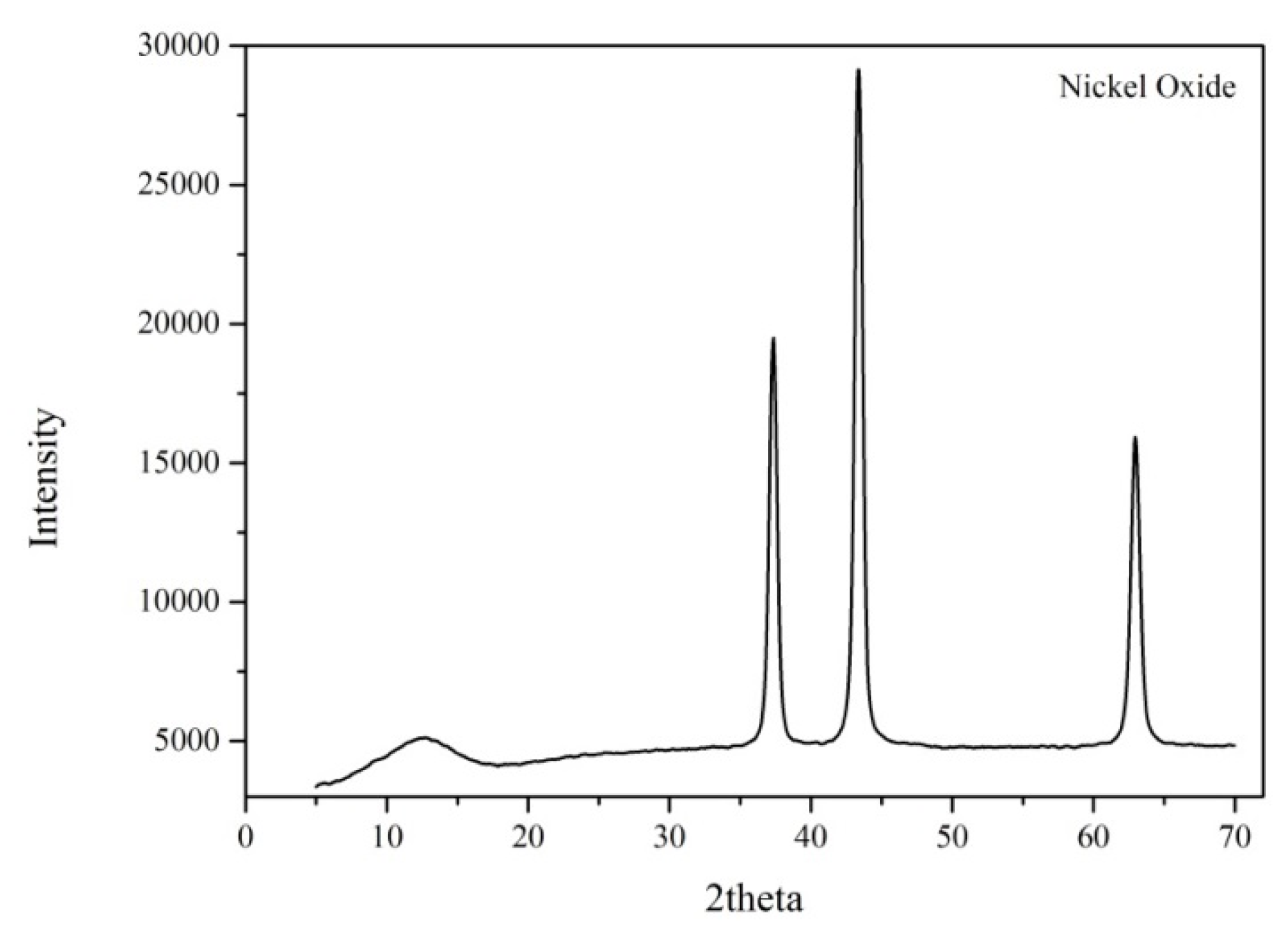
Figure 6.
Wide angle XRD of Ni/SBA-15 catalyst and Ni/SBA-15 catalyst with 36% binder, respectively.
Figure 6.
Wide angle XRD of Ni/SBA-15 catalyst and Ni/SBA-15 catalyst with 36% binder, respectively.
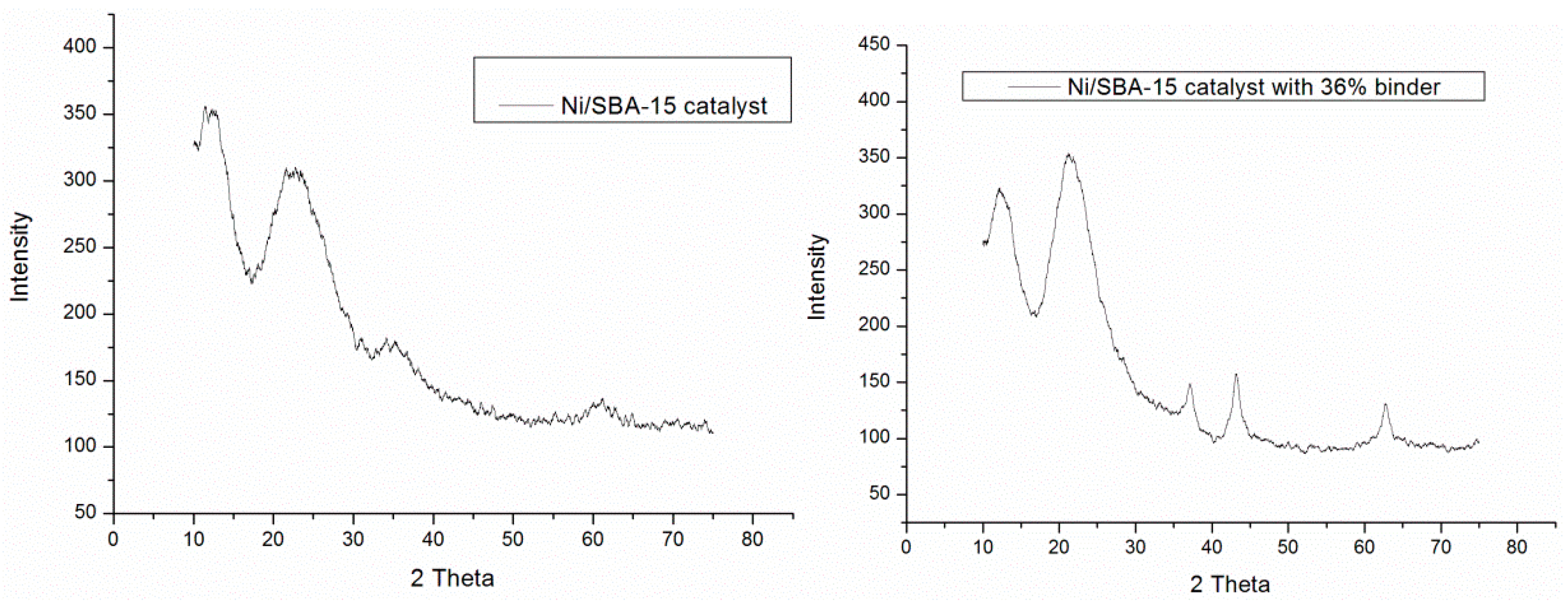
Figure 7.
Spirajoule® pyrolysis process (Biogreen® at ETIA).
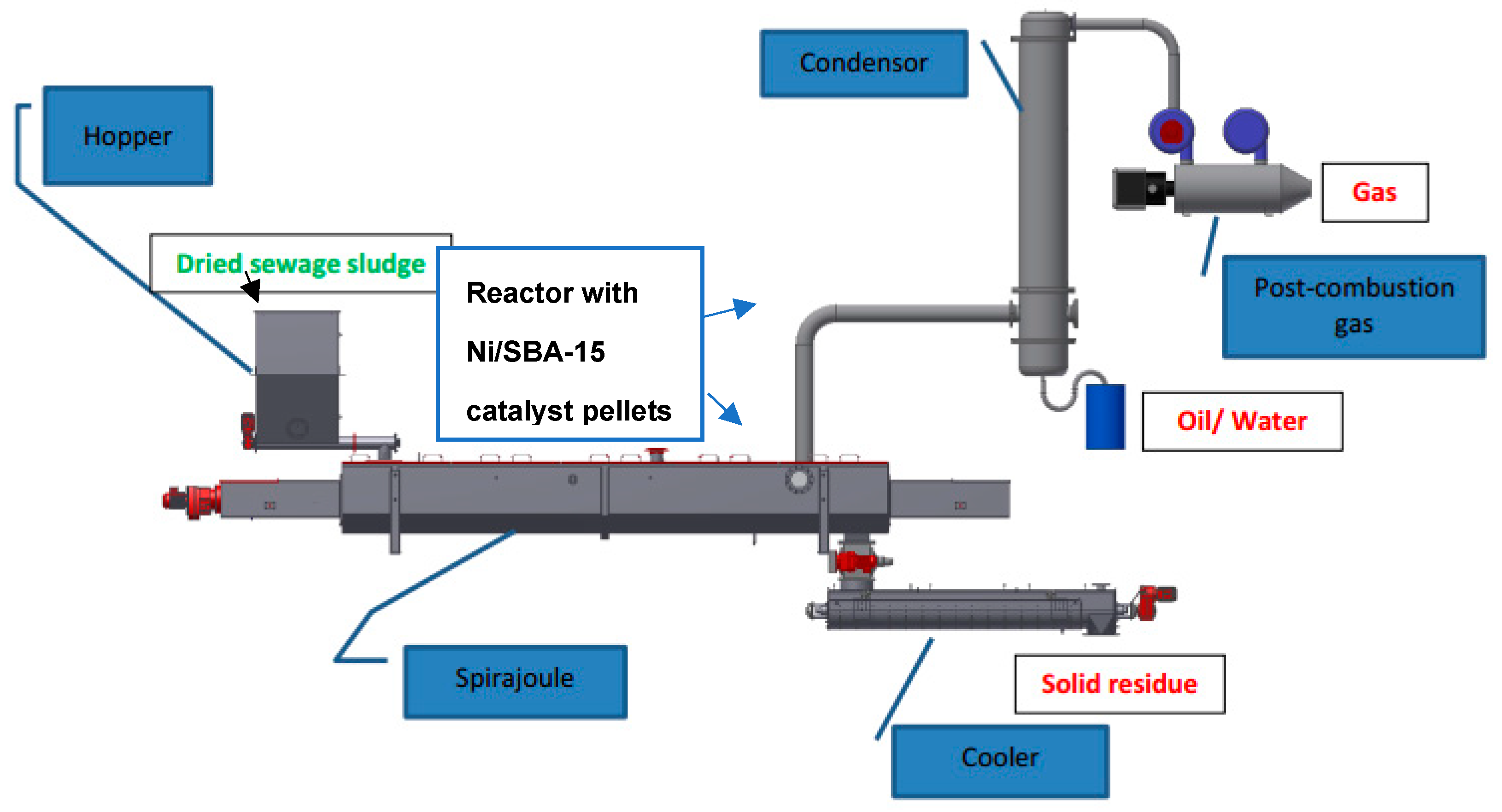
Figure 8.
Pyrolysis of sewage sludge yields with and without the catalytic reactor.
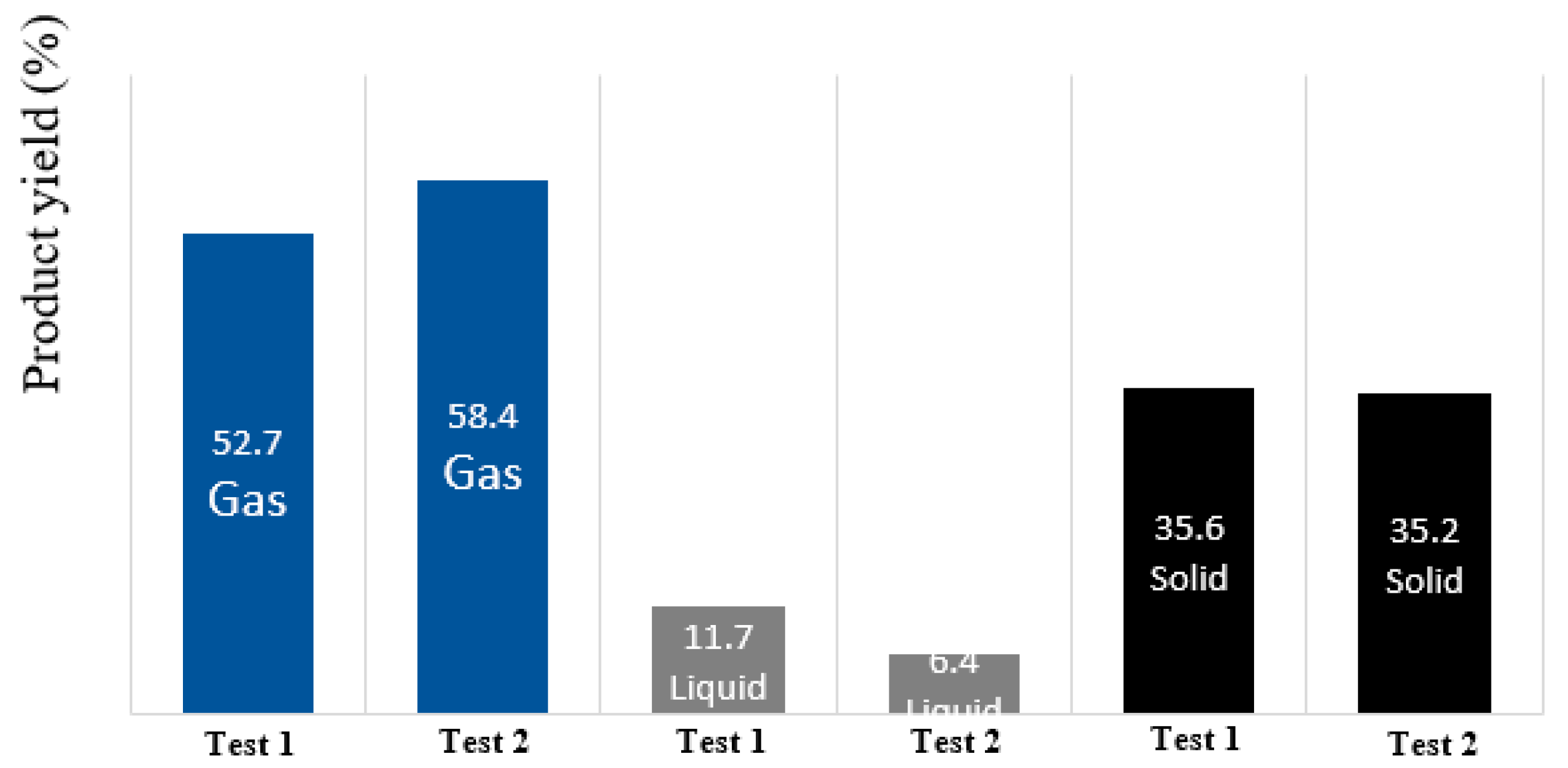
Figure 9.
Pyrolysis gas composition and calorific value before and after catalytic cracking with Ni/SBA-15 catalyst reactor.
Figure 9.
Pyrolysis gas composition and calorific value before and after catalytic cracking with Ni/SBA-15 catalyst reactor.
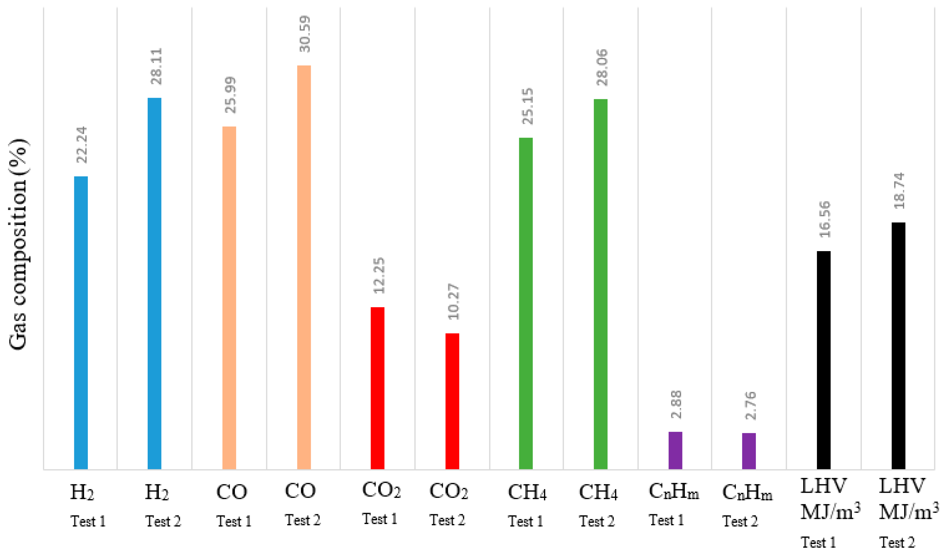
Figure 10.
SEM image of fresh (A) and used (B) Ni/SBA-15 catalyst pellets. TEM image of fresh (C) and used (D) Ni/SBA-15 catalyst pellets.
Figure 10.
SEM image of fresh (A) and used (B) Ni/SBA-15 catalyst pellets. TEM image of fresh (C) and used (D) Ni/SBA-15 catalyst pellets.
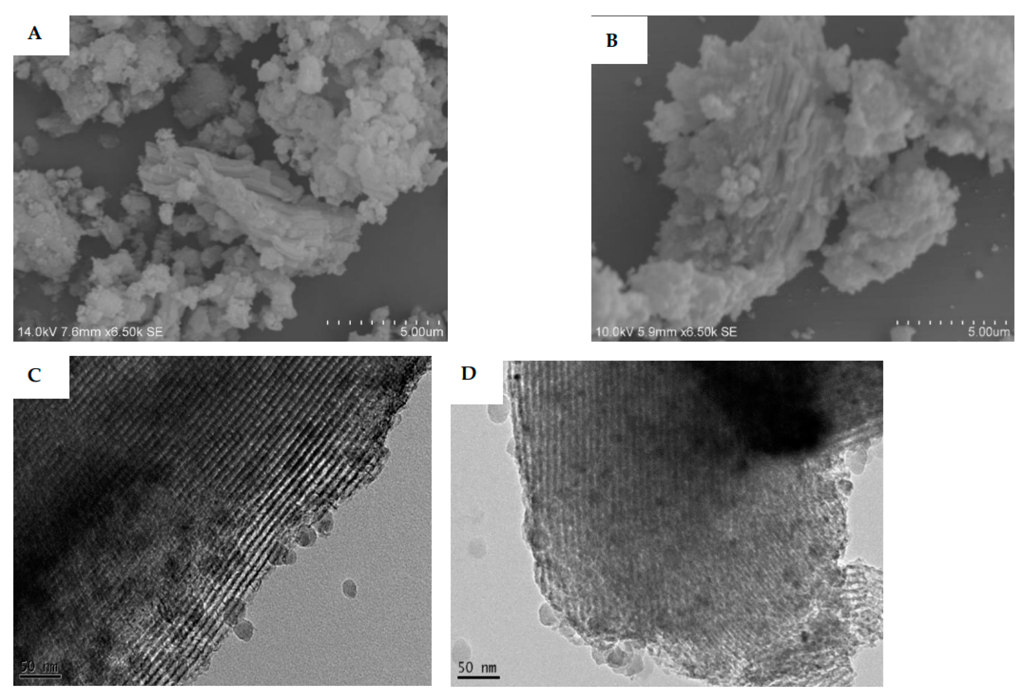
Figure 11.
TGA/DSC of spent Ni/SBA-15 catalyst after pyrolysis.
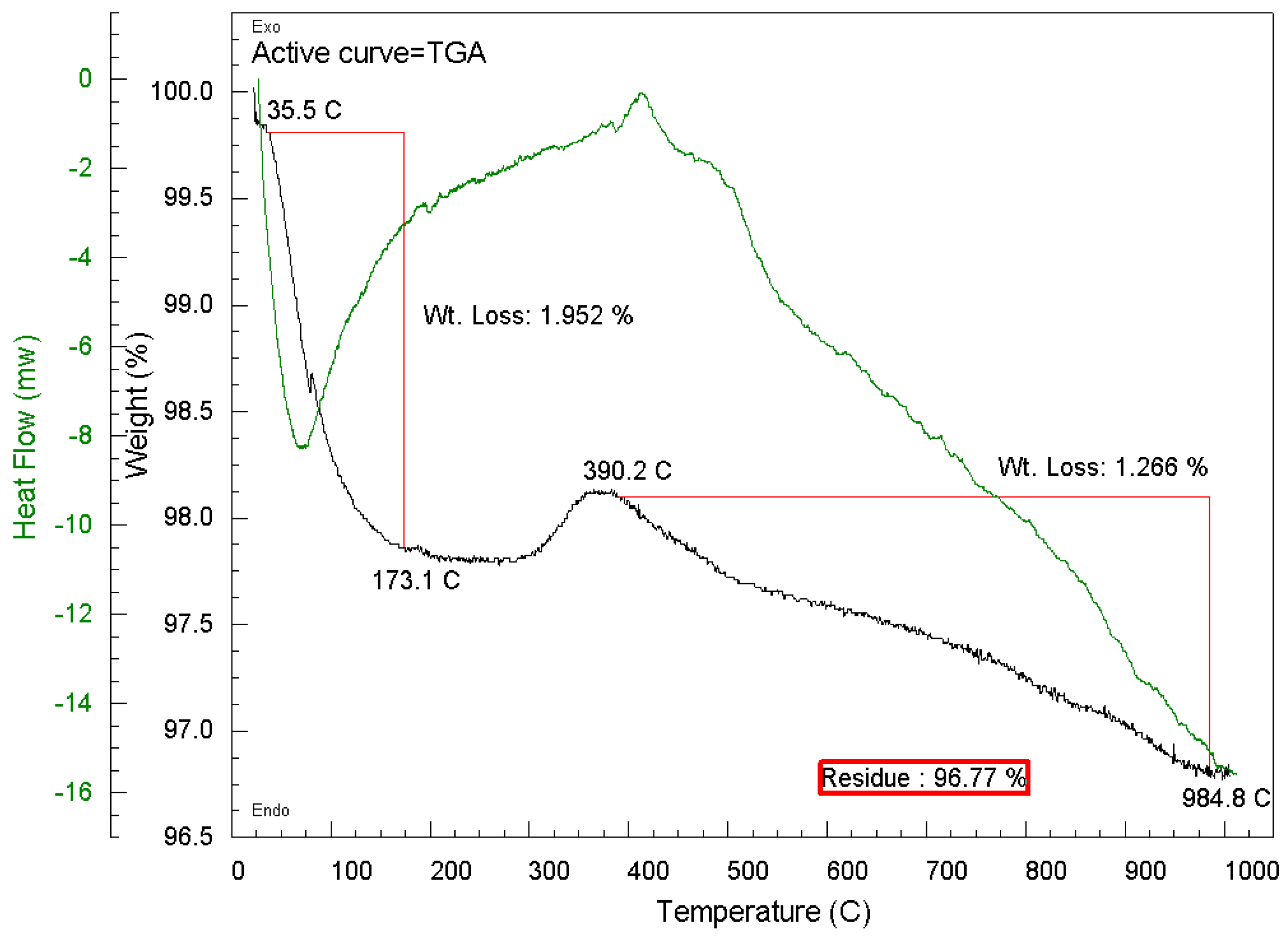
Figure 12.
CO2 conversions of Ni/SBA-15 catalyst and Ni/SBA-15 catalyst with 36% binder in DRM.
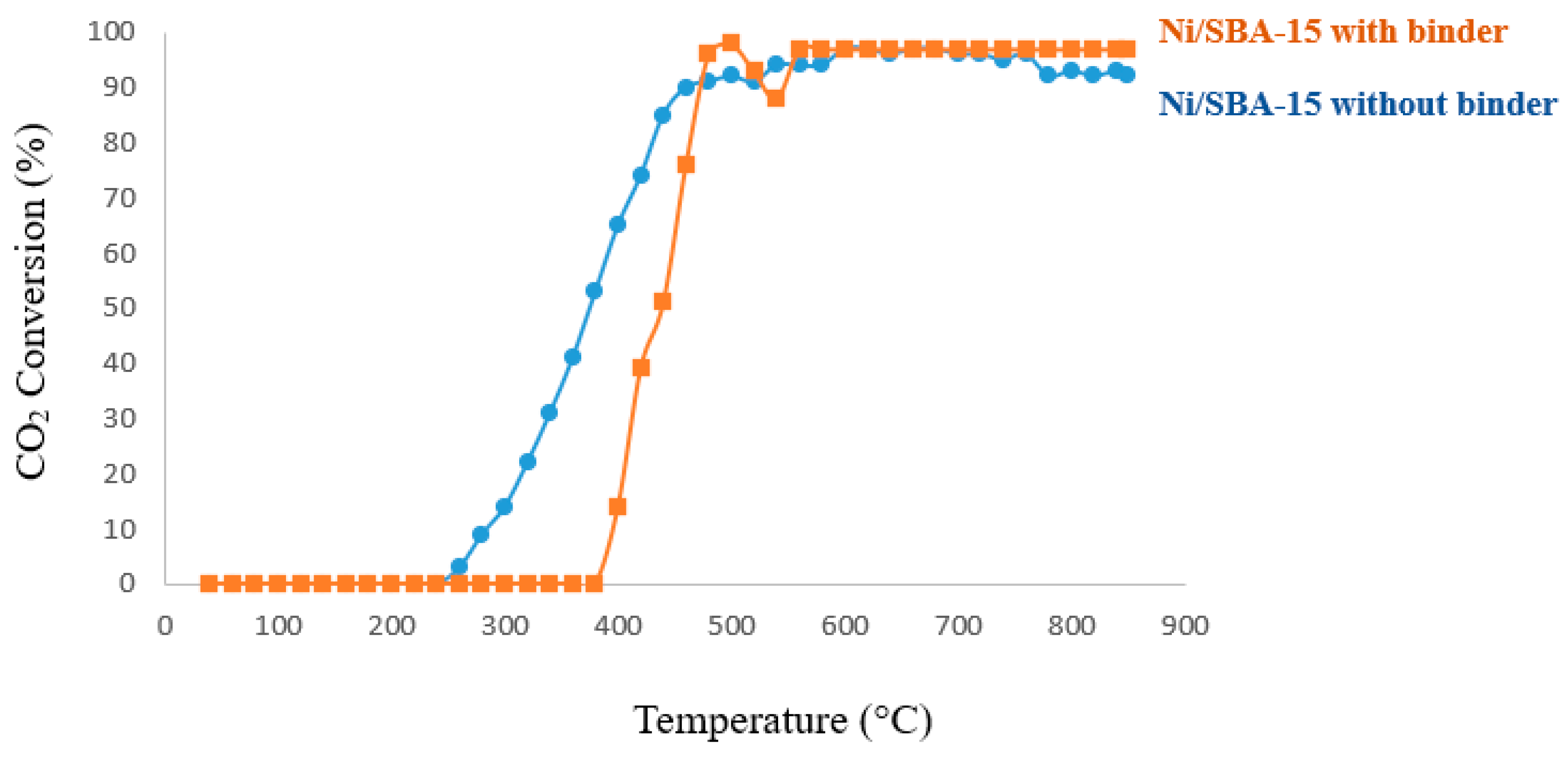
Figure 13.
TEM images spent Ni/SBA-15 catalyst without binder (A) and with 36% binder (B) after 72 hours’ time on stream.
Figure 13.
TEM images spent Ni/SBA-15 catalyst without binder (A) and with 36% binder (B) after 72 hours’ time on stream.
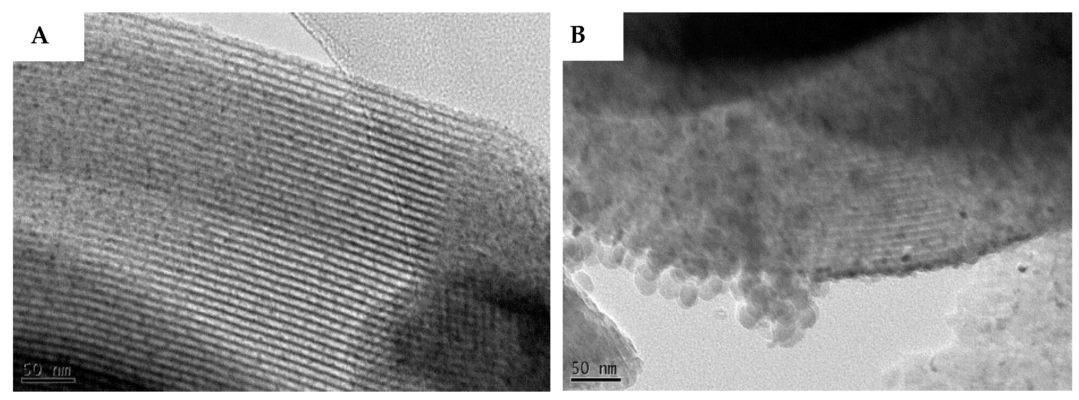
Figure 14.
CO2 conversion of the two catalysts in DRM at 700°C for 72 hours.
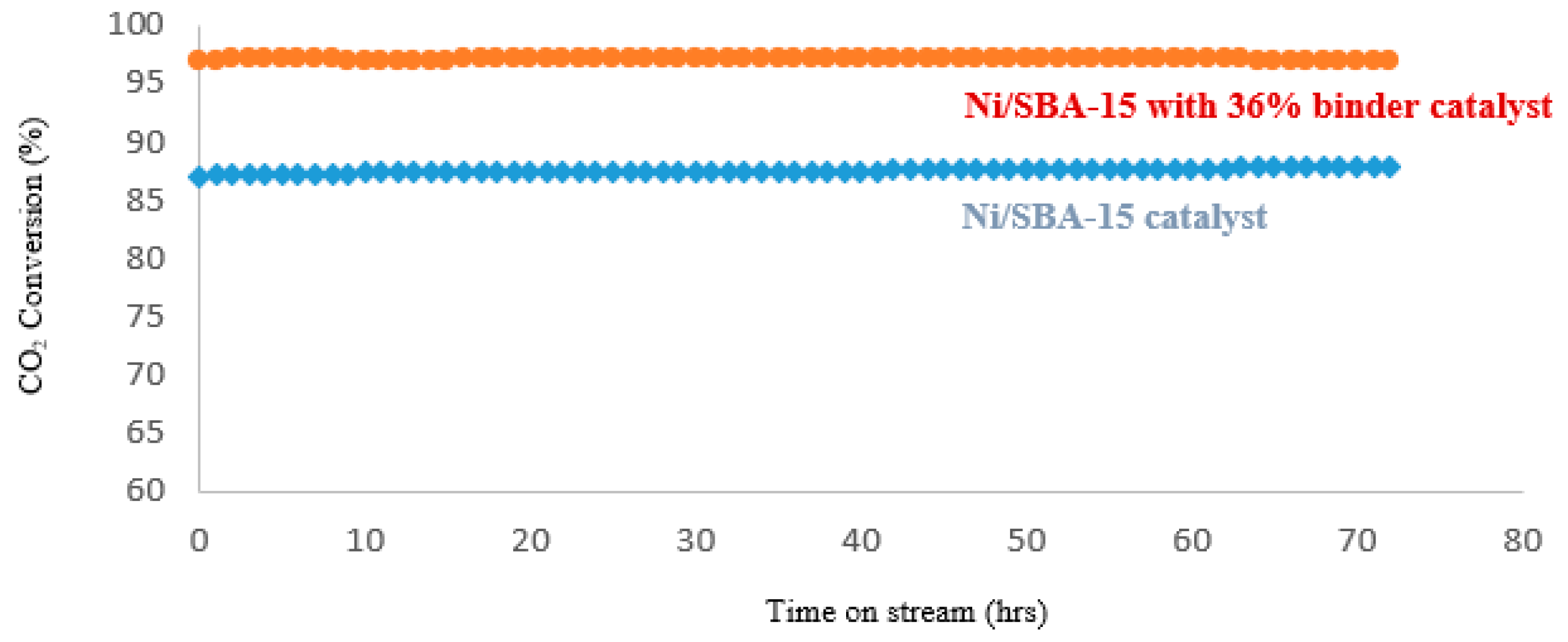

Table 1.
Summary of catalyst pellets preparation.
| No. | Ni/SBA-15 catalyst (g) | Methyl cellulose (g) | Colloidal silica+H2O suspension (g) | Amount of Colloidal silica in Ni/SBA-15 catalyst (%) |
|---|---|---|---|---|
| 1 | 5 | - | - | - |
| 2 | 6 | 5 | 10 | 46 |
| 3 | 7 | 5 | 8 | 36 |
| 4 | 8 | 5 | 6 | 27 |
| 5 | 9 | 5 | 4 | 18 |
| 6 | 10 | 5 | 2 | 10 |
Table 2.
Physical properties of Ni/SBA-15 catalyst.
| Catalyst | BET surface area (m2/g) | Pore size (nm) |
Pore volume (cm2/g) |
Ni loading (wt. %) | Ni size (nm) |
|---|---|---|---|---|---|
| Ni/SBA-15 | 539 | 5.3 | 0.65 | 5.7 | 1- 2 |
Table 3.
Operation conditions used for pyrolysis of dried sewage sludge.
| Pyrolysis at 800 °C | Sewage sludge | Plant operating parameters | |||
|---|---|---|---|---|---|
| Test runs | Moisture content (%) | Density | Residence Time | Feed flow rate (kg/h) | Duration (mins) |
| Test 1 Without catalyst |
7.8 | 0.7 | 20 | 3.7 | 85 |
| Test 2 With Ni/SBA-15 catalyst pellets |
7.8 | 0.7 | 20 | 3.3 | 75 |
Table 4.
Analysis of liquid fraction from pyrolysis of dried sewage sludge before catalytic cracking.
Table 4.
Analysis of liquid fraction from pyrolysis of dried sewage sludge before catalytic cracking.
| Liquid density (g/cm3) |
pH of liquid | Water content (%) |
Tar content (%) |
Nitrogen content (µg/ml) / wt. ppm |
Sulphur content (µg/ml) / wt. ppm |
|---|---|---|---|---|---|
| 1.0347 | 9 | 55 | 45 | 4803 / 4642 |
704 / 680 |
Table 5.
Tar composition before catalytic cracking.
| Tar Compounds | Amount (%) |
|---|---|
| Light aromatics excluding benzene | 22.2 |
| Pyridine | 20.2 |
| Dimethylpyrazine | 9.2 |
| Acids | 9.1 |
| Aliphatic | 7.4 |
| Phenol | 3.6 |
| 4-Pyridiamine | 3 |
| Others | 25.3 |
Disclaimer/Publisher’s Note: The statements, opinions and data contained in all publications are solely those of the individual author(s) and contributor(s) and not of MDPI and/or the editor(s). MDPI and/or the editor(s) disclaim responsibility for any injury to people or property resulting from any ideas, methods, instructions or products referred to in the content. |
© 2025 by the authors. Licensee MDPI, Basel, Switzerland. This article is an open access article distributed under the terms and conditions of the Creative Commons Attribution (CC BY) license (http://creativecommons.org/licenses/by/4.0/).
Copyright: This open access article is published under a Creative Commons CC BY 4.0 license, which permit the free download, distribution, and reuse, provided that the author and preprint are cited in any reuse.


