
Submitted:
30 December 2024
Posted:
31 December 2024
You are already at the latest version
Abstract
The aim of this paper is to provide insight into the drivelines of today's electric passenger and heavy-duty vehicles and to understand the sources of power losses in these driveline gearboxes. Knowing the losses that occur in a gear drive gives us the opportunity to reduce them. This means longer range and longer lubricant life. It can be seen that it is important to address gear oil lubrication losses, reducing them means less frequent oil change intervals and therefore lower maintenance costs. The article also highlights further areas for research and provides a comprehensive insight into the design of electric vehicle powertrains.
Keywords:
electric vehicle drivetrain
; gear drives
; oil churning loss
; gear losses
; efficiency
; windage losses
; seal friction
1. Introduction
In modern electric vehicles, we find a wide variety of drive trains. There are constant ratio and variable ratio gearboxes. In the case of gearboxes with selectable ratios, there are usually two speeds to provide the appropriate speed range for the vehicle. The powertrain of electric vehicles is therefore of a much simpler design than that of their conventional internal combustion engine-powered ones. For conventional vehicles, there are several manual, robotised or semi-automatic (6 to 8 speeds), DSG (double clutch), CVT gearless (continuously variable transmission), D-CVT direct shift CVT, and toroidal variator. The eCVT powertrain developed for hybrid vehicles can achieve excellent power sharing and summation between the internal combustion engine and the electric motor. Of course, electric vehicle manufacturers have also developed a variety of powertrain designs for both passenger cars and heavy-duty vehicles. Electric vehicle manufacturers seem to have had to switch to producing components for electric cars in an extremely short time. It is true that the major manufacturers had predicted the direction of development well in advance, but to the outside eye the time to market for the redesigned products was quite rapid. It is also important to know that the machine components, which are the building blocks of the machines, are compatible to a certain extent at a certain level. For example, if we look at either a dry or a wet clutch [1], we can already see that the geometry, production technology and materials used for the main components are similar, and often identical. The same clutch disc housing, or differential, is used by manufacturers for several models, for several different power units.
The main target functions in the development are to eliminate running noise and increase range. One of the most effective ways to increase range is to increase the efficiency of the system. However, to assess the efficiency of a complex system, we need to know the exact source of the losses. To do this, we also need to know the exact design of the engine under test. It is therefore important to understand the powertrain developments of vehicle manufacturers so that their performance losses can be taken into consideration. One of the main objectives of this article is to provide researchers with a comprehensive overview of the development directions to be taken in this area, the state of the art and the theoretical background of efficiency calculations. Our aim is to provide basic ideas for further research in this summary article.
2. Reasons for the Simplicity of Electric Vehicle Powertrain Designs
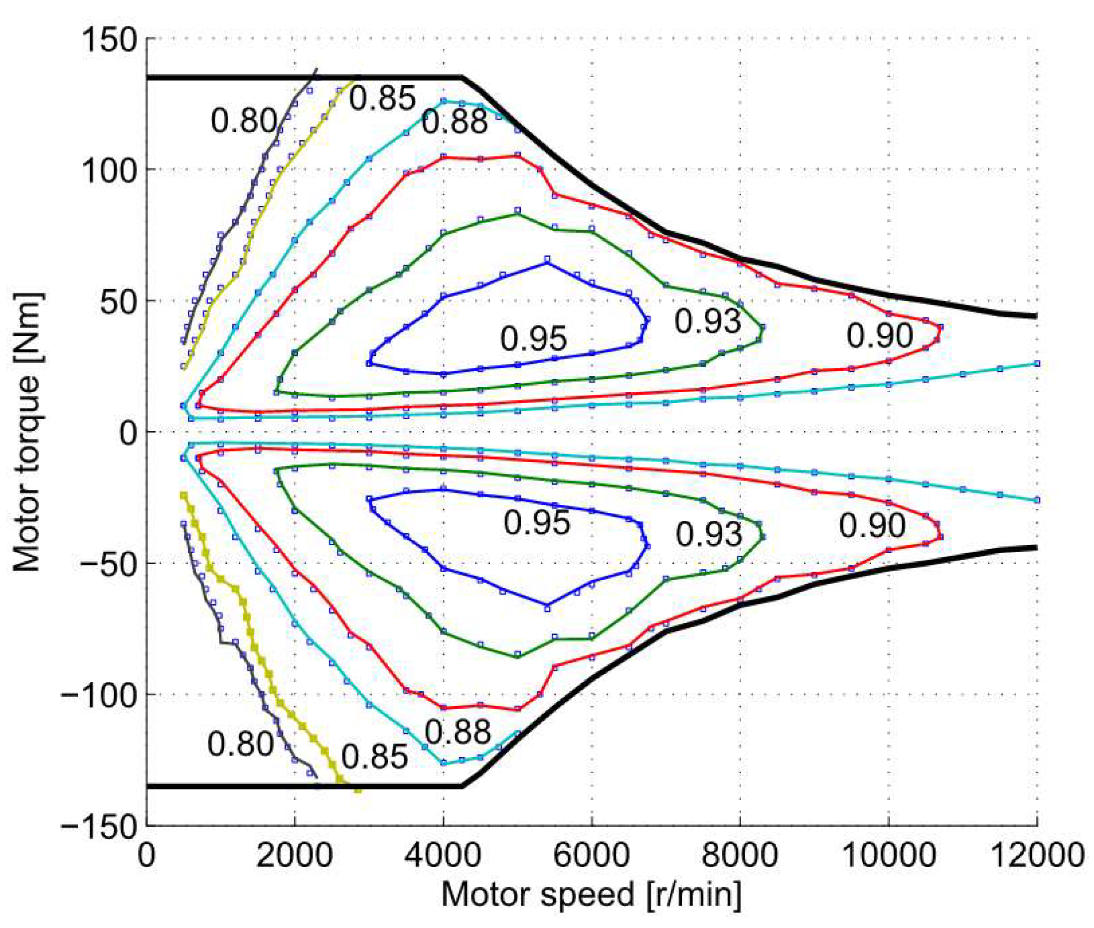
The simplicity of electric vehicle gearboxes is largely due to the characteristic curve of the power source, the motor. Compared to the characteristic curve of a conventional internal combustion engine, the characteristic curve of an electric motor provides a more optimal torque distribution and a wider speed spectrum. The characteristic curve shows that the maximum torque of the engine is available from the moment of starting, that the speed range is very wide and the efficiency is also favorably high. For example, the Tesla Model S engine speed can range from 0–18000 rpm. Compared to an internal combustion engine for an average passenger car, this is a significantly wider range. Gasoline engines have an average maximum engine speed of 6000–7000 rpm, diesel engines even less, on average 4–5000 rpm. In addition, combustion engines can deliver maximum torque and power over a given speed range, but their characteristic curve shows a rather drastic drop in efficiency (either in consumption or in low torque output) outside the optimum range. The narrow optimum operating range of internal combustion engines means that emissions can only be reduced by the introduction of several torque converters with discrete modifications. This explains today’s trend towards a steady increase in the number of gears in the vehicle’s engine, from 3 to 4 gears in the beginning to 6 to 10 gears today. This is understandable, of course, since the more the engine’s characteristic curve is finely approximated by the more gears, the more favorable the driving dynamics become. In contrast to internal combustion engines, electric motors in vehicles can deliver maximum torque at low engine speeds and have a much wider speed range. The average car has a 101.5 kW power source and transmission of 180 kg, giving a power density of 0.564 kW/kg, compared to Tesla’s 31.8 kg, 262.5 kW motor, which gives 8.253 kW for every kilogram. This is one of the reasons why the electric vehicle engine does not require any structural stages.
Figure 1.
The characteristic curve of a typical PM permanent magnet motor [2].
Figure 1.
The characteristic curve of a typical PM permanent magnet motor [2].
3. Advanced Electric Car and Heavy Vehicle Engines
Fixed Ratio Gearboxes, Tesla and GKN Gearbox Types
Porsche was many decades ahead of its peers and one of its very first cars had four electric wheel hub motors, but perhaps one of the best-known pioneers of our time is Tesla. Its predecessor, the Model S, also needs just 2.28 seconds to reach 60 miles per hour, making it one of the top three fastest production cars in 2018. Despite serious, and certainly exaggerated, performance figures for everyday use, the powertrain is extremely simple. But it’s not just the Tesla Model 3 that has a simple constant-ratio gear train, it’s also found in the Nissan Leaf, the Volkswagen ID.4, the Mercedes EQS SUV and the BMW iX.
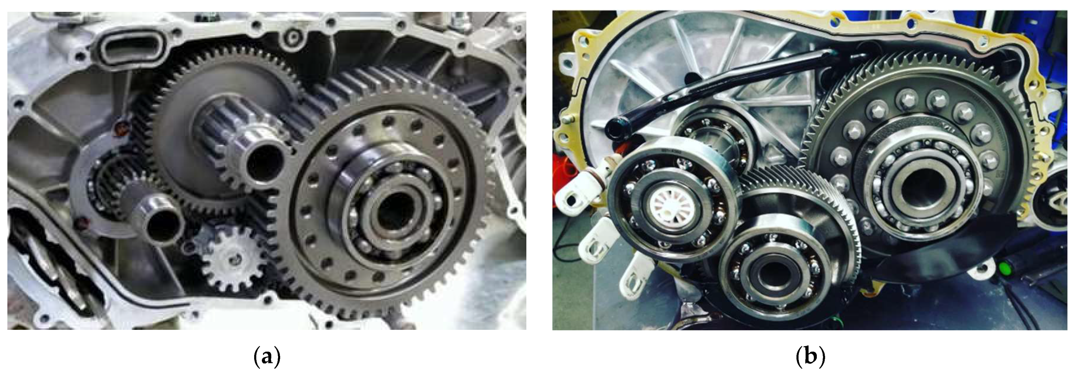
Tesla’s gear drive is a simple two-stage, constant (i = 9.73) ratio, helical geared cylindrical gear unit. The gear axles are supported by simple deep groove ball bearings.
The gears are helical gears to reduce noise levels, but of interest is the prototype shown on the left of the figure below, which still has spur gears.
Figure 2.
A prototype with straight teeth (a), on the right the current production design (b) [2].
Figure 2.
A prototype with straight teeth (a), on the right the current production design (b) [2].
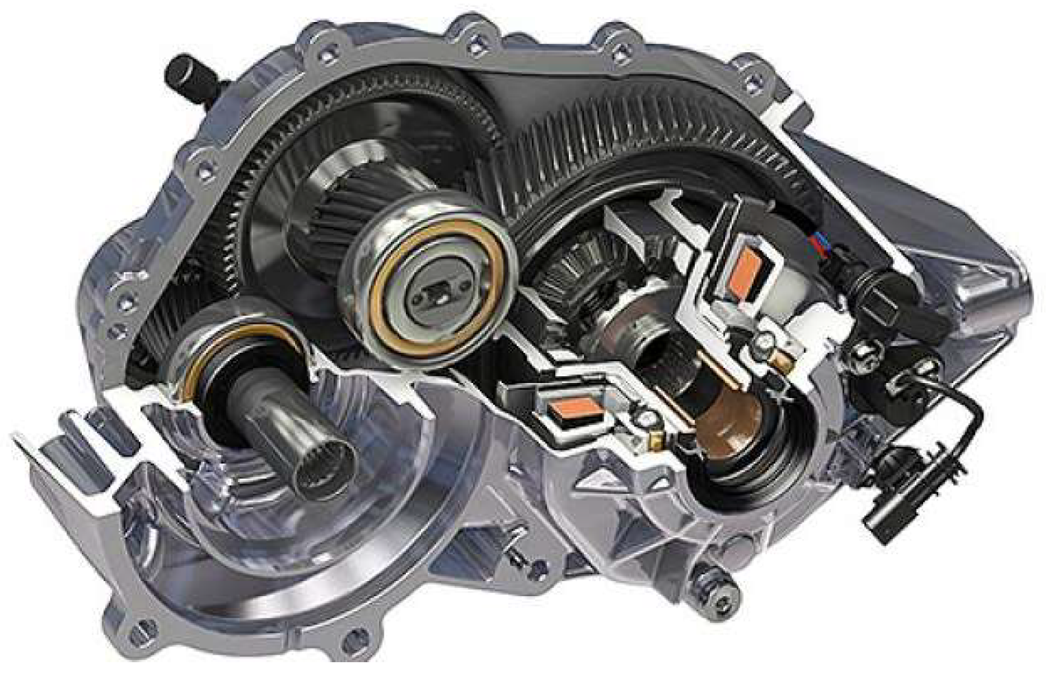
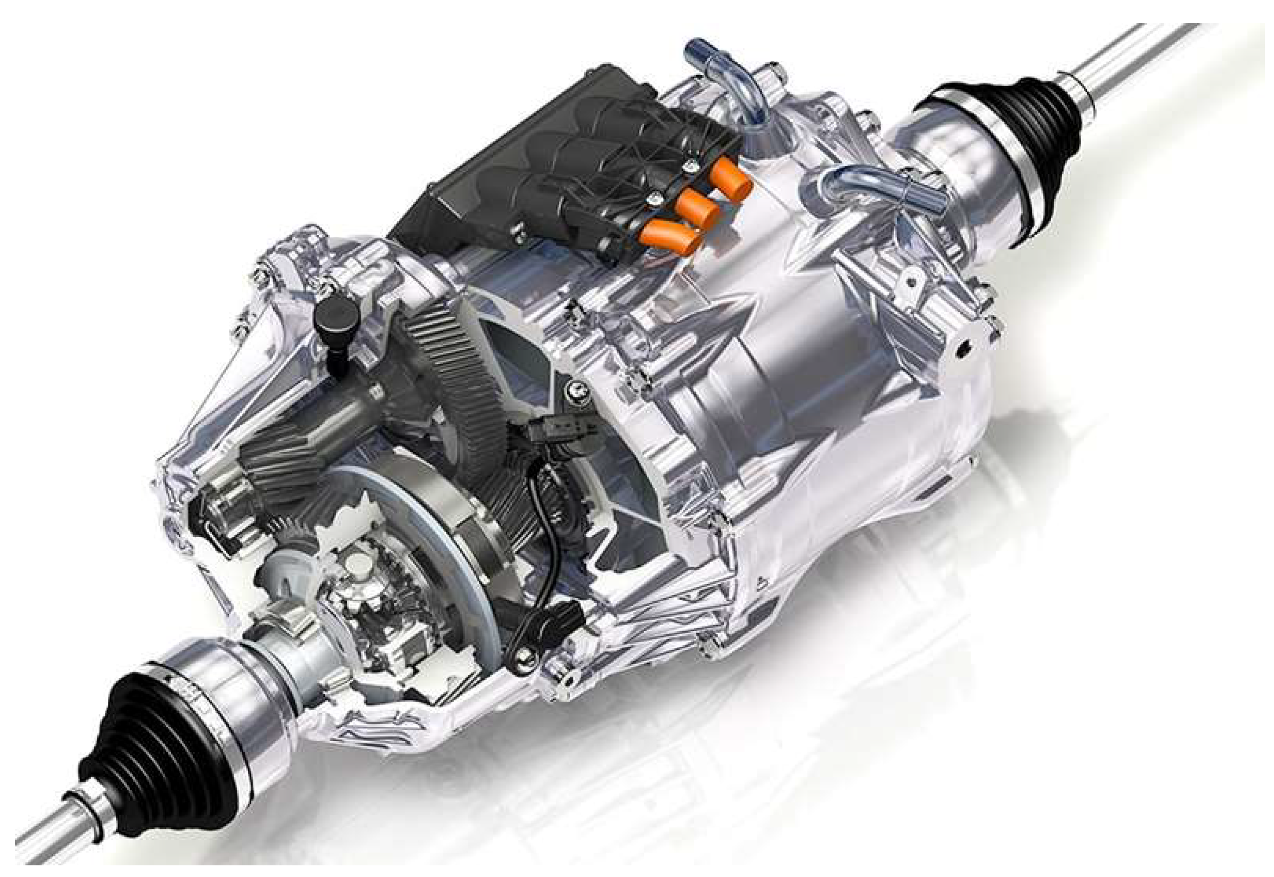
The gearbox is fitted with a conventional open differential. The traction control is software-controlled with energy dissipation and selective braking.
Figure 3.
Simple construction and open differential as the final drive [2].
Figure 3.
Simple construction and open differential as the final drive [2].
GKN is one of the top 100 automotive suppliers [3]. As early as the 1950s, they produced engines for the Jaguar XK120, later for the Mini, and today for car manufacturers such as Jeep, BMW and Porsche. Today, they are also among the best in electric propulsion, with several solutions for different types of cars.
GKN Gen II eAxle Constant Ratio Gearbox
This type is used in the BMW 2 Series Active Tourer 225xe. Its operation is similar to that of the Tesla in that it is a fixed-ratio gearbox with two-stage (having two gear pairs), but the differential can be disengaged from the drive.
The whole unit weighs 20.2 kg, has a length of 457 mm, a width of 229 mm and a height of 259 mm.
The i = 12.5 gear ratio is capable of accelerating the BMW 2 Series to 125 km/h, so this drive is not an all-electric but a hybrid type. At higher speeds, an electromechanical clutch disengages the electric drive to minimize power loss from the reverse drive and to protect the drive from failures caused by lubrication inadequacy and excessive heat build-up due to excessive revs. During braking, the clutch reconnects the system to allow the energy generated during braking to be recharged to the battery. In this case, only the internal combustion engine is responsible for propulsion. GKN’s software is responsible for the transition between all-electric, hybrid and all-combustion operations. The electric motor drives the rear axle, the combustion engine the front. The maximum torque is 2000 Nm, delivered by a 64 kW electric motor. The mechanical efficiency of the system is favorable at around 96%.
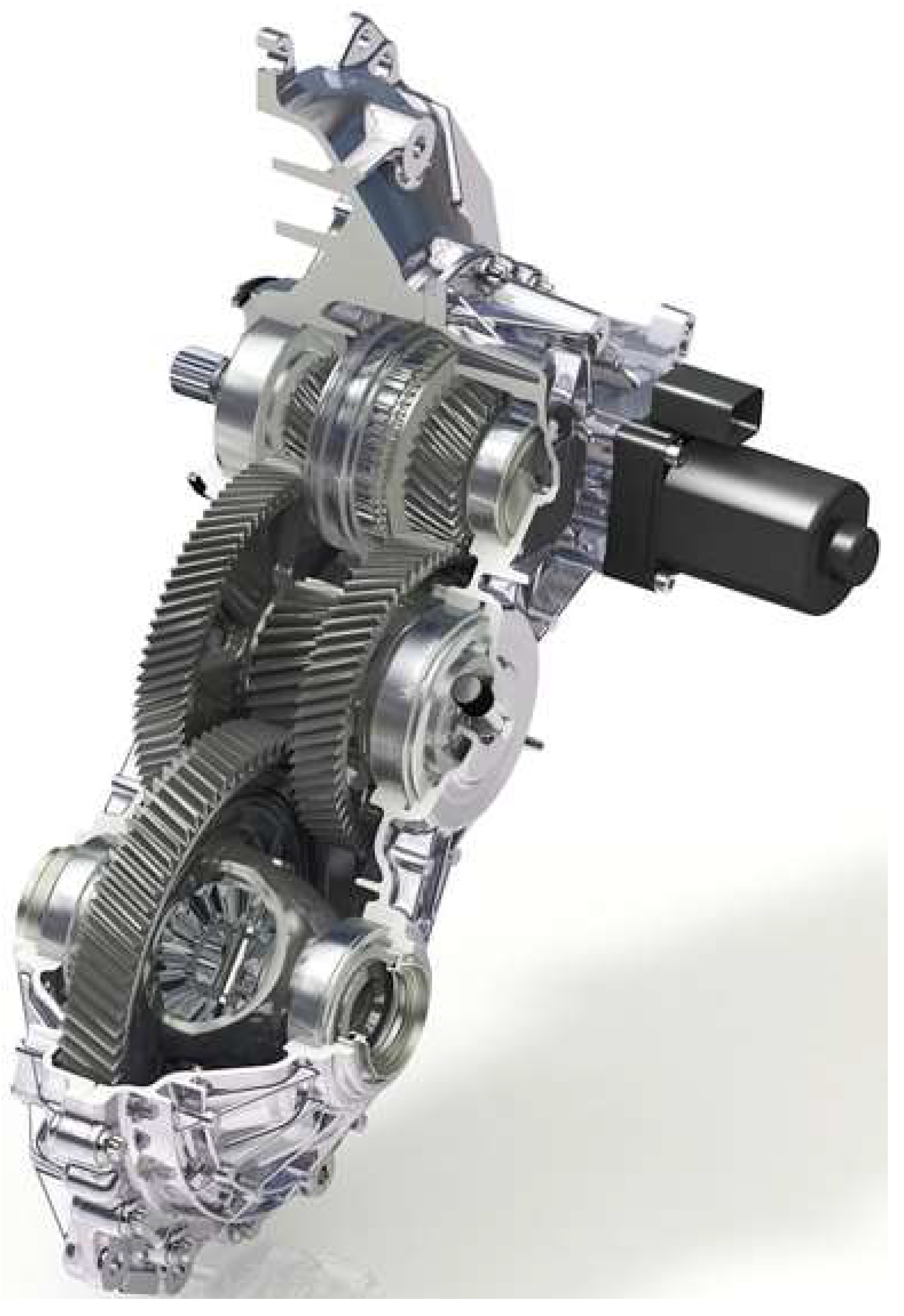
GKN Co-Axial eAxles
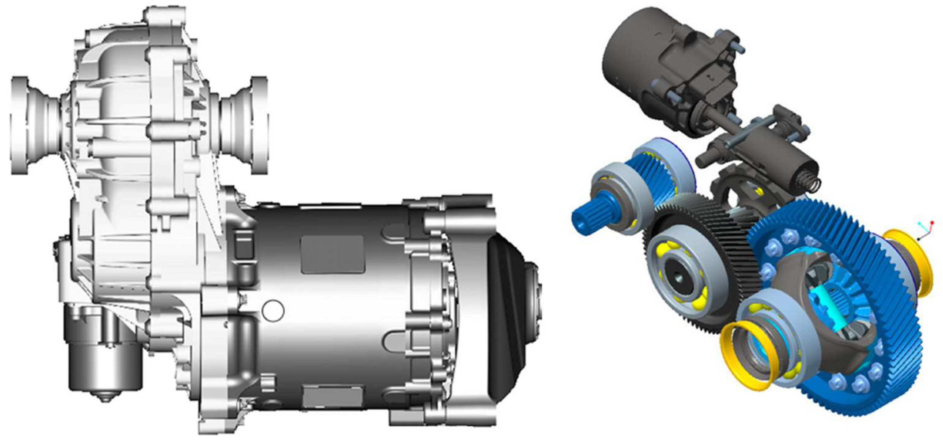
This system is fitted to Volvo XC90 T8 Twin Engine models. Plug-in hybrid, PHEV technology for short, so like the GKN two-speed eAxle engine, it has both an internal combustion engine and an electric motor and also feeds energy generated during braking back into the batteries (regenerative breaking).
Figure 5.
GKN gearbox with co-axial construction [6].
Figure 5.
GKN gearbox with co-axial construction [6].
This powertrain is also offered for hybrid and electric cars. The gearbox and the electric motor form a single unit for compactness. To save space, the motor’s output shaft is toothed, forming a direct drive shaft and drive gear for the gearbox first stage. As with the GKN Gen II eAxle, an electromagnetically controlled clutch in the differential disconnects and deactivates the electric drive in the higher speed range. The drive is located on the rear drive axle. In the Volvo XC90, the front axle is driven by an internal combustion engine, so this model is also all-wheel drive. Thanks to helical gears, the noise level is low. The engine has an efficiency of 97.5%, a maximum torque of 2400 Nm, and overall dimensions of 263 mm × 310 mm × 293 mm. Without lubricating oil, the total weight is 15 kg.
Two-Speed Gearboxes with Optional Gear Ratio
Although Tesla engineers also developed a switchable two-speed gearbox, they found it structurally complex and costly, so they stuck with a fixed gear ratio. Of course, other car manufacturers are trying to add value to their developments. So did the Audi e-tron GT and the all-wheel drive Porsche Taycan. These models boast two complete drivetrains. The constant-ratio drive to the front wheels is for everyday cruising, the first, high-ratio gear of the two-speed drive to the rear wheels is for maximum acceleration in sport mode, while the second gear is for high efficiency in high-speed cruising. From a design point of view, the key difference is that the two gears are either a forced-synchromesh mechanism or a double-clutch construction, similar to DSG gearboxes.
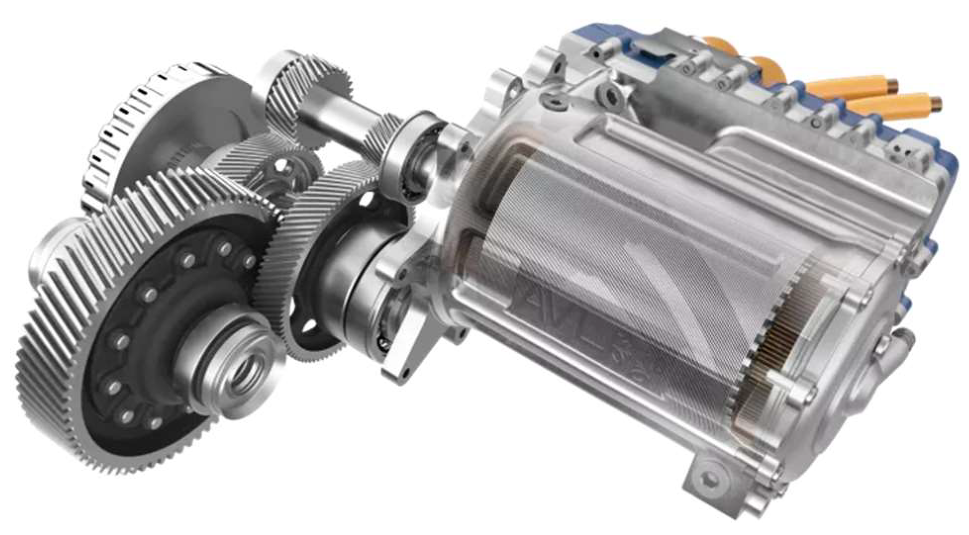
GKN Two-Speed eAxle Gearbox
This transmission is used in sports cars, where maximizing performance is a priority. An example is the BMW i8 hybrid.
Figure 6.
Two-speed gearbox with a forced-synchromesh mechanism [2].
Figure 6.
Two-speed gearbox with a forced-synchromesh mechanism [2].
The gearbox is rated by the manufacturer at 97% efficiency, maximum torque 2800 Nm, mass 27 kg, enclosure dimensions 325 mm × 562 mm × 313 mm. The gear ratio of the first gear is i1 = 11.38, the second gear i2 = 5.85. The gearbox mechanism is located on the input shaft together with the conventional Borg-Warner forced synchronous mechanism.
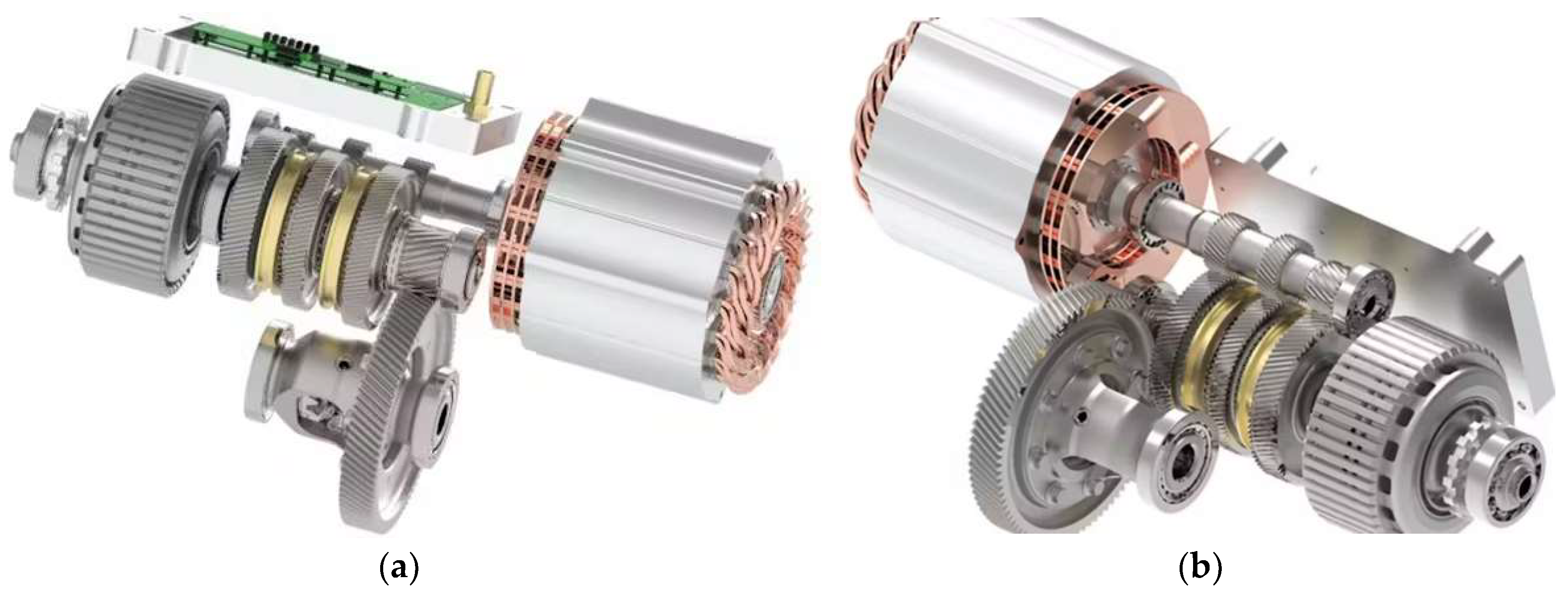
AVL Two-Speed Gearboxes with Double Clutch
AVL has also developed several types of gearboxes for electric passenger and heavy-duty vehicles. One such two-stage gearbox with a double clutch selector mechanism is shown in the figure below.
Figure 7.
Two-speed drivetrain for EV (electric vehicle) by AVL [7].
Figure 7.
Two-speed drivetrain for EV (electric vehicle) by AVL [7].
Multi-Speed Drives
Naturally, manufacturers try to keep the motors in the most optimal operating range. This is achieved by including as many gears as possible to cover the entire speed range.
Figure 8.
Three-speed gearbox from Ricardo engineers [8].
Figure 8.
Three-speed gearbox from Ricardo engineers [8].
Hybrid Drive Trains
- Toyota Prius
Toyota started production of the first Prius in 1997. The Toyota Hybrid System, the car’s drive system, was developed to reduce emissions. By combining an internal combustion engine with an electric motor and generator, Toyota has achieved a technology that was at the cutting edge of technology in the 1990s without significantly changing the size or weight of the car. The Prius incorporates the basic components of a conventional car engine, with the addition of the elements needed for hybrid propulsion.
Figure 9.
The Toyota Prius powertrain concept [https://www.researchgate.net/figure/Schematic-of-Toyota-Prius-powertrain_fig2_281675229].
Figure 9.
The Toyota Prius powertrain concept [https://www.researchgate.net/figure/Schematic-of-Toyota-Prius-powertrain_fig2_281675229].
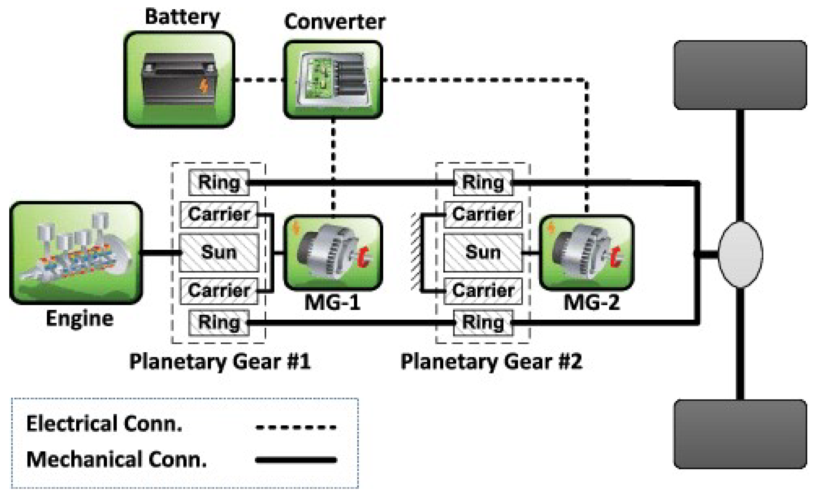
The Toyota Prius 1.5 HSD has a 1500 cm3, 55.1 kW, four-cylinder internal combustion (gasoline) engine. Thanks to regenerative braking, the alternator generates electricity which is stored in the battery. The electric motor produces a further 48.56 kW and 400 Nm of torque. The energy from the two motors is combined by a power splitter planetary gearbox, allowing the car to be driven either separately or by the electric motor and internal combustion engine simultaneously. The electric motor, designated as the alternator, is also responsible for starting.
The planetary gear’s sun wheel is connected to the internal combustion engine’s alternator, its ring gear to the electric motor and its planetary gear lever to the internal combustion engine. This allows the two engines to run in parallel, their power being added together thanks to the planetary gear.
Figure 10.
A simple planetary gear for splitting or summarizing the power of the motors [9].
Figure 10.
A simple planetary gear for splitting or summarizing the power of the motors [9].
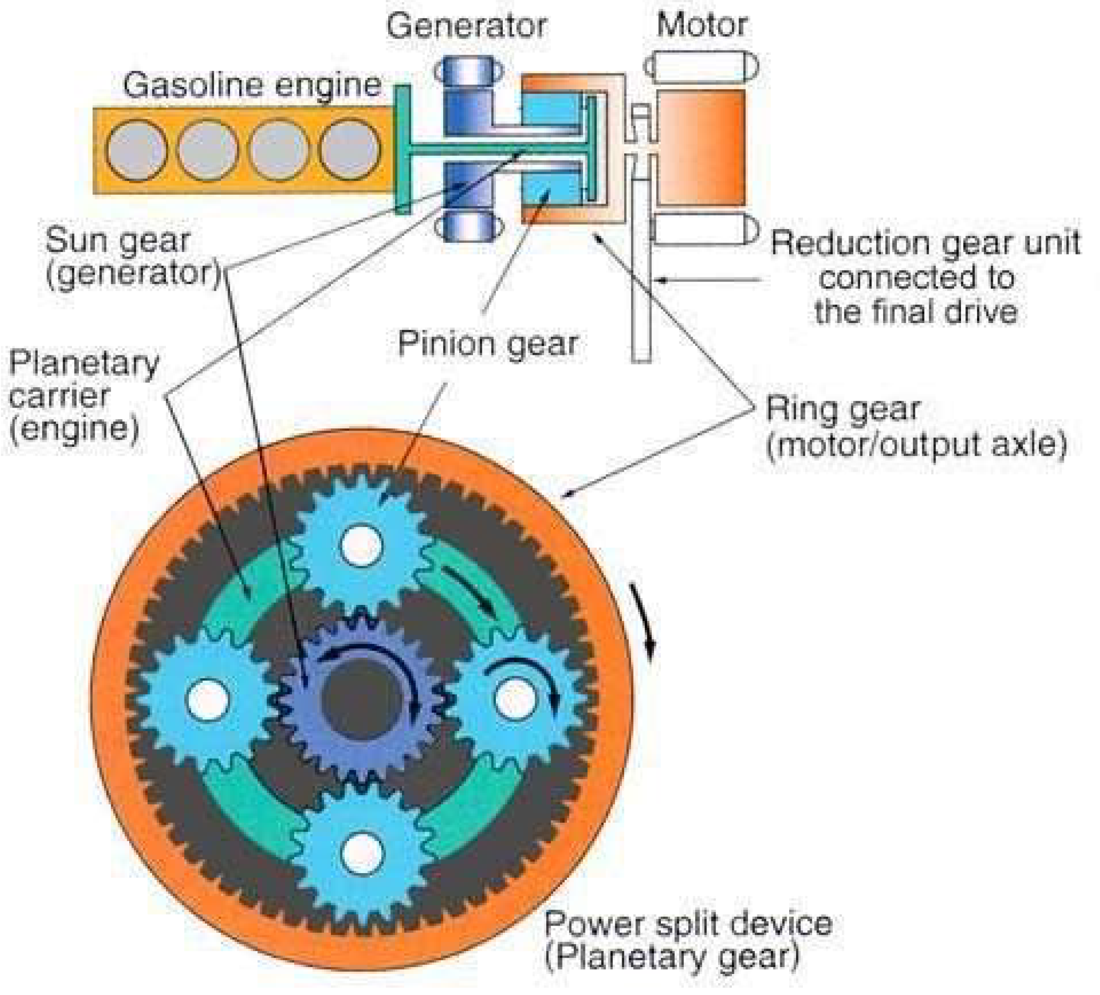
Figure 11.
Toyota Gen2 CVT and Gen3 eCVT drivetrains without the differentials [10].
Figure 11.
Toyota Gen2 CVT and Gen3 eCVT drivetrains without the differentials [10].
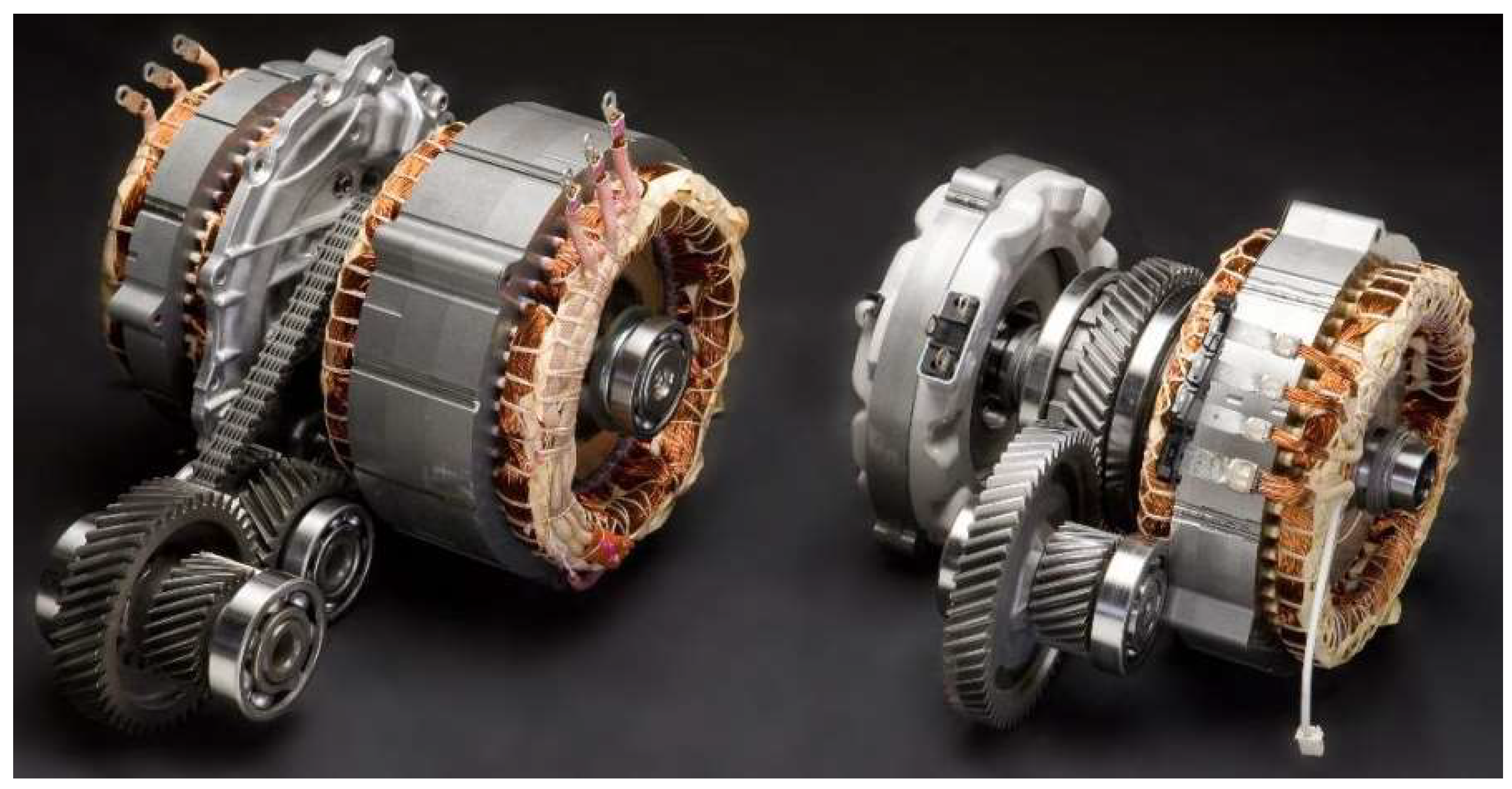
The third-generation Prius now features a new technology called eCVT. The “e” refers to the electric transmission of the gearbox. The mechanical transmission is fixed, with no conical pulleys or special chains. The virtual transmission is controlled by a computer. The alternator generates electricity and feeds a high-torque electric motor that drives the wheel axles through the gears. The speed of the electric motor is adjusted by computer control to the desired speed of the car. In most cases, the electric motor drives the car, while the engine is responsible for charging the battery and powering the alternator. The internal combustion engine only drives when its fixed gear ratio is optimal. At cruising speed, this corresponds to gears 3 and 4 for normal petrol cars. At this point, the electric motor provides hardly any torque, and the petrol engine mostly does the work.
Multimode eTransmissions
The following gearbox, like the previous ones, allows a combination of an electric motor and an internal combustion engine. Three different modes are available: all-electric, series hybrid, parallel hybrid or combustion engine only. Its special feature is that it has 2-2 outputs and inputs. Its two input shafts are used by the two drive motors, and its two output shafts are used by the driven wheel axle and the generator that charges the battery for the electric drive.
Figure 12.
Multimode eTransmission [11].
Figure 12.
Multimode eTransmission [11].
The pure electric mode can accelerate the car to 116 km/h or put it into reverse. In this mode, the combustion engine is completely disconnected from the drive.
In series hybrid mode, the internal combustion engine drives the alternator, thus charging the battery. This mode is activated when the battery charge is low or when high power is needed.
In parallel hybrid mode, the combustion engine and the electric motor drive together thanks to the hydraulic clutch. In other modes, the clutch is disengaged. The maximum torque of the drive unit is 2000 Nm. The combination of modes results in extremely good fuel consumption. At average cruising power, only 1.5 litres of fuel are required to cover 100 kilometres. The car is also fitted with two power units, one for the front axles and one for the rear axles.
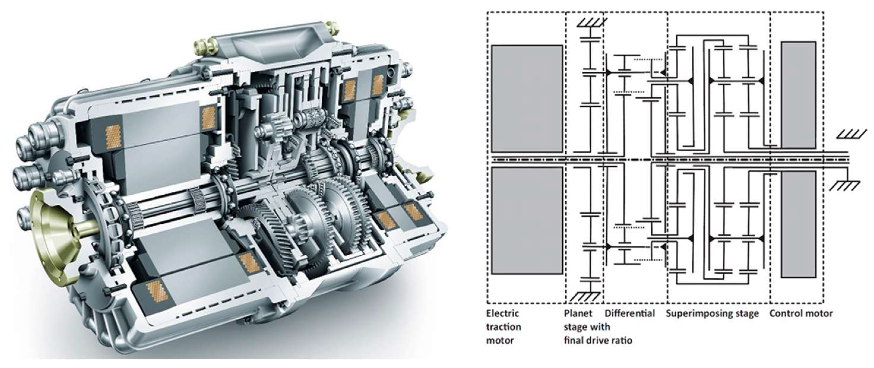
Schaeffler Planetary Gearbox with Spur-Geared Differential
The gearbox contains three planetary units, one of which is the differential itself, the other two units control the torque distribution between the drive shafts by means of a control or auxiliary motor.
Figure 13.
The Schaeffler planetary coaxial ACTIVeDRIVE gearbox with electric differential [12].
Figure 13.
The Schaeffler planetary coaxial ACTIVeDRIVE gearbox with electric differential [12].
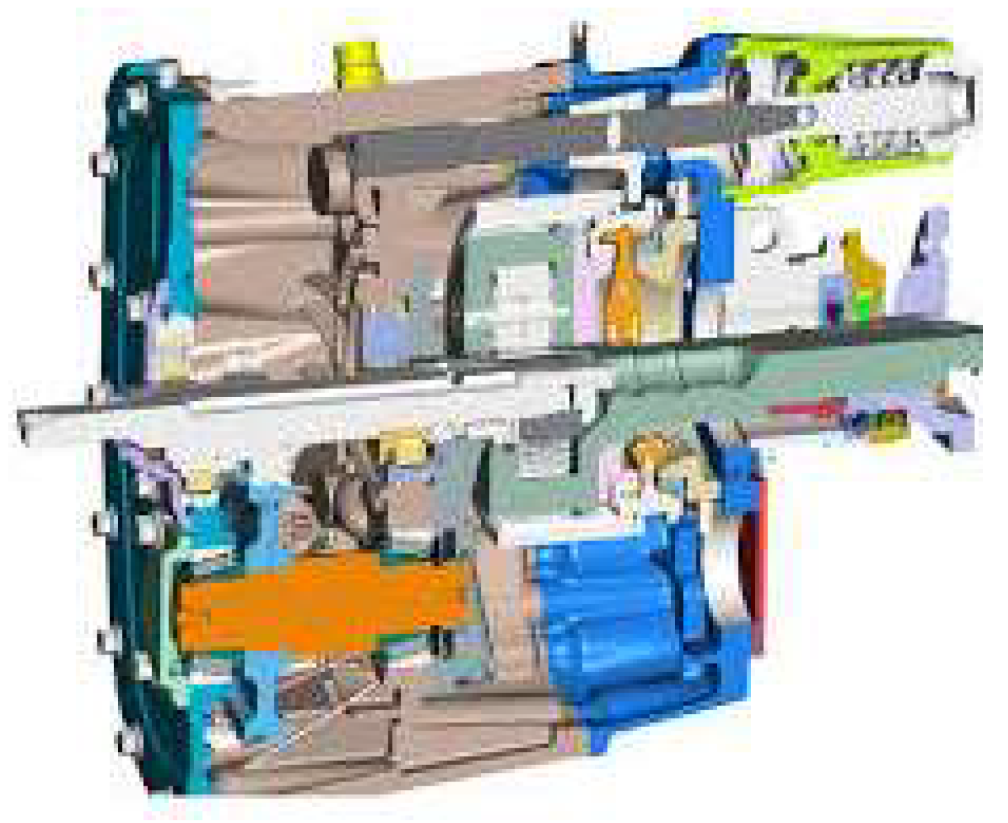
Because of their high-power density and high efficiency, planetary gears are not only being used in passenger cars but also in the drivelines and hub drives of electric heavy vehicles.
UQM Technology
Figure 14.
Eaton two-speed (a) and four-speed (b) gearboxes for buses [13].
Figure 14.
Eaton two-speed (a) and four-speed (b) gearboxes for buses [13].
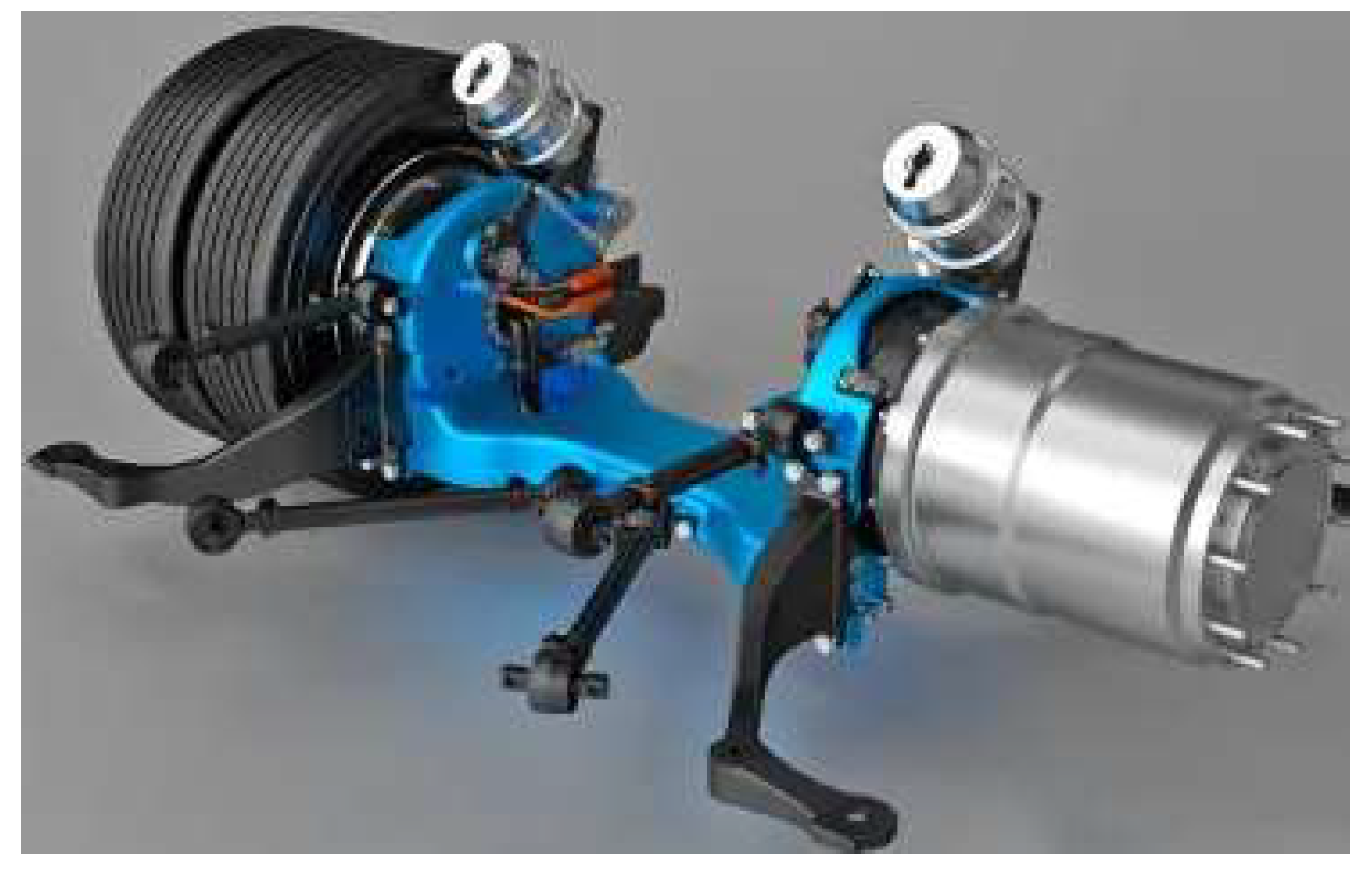
One of the main developments in the field of heavy-duty vehicle powertrains has been the wheel drive. Wheel drive raises very delicate issues and it is not at all useful to subject a complex drive system to the high dynamic loads of a wheel with a swinging inertia.
Figure 15.
Planetary wheel hub drives for heavy-duty trucks and buses [14].
Figure 15.
Planetary wheel hub drives for heavy-duty trucks and buses [14].
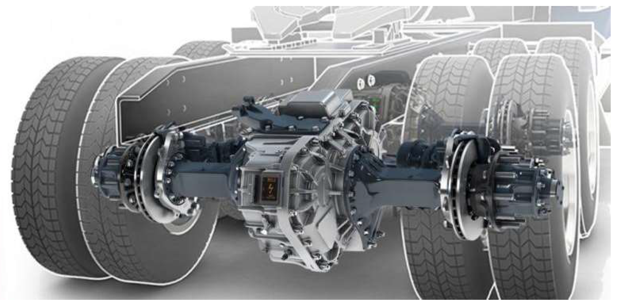
To overcome the disadvantages of wheel hub drives, manufacturers have developed electrically driven rear bridges. A particular challenge in this development is to ensure that the driving dynamics of the retrofitted vehicles are not changed, or at least only minimally, to improve drivability. Weight is also important, as it is not advisable to install a very heavy drivetrain at the expense of payload.
Figure 16.
Electric rear bridge for trucks [15].
Figure 16.
Electric rear bridge for trucks [15].
4. Development Areas, Opportunities
In modern gear drives, the focus is increasingly on reducing noise and vibration levels, increasing efficiency and gearbox lubrication efficiency, and increasing load capacity. Knowledge of the gear efficiency and the resulting temperature distribution is particularly important for high-load, high power-density gear planetary gears, which have a small heat-dissipating surface and can easily overheat without cooling. Almost all of the power losses due to friction, lubricant churning and windage losses are converted to heat, which increases the gearbox temperature. Excessive temperature rise can cause deterioration of the lubrication condition, chafing of tooth surfaces, reduced lubricant life, even damage, and exceeding the thermal capacity of the gearbox. Although the currently known power loss of electric drive trains is only 15 to 20% of installed power, compared to 64 to 75% of conventional internal combustion engines, according to U.S. Department of Energy sources, it is important to reduce these losses to reduce costs, reduce our ecological footprint and increase range.
5. Power Losses of Gear Drives
Accurate calculation of gear losses is a complex task: it requires a complex knowledge of the structure, mechanics, tribology, hydrodynamics and thermodynamics. The friction of the associated gear teeth accounts for the largest part of the losses, but bearing friction is also significant, and in high-load, high-speed gearboxes, losses due to oil mixing, sealing and possibly drag must be taken into account.
Gearbox Gear Efficiency
The power loss of a gear drive is determined by tooth friction loss, bearing friction loss, lubricant churning loss, windage loss and seal friction loss. It can be written symbolically as follows [16]:
The most significant is the tooth friction loss Pz, for which several methods have been developed and used in practice [16,17,18,19,20,21,22,23,24,25,26,27,28,29,30,31,32,33,34,35,36,37,38,39,40,41,42,43,44,45,46,47,48,49,50,51,52,53,54,55]. The relationships are usually derived using the friction forces and sliding velocities during tooth contact, assuming an average tooth friction coefficient.
For example, Niemann and Winter [19] described the following relationship for calculating the power-dependent tooth friction loss Pz:
where Hv is the loss factor considering the tooth contact conditions:
The gear efficiency, tooth friction loss Pz and idling loss Pz0 are also taken into consideration:
Regarding the friction force on the tooth, the sliding relations of the teeth and a constant tooth coefficient of friction, Duda [20] derived the proposed relation for calculating the gear efficiency of an involute gear pair, which includes the number of teeth and the geometric relations of tooth contact: the partial transverse contact ratios. In technical practice, in most cases, the partial transverse contact ratios are less than 1. Then, according to Duda, the relation can be written in the following form:
The (+) sign applies to the outer gearwheel connection, and the (-) sign applies to the outer-inner gearwheel connection. The tooth friction coefficient μz used in the relationships presented in the calculation of gear efficiency is based on experience or measurements. Its exact calculation is also a complex task because its value depends to a large extent on the friction condition: lubricant and lubrication method, operating conditions: load, speed, temperature, and gear material, design, surface condition, roughness. A suitable correlation is given, for example, in ISO TC 60 for the determination of the average coefficient of friction [24]:
Calculating the Bearing Friction Losses
Several researchers have worked on the determination of friction loss in rolling bearings, including Stribeck [56], Palmgren [57], Bartels [58,59], Eschmann [60], Gupta [61], Hansberg [62], Hollatz [63], Jörg Koryciak [64], Korrenn [65], Liang [66], Potthoff [67], Scherb [68] and Siepmann [69]. The first relation for the calculation of friction loss in rolling bearings was given by Stribeck in 1901.
By separating the performance-dependent and independent loss components and by an extensive study of the parameters influencing the losses, one of the most widely used models was developed by Palmgren.
In recent years, SKF has developed a new, more accurate calculation model [56] for the calculation of friction losses in rolling element bearings, which takes more parameters into account than the previous one but increases the number of calculations. Accurate calculation of bearing losses is particularly important for electric vehicles, where high bearing efficiency is a prerequisite due to the high system efficiency [70]. In the case of electric vehicle bearings, practical tests should also be carried out to check that leakage current does not cause bearing damage [71].
Oil Churning Losses of Gears
The oil churning work of a gear immersed in lubricant increases the power loss, which is very difficult to calculate given the complex and complicated flow conditions. Several researchers have developed models to calculate oil churning loss, for example, Niemann [19], Yasutsune Ariura [72], Taku Ueno [73], Walter [74], Mauz [75], Terekhov [76,77], Maurer [78], Dick [79], Sax [80], Schimpf [81], Leimann [82,83], Lauster [84], Butsch [85] and Dirk Strasser [17]. Niemann [19] gave an approximate relation for cylindrical and conical gear pairs. For the determination of oil churning losses in high-performance gear drives, Terekhov and Spitko [76,77] derived, based on the laws of fluid mechanics, relations which consider the oil churning loss as the sum of the losses due to oil expel and disc friction losses. Dirk Strasser [17] measured the oil expel loss components due to oil displacement and disc friction as a function of speed. Butsch [85] was the first to develop a model for calculating oil churning losses in gears. C. Changenet [35] (based on Boness’ equations) derived the following relation of the oil churning loss torque Mch for immersion lubrication:
where the dimensionless torque CTQ, depending on the flow conditions, can be calculated as follows:
If:
If:
If the Reynolds number is 6000 <Rec <9000, the value of CTQ and Mch can be determined by linear interpolation between the above values.
C. Changenet et al., also investigated the effect of the axial and radial clearance between the housing surrounding the gears and the wheels on the oil friction losses. Theoretical relationships were described and their validity was verified by measurements.
Dirk Strasser wrote his doctoral thesis on the influence of tooth head and tooth root clearances on oil friction losses [1]. He investigated in great detail the influence of tooth clearances, geometry and speed conditions on oil friction losses on his own designed measuring equipment. Using a simple hydrodynamic model to approximate the tooth connection, he has described the relationships for the calculation of oil churning losses.
Using the measured results, he determined the following relationships of oil expel and disc friction torque losses for immersion and injection lubrication by regression analysis.
Disc friction loss torque for the drive shaft:
The loss of oil expels:
where the CTQ torque factor is given by the following relationship when the small wheel does not reach the oil level:
In the event that both wheels are partially (13) or completely (14) submerged in the lubricant:
where the reference values are: ν0 = 1 [mm2/s]; e0 = 0,1 [l/min]; vrw0 = 1 [m/s].
The oil lubrication work in gears also places considerable stress on the oil, mechanical stress is dangerous for the molecular structure, the resulting significant temperature rise is problematic from an oxidation point of view, and the resulting wear also reduces the service life of our lubricating oil. The oil churning losses are also presented and the expeled and squeezd oil volume is calculated in [86].
Figure 17.
Oil expel (both sides of the gear tooth contacts), oil churning and disc churning losses (both sides of the gears) of the spur (a) and helical (b) gears [17].
Figure 17.
Oil expel (both sides of the gear tooth contacts), oil churning and disc churning losses (both sides of the gears) of the spur (a) and helical (b) gears [17].
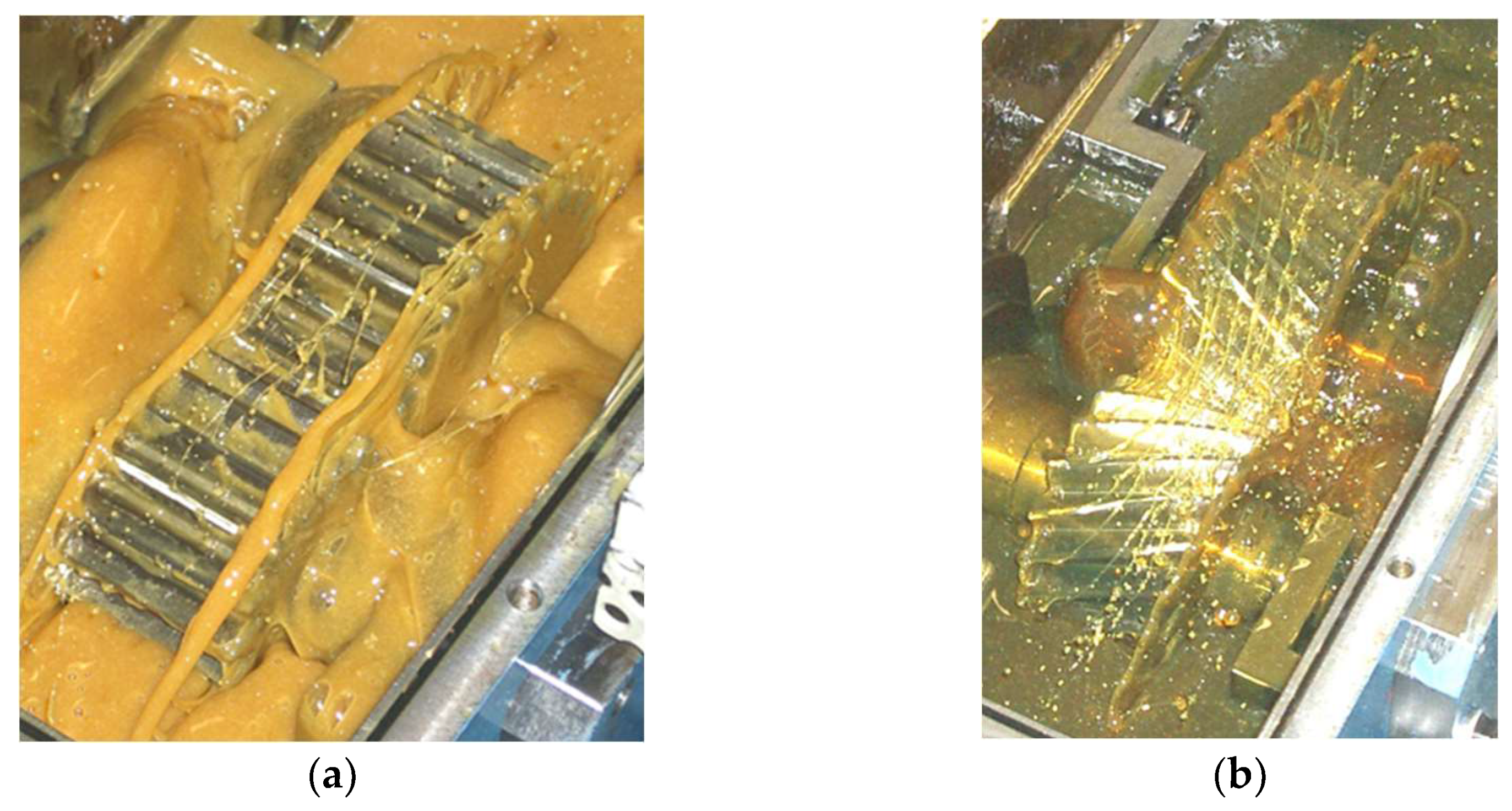
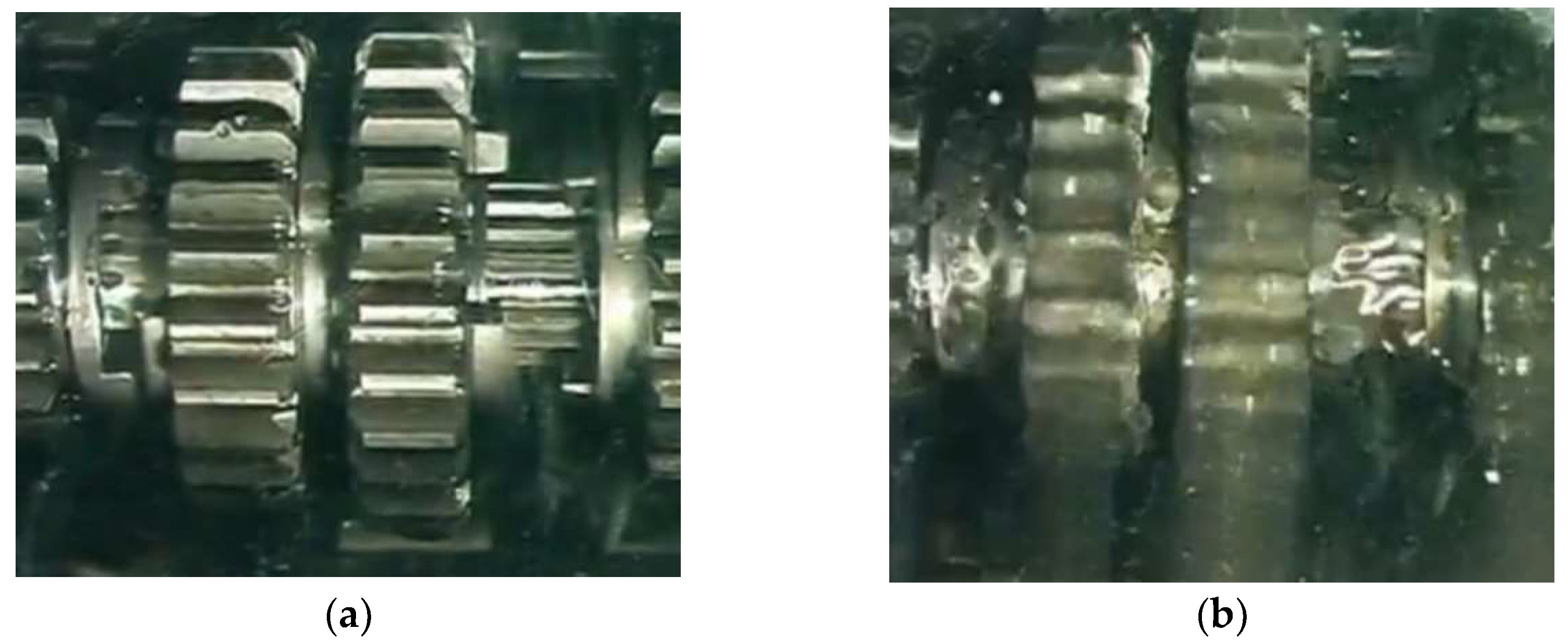
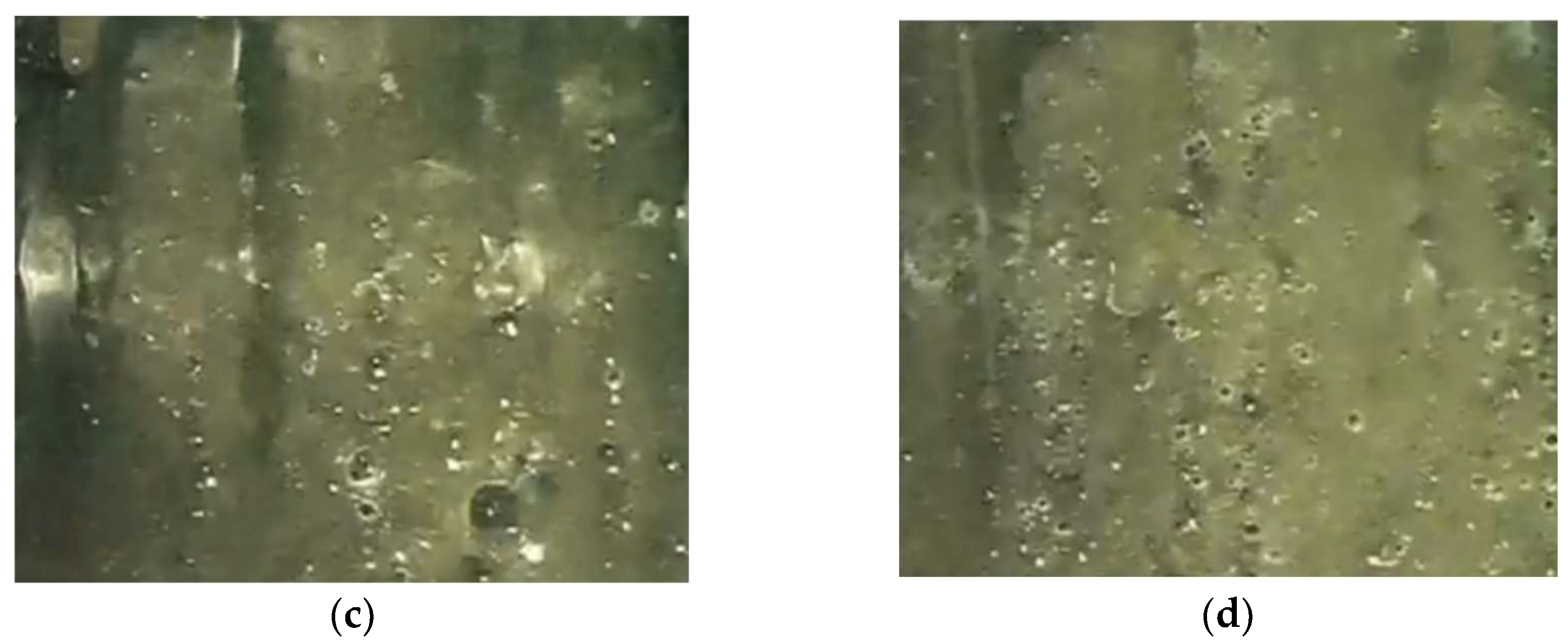
In vehicles, the peripheral speed of the gears varies over a wide range. The rotating wheels also mix air into the oil during oil circulation, and the intense foaming of this air can reduce the oil’s load capacity. An example of foaming is illustrated in a motorcycle gearbox [87], where the variation of the amount of oil applied and the state of the oil-air mixture with speed is clearly shown.
Figure 18.
Gearbox at standstill (a), at engine idle speed (n~800 rpm, (b), at 3000 rpm (c) and maximum engine speed (n~6000 rpm, (d) [88].
Figure 18.
Gearbox at standstill (a), at engine idle speed (n~800 rpm, (b), at 3000 rpm (c) and maximum engine speed (n~6000 rpm, (d) [88].
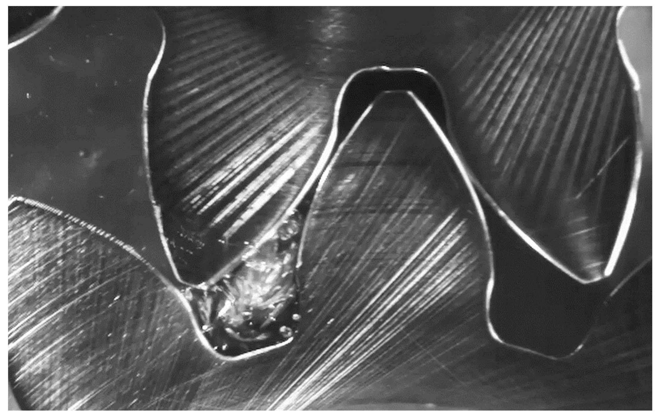
Another failure that can occur in submersible lubricated drives is cavitation, which not only damages the gear pumps.
Figure 19.
Cavitation during exit from tooth contact [89].
Figure 19.
Cavitation during exit from tooth contact [89].
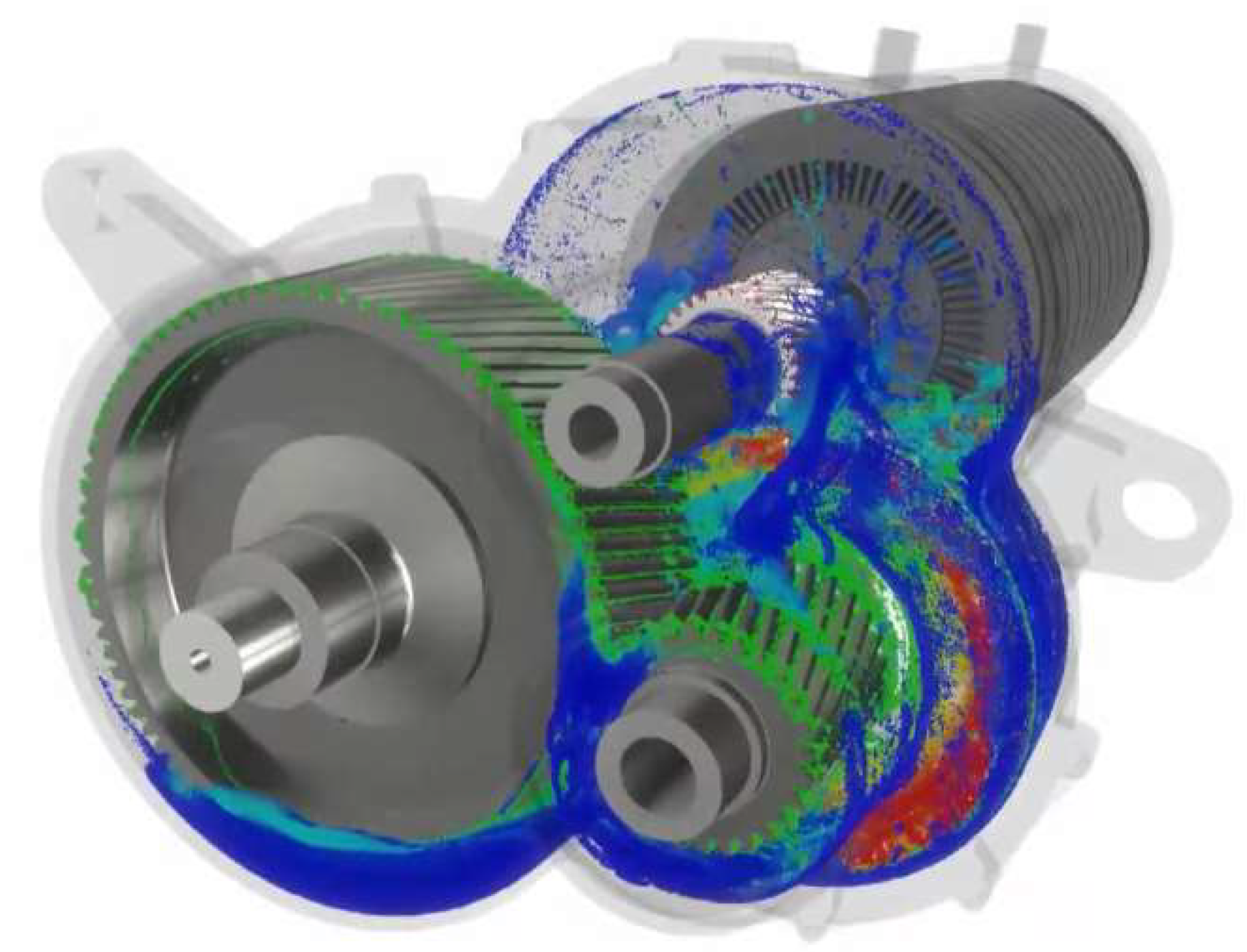
Due to the complexity of the flows in oil circulation processes and the multitude of factors that influence losses, the optimisation of gearbox lubrication is nowadays performed with advanced flow analysis software.
Figure 20.
Flow simulation of a constant ratio electric vehicle gearbox [90].
Figure 20.
Flow simulation of a constant ratio electric vehicle gearbox [90].
Windage Losses in Gearboxes
Air disturbance (windage) in high-speed gearboxes causes a loss that is essentially independent of the power transmitted, with the greatest effect on the peripheral speed of the gears, in addition to the geometry of the wheels and the viscosity of the lubricant. The lubricating oil adhering to the tooth surfaces is dispersed by centrifugal force in the form of a spray in the gearbox housing: an oil mist is formed, which is beneficial from the lubrication point of view, but increases the power loss, because the friction between the oil mist, which has a higher density than air, and the wheel body of the rotating gears can be significant.
Several researchers, including Anderson and Townsend, have developed mathematical models to describe air resistance. Anderson’s model did not take into account the geometrical characteristics of the gears, such as the gear modulus and the tooth bending angle. Townsend’s computational model is much more detailed, regarding the effect of the amount and distribution of oil mist atomized in the gearbox air space on power loss by the air-oil mixture parameter ζluft [91], and the distance between the gear body and the gearbox wall, the guard or the oil baffles by the parameter λluft.
If the air space of the planetary gear is free of oil spray, and oil mist, then:
Provided there is a free air space around the wheels:
If the gears are surrounded by oil baffles or a protective cover:
And if the gears are tightly surrounded by oil baffles or protective coverings:
According to Townsend, drag is the power loss, in watts, on the i - ed external gear:
Anderson and Loewenthal described the following relationship for calculating the power loss due to drag based on the results of disc friction tests on turbines [42]:
Seal Friction Losses
The torque loss caused by the sealing of the gearbox shafts is essentially independent of the power transmitted through the shaft. The micro- and macro-geometric structure, material properties, operating temperature, lubrication condition, and the degree of cavitation between the peaks of roughness, all influence the frictional torque loss of seals. This loss is mainly determined by the interfacial pressure and the geometry of the shaft and seal. Most of the time, elastomer seals are in contact with metallic shafts, and the exploration of their friction and wear processes is the basis of current tribological research. In addition to the complex and complicated calculations, it is also possible to determine the approximate frictional power loss of seals [38].
A simple estimation can be made using the following relation:
The following relationship gives a more precise result [16]:
The model of Marco Silvestri, Edzeario Prati and Alessandro Tasora [92] is based on visco-elastohydrodynamic (VEHD) lubrication theory, which recognizes the deformation of the sealing lip of the spring sealing ring and the pressure distribution of the lubricant film formed there.
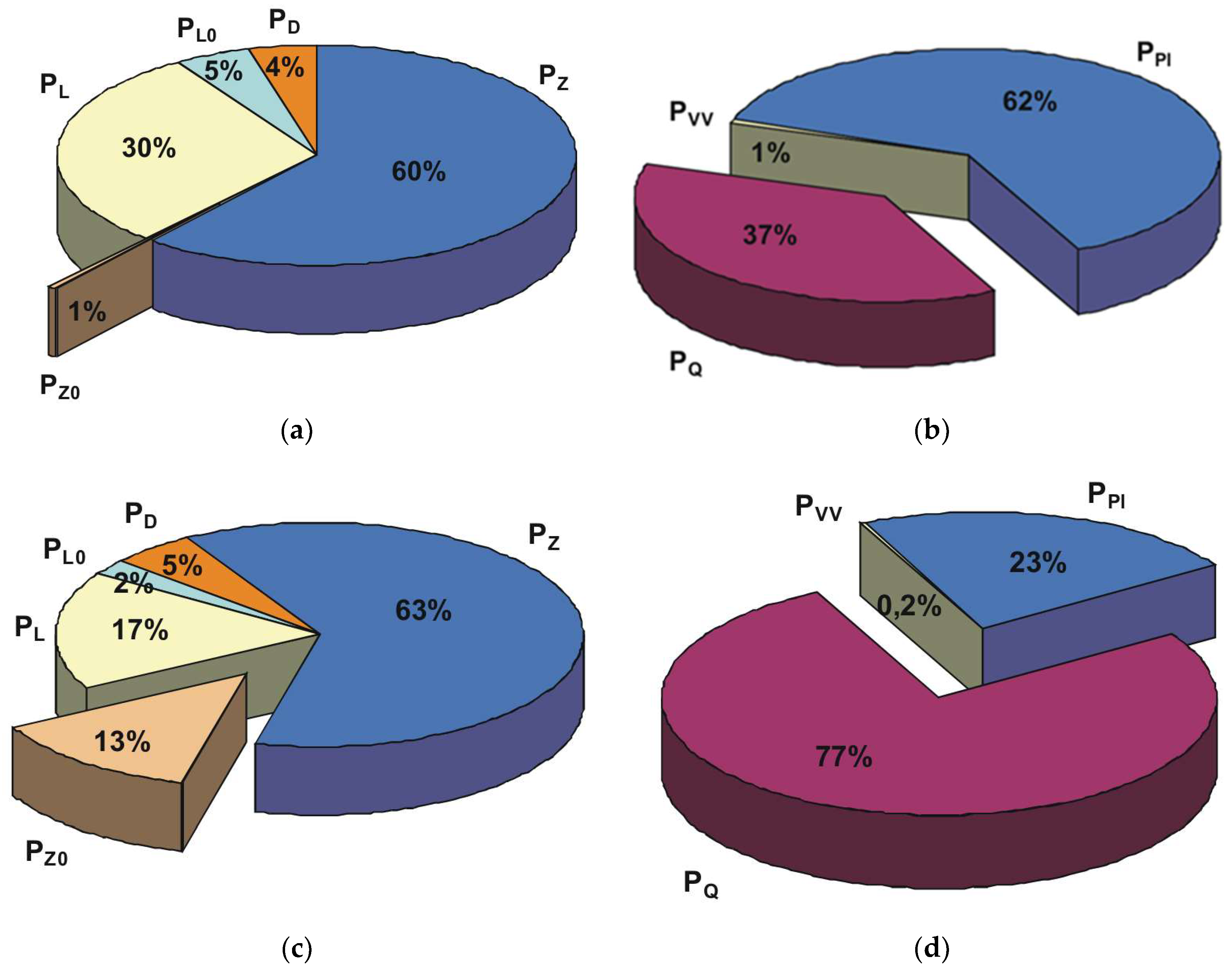
As an example, the following graphs show the power losses and their components of a properly designed and improperly designed cylindrical gear. It can be seen that significant power loss and oil swirl loss can be saved by correct design.
Figure 21.
Loss components of a single-stage, straight-gear gearbox under favorable operating conditions (a-b) and loss components of this gearbox under unfavorable operating conditions (c-d) [17]. In Figs: PL—power dependent component of bearing friction losses, PL0—power independent component of bearing friction losses, Pz—power dependent component of tooth friction losses, Pz0—power independent component of tooth friction losses, PD—seal friction losses, PQ—oil expel losses, PPl—oil churning and disc friction losses, Pvv—windage power losses.
6. Summary
The Future of Electric Powertrain Designs
In conclusion, the design of the transmissions in electric vehicles is very diverse. Improvements have been made to vehicle dynamics, to operate the engines within a high-efficiency speed range and to achieve maximum acceleration and high-top speeds. However, as the complexity of gearbox designs, system complexity and the number of components installed increases, the cost and the ecological footprint of production increases dramatically. In the future, constant ratio, geared or planetary gearboxes will likely continue to be the predominant drive system.
Based on the information processed so far, the future electric vehicle powertrains are therefore expected to be simple constructions built from common machine components. However, there are many interesting development opportunities in maximizing the load capacity and efficiency of machine elements designed using structural optimization. This is particularly necessary because the torque elasticity and dynamics of electric cars are much higher than those of conventional internal combustion engines. As a consequence, stronger machine components, bearings and gears are needed. For gears, on the other hand, the design guideline is divided according to objective functions. Noise reduction and smooth running require small tooth normal modules, high gear ratios and helical gears, while the load and torque surge rates require large modules and smaller gear ratios. Modification of the teeth is a very important design consideration. Tooth tip modification and tooth length modification play a key role in tooth surface fatigue and noise levels. Of course, there are even more interesting areas of research in this field. Macro geometric research on tooth profiles and optimization of the lubricating oil additive package are important areas. These all increase the lifetime of the lubricating oil and the efficiency of the system. However, to calculate efficiency and accurately calculate the temperature of the wheel body and oil sump, it is also necessary to know the power losses.
It is also particularly important to look at gearbox losses, including oil lubrication losses, because knowledge of the causes of these losses will allow lubrication systems to be optimized, lubricating oil additives to be determined correctly and oil life to be increased, which will also result in significant financial savings.
The direction of development is diverse, but one thing is for sure, gear drives are found in all designs, so maximizing their efficiency and designing them cost-effectively will always be a challenging engineering task.
Appendix
- Tooth Friction Losses
b—gear width [mm],
dw1—operating pitch diameter of the pinion [mm].
i—gear ratio [-],
Pin—input power [W],
PB—power loss of oil accelerating [W],
PD—power loss of seal friction [W],
Pk—oil expel power loss [W],
Pl—power dependent component of bearing friction losses [W],
Pl0—power independent component of bearing friction losses [W],
Pp—oil churning loss [W],
Pw—windage loss [W],
Px—power losses from other sources [W],
Pz—power dependent component of tooth friction losses [W],
Pz0—power independent component of tooth friction losses [W],
vcs—sliding speed between the maiting teeth [m/s],
vΣ—the lubricant inlet speed (sum of tangential speeds of the tooth profiles) [m/s],
vr—the sum of the rolling speeds [m/s],
vΣ(x)—coincidence velocity of tooth profiles along the contact line [m/s],
vtC—sum of tangential velocities at the principal point [m/s],
wt—gear tooth specific load [N/mm],
z1—tooth number of the pinion [-],
z2—tooth number of the gear [-],
βb—helix angle at the base circle [rad],
ε1; ε2—partial transverse contact ratios [-],
εα—transverse contact ratio [-],
η—dynamic viscosity of the lubricant at operating temperature [Pas],
ηM—dynamic viscosity of the lubricant at atmospheric pressure at wheel body temperature [mPas],
ηz—gear efficiency [-],
μz—coefficient of tooth friction [-],
ν;νk—kinematic viscosity of the lubrican [mm2/s],
ρne(x)—equivalent radius of curvature along the contact line [mm],
ρ—equivalent radius of curvature of the connected tooth profiles [mm].
- Oil Churning Losses
AB—the contact area of the gear body and the oil [m2],
b—gear width[mm],
bm—immersion depth of the gear [mm],
d—pitch circle of the gear [m],
Fr—Froude-number, Fr=Ω2×RP/g, where: g=9,81 m/s2,
Mch—torque loss from the oil churning [Nm],
Mpl—disc churning loss component from oil churning [Nm],
MQ1—torque loss of expel [Nm],
Re—Reynolds-number, Re=Ω×RP2/ν,
Rec—critical Reynolds-number,
r—pitch radius of the gear [m],
v—tangential speed at pitch radius [m/s],
V0—oil volume [m3],
1—index of the pinion,
2—index of the gear,
ω − angular velocity of the immersed gear [rad/s],
ν—kinematic viscosity of the lubricant [m2/s],
ρ—density of the lubricant (oil) [kg/m3].
- Windage Losses
b—gear width [m],
d—pitch circle diameter [m],
dl—feet circle diameter [mm],
mn—normal modul [mm],
n—absolut rotational speed of the gear [1/min],
ηo—dynamic viscosity of the lubricant [Ns/m2].
- Seal Friction Losses
dt—shaft diameter [mm],
Mr—friction torque [Nm],
nt—absolut rotational speed of the shaft [1/min],
Pi—pressure under the seal lip [N/m],
Psl—power loss [W],
ts—oil temperature [°C],
ν40—kinematic viscosity of the lubricant at 40 [°C] temperature [mm2/s].
References
- M. Pisaturo and A. Senatore, ‘Simulation of engagement control in automotive dry-clutch and temperature field analysis through finite element model’, Appl. Therm. Eng., vol. 93, pp. 958–966, Jan. 2016. [CrossRef]
- ‘Home | GKN Automotive’. . Available online: https://www.gknautomotive.com/. (accessed on 20 December 2024).
- ‘AVL Home | AVL’. . Available online: https://www.avl.com/en. (accessed on 20 December 2024).
- ‘Home’, Electronic Design. . Available online: https://www.electronicdesign.com/. (accessed on 20 December 2024).
- ‘Ann Arbor Import Auto Repair & Service | European, Asian & Domestic Repairs’. . Available online: https://www.arbormotion.com/. (accessed on 20 December 2024).
- ‘PriusChat’, PriusChat. . Available online: https://priuschat.com/forum/. (accessed on 20 December 2024).
- ‘Schaeffler active eDifferential: The active differential for future drive trains: Schaeffler Symposium’, 2010. . Available online: https://www.semanticscholar.org/paper/Schaeffler-active-eDifferential%3A-The-active-for/bf7cb351b5f0e1f183913398111e84956f0e0b9d. (accessed on 20 December 2024).
- ‘Automated manual transmissions | Fuller transmission’, Eaton. . Available online: https://www.eaton.com/us/en-us/products/transmissions.html. (accessed on 20 December 2024).
- M. Vajedi and N. L. Azad, ‘Ecological Adaptive Cruise Controller for Plug-In Hybrid Electric Vehicles Using Nonlinear Model Predictive Control’, IEEE Trans. Intell. Transp. Syst., vol. 17, no. 1, pp. 113–122, 2016. [CrossRef]
- S. M. Group, ‘Home - Mobility Engineering Technology’. . Available online: https://www.mobilityengineeringtech.com/. (accessed on 20 December 2024).
- ‘Charged EVs’, Charged EVs. . Available online: https://chargedevs.com/. (accessed on 20 December 2024).
- ‘openPR.com - Worldwide Open Public Relations - Publish Press Releases Free of Charge’. . Available online: https://www.openpr.com/. (accessed on 20 December 2024).
- Csobán, ‘Bolygóművek hő-teherbírásának meghatározása, Ph.D. doktori értekezés’, Budapest: Budapesti Műszaki és Gazdaság-tudományi Egyetem, 2011.
- ‘BPW eTransport electric drive axle’, Mynewsdesk. . Available online: https://newsroom-en.bpw.de/images/bpw-etransport-electric-drive-axle-1429834. (accessed on 20 December 2024).
- ‘ZF AVE 130’. . Available online: https://press.zf.com/press/en/media/media_1506.html. (accessed on 20 December 2024).
- Y. N. Drozdov and Y. A. Gavrikov, ‘Friction and scoring under the conditions of Simultaneous rolling and sliding of bodies’, Wear, vol. 11, no. 4, pp. 291–302, Apr. 1968. [CrossRef]
- D. Strasser, ‘Einfluss des Zahnflanken- und Zahnkopfspieles auf die Leerlaufverlustleistung von Zahnradgetrieben’, Ruhr-Universität Bochum: Fakultät für Maschinenbau, 2005.
- Z. Terplán, F. Z. Terplán, F. Apró, and Á. Döbröczöni, Fogaskerék-bolygóművek. Budapest: Műszaki Könyvkiadó, 1979.
- G. Niemann and H. Winter, Maschinenelemente, vol. 1–3. Springer Verlag, 1989. Accessed: Dec. 17, 2024. Available online: https://www.springer.com/series/0421.
- M. Duda, ‘Der geometrische Verlustbeiwert und die Verlustunsymmetrie bei geradverzahnten Stirnradgetrieben’. Forschung im Ingenieurwesen 37 VDI-Verlag, 1971.
- H. Klein, Bolygókerék hajtóművek. Budapest: Műszaki Könyvkiadó, 1968.
- J. P. O’Donoghue and A. Cameron, ‘Friction and Temperature in Rolling Sliding Contacts’, E Trans., vol. 9, no. 2, pp. 186–194, Jan. 1966. [CrossRef]
- Y. A. Misharin, ‘Influence of The Friction Condition on The Magnitude of The Friction Coefficient in The Case of Rollers with Sliding’, Proc Int Conf Gearing, pp. 159–164, 1958.
- ‘ISO/TR 13989-1:2000(en), Calculation of scuffing load capacity of cylindrical, bevel and hypoid gears — Part 1: Flash temperature method’. Accessed: Dec. 17, 2024. Available online: https://www.iso.org/obp/ui/es/#iso:std:iso:tr:13989:-1:ed-1:v1:en.
- G. H. Benedict and B. W. Kelly, ‘Instanteous Coefficients of Gear Tooth Friction’, in Transactions of ASLE, 1960, pp. 55–70.
- H. Xu, ‘Development of a generalized mechanical efficiency prediction methodology for gear pairs’, The Ohio State University, 2005. Accessed: Dec. 17, 2024. Available online: https://etd.ohiolink.edu/acprod/odb_etd/etd/r/1501/10?clear=10&p10_accession_num=osu1128372109.
- E. Ciulli, I. E. Ciulli, I. Bartilotta, and A. Polacco, ‘A Model for Scuffing Prediction’, Journal of Mechanical Engineering. Accessed: Dec. 17, 2024. Available online: https://www.sv-jme.eu/article/a-model-for-scuffing-prediction/.
- F. Reuleaux, ‘Friction in Tooth Gearing’, Trans. ASME, vol. VIII, no. 9, pp. 45–85, 1886.
- K. F. Martin, ‘A review of friction predictions in gear teeth’, Wear, vol. 49, no. 2, pp. 201–238, Aug. 1978. [CrossRef]
- T. Yada, ‘Review of Gear Efficiency Equation and Force Treatment’, JSME Int. J. Ser C Dyn. Control Robot. Des. Manuf., vol. 40, no. 1, pp. 1–8, 1997. [CrossRef]
- Y. Li and A. A. Seireg, ‘Predicting The Coefficient of Friction in Sliding-Rolling Contacts’, Tribol. Conf., no. K18.
- C. Naruse, S. C. Naruse, S. Haizuka, R. Nemoto, and H. Takahashi, ‘Influences of Tooth Profile on Frictional Loss and Scoring Strength in The Case of Spur Gears’, MPT’91 JSME Int’l Conf. Motion Power Transm. Hiroshima Jpn., 1991.
- H. Mizutani and Y. Isikawa, ‘Power Loss of Long Addendum Spur Gears’, VDI Berichte, vol. 1230, pp. 83–95, 1996.
- T. Yada, ‘The Measurement of Gear Mesh Friction Losses’, ASME 72-PTG-35, Oct. 1972.
- C. Changenet and M. Pasquier, ‘Power Losses and Heat Exchange in Reduction Gears: Numerical and Experimental Results’, VDI Berichte, vol. 1665, pp. 603–613, 2022.
- K. Ikejo and K. Nagamura, ‘Power Loss of Spur Gear Drive Lubricated with Traction Oil’, presented at the DETC’03/PTG, Chicago, Illinois, 2003.
- F. Hirano and T. Ueno, ‘EFFECT OF ANGLE BETWEEN DIRECTION OF SLIDING+ LINE OF CONTACT ON FRICTION+ WEAR OF ROLLER’, Lubr. Eng., vol. 20, no. 2, p. 57, 1964.
- C. M. Denny, ‘Mesh Friction in Gearing’, AGMA Fall Tech. Meet., vol. 98FTM2, 1998.
- J. I. Pedrero, ‘Determination of The Efficiency of Cylindrical Gear Sets’, 4th World Congr. Gearing Power Transm. Paris Fr., Mar. 1999.
- Y. Michlin and V. Myunster, ‘Determination of power losses in gear transmissions with rolling and sliding friction incorporated’, Mech. Mach. Theory, vol. 37, no. 2, pp. 167–174, Feb. 2002. [CrossRef]
- N. E. Anderson and S. H. Loewenthal, ‘Efficiency of Nonstandard and High Contact Ratio Involute Spur Gears’, J. Mech. Transm. Autom. Des., vol. 108, no. 1, pp. 119–126, Mar. 1986. [CrossRef]
- N. E. Anderson and S. H. Loewenthal, ‘Design of Spur Gears for Improved Efficiency’, J. Mech. Des., vol. 104, no. 4, pp. 767–774, Oct. 1982. [CrossRef]
- N. E. Anderson and S. H. Loewenthal, ‘Effect of Geometry and Operating Conditions on Spur Gear System Power Loss’, J. Mech. Des., vol. 103, no. 1, pp. 151–159, Jan. 1981. [CrossRef]
- J. P. Barnes, ‘Non-Dimensional Characterization of Gear Geometry, Mesh Loss and Windage’, 97FTM11, 1997.
- M. Vaishya and D. R. Houser, ‘Modeling and Measurement of Sliding Friction for Gear Analysis’, 99FTMS1, Oct. 1999.
- D. Dowson and G. R. Higginson, ‘A theory of involute gear lubrication’, Proceeding Symp. Organ. Mech. Tests Lubr. Panel Inst. Inst. Pet. Gear Lubr., vol. 182, no. 1, pp. 8–15.
- K. F. Martin, ‘The Efficiency of Involute Spur Gears’, J. Mech. Des., vol. 103, no. 1, pp. 160–169, Jan. 1981. [CrossRef]
- Y. Wang, H. Y. Wang, H. Li, J. Tong, and J. Jang, ‘Transient thermoelastohydrodynamic lubrication analysis of an involute spur gear | Request PDF’, ResearchGate, Oct. 2024. [CrossRef]
- S. Wu and H. S. Cheng, ‘A Friction Model of Partial-EHL Contacts and its Application to Power Loss in Spur Gears’, ResearchGate, Oct. 2024. [CrossRef]
- P. H. Dawson, ‘High-speed Gear Windage’, GEC Rev., vol. 4, no. 3, pp. 164–167, 1988.
- P. Luke and A. V. Olver, ‘A study of churning losses in dip-lubricated spur gears’, Proc. Inst. Mech. Eng. Part G J. Aerosp. Eng., vol. 213, no. 5, pp. 337–346, May 1999. [CrossRef]
- Y. Diab, F. Y. Diab, F. Ville, P. Velex, and C. Changenet, ‘Windage Losses in High Speed Gears—Preliminary Experimental and Theoretical Results’, J. Mech. Des., vol. 126, no. 5, pp. 903–908, Oct. 2004. [CrossRef]
- D. Dowson and G. R. Higginson, Elasto-hydrodynamic lubrication | WorldCat.org. Pergamon Press, Oxfort, 1977. Accessed: Dec. 17, 2024. Available online: https://search.worldcat.org/title/569568722.
- S. Ali, ‘DUDLEY's HANDBOOK OF PRACTICAL GEAR DESIGN and MANUFACTURE’, Accessed: Dec. 17, 2024. Available online: https://www.academia.edu/45138343/DUDLEYs_HANDBOOK_OF_PRACTICAL_GEAR_DESIGN_and_MANUFACTURE.
- P. Heingartner and D. Mba, ‘Determining Power Losses in The Helical Gear Mesh; Case Study, Chicago, Illinois, 2003’, presented at the DETC’3, Chicago, Illinois, 2003.
- R. Stribeck, Kugellager für beliebige Belastungen. Springer, 1901.
- Palmgren, Neue Untersuchungen über Energieverluste in Wälzlagern | WorldCat.org. SKF Kugellagerfabriken, Schweinfurt, 1975. Accessed: Dec. 17, 2024. Available online: https://search.worldcat.org/title/313978755.
- T. Bartels, ‘Instationäres Gleitwälzkontaktmodell zur Simulation der Reibung und Kinematik von Rollenlagern’, Ruhr-Universität Bochum, 1997.
- T. Bartels, ‘Bordreibung von Zylinderrollenlagern’, in Antrienbtechnik, vol. 420, 1994.
- P. Eschmann, ‘Einleitung’, in Das Leistungsvermögen der Wälzlager: Eine Beurteilung nach neuen Gesichtspunkten, P. Eschmann, Ed., Berlin, Heidelberg: Springer, 1964, pp. 1–3. [CrossRef]
- P. K. Gupta, Advanced Dynamics of Rolling Elements. New York, NY: Springer, 1984. [CrossRef]
- G. Hansberg, ‘Fresstragfähigkeit vollrolliger Planetenrad-Wälzlager’, Ruhr-Universität Bochum, 1991.
- J. Hollatz, ‘Start– und Reibungsverhalten von ölgeschmierten Wälzlagern bei Umgebungstemperaturen bis – 40 °C’, Universität Hannover, 1984.
- J. Koryciak, ‘Einfluss der Ölmenge auf das Reibmoment von Wälzlagern mit Linienberühnung’, Ruhr-Universität Bochum, 2007.
- H. Korrenn, ‘The Axial Load-Carrying Capacity of Radial Cylindrical Roller Bearings’, J. Lubr. Technol., vol. 92, no. 1, pp. 129–134, Jan. 1970. [CrossRef]
- B. Liang, ‘Berechnungsgleichungen für Reibmomente in Planetenrad-Wälzlagern’, Ruhr-Universität Bochum, 1992.
- Potthoff, ‘Anwendungsgrenzen vollrolliger Planetenrad-Wälzlager’, Ruhr-Universität Bochum, 1986.
- B. Scherb, ‘Prediction and Measurement of Friction Torque Characteristics of Radially and Axially Loaded Readial Cylindrical Roller Bearings’, University of Glamorgan, UK, 1999.
- T. Siepmann, ‘Reibmomente in Zylinderrollenlagern für Planetenrädern’, Ruhr-Universität Bochum, 1987.
- H. Kumar and V. Gupta, ‘Effect of Surface Roughness on the Friction Moment in a Lubricated Deep Groove Ball Bearing’, Accessed: Dec. 28, 2024. Available online: https://www.mdpi.com/2075-4442/12/12/443.
- P. Lee, C. P. Lee, C. Sanchez, M. Moneer, and A. Velasquez, ‘Electrification of a Mini Traction Machine and Initial Test Results’, Lubricants, vol. 12, no. 10, p. 337, Sep. 2024. [CrossRef]
- Y. Ariura, ‘The Lubricant Churning Loss and its Behaviour in Gear Box in Cylindrical Gear Systems’, J. Jpn. Soc. Lubr. Eng., vol. 20, no. 3, 1975, . Available online: https://scholar.google.com/scholar_lookup?&title=The%20lubricant%20churning%20loss%20and%20its%20behavior%20in%20gearbox%20in%20cylindical%20gear%20systems&publication_year=1975&author=Ariura%2CY&author=Ueno%2CT#d=gs_cit&t=1734713379861&u=%2Fscholar%3Fq%3Dinfo%3AkmcULDnzRXEJ%3Ascholar.google. (accessed on 20 December 2024).
- Y. Ariura, T. Y. Ariura, T. Ueno, T. Sunaga, and S. Sunamoto, ‘The Lubricant Churning Loss in Spur Gear Systems’, Bull. JSME, vol. 16, no. 95, pp. 881–892, 1973. [CrossRef]
- P. Walter, ‘Untersuchungen zur Tauchschmierung von Stirnrädern bei Umfangsgeschwindigkeiten bis 60 m/s’, Universität Stuttgart, 1982.
- W. Mauz, Hydraulische Verluste bei Tauch- und Einspritzschmierung von Zahnradgetrieben: Abschlußbericht ; Forschungsvorhaben Nr. 44/III ; Berichtszeitraum: 1983-1984. FVA, 1985.
- S. Terekhov, ‘Hydraulic losses in gearboxes with oil immersion’, Russ. Eng. J., vol. 55, 1975.
- S. Terekhov, ‘Basic Problems of Heat Calculation of Gear Reducers’, JSME Int. Conf. Motion Powertransmissions, 1991.
- J. Maurer, ‘Lastunabhängige Verzahnungsverluste schnellaufender Stirnradgetriebe’, in Dissertation Universität Stuttgart, Stuttgart, 1994.
- Dick, ‘Untersuchungen zu den Leerlaufverlusten eines einspritzgeschmierten Stirnradgetriebes’, in Dissertation Universität Stuttgart, 1989.
- Sax, ‘Untersuchungen zur Wirkungsweise der Tauchschmierung’, in Dissertation Universität Stuttgart, 1996.
- Schimpf, ‘Untersuchungen zur Wirkungsweise der Tauchschmierung’, in Dissertation Universität Stuttgart, 1994.
- D.-O. Leimann, ‘Wärmearm konstruieren, Teil 1: Einfluss des Zahnflankenspiels auf die Erwärmung bzw. Verlustleistung von Zahnradgetrieben’, in Antriebstechnik, vol. 3, in 32, vol. 3., 1993, pp. 70–73.
- D.-O. Leimann, ‘Einfluss der Übersetzungsaufteilung auf die Erwärmung von Zahnradgetrieben’, in Wärmearm konstruieren, vol. 5, in Antriebstechnik 32, vol. 5., 1993, pp. 85–883.
- E. Lauster, ‘Untersuchungen und Berechnungen zum Wärmehaushalt mechanischer Schaltgetriebe’, Dissertation Universität Stuttgart, 1980.
- M. Butsch, ‘Hydraulische Verluste schnelllaufender Stirnradgetriebe’, in Dissertation Universität Stuttgart, 1989.
- J. Tochtermann, ‘Development of an integrated axle for MD trucks for urban distribution traffic’, presented at the 16th International CTI Symposium Automotive Transmissions, HEV and EV Drives, Berlin, 2017.
- ‘Edison Motors’, Edison Motors. . Available online: https://www.edisonmotors.ca. (accessed on 20 December 2024).
- kmx888, Royal Enfield UCE Gearbox Lubrication, (Sep. 01, 2009). Accessed: Dec. 28, 2024. [Online Video]. Available: https://www.youtube.com/watch?v=2V_rP88YEP0.
- FPRG, External Gear Pump - Cavitation, (Apr. 27, 2017). Accessed: Dec. 28, 2024. [Online Video]. Available: https://www.youtube.com/watch?v=a_o0v9mPkhU.
- TECHNIA Simulation, SIMULIA XFlow: Simulation of gearbox Lubrication, (May 22, 2019). Accessed: Dec. 28, 2024. [Online Video]. Available: https://www.youtube.com/watch?v=irb2V2-JO2w.
- ‘Automotive News | Car News | AutoNews.com’. . Available online: https://www.autonews.com/. (accessed on 20 December 2024).
- M. Silvestri, ‘A Theoretical Study of Viscoelastohydrodinamic Lubrication (VEHL) in Elastomeric Lip Seals’, presented at the ECOTRIB 2009, Pisa, Italy, 2009.
Disclaimer/Publisher’s Note: The statements, opinions and data contained in all publications are solely those of the individual author(s) and contributor(s) and not of MDPI and/or the editor(s). MDPI and/or the editor(s) disclaim responsibility for any injury to people or property resulting from any ideas, methods, instructions or products referred to in the content. |
© 2025 by the authors. Licensee MDPI, Basel, Switzerland. This article is an open access article distributed under the terms and conditions of the Creative Commons Attribution (CC BY) license (https://creativecommons.org/licenses/by/4.0/).
Copyright: This open access article is published under a Creative Commons CC BY 4.0 license, which permit the free download, distribution, and reuse, provided that the author and preprint are cited in any reuse.


