Submitted:
27 December 2024
Posted:
27 December 2024
You are already at the latest version
Abstract
Taking the detection device of the lifting lighting system on fire fighting vehicles as the research object, the structure optimization design of the detection device was carried out to address the problems of the illuminance meter currently used for current detection of fire fighting vehicles, such as the need for testing in large open areas and poor environmental adaptability. A set of integrated detection devices for the "angle & illuminance" of the lifting lighting system on fire fighting vehicles was obtained. The main body of the device consists of three parts: "angle de-tection device", "illuminance detection device ", and "angle & illuminance data integration ter-minal". It can achieve synchronous detection and real-time monitoring of the angle and illumi-nance of the lighting system. The results show that the optimized detection device of the lighting system can detect the illumination of the lifting lighting system on fire fighting vehicles in small areas on long and narrow road sections. The angle detection accuracy is 0.1 °, and the illuminance detection accuracy is 0.1 lx, with an error of less than 3 % compared to the illuminance meters currently used for detection. The illumination detection device has the function of automatic leveling, ensuring that the device can smoothly complete the detection work even when placed on uneven road surfaces.
Keywords:
fire fighting vehicle
; lifting lighting system
; integrated
; detection device
1. Introduction
As fire-fighting and rescue equipment, commonly used lighting fire fighting vehicles, rescue fire fighting vehicles, even some foam fire fighting vehicles and compressed air foam system fire fighting vehicles are equipped with lifting lighting systems, whose lighting capacity directly affects the rescue efficiency. According to preliminary research, as of the end of 2023, there were approximately 56000 fire fighting vehicles in use by national firefighting and rescue teams of China, 20000 fire fighting vehicles in use in industries such as petroleum, petrochemical, electric power, and civil aviation. Above all, nearly 80000 fire fighting vehicles in use nationwide. Among them, the number of fire fighting vehicles with lifting lighting systems exceeded 15000, accounting for approximately 18.75% of all. In recent years, the annual purchase volume of fire fighting vehicles for Chinese firefighting and rescue teams is about 4000, and 1000 for other industries. Among them, there are more than 1200 fighting vehicles with lifting lighting systems, accounting for about 24%.
In the field of measuring illuminance, domestic and foreign experts and scholars have achieved many research results.
In the research of illuminance meters, Weng J J developed a simple illuminance meter with good system linearity and accuracy based on the design and construction of photoelectric signal amplification circuits [1]. Luo Z Y introduced the design principle and implementation method of a multi-channel illuminometer for signal detection [2]. Luo Y P has developed a portable illuminance meter suitable for industrial and outdoor illuminance measurement scenarios [3]. Zhang Y J proposed a method for measuring illuminance based on camera images, which can achieve fast and high-precision measurement of environmental illuminance in images [4]. The study by Králiková R mentioned an illuminometer called RadioLux 111, mainly used for measuring illuminance in the absence of sunlight [5]. Lebel P introduced the design and application of a handheld luminometer powered by battery and produced in the United States [6].
In the research of calibration of illuminance meters, Godo K found that the calibration of illuminance meters largely depends on the measurement distance and their own structure [7]. Kuvaldin E V investigated the main issues in the development, manufacture and calibration of high-sensitivity illuminance meters [8]. On the basis of studying conventional illuminance meters, Tabaka P provided 22 different typical spectral sensitivity curves [9].
In the research of illuminance detection systems, Zhang L Q developed a distributed illuminance detection device with functions such as illuminance measurement, data transmission and storage [10]. Vochozka V studied the use of laboratory equipments and mobile phones with installed applications to measure illuminance, and further explored the reliability of data collection on mobile phones [11]. Lorenzo O G designed and deployed a platform based on the technology of Internet of Things (IoT) to collect illumination data and store it centrally [12].
In the research of illuminance detection methods, Xie W K conducted indoor illuminance measurements under natural and artificial lighting conditions, and analyzed the methods of illuminance measurement and evaluation of lighting environment [13]. Gou L conducted a study on lighting measurement methods for highway tunnels in Shanxi due to their low brightness, high smoke and dust levels [14]. Wang Z B used classroom lighting detection as an example to study the illuminance testing methods and summarized the tips in the process of illuminance measurement [15].
On the basis of referring to the above research results, this paper conducted a study on the integrated detection device for the “angle & illuminance” of the lifting lighting system on fire fighting vehicles. In response to the high requirements of the testing site for the illumination detection of fire fighting vehicles, equivalent conversion was adopted to optimize the detection method, in order to develop a corresponding complete set of detection devices, and the accuracy of illumination detection was verified through comparative experiments.
2. Analysis of Detection Methods
2.1. Analysis of Test Methods in Current Chinese Standards of Fire Fighting Vehicles
At present, the illuminance of the lifting lighting system on fire fighting vehicles in China needs to meet the requirements of relevant clauses in “GB 7956.16 - 2019 Fire fighting vehicles - Part 16: Lighting fire fighting vehicle” [16] and “GB 7956.14 - 2015 Fire fighting vehicles - Part 14: Rescue fire fighting vehicle” [17]. The standards specify the test requirements for illuminance. In addition to the environmental illuminance not exceeding 0.1 lx during testing, the size requirements for the site are also very high.
2.1.1. Lighting Fire Fighting Vehicle
In the standard for lighting fire fighting vehicles, it is stipulated that the illuminance of each test point of the main lighting lamp should not be less than 5 lx within the range from 30 m to 100 m, as shown in Figure 1a. And the illuminance of each test point of the auxiliary lighting lamp within the range from 10 m to 30 m should not be less than 5 lx, as shown in Figure 1b. When measuring illuminance, take the origin “O” as the position of the lifting lighting system on the fire fighting vehicle, raise the lighting lamp to the highest position and adjust the angle to make its illumination direction horizontal. Test within the angle range from −35 ° to +35 ° with the illumination direction at 0 °. The test points are all the intersection points of the arc and the ray in the figure.
2.1.2. Rescue Fire Fighting Vehicle
In the standard for rescue fire fighting vehicles, it is stipulated that the illuminance of each test point within a 50 m range of the lighting system should not be less than 5 lx, as shown in Figure 2. When measuring illuminance, take the origin “O” as the position of the lifting lighting system on the fire fighting vehicle, raise the lighting lamp to the highest position and adjust the angle to make its illumination direction horizontal. Test within the angle range from 0 ° to 35 ° with the illumination direction at 0 °. The test points are all the intersection points of the arc and the ray in the figure.
2.2. Difficulty Analysis of Experimental Conditions
According to the test requirements in the standards, the detection of lifting lighting systems for lighting fire fighting vehicles requires an open flat or cement ground with a radius of 100 m and a center angle of 70 °. So the area is approximately 6106 m2. Relatively, the detection of lifting lighting systems for rescue fire fighting vehicles require an open flat or cement ground with a radius of 50 m and a center angle of 35 °, with an area of approximately 764 m2.
During the inspection and testing process of “acceptance of fire fighting vehicles”, “safety testing and evaluation of fire fighting vehicles in use”, “retirement and scrap of fire fighting vehicles” and “annual inspection of fire fighting vehicles” for Chinese firefighting and rescue teams, significant difficulties were found in detecting the illumination of the lifting lighting systems. After consideration, there are three reasons: Firstly, each detachment does not have sufficient open flat or cement ground for testing, and the vehicles need to be driven to other nearby places that meet the requirements of the testing site for testing. However, due to the strict site selection requirements, the testing period is extended. Secondly, the fire fighting vehicles are in a 24-hour standby state, making them inconvenient to move. Finally, part of fire fighting vehicles may need to be retired or scrapped have not yet been evaluated for their driving safety, which could pose risks on the road. And hauling them will also impose a significant financial burden on the detachment. If maintenance is required after evaluation, the maintenance cycle will be long, which will cause inconvenience to the testing work.
Therefore, it is necessary to solve the problem of inspection site and improve inspection efficiency through equivalent conversion of experimental methods and optimization of detection devices.
3. Scheme Design and Device Development
3.1. Equivalent Conversion of Experimental Methods
Taking the lighting fire fighting vehicle as an example, according to the requirements of the standard, when testing the lifting lighting system, it is necessary to fix the lighting lamp and place the illuminance meter at various measuring points within the standard site for testing, as shown in Figure 3a. In order to reduce the area requirement of the site, the position of the illuminance detection device can be fixed through equivalent conversion, and the illuminance can be tested by circumferentially rotating the lighting lamp from −35 ° to +35 °, as shown in Figure 3b. During the rotation process, the angle detection device can be used to determine the rotation angle of the lighting lamp.
3.2. Scheme Design
According to the equivalent conversion concept mentioned earlier, a complete design of an integrated detection device for the “angle & illuminance” was proposed, which includes three parts: “angle detection device”, “illuminance detection device”, and “ angle & illuminance data integration terminal”. As shown in Figure 4, before testing, fix the angle detection device on the pan tilt of the lifting lighting system, align the illuminance detection device with the direction of illumination of the lighting lamp, and place it at a distance that meets the standard requirements from the lifting lamp pole. Then connect the data integration terminal wirelessly to the two detection devices. After turning on the lighting, the current illuminance value can be displayed on the terminal in real-time. By rotating the lighting lamp in a circumferential direction, the current angle value can also be displayed in real-time on it.
The model design of the angle detection device is shown in Figure 5, with a built-in angle sensor. When in use, it needs to be horizontally placed on the top pan tilt of the lifting lighting system, and the rope hook of the ratchet tensioner should be threaded through the metal pull rings on both sides of the device, tied together with the pan tilt, to achieve rotation angle detection during the lighting rotation process.
The model design of the illuminance detection device is shown in Figure 6. A dust cap is installed to protect the illuminance sensor at the top, which needs to be removed during use. The bottom is equipped with an automatic leveling component, which needs to be leveled before detection to ensure that the illuminance sensor is in accordance with the standard requirement of “the photosensitive surface is perpendicular to the ground and facing upwards [16,17]”, used for illuminance detection.
Both detection devices are embedded with wireless transceivers, which can be directly connected to the software on the data integration terminal. The software interface is shown in Figure 7. The connection status of two detection devices will be displayed in the upper left corner, with green indicating a successful connection signal. The main interface displays a coordinate system with the horizontal axis as the angle and the vertical axis as the illuminance. The received angle and illuminance data will be plotted as a curve in real-time. As the illuminance value at the test point required by the standard is not less than 5 lx, the 5 lx in the interface will be marked with a whole red horizontal line to facilitate intuitive observation of the data points that do not meet the standard requirements. The lower area displays the “current angle value”, “current illuminance value”, “maximum illuminance value”, “minimum illuminance value”, and “average illuminance value” in real-time. At the same time, according to the practical needs of fire rescue, an additional item “angle difference with continuous illuminance greater than 5 lx” has been added to calculate the extent which the illuminance within the 360 ° circumferential range of the lighting lamp is greater than 5 lx when fixed in a certain direction. And it also provides data support for future standard revision. The bottom area is equipped with “START”, “STOP” and “DATA SAVE” buttons to facilitate the collection and storage of data during the detection process. In addition, the “CALIBRATION” button is set for the calibration of the illumination detection device, and the “RETURN” button is used to return to the initial interface of the software.
3.3. Device Development
In response to the scheme mentioned earlier, a complete set of integrated detection devices for the angle illuminance of the lifting lighting system on fire fighting vehicles has been developed. The finished product is shown in Figure 8, which includes the angle detection device, ratchet tensioner, illuminance detection device, data integration terminal and the toolbox for them. The integrated detection device is suitable for environmental temperature ranging from −20 ℃ to +55 ℃, with a sampling frequency of 10 Hz. The angle testing accuracy is 0.1 °, the illumination testing accuracy is 0.1 lx, and the maximum working time of the built-in battery is 12 h. The total weight of the device is less than 10 kg, that making it easy to carry.
4. Experimentation
In order to verify the effectiveness of equivalent conversion of the experimental method, the practicality of the entire detection device and the accuracy of illumination detection, a comparison test was conducted between the measured/calibrated detection device and the portable illuminance meters A and B used in the current Chinese fire fighting vehicle detection process, as shown in Figure 9a,b. The test samples were a certain lighting fire fighting vehicle and a certain rescue fire fighting vehicle, and the test data were recorded in Table 1 and Table 2.
After calculation, the newly developed detection device measured the illuminance value of the lighting lamp on the lighting fire fighting vehicle at a distance of 100 m, which is different from the data measured by illuminance meters A and B only at one test point, with a difference of 1.56%. And the illuminance value measured by the auxiliary lighting lamp at a distance of 30 m differs from the illuminance meter A by an average of 2.78%, and from the illuminance meter B by an average of 1.77%. The illuminance value measured by the rescue fire fighting vehicle at a distance of 50 m is different from the value of only one test point on illuminance meter A, with a difference of 2.13%, which is the same as the data on illuminance meter B. The data above also indicates that the illumination detection accuracy of the entire developed device is relatively high.
5. Conclusions
This paper focuses on the illumination detection problem of the lifting lighting system on fire fighting vehicles discovered during the “acceptance of fire fighting vehicles”, “safety testing and evaluation of fire fighting vehicles in use”, “retirement and scrap of fire fighting vehicles” and “annual inspection of fire fighting vehicles” for Chinese firefighting and rescue teams. As the teams do not have testing sites that meet the standard size requirements, equivalent conversion of illumination detection methods was studied. And an integrated detection device for the “angle & illuminance” has been developed, which has the following advantages or functions:
(1) Great environmental adaptability. The illumination detection of the lifting lighting system on fire fighting vehicles can be carried out in small areas with long and narrow road sections, and the illumination detection device has an automatic leveling function, which can smoothly complete the detection work even when placed on uneven road surfaces.
(2) High detection accuracy. The angle testing accuracy is 0.1 °, the illuminance testing accuracy is 0.1 lx, and the illuminance values measured in the comparative experiment differed by up to 0.2 lx from the two high-precision illuminance meters currently used for illuminance detection of fire fighting vehicles, and both within 3%.
(3) Convenient data processing. The data integration terminal can wirelessly connect angle and illuminance detection devices, then record the measured data in real-time, draw the “angle & illuminance” curve, and save the data.
(4) Has expandable functionality. By rotating the lighting lamp once, the angle range that meets the illumination requirement of more than 5 lx can be measured, providing data support for the future revision of relevant standards.
Author Contributions
Conceptualization, M.X. and Y.Z. (Yi Zhu); methodology, M.X. and Y.Z. (Yi Zhu); software, Y.Z. (Yun Zhu) and C.W.; validation, M.X., Y.Z. (Yi Zhu) and J.Y.; formal analysis, M.X. and B.L.; investigation, M.X.; resources, Y.Z. (Yi Zhu) and Y.Z. (Yun Zhu); data curation, M.X.; writing—original draft preparation, M.X.; writing—review and editing, Y.Z. (Yi Zhu) and C.W.; visualization, M.X.; supervision, M.X.; project administration, M.X.; funding acquisition, M.X. and Y.Z. (Yi Zhu) All authors have read and agreed to the published version of the manuscript.
Funding
This research was funded by the National Fire and Rescue Administration of MEM, grant number 2020XFZD06, Shanghai Fire Research Institute of MEM, grant number 23SX53, and Shanghai Fire Research Institute of MEM, grant number 24SX28.
Institutional Review Board Statement
Not applicable.
Informed Consent Statement
Not applicable.
Data Availability Statement
Data are contained within the article.
Acknowledgments
The author extend his appreciation to the National Fire and Rescue Administration of MEM and Shanghai Fire Research Institute of MEM for funding this work through three projects.
Conflicts of Interest
The author declares no conflicts of interest.
References
- Weng, J.; Liu, W.; Chang, X. Design and realization of simple illumination meter based on photosensitive resistance. Electronic Measurement Technology 2017, 40, 217–220. [Google Scholar]
- Luo, Z.; Zhang, T.; Xu, J. Design of multi-channel illuminometer based on STM32. Chinese Journal of Sensors and Actuators 2019, 32, 618–624. [Google Scholar]
- Luo, Y.; Lv, L.; Lin, X. Design and implementation of portable illuminance meter. Measurement Technique 2020, 4, 6–10. [Google Scholar]
- Zhang, Y.; Li, S. Study on Illumination Measurement Method of Lighting Environment Based on RBF Neural Network. 2021 International Conference on Detection Technology and Intelligence System (DTIS 2021), Harbin, China, 3-5 December 2021.
- Králiková, R.; Džuňová, L.; Lumnitzer, E.; Piňosová, M. Simulation of Artificial Lighting Using Leading Software to Evaluate Lighting Conditions in the Absence of Daylight in a University Classroom. Sustainability 2022, 14, 11493. [Google Scholar] [CrossRef]
- Lebel, P.; Elledge, S.; Wiener, D.; Jeyakumar, I.; Phelps, M.; Jacobsen, A.; Huynh, E.; Charlton, C.; Puccinelli, R.; Mondal, P.; Saha, S.; Tato, C.; Gómez-Sjöberg, R. A handheld luminometer with sub-attomole limit of detection for distributed applications in global health. PLOS global public health 2024, 4, e0002766. [Google Scholar] [CrossRef]
- Godo, K.; Tamura, Y.; Watari, O. Illuminance meter calibration with an LED spectrally tunable light source. Lighting Research Technology 2020, 52. [Google Scholar] [CrossRef]
- Kuvaldin, E. Development of High Sensitivity Illuminance Meter for Measurements in Lighting Engineering and Photometry. Journal of Engineering Research and Reports 2021, 65–73. [Google Scholar] [CrossRef]
- Tabaka, P.; Wtorkiewicz, J. Analysis of the Spectral Sensitivity of Luxmeters and Light Sensors of Smartphones in Terms of Their Influence on the Results of Illuminance Measurements—Example Cases. Energies 2022, 15, 5847. [Google Scholar] [CrossRef]
- Zhang, L. Design of distributed illumination measurement system. MSc. Thesis, Dalian Polytechnic University, Liao Ning, China, 2023. [Google Scholar]
- Vochozka, V. Using a Mobile Phone as a Measurement Tool for Illuminance in Physics Education. 26th International Conference on Multimedia in Physics Teaching and Learning, Prague, Czechia, 7-9 September 2023.
- Lorenzo, O.; Suárez-García, A.; Peña, D.; Fuente, M.; Granados-López, D. A Low-Cost Luxometer Benchmark for Solar Illuminance Measurement System Based on the Internet of Things. Sensors 2022, 22, 7107. [Google Scholar] [CrossRef]
- Xie, W.; Li, Z. Research on illumination measurement of reading environment based on sensor response correction. Transducer and Microsystem Technologies 2018, 37, 34–36. [Google Scholar]
- Gou, L. Research on illumination measurement method of expressway tunnel. Mechanical Engineering Automation 2021, 4, 202–203. [Google Scholar]
- Wang, Z.; Chen, H. Discussion on illuminance measurement method and uncertainty analysis in classroom lighting inspection. China Light Lighting 2023, 11, 62–64. [Google Scholar]
- Jiang, X.; Yu, W.; Chang, S.; Wang, M.; Zhu, Y.; Zhang, J.; Li, R.; Wang, Z.; Teng, W.; Hu, Y.; Ma, X. Fire fighting vehicles—Part 16: Lighting fire fighting vehicle, 1st ed.; Standards Press of China: Beijing, China, 2019; pp. 1–10. [Google Scholar]
- Jin, Y.; Wang, L.; Zhu, Y.; Shen, J.; Zhang, J.; Wang, M.; Jiang, X.; He, N. Fire fighting vehicles—Part 14: Rescue fire fighting vehicle, 1st ed.; Standards Press of China: Beijing, China, 2015; pp. 1–17. [Google Scholar]
Figure 1.
Top view of the illumination test of the main lighting lamp (a), and the auxiliary lighting lamp (b).
Figure 1.
Top view of the illumination test of the main lighting lamp (a), and the auxiliary lighting lamp (b).
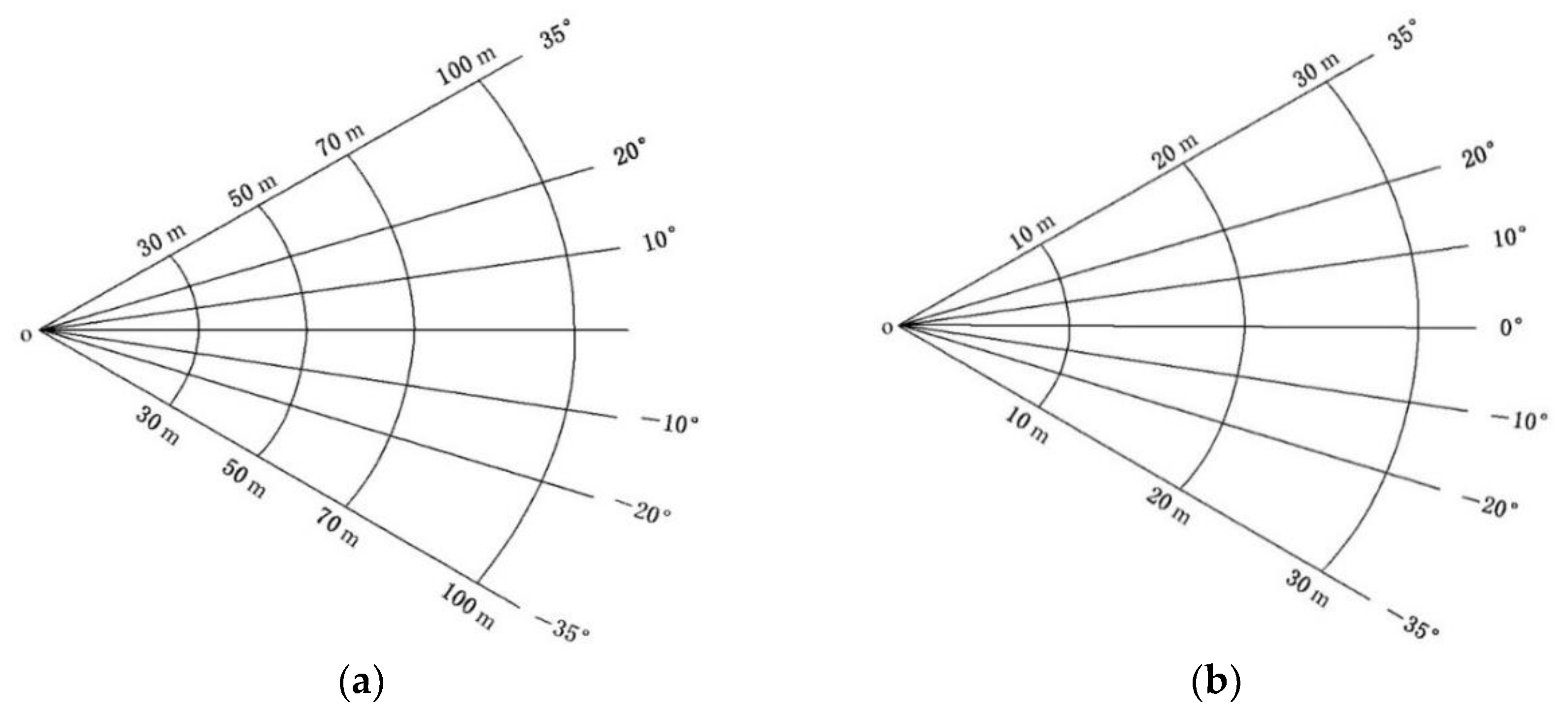
Figure 2.
Test diagram for illuminance of lighting system.
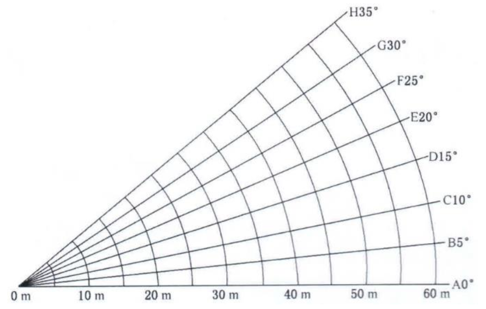
Figure 3.
Comparison chart of testing methods before and after optimization. (a) Current testing method. (b) Optimized testing method.
Figure 3.
Comparison chart of testing methods before and after optimization. (a) Current testing method. (b) Optimized testing method.
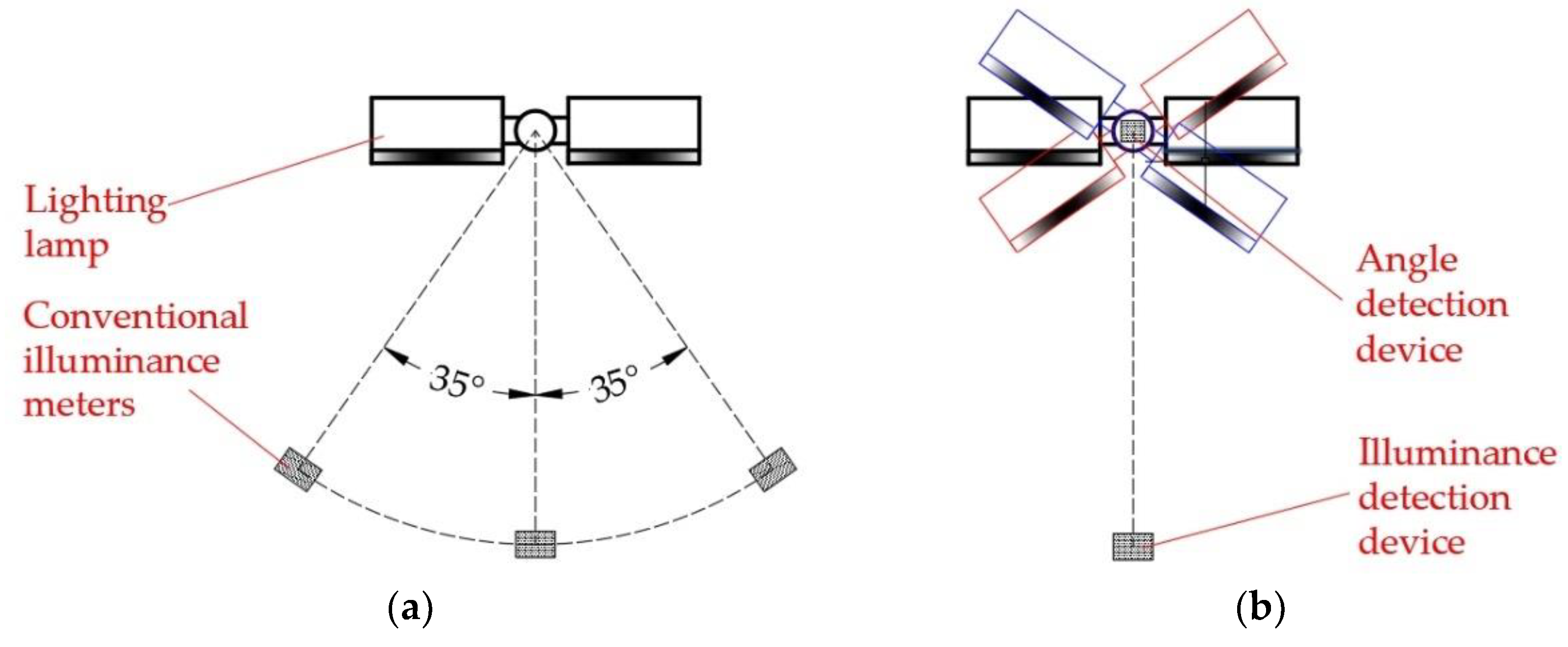
Figure 4.
Layout diagram of detection devices.
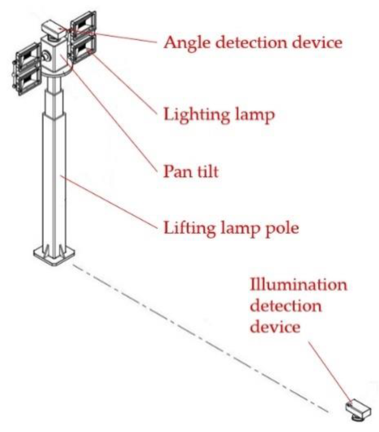
Figure 5.
Model diagram of the angle detection device.
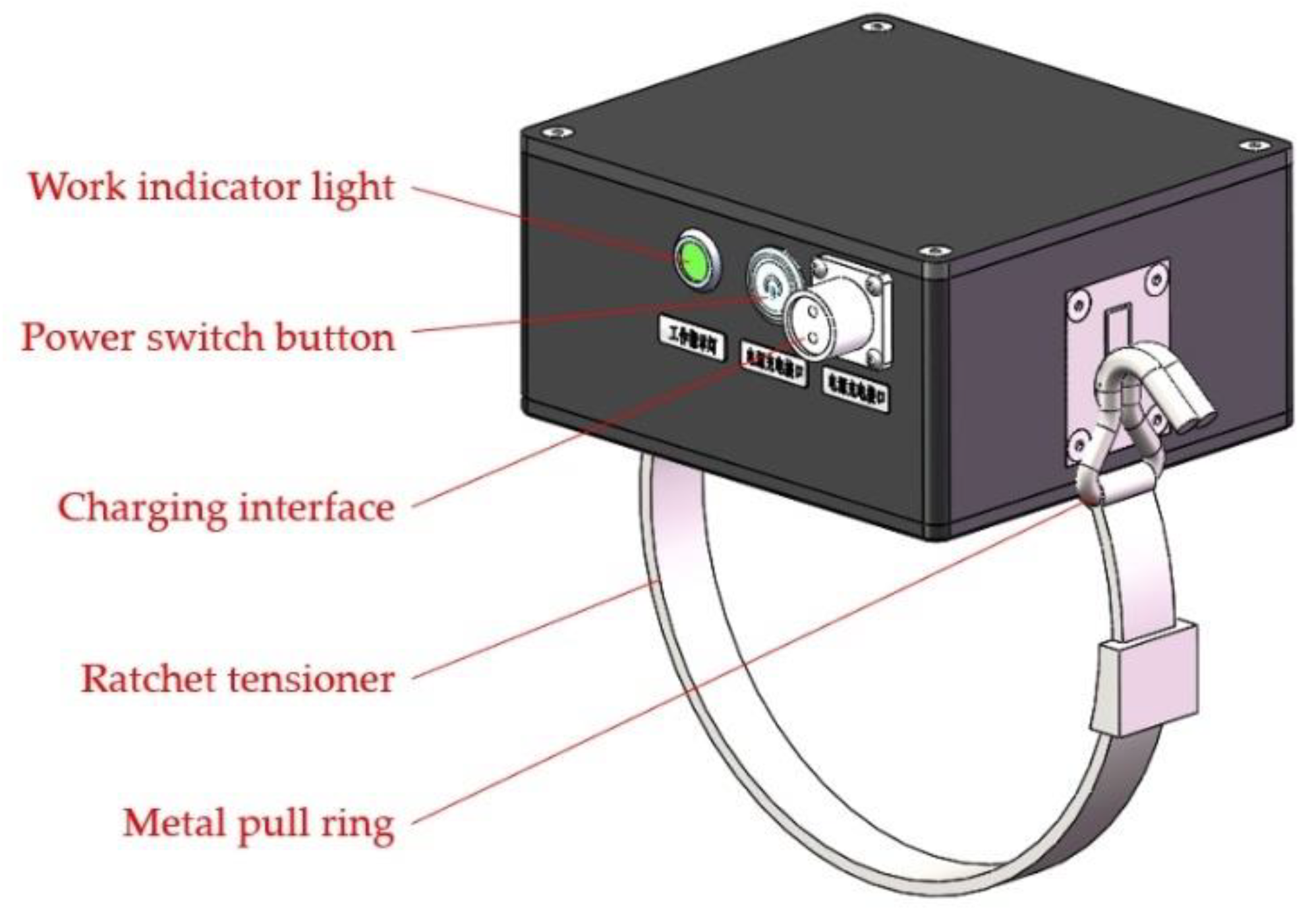
Figure 6.
Model diagram of the illuminance detection device.
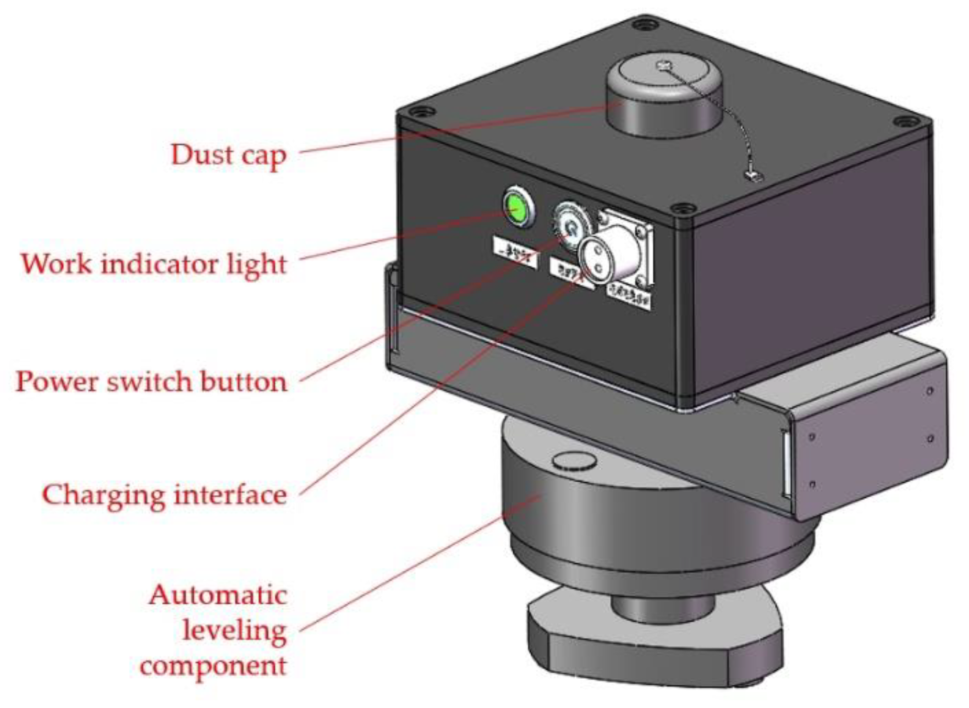
Figure 7.
Software diagram of data integration terminal.
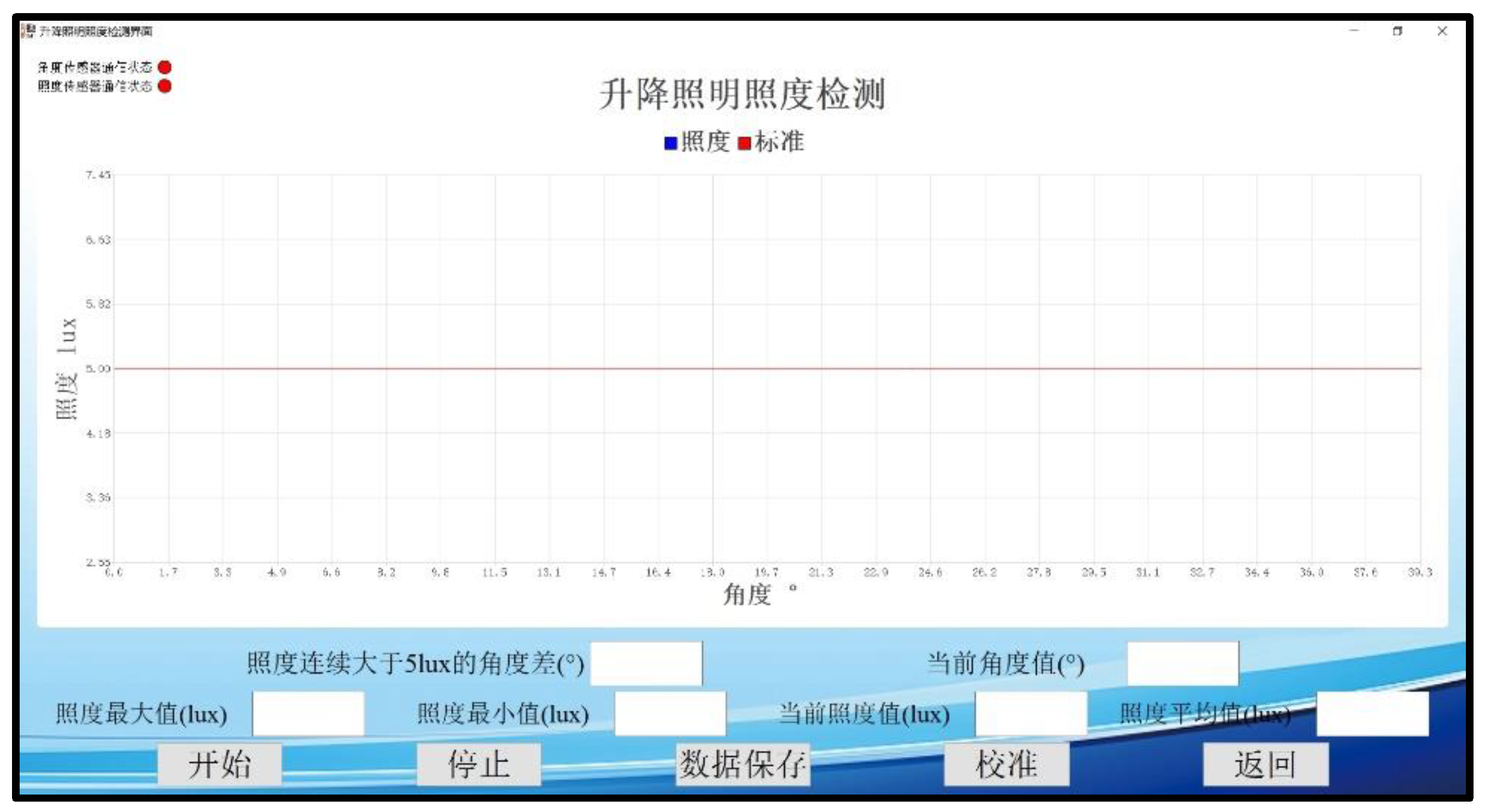
Figure 8.
Physical diagram of the entire testing device. (a) Angle detection device. (b) Ratchet tensioner. (c) Illuminance detection device. (d) Data integration terminal. (e) Toolbox for detection device.
Figure 8.
Physical diagram of the entire testing device. (a) Angle detection device. (b) Ratchet tensioner. (c) Illuminance detection device. (d) Data integration terminal. (e) Toolbox for detection device.
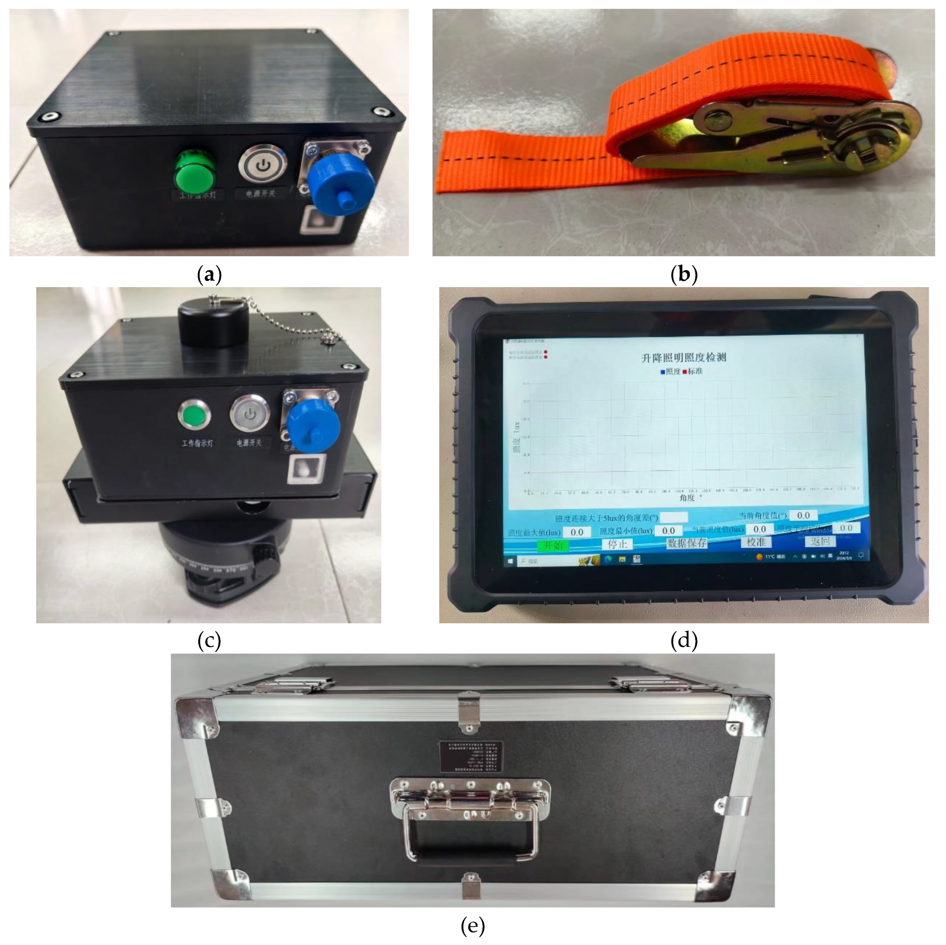
Figure 9.
Illumination meter A (a) and, B (b).
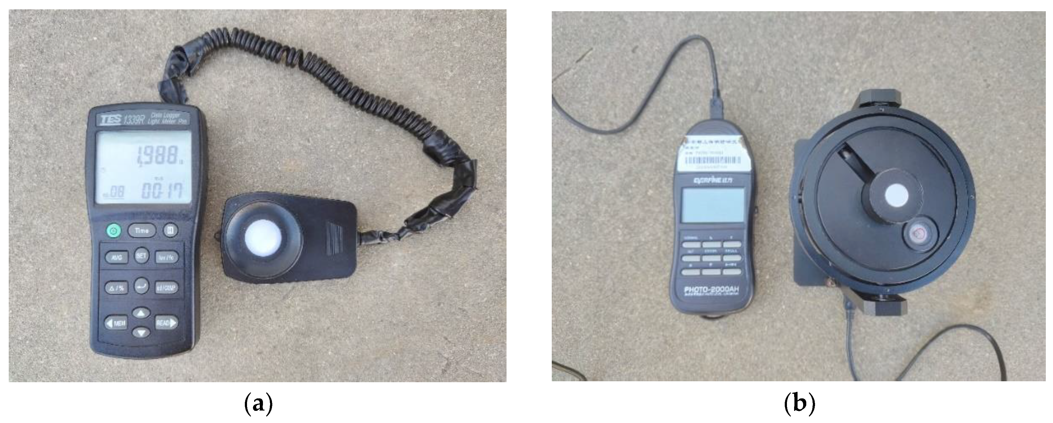

Table 1.
Comparison test of illuminance on a certain lighting fire fighting vehicle.
| Detection device | Angle (deg) | Illumination at 100 m of the main lighting lamp (lx) | Illumination at 30 m of the auxiliary lighting lamp (lx) |
|---|---|---|---|
| The integrated detection device for the “angle & illuminance” of the lifting lighting system on fire fighting vehicles | −35 | 6.3 | 5.4 |
| −20 | 6.7 | 5.6 | |
| -10 | 7.1 | 5.6 | |
| 0 | 7.2 | 5.8 | |
| +10 | 7.2 | 5.4 | |
| +20 | 7.0 | 5.5 | |
| +35 | 6.5 | 5.3 | |
| Illumination meter A | −35 | 6.4 | 5.4 |
| −20 | 6.7 | 5.4 | |
| -10 | 7.1 | 5.6 | |
| 0 | 7.2 | 5.8 | |
| +10 | 7.2 | 5.4 | |
| +20 | 7.0 | 5.4 | |
| +35 | 6.5 | 5.3 | |
| Illumination meter B | −35 | 6.4 | 5.4 |
| −20 | 6.7 | 5.6 | |
| -10 | 7.1 | 5.6 | |
| 0 | 7.2 | 5.9 | |
| +10 | 7.2 | 5.4 | |
| +20 | 7.0 | 5.4 | |
| +35 | 6.5 | 5.3 |
Table 2.
Comparison test of illuminance on a certain rescue fire fighting vehicle.
| Detection device | Angle (deg) | Illumination at 50 m (lx) |
|---|---|---|
| The integrated detection device for the “angle & illuminance” of the lifting lighting system on fire fighting vehicles | 0 | 9.8 |
| +5 | 9.8 | |
| +10 | 9.6 | |
| +15 | 9.2 | |
| +20 | 9.3 | |
| +25 | 9.3 | |
| +30 | 8.8 | |
| +35 | 8.8 | |
| Illumination meter A | 0 | 9.8 |
| +5 | 9.8 | |
| +10 | 9.6 | |
| +15 | 9.4 | |
| +20 | 9.3 | |
| +25 | 9.3 | |
| +30 | 8.8 | |
| +35 | 8.8 | |
| Illumination meter B | 0 | 9.8 |
| +5 | 9.8 | |
| +10 | 9.6 | |
| +15 | 9.2 | |
| +20 | 9.3 | |
| +25 | 9.3 | |
| +30 | 8.8 | |
| +35 | 8.8 |
Disclaimer/Publisher’s Note: The statements, opinions and data contained in all publications are solely those of the individual author(s) and contributor(s) and not of MDPI and/or the editor(s). MDPI and/or the editor(s) disclaim responsibility for any injury to people or property resulting from any ideas, methods, instructions or products referred to in the content. |
© 2024 by the authors. Licensee MDPI, Basel, Switzerland. This article is an open access article distributed under the terms and conditions of the Creative Commons Attribution (CC BY) license (http://creativecommons.org/licenses/by/4.0/).
Copyright: This open access article is published under a Creative Commons CC BY 4.0 license, which permit the free download, distribution, and reuse, provided that the author and preprint are cited in any reuse.


