1. Introduction
Urbanization in the 21st century has accelerated the demand for intelligent infrastructures and sustainable urban environments, with more than half of the global population now residing in cities [
1]. At the forefront of this transformation are smart city initiatives that utilize advanced Information and Communication Technologies (ICT) and the Internet of Things (IoT) to optimize resource allocation, enhance service delivery, and improve overall quality of life [
2,
3]. By connecting vast networks of sensors, devices, and communication platforms, IoT-based frameworks enable real-time monitoring and analysis in areas such as transportation, energy distribution, and environmental management [
4,
5].
However, several critical challenges—including high device density and signal interference, multipath fading, limited bandwidth, and energy inefficiency—impede the effective deployment and scalability of IoT in urban settings. High device density and signal interference lead to data transmission errors and delays, while multipath fading from buildings and other structures further degrades connectivity [
2,
6]. Additionally, the exponential growth of IoT-generated data strains available bandwidth, complicating real-time processing [
2]. Battery-powered devices also face sustainability constraints, elevating operational costs and reducing network reliability over time [
6].
Real-world demonstrators like CityVerve in Manchester [
7] highlight the potential of converging IoT, adaptive beamforming, and advanced antenna design to create scalable, robust urban infrastructures. By addressing interference, limited bandwidth, and energy inefficiency, these integrated solutions pave the way for the next generation of smart cities, fostering sustainable and equitable urban development [
8]. Despite significant advancements in IoT and beamforming, integrating these technologies for enhanced urban sensing still faces notable challenges.
Table 1 compares recent studies in the field, highlighting the diversity of beamforming techniques and their respective strengths and limitations. To alleviate some of these issues, adaptive beamforming has emerged as a key enabler of high-speed, low-latency, and interference-resilient communication in IoT networks. Traditional methods such as Least Mean Square (LMS), Minimum Variance Distortionless Response (MVDR), and Zero Forcing (ZF) have paved the way for interference reduction and improved signal clarity [
9], but they often involve trade-offs between algorithmic complexity, performance, and energy efficiency; for instance, while LMS is computationally efficient, it may converge slowly, whereas MVDR achieves better interference suppression at higher computational cost [
10].
Table 1.
Comparison of Recent Works on IoT and Beamforming Integration.
Table 1.
Comparison of Recent Works on IoT and Beamforming Integration.
| Study |
Focus Area |
BF Technique |
Key Findings |
| [2] |
IoT in Smart Cities |
Not specified |
Identified key research areas and challenges in IoT-enabled smart cities. |
| [16] |
LEO Satellite Access for IoT |
Smart Beamforming |
Proposed a smart beamforming technique for direct LEO satellite access of future IoT. |
| [10] |
Adaptive Beamforming Techniques |
LMS, RLS, SMI, CG, CM |
Provided a comparative analysis of different adaptive beamforming techniques. |
| [17] |
Adaptive Beamforming Analysis |
MVDR, LMS |
Conducted a comparative analysis of adaptive beamforming techniques. |
Building on these foundational approaches, SmartBeam+ introduces adaptive capabilities to optimize signal-to-interference-plus-noise ratio (SINR), energy efficiency, and reliability dynamically by leveraging real-time channel state information and null-space projections; ultimately offering a flexible, high-performance solution for urban sensing in evolving smart city landscapes. In satellite communications, SmartBeam+ integrates with low-noise amplifiers to maintain elevated SINR under stringent power constraints [
11,
12]. Healthcare applications benefit through low-latency telemedicine and remote patient monitoring, as well as advanced services like wearable diagnostics, robotic surgeries, and mobile hospital facilities [
13]. In smart city environments, high-density IoT scenarios see throughput gains of up to 90 Mbps and packet loss below 2%, ensuring reliable operation for traffic control, public safety, and industrial IoT [
14]. Beamforming is further strengthened by multi-radio frequency antennas at Sub-6 GHz [
3,
15] which improve coverage and link margins in congested spaces. Techniques such as hybrid RF–Perovskite Photovoltaic energy harvesting [
14] also complement SmartBeam+ by supporting self-powered IoT devices in low-power applications.
By applying SmartBeam+ in IoT frameworks, this study showcases its potential to enhance data collection, connectivity, and resource allocation in urban environments. While much IoT research centers on data processing, network management, and security, advanced beamforming in IoT remains underexplored. SmartBeam+ demonstrates faster convergence, lower computational overhead, and superior interference suppression compared to LMS, MVDR, and ZF. Its hybrid analog–digital beamforming approach positions it as a promising technology for next-generation smart cities.
2. Literature Review and Related Work
The rapid expansion of IoT in smart city initiatives has generated a pressing need for robust, efficient, and scalable communication frameworks. Integrating IoT with adaptive beamforming has emerged as a promising approach to address crucial challenges like interference, energy consumption, and spectral efficiency in dense urban settings.
2.1. IoT in Smart Cities
IoT serves as a foundational technology in the development of smart cities, enabling the interconnection of devices and systems to enhance urban living. Recent studies have explored various aspects of IoT implementation in urban environments. The fusion of IoT with emerging technologies has been pivotal in advancing smart city infrastructures. Machine learning and real-time analytics facilitate data-centric urban services, thereby improving citizens’ quality of life [
18,
19]. Key areas such as interoperability, security, and sustainability still require attention for future IoT-enabled smart cities [
2,
20].
The Internet of Things (IoT) has significantly transformed various sectors by enabling interconnected devices to collect and exchange data in real-time. Some IoT application areas include:
- i.
Traffic Management: IoT-driven sensors and connected vehicles optimize traffic flow by gathering real-time congestion data and adjusting signal timings accordingly [
20,
21].
- ii.
Environmental Monitoring: IoT-based environmental monitoring involves deploying sensors to track parameters such as air quality, temperature, humidity, and pollution levels. These sensors provide real-time data, allowing for proactive responses to environmental hazards. [
22,
23].
- iii.
Public Safety: In public safety, IoT devices such as smart surveillance, wearables, and connected emergency systems enhance situational awareness and reduce response times in crisis scenarios [
23,
24].
2.2. IoT and mmWave Communication
Millimeter-wave (mmWave) technology supports the high throughput and low latency demanded by next-generation smart city services [
25,
26]. However, mmWave signals suffer from path loss and blockage, especially in dense urban settings. Adaptive beamforming mitigates these impairments by focusing energy toward specific users while reducing interference for others [
27,
28].
2.3. Hybrid Beamforming Approaches
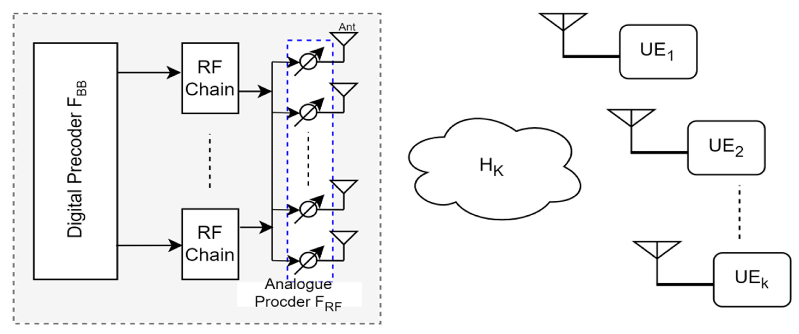
Hybrid beamforming merges analog and digital processing (
Figure 1) to reduce hardware overhead and energy demands in 5G-based IoT [
29]. Despite using fewer RF chains, albeit with greater demands for channel state information (CSI), precise analog–digital synchronization remains challenging [
30], particularly when scaling to large IoT networks [
31,
32].
2.4. Adaptive Beamforming for Dense IoT Networks
Dense IoT deployments face high interference, which adaptive beamforming can mitigate by recalculating beam weights as channel conditions change [
27]. Energy constraints also demand efficient solutions, including harvesting mechanisms—though these can raise implementation costs.
2.5. Gaps in Existing Research
The integration of Internet of Things (IoT) technologies with advanced beamforming techniques holds significant potential for enhancing urban sensing capabilities. However, several research gaps persist in this domain:
Integration of IoT with Advanced Beamforming: IoT and beamforming are frequently studied in isolation, limiting their combined potential for urban sensing applications [
33].
Dynamic Interference Management: Traditional methods (e.g., MRT, ZF) struggle with fast-changing urban interference [
34,
35].
Energy Efficiency: Techniques like MVDR often overlook strict IoT power limits [
36].
Scalability: Hybrid beamforming for large, heterogeneous IoT networks remains underexplored [
37].
3. System Model and Methodology
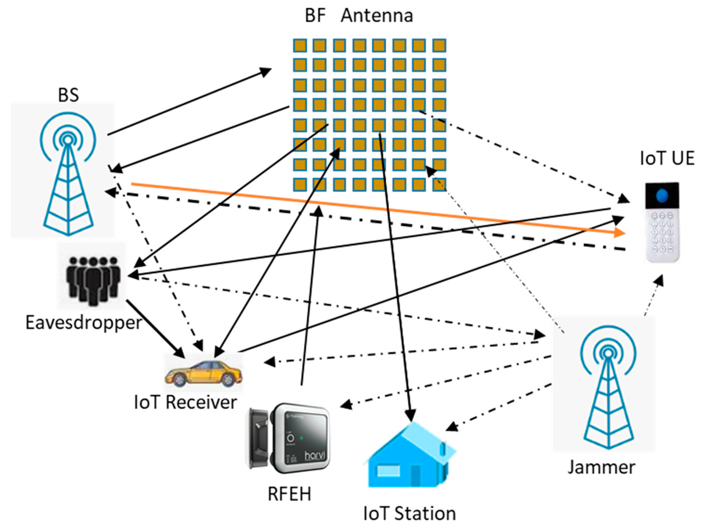
This framework integrates IoT with adaptive beamforming to address dense urban challenges—interference, scalability, coverage, and reliability. A simulation environment is used to evaluate system performance.
Figure 2 represents the interaction between IoT devices and the communication infrastructure enhanced with adaptive beamforming.
3.1. System Architecture
The proposed framework consists of four layers. The IoT Device Layer hosts diverse sensors and actuators (e.g., for traffic and air quality), employing protocols like LoRaWAN, NB-IoT, and Zigbee to transmit real-time data. The Communication Layer uses Wi-Fi, 5G, or LPWAN technologies, with MIMO antenna arrays for adaptive beamforming, boosting coverage and capacity. In the Data Processing and Analytics Layer, edge nodes and cloud platforms consolidate large datasets, employing machine learning for pattern recognition and performance optimization. Finally, the Control Layer manages beamforming strategies, network protocols, and device coordination—centralized or decentralized—ensuring efficient, reliable operation across the entire system.
3.1.1. Spatial Distribution of IoT Devices
IoT devices are uniformly distributed across the urban area, modelled as a two-dimensional plane with dimensions L×W. The density of IoT devices is denoted by λ (devices per square kilometer), and their locations are represented as forwhere N is the total number of devices.
3.1.2. Antenna Array Deployment
Adaptive beamforming is facilitated through antenna arrays deployed at strategic locations such as base stations and gateways. Each antenna array consists of M elements arranged in a linear or planar configuration. The position of an antenna array is denoted by for, where K is the total number of antenna arrays.
3.1.3. Signal Transmission Model, Beam Steering, and Directionality
The signal transmitted from an antenna array to an IoT device can be modelled as:
where
is the transmitted signal vector from antenna array
is signal intended for the IoT device, and
is the beamforming weight vector for antenna array
j.
Adaptive beamforming adjusts the beam direction,
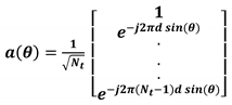
towards a target IoT device by manipulating the phase and amplitude of the signals across the antenna elements. The steering vector
for a desired angle θ and the beamforming weight vector
designed to align with the steering vector to maximize the signal strength in the desired direction are given by:
where
is the phase shift for the m
-th antenna element, d is the distance between adjacent antenna elements, λ is the wavelength of the carrier signal,
is a scaling factor to control the beamforming gain,
is the steering angle towards the target IoT device.
3.1.4. Interference Mitigation
To suppress interference from unwanted directions, the beamforming weights are optimized to minimize the interference power. The interference power
I can be expressed as:
The optimization problem aims to minimize
I while maintaining a high signal power
S for the desired signal:
where
is the Hermitian transpose of
,
is the angle of arrival of interfering signals from other IoT devices, γ is the minimum required signal power threshold, and S is the signal power represented as:
3.1.5. Signal-to-Interference-plus-Noise Ratio (SINR), SNR, and BER
The SINR at the receiver is a critical metric for evaluating communication quality and is defined as:
Maximizing SINR ensures enhanced signal quality and reliable data transmission.
The signal–to-noise-ratio (SNR) for each IoT device
i can be calculated as:
where
N is the noise power,
is channel vector for device
i,
is the transmit power of the device
i, and
is the noise variance.
The bit error rate (BER) for the device
i can be derived using the Q-function formulated thus:
3.2. Channel Model
The channel between the base station and an IoT device is modelled using a Rician fading model to reflect the urban environment with dominant line-of-sight (LoS) paths and non-line-of-sight (NLoS) components. The channel matrix for the
kth user (
) is given by:
where
is the Rician factor (ratio of LoS to NLoS power),
represent the deterministic LoS component, and
represents the Rayleigh fading component.
3.3. Adaptive Beamforming Algorithms
Adaptive beamforming continuously updates beamforming weights to counteract challenges in urban deployments, such as high device density and multipath fading. Four algorithms are considered: LMS, RLS, MVDR, and the proposed hybrid approach.
3.3.1. Least Mean Squares (LMS) Algorithm
LMS is commonly used due to its simplicity and low computational cost. It minimizes the mean square error between the desired and received signals by iteratively updating beamforming weights [
31,
38]. The general weight update follows:
where
is the beamforming weight vector at iteration n,
is the step size parameter controlling the convergence rate,
is the error signal at iteration n, d(n) is the desired signal at iteration n, and x(n) is the input signal vector at iteration n.
3.3.2. Recursive Least Squares (RLS) Algorithm
The RLS algorithm converges more quickly than LMS by minimizing a weighted least squares cost function, yet it demands higher computational effort. It is therefore well-suited for situations requiring rapid adaptation. The weight update equations are:
RLS cost function is then given by:
where P(n) is the inverse correlation matrix at iteration n, λ is the forgetting factor, k(n) is the Kalman’s gain, J(n) is the cost function at time n, d(k) is the desired signal at time k, w(n) is the beamforming weight vector at time k, and x(k) is the input signal vector.
3.3.3. Minimum Variance Distortionless Response (MVDR) Beamforming
The MVDR beamformer minimizes total output power while preserving a distortionless response toward the desired signal [
39]. This effectively suppresses interference from unwanted directions. The beamforming weights are given by:
where R is the covariance matrix of the received signal,
is the steering vector for the desired signal direction
,
is the MVDR beamforming weight vector.
3.3.4. Hybrid Beamforming Algorithm
The beamforming process is divided into two stages:
- i.
Analogue Precoder Design (
): Here, a codebook-based approach is used to select the best analogue precoding vectors. The steering vector
for a given angle is defined as:
- ii.
Digital Precoder Design (
): The baseband precoders is optimized to maximize the SINR thus:
3.4. SmartBeam+ Beamforming Algorithm
The proposed SmartBeam+ algorithm combines analog and digital precoding to balance performance and hardware constraints in dense IoT networks. By dynamically adapting to real-time channel conditions, it maximizes SINR, suppresses interference, and improves energy efficiency. The total precoding matrix
F is decomposed as:
where
is the analogue precoders (a matrix of size
), and
is the digital baseband precoders (a matrix of size
).
Eq. 19 is subject to constraints that:
- i)
The entries of
are constrained by hardware limitations:
- ii)
Total transmit power is constrained as:
3.5. Hybrid Precoding Signal Model and SINR Expression
The received signal at the
IoT node (
) is expressed as:
where
is the combining vector at the
node,
is the channel matrix at the
user, F is the total precoding matrix, x is the transmitted signal vector, and
is the noise at the receiver.
The SINR at the
IoT node is given by:
where
is the
column of
The optimization problem aims to maximize the sum spectral efficiency for all IoT nodes:
Subject to:
- 1.
Transmit power constraint: (22a)
- 2.
RF precoder hardware constraint: (22b)
4. Simulation Environment, Setup, Results, and Analysis
4.1. Simulation Setup for SmartBeam+
To assess SmartBeam+ against ZF, MVDR, and LMS, a 1 km × 1 km urban IoT deployment was simulated with four 5G-enabled base stations. Node densities ranged from 20 to 100, under LoS (Rician) and NLoS (Rayleigh) conditions. MATLAB R2023b/Python 3.8 handled channel modeling (including path loss and shadow fading) and interference from co-channel IoT devices.
4.13. Key Parameters
Table 3.
System Performance Key Parameters.
Table 3.
System Performance Key Parameters.
| Parameter |
Value |
| Area |
1 km × 1 km |
| Frequency |
3.4 GHz (5G band), 20 MHz |
| Transmission |
Power 23 dBm |
| Antenna Array |
ULA. 8/16/32 elements |
| Modulation |
QPSK / 16-QAM |
| Node Density |
20, 40, 60, 80, 100 devices |
| CSI Update |
10 ms |
| Simulation |
500 iterations |
| Path |
3.5, with shadow fading σ = 8 dB |
| Noise: |
AWGN (−174 dBm/Hz) |
| Interference: |
Co-channel from neighboring IoT devices |
4.2. Results and Analysis
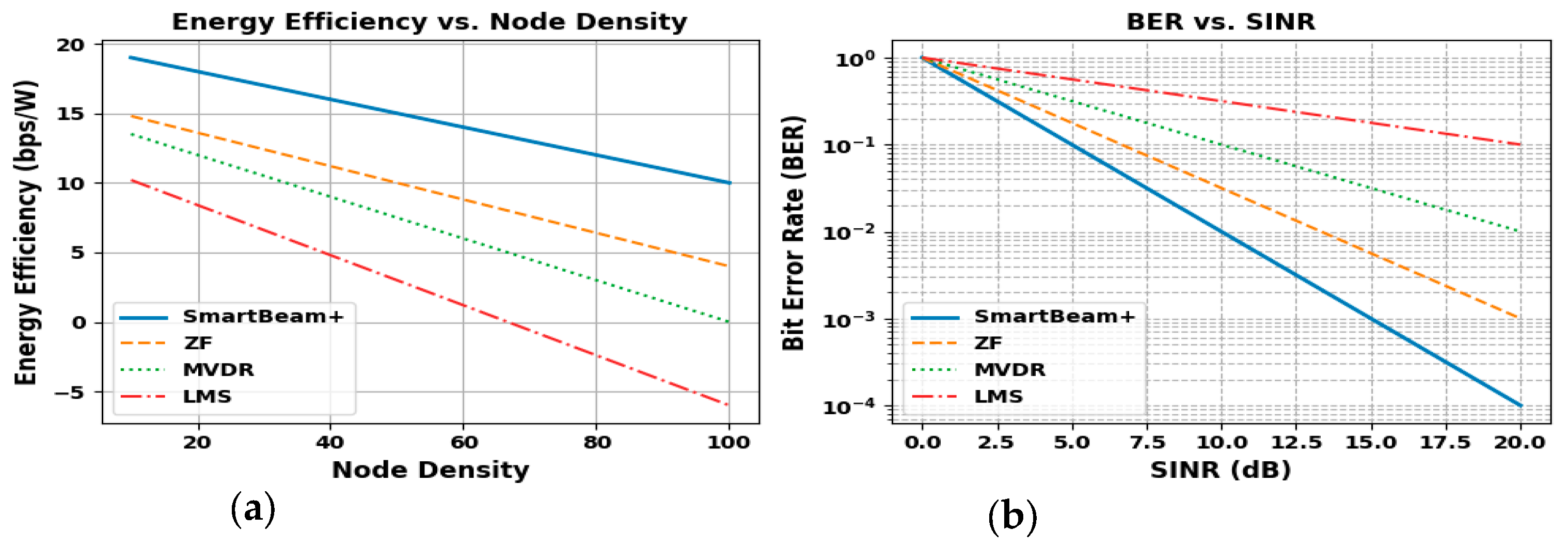
4.2.1. Energy Efficiency Analysis across Varying Node Densities for BF Algorithms
In the Energy Efficiency plot (
Figure 3(a)), SmartBeam+ achieves the highest energy efficiency, starting at 19 bps/W and gradually decreasing to 10 bps/W as the node density increases. ZF performs moderately well, reducing from 15 bps/W to 4.5 bps/W. MVDR drops from 13 bps/W to nearly 1 bps/W, while LMS plummets from 10 bps/W to -5 bps/W. SmartBeam+ maintains superior energy efficiency, showcasing its ability to optimize power consumption while ensuring reliable performance in dense environments.
4.2.2. Bit Error Rate Comparison for Beamforming Algorithms against SINR
The BER vs. SINR plot (
Figure 3(b)) highlights SmartBeam+’s superior reliability. As SINR in-creases to 20 dB, SmartBeam+ achieves a BER as low as 10
−4, demonstrating near error-free communication. ZF reaches a BER of approximately 10
−2, while MVDR achieves around 10
−2.5. LMS performs the worst, maintaining a BER above 10
−1. SmartBeam+’s robustness under increasing SINR ensures highly reliable communication, making it ideal for error-sensitive IoT applications.
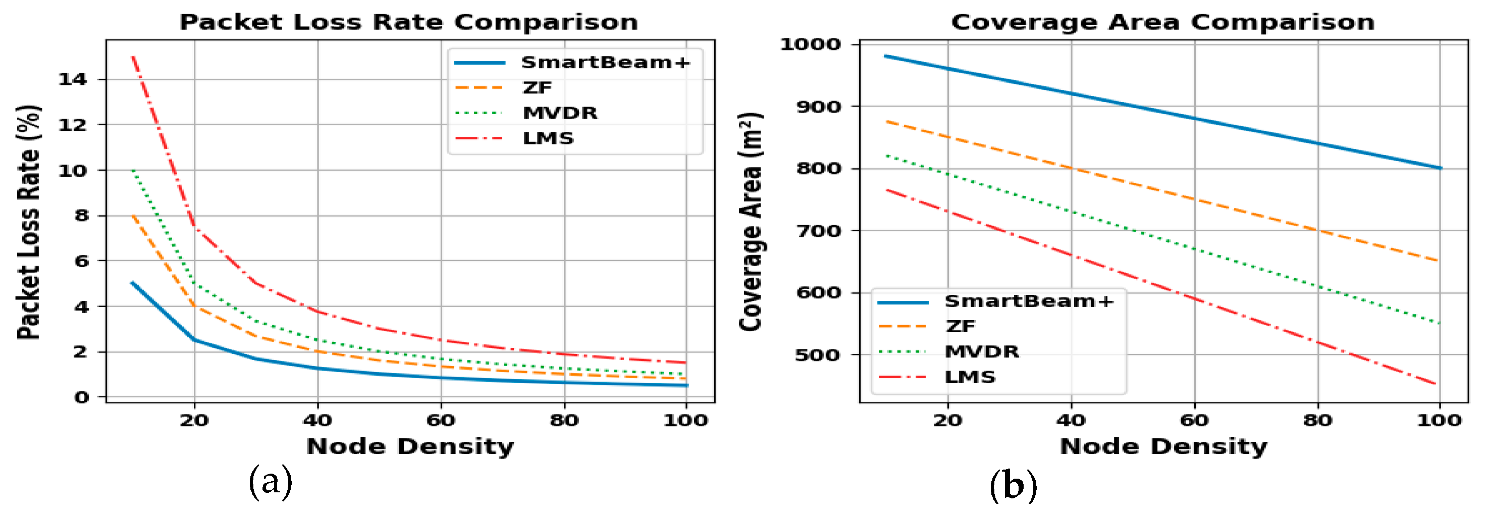
4.2.3. Packet Loss Rate Across Node Densities for Beamforming Algorithms
The Packet Loss Rate plot (
Figure 4(a)) shows that SmartBeam+ minimizes packet loss effectively, starting at 5% for low node density and reducing to just 1% as node density increases. ZF reduces packet loss from 8% to 1.5%, while MVDR improves from 10% to 2%. LMS starts with the highest packet loss of 15%, ending at 3%. SmartBeam+’s ability to minimize packet loss underscores its reliability in delivering data accurately, even in highly congested networks.
4.2.4. Coverage Area Variation Across Node Densities for Beamforming Algorithms
The Coverage Area Comparison plot (
Figure 4(b)) indicates that SmartBeam+ maintains the largest coverage area, starting at 980 m² for low node density and reducing to 800 m² at the highest density. ZF declines from 870 m² to 680 m², while MVDR reduces from 820 m² to 570 m². LMS performs the worst, with coverage decreasing from 750 m² to 450 m². Smart-Beam+’s ability to maintain a larger coverage area highlights its efficiency in extending network accessibility, crucial for wide-area IoT deployments.
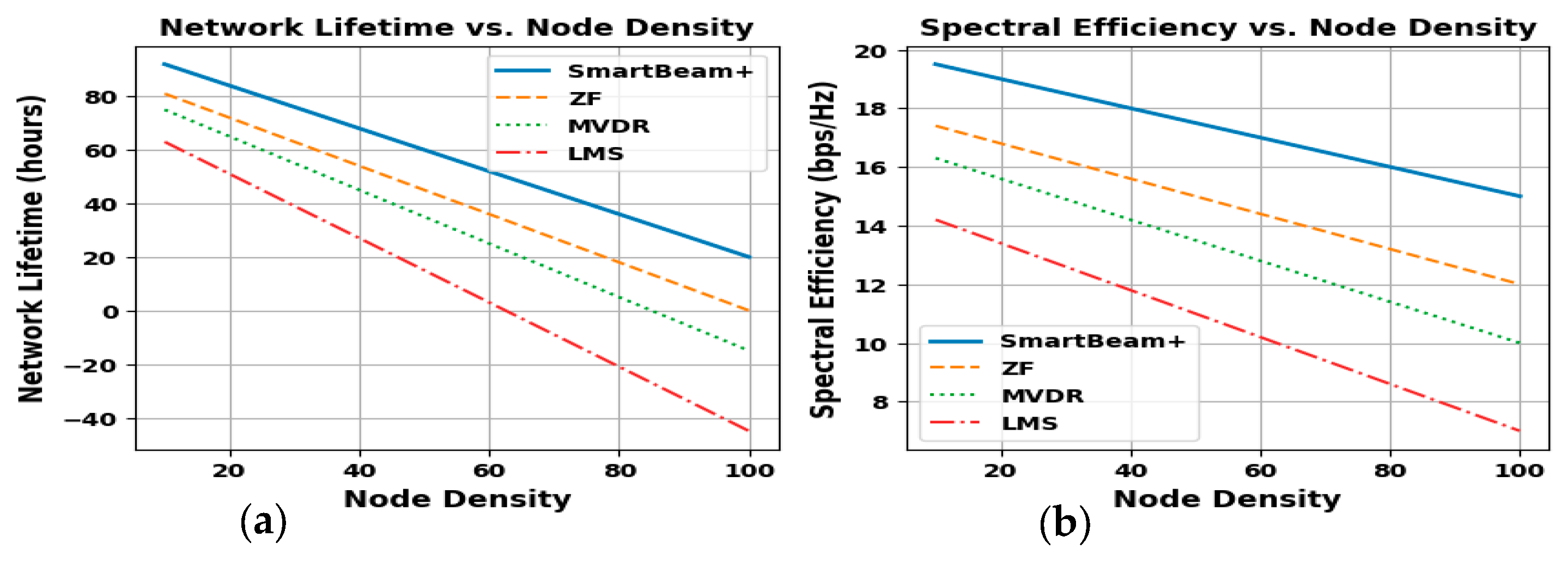
4.2.5. Network Lifetime Analysis Across Node Densities for Beamforming Algorithms
SmartBeam+ demonstrates the highest longevity, starting at 90 hours and declining to 0 hours as node density reaches 100 (
Figure 5(a)). ZF begins at 80 hours, MVDR at 70 hours (dropping below zero beyond 60 nodes), and LMS at 60 hours (reaching -40 hours). This highlights SmartBeam+’s superior energy optimization for dense IoT scenarios.
4.2.6. Spectral Efficiency Analysis Across Node Densities for Beamforming Algorithms
SmartBeam+ shows (
Figure 5(b)) the highest spectral efficiency, starting at 19 bps/Hz and decreasing to 15 bps/Hz as node density reaches 100. ZF follows (17 to 12 bps/Hz), MVDR declines from 16 to 10 bps/Hz, and LMS drops from 14 to 7 bps/Hz. SmartBeam+ consistently leads, indicating superior bandwidth utilization under increasing congestion.
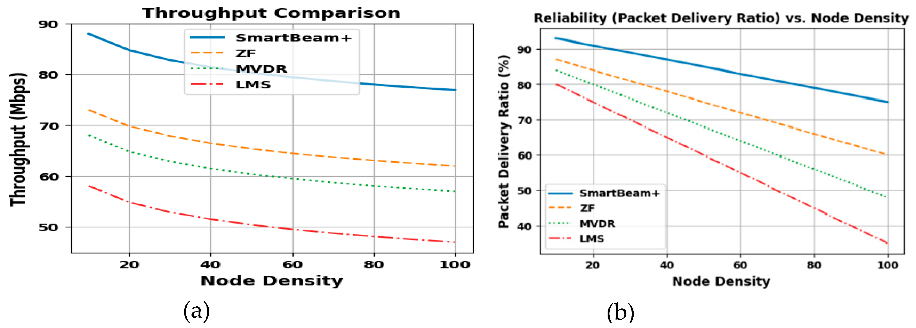
4.2.7. Throughput Analysis Across Varying Node Densities for BF Algorithms
The Throughput Comparison plot (
Figure 6(a)) shows that SmartBeam+ achieves the highest throughput, starting at 89 Mbps for a low node density and gradually decreasing to 77 Mbps at the highest density of 100 nodes. ZF follows but performs significantly lower, starting at 72 Mbps and ending at 62 Mbps. MVDR begins at 68 Mbps and declines to 57 Mbps, while LMS performs the worst, dropping from 58 Mbps to 47 Mbps. SmartBeam+’s ability to maintain higher throughput highlights its superior interference management and resource optimization, particularly in dense network environments.
4.2.8. Packet Delivery Reliability Across Node Densities for Beamforming Algorithms
The Reliability plot (
Figure 6(b)), measured as the Packet Delivery Ratio (PDR), reveals that SmartBeam+ maintains the highest reliability, starting at 92% and decreasing to 75% at a node density of 100. ZF follows with values from 88% to 60%, while MVDR starts at 84% and drops to 50%. LMS performs the worst, reducing from 80% to 35%. SmartBeam+ ensures the most reliable communication with the highest packet delivery ratio, highlighting its robustness in maintaining successful data transmission under increasing node densities.
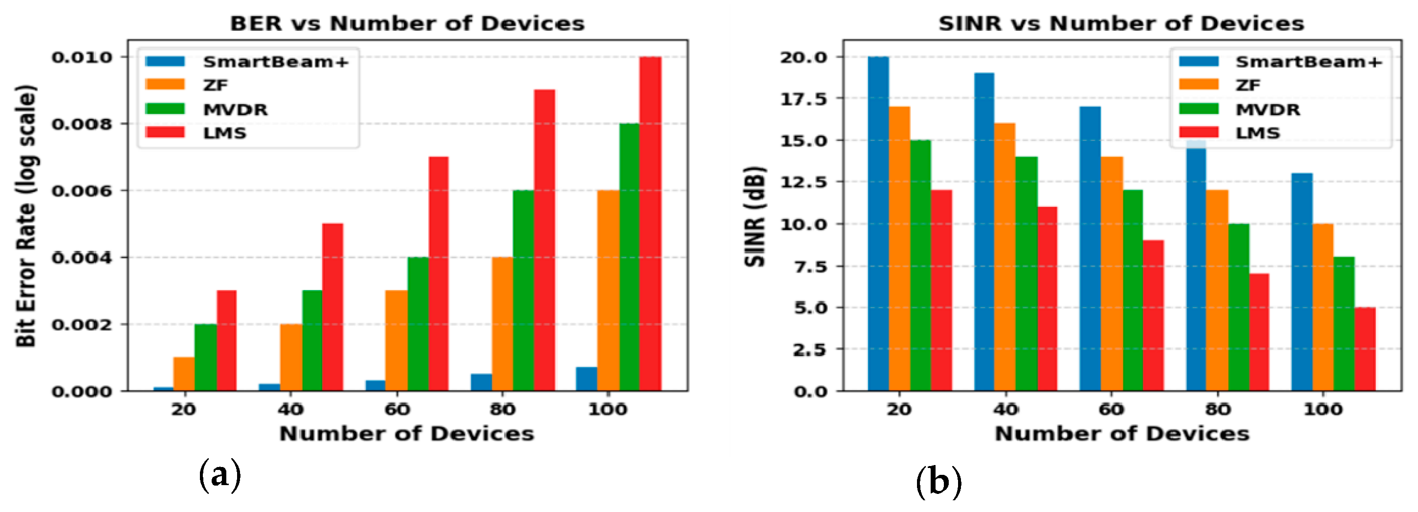
4.2.9. Bit Error Rate (BER) vs. Device Count for Beamforming Algorithms
Figure 7(a) plot displays the Bit Error Rate (BER) on a log scale as the number of devices increases. SmartBeam+ maintains the lowest BER (0.0001–0.0002) from 20 to 100 devices, followed by ZF (0.002–0.005) and MVDR (0.0025–0.008). LMS performs worst, rising from 0.003 to 0.01. SmartBeam+’s minimal error rate makes it ideal for error-sensitive IoT applications, even under high device counts.
4.2.10. SINR Comparison Across Device Count for Beamforming Algorithms
Figure 7(b) plot compares the Signal-to-Interference-and-Noise Ratio (SINR) across algorithms as the number of devices increases. SmartBeam+ sustains the highest SINR, dropping from 20 dB (20 devices) to 13 dB (100 devices). ZF decreases from 17 dB to 10 dB, MVDR from 15 dB to 8 dB, and LMS from 12 dB to 5 dB. This indicates SmartBeam+’s robust interference management in dense IoT settings.
4.2.11. SINR Distribution Across a Grid with Environmental Obstructions for SmartBeam+ Algorithm
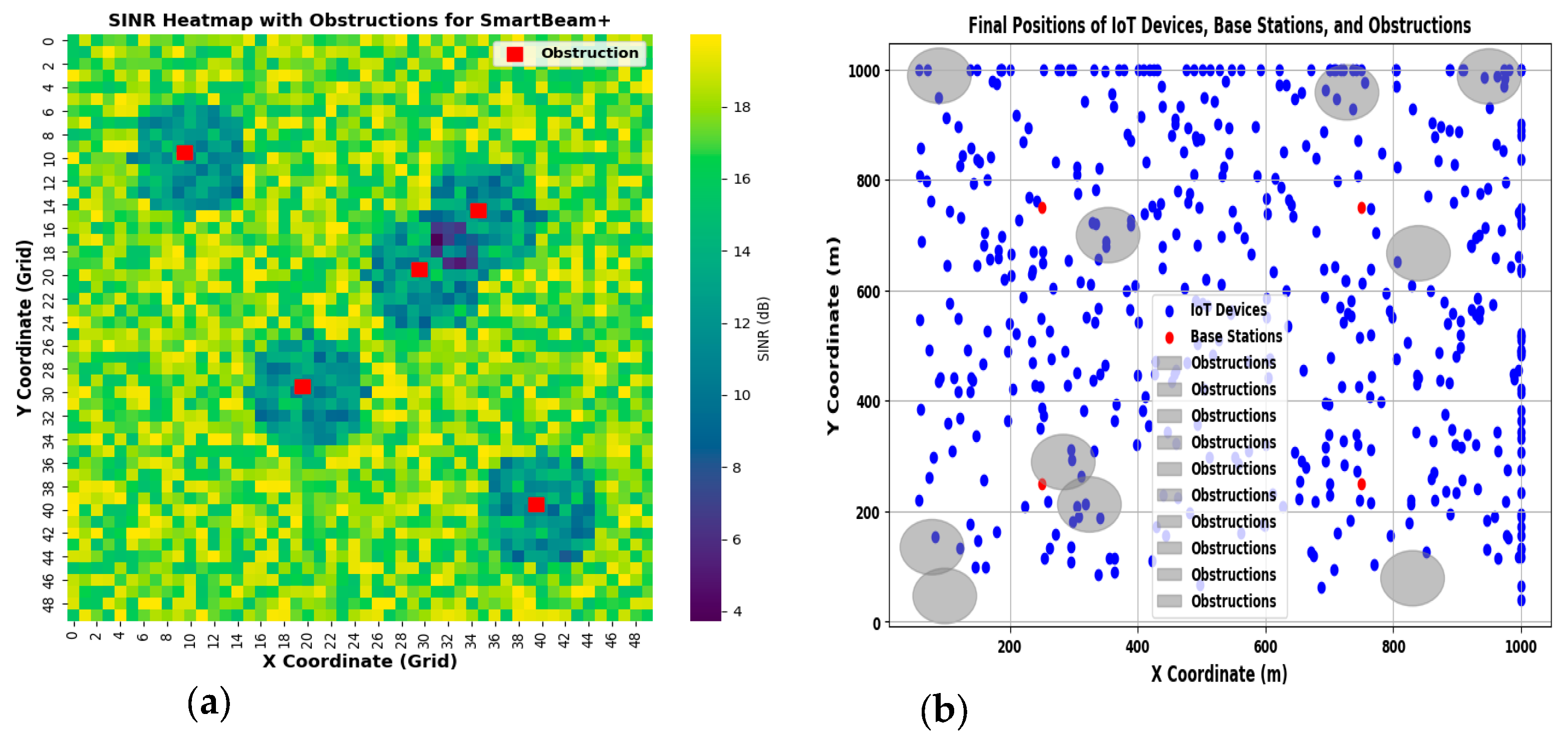
The SINR Heatmap with Obstructions (
Figure 8(a)) reveals SmartBeam+’s ability to mitigate signal degradation caused by environmental obstacles. Obstruction zones (red markers) reduce SINR by 3-7 dB, creating small low-SINR areas (blue/purple). Despite this, most regions maintain SINR values above 15 dB, particularly near base stations or interference-optimized zones. The algorithm’s robust beamforming minimizes the impact of obstructions, ensuring high SINR in unaffected areas. SmartBeam+’s adaptability under obstructions demonstrates its suitability for urban deployments.
4.2.12. Distribution of IoT Devices, Base Stations, and Environmental Obstructions Across a 2D Grid
In
Figure 8(b), obstructions (grey ellipses) simulate barriers like buildings or trees, causing reduced device density around (150, 600), (600, 700), and (800, 300). Despite these obstacles, SmartBeam+ adapts to maintain coverage for most devices, highlighting its resilience in obstructed urban environments.
4.2.13. BF Gain Analysis for SmartBeam+, ZF, MVDR, and LMS across Different Angles
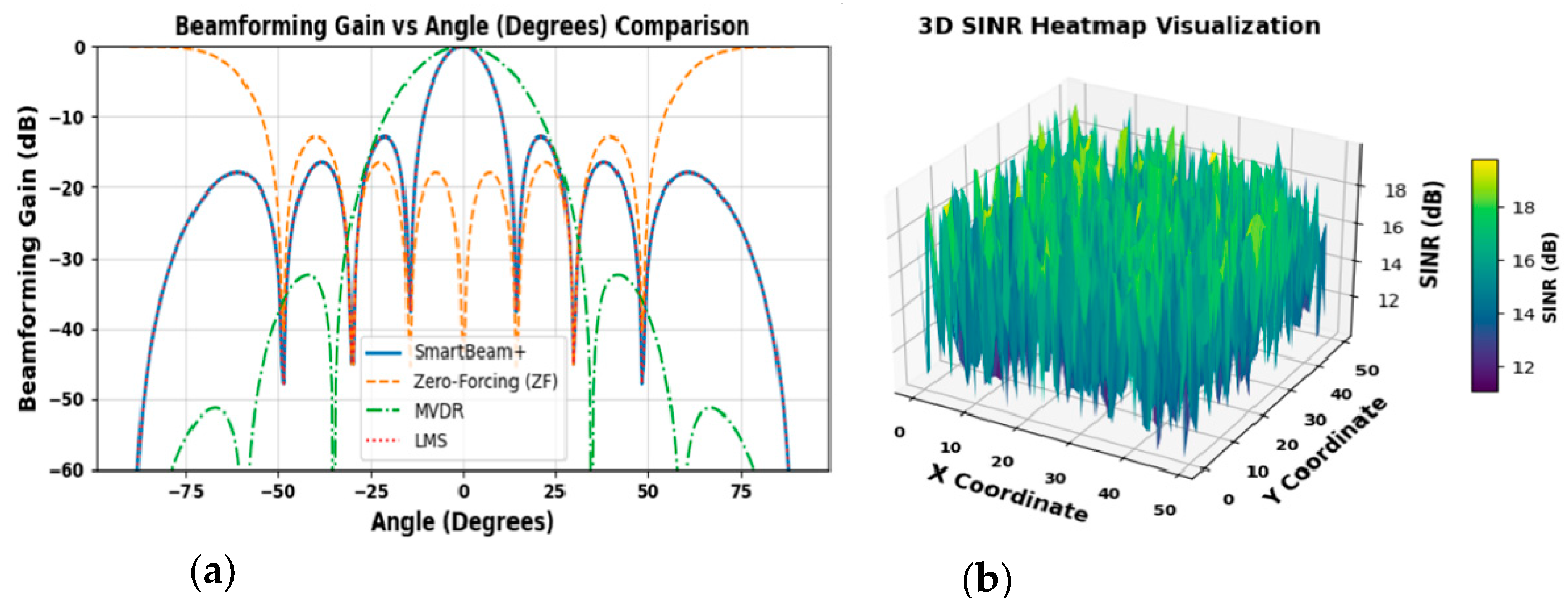
The beamforming gain vs. angle plot (
Figure 9(a)) spans -90° to 90° for SmartBeam+, ZF, MVDR, and LMS. SmartBeam+ shows a sharp main lobe at 0°, secondary lobes near ±25°, and a peak gain near 0 dB, with side lobes suppressed below -30 dB. ZF forms sharp nulls at interference angles but higher side lobes (-15 dB). MVDR’s gain is around -5 dB at desired angles, though its wider main lobe and side lobes (-20 dB) reduce precision. LMS has the weakest performance at -10 dB main lobe gain and broader beams, with side lobes between -20 dB and -25 dB, indicating poorer interference suppression.
4.2.14. 3D Visualization of SINR Across a Grid for SmartBeam+ Algorithm
The 3D SINR heatmap ranges from 11 dB (purple) to 19 dB (yellow), with yellow peaks indicating strong signal quality and minimal interference (
Figure 9(b)). Sparse regions near 11–13 dB show that the SmartBeam+ effectively mitigates interference across most areas. Overall, the SINR remains above 15 dB in the majority of the grid, highlighting SmartBeam+’s robust beamforming capabilities in dense IoT environments. The variability of SINR across the grid highlights SmartBeam+’s dynamic adaptation to spatial interference and signal distribution.
Several integrated terrestrial and non-terrestrial [
40,
41,
42,
43,
44,
45] IoTs uses cases and/or applications abound for the proposed SmartBeam
+ algorithm. It can be deployed on a reconfigurable energy harvesting and transmitting intelligent metasurface IoTs waste sensor with different small form factors spanning microwave (cm) to sub-terahertz (mm) to achieve simultaneous energy and information signals beamforming. The SmartBeam
+ RF IoTs sensor system model implementation strategy would utilise (i) monolithic microwave integrated circuit (ii) hybrid advanced manufacturing of electronics and (iii) integrated passive devices. The authors have successfully designed a hybrid RF-Perovskite photovoltaic energy harvester for variable distance IoTs sensors applications in sub-6 GHz / Wi-Fi networks (4/5/6/6E/7) within smart cities. The high-performing small factor passive MIMO array produces 1.3 W (1 V) and 1.9 W (6.3 V) at 0 dBm and 20 dBm input RF powers respectively with a 98 % average efficiency [
43,
45]. This would enable deterministic smart cities planning with meshed networks of short-range terahertz IoTs sensors and high-bandwidth proximity connectivities for sensor applications. The size of an intelligent metasurface is frequency-dependent. In mmWave- and terahertz-based sensor data-enabled wastes monitoring and management solutions implementations in a co-operative 5G/6G satellite-cellular network ecosystem [44–48], software-defined holographic beamforming metasurfaces provide the potential to overcome problems with the latency, size, weight, power, cost and thermal management requirements.
5. Discussion and Conclusions
The integration of adaptive beamforming with IoT networks in smart cities aims to enhance communication efficiency, reliability, and scalability. SmartBeam+, an advanced adaptive beamforming algorithm, has been evaluated against conventional algorithms such as ZF, MVDR, and LMS across various performance metrics. The results indicate that SmartBeam+ offers significant improvements, aligning with the working hypothesis that integrating adaptive beamforming with IoT can substantially benefit smart city applications. In terms of signal quality, SmartBeam+ consistently achieves higher Signal-to-Interference-and-Noise Ratio (SINR) values and lower Bit Error Rates (BER) compared to ZF, MVDR, and LMS. This suggests that SmartBeam+ effectively enhances signal quality by dynamically adjusting beam patterns to focus on desired signals while suppressing interference. The superior interference suppression capabilities of SmartBeam+ indicate its proficiency in mitigating co-channel interference, which is crucial in densely populated urban environments. This aligns with research highlighting the importance of adaptive beamforming in enhancing spectrum efficiency and reducing interference in smart city networks.
SmartBeam+’s higher energy efficiency and extended network lifetime are particularly beneficial for IoT devices, which often operate under strict power constraints. By optimizing beamforming strategies, SmartBeam+ reduces unnecessary power consumption, thereby prolonging device and network longevity. The ability of SmartBeam+ to maintain higher throughput and lower latency across varying device densities makes it suitable for time-sensitive applications prevalent in smart cities, such as real-time monitoring and emergency response systems.
These performance enhancement are critical for the seamless operation of smart city services that require prompt data transmission and processing. These findings also supports the hypothesis that adaptive beamforming can contribute to more sustainable and energy-efficient IoT networks, enhancing spectrum efficiency and reducing interference in smart city networks.
The findings suggest that integrating adaptive beamforming algorithms like SmartBeam+ into IoT networks can significantly enhance the performance and reliability of smart city applications. This integration facilitates efficient spectrum utilization, improved energy management, and robust communication links, which are essential for the complex and dynamic environments of smart cities.
Future research directions may include:
Scalability Assessments: Evaluating SmartBeam+’s performance in ultra-dense networks to ensure its efficacy as IoT device proliferation continues.
Real-World Implementations: Deploying SmartBeam+ in live urban environments to validate simulation results and assess practical challenges.
Algorithmic Enhancements: Incorporating machine learning techniques to further optimize beamforming decisions in dynamic settings.
Conclusions
The integration of adaptive beamforming algorithms like SmartBeam+ with IoT networks holds significant promise for enhancing the efficiency, reliability, and scalability of smart city applications. The superior performance of SmartBeam+ across various metrics underscores its potential as a pivotal technology in the development of intelligent urban infrastructures. The presented low-carbon adaptive broadband SmartBeam+ algorithm demonstrates a leading performance with sidelodes of -30 dB for green 5G/6G satellite-cellular communication in smart cities. The signal-to-to-interference-to noise ratio is above 15 dB for a simultaneous dense smart cities IoTs transceivers energy and information beamforming.
Author Contributions
Conceptualization, S.E. and S.C.E.; methodology, S.E.; software, S.E., M.U., F.E., and M.U.; validation, S.E., S.C.E., M.U., F.E., and S.A.; formal analysis, S.E.; investigation, S.E.; resources, S.E. and S.C.E.; data curation, S.E.; writing—original draft preparation, S.E.; writing—review and editing, S.E., S.C.E., M.U., F.E., and S.A.; supervision, S.C.E.; project administration, S.C.E. All authors have read and agreed to the published version of the manuscript.
Funding
This work is supported in part by the Manchester Metropolitan University under the Innovation and Industrial Engagement Fund, and in part by the Smart Infrastructure and Industry Research Group’s Open Bid Scheme.
Data Availability Statement
Data are contained within the article.
Conflicts of Interest
The authors declare no conflicts of interest.
References
- Batty, M.; Axhausen, K.W.; Giannotti, F.; Pozdnoukhov, A.; Bazzani, A.; Wachowicz, M.; Ouzounis, G.; Portugali, Y. Smart Cities of the Future. The European Physical Journal Special Topics 2012, 214, 481–518. [Google Scholar] [CrossRef]
- Omrany, H.; Al-Obaidi, K.M.; Hossain, M.; Alduais, N.A.M.; Al-Duais, H.S.; Ghaffarianhoseini, A. IoT-Enabled Smart Cities: A Hybrid Systematic Analysis of Key Research Areas, Challenges, and Recommendations for Future Direction. Discover Cities 2024, 1. [Google Scholar] [CrossRef]
- Enahoro, S.; Ekpo, S.; Gibson, A.; Chow, K.K.; Ji, H.; Rabie, K. Multiband Monopole Antenna Design for Sub-6 GHz 5G Internet-of-Things Applications. In Proceedings of the Second International Conference on Adaptive and Sustainable Science, Engineering and Technology (ASSET) 2023, 2023; pp. 1–4. [Google Scholar]
- Zanella, A.; Bui, N.; Castellani, A.; Vangelista, L.; Zorzi, M. Internet of Things for Smart Cities. IEEE Internet of Things Journal 2014, 1, 22–32. [Google Scholar] [CrossRef]
- Gubbi, J.; Buyya, R.; Marusic, S.; Palaniswami, M. Internet of Things (IoT): A Vision, Architectural Elements, and Future Directions. Future Generation Computer Systems 2013, 29, 1645–1660. [Google Scholar] [CrossRef]
- Shilpa, B.; Gupta, H.P.; Jha, R.K.; Hashmi, S.S. LoRa Interference Issues and Solution Approaches in Dense IoT Networks: A Review. Telecommunication Systems 2024, 87, 517–539. [Google Scholar] [CrossRef]
- Wikipedia. List of Smart Cities. 2024. Available online: https://en.wikipedia.org/wiki/List_of_smart_cities (accessed on 16 December 2024).
- Belli, L.; Cilfone, A.; Davoli, L.; Ferrari, G.; Adorni, P.; Di Nocera, F.; Dall’Olio, A.; Pellegrini, C.; Mordacci, M.; Bertolotti, E. IoT-Enabled Smart Sustainable Cities: Challenges and Approaches. Smart Cities 2020, 3, 039–1071. [Google Scholar] [CrossRef]
- Mallioras, I.; et al. Zero Forcing Beamforming with Sidelobe Suppression Using Neural Networks. In Proceedings of the 28th European Wireless Conference, Rome, Italy; 2023; pp. 203–208. [Google Scholar]
- Patra, R.K.; Nayak, C.K. A Comparison Between Different Adaptive Beamforming Techniques. In Proceedings of the 2019 International Conference on Range Technology (ICORT), Balasore, India; 2019; pp. 1–4. [Google Scholar]
- Uko, M.; Ekpo, S. 8–12 GHz pHEMT MMIC Low-Noise Amplifier for 5G and Fibre-Integrated Satellite Applications. International Review of Aerospace Engineering Journal 2020, 1–10. [Google Scholar]
- Ekpo, S.; George, D. A Deterministic Multifunctional Architecture for Highly Adaptive Small Satellites. Int. J. Satell. Commun. Policy Manag. 2012, 1, 174–194. [CrossRef]
- Ansari, U.-e.-H.; Ekpo, S.C.; Mfonobong, C.U.; Arslan, A.; Zafar, M.; Enahoro, S.; Okpalugo, O.A.; Sowande, A.O. 5G Enabled Mobile Operating Hospital and Emergency Care Service. In Proceedings of the 2021 IEEE 21st Annual Wireless and Microwave Technology Conference (WAMICON), Sand Key, FL, USA, 27–28 April 2021. [Google Scholar]
- Uko, M.; Elias, F.; Ekpo, S.; Saha, D.; Ghosh, S.; Ijaz, M.; Chakraborty, S.; Gibson, A. Hybrid Wireless RF–Perovskite Photovoltaic Energy Harvester Design Consideration for Low-Power Internet of Things. In Proceedings of the 2023 IEEE-APS Topical Conference on Antennas and Propagation in Wireless Communications (APWC), Venice, Italy, 4–8 September 2023. [Google Scholar]
- Enahoro, S.; Ekpo, S.; Gibson, A.; Chow, K.K.; Ji, H.; Rabie, K. Multi-Radio Frequency Antenna for Sub-6 GHz 5G Carrier and Data Links Margins Enhancement. In Proceedings of the Second International Conference on Adaptive and Sustainable Science, Engineering and Technology (ASSET) 2023, 2023; pp. 1–4. [Google Scholar]
- Caus, M.; Perez-Neira, A.; Mendez, E. Smart Beamforming for Direct LEO Satellite Access of Future IoT. Sensors 2021, 21, 4877. [Google Scholar] [CrossRef] [PubMed]
- Banerjee, S.; Dwivedi, V.J. Comparative Analysis of Adaptive Beamforming Techniques. In Proceedings of the International Conference on Advanced Computing, Networking and Informatics (ICACNI-2016), 2016. [Google Scholar]
- Ullah, A.; Anwar, S.M.; Li, J.; Nadeem, L.; Mahmood, T.; Rehman, A.; Saba, T. Smart Cities: The Role of Internet of Things and Machine Learning in Realizing a Data-Centric Smart Environment. Complex & Intelligent Systems 2023, 10, 1607–1637. [Google Scholar]
- Alam, T. Metaverse of Things (MoT) Applications for Revolutionizing Urban Living in Smart Cities. Smart Cities 2024, 7. [Google Scholar] [CrossRef]
- Fayyaz, M.; Fusco, G.; Colombaroni, C.; González-González, E.; Nogués, S. Optimizing Smart City Street Design with Interval-Fuzzy Multi-Criteria Decision Making and Game Theory for Autonomous Vehicles and Cyclists. Smart Cities 2024, 7, 3936–3961. [Google Scholar] [CrossRef]
- Rathore, S. IoT-Powered Traffic Management Systems: Key Benefits and Use Cases; 2024. Available online: https://www.hashstudioz.com/blog/iot-in-traffic-management/?utm_source=chatgpt.com (accessed on 11 December 2024).
- Jones, Q. IoT-Based Environmental Monitoring: Types and Use Cases; 2023. Available online: https://www.digi.com/blog/post/iot-based-environmental-monitoring?utm_source=chatgpt.com (accessed on 12 April 2023).
- Zaman, M.; Puryear, N.; Abdelwahed, S.; Zohrabi, N. A Review of IoT-Based Smart City Development and Management. Smart Cities 2024, 7, 1462–1501. [Google Scholar] [CrossRef]
- Canadian Technology Magazine. The Role of IoT in Enhancing Public Safety; 2024. Available online: https://canadiantechnologymagazine.com/the-role-of-iot-in-enhancing-public-safety/?utm_source=chatgpt.com (accessed on 31 October 2024).
- Lau, I.; Ekpo, S.; Zafar, M.; Ijaz, M.; Gibson, A. Hybrid mmWave–Li-Fi 5G Architecture for Reconfigurable Variable Latency and Data Rate Communications. IEEE Access 2023, 11, 42850–42861. [Google Scholar] [CrossRef]
- Ekpo, S.C.; George, D. Reconfigurable Cooperative Intelligent Control Design for Space Missions. Recent Patents Sp. Technol. 2012, 2, 2611–2620. [Google Scholar] [CrossRef]
- Enahoro, S.; Ekpo, S.; Uko, M.; Altaf, A.; Ansari, U.; Zafar, M. Adaptive Beamforming for mmWave 5G MIMO Antennas. In Proceedings of the 2021 IEEE 21st Annual Wireless and Microwave Technology Conference (WAMICON), 27–28 April 2021. [Google Scholar] [CrossRef]
- Ekpo, S.; Adebisi, A. Regulated-Element Frost Beamformer for Vehicular Multimedia Sound Enhancement and Noise Reduction Applications. IEEE Access 2017, 5, 27254–27262. [Google Scholar] [CrossRef]
- Uko, M.; Ekpo, S.; Enahoro, S.; Elias, F. Performance Optimization of 5G–Satellite Integrated Networks for IoT Applications in Smart Cities: A Two-Ray Propagation Model Approach. Smart Cities 2024, 7, 3895–3913. [Google Scholar] [CrossRef]
- Salh, A.; Audah, L.; Shah, N.S.; Hamzah, S.A. Energy-Efficient Power Allocation with Hybrid Beamforming for Millimetre-Wave 5G Massive MIMO System. Wireless Personal Communications 2020, 115, 43–59. [Google Scholar] [CrossRef]
- Enahoro, S.; Ekpo, S.; Gibson, A. Massive Multiple-Input Multiple-Output Antenna Architecture for Multiband 5G Adaptive Beamforming Applications. In Proceedings of the 2022 IEEE 22nd Annual Wireless and Microwave Technology Conference (WAMICON), Clearwater, FL, USA, 27–28 April 2022; pp. 1–4. [Google Scholar]
- Ahmed, L.; Khammari, H.; Shahid, A.; Musa, A.; Kim, K.S.; De Poorter, E.; Moerman, I. A Survey on Hybrid Beamforming Techniques in 5G: Architecture and System Model Perspectives. IEEE Communications Surveys & Tutorials 2018, 20, 3060–3097. [Google Scholar]
- Inzillo, V.; Garompolo, D.; Giglio, C. Enhancing Smart City Connectivity: A Multi-Metric CNN-LSTM Beamforming Based Approach to Optimize Dynamic Source Routing in 6G Networks for MANETs and VANETs. Smart Cities 2024, 7, 3022–3054. [Google Scholar] [CrossRef]
- Jing, Z.; Cui, Y.; Chai, F.; Mu, J.; Zheng, L.; Huang, Z. A Robust Beamforming for Integrated Sensing and Communications in Edge IoT Devices. IEEE Internet of Things Journal 2024, 1–1. [Google Scholar] [CrossRef]
- Wikipedia. Zero-forcing Precoding. 2024. Available online: https://en.wikipedia.org/wiki/Zero-forcing_precoding?utm_source=chatgpt.com (accessed on December 2024).
- Liu, Y.; Zhong, R.; Jaber, M.; Xiao, P. Toward Energy Efficient IoT Systems: A Curiosity-Driven Beamforming Design for Non-Orthogonal Multiple Access. IEEE Internet of Things Journal 2024, 1–1. [Google Scholar] [CrossRef]
- Khalid, Z. Next-Generation Communication Technology Using Hybrid Beamforming in Massive MIMO. 2024. Available online: https://www.everythingrf.com/community/next-generation-communication-technology-using-hybrid-beamforming-in-massive-mimo?utm_source=chatgpt.com (accessed on 18 July 2024).
- Huo, L.; Mao, X.; Xin, L.; Shi, Y.; Li, G. Widely Linear Adaptive Beamforming Algorithm Based on Minimum Sensitivity and Eigenspace. In Communications, Signal Processing, and Systems; Springer, 2018; Volume 463, pp. 782–789. [Google Scholar]
- Vorobyov, S.A. Principles of Minimum Variance Robust Adaptive Beamforming Design. Signal Processing 2013, 93, 3264–3277. [Google Scholar] [CrossRef]
- Ekpo, S. and Kettle, D., “Mm-wave LNAs design for adaptive small Satellite applications,” in Proc. Joint 5th ESA Workshop on Millimetre Wave and 31st ESA Antenna Workshop, Noordwijk, Netherlands, May 2009, pp. 843–847.
- Olugbenga Sowande, Francis Idachaba, Sunday Ekpo, Nasir Faruk, Mfonobong Uko, Olugbenga Ogunmodimu, “Sub- 6 GHz 5G Spectrum for Satellite-Cellular Convergence Broadband Internet Access in Nigeria,” International Review of Aerospace Engineering Journal, Vol.15, No. 2, pp. 85 – 96. [CrossRef]
- M. Uko and S. Ekpo, “A 23–28 GHz pHEMT MMIC Low-Noise Amplifier for Satellite-Cellular Convergence Applications,” International Review of Aerospace Engineering Journal, Vol. 14, No. 5, pp. 1–10, October 2021. [CrossRef]
- Fanuel Elias, Sunday C. Ekpo, Stephen Alabi, Dipankar Saha, Samik Chakraborty, Swarnadipto Ghosh, MfonObong Uko, Muhammad Ijaz, Umar Raza (2024). Rectifier and Reconfigurable Impedance-Matching Network Analysis for Wireless Sub-6 GHz 5G/Wi-Fi 6/6E Energy Harvester. In: Ekpo, S.C. (eds) The Second International Adaptive and Sustainable Science, Engineering and Technology Conference. Vol. 1, pp. 81-90. ASSET 2023. Signals and Communication Technology. Springer, Cham. [CrossRef]
- Ekpo, S. and George, D., “A System Engineering Consideration for Future-Generations Small Satellites Design,” in Proc. First IEEE European Satellite Telecommunications Conference, Rome, Italy, October 2012, pp. 1–4. [CrossRef]
- Ekpo, S., George, D. and Adebisi, B., “A Multicriteria Optimisation Design of SPSE for Adaptive LEO Satellites Missions Using the PSI Method,” AIAA Space 2013 Conference & Exposition, San Diego CA, USA, 10–12 September 2013, pp. 1–19. [CrossRef]
|
Disclaimer/Publisher’s Note: The statements, opinions and data contained in all publications are solely those of the individual author(s) and contributor(s) and not of MDPI and/or the editor(s). MDPI and/or the editor(s) disclaim responsibility for any injury to people or property resulting from any ideas, methods, instructions or products referred to in the content. |
© 2024 by the authors. Licensee MDPI, Basel, Switzerland. This article is an open access article distributed under the terms and conditions of the Creative Commons Attribution (CC BY) license (http://creativecommons.org/licenses/by/4.0/).