However, the most often analyzed models by researchers are hydrogen-enhanced decohesion mechanism (HEDE), hydrogen-enhanced localized plasticity (HELP) and adsorption-induced dislocation emission (AIDE). These three basic models of hydrogen embrittlement mechanisms are presented below.
This mechanism was the first proposed mechanism and is the simplest of all. It is based on reducing the material's cohesive strength at the crack tip by the hydrogen atom. Under loading conditions, the hydrogen atoms reduce the interatomic or cohesive strength of the material at the crack tip, leading to the formation of a cleavage-like crack. As a result of the reduction of the cohesive strength of the material, the surface energy is reduced, so the fracture stress is also reduced and the crack occurs below the allowable value.
This mechanism is a widely accepted mechanism of hydrogen embrittlement and is developed based on studies of the activation energy of dislocation motion in the presence of hydrogen and fractographic studies of metallic materials. Based on the results showing that the activation energy for dislocation motion is reduced by the hydrogen atom and the activation region is reduced, it is assumed in this model that the hydrogen accumulated near the crack tip reduces the resistance to dislocation motion. As a result, the dislocation mobility increases and the dislocations behave as carriers of plastic deformation. As a result, local plastic deformation and slip bands can be generated even in a brittle material. However, with a decrease in macroscopic ductility. Therefore, different fracture modes are observed in hydrogen-induced failure, such as intergranular, transgranular and quasi-cleavage. The fracture mode is influenced by hydrogen concentration, microstructure and crack tip stress intensity.
This model is a combination of the HEDE and HELP models. It is assumed that dissolved hydrogen atoms are adsorbed at crack tips, i.e. in the stress concentration area. As a result, the interatomic bond or cohesive strength of the material is weak according to the HEDE mechanism. The dislocation movement is facilitated and leads to crack growth, which occurs by slip and microvoid formation, according to the mechanism in HELP model. Thus, in the AIDE model, crack nucleation and growth are the result of decohesion and dislocation emission at the crack tip. Crack growth and simultaneous cracking occurred due to the combined effect of crack tip slip with microvoid coalescence.
In many practical applications, mechanical and strength properties determine the service life of structural elements. As mentioned in the introduction, 25% of equipment failures in the oil industry are caused by hydrogen. For this reason, knowledge of the effect of hydrogen on their change is crucial for proper planning of maintenance work. The effect of hydrogen on mechanical properties has been mainly investigated using the slow strain rate tensile (SSRT) test [
4,
5,
8,
10,
18,
19]. However, the hardness measurements [
24], tension-compression fatigue tests [
9,
11,
45], Charpy test [
25] and scratch test for testing the adhesion of coatings subjected to hydrogen charging [
23] are also used. The effect of hydrogen on the degradation of different types of metallic materials is presented below.
3.1. Steel
Iron and its alloys contain large amounts of interstitial voids that can be occupied by hydrogen. The hydrogen found there is known as dissolved hydrogen. In addition, steels contain various defects, other than dislocations which interact with dissolved hydrogen. Hydrogen in these defects is referred to as trapped hydrogen. Hydrogen entry can occur during steel fabrication, processing and service life. The level of the impact of hydrogen uptake in steel on mechanical properties, i.e. surface hardness and reduction of elongation and tensile strength highly depends on the chemical composition of the material, which determines the crystallographic lattice and the charging conditions. Iron, carbon steels and alloyed steels with ferritic and ferritic-perlitic structures have BCC crystallographic lattice, austenitic steels have FCC lattice. The most widely tested were austenitic steels, i.e. 316 and 304 steels. However, carbon steels and pipeline steels were also investigated.
In the case of 316L steel, hydrogen charging performed in 0.5 mol/L H
2SO
4 with the addition of 1 g/L Na
3PO
4 · 12H
2O as a poison and a current density of 20 mA/cm
2 for 96 h at a room temperature increased the surface hardness by 11.95 %. SSRT testing conducted at a strain rate of 2.8 x 10
-4 s
-1 showed that tensile strength decreased by only 0.67%. The reduction in elongation, however, was much greater at 13.93% [
24]. However, in the case of performing laser peening of this steel, the effect of hydrogen charging was much weaker: surface hardness increased by 1.18%, tensile strength decreased by 1.73 % and elongation decreased by 9.66 %. The lower hardness increase due to hydrogen charging was related to the increase in hardness after laser shot peening and the reduction of residual stresses from 24 MPa to -233 MPa. Thus, the lower the increase in surface hardness after hydrogen charging, the lower the reduction in elongation.
The effect of hydrogen charging on the properties of 316L steel was also studied by Herms et al. [
19]. They also used the SSRT tests, but tests were carried out at three strain rates: 7×10
−7 s
−1, 1×10
−6 s
−1 and 5×10
−6 s
−1. As the strain rate increased, the strain to fracture decreased, while the rate of crack propagation increased. Strain to fracture decreased from 20% for the strain rate of 7×10
−7 s
−1 to 15%, for the strain rate of 5×10
−6 s
−1, whereas the crack propagation rate increased from 5 x 10
-10 m/s to 28 x 10
-10 m/s, respectively. In the hydrogen penetration zone, i.e. on the sample surface, brittle, transcrystalline and intercrystalline multiple cracks were observed. In the deeper zone, a ductile crack occurred in the form of dimples.
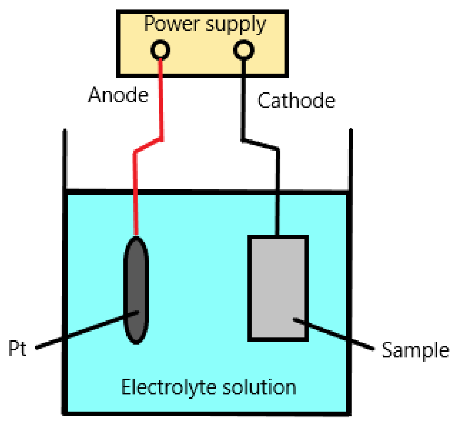
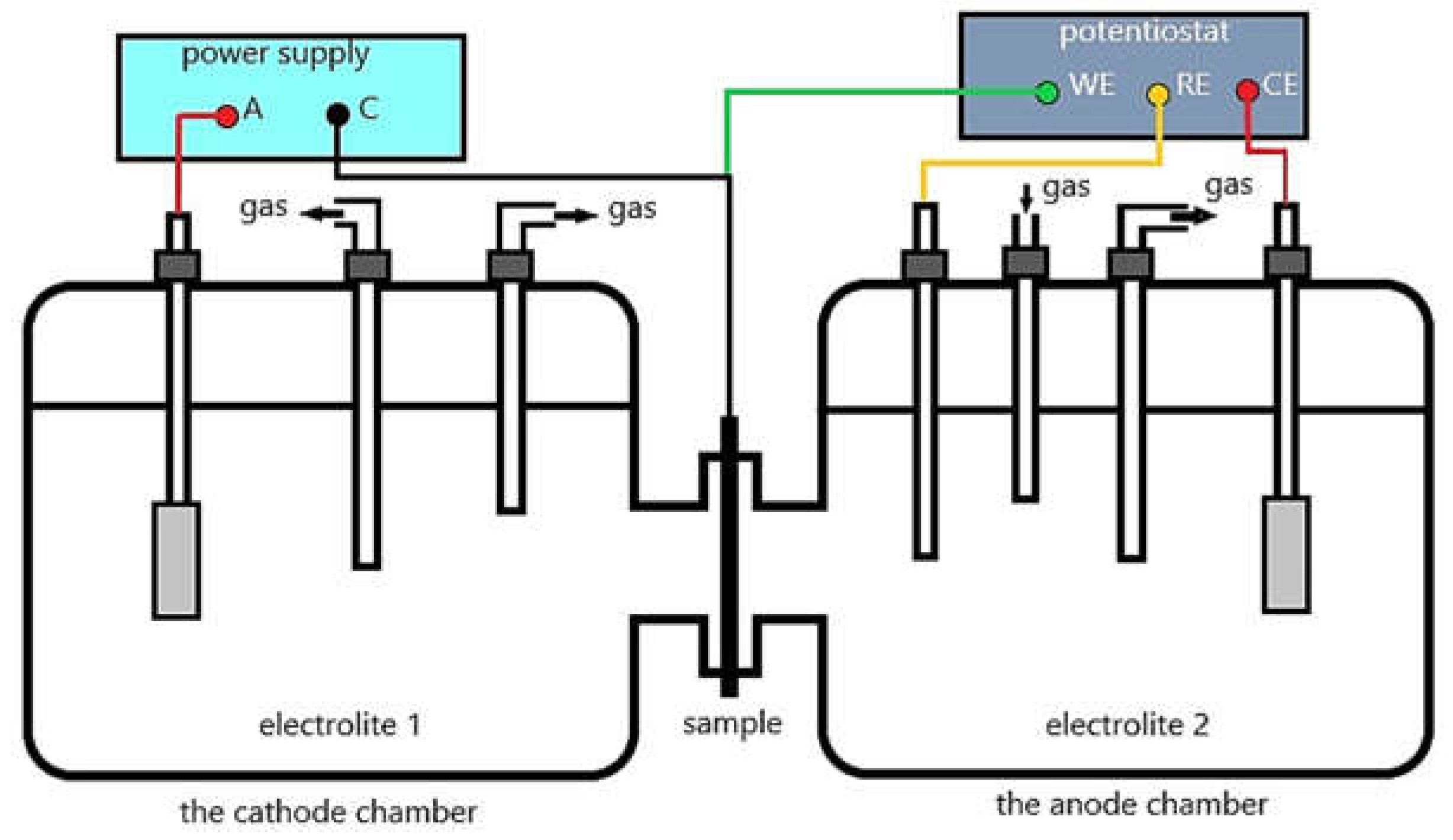
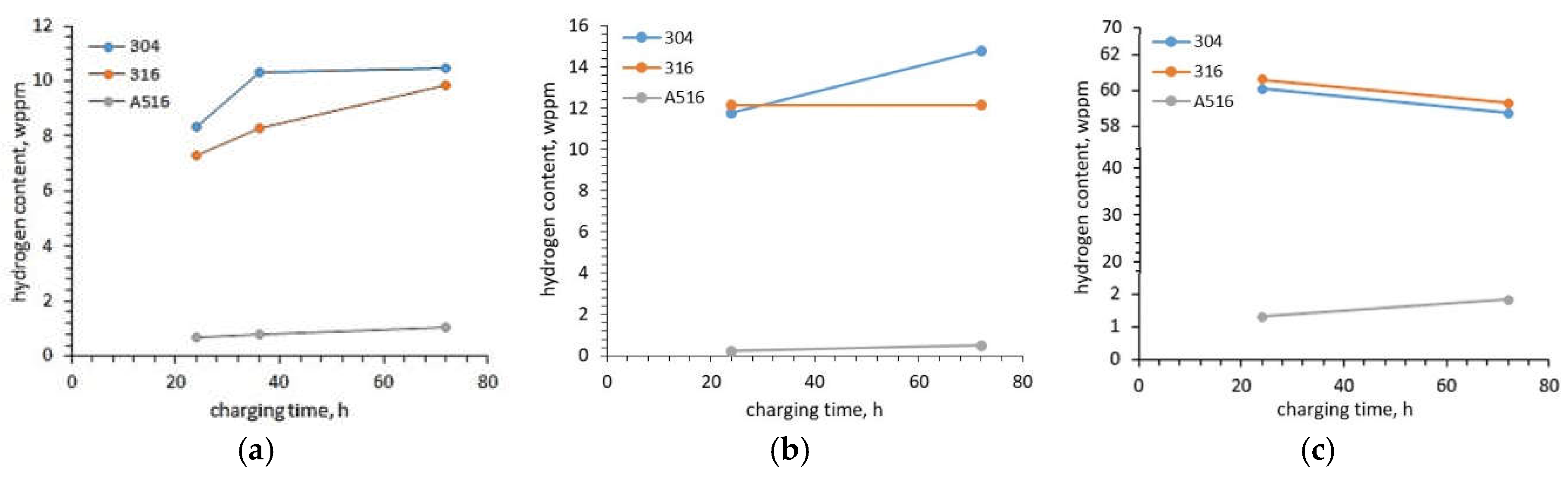
Pałgan et al. [
20] investigated the effect of current density, charging time and charging temperature on the hydrogen uptake in austenitic 316L, 304L steels and low alloyed A516 steel using cathodic and high-pressure gaseous hydrogen charging. The hydrogen uptakes in austenitic steels were much greater (the order of 7 – 8 wppm (weight parts per million)) than in low alloyed ferritic-perlitic steel (the order of 0.7 wppm). Considering that austenitic steel has FCC structure and A516 steel has BCC structure, the reason was the size of the crystallite voids. An increase in current density from 20 mA/cm
2 to 100 mA/cm
2 increased the total hydrogen uptake in 304L steel from 8.36 wppm to 8.68 wppm (3.83%). In the case of 316 L steel, it had a much lower impact and the total hydrogen uptake increased only from 7.28 wppm to 7.34 wppm (0,82 %). In opposition to the total hydrogen uptake, the trapped hydrogen uptake decreased by 11.85 % for 304L steel and 9.5 % for 316L steel. In the case of A526 steel, the total hydrogen uptake decreased from 0.69 wppm to 0.66 wppm (4.35 %) and also the trapped hydrogen uptake decreased. This decrease reached 15.4 %. A much bigger effect on the increase of the hydrogen uptake had a charging time and electrolyte temperature. With an increase in charging time from 24 h to 72 h, the total hydrogen uptake increased by 25.1 %, 35 % and 53.6 % for 304L, 316L and A516 steels, respectively. Although the greatest increase was observed for A516 steel, the total uptake for this steel was the lowest (only 1.06 wppm after 72 h of charging compared to 10.31 wppm for 304L steel). In the case of gaseous charging, the difference in hydrogen uptake in the tested steels was even bigger. For example, charging at a pressure of 200 bar and temperature of 180
oC in pure H
2 for 72 h caused the total hydrogen uptake in A516 steel was 0.49 wppm, while in 304L and 316L were 14.81 wppm and 12.17 wppm, respectively. Performing the charging at 360
oC, the hydrogen uptake was 1.83 wppm, 58.73 wppm and 59.28 wppm, respectively. The results obtained by Pałgan et al. [
20] showed that gaseous hydrogen charging, especially at 360
oC, is much more effective compared to cathodic hydrogen charging (
Figure 3). One of the causes can be higher charging temperature.
Regardless of the research on the influence of hydrogen charging conditions on its content in materials with different crystallographic lattices, another important question is how such a specific level of hydrogen content affects the strength properties. In other words, whether, for example, the content of 1 wppm of hydrogen in the BCC lattice causes correspondingly smaller negative effects than 10 wppm of hydrogen in the FCC lattice. The effect of hydrogen content in the low-alloyed high-strength steel with structure on HE was studied by Takai and Watanuki [
8]. Hydrogen was charged in an aqueous solution of 20 mass% NH
4SCN at the temperature of 50 °C for 24 h. The hydrogen content increased to 3 wppm in steel, which after austenitizing at the temperature of 950 °C for 15 min was transformed isothermally in a lead bath at the temperature of 350 °C for 30 min. This thermal treatment led to the formation of a ferrite and bainite structure. In the case of the steel after transforming in a lead bath at the temperature of 550 °C for 30 min, then cold-drawing for 85 % reduction (true strain: 1.91), which caused the creation of tempered martensite, the hydrogen content increased to 4 wppm. Compared to the results achieved by Pałgan et al. [
20], who also tested low-alloyed steel, the content of hydrogen was much greater. The maximum stress and plastic elongation in the SSRT tests of steel after isothermal treatment at 350
oC decreased by 14 % and 82 %, respectively, with increasing immersion time, in opposition to the steel treated at 550
oC, whose maximum stress and elongation did not change. This shows that the hydrogen content cannot be the only parameter suggesting an expected reduction in elongation, but the material structure must also be taken into account.
In the case of X100 pipeline steel [
4], which is a low-alloyed steel with a heat treatment-dependent structure, the tensile strength in the hydrogen-charging SSRT tests at a strain rate of 1.12 x 10
-6 s
-1 remained nearly unchanged, regardless of the heat treatment applied, whereas the elongation and reduction-in-area decreased. The level of this decrease varied depending on the steel state, which also affected the diffusible H concentration. The biggest decrease in elongation (38.6 %), due to HE, was achieved for the steel after hot-rolling at 1100
oC with an average grain size of 28.7 μm. Steel in this state had the biggest concentration of diffusible H (0.46 ppm). Austenitization at 1000
oC for 3 h and cooling in water at a cooling rate of 600
oC/s after the hot-rolling process resulted in a grain size of 34.6 um, a diffusible H concentration of 0.22 ppm and a reduction in elongation by 33.8% while cooling in air at a cooling rate of 20
oC/s after austenitization resulted in a grain size of 30.6 μm, the diffusible H concentration of 0.19 ppm and the reduction in the elongation by 25.9 %. Considering that the structure of this steel was the same after the hot-rolling process and after cooling in the air and composed of ferrite, martensite and austenite, the grain size, and especially high-angle grain boundaries affected the diffusible H concentration and the reduction in elongation.
3.2. Nickel Alloys
Nickel has a face-centered cubic (FCC) crystal lattice similar to austenitic steel but a density slightly higher. Nevertheless, due to good strength and corrosion properties, nickel alloys are used in the oil and gas industry, where they are subjected to high pressure, high temperature and highly aggressive environments, e.g. corrosive gases containing large amounts of H2S. Such environments cause hydrogen to enter structural elements. For this reason, the study of HE in nickel alloys is very important.
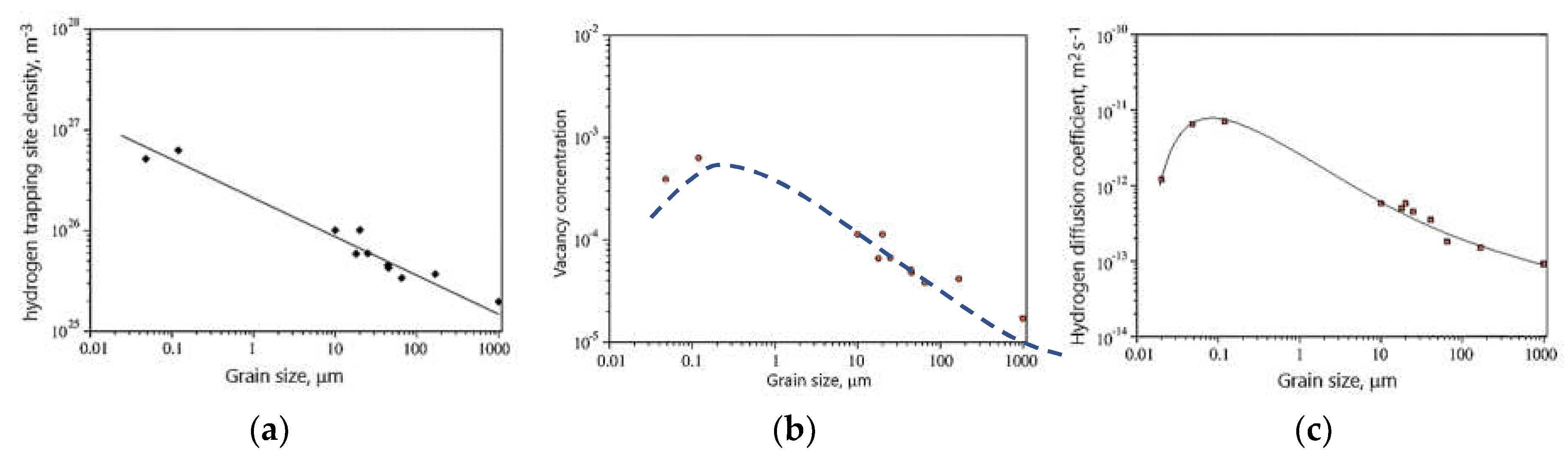
Due to the numerous applications of nickel alloys in industry, where they are exposed to hydrogen entry, the first stage of HE research concerned the study of the influence of structure, i.e. grain size, on hydrogen diffusion and its trapping sites. Oudriss et al. [
46] investigated the effect of grain size in pure nickel on hydrogen trapping sites and hydrogen diffusion. For this purpose, they used the technique of Devanathan and Stachurski. Initially, they investigated the effect of grain size on GB and obtained that the increase in grain size from 20 nm to 168 m caused the decrease in GB densities, which are exponential in nature. The electrochemical hydrogen permeation test showed the density of hydrogen trapping size, vacancy concentration and diffusion coefficient were related to the grain size (
Figure 4). With increasing grain size, i.e. decreasing GB density, trapping site density decreased (
Figure 4a). In the case of vacancy concentrations and diffusion coefficients, a threshold value of grain size was noted at which they reached the greatest value (
Figure 4 b and c). Comparing the correlation between grain size and vacancy with the correlation between grain size and diffusion coefficient, a correlation between diffusion coefficient and vacancy density is seen: the effective diffusion coefficient increased with increasing vacancy density. They found that the acceleration of hydrogen diffusion along grain boundaries was mainly due to high-angle boundaries. The grain boundaries with low misorientation are preferential areas for hydrogen segregation. Moreover, hydrogen promoted the formation of vacancies around the GBs.
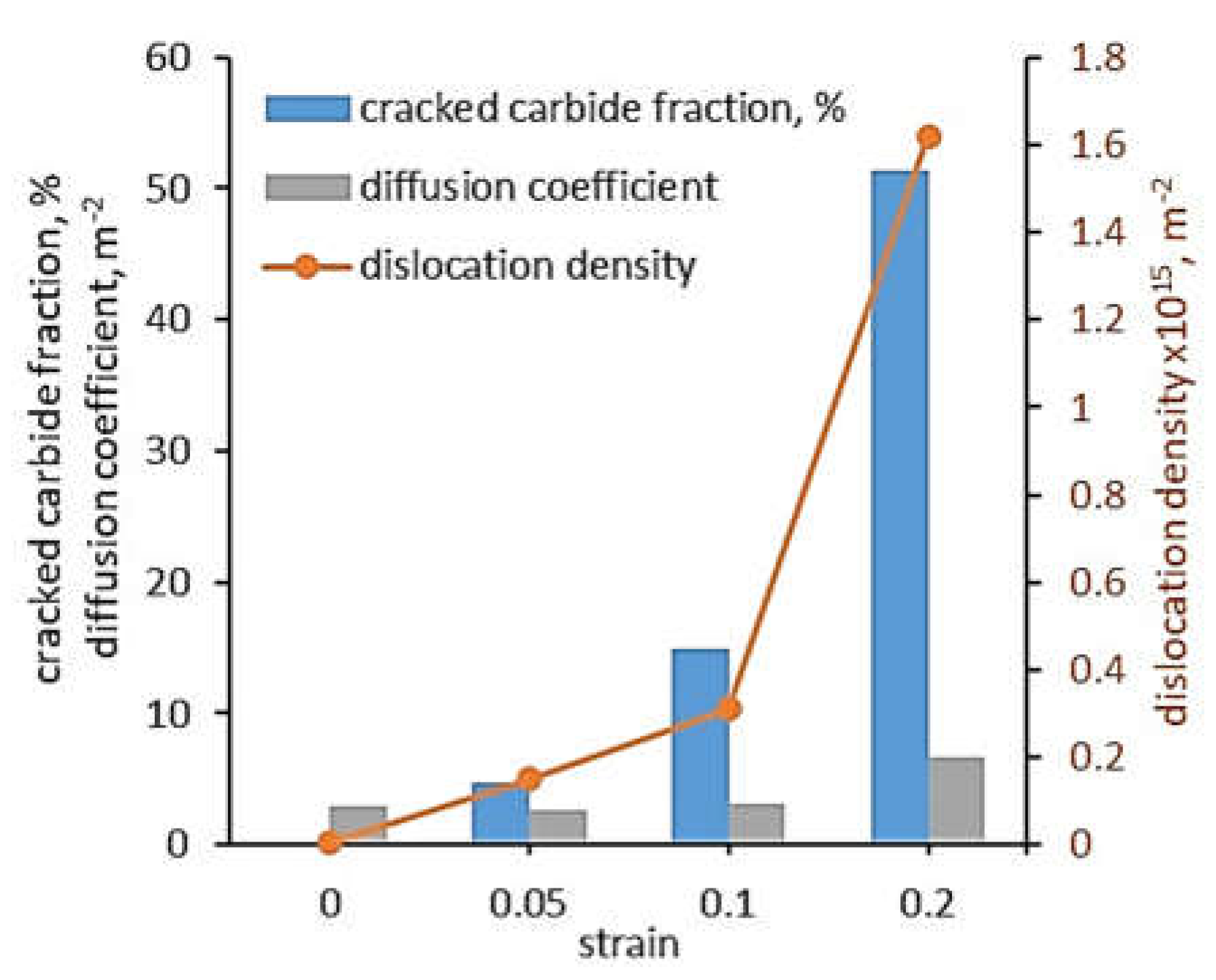
Since in industrial applications the material is subjected to stresses that can cause deformation, Lu et al. [
47] investigated the effect of plastic deformation of 625 alloy, i.e. strain, on dislocation density and finally the effective diffusion coefficients (D
eff). The alloy was pre-strained to three strain levels: ε = 0.05, 0.1 and 0.2 and then was hydrogen charged using a Devanathan-Stachursky permeability cell. In the oxidation cell, 0.1 M NaOH was used, while 0.2 g/L thiourea was added to the charging cell to promote hydrogen adsorption. The pre-straining caused cracking of the carbides which precipitated along the grain boundaries and increased the dislocation density, which finally increased the effective diffusion coefficient (
Figure 5). At a strain of 0.05, 4.47% of the carbides were cracked and the dislocation density was 0.15 x 10
15 m
-2. The permeation test showed that D
eff was 2.93 m
2/s. The increase in strain to 0.1 increased the cracked carbides to 0.31, dislocation density to 0.31 x 10
15 m
-2 and D
eff to 2.65 m
2/s. Thus, a two-fold increase in strain caused twice the increase in dislocation density and a three-fold increase in cracked carbides, but had little effect on D
eff. A further two-fold increase in strain to ε=0.2 resulted in a five-fold increase in dislocation density, a three-fold increase in cracked carbides and a two-fold increase in diffusion coefficient.
The effect of hydrogen on mechanical properties was investigated by Lu et al. [
5]. They tested two Ni-based superalloys: 718 and 725 alloys, which differed mainly in the content of iron: 718 alloy has 19.14 wt.% Fe and 725 has 10.1 wt.% Fe. Both alloys were subjected to heat treatment: 718 alloy was aged at 782
oC for 6.5 h followed by air cooling and 725 alloy was aged at 732
oC for 8 h and 621
oC for 8 h followed by air cooling. After hydrogen charging in a mixture of glycerol and H
3PO
4 for 18 h at a cathodic current density of 15 mA/cm
2 at 75
oC. Hydrogen desorption spectra for both alloys showed that hydrogen was trapped at precipitates, GBs, and δ phase (Ni
3Nb). Ultimate tensile strength (UTS) in the SSRT tests conducted at a strain rate of 2 x 10
-5 s
-1 was reduced by 10% and 31% and total elongation was reduced by 66.1% and 87.3% for 718 and 725 alloy, respectively, compared to these alloys in hydrogen-free condition. They found that local increases in stress and strain concentration at the intersections of dislocation slip bands attracted hydrogen to these sites and promoted the formation of dislocations and vacancies, which ultimately contributed to the formation of microvoids and was responsible for the primary transgranular cracks. The intergranular cracks in alloy 718 were attributed to the slip localization at the triple junctions of GB, highly disoriented GB and δ-decorated GB. In the presence of hydrogen, the formation of microcracks along the disjoint interfaces between δ-precipitate and matrix becomes easier under the HEDE mechanism. As a result, the hydrogenated alloys exhibited mixed mode fracture: brittle and ductile, whereas the hydrogen-free alloys exhibited ductile mode fracture. The brittle fracture was in the form of river patterns and ridges. Intergranular cracking occurred along the GBs as well as phase boundaries, but the most brittle region was dominated by transgranular cracking.
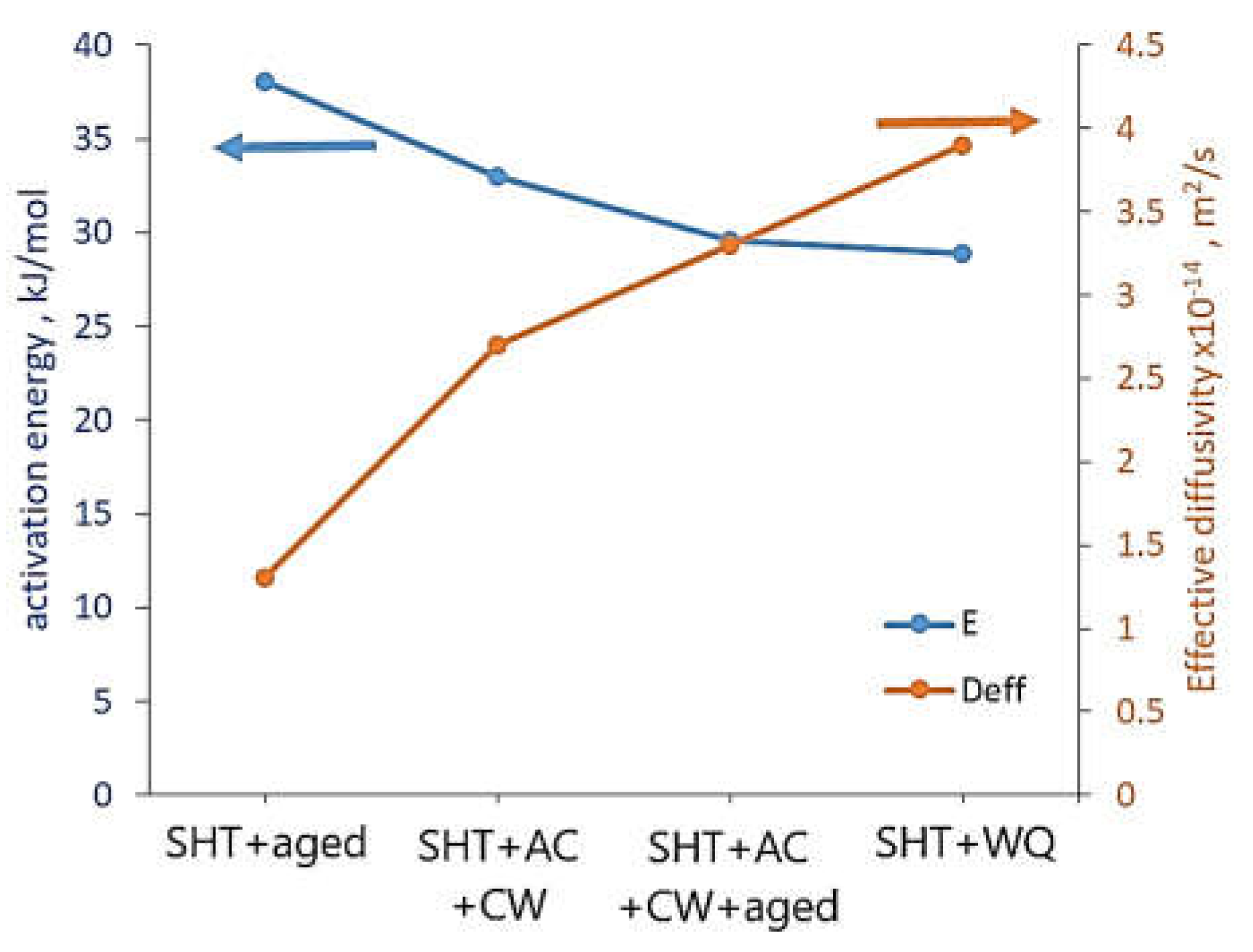
Nickel alloy, which is especially widely used in the oil and gas industry, is Monel®. Monel® K-500 is a nickel-copper (64% Ni–30% Cu–3% Al, wt.%) alloy resistant to stress corrosion cracking (SCC) in various natural environments. In addition, an increase in the operating temperature causes a small decrease in mechanical properties. In the case of the alloy in the precipitation-hardened condition, the yield strength drops from 670 MPa to 570 when the temperature increases from 20
oC to 500
oC. Ai et al. [
48] investigated the effect of the isothermal treatment on hydrogen uptake and diffusivity. The alloy was solution heat treated (SHT) and aged (SHT + aged), SHT and air-cooled (SHT + AC), SHT and AC and cold-worked (SHT + AC + CW), SHT and AC and CW and aged (SHT + AC +CW + aged), and SHT and water-quenched (SHT + WQ). The activation energy for H diffusion was in the range of 28.9 ± 1.1 – 38.1 ± 3.6 kJ/mol, and room temperature effective H diffusivity ranged from 0.9 to 3.9 x 10
-14 m
2/s, depending on the alloy condition (
Figure 6). The lowest activation energy and the highest effective diffusivity had Monel K-500 in the SHT+WQ condition while the biggest activation energy and the lowest effective diffusivity in the SHT + aged condition (28.9 + 1.1 and 3.9 x 10
-14 vs. 38.1 + 3.6 kJ/mol and 1.3 x 10
-14 m
2/s, respectively). They attributed the higher activation energy in the aged material compared to the solid solution condition to the transport barriers resulting from H trapping in the precipitates. for SHT, SHT + aged, SHT + AC + CW and SHT + AC + CW + aged Monel K-500.
Harris and Burns [
49] also investigated Monel K-500 after isothermal heat treatment, but they were interested in susceptibility to cracking in a hydrogen environment. The alloy was solution-treated at 950
oC for 1 h followed by water quench and aged at 650
oC for 0, 0.5, 5 and 50 h followed by water quench. This heat treatment increased yield stress, tensile strength and Young’s modulus. However, the biggest mechanical properties were achieved after ageing for 5 h. The heat treatment had little effect on grain size and a fraction of Σ3 and Σ9 grain boundaries, but the radius of precipitations increased from 3.34 nm to 11.22 nm with increasing time of ageing from 0.5 h to 50 h. The susceptibility to cracking was investigated in four environments: dry N
2 gas and full immersion in aqueous 0.6 M NaCl electrolyte at applied potentials of -1000, -1100, and -1200 mV
SCE. The crack growth rate of the non-aged alloy increased nearly linearly on a logarithmic scale with increasing stress intensity (K
J) for potentials of -1100 and -1200 mV
SCE. In addition, a higher rate of crack growth was obtained for the higher potential (-1100 mV
SCE). In the case of the aged alloy in all conditions, the highest rate of crack growth was obtained for the lowest potential (-1200 mV
SCE), and with increasing ageing time the crack growth rate at K=45 MPa √m decreased. This was because with increasing negative potentials (and therefore higher overpotentials for hydrogen production), additional diffusive hydrogen was formed, which increased the crack growth rate. Fractography of the alloy aged for 0.5 h showed that the intergranular - hydrogen environment-assisted cracking (HEAC) occurred at all applied potentials. In the case of the alloy aged for 5 h, intergranular cracking attributable to HEAC occurred at -1200 and -1100 mV
SCE. However, this alloy tested at -1000 mV
SCE showed no HEAC. In the case of testing the alloy aged for 50 h, a mixed intergranular -transgranular HEAC fracture morphology was observed only for testing at -1200 mV
SC E.
3.3. Aluminium Alloys
Aluminium has a face-centered cubic (FCC) crystal lattice and very low density (2.7 g/cm
3). Due to the low density of aluminium alloys, they play an important role in many applications, especially where the weight of construction is crucial, e.g. in transport as well as in hydrogen energy and the aerospace industry [
15]. Pure aluminium is soft and has low strength. To increase it, alloying elements such as copper, magnesium, silicon, manganese, zinc, zirconium, nickel, caesium, cobalt and iron are added. This increase in strength is mainly due to precipitation hardening. Therefore, when discussing the hydrogen uptake in aluminium alloy, attention should be paid to the influence of precipitates of intermetallic phases.
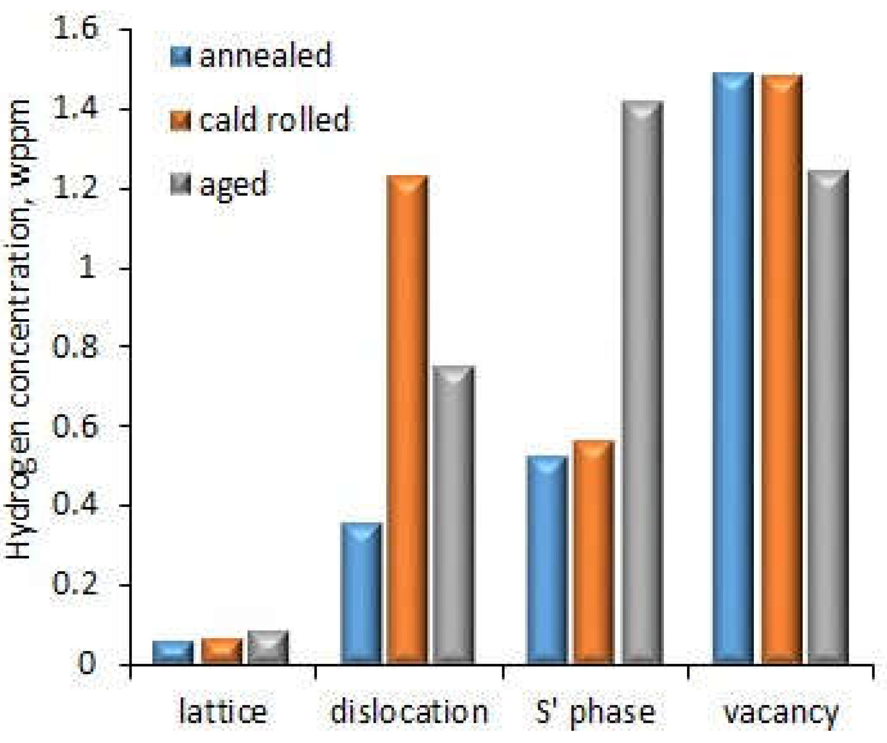
The influence of the structure and types of structural defects in Al-Cu-Mg alloy after different treatments on the hydrogen trap sites were investigated by Safyari et al. [
36]. The Al-Cu-Mg alloy was subjected to three different treatments: annealing at 495
oC for 1 h and quenched in water, called rolling after annealing to reduce the thickness by 20% and ageing at 190
oC for 9 h, which resulted in different densities of dislocations, vacancies and precipitates. Hydrogen was introduced during SSRT testing at a strain rate of 1.67 x 10
-7 s
-1 at room temperature in humid air controlled to 90% relative humidity. In the case of the alloy after annealing, no dislocations and precipitations in the local area adjacent GBs were observed. The cold rolling treatment increased dislocation density near the GBs. Ageing led to precipitating the S’ (Al
2CuMg) phase in GBs and inside the grains. The HE susceptibility (HES) indexes calculated as the reduction in elongation due to testing in the different environments were 1.6%, 21.2% and 0% for the alloy after annealing, cold working and ageing, respectively. This means that cold rolling highly reduced resistance to HE in contrast to ageing which did not affect it. This shows that cold rolling causing high dislocation density at GBs had the biggest impact on HE. Thermal desorption spectroscopy (TDS) at a heating rate of 200
oC/h showed that in addition to dislocations, vacancies, S' phase and crystallographic lattice were the other sites of hydrogen trapping. Hydrogen concentration at different trap sides is shown in
Figure 7. The most hydrogen was trapped in vacancies and the least in the crystallographic lattice. The effect of vacancies decreased in the case of the aged alloy, when the S’ phase precipitated, which contributed to more hydrogen being trapped there. Also in the case of dislocations, in the alloy after cold rolling, where there was a high density of dislocations, more hydrogen was trapped there. This shows that the effect of individual hydrogen trapping sites was dependent on their density in the alloy structure. Considering that ageing and second-phase precipitation are a natural process of Al-Cu-Mg alloys, these results showed the high resistance of such alloys to HE. On the other hand, since cold rolling is used for increasing endurance properties (tensile strength), aluminium alloys should then be artificially aged to reduce the risk of HE.
An indentation test for studying the effect of hydrogen charging conditions on the mechanical and tribological properties of aluminium alloy was used by Georgiou et al. [
16]. The tested alloy was 5754 aluminium alloy (3.2 wt% Mg, 0.5 wt% Mn, 0.4 wt% Si, 0.4 wt% Fe, 0.1 wt% Cu and Al balance). Hydrogen charging was done by cathodic polarization in a 3 M HCl aqueous solution without poison as a hydrogen recombination inhibitor at room temperature. Graphite electrodes were used as anodes. The current densities were in the range of 25 up to 300 mA/cm
2 for a charging time of 2 h. Due to the lack of poison, the uptake of hydrogen was limited. Hydrogen content in the surface of hydrogen-charged aluminium alloy ranged from 0.2 up to 1 at% hydrogen depending on the cathodic current density. The indentation tests showed that the hardness increased from 0.94 GPa for uncharged alloy to 1.17 GPa for the current density of 75 mA/cm
2. Further increase in current density resulted in lower hardness increase. In addition to hardness, elastic modulus also increased. This caused the resistance to plastic deformation to decrease compared to uncharged alloy. The lowest decrease was obtained for the alloy charged at a current density of 75 mA/cm
2 (5.5 %), whereas the biggest was for charging at a current density of 150 mA/cm
2 (17.9 %). Despite the hardness increase, the wear depth in sliding testing also increased compared to uncharged alloy and the biggest increase in wear depth was for charging at a current density of 150 mA/cm
2 (26.5 %).
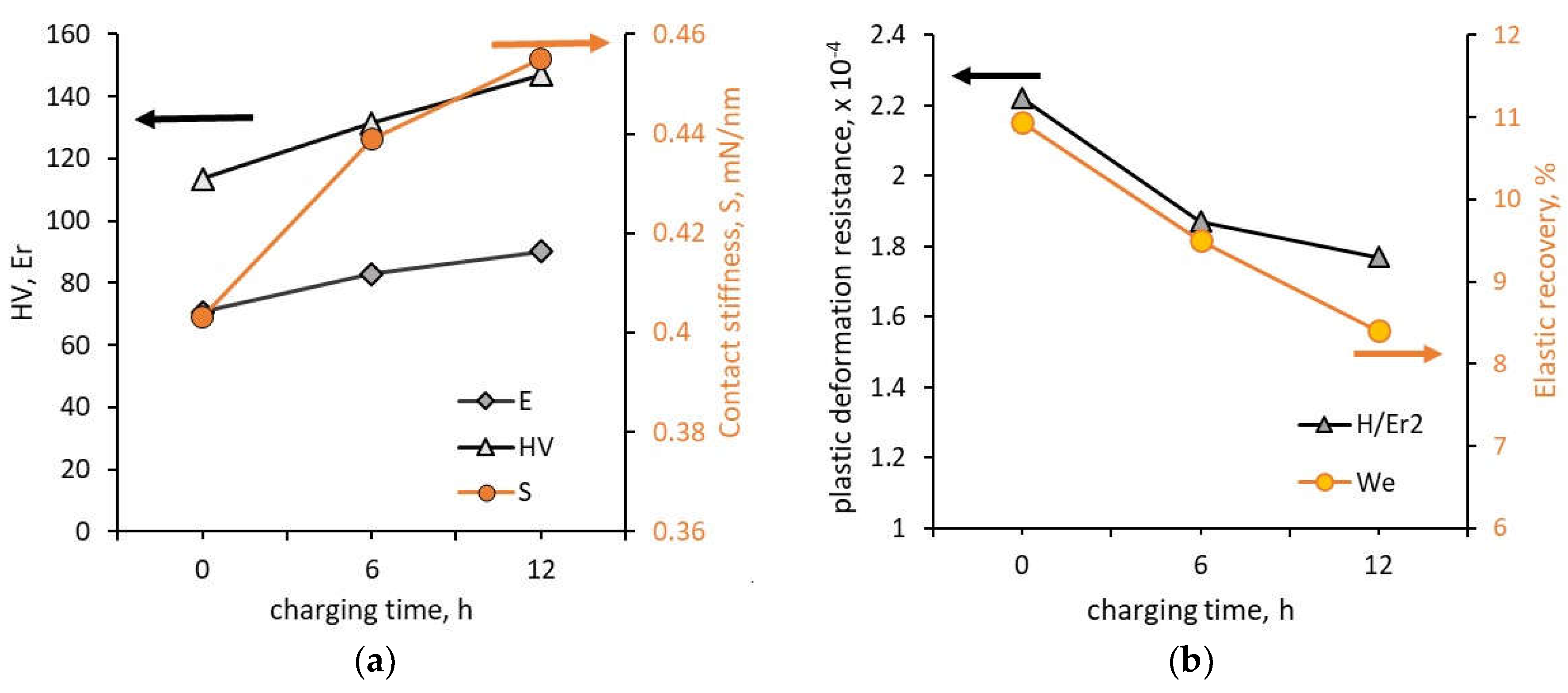
Shin and Kim [
23] also investigated the effect of hydrogen charging time on the mechanical properties of aluminium alloy (0.82 wt.% Mg, 0.31 wt.% Si, 0.44 wt% Fe, 0.18 wt.% Cr, 0.2 wt.% Cu, Al –balance). The hydrogen charging process was performed at the current density of 10 mA cm
−2 in 2 N H
2SO
4 + 1g l
−1 Na
2HAsO
4·7H
2O aqueous solution for 6, and 12 h. The surface analysis with a 3D microscope showed that with increasing charging time the surface roughness increased from Sa = 0.093 μm to Sa = 0.232 μm and this increase was due to the increasing number and size of hydrogen-induced pits. Investigations performed using an indentation tester showed that the contact stiffness, hardness and reduced Young’s modulus increased but resistance to plastic deformation and elastic recovery decreased (
Figure 8). The contact stiffness increased by 12.9 % (from 0.403 mN/nm to 0.455 mN/nm), hardness increased by about 29.7% (from 1.11 GPa to 1.44 GPa), Young’s modulus increased by about 27.5 % (from 70.725 GPa to 90.15 GPa). The resistance to plastic deformation decreased from 10.9 % for uncharged alloy to 8.4 % for 12 h of charging. Shin and Kim [
23] showed that the change in mechanical properties followed the effect of hydrogen on dislocation movement according to the HELP model.
Takano [
50] found that cathodic hydrogen charging of 7075 aluminium alloy (Al-Zn-Mg-Cu alloy) in 1 N H
2SO
4 solution with a current density of 10 mA/cm
2 and 100 mA/cm
2 at 45
oC during SSRT test at a strain rate of 10
-5 s
-1 decreased both the tensile stress and elongation. The tensile stress decreased by 28 % and 34 %, respectively compared to uncharged alloy, whereas the elongation decreased by 57 % regardless of the current density. Thus, the biggest decrease was for the current density of 10 mA/cm
2, further increase in current density did not cause much change.
3.2. Titanium Alloys
Titanium and its alloy have a lower density than steel but higher than aluminium. Their very good strength properties and resistance to elevated temperatures and aggressive environments caused wide application in many branches of industries. In opposition to austenitic steel, nickel and aluminium, titanium has a hexagonal close-packed (HCP) crystal lattice. The main alloying elements are aluminium and vanadium. Depending on the structure, titanium alloys are divided into three main groups: α-phase and near α-phase alloys, e.g. Ti-6Al-2Sn-4Zr-2Mo-0.1Si alloy [
31], α+β-phase alloys, e.g. Ti–6Al–4V alloy [
51], Ti-5Al-5Mo-2V-2Cr-2Sn-2Zr alloy [
52] and β-phase alloys, e.g. Ti–3Al–8V–6Cr–4Zr–4Mo alloy [
53].
The effect of hydrogen content on properties and fracture of α-phase and near α-phase alloys was studied for Ti-6Al-2.8Sn-4Zr-0.5Mo-0.4Si-0.1Y alloy (Ti600) [
30] and Ti-6Al-2Sn-4Zr-2Mo-0.1Si alloy [
31], which are near-α titanium alloys. However, thermal or thermo-mechanical treatment can cause the formation of some amount of β-phase. Ti-6Al-2.8Sn-4Zr-0.5Mo-0.4Si-0.1Y alloy was charged with hydrogen using a furnace at 750
oC and pressure 5 x 10
-4 Pa to which hydrogen was introduced (1l/min) [
30]. This treatment led to the martensitic transformation β−Ti phase → α’’ phase and eutectoid transformation β
H → δ + α phases. Zhang et al. [
30] obtained that with the increase in hydrogen content, the β-phase content increased and the martensitic transformation temperature reduced. Hydrogen improved the stability of the β phase, reduced the critical cooling rate, which is important in many applications and also reduced the characteristic temperature of martensitic transformation. Examination of elongation and flow stress of Ti600 alloy was performed at temperatures ranging between 840
oC and 960
oC and a strain rate of 5 x 10
-4 s
-1 [
30]. Elongation of the alloy without hydrogen charge increased with temperature from 230% to 275%. Hydrogen charging contributed to even higher elongation. At 860
oC, regardless of hydrogen content, elongation was higher than 260%. The maximum improvement (300%) was achieved by the alloy with a hydrogen concentration of 0.2 wt.%. Further increase in temperature caused a decrease of elongation improvement. Moreover, the elongation of hydrogenated alloy did not change monotonically with temperature, first it increased and then decreased. With increasing temperature, the hydrogen content in the alloy, at which the elongation was lower than in the unsaturated alloy, increased. The exception was the alloy with a hydrogen concentration of 0.5 wt.%, whose elongation increased with temperature. The elongation of this alloy reached a maximum value of 335% at 960
oC. Hydrogen also reduced the flow stress compared to the unloaded alloy.
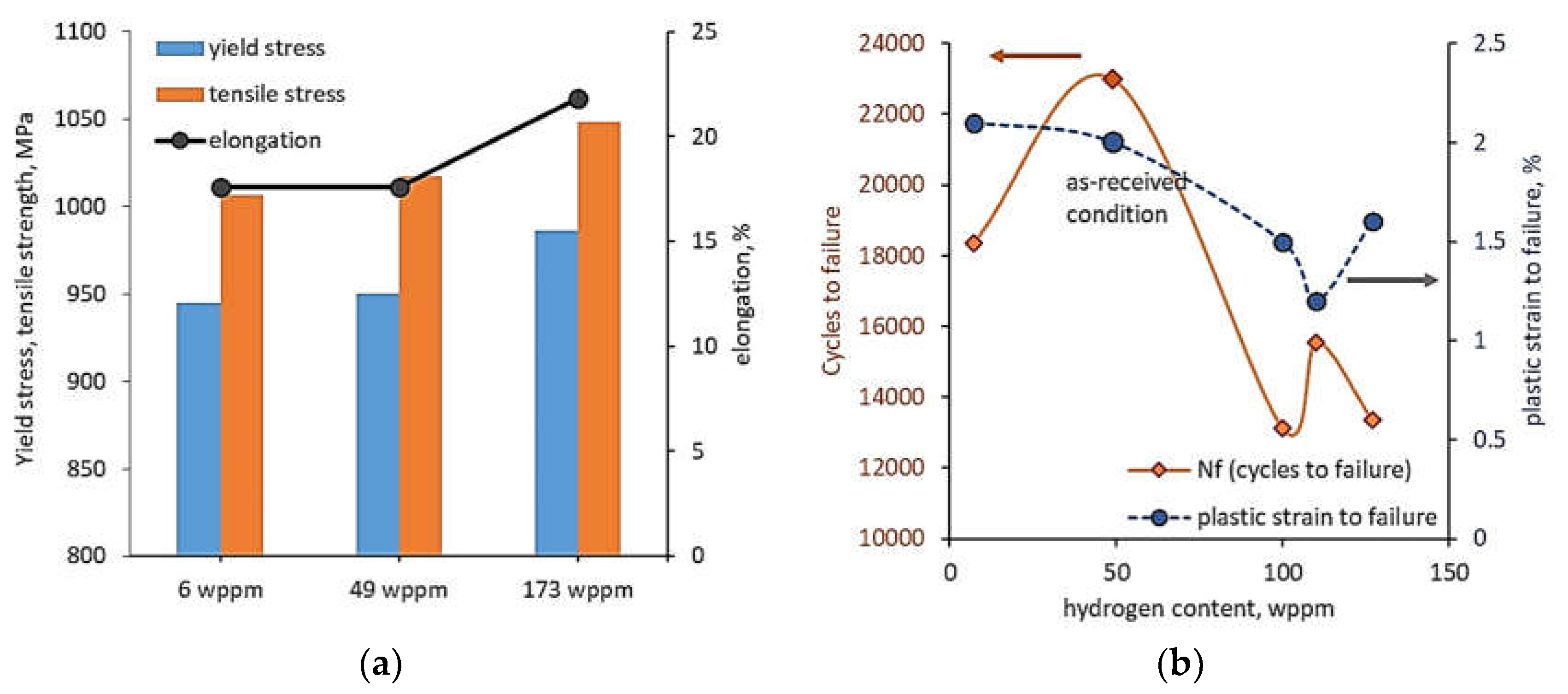
Ti-6Al-2Sn-4Zr-2Mo-0.1Si alloy was subjected to thermo-mechanical processing consisting of forging at 28 °C to ~58% strain, solution heat treatment at 56 °C and air-cooling, then ageing at 593 °C for 8 h and again air-cooling to room temperature [
31]. This treatment resulted in a bimodal microstructure consisting of globular primary α-phase grains (~65 to 70 vol%) and lamellar transformed β-phase regions (~30 to 35 vol%). Then, the Ti-6Al-2Sn-4Zr-2Mo-0.1Si alloy was charged with hydrogen at a temperature of 550–600
oC using the Sievert apparatus [
31]. In order to investigate the effect of hydrogen on mechanical properties, the tensile tests were conducted at room temperature and a strain rate of 1 x 10
-4 s
-1. Additionally, fatigue tests were carried out at room temperature, load ratio R=0, frequency of 0.5 Hz and the maximum stress of 0.95 x yield stress. Similar to the results shown in [
30], the increase in hydrogen content increased elongation. An increase in yield stress and tensile strength was also achieved (
Figure 9a). In opposition to tensile properties, the fatigue tests showed that hydrogen charging decreased both the number of cycles to failure and the plastic strain-to-failure compared to uncharged alloy (
Figure 9b). Thus, fatigue life was reduced despite the improvement in mechanical properties.
The most examined dual-phase ( α + β ) titanium alloy is Ti–6Al–4V alloy. The effect of hydrogen on the cracking of this alloy was investigated by Tal-Gutelmacher and Eliezer [
51]. Lokoshenko et al. [
32] studied the creep and long-term strength of this alloy and Kolachev et al [
33] investigated the fatigue resistance. Similar to Sinha et al. [
31] who tested near a-phase titanium alloys, Lokoshenko et al. [
32] and Kolachev et al [
33] also used the thermo-diffusion method for saturation of Ti – 6Al – 4V alloy with hydrogen. Creep tests showed that with increasing hydrogen content and testing stresses, the steady-state creep rate and threshold creep strain decreased, while the time to fracture increased [
32]. In the case of fatigue tests, the fatigue strength, taken as the stress obtained for 1 x 10
6 cycles, initially increased with increasing hydrogen content but then decreased [
33]. The threshold value of hydrogen content, at which the best fatigue resistance was noted depended on the initial heat treatment of the alloy and the conditions of fatigue tests. Regardless of many factors, the hydrogen content bigger than 0.04% reduced fatigue stress and fatigue life. These results are in line with the studies of Sinha et al. [
31].
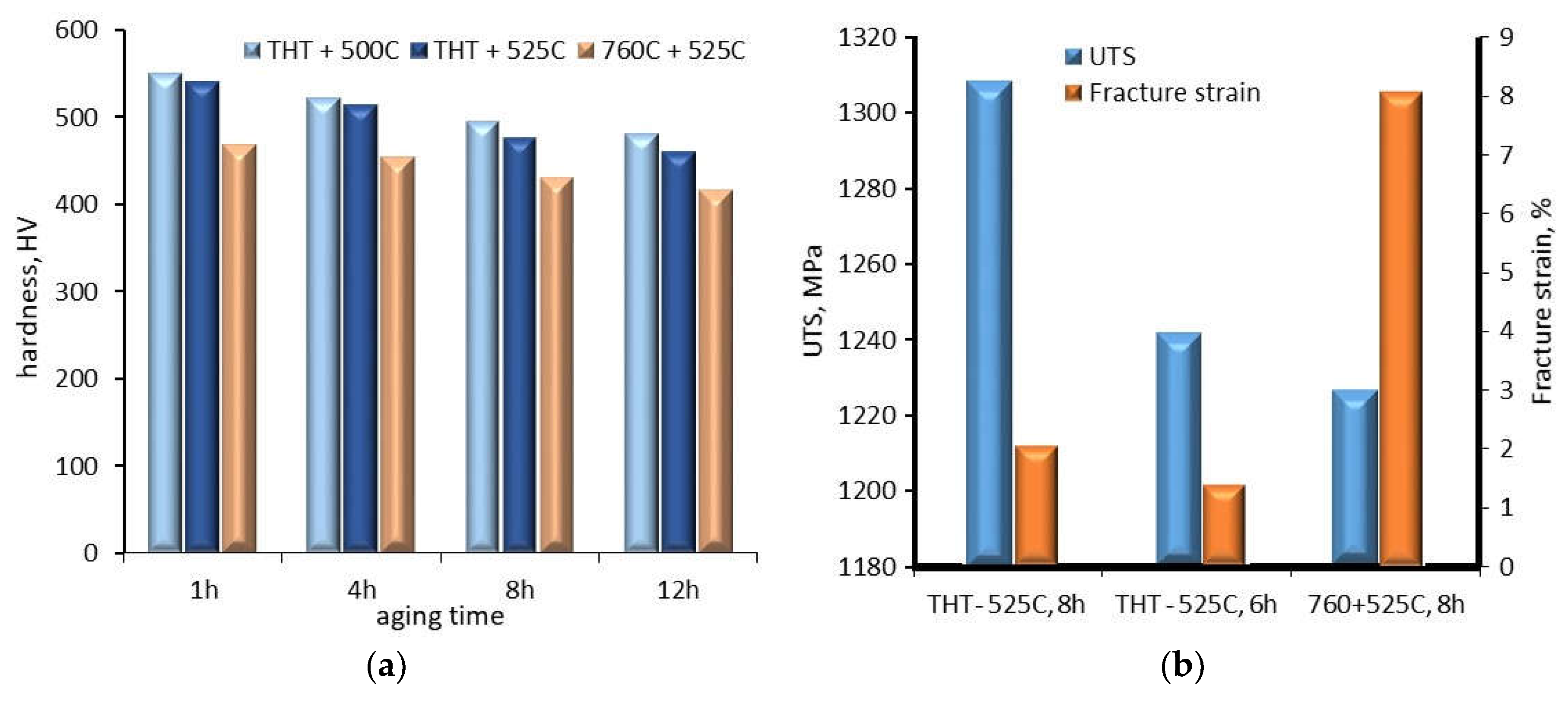
The examples of metastable β phase titanium alloys are Ti 10V–2Fe–3Al (Ti 10-2-3) and Ti–3Al–8V–6Cr–4Zr–4Mo. In the case of Ti 10-2-3 alloy, the influence of hydrogen charging using thermohydrogen treatment (THT, hydrogen enter during the heat treatment at temperatures in the range between 550
oC and 795
oC) on phase stability and mechanical properties (microhardness, ultimate tensile strength and fracture strain) after ageing at different temperatures (500
oC and 525
oC) and times (1 h, 4 h, 8h and 12 h) were investigated [
54]. Initially, the alloy had a structure consisting of the β-phase (BCC Ti) and α
P-phase (HCP Ti). Solution treatment (ST) at 760
oC for 1 h resulted in an increasing volume fraction of the α
P phase grains and the formation of the strengthening α
S phase. Ageing of the alloy at 525
oC for 8 h after ST caused an increase in the volume of the fraction of the α
S phase and the α
GB phase (the soft continuous layer at the grain boundaries of the β phase) and a reduction of the β phase grains to about 5 μm. The effect of hydrogen on the structure of the alloy depended on the value of hydrogen uptake. At hydrogen intake up to 32 at.%, hydrogen was dissolved mainly in the β phase. This was due to the fact that hydrogen is a β-phase-stabilizing alloying element. As a consequence, the alloy consisted of α and β phases. When the hydrogen content exceeded 32 at.%, areas with two-phase (β+hydride) and three-phase (β+α+hybride) structures were formed. It should be noted that the hydrides formed in these structures differed in chemical composition, stoichiometry and crystal structure. The hydride content increased with increasing hydrogen concentration in the alloy. Ageing of the alloy reduced the volume fraction of the α
S phase, and increased α
GB-phased layers and the size of α
GB-phase precipitates. Hardness measurements showed that hydrogen increased the hardness of the alloy, but ageing decreased it. The decrease in hardness depended on the ageing temperature and time (
Figure 10a). For example, for an increase in aging temperature from 500
oC to 525
oC and with an aging time of 1 hour, the hardness decreased by only 10 HV. In the case of aging at 525
oC for 12 hours, the decrease in hardness compared to aging for 1 hour was 80 HV. In comparison, ageing the alloy for 12 hours after ST at 760
oC resulted in a 52 HV decrease in hardness. In contrast to hardness, increasing the ageing time increased the UTS and fracture strain (
Figure 10b). Comparing the UTS and fracture strain of the alloy after ST at 760
oC and ageing for 8 hours and the alloy after hydrogen charging and ageing for 8 hours, there is a significant decrease in UTS and an increase in fracture strain.
Ti–3Al–8V–6Cr–4Zr–4Mo alloy after hydrogen charging at constant pressure for 8 h at 350
oC (623 K) and ageing at 482
oC for 28 h was investigated using TEM, XRD and SSRT tests [
53]. The as-received alloy in the quenched condition had β-phase grains with an average diameter of 26 μm. Ageing in a vacuum for 28 hours at 482
oC (755K) followed by air cooling resulted in the formation of HCP α-phase precipitates in a BCC β-phase matrix. The volume fraction of the α-phase was approx. 34 %. Charging with hydrogen to a concentration of 38 at.% did not change the phase composition and the alloy consisted only of α- and β− phases. Further increase of hydrogen concentration in the alloy resulted in the appearance of FCC δ-hydrides. The fcc δ-hydrides were formed in the hcp α-phase precipitates, while hydrogen remained in solid solution in the β-phase at its maximum concentration. As hydrogen concentration increased, the lattice parameter of β-phase also increased, however, for hydrogen concentration up to approx.. 20 at%, the lattice parameter was lower than initial, in the alloy in as-received condition. Moreover, for hydrogen concentration bigger than approx.. 35 at%, the lattice parameter rapidly increased. SSRT tests showed that hydrogen concentration up to approx. 3.5 at%, the elongation (failure strain) was in the range of 15 - 20%. A further increase in hydrogen concentration rapidly reduced the elongation to approx. 3 %. Thus, the problem of embrittlement affected the alloy with a hydrogen concentration above 3.5 at%.