
Submitted:
17 December 2024
Posted:
18 December 2024
You are already at the latest version
Abstract
The high penetration and uncertainty of renewable energy sources, such as wind, in modern power systems make traditional automatic generation control (AGC) methods more challenging. In order to improve the frequency stability of the power system under the high proportion of wind power penetration, the inherent fast response characteristics of energy storage can be adjusted with the system in both directions with each other, but the storage power will be insufficient when the state of charge (SOC) is close to the upper and lower limits, at this time, it is difficult to take into account both the state of charge protection of the energy storage and the effect of frequency regulation. Based on the purpose of testing the grid frequency modulation (FM) performance and efficient use of frequency modulation resources, this paper proposes a wind power high penetration system frequency modulation control strategy considering storage state of charge, by constructing a two-zone automatic generation control system model containing wind power, using an improved adaptive ocean predator algorithm to optimise the frequency modulation responsibility allocation method in real time, and formulating a real-time management scheme for storage state of charge. Finally, the different control strategies are compared and analysed by MATLAB/Simulink under different loads and wind speeds, and their effectiveness is verified by the frequency offset and state of charge offset, so as to optimise the effect of frequency modulation while maintaining the state of charge of energy storage.
Keywords:
energy storage
; wind power
; state of charge
; automatic generation control
; lithium-ion batteries
1. Introduction
In recent years, wind power is one of the clean energy sources with the easiest development, the widest application and the most mature technology, and the increasing penetration of wind power in the new power system has brought new challenges to the power system frequency regulation, and put forward new requirements for the wind power frequency regulation capability[1]. In addition, due to the intermittency and uncontrollability of wind energy, wind power generation has the uncertainty of power output, and the impact of wind turbine power electronic equipment on the power grid leads to the decoupling of rotational speed and system frequency, and the decrease of system inertia level, which negatively affects the dynamic active balance of power generation and load of the power system and then threatens the safe operation of the power system. In order to reduce the impact of large-scale access of new energy on the pressure of grid frequency regulation, the traditional frequency regulation unit is unable to accurately execute automatic generation control automatic generation control(AGC) commands due to its slow response speed and low control accuracy, resulting in the phenomena of speed lag, speed reversal, and speed deviation, which can't satisfy the demand for secondary frequency regulation under the grid-connected power system. Energy storage has precise, fast and flexible power response capability, and its participation in frequency regulation can improve the frequency response speed of wind turbines. The use of energy storage systems to participate in frequency regulation has become a means of secondary frequency regulation and control of power systems, including wind power, and has been widely used[2,3].
In view of this problem, many scholars have carried out in-depth and extensive research around this field. Large-scale wind turbine grid-connected wind farms are required to have a primary frequency regulation capability, wind power primary frequency regulation is mainly achieved by using the wind turbine's own power, including rotor kinetic energy frequency regulation and power back-up frequency regulation[4,5,6,7]. The former rotor kinetic energy FM capability is limited, through the virtual inertia control, sag control and integrated inertia control to achieve; the latter uses load shedding control, but at the expense of fan power, can not maximize the power generation benefits. Literature [8] investigated the effect of wind power participation in frequency modulation (FM) on AGC system parameters, and the results show that the dynamic frequency characteristics of the grid containing wind power are closely related to the total inertia time constant H of the power system. Therefore, it is crucial to clarify the correspondence between wind power uncertainty and H and its impact on conventional load frequency control. Literature [9] proposes that the variation of the equivalent virtual inertia time constant of a wind turbine can be expressed as a function of wind speed, rotor speed, or unit output, that variable-parameter virtual inertia control affects the effective energy storage of the unit, and that the variation of the wind turbine's virtual inertia time constant He alters the total inertia time constant H of the power system, which in turn alters the system model parameters. To address the above problems, literature [10] proposes a variable parameter active power compensation strategy, which adjusts the active power parameters in the strategy by judging the range of frequency deviation changes, but the compensation strategy does not directly reflect the changes in the system model when the uncertainty changes.GLOE et al. address the problem of integrated inertia of wind turbines with variable parameters in gusts and low wind speeds, and propose to make the inertial constants proportionally adjusted to the rotational speed, and to design a variable H controller[11]. proportional regulation, and design a variable H controller so as to improve the stability of power systems with low inertia. However, when uncertainty wind power affects the parameters of the AGC system containing wind power, dynamic control adjustment of the controller is the key to solve the problem.
Literature [12] proposes a fuzzy control strategy-based method for frequency regulation of battery energy storage system assisting the grid AGC, using the regional control deviation and its rate of change as inputs, and outputting the reference value of power change of the battery after the calculation within the fuzzy controller. Literature [13] proposed a control strategy for battery coordinated wind turbines and conventional units to participate in the system AGC, using the state of charge (SOC) of the battery as a feedback signal to determine the participation status of each FM resource, but it did not manage to give a clear basis of judgement on the degree of participation of each resource. Literature [14] combined the area control error (ACE) and area regulation requirement (ARR) allocation model, analysed the grid frequency characteristics through the principle of sensitivity, and then combined with the dynamic FM capacity index, proposed the energy storage battery control strategy. Literature [15] proposes a wind-storage joint optimization operation strategy, but its optimisation objective only focuses on the maximum total return of the wind-storage power plant, and does not take into account the system's FM capacity and the constraints on the SOC of the energy storage system. The above literature mostly verifies the effectiveness of the FM control strategy with constant wind speed, ignoring the random volatility of wind speed and the impact of load randomisation on the system frequency, and in addition, the charge state of the energy storage is not fully taken into account in the AGC FM process, and the lack of effective power management may easily result in the over-utilisation of the energy storage, which seriously threatens the stability and reliability of the FM operation.
In summary, this paper proposes a wind power high penetration system FM control strategy considering energy storage SOC, comprehensively considering the wind speed and load random changes in different FM conditions, the wind turbine to provide the inertia support needed for FM, and formulating a real-time management scheme for energy storage SOC, which reduces the frequent actions of the storage system and the number of deep charging and discharging times, and can effectively prolong the lifecycle of the battery energy storage system and reduce the energy storage system operation and maintenance cost of the energy storage system. Finally, the effectiveness and superiority of this paper's strategy is verified by simulation.
2. System Model
2.1. SystemFrequency Behaviour Model
When there is an imbalance between the active output of the generating units and the load demand, the power system will experience frequency fluctuations. The main components of the system to be studied in this paper are conventional units, loads, new energy units, and the configured energy storage system, as shown in Figure 1. Therefore there are:
where Δf is the frequency deviation; ΔP is the deviation of the active power of the system; D is the damping coefficient of the system; and M is the equivalent rotational inertia of the system.
The specific meaning of ΔP is:
where PG、PW、PES and PL are the active power of thermal power units, wind power units, energy storage systems, and load side, respectively.
2.2. AGC Model Construction for Wind Power Participation
The wind-containing power system performs AGC control by equating the turbine output to the fluctuation of the grid load, however, this treatment will increase the standby capacity of the conventional FM units and reduce the economics of grid operation. The participation of wind turbines in system FM will effectively solve this problem. Considering the operating characteristics and feasibility of wind turbine, this paper adopts the inertia control method to make wind turbine participate in system frequency regulation to discuss related issues. When considering the access to wind power, its power generation is closely related to the change of wind speed[13].
The wind output of a wind turbine aerodynamic system can be expressed as follows:
where Pt is the output power of the wind motor; CP is the performance coefficient of the wind turbine;is the air density; V(t) is the real-time wind speed;is the pitch angle of the paddle;is the ratio of the rotor blade tip speed to the wind speed;is the low-speed shaft rotational speed; r is the radius of the wind turbine blades.
According to the relationship between the wind energy coefficient and the pitch angle corresponding to Eq. 6, the pitch angleneeds to be set near 1°to maintain the optimal tip blade speed ratio, to obtain the maximum power factor CP. In the process of the wind turbine participating in the system FM in a virtual inertia mode, the wind turbine FM power signal is ΔPf. At the same time, based on the wind speed, the wind turbine controller provides a power conditioning signal, to keep the generator speed at the optimal speed to produce the maximum power. The FM power control signal ΔPf and the power reference point can be expressed as follows:
where ΔX2 is the incremental frequency change of the wind turbine after the filter;is the falling rate coefficient; KWP and KWI are the inherent PI controller parameters of the wind turbine;is the optimal rotational speed at the current wind speed; is the rotational speed of the wind turbine at the current moment. The single-area AGC control system model containing wind power is shown in Figure. 2.
The wind turbine in the Figure 2 is mainly composed of frequency regulation module, speed recovery module and power speed module. The function of frequency regulation module is to filter out the steady state signal when collecting frequency deviation, and control the transient frequency through the kinetic energy stored in the wind turbine; the function of the rotational speed recovery module is to ensure that the rotational speed of doubly-fed wind turbine can be restored to the optimal operation state faster after participating in the frequency regulation; the function of power rotational speed module is to obtain the real-time rotational speed of the wind turbine and get the rotational speed deviation comparing with the reference rotational speed, and then the doubly-fed wind turbine can reach the optimal power state operation through this module. The function of the power speed module is to obtain the real-time speed of the wind turbine and compare it with the reference speed to get the speed deviation, through this module, the doubly-fed wind turbine can reach the optimal power state operation. The thermal turbine governor and reheat turbine are used to regulate the power output of the thermal turbine according to the frequency deviation. Some of the wind turbine generators parameters are: ΔX1 is the incremental change in frequency of the turbine after the sensor, TR is the frequency sensor time constant, Tw is the turbine filter time constant, He is the turbine equivalent inertia time constant, and Ta is the turbine time constant.
2.3. Battery Energy Storage System Participation in AGC Control Models
The main components of the battery energy storage system include the battery pack, converter, and controller, and the main way to fulfill the frequency regulation task is to exchange active power with the grid. In order to simplify the expression, the first-order inertial link is used to carry out the equivalent transformation, and the equivalent model after the transformation is shown in Figure 3.
In the Figure, Prefes is the output command issued to the energy storage by the system; PES is the actual response power of the energy storage; EB is the rated capacity of the energy storage system; SOC is the actual state of charge of the energy storage; SOC0 is the initial state of charge of the energy storage; Ge(s) is the first-order inertial equivalent transfer function of the energy storage, which is calculated as follows:
where TES is the charge/discharge time constant of the energy storage system.
There is a certain degree of energy loss during the charging and discharging process of the energy storage system, so the charging and discharging process needs to take into account the efficiency of the energy conversion. Mathematical model of maximum charging and discharging power (Pdism、Pchm) of energy storage
Meanwhile, in order to prevent the energy storage system from overcharging and discharging, the constraints on the charging state of the energy storage system are:
where SOCmin is the minimum value of the charge state; SOCmax is the maximum value of the charge state.
3. FM control strategy for wind power high penetration system considering energy storage SOC
3.1. Effect of Wind Speed Variation on System Parameters
The uncertainty of wind power mainly originates from the uncertainty of wind speed, when the wind speed changes, it will have an impact on several parameters of the AGC system involved in wind power. First of all, the change of wind speed will affect the rotor speed of the wind turbine, and the deformation of Eq. 4 can obtain the correspondence between rotor speed and wind speed:
A wind turbine absorbs or releases rotational kinetic energy through changes in rotor speed, which affects the effective energy storage used by the wind turbine to participate in the power system FM. The equivalent virtual time constant of inertia is obtained as a function of the associated parameters:
where J is the rotational inertia of the wind turbine; PN is the rated capacity of the wind turbine. From Eq. 13, can be seen that the change in rotor speed due to the change in wind speed causes a change in the virtual time constant of inertia of the wind turbine.
When considering the influence of the virtual inertia time constant He on the AGC system inertia time constant H it is important to clarify the proportion of the effective power generation generated by the turbine in the total power system generation, and the AGC system inertia time constant is affected by the virtual inertia time constant of the wind turbine has
where m is the proportion of turbine generation in the power system; Hh is the inherent inertia time constant of the thermal power unit.
In addition, the regulation characteristics of conventional generators can be derived from the frequency characteristics of the generator, which can reflect the size of the unit output voltage change after the generator set changes in the grid frequency. In the power system, the unit regulation power of each generator set is taken as the average value of KG , and the amount of change in the output power of the unit is ΔPG , with the following relationship equation:
The initial frequency of the system is f0, the rated frequency is f, the rated output power of the genset is PGN , and the generator modulation factor R can be expressed as:
When wind power replaces part of the conventional generating units, the total unit regulation power of the power system generating units will be reduced, which can be obtained as the relationship between the change of the power system unit regulation coefficient R before and after the wind power access is shown in the following equation:
whereis the wind power penetration rate, defined as the ratio of wind power generation to system capacity. Similarly, the change in wind power penetration rate will also affect the setting of the frequency deviation factor B with:
Therefore, the uncertainty of wind power will have an impact on several parameters of the system. Given that the penetration rate does not change much during the actual system operation, and the parameter changes are handled in the same way without loss of generality, this paper only focuses on the design and analysis of the control strategy for the effects caused by the wind speed changes.
3.2. Energy Storage SOC Management
In the process of assisting the unit to participate in frequency regulation, the main way to participate in the energy storage system is to change its own charging and discharging power to make up for the lack of active output of the traditional unit. When the energy storage system does not need to participate in the system action, it can carry out the charge state recovery, in preparation for the next frequency control instruction issued. The energy storage system mainly has two action working conditions: one is the normal participation in frequency regulation working mode; the other is the SOC recovery working mode. The charging and discharging power magnitude of the energy storage system is different in different working conditions, and the linear regression function is utilized to determine the self-recovery charging and discharging power thresholds under different working conditions of the energy storage system. When the energy storage system charging action; the maximum power when charging recovery is calculated as:
In the formula, Pchm is the maximum charging power of the energy storage system during normal FM operation; Pcr max is the maximum power of the energy storage system during charging recovery; SOChigh is a higher value for the charging state; α is the safety factor of the energy storage; n is the rate of climbing coefficient of the energy storage system, and n is taken to be 10 and α is taken to be 25 to ensure that the smoothing effect of the energy storage power is optimal. When the energy storage system discharge action, the maximum power calculation formula is:
In the formula, Pdism represents the maximum discharge power during normal FM operation of the energy storage, Pdisr max is the maximum power of the energy storage system when discharge recovery is carried out; SOClow is a lower value of the charging state.
In order to avoid that the energy storage has been charging and discharging with the maximum sag factor resulting in the SOC exceeding the limit value, it is necessary to carry out the real-time management of the state of charge (SOC) of the energy storage battery, inhibit the deep charging and deep discharging of the battery, and control its SOC to keep in the smallest possible range near the reference value (set to 50% in the text), so as to prolong the service life of the energy storage battery. The specific implementation method of energy storage SOC management is as follows: when the rate of change of the FM command and its acceleration is small (e.g., the command is a constant and lasts for a period of time), and at the same time, the output of other units has basically reached the command requirements, when the energy storage is usually in an idle state or only bears a very small portion of the responsibility of FM, then it enters into the stage of energy storage SOC management. First judge whether the size of the energy storage SOC is within a good range (set to 49% to 51%), if not, then start constant power charging/discharging (at this time for the fine-tuning of the energy storage SOC, set its charging/discharging power to 1/15 * PBN), until the energy storage SOC returns to the reference range (49.9% to 50.1%). The above fine-tuning management of energy storage SOC has the lowest priority, i.e., as long as the FM instruction and thermal unit output do not meet the above requirements, or when the energy storage needs to participate in the new FM instruction, the energy storage SOC management is suspended, and the priority is to respond to the FM. And when the energy storage enters the range of deep charging and deep discharging (here the upper and lower storage SOC thresholds are set to be 80% and 20%, respectively), then the storage SOC management is prioritised (with the highest priority), and the energy storage carries out constant power charging/discharging (at this time it is the coarse tuning of storage SOC, and the charging/discharging power is set to be 1/2*PBN) until the energy storage SOC is returned to within the normal range (40% to 60%). The objective function is obtained as follows:
where, SOCavg is the average value of the SOC of the stored energy during the assessment cycle. f2 has the physical meaning that when the SOC is between 40% and 60% it is considered as an ideal situation and has the value of 0. When the SOC is outside of the ideal interval, f2 is the size of the absolute value of the SOC leaving the ideal interval, and thus the smaller f2 is, the better the state of the SOC is indicated.
The lifetime loss cost of the energy storage system involved in AGC control mainly comes from the number of switching times of battery charging and discharging states. According to the number of charging and discharging cycles experienced during the command issuing cycle, this paper constructs the battery life loss objective function as:
where ,Vtotal is the total investment cost of the BESS, ntotal is the cycle life of the BESS, T is the command cycle time, t is the sampling time, uch.t denotes that the BESS switches from discharging to charging state during time period t, and udis.t denotes that the BESS switches from charging to discharging state during time period t. The summation part of Eq. denotes the number of times the BESS is charged and discharged during the command cycle. Therefore, the physical meaning of f3 is the lifetime cost consumed by the BESS due to the switching of the charging and discharging states during the command cycle.
3.3. Real-time Optimisation of FM Control Process Based on Improved Marine Predator Algorithm
The essence of AGC FM control by energy storage is to allocate the AGC commands issued by the dispatch centre with reasonable FM responsibilities between ordinary units and energy storage systems. Inspired by the proportional allocation, the AGC FM control objective function is established as shown in equation (2) below. Since there is also an equation constraint relationship between the established ordinary unit and energy storage system FM commands, for the total AGC FM commands at the same moment, different FM command allocation methods can be controlled by setting different command weight coefficients mi,k and nj,k to realise real-time allocation of AGC commands between ordinary units and energy storage systems.
In the formula, mi,k denotes the FM control coefficient of the i-th common unit at the k-th moment; nj,k denotes the FM control coefficient of the j-th storage battery at the k-th moment; PG,i,k denotes the AGC FM command assigned to the i-th common unit at the k-th moment; and PB,j,k denotes the AGC FM command assigned to the j-th storage battery at the k-th moment.
In order to better exploit the storage FM characteristics, the FM commands of both the common unit and the storage system are set to be within the capacity of their respective active power outputs, so that their respective outputs can meet the command requirements in real time, and thus the sum of FM active power commands assumed by the common unit and the storage should be equal to the total AGC commands at this moment, i.e.
Update the fitness function as follows:
where, x denotes the optimisation parameter, which here refers to the AGC FM command assumed by the ordinary unit at the moment k; Pagc,k denotes the AGC FM command at the moment k; mk and nk are the weighting coefficients; and C is a constant.
The fitness function of the multi-objective marine predator hill-climbing algorithm is:
A new marine predator optimisation algorithm based on the natural behaviour of marine predators for solving constrained and unconstrained optimisation problems has been proposed by Faramarzi et al[14]. The marine predator algorithm is a meta-heuristic that mimics the basic hunting habits of natural marine predators. The algorithm employs effective nonlinear control parameters to achieve a good balance between exploration and exploitation strategies, and uses chaotic values to improve the exploration phase and to provide enough diversity in the algorithmic population to achieve superior accuracy and fast convergence.
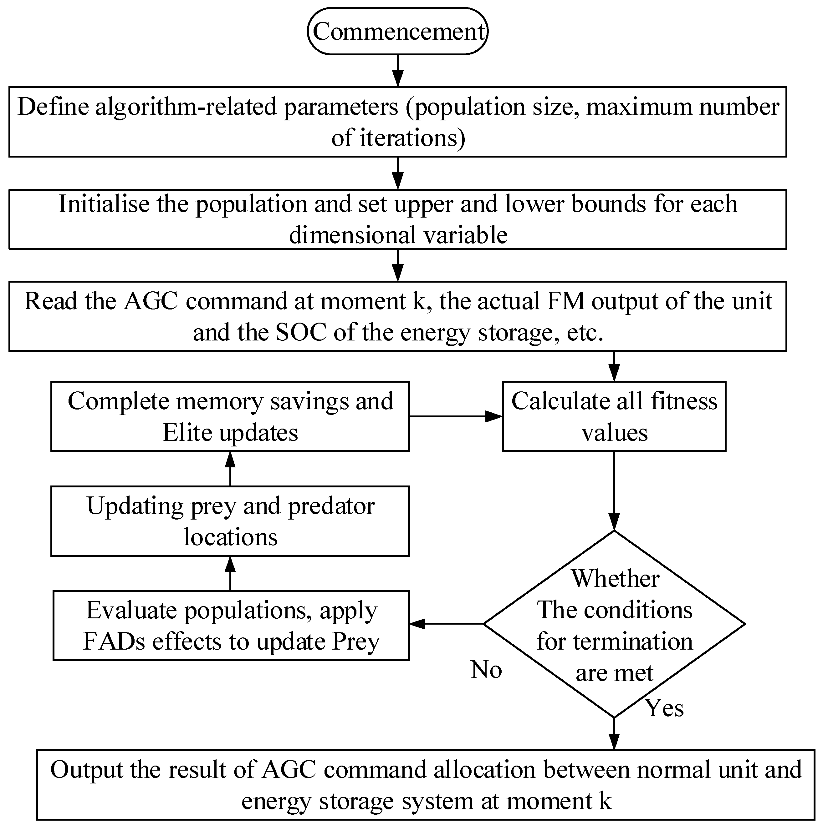
This equation will be used as a fitness function in the operation of the multi-objective marine predator algorithm to evaluate the degree of merit of the solution. The construction process of the adaptive ocean predation model includes:
Step1, initialise the control parameters, and randomly initialise the output power of each generating unit in the specified range;
Step2, establish the model of energy storage system participating in the optimal scheduling of the power system and set the constraints, and the constructed multi-objective function will be used as the fitness function to evaluate the advantages and disadvantages of the chaotic ocean predator;
Step3, evaluate the fitness values of all chaotic marine predators, determine the non-dominated solutions, and update the marine memory base based on the obtained non-dominated solutions;
Step4, evaluate the populations, apply the FADs effect and update the Prey matrix;
Step5, update the position of prey and predator in the chaotic marine predator;
Step6, update the Elite matrix;
Step7, using the hill climbing algorithm, try to improve the best answer and position obtained by the algorithm so far;
Step8, determine whether the maximum number of iterations or accuracy requirements are met, if satisfied, output the optimal non-dominated solution, if not, return to Step3.
The array of matrices of Elite supervises the search and finding of Prey based on their positional information, and another matrix of the same dimensions as Elite is called Prey, based on which the predator updates its position. Fish aggregating devices (FADs), or eddy formation in nature. Sharks, for example, are one of the largest marine predators, and spend 80% of their time in the vicinity of these FADs, and the rest of the time looking in different directions and dimensions for environments with different prey. Considered as local optima in MPA, they prevent the algorithm from falling into local optima during optimization.
The flowchart is as follows:
Figure 4.
Flowchart of the Adaptive Marine Predator Climbing algorithm.
In this paper, we propose to improve the performance of the proposed technique by using a hill-climbing (HC) local search algorithm to speed up the convergence rate and avoid falling into the local optimum point in order to solve the truss optimisation problem. When the proposed algorithm fails to improve the value of the cost function during the optimisation process and during several consecutive iterations (e.g., during a quarter of the iterations of the algorithm), the HC algorithm is used and attempts are started to improve the best answer and position obtained by the algorithm so far. The steps are as follows:
Calculate the improvement rate based on ImIter as:
If,then the hill climbing algorithm (HC) is run, and if , then the population is updated based on the optimal solution until ImIter is larger than a set criterion value.
The proposed hybrid approach is able to maintain a considerable balance between searchability and convergence speed in the multimodal search space. In addition, using the hill-climbing algorithm as a robust local search improves the marine predator algorithm and speeds up convergence in the unimodal search space.
4. Simulation results
The proposed method is simulated and verified in Matlab R2018b/Simulink environment. The technical specifications of the computer are processor Core i5-13500H@2.6GHz, RAM 16Gb.The two-region interconnected system model is used, and the parameters are set as follows: simulation time T=1000s; other parameters are taken, as shown in Table 1. In the table: M is the engine moment of inertia; D is the load damping coefficient; Tr is the re-heat time constant; TG is the governor time constant; Kr is the reheat coefficient; Tt is the air capacitance time constant; B is the frequency deviation factor, and p.u. is the standardized value (the same as the following); R is the unit tuning coefficient; and KS12 is the interaction gain of the contact line area. According to the maximum power point tracking strategy of wind power, CP() is very close to 0.45. Considering the predicted wind speed V(t), the radius of the wind turbine blade is taken as 65m, and the air density ρ is taken as 1.293kg·m-3. The wind farm employs 80 single 5MW units, and the total output of the wind turbines is 400MW, the total output of the thermal turbines is 2600MW, and the total output of the power system is 3000MW. In the simulation, the generator rate of change constraint (GRC) and governor dead band (GDB) are considered, and the typical value of GRC for thermal power units is taken as 0.0017MW·s-1. The variable range of the energy storage SOC is controlled from 10% to 90%, the capacity power of the storage power source is ±30MW/15(MW·h), and the optimal state of charge of the energy storage is 50%.
case 1: As shown in Figure 5a and 5b,when the wind speed changes from low to high, the simulation time is set to t=300s for a given load change, and a step perturbation is applied to the AGC system at t=200s to apply a step perturbation ΔPL1=0.08 and ΔPL2=0.06 to region 1 and region 2, respectively, requiring the wind speed to change, and the wind speed is changed from 6m/s to 9m/s at t=100s , with the corresponding AGC unified inertia The time constants are H1=4.8 and H2=5.6 , respectively.
From Figure 5c and 5d, it can be seen that in the process of wind speed changing from low to high, the parameter H increases, which makes the influence of wind speed fluctuation on the system frequency increase, which is manifested in the increase of the frequency deviation change amplitude and the increase of overshooting amount. After adding the optimised control strategy, this phenomenon can be effectively suppressed, so that the influence of frequency deviation change is obviously reduced. At the same time, for the frequency change caused by the load change t=200s, the proposed control strategy can also effectively reduce the fluctuation amplitude of the frequency deviation curve and overshooting amount.
case 2: As shown in Figure 6a and 6b, when the wind speed changes from high to low, the simulation time is set to t=300s for a given load change, and a step perturbation is applied to the AGC system at t=200s to apply a step perturbation ΔPL1=0.08 and ΔPL2=0.06 to region 1 and region 2, respectively, and the wind speed is required to change, and the wind speed is changed from 9m/s to 6m/s at t=100s , and the corresponding inertia of the AGC system is H1=5.6 and H2=4.8.
As can be seen in Figure 6c and 6d, the parameter H decreases as the wind speed varies from high to low. According to the physical effect of H on the mechanical characteristics of the system, compared with the control effect at high wind speeds, although the reduction of H itself will make the turbine output power less affected by frequency fluctuations, the inclusion of the control strategy makes the controller regulation compensate for the changes in the model parameters due to the effect of series connection between the system model and the controller.
Case 3: When random wind speed, random load, set the simulation time t=1000s , impose random wind speed changes to the system, the two regions of the wind speed changes as shown in Figure 7a, region 1 and region 2 load perturbation as shown in Figure 7c, Figure7d .
As shown in Figure 7e and 7f, the maximum frequency deviation of this paper's method is smaller than that of the comparison method that includes the particle swarm algorithm (PSO), which cannot respond to the assigned AGC commands in a timely manner, resulting in a significantly larger frequency deviation.
As shown in Figure 8 comparing the continuous frequency fluctuation of the traditional energy storage system after adopting the FM strategy, due to the fact that the energy storage system starts charging and discharging regulation once it exceeds the dead zone of the action, and the frequent exchanges do not have a self-recovery process, which results in the gradual decrease of the SOC to near the lowest limit, and based on the SOC trend, if the frequency continues to decrease for a period of time, the energy storage system may intermittently withdraw from the FM action. This will not only seriously affect the frequency regulation effect, but also reduce the utilisation efficiency of the energy storage system. In this paper, since the method takes most of the frequency regulation responsibility at the beginning of the step load disturbance occurrence, and the traditional unit handles the comparison of the climbing rate is smaller than that of the traditional ARR control method, the energy storage output exits more slowly, so the energy storage SOC decreases the most before 100 seconds, and after that, it enters into the state of fine-tuning of the energy storage SOC, the constant power charging, the This paper's method guarantees the effect of the frequency regulation, while both reducing the frequency of the The method in this paper ensures the effect of FM, while reducing the frequent actions of the energy storage system, but also maintains the charging state of the bat-type energy storage system at certain intervals to meet the FM commands of the subsequent system, which confirms the effectiveness of the strategy. The Area Control Error algorithm (ACE) and the Particle Swarm Optimization (PSO) algorithm for frequency control have been chosen for the comparison in this paper. Furthermore, this paper compares the results of the literature in similar contexts. The reference [23] provides the optimal control strategy of a Multi-Objective Grid Adaptive Search (MOMADS) algorithm, which reduces the frequency deviation of the two regions by an average of about 0.0015 Hz. An Aspen Whisker Search (IBAS) algorithm has been proposed in reference [24], which reduces the frequency deviation by an average of about 0.0032 Hz. The Adaptive Marine Predator Climbing algorithm proposed in this paper reduces the frequency deviation by an average of 0.0044 Hz, which provides better frequency control than the results of algorithms in the literature.
5. Conclusions
In this paper, for the complexity of AGC in wind power high penetration, based on the FM characteristics of common unit and energy storage system, comprehensively considering the processing characteristics of unit and energy storage FM, the operating characteristics of energy storage system, and the influence of different types of load disturbance on the way of assigning AGC FM duties, we propose the FM control strategy of wind power high penetration system considering energy storage SOC:
1) Establish a multi-area AGC FM control optimisation model for wind power penetration, and analyse the effects of wind speed variations on system parameters. A real-time optimisation algorithm of adaptive marine predator algorithm improved using hill climbing (HC) algorithm is proposed.
2) An energy storage SOC management scheme, i.e., a self-recovery action control strategy for the energy storage system, is formulated. When the energy storage enters deep charging and deep discharging, the SOC is preferentially coarsely tuned to limit the SOC to the normal range of 40% to 60%; when the energy storage is idle or assumes a smaller FM responsibility, the SOC is restored to the reference range of 49.9% to 50.1% by fine tuning.
3) A dynamic model of the dual-area grid FM is constructed using the Matlab/Simulink platform, and the total objective function for optimisation is proposed and simulation and comparison experiments are carried out. The results for three different cases of power load uncertainty and renewable energy impact are discussed. The results show that the control method proposed in this paper outperforms other methods in terms of integrated regulation performance and FM compensation gain under step and continuous load disturbance conditions. The energy storage SOC fluctuation is small and can self-recover to the baseline range, which ensures the continuous and efficient operation of the energy storage system. It also effectively extends the life cycle of the battery energy storage system, reduces the operation and maintenance cost of the energy storage system, and improves the operational reliability. This paper lacks consideration of extreme weather and larger scale classical grid modelling scenarios, as well as deeper consideration of the battery health state of Li-ion batteries and the depth of battery Pack discharge, and will focus on this deficiency in future research.
Author Contributions
Conceptualization, methodology and original manuscript prepared by Yingjie Hu and Chenggen Wang; reviewed and edited by Yingjie Hu, Chenggen Wang and Xiaoming Zou. All authors have read and agreed to the published version of the manuscript.
Funding
This research was funded by [the Science &Technology Program of State Grid Jiangsu Electric Power Co., Ltd.] grant number [J2023128] and The APC was funded by [State Grid Jiangsu Electric Power Co., Ltd.].
Institutional Review Board Statement
Not applicable.
Informed Consent Statement
Not applicable.
Data Availability Statement
Not applicable.
Conflicts of Interest
The authors declare no conflict of interest.
Nomenclature
| Δf | frequency deviation | Tw | turbine filter time constant |
| ΔP | deviation of the active power of the system | optimal rotational speed at the current wind speed | |
| D | damping coefficient of the system | Pt | output power of the wind generator |
| M | equivalent rotational inertia of the system | EB | rated capacity of the energy storage system |
| SOC | actual state of charge of the energy storage | He | turbine equivalent inertia time constant |
| PW | active power of wind units | Ta | turbine time constant |
| PES | active power of energy storage systems | PES | actual response power of the energy storage |
| PL | active power of load side | TG | governor time constant |
| rotational speed of the wind turbine at the current moment | PG | active power of thermal power units | |
| CP | performance coefficient of the wind turbine | SOC0 | initial state of charge of the energy storage |
| ratio of the rotor blade tip speed to the wind speed | TES | charge/discharge time constant of the energy storage system | |
| V(t) | real-time wind speed | PGN | rated output power of the genset |
| pitch angle of the paddle | PN | rated capacity of the wind turbine | |
| air density | wind power penetration rate | ||
| low-speed shaft rotational speed | f0 | initial frequency of the system | |
| r | radius of the wind turbine blades | f | rated frequency |
| ΔX2 | incremental frequency change of the wind turbine after the filter | J | rotational inertia of the wind turbine |
| falling rate coefficient | R | the generator modulation factor | |
|
KWP /KWI |
inherent PI controller parameters of the wind turbine | Hh | inherent inertia time constant of the thermal power unit |
| optimal rotational speed at the current wind speed | Pchm | the maximum charging power of the energy storage system | |
| Pcr max | the maximum power of the storage system during charging recovery | ΔX1 | incremental change in frequency of the turbine after the sensor |
| Vtotal | total investment cost of the BESS | ntotal | cycle life of the BESS |
| uch.t | BESS switches from discharging to charging state during t | udis.t | BESS switches from charging to discharging state during t |
References
- TANG Jian, SU Jiantao, YAO Yuge, et al. Technical analysis of power system frequency regulation by wind power for new power system[J].Thermal Power Generation,2022, 51(07: :1-8.
- LI Jianlin, NIU Meng, WANG Shangxing, et al.Operation and control analysis of 100 MW class battery energy storage station on grid side in Jiangsu power grid of China[J].Automation of Electric Power Systems, 2020, 44(2) :28-35.
- MEJÍA-GIRALDO D, VELÁSQUEZ-GOMEZ G, MUÑOZ GALEANO N, et al.A BESS sizing strategy for primary frequency regulation support of solar photovoltaic plants[J].Energies,2019, 12:317.
- WANG Ruifeng, GAO Lei, SHEN Jie, et al. Frequency regulation strategy with participation of variable-speed wind turbines for power system with high wind power penetration[J].Automation of Electric Power Systems, 2019,43(15) :101-108.
- XU Guoyi, HU Jiaxin, GUO Shufeng, et al. Improved frequency control strategy for over-speed wind turbines[J]. Automation of Electric Power Systems, 2018, 42(8) :39-44.
- LI Yingying, WANG Delin, FAN Linyuan, et al. Variable Coefficient Control Strategy for Frequency Stability of DFIG Under Power-limited Operation[J]. Power System Technology, 2019, 43(8) :2910-2917. LIU Hongbo,PENG Xiaoyu, ZHANG Chong, et al. Overview of wind power participating in frequency regulation control strategy for power system[J].Electric Power Automation Equipment, 2021, 41(11) :81-92.
- Zhang Yuze. Correction of AGC Parameters with Large-scale Wind Power Integration Systems [J]. Electrical automation,2019,41(1):28-31.
- Li Shichun, Tang Hongyan, Liu Daobing, et al. Calculation of equivalent inertia time constant of power system with virtual inertial response of wind power [J]. Renewable Energy Resources,2018,36(10):1486-1491.
- TIAN Xinshou, WANG Weisheng, CHI Yongning et al. Variable Parameter Virtual Inertia Control Based on Effective Energy Storage of DFIG-based Wind Turbines [J]. Automation of Electric Power Systems,2015,39(5):20-26,33.
- GLOE, ARNE, JAUCH, CLEMENS, CRACIUN, BOGDAN, et al. Continuous provision of synthetic inertia with wind turbines: implications for the wind turbine and for the grid[J]. IET renewable power generation,2019,13(5):668-675.
- DING Dong, LIU Zongqi, YANG Shuili, et al. Battery energy storage aid automatic generation control for load frequency control based on fuzzy control [J]. Power System Protection and Control,2015,43(8):81-87.
- LI Xinran, DENG Tao, HUANG Jiyuan, et al. Battery Energy Storage Systems Self-adaptation Control Strategy in Fast Frequency Regulation [J]. High Voltage Engineering,2017,43(7):2362-2369.
- Li Xinran, Huang Jiyuan, Chen Yuanyang, et al. Battery Energy Storage Control Strategy in Secondary Frequency Regulation Considering Its Action Moment and Depth [J]. TRANSACTIONS OF CHINA ELECTROTECHNICAL SOCIETY,2017,32(12):224-233.
- A. Faramarzi, M. Heidarinejad, B. Stephens, and S. Mirjalili, ‘‘Equilibrium optimizer: A novel optimization algorithm,’’ Knowl.-Based Syst., vol. 191,Mar. 2020, Art. no. 105190.
- HU Zechun, XIA Rui, WU Linlin, et al. Joint Operation Optimization of Wind-Storage Union With Energy Storage Participating Frequency Regulation [J]. Power System Technology,2016,40(8):2251-2257.
- YANG Xiaoping, SONG Zhixiang, HU Yang, et al. Three-phase Power Flow Calculation for Medium-low Voltage Distribution Network Considering Control Equations of Distributed Generations [J]. Proceedings of the CSU-EPSA,2019,31(3):16-22.
- GUHA, DIPAYAN, ROY, PROVAS KUMAR, BANERJEE, SUBRATA. Load frequency control of interconnected power system using grey wolf optimization[J]. Swarm and Evolutionary Computation,2016,2797-115.
- Xilin Z, Zhenyu L, Bo F, Li H, Chaoshun L, et al. Research on the Predictive Optimal PID Plus Second Order Derivative Method for AGC of Power System with High Penetration of Photovoltaic and Wind Power[J]. Journal of Electrical Engineering & Technology, 2019, 14(3): 1075.0-1086.0.
- Yan Z, Guoqiang Y, Kaiming L, Hongxing W, Menglei G, Jianyong Z, et al. Improved Particle Swarm Optimization-based Thermal Power-energy Storage Combined AGC Frequency Regulation Control[J]. 2020 IEEE 3rd International Conference of Safe Production and Informatization (IICSPI), 2020.
- LI Ruo, LIXinran, TAN Zhuangxi, et al. Integrated Control Strategy Considering Energy Storage Battery Participating in Secondary Frequency Regulation [J]. Automation of Electric Power Systems,2018,42(8):74-82.
- HUANG Yawei, LI Xinran, HUANG Jiyuan, et al. Analysis of Control Methods for AGC with Battery Energy Storage System [J]. Proceedings of the CSU-EPSA,2017,29(3):83-89.
- Gaojun M, Qingqing C, Yukun S, Yufei R, Feng Z, Yao W, Ling S, et al. Energy Storage Auxiliary Frequency Modulation Control Strategy Considering Ace And Soc Of Energy Storage[J]. IEEE Access, 2021, 9: 26271-26277.
- LU Xiaojun, YI Jianwei, LI Yan Optimal Control Strategy of AGC With Participation of Energy Storage System Based on Multi-objective Mesh Adaptive Direct Search Algorithm [J]. Power System Technology,2019,43(6):2116-2124.
- JIN Lixin, ZHU Wu, HUA Yun-hao, et al. Optimal Control Strategy of Battery Energy Storage System Participating in AGC Based on Improved Beetle Antennae Search Algorithm [J]. Water Resources and Power,2021,39(7):206-210.
- Liang J J, Qin A K, Suganthan P N, et al. Comprehensive learning particle swarm optimizer for global optimization of multimodal functions[J]. IEEE transactions on evolutionary computation, 2006, 10(3): 281-295.
Figure 1.
Analysis of system frequency characteristics.
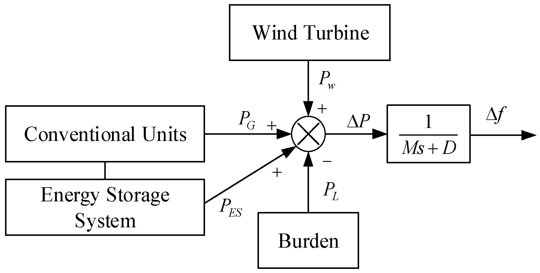
Figure 2.
Single-area AGC model with wind turbine generators.
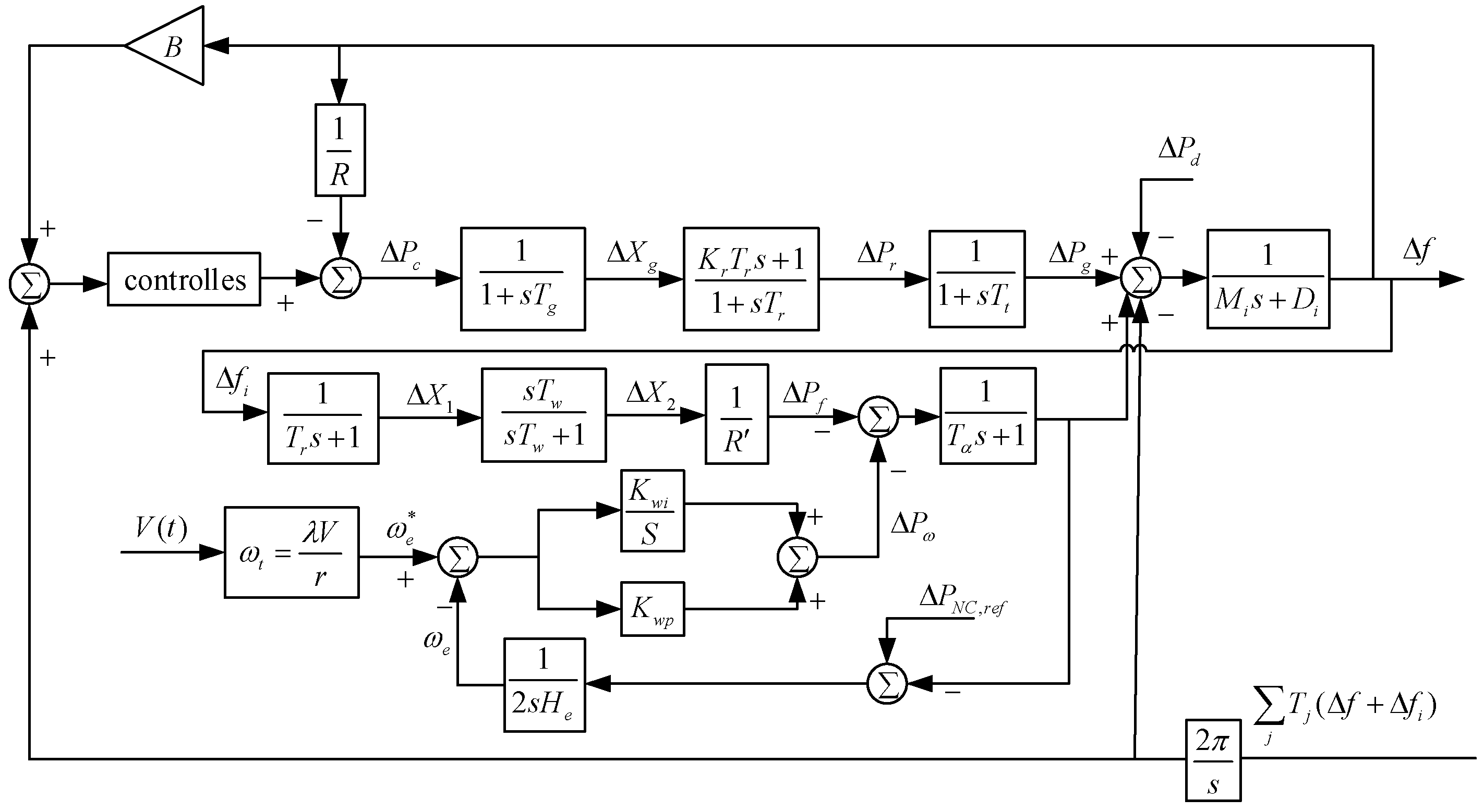
Figure 3.
Equivalent model of energy storage system.
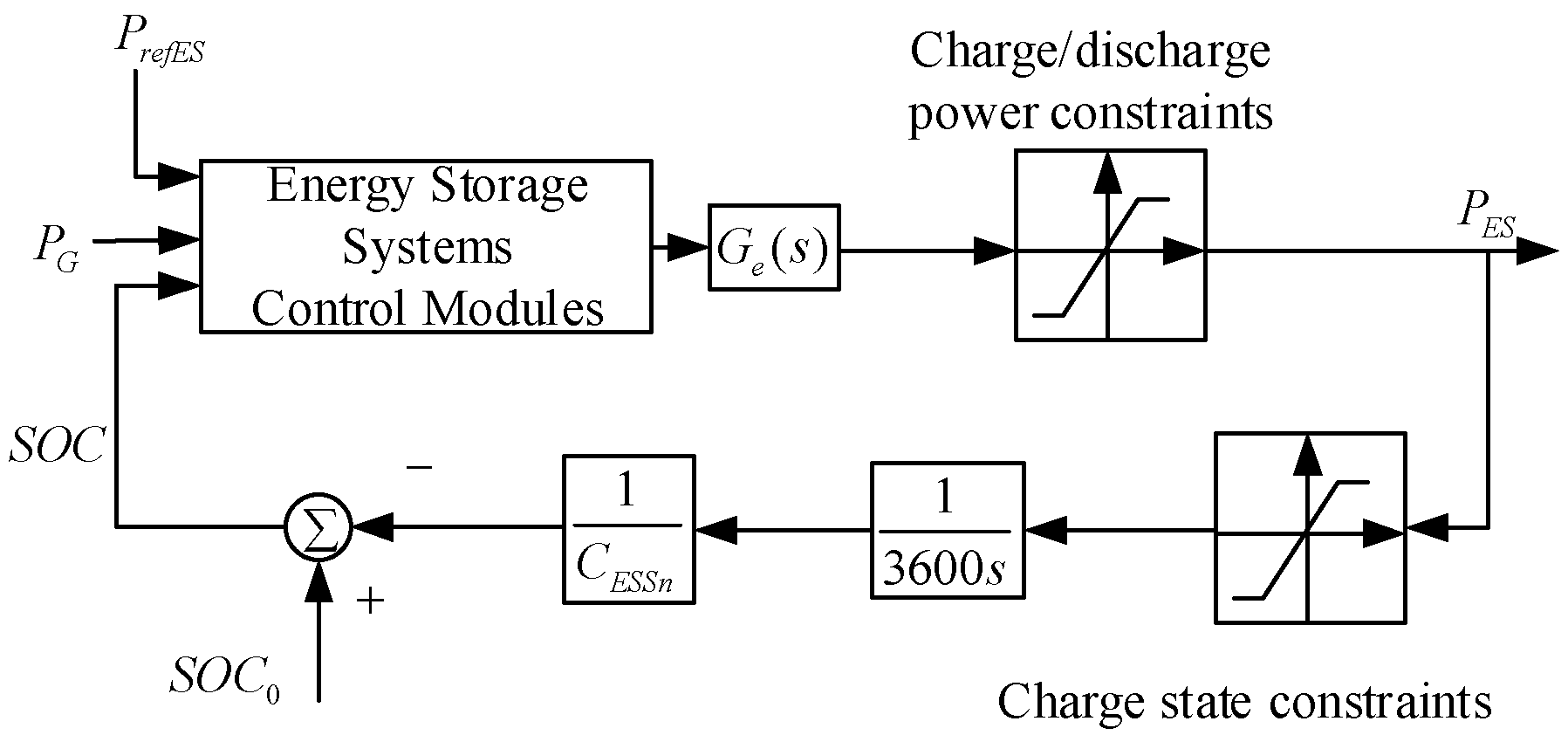
Figure 5.
(a) Wind speed input for case 1, (b) Fan output for case 1, (c) Change in frequency deviation in region, (d) Change in frequency deviation in region 2.
Figure 5.
(a) Wind speed input for case 1, (b) Fan output for case 1, (c) Change in frequency deviation in region, (d) Change in frequency deviation in region 2.
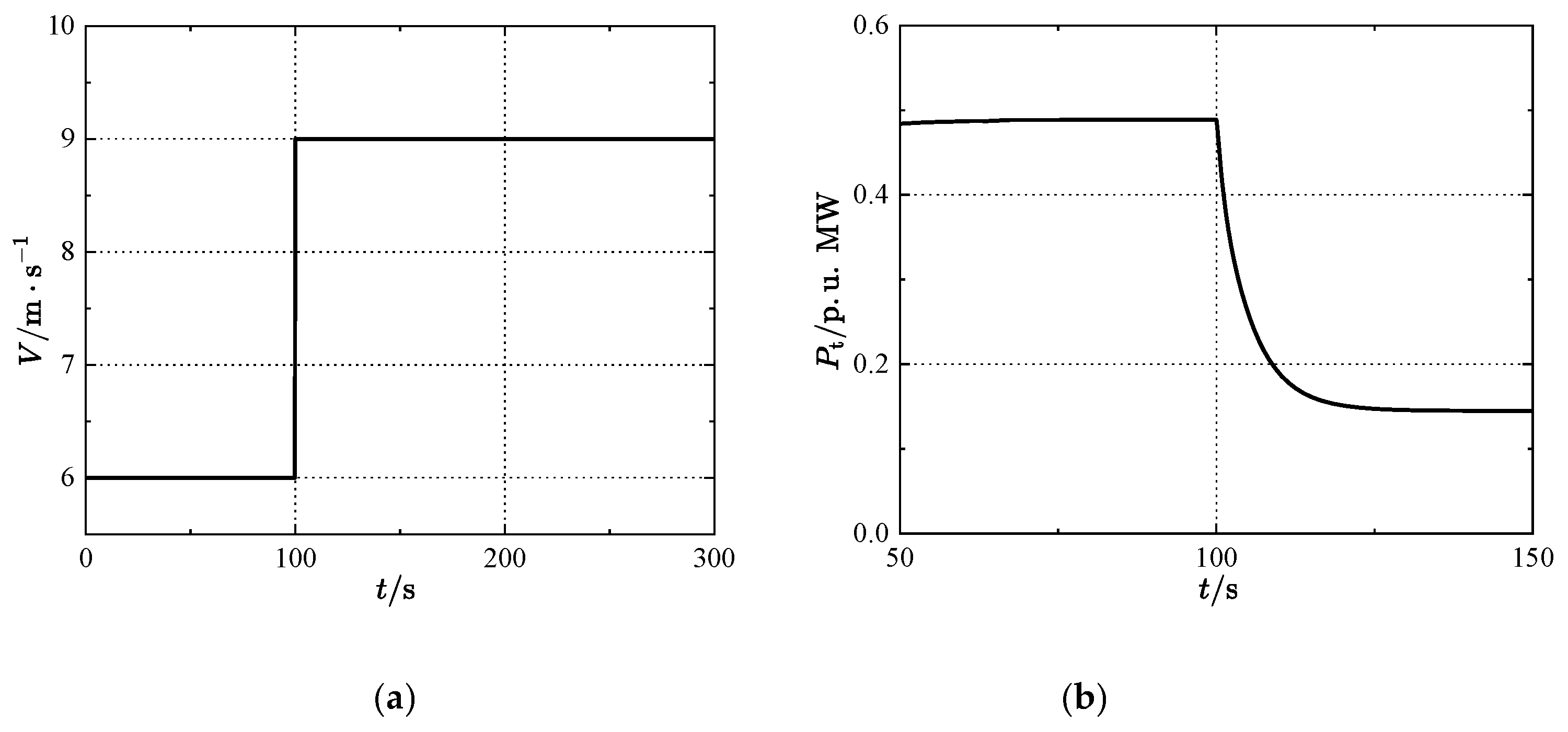
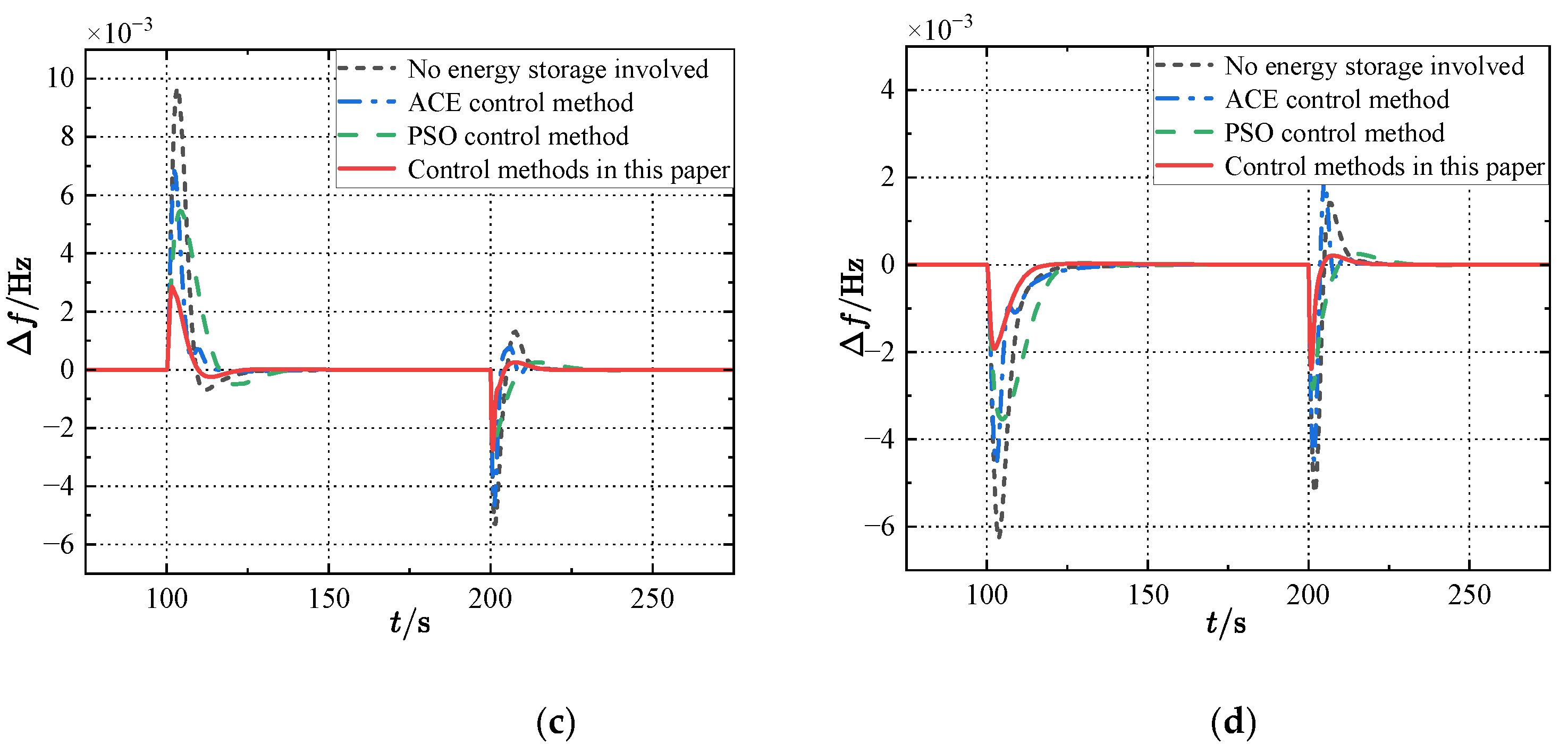
Figure 6.
(a) Wind speed input for case 2, (b) Fan output for case2, (c) Change in frequency deviation in region 1, (d) Change in frequency deviation in region 2.
Figure 6.
(a) Wind speed input for case 2, (b) Fan output for case2, (c) Change in frequency deviation in region 1, (d) Change in frequency deviation in region 2.
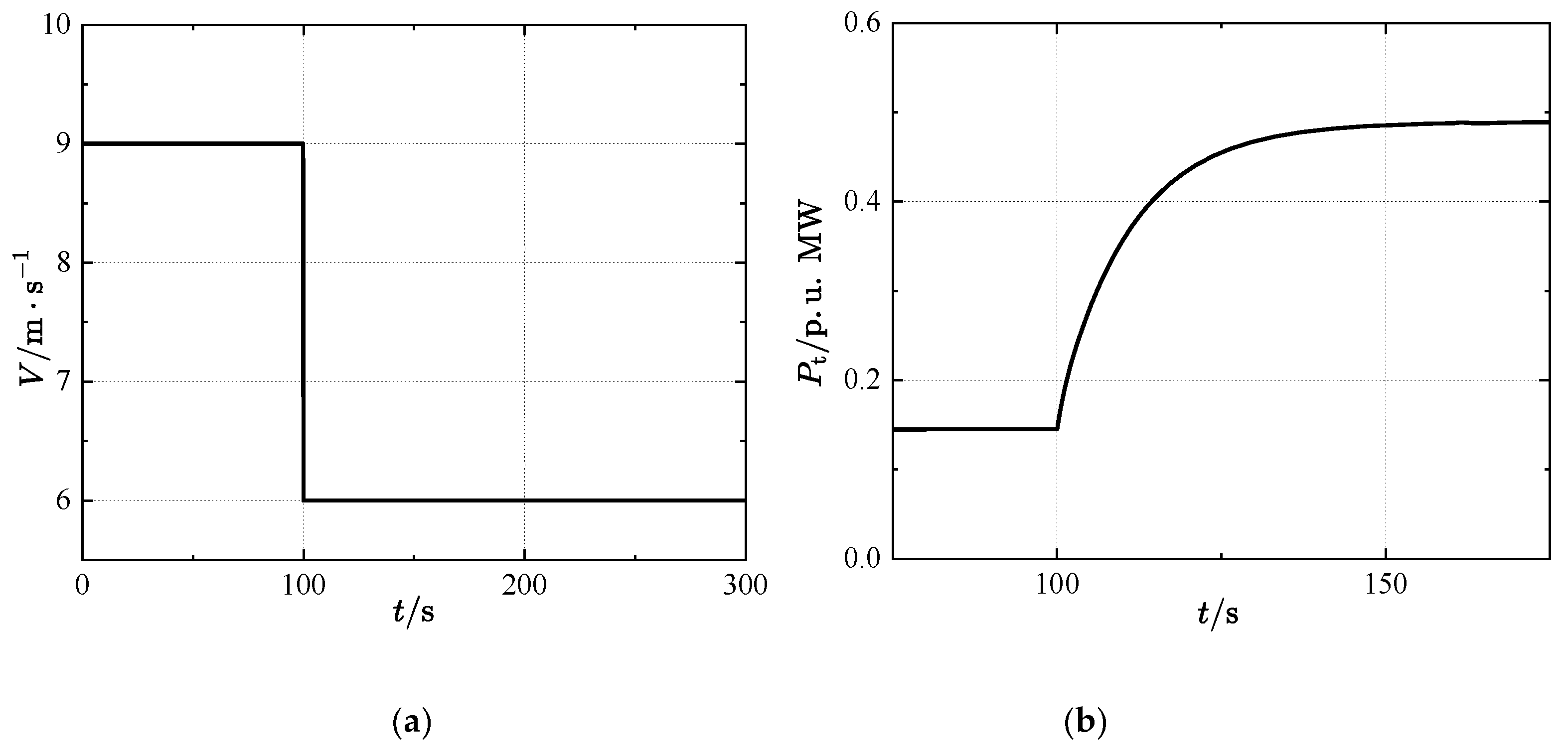
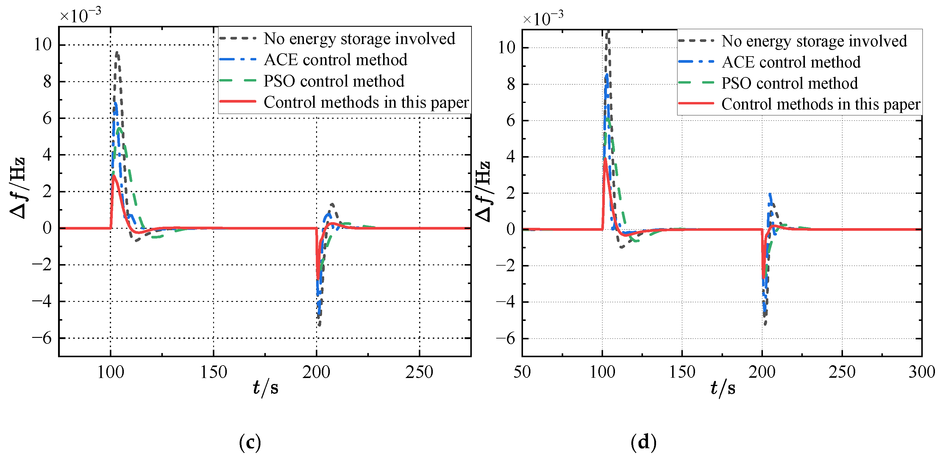
Figure 7.
(a) Stochastic wind speed variation, (b) Fan output for case 3, (c) Randomized load changes in Region 1, (d) Randomized load changes in Region 2, (e) Change in frequency deviation in region 1, (f) Change in frequency deviation in region 2.
Figure 7.
(a) Stochastic wind speed variation, (b) Fan output for case 3, (c) Randomized load changes in Region 1, (d) Randomized load changes in Region 2, (e) Change in frequency deviation in region 1, (f) Change in frequency deviation in region 2.
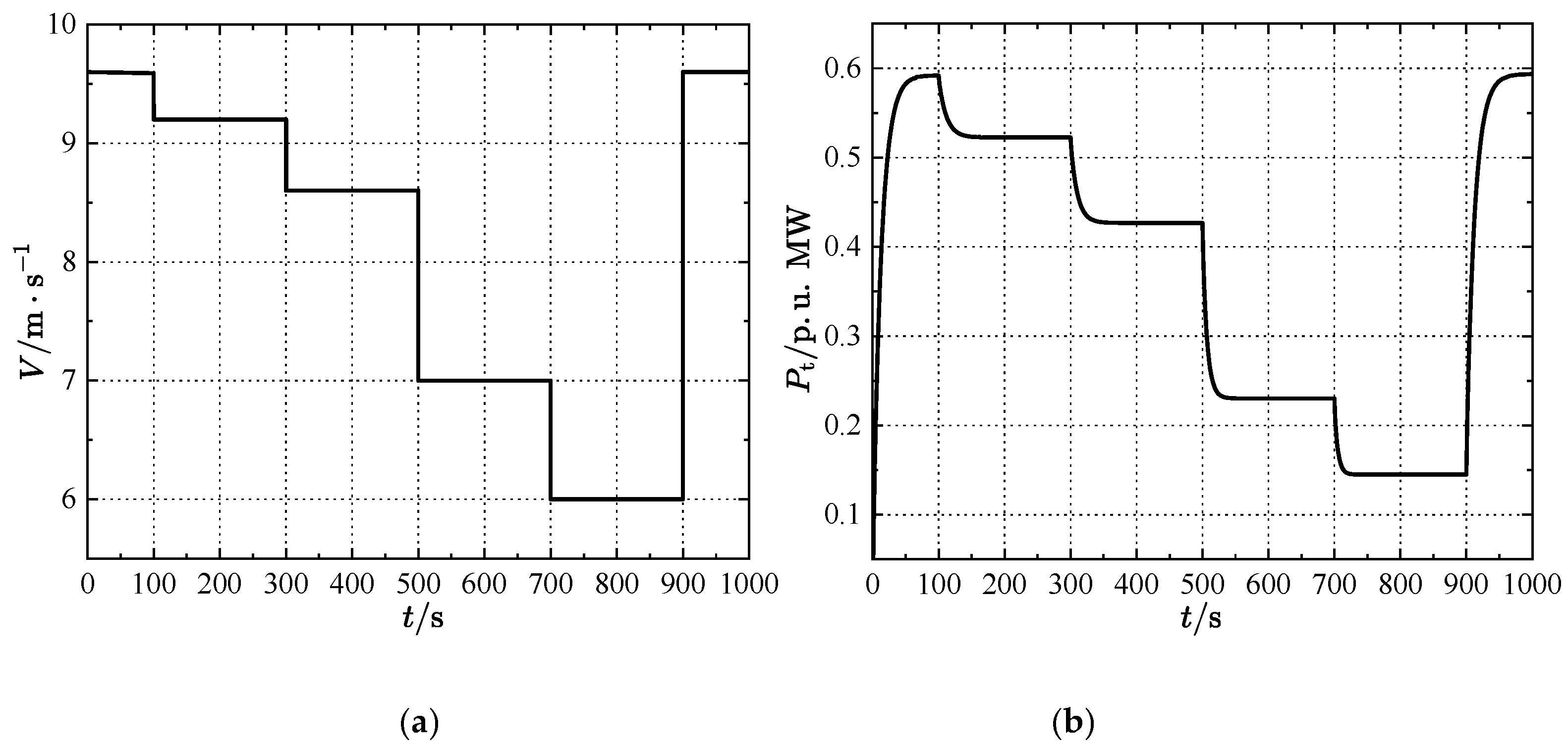
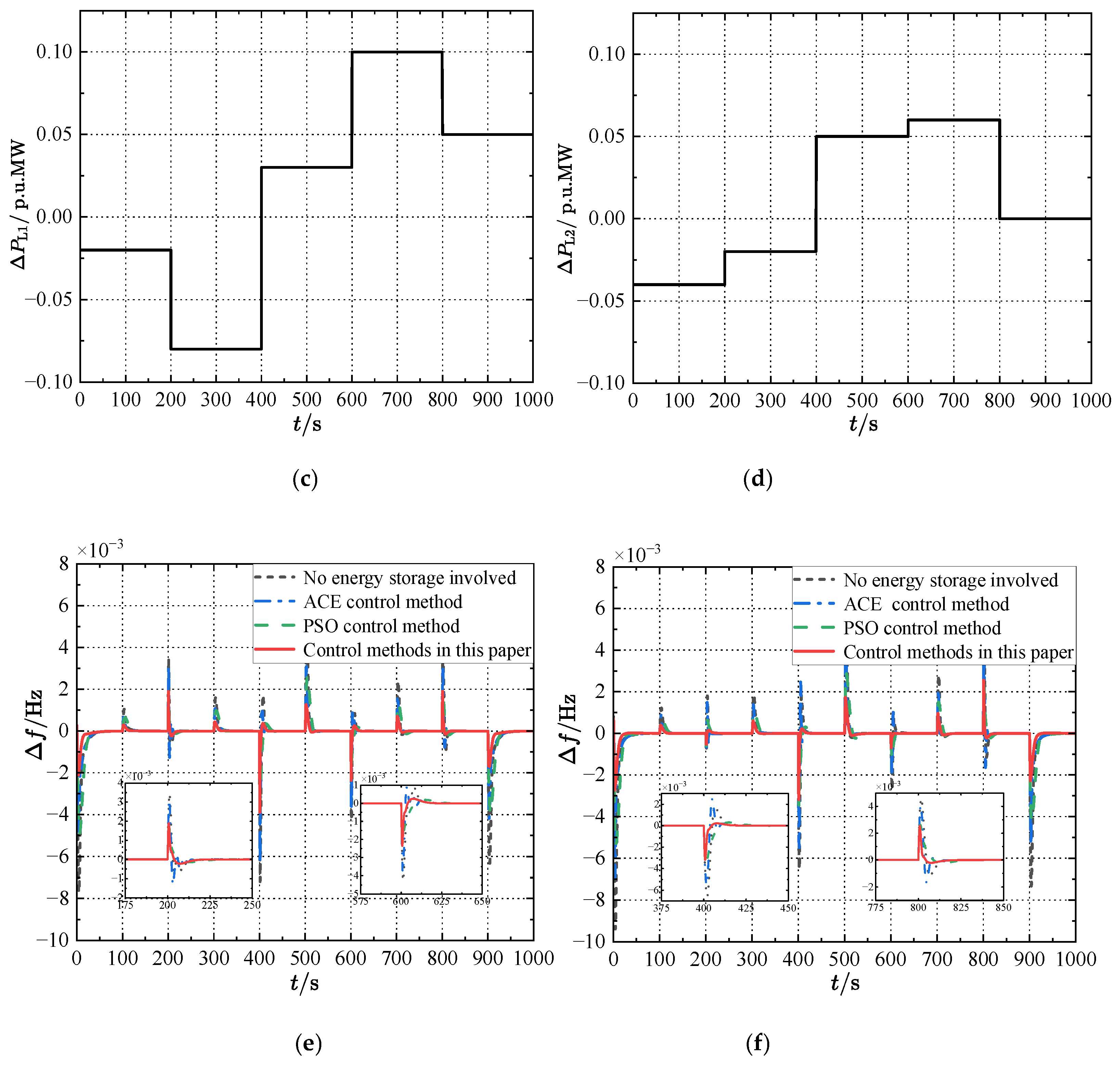
Figure 8.
SOC variation curve of storage battery.
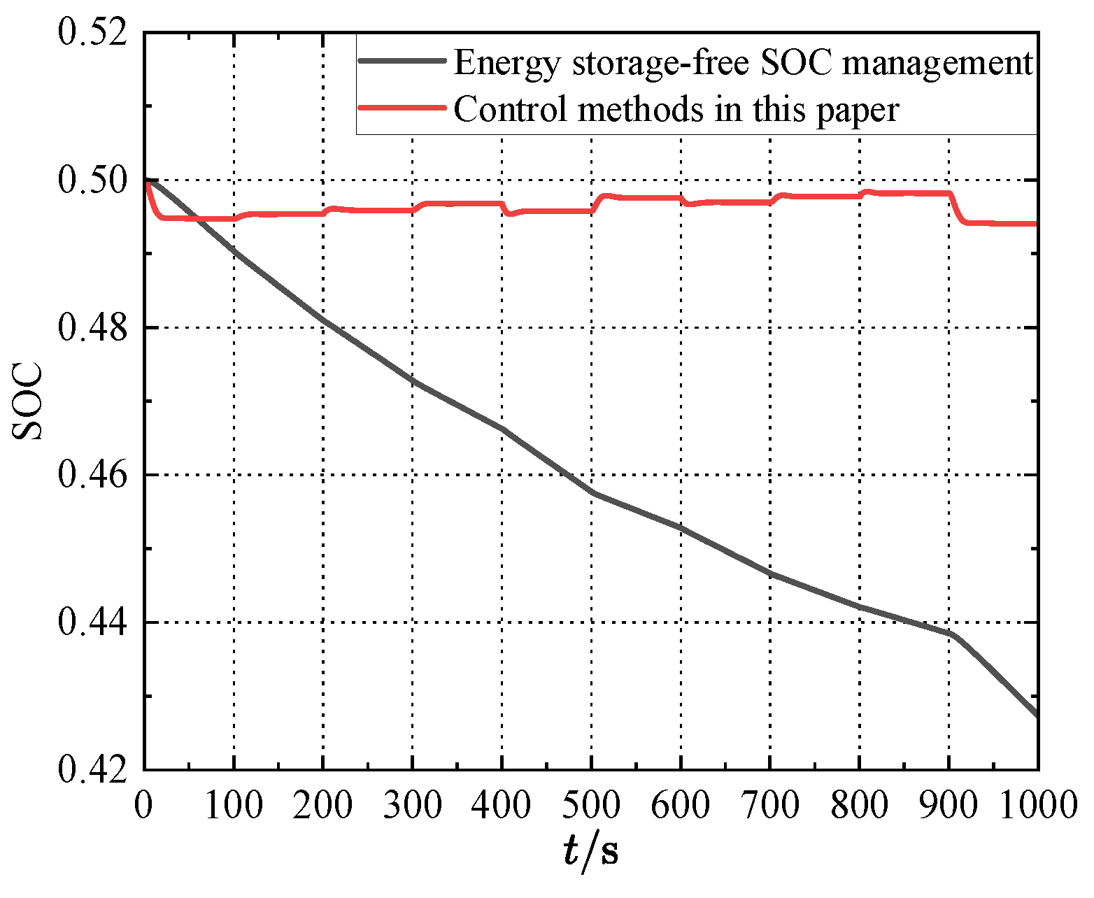

Table 1.
Parameters of the two-region AGC system.
| Parameters | Region 1 | Region 2 |
|---|---|---|
| Mi | 10.5 | 10 |
| Di | 2.75 | 2.5 |
| Bi | 35 | 30 |
| Ri | 0.036 | 0.03 |
| Tri | 10 | 8 |
| Tgi | 0.1 | 0.08 |
| Kri | 0.25 | 0.2 |
| Tti | 0.2 | 0.15 |
| Tij | 0.0868 | 0.0867 |
Disclaimer/Publisher’s Note: The statements, opinions and data contained in all publications are solely those of the individual author(s) and contributor(s) and not of MDPI and/or the editor(s). MDPI and/or the editor(s) disclaim responsibility for any injury to people or property resulting from any ideas, methods, instructions or products referred to in the content. |
© 2024 by the authors. Licensee MDPI, Basel, Switzerland. This article is an open access article distributed under the terms and conditions of the Creative Commons Attribution (CC BY) license (http://creativecommons.org/licenses/by/4.0/).
Copyright: This open access article is published under a Creative Commons CC BY 4.0 license, which permit the free download, distribution, and reuse, provided that the author and preprint are cited in any reuse.


