Submitted:
14 December 2024
Posted:
17 December 2024
You are already at the latest version
Abstract
Multiple serial interfaces have emerged to match system requirements between
devices,
from slower speed buses such as I²C to high throughput serial interfaces like JESD204.
To fill the gap of a medium speed protocol and to resolve I²C shortcomings,
the MIPI Alliance developed the I3C specification, a royalty-free next
generation version of I²C with new features and backward compatibility.
Since MIPI Alliance I3C's work includes only the specification,
it depends on third-party vendors to develop their own cores according the specification.
There are only a few processing system that contain I3C controllers, each
with their own partial implementation of the specification, and there are no
open-source controller cores.
Thus, this work presents an open-source I3C controller HDL framework
that operates at the maximum specified SDR frequency and is compatible
with the Linux kernel.
Both the core and Linux kernel driver are under permissive open-source licenses.
The solution aims mostly development boards with Xilinx Zynq and Intel Cyclone
SoC, nevertheless the structure of the project allows to be ported
to other vendors and carriers
Keywords:
I3C
; FPGA
; HDL
; IP
; GNU/Linux
1. Introduction
The communication between a peripheral and a controller in an electronic circuit depends on the system requirements, such as transmission rate, ratio between transfer and idle times, and distance between the devices on the bus. In simpler circuits, the controllers are concentrated in a single processing system, however, more complex system might have more than one processing system and even more than one controller per bus.
The Inter-Integrated Circuit (I2C) interface is sufficient for applications with slower transmission rates requirements and recurring idle times. Since it uses only two traces to communicate with multiple devices, its Printed Circuit Board footprint is considerably smaller when compared with others protocols such as Serial-Peripheral Interface (SPI). However, its shortcomings have become increasingly problematic with the performance expectation of new electronic projects and the release of I2C compatible parts.
With an ever-increasing catalog of parts available by multiple vendors, the fixed identifiers are not unique and often suffer from address collision. Also, if a part has no option to modify part of the identifier, for example, by pulling-up a peripheral’s pin to bit flip a bit of the address, one cannot connect the same part twice to the same I2C bus.
The I2C maximum rate of 3.4Mpbs on its high speed mode [1] disallows its use in modern applications that require higher data rates. This rate is bounded by the step response of the open drain electronic gate on the bus, thus higher frequencies would result in transient and undefined logic state when the signal gets sampled at the clock edge.
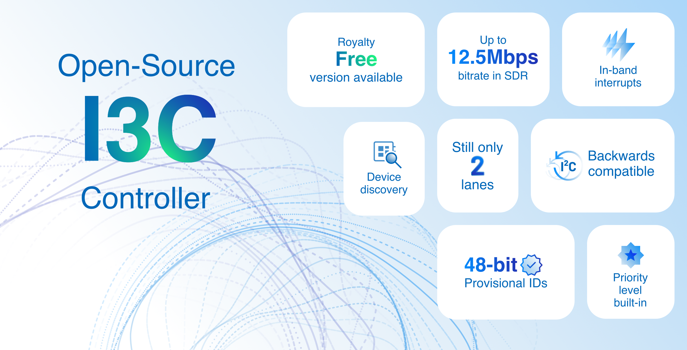
With the intent of overcoming the limitations of the I2C interface, the Mobile Industry Processor Interface (MIPI) Alliance specified the Improved Inter-Integrated Circuit (I3C) interface. This interface defines long and unique identifiers per part, and allows transmission rates up to 12.5Mbps in Single Data Rate (SDR) mode on grounds of the dynamic push-pull configuration..
Since the MIPI Alliance only defines the interface’s specification, it is up to vendors to implement their own Intellecutal-Property (IP)s. Currently, Silvaco, Cadence, and Synopsys supply paid I3C controller and peripheral IPS that are implemented in a few parts and processing systems from NXP, ST, and Texas Instruments. A free I3C peripheral IP is provided by NXP, a reduced variant of the IP distributed by Silvaco [2]. However, there is no free I3C controller IP.
Therefore an engineer that aims to use I3C parts is limited to the few processing systems available with I3C controllers, which are not necessarily compatible with his project requirements. For example, the solutions from NXP [3], ST [4], and Texas Instruments[5] are supported for bare metal applications only, and it might be a project requisite to run an operating system on the processing system. This scenario also hinders the adoption and improvement of the protocol, as the paid controllers available are provided with restrictive terms and often under Non-Disclosure Agreements.
1.1. Related Work
Several researches have contributed to the understanding and validation on I3C, from design and implementation to verification and performance analysis.
Anusha et al. [6] focuses on the development of a verification environment following the Universal Verification Methodology guidelines and template, which aims to validate the correct implementation of I3C. Their developed scoreboard seems to lack validation of the timing requirements and violations of the protocol, instead, focuses on the monitored data transferred.
Shreyash et al. [7] also aims to development platform following the same guidelines, however provides more details on the test environment. The test environment is composed of one I3C Peripheral under test, and two agents: one I3C Controller and one I2C Peripheral, with the intend of mimicking a mixed-bus operation. It’s sequencer also seem to consider the timing of transactions, beyond the ordering presented by [6].
Gao et al. [8] aims to address the fixed approach of [6] and [7] by proposing a flexible hardware architecture. They introduced a configurable structure in the hardware design paired with a software layer to modify the hardware architecture and functionality. Their attention to include an error injection test to validate if the target can recover according the protocol requirements, is acknowledged and cherished.
All contributions in [6,7], and [8] could be useful for the development of new I3C Peripherals. [7] explicit clarification of the agents and design under test is critical, since the logic required to implement an I3C Controller and peripheral are largely distinct.
Mario et al. [9] created a test environment using hardware in loop approach to verify the legacy compatibility of the I3C Controller. Their regard to the timing verification is appreciated, since the I3C protocol exceptionally relies on timing to differentiate transfers and states, for example, the I3C transfers are hidden from I2C devices by setting the clock high period less than the I2C Spike Filter.
Yadhu et al. [10] proposes the design and implementation of an I3C Controller simulated and implemented using an AMD Xilinx Spartan 7 Field-programmable Gate Array (FPGA). The presented work stops at the simulation of the I3C Controller, however it is not clear of the correctness of the implemented protocol was verified and lacks testing on hardware. The source of the implemented controller could not be retrieved for analysis.
Despite these significant works, no original I3C Controller has been tested on hardware, nor has its source code distributed. The lack of an open-sourced I3C Controller framework limits accessibility for further development and practical adoption, an unfortunate pitfall when considering that the specification is royalty free.
2. Materials and Methods
2.1. Background
The I3C protocol is meant to substitute I2C as the industry standard for mid-speed serial communication. This section explores its electrical characteristics and features to provide a basis for the desired implementation.
2.1.1. Standard Data Rate
To enable higher speed than its predecessor, the I3C interface specifies a clever arrangement of open drain and push-pull modes that define the sdr.
The open drain mode, Figure 1, shares the same configuration as I2C. The logical high level (set bit) is achieved by a weak pull-up, and the logical low level (unset bit) by a short to ground. This configuration allows multiple peripherals to safely drive the Serial Data (SDA) lane, allowing them to acknowledge transfers at the Acknowledge-bit (ACK-bit) and send data on a single bidirectional lane. However, the weak pull-up has a high rise time, which limits the maximum frequency.
To increase the maximum operating frequency, the I3C interface allows the SDA line to be switched from open drain to push-pull mode. The push-pull mode uses a totem-pole driver, Figure 1b, and the handoff occurs in a timed pattern to ensure that no other device attempts to drive the SDA line while it is being driven in push-pull mode, as this would result in a short circuit.
The specified minimum high and low clock states is 24ns and together with the minimum setup/hold (/) times and rise/falling times (/), the maximum operating frequency is 12.5MHz.
The I3C specification disallows clock stretching, and only the active controller can drive the Serial Clock (SCL) line, which has the advantage that the SCL line can be driven only in push-pull mode, and eliminates the possibility of a hang bus due to malformed SCL state, issue common on I2C buses.
2.1.2. In-Band Interrupt
In-Band Interrupt (IBI) is a feature that allows peripherals to trigger interrupts to the I3C Controller. The priority level of the interrupt is encoded in the device address, with lower addresses having higher priority [11]. This is enabled by the arbitration process that occurs during the broadcast address phase of an I3C transfer.
The arbitration process works by each device tracking the bits during the broadcast address phase against their own addresses. At each address bit, the devices that want to send an interrupt send their addresses and, if the current bit is unset and the device’s own address bit is set, then the device has lost the arbitration to another device with a higher priority. The process continues until the broadcast address phase is complete and the controller shall acknowledge the interrupt request and receive the Mandatory Data Byte (MDB).
The arbitration process occurs in two scenarios:
- 1.
- The controller initiates a transfer with a Start, followed by the I3C Broadcast Address or a target device address; the interrupt sender drives the SDA with its own address.
- 2.
- The bus is in bus available condition and the interrupt issuer pulls the SDA line low, the controller notices, pulls the SCL line low (completing a Start), and provides clocks cycles for the peripheral to send its address.
Figure 2 illustrates an arbitration process in which three devices attempt to issue an IBI during the broadcast address phase. The controller initiated a transfer with a Start condition.
Note that the arbitration process can only occur after a Start, a peripheral cannot request an interrupt during a transfer, even after a Repeated Start.
The MDB contains values specified by MIPI, which are kept up to date at the I3C MDB Values Implementers table [12].
2.1.3. Dynamic Address Assignment
Unlike I2C, the I3C interface allows device discovery through a process called Dynamic Address Assignment (DAA) during bus initialization. The assigned addresses are the same length as in the I2C bus, 7-bits, but since they are allocated by the controller, there is no address collision as there is with I2C’s fixed addresses.
The bus enters the DAA procedure when the controller issues an “ENTDAA” Common Command Code (CCC). It then sends the I3C Broadcast Address (0x7E), starting an arbitration process similar to the one shown in Figure 2, in which each device that has not yet been assigned an address yields its Provisioned ID, Bus Characteristics Register, and Device Characteristics Register. The controller assigns a Dynamic Address, and the peripheral that won the arbitration acknowledges it. The controller then repeats this process until no peripheral acknowledges the I3C Broadcast Address, indicating that every device on the bus has an address (dynamic or not), including itself [11].
Some phases of the daa shall occur in push-pull mode, but since the speed grade of the peripherals is assumed unknown, it is reasonable to perform the entire procedure in open drain mode.
In the scenario of peripherals with fixed addresses, either I3C or I2C, the controller must know them in advance; for a Linux implementation, this information is described in the devicetree [13].
2.1.4. Hot-Join
The Hot-Join mechanism allows devices to join the bus after it has been configured. A device issues an IBI with the Reserved Target Address, but instead of transferring a data payload, the controller enters the daa procedure, and assigns a Dynamic Address to the device [11][14].
This feature exists to enable two use cases:
- 1.
- The device is connected to the bus, but is unpowered until needed. This is useful in applications where power usage management is critical.
- 2.
- The device is connected physically to the bus after the bus has been configured.
The second scenario is similar to enumeration within a Universal Serial Bus system when a new device is connected to the bus.
2.1.5. High Data Rate Modes
High Data Rate modes allow higher throughput than the sdr mode. The basic specification [11] includes two modes:
- 1.
- Double Data Rate.
- 2.
- Bulk Transfer.
The full specification includes two additional High Data Rate modes that are not discussed in this work.
In Double Data Rate mode, data changes on both clock edges, whereas in sdr mode, data changes when SCL is unset and is sampled on the rising edge.
The Bulk Transfer mode extends the typical bus topology by leveraging multiple SDA lanes. It foresees quad and dual lane configurations, but can also operate with a single lane. The transport form of Bulk Transfer is a pure byte stream.
2.2. Implementation
This section describes the project of the Hardware Description Language (HDL) implementation and Linux solution, and their development.
2.2.1. Project Structure
The project is divided in three publicly available version controlled (git) repositories: “HDL reference designs”, “HDL testbenches”, and “Linux Kernel”. A script-based workflow is used to call all relevant toolchains to synthesize, compile, package, and deploy to the development board.
2.2.2. Selected I3C Features
Considering that not all I3C features are mandatory to bring-up an I3C bus, essential features were selected to be implemented:
- Single Data Rate mode.
- In-Band Interrupt.
- Dynamic address.
- I²C backward compatibility.
The objectives are to transfer data at the maximum rate allowed in sdr mode (12.5MHz), to be able to execute the daa procedure, and to handle ibis.
The IBI feature is partially implemented: only the MDB is polled by the controller and additional data bytes are not acknowledged. This decision was made to save FPGA resources, since an additional memory queue would be required to store arbitrary length IBI payloads.
High Data Rate modes, Hot-Join and secondary mastership are not implemented.
2.2.3. Hardware and tools
The main targets are Digilent Cora Z7s and Terasic DE10-Nano. Both contain a FPGA and Advanced RISC Machines (ARM) processing systems in their System-on-Chip (SoC). The Cora Z7s features a AMD Xilinx Zynq-7000 [15], which integrates an Artix 7-based FPGA with a single-core arm Cortex-A9 processing system [16]. The Terasic DE10-Nano features an Alera Cyclone [17] that integrates a Cyclone V SE FPGA with a dual-core arm Cortex-A9 processing system [18].
Both development kits are low cost off-the-shelf solutions with good tooling and Linux support. The development tools used are AMD Vivado for the Zynq target and Altera Quartus for the Altera target. No paid or professional licenses are required for either socs, making them end-ser accessible solutions.
An ADALM2000 is used as a digital oscilloscope. It is powered by an AD9963, a 10/12-bit low power broadband Mixed-Signal Front End, and a Zynq 7000 soc [19].
2.2.4. HDL Implementation
The controller is divided into two IPS of five and three modules respectively. The general controller architecture is illustrated in Figure 3, which shows the two IPS, Host Interface and Core.
The Host Interface is the gateway between the processing system and the controller, managing internal registers, interrupts, and processing instructions. The Core, in turn, receives parsed processed instructions and translates them into modulated I3C signals.
While the Host Interface contains almost generic logic to provide an instruction interface to the processing system, the Core contains highly specialized logic to implement the I3C interface per specification.
The controller has parameters that allow different configurations and features that affect the resource utilization.
Primarily, the Asynchronous Clock (ASYNC_CLK) parameter allows the controller to be driven by a dedicated clock source. The Clock Modifier (CLK_MOD) parameter tunes the internal logic to accept either 50MHz or 100MHz clock sources when operating at nominal bus speeds. The second is particular useful to avoid consuming FPGA clock resources such as Phase-Locked Loops.
The Offload (OFFLOAD) parameter enables a stream interface in the Register Map module. Conceptually, it is based on the SPI Engine Offload [20], but uses less resources than the original implementation and has been integrated into the Register Map module instead off having its own dedicated IP.
The stream interface works by setting up instructions in a Block Random-Access Memory and then asserting a trigger to execute them. To ensure constant trigger intervals, the trigger source can be a Pulse-Width Modulation signal. Since the instructions are written in advance to the transfer and are reused at every trigger, the interface allows minimal latency.
The stream interface is connected to a Direct Memory Access (DMA). The DMA used is the AXI DMAC IP, a high-speed DMA controller [21], and is configured to generate a interrupt when its buffer is full.
During the design phase it is important to be aware of the resources available. Particular attention is paid to the bidirectional three-state switch required for open drain and push-pull modulation, as described in the I3C specification.
For the AMD Xilinx solution, the IOBUF (OBUFT + IBUF) design element implements a bi-directional tri-state buffer [22], but it is located in the device fabric logic instead of the I/O Logic, resulting in worse timing for the SDA and SCL lanes.
For comparison, IOB and IOB_TRI_REG are used to guarantee well-defined I/O timings, however the first places a two-state register and the second is only available on more expensive UltraScale+ devices [23]. Similarly, for the Altera solution, the ALTIOBUF primitive is used, also a tri-state buffer [24].
To ensure a weak pull-up during the high impedance state, the PULLUP primitive was considered for both solutions. It establishes a set logic level for open drain elements when all drivers are unset [22]. However its response times and driver strength are not adequate to maintain a high state. Instead, a passive pull-up resistor is used, undermining the power-savings benefits of the I3C bus.
The I3C bus clock frequency depends on the peripherals that may be attached to the bus, which is only determined during the driver initialization process. Thus, it is a software adjustable clock.
For the Zynq family, the Mixed-Mode Clock Manager clock source can be reconfigured by software using the Dynamic Reconfiguration Port [25]. It could be connected directly to the processing system with an interface adapter, but this approach is not ideal because the configuration needs to be polled and would require carrier-specific code in the device driver. It is preferable to control it with a state machine managed by register access instead. It is also possible to generate predefined clock sources with BUFR, and multiplex them with BUFGMUX [22].
However, it is not strictly necessary for the modulated SCL clock to be a clock network. Therefore, a more straightforward implementation can be achieved by modulating the SCL wave with logic registers instead. This approach was selected and allows to implement the software adjustable clock in a fairly simple approach, resulting in frequencies of 12.5MHz, 6.25MHz, 3.125MHz, and 1.56MHz (open drain mode is locked on the lowest speed).
To exchange data between the cores within the I3C Controller and with the processing system, a control interface composed of six stream interfaces similar to Advanced eXtensible Interface (AXI) streams, and two custom interfaces are used. They carry instructions, synchronize payloads, stream data and provide access to registers.
The I3C Controller main instruction set is referred simply as “command” or cmd, and is either a single or a pair of 32-bit instructions, depending on the contents of the first instruction (cmd 0).
The format tries to fit all corner cases of the I3C specification and is inspired by the GPL-licensed “mainland” Linux Kernel drivers, specially the I3C-master-cdns.c[26] and spi-axi-spi-engine.c[27] Linux drivers. The intend is to reduce the friction of integrating the driver with the “mainland” Linux Kernel source code. The structure of command 0 is shown in Table 1.
The CCC instruction define a CCC transfer, Table 2. To start a CCC transfer, bit 22 of command 0 is set. Considering the daa procedure and how the Linux I3C abstraction is defined, the controller enters the daa procedure with the ENTDAA CCC instruction, even though the daa procedure does not follow the same state flow as private and CCC transfers and require specialized logic.
The private transfer instruction sets a private transfer. To start a private transfer, bit 22 of command 0 is unset and command 1 is unused.
For each command descriptor (cmd) executed, a feedback descriptor named command receipts (cmdr) is created.
In the command receipt the buffer length is updated with the number of bytes actually transferred, an incrementing sync field keeps track of the execution, and an error field is present to notify the processing system of the bus integrity.
The I3C specification defines errors CE0 to CE3, however CE1 is optional and not implemented. The CE0 occurs when an unexpected number of bytes are received by the controller during a CCC. CE2 and NACK_RESP are similar, but CE2 is restricted to the ACK-bit of the broadcast address (7’h7e), while the latter is for any other acknowledgment, even the read the Parity-bit (T-bit).
ibis are autonomously accepted during bus available condition if the feature is enabled in the register map.
The accepted ibis fill a dedicated First In, First Out memory and generate an interrupt to the processing system if its interrupt bit is not masked.
Currently, only the MDB is supported and the controller will not acknowledge additional data bytes.
If the IBI feature is disabled, the controller will not acknowledge IBI requests. If enabled, the controller will acknowledge the IBI request and receive the MDB if the peripheral provides one. In both cases, if the request occurred during the header broadcast phase, the controller will proceed with the command transfer after the IBI request is resolved.
The full interface specification is available at Analog Devices Inc.’s HDL repository documentation [28].
To test the developed design, Vivado and QuestaSim simulation tools are used. These tools allows to simulate the vendors resources, providing rich debugging features, such as behavioral checks for the axi bus. This design verification approach is the standard format for the Analog Devices Inc. testbench repository.
The simulation uses a grey box probing approach: internal state machines are used to wait for desired test conditions, and the Physical Layer module’s Serial Data Out signal is overwritten to simulate a peripheral transferring data to the controller. Verilog header files are used to keep the testbench human-readable, for example using ‘CCC_ENTDAA instead of its hexadecimal counterpart in the register write method.
2.2.5. Linux Solution
Table 3 provides the source files created to implement the controller and test device driver in the Linux kernel, followed by a brief description.
Even though the focus of this work is I3C parts, the device driver is divided in “core” and “i3c” modules to meet modern Linux driver standards; The “core” module contains all methods that are agnostic to the communication protocol, for example, to compute a register value present in all part variants, and the “i3c” contains methods specific to the I3C variant, for example, to instantiate the device after it was allocated by the I3C controller driver and provide the callback method executed when a IBI is received.
The Regmap Map Abstraction is used to execute read and write register access on the target regardless of the protocol [29].
The development is divided in two parts, controller driver and peripheral driver. The controller driver must implement I3C Linux abstraction methods while being compatible with the all instructions designed. The Linux abstraction is intended to create a unified interface handling multiple controller and to reduce code repetition in the Linux kernel.
The integration process is done by generating the uImage/zImage, BOOT.bin/u-boot.spf, and devicetree.dtb. First, a memory card is flashed with Kuiper Linux [30] (creates all partitions needed), then the files are copied to the boot partition. If the image boots successfully in the hardware, the next deployments can easily be done via scp (copies files between hosts on a network)[31].
In the case of a kernel panic, kgdb, the Kernel GNU Debugger, is used to debug the exception. Since the text console and the debug session share the same serial port, agent-proxy is used. It allows the host to access both the text console and the debug session, for example, by using telnet and gdb, respectively.
From the user space, the part can be interacted with via libIIO [32], and debug signals can be added to the design using the Integrated Logic Analyzer and SignalTap to analyze the signals of the designs. For example, debug signals can be added to the path of the SCL and SDA ports, and a transfer from user space can be triggered with a libIIO raw channel read.
3. Results
The first successful result obtained is that the controller passes all five implemented SystemVerilog testbenches, which encompasses all features implemented and identified corner cases of the specification. The testbench is critical not only for validating the logic before testing on hardware, but also for protecting the design from regression as new features are integrated.
No simulated Linux target was developed to ease the Linux integration; after the testbench succeeded, it was deployed on hardware. Despite this, temporary tests were conducted on the driver to verify register access, such as logging the controller version and the assigned Dynamic Address. The values were logged using printk, a method to print messages to the Linux kernel log buffer, and visible via dmesg, a command to print and control the kernel ring buffer. Driver’s functionality was accessed through kernel-userspace Application Programming Interfaces, and debugging was done with kgdb.
The I3C test device were used to test the communication with the I3C Controller, which successfully completes the daa procedures, CCC transfers and ibis. sdr transfers are transmitted at the maximum rated speed of 12.5MHz.
Figure 4a shows a sampled CCC transaction of the command “DISEC” (0x01). The waveform was acquired by the ADALM2000 at a sample rate of 100Msps; After the controller sends the I3C Broadcast Address, the target successfully acknowledges the transfer at the ACK bit by driving the SDA lane Low and the controller starts to transfer in push-pull mode.
Captured by the logic analyzer at 100Msps, the push-pull section of the transfer is clearly shown in Figure 4b, where the controller sends two bytes at 12.5MHz, the CCC command and the payload, both followed by the T-bit. As by design, the setup time is at least 30ns, always 10ns after the SCL falling edge. And the hold time at least 40ns for the data bits, considering that the speed grade is configurable.
Figure 5a shows an IBI request not acknowledged by the controller, then Figure 5b shows the same request acknowledged by the controller. The controller has prior knowledge that the I3C test device yields a MDB during IBI and therefore provides the clock cycle to receive this byte.
Resource utilization of the complete system with DMA is shown in Table 4 and it is compared against a similar reference design using SPI Engine as the protocol. It is important to note that in both designs the most utilized resources are the memory stack instantiations and not the specialized controller logic.
4. Discussion
The I3C Controller IP has been successfully implemented and it is able to communicate and evaluate I3C parts and to be used to alter the protocol itself. The full stack solution allows for rapid deployment and provides a starting point for users with any level of expertise, from high-level programming languages through libIIO language bindings to low-level Linux kernel and HDL development.
This work also proved that existing FPGAs are capable of deploying I3C devices, however it is important to note that the power consumption improvement from I2C to I3C is not measured on this work and it is not expected to be met; at least the passive pull-up used on the bus would have to be replaced by an active one.
It is worth noting that the implemented solution doesn’t foresees the I3C stall times beyond the daa “First Bit of Assigned Address”. The solution is conceptualized to have the transfer instructions fully written first and then executed, which allows to precisely estimate the number of clock cycles of a transfer, but it is acknowledged that this decision may be an issue depending the user’s needs.
Future work includes development of optional I3C features such as High Data Rate modes and Hot-Join, enhance the resilience of the IP against malformed instructions, implement bus monitoring and the non-implemented stall times.
Author Contributions
Conceptualization, J.A.G.M.; methodology, J.A.G.M.; formal analysis, S.A.; writing—original draft preparation, J.A.G.M and M.L.; review and editing, M.L., and S.A; supervision, M.L.; All authors have read and agreed to the published version of the manuscript.
Funding
This research received no external funding.
Data Availability Statement
The source code for the developed I3C Controller is available at the following repositories, followed by the commits SHA used on this paper:
-
HDL (library):github.com/analogdevicesinc/hdl (38037641af3a52bb2e61cadaf95fc9f2cf9c96ef)
-
HDL (sample project):github.com/gastmaier/hdl-i3c-bus (d7711b8a832aeb190095a98d4caf4f3687ea8b45)
-
HDL testbench:github.com/analogdevicesinc/testbenches (9bbb0f541cf0aaec40f3831f6c7e5a32e79bcc0b)
-
Linux driver:github.com/analogdevicesinc/linux/tree/i3c (67ede2dc76345c1a8ec50933a45eb6b58be7be3c)
The repository containing the sample project also contains the library, and the sample project is not on the former HDL repository because it doesn’t target a specific evaluation board or peripheral, as required by it.
HDL library documentation is available at:
Conflicts of Interest
The authors declare no conflicts of interest.
Abbreviations
The following abbreviations are used in this manuscript:
| ACK-bit | Acknowledge-bit. |
| ARM | Advanced RISC Machines. |
| AXI | Advanced eXtensible Interface |
| CCC | Common Command Code. |
| DAA | Dynamic Address Assignment. |
| DMA | Direct Memory Access. |
| FPGA | Field-programmable Gate Array. |
| HDL | Hardware Description Language. |
| I²C | Inter-Integrated Circuit. |
| I3C | Improved Inter-Integrated Circuit. |
| IBI | In-Band Interrupt. |
| IP | Intellecutal-Property. |
| MDB | Mandatory Data Byte. |
| MIPI | Mobile Industry Processor Interface. |
| PID | Provisioned ID. |
| RnW-bit | Read-or-Write-bit. |
| SCL | Serial Clock. |
| SDA | Serial Data. |
| SDR | Single Data Rate. |
| SoC | System-on-Chip. |
| SPI | Serial-Peripheral Interface. |
| T-bit | Parity-bit. |
References
- I²C Quick Guide. Available online: https://www.analog.com/media/en/technical-documentation/product-selector-card/i2Cb.pdf (accessed on 12 October 2024).
- MIPI I3C Slave. Available online: https://github.com/NXP/i3c-slave-design (accessed on 12 October 2024).
- LPC553x. Available online: https://www.nxp.com/docs/en/data-sheet/LPC553x.pdf (accessed on 12 October 2024).
- STM32H503xx. Available online: https://www.st.com/resource/en/datasheet/stm32h503eb.pdf (accessed on 12 October 2024).
- DRA829 Jacinto Processors. Available online: https://www.ti.com/lit/ds/symlink/dra829v.pdf (accessed on 12 October 2024).
- Mahale, A.; Kariyappa, B.S. Architecture Analysis and Verification of I3C Protocol. ICECA 3rd 2019, Coimbatore, India, 2019, pp. 930-935. [CrossRef]
- Chauhan, S.N.; Andurkar, G.K. Development of UVM Testbench for I3C protocol. ICCCNT 14th 2023, Delhi, India, 2023, pp. 1-4. [CrossRef]
- Neng, P.G.; Xu, N.; Zheng, X.; etc. Design Implementation and Verification of a Flexible I3C Hardware Architecture. ICCCAS 13th 2024, Xiamen, China, 2024, pp. 148-153. [CrossRef]
- Golubic, M.; Kundrata, J.; Baric, A. Verification of the Legacy Compatibility of the MIPI I3C Master. MIPRO 44th 2021, Opatija, Croatia, 2021, pp. 160-165. [CrossRef]
- Krishnan, Y. Krishnan, Y.S; Bhakthavatchalu, R. Design and Implementation of MIPI I3C master controller SubSystems. CONIT 3rd 2023, Hubli, India, 2023, pp. 1-6. [CrossRef]
- MIPI I3C Basic Specification Version 1.1.1. Available online: https://www.mipi.org/specifications/i3c-sensor-specification (accessed on 12 October 2024).
- I3C MDB Values - Implementers Table. Available online: https://www.mipi.org/MIPI_I3C_mandatory_data_byte_values_public (accessed on 29 July 2023).
- Generic device tree bindings for I3C busses. Available online: https://github.com/torvalds/linux/blob/54820b4a6627e87afc0425c8b4ce338d3dbdbb80/Documentation/devicetree/bindings/i3c/i3c.txt (accessed on 27 October 2024).
- I3C - Improved Inter-Integrated Circuit Module, 37.2.8 Hot-Join Mechanism. Available online: https://onlinedocs.microchip.com/oxy/GUID-598A6CC5-BA9B-433D-BAFE-893E2A72A7A3-en-US-14/GUID-25CE5360-2033-447B-BF99-7739E1365410.html?hl=hot-join (accessed on 12 October 2024).
- Coraz7s Reference Manual. Available online: https://digilent.com/reference/programmable-logic/cora-z7/reference-manual (accessed on 12 October 2024).
- Zynq-7000 SoC Data Sheet: Overview. Available online: https://docs.xilinx.com/v/u/en-US/ds190-Zynq-7000-Overview (accessed on 12 October 2024).
- DE10-Nano User Manual (rev. B2/C Hardware). Available online: https://www.terasic.com.tw/cgi-bin/page/archive_download.pl?Language=English&No=1046&FID=f1f656bb5f040121c36f2f93f6b107ff (accessed on 12 October 2024).
- Cyclone V Device Overview. Available online: https://cdrdv2.intel.com/v1/dl/getContent/666729?fileName=cv_51001-683694-666729.pdf (accessed on 12 October 2024).
- ADALM2000 - Advanced Active Learning Module. Available online: https://www.analog.com/en/design-center/evaluation-hardware-and-software/evaluation-boards-kits/ADALM2000.html (accessed on 12 October 2024).
- SPI Engine Offload FPGA Peripheral. Available online: https://analogdevicesinc.github.io/hdl/library/spi_engine/spi_engine_offload.html (accessed on 12 October 2024).
- Interrupts, High-Speed DMA Controller Peripheral. Available online: https://analogdevicesinc.github.io/hdl/library/axi_dmac/index.html (accessed on 12 October 2024).
- Vivado Design Suite 7 Series FPGA and Zynq 7000 SoC Libraries Guide (UG953). Available online: https://docs.xilinx.com/r/en-US/ug953-vivado-7series-libraries/OBUFT (accessed on 12 October 2024).
- Vivado Design Suite Properties Reference Guide (UG912). Available online: https://docs.xilinx.com/r/en-US/ug912-vivado-properties/IOB (accessed on 12 October 2024).
- ALTIOBUF IP Core User Guide. Available online: https://cdrdv2-public.intel.com/666402/ug_altiobuf-6PWM83471-666402.pdf (accessed on 12 October 2024).
- MMCM and PLL Dynamic Reconfiguration (XAPP888). Available online: https://docs.xilinx.com/v/u/en-US/xapp888_7Series_DynamicRecon (accessed on 12 October 2024).
- i3c-master-cdns.c, Linux Kernel. Available online: https://github.com/torvalds/linux/blob/master/drivers/i3c/master/i3c-master-cdns.c (accessed on 29 July 2023).
- SPI-Engine SPI controller driver, Linux Kernel. Available online: https://github.com/torvalds/linux/blob/master/drivers/spi/spi-axi-spi-engine.c (accessed on 26 January 2024).
- Control Interface, I3C Controller. Available online: http://analogdevicesinc.github.io/hdl/library/i3c_controller/interface.html (accessed on 12 October 2024).
- Register map access API, Linux Kernel. Available online: https://github.com/torvalds/linux/blob/master/include/linux/regmap.h (accessed on 12 October 2024).
- SD Card flashing, Kuiper Linux. Available online: https://analogdevicesinc.github.io/documentation/linux/kuiper/sdcard/index.html (accessed on 12 August 2024).
- scp(1) - Linux man page. Available online: https://linux.die.net/man/1/scp (accessed on 12 October 2024).
- Libiio, Analog Devices Inc. Available online: https://analogdevicesinc.github.io/documentation/software/libiio/index.html (accessed on 27 October 2024).
Figure 1.
i3c electronic configurations (schematics for illustrative purposes only).
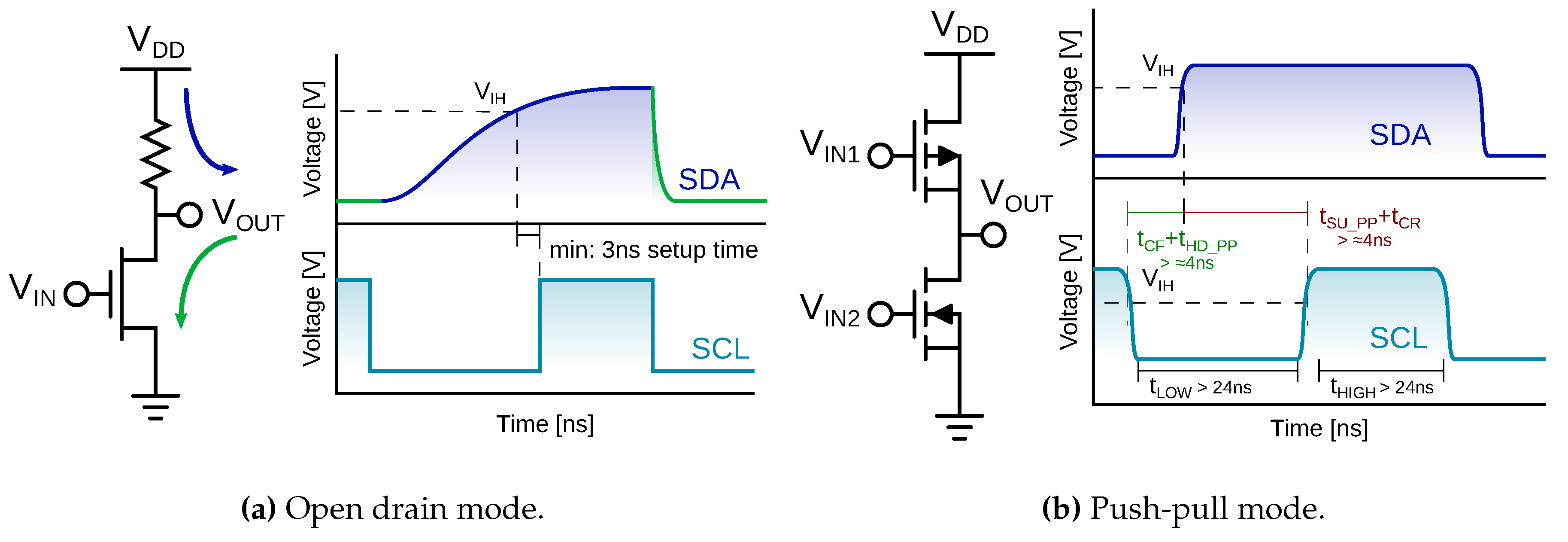
Figure 2.
Representation of the arbitration process during the broadcast address phase.
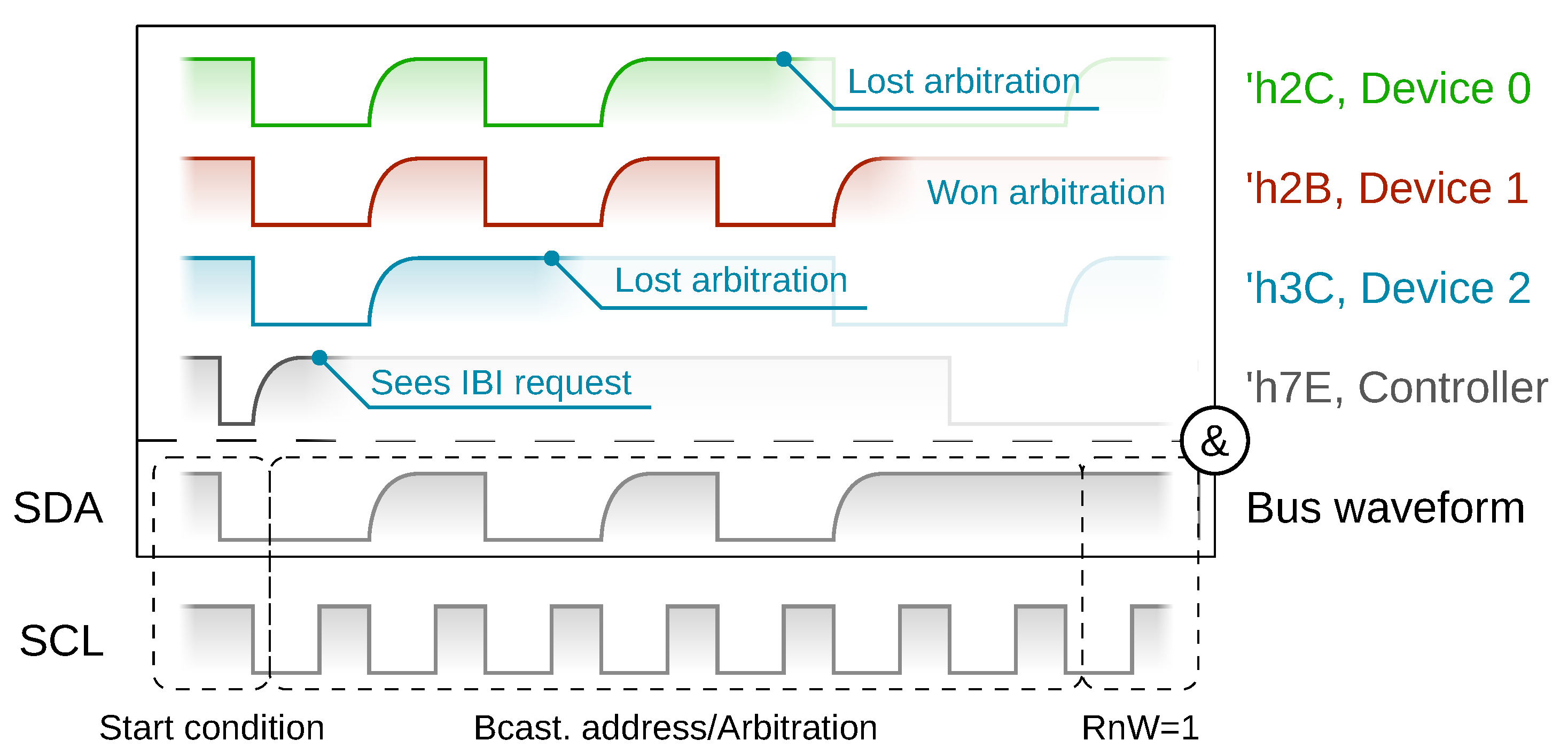
Figure 3.
General controller architecture.
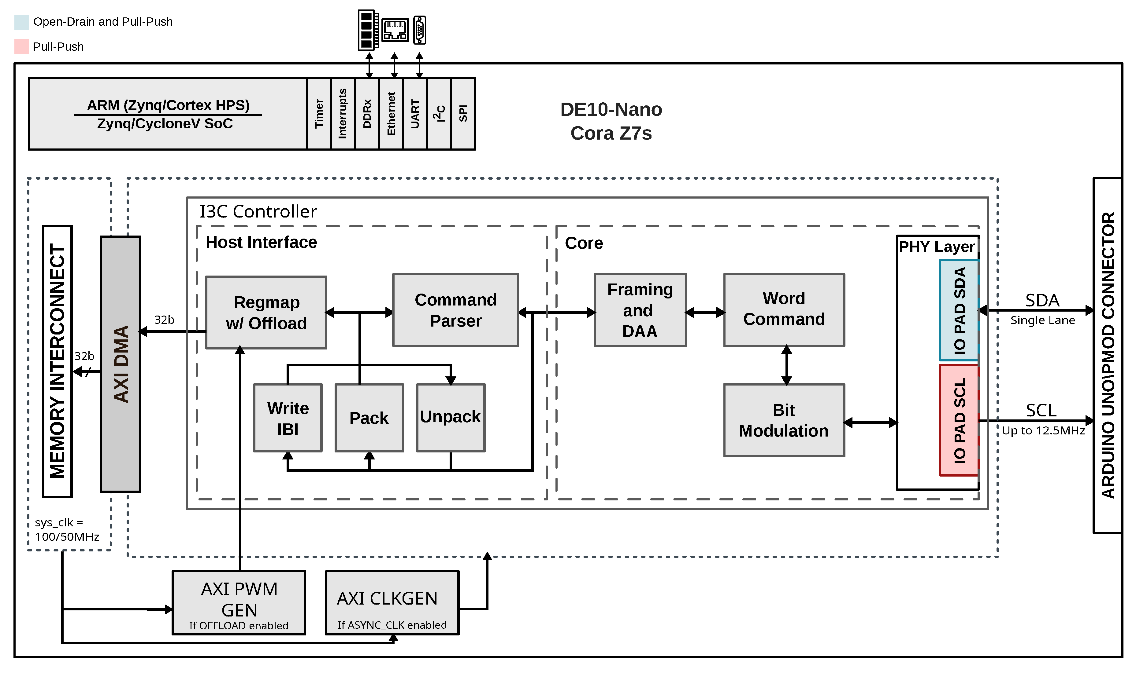
Figure 4.
CCC DISEC 0x0B at 12.5MHz.
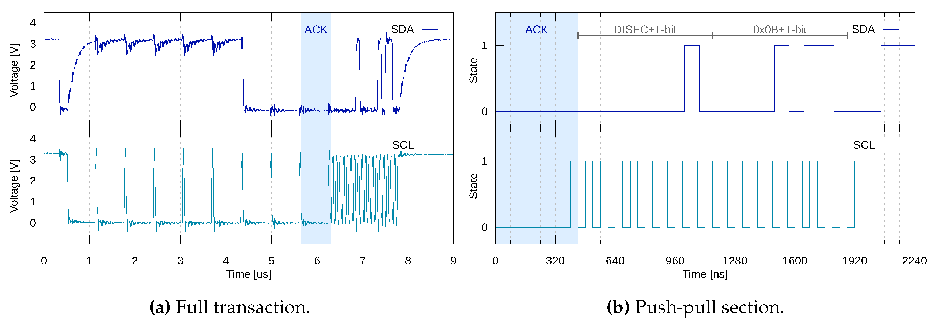
Figure 5.
i3c IBI transaction, Dynamic Address=0x32, Bus Characteristics Register, bit 2=1.
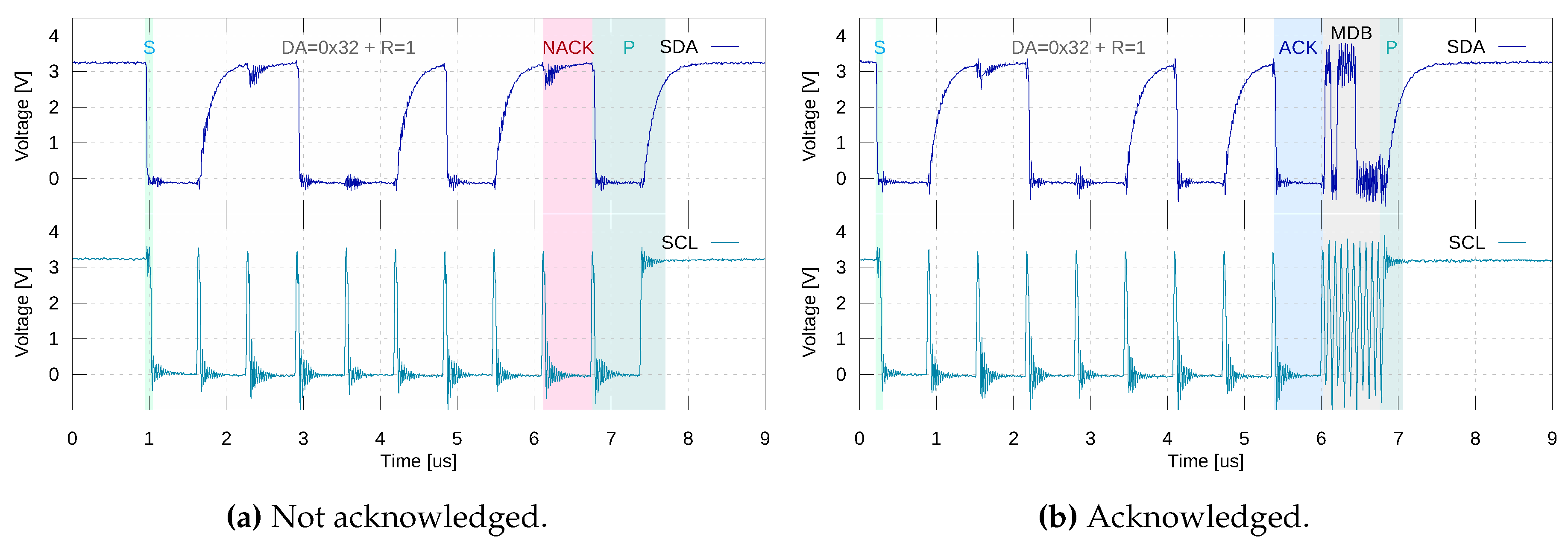

Table 1.
Command 0 descriptor.
| Name | Range | Description |
| 31:23 | Reserved. | |
| Is CCC | 22:22 | Indicate if it is a CCC transfer (1) or not (0). |
| Bcast. header | 21:21 | Include broadcast header in private transfer (1) or not (0). |
| Sr | 20:20 | Yield a Repeated Start (1) or Stop (0) at the end of the transfer. |
| Buffer length | 19:08 | Unsigned 12-bits payload length, direction depends on rnw value. |
| DA | 07:01 | 7-bit device address (don’t care in broadcast mode). |
| RnW | 00:00 | If should retrieve data from device (1) or not (0). |
Table 2.
Command 1 descriptor, CCC instruction.
| Name | Range | Description |
| Type | 07:07 | Direct (1) or broadcast (0), except SETXTIME and VENDOR. |
| ID | 06:00 | CCC to transfer; identifier matches the payload to be sent in the bus. |
Table 3.
New Linux kernel source files.
| File | Description |
| adi-i3c-controller.c | I3C Controller driver, methods for the I3C Linux abstractions. |
| dev/dev_core.c | Test device driver, agnostic to the communication protocol. |
| dev/dev_i3c.c | Test device driver, specific to the I3C variant. |
| adi,adi-i3c-controller.yaml | I3C Controller driver documentation. |
| -*-dev-i3c.dts | Devicetree file (template). |
Table 4.
Resource utilization (Cora Z7s with I3C+DMA vs SPI+DMA).
| I3C | I3C | SPI | |
| Resource | Utilization % | Utilization | Utilization |
| LUT | 22.45 | 3234 | 2369 |
| LUTRAM | 14.15 | 849 | 131 |
| FF | 10.92 | 3145 | 3645 |
| BRAM | 4.0 | 2 | 4.5 |
| IO | 10.0 | 10 | 13 |
| BUFG | 3.12 | 1 | 3 |
| MMCM | 0 | 0 | 1 |
Disclaimer/Publisher’s Note: The statements, opinions and data contained in all publications are solely those of the individual author(s) and contributor(s) and not of MDPI and/or the editor(s). MDPI and/or the editor(s) disclaim responsibility for any injury to people or property resulting from any ideas, methods, instructions or products referred to in the content. |
© 2024 by the authors. Licensee MDPI, Basel, Switzerland. This article is an open access article distributed under the terms and conditions of the Creative Commons Attribution (CC BY) license (http://creativecommons.org/licenses/by/4.0/).
Copyright: This open access article is published under a Creative Commons CC BY 4.0 license, which permit the free download, distribution, and reuse, provided that the author and preprint are cited in any reuse.


