
Submitted:
15 December 2024
Posted:
16 December 2024
You are already at the latest version
Abstract
This research introduces a polarization-insensitive metasurface (MS) capable of wide reception angles, featuring an array of wheel resonators designed for energy harvesting applications at 5 GHz. The symmetrical structure of the proposed resonator enables it to be highly insensitive to the polarization of the incident wave, ensuring efficient absorption of electromagnetic (EM) power and significantly reducing reflections. This allows for the majority of the captured energy to be delivered to resistor loads. Simulation results demonstrate that the proposed MS structure achieves a higher absorptivity for various polarizations and incident angles. Furthermore, a near-unity harvesting efficiency exceeding 94% is obtained regardless of the polarization of the incident wave under normal incidence at 5 GHz. Moreover, a higher harvesting efficiency is observed across various incident angles for TE and TM polarization. A 5×5-unit cell array of the proposed MS structure is fabricated and experimentally tested to validate the concept. The simulation and experimental results exhibit good agreement. The proposed harvester demonstrates superior absorptivity and harvesting efficiency across various polarizations and incident angles, making it a strong candidate for energy harvesting systems in wireless sensor networks.
Keywords:
electromagnetic energy harvesting
; metasurface
; polarization-insensitive
; wide-angle
; higher conversion efficiency
1. Introduction
The emergence of 5G technology has revolutionized connectivity, offering faster speeds, reduced latency, and increased capacity. As a result, it has facilitated the widespread adoption of low-power intelligent devices, such as IoT devices, sensors, and implantable medical devices. These compact and energy-efficient devices are now integral to various aspects of our lives. Furthermore, the technology enables wireless power supply to these devices through energy harvesting, a process that captures EM energy from the environment and converts it into DC power [1,2,3,4]. The EM energy harvesting in the microwave regime has garnered significant attention due to its advantageous characteristics, such as low cost, compact size, and potential for long-range power transfer [5]. Metamaterials represent cutting-edge technologies in manipulating EM waves, providing exceptional control over wave propagation, reflection, and absorption. These specially designed materials, distinguished by their subwavelength structural features, exhibit distinct EM properties not observed in natural materials, opening up new possibilities for innovative applications in energy harvesting [6,7].
MS is a 2-D metamaterial structure consisting of subwavelength elements arranged periodically within a specific area with a thickness less than the wavelength of the EM waves it interacts with [8]. MSs offer unique capabilities in manipulating EM fields, making them suitable for various applications such as antenna design [9], cloak [10], absorber [11]–[17], wireless power transfer (WPT), and energy harvesting [16,17,18,19,20] Recently, MSs have gained attention as energy collectors for energy harvesting applications, replacing conventional antennas due to their advantageous properties, including multi-polarization and wide coverage angle. The performance of an MS critically depends on the geometry of the structure and the periodic arrangement of unit cells. The metal-dielectric-metal (MDM) MS structure is exceptionally efficient for energy harvesting and can be adjusted to enhance harvesting effectiveness at particular frequencies. The top metallic resonator is connected to the ground plane through an optimal resistor load through a harvesting port (Via), ensuring efficient energy transfer and impedance matching while minimizing energy loss and maximizing efficiency [21, 22]. The MS-based energy harvesting performance has been optimized with various works, including improving the harvesting bandwidth [23, 24], enhancing the harvesting efficiency [24], and wide-band[23,25]. A rectifying MS array where each array element was connected to a rectifier circuit was proposed in [26,27,28]. Furthermore, to increase the overall conversion harvesting efficiency, the MS array elements were connected to a single rectifier circuit using a corporate feed network [29,30,31,32]. In addition, multi-band MS harvesters were designed to capture microwave radiation from multiple sources across different frequency ranges [33,34,35].
To optimize energy harvesting, the MS-based energy harvesting is equipped with multi-polarization capabilities, enabling it to capture EM waves irrespective of their polarization [36,37,38,39]. The polarization-insensitive MS harvesters based on the split ring resonator (SRR) were reported in [39,40,41,42], where each unit cell of the MS array is connected to optimal resistor loads using four Vias. The presence of four vias adds complexity and manufacturing challenges and distributes the received EM power into four loads, complicating subsequent power synthesis. In [45], a polarization-insensitive MS-based energy harvesting was designed using a butterfly-shaped closed-ring resonator. However, a higher harvesting efficiency was observed with a resistor load of approximately 3 KΩ, which complicated the design of the power-combining network and restricted its applicability in real-world harvesting systems. Furthermore, in some recent work, MS structures loaded with resistor loads placed between two sections of the resonator were designed for energy-harvesting applications [44,45,46]. It is worth noting that in these configurations, the resistors were not connected to the ground. As a result, replacing them with rectifying circuits or combining networks presents a challenge.
This study presents a polarization-insensitive and wide-angle metasurface structure comprising an array of symmetric wheel resonators designed to resonate at 5 GHz for energy harvesting applications. The proposed MS harvester has two resistor loads representing the input impedance of the power-combining circuit in the complete harvesting system. Simulation results show that the proposed MS can efficiently absorb incoming EM wave power and deliver the maximum absorbed energy to the loads with a near-unity harvesting efficiency (exceeding 90%), regardless of the polarization of the incident wave under normal incidence. Furthermore, it can capture incident EM power and deliver it to the loads with higher harvesting efficiency under various incident angles. Each unit cell of the proposed MS array has only two terminals, simplifying the power-combining network, in contrast to designs in [39,40,41], where each cell is connected to four terminals. Additionally, the maximum harvesting efficiency is achieved at an impedance load of 50 Ω, whereas in [45], the resistance value of the terminals is 3 KΩ, requiring a more complex power-combining network. It is important to emphasize that in this research, similar to early works on the design of harvesters [33,34,36,38,40,42] the loss resulting from the power combining network and rectifying circuits has not been taken into account.
2. Metasurface Unit Cell Design
In this study, the MS unit cell is designed based on the wheel resonating structure, as depicted in Figure 1. It consists of an MDM structure, with the top metallic layer functioning as a resonant and the bottom metallic layer as a ground plane. A dielectric substrate made of Rogers RO4003C with a dielectric constant of 3.55, tangent loss of 0.0027, and a thickness of h= 1.524 mm is utilized to minimize energy loss. Furthermore, copper with a conductivity of and thickness of is used to fabricate the top metallic resonator, vias, and ground plane. Two vias are positioned on the two sides of the wheel resonator. Two annular gaps are opened around the vias at the ground plane to accommodate a load resistance of 50 Ω.
Two resistor loads connect the metallic resonator to the ground plane through these vias. This arrangement ensures that the induced current can smoothly deliver to the load, allowing the top metallic resonator to receive incident waves at different incident and polarization angles. The wheel resonator structure is chosen for its simplicity and compact size, making it ideal for integrating energy harvesters into small electronic devices or wearable technology. Additionally, its rotational symmetric design makes it polarization-insensitive. Moreover, it offers enhanced EM coupling, leading to high efficiency at the desired frequency. The optimized parameters of the proposed MS unit cell harvester are listed in Table 1.
The equivalent RLC circuit model is presented to analyze the absorption mechanism of the proposed MS structure, as shown in Figure 2. The equivalent circuit includes two sections. Section 1 represents the free space incident wave, which had an impedance of . Section 2 is a metasurface structure. The input impedance of the proposed MS harvester can be described as
where , , represent the equivalent inductance and capacitance of the top metallic wheel resonator and the split (g). represents the inductance of the metallic ground plane and vias. is the harvesting load and is a capacitance between the via and ground plane. The substrate between the MS resonator and ground plane can be modeled as a transmission line with an impedance of . The lumped element values in the equivalent circuit can be estimated using the microstrip line model [49]. Then, the estimated values for effective L, C, and R, are optimized using the tuning function in the Keysight Advanced Design System (ADS) simulator.
3. Results and Discussion
3.1. Impact of structure parameters
- A.
- Normal incident analysis
The MS unit cell's functionality was confirmed through numerical simulations using CST Microwave Studio. Periodic boundary conditions and Floquet ports were utilized, with a plane wave incident along the z-axis. The return loss of the proposed MS unit cell is calculated using CST Microwave Studio and compared with the results obtained from aligned EM simulation software Advanced Design System (ADS), as shown in Figure 3a. From Figure 3a, theparameter is lower than -30 dB for TE and TM polarization under normal incidence, indicating optimal performance with the minimal reflection of incident EM waves in free space. Furthermore, a comparison between the results from ADS and those simulated in CST demonstrated a reasonable agreement, validating the equivalent circuit model of the structure. The symmetrical design of the proposed MS unit cell makes it insensitive to polarization. Therefore, the parameter for TE polarization is calculated. In addition, the normalized input impedance of the MS unit cell, terminated with 50 Ω resistor loads, is analyzed, as depicted in Figure 3b. At the resonant frequency of 5 GHz, the real part of the normalized impedance almost equals 1, indicating a strong impedance match between the MS unit cell and free space. This results in efficient absorption of the incident wave, especially when 50 Ω resistor loads terminate the unit cell.
To verify the polarization insensitivity for the proposed MS unit cell, the absorption ratio under normal incidence for TE and TM polarization is calculated as follows
where and are the reflection and transmission coefficients.
The back metallic layer of the structure acts as a physical barrier, effectively preventing transmission and resulting in an almost zero transmission coefficient. So, the absorptivity can be described as
The minimum reflection can be achieved when the impedance of the MS structure is well-matched with the impedance of free space, resulting in maximizing the absorptivity.
Figure 3c illustrates the absorption ratios for the MS unit cell under TE and TM polarizations. It achieves over 98% absorption peaks for both TE and TM polarizations at 5 GHz under normal incidence.
However, it's not enough to just reduce reflected waves; transferring the maximum absorbed power to the resistor load is also important for effectively collecting and reusing the incident EM waves. Therefore, the efficiency of power transmission to the resistor load can be calculated as follows
where and represent the power delivered to the load and power incident into the MS area. Figure 3d illustrates the conversion efficiency of the proposed MS unit cell for TE and TM polarizations. A higher harvesting efficiency peak of about 94% is achieved for both TE and TM polarizations under normal incidence.
The power loss was thoroughly studied to assess the energy harvesting capabilities of the proposed design. A full-wave simulation was performed to investigate the distribution of dissipated power within the unit cell across a wide frequency range. Figure 4 illustrates the power absorbed by the MS and the power losses in the resistor load, metal, and dielectric substrate (Rogers) when the incident EM waves propagate along the z-axis. This provides a comprehensive insight into the distribution and dissipation of power within the unit cell. The power losses in the proposed MS unit cell were analyzed using CST Microwave Studio with Frequency-domain solver. Floquet ports with a fixed incident power value of is used to excite the MS design. The simulation results for TE mode were provided because the MS unit cell is symmetrical and insensitive to polarization. As shown in Figure 4, the MS structure absorbs the most incident power, which is mainly concentrated in the resistor loads, achieving approximately 94% at 5 GHz. The power dissipated into the metal, and Rogers substrate material is almost negligible. This indicates that the proposed MS structure effectively collects the incident power.
To demonstrate the polarization-insensitive abilities of the MS structure, the analysis of its electric field (E-field), magnetic field (H-field), and surface current for both TE and TM polarization at the resonance frequency of 5 GHz is conducted. The results of this analysis are presented in Figure 5 and Figure 6. Figure 5 illustrates the electrical properties of the MS unit cell at 5 GHz for TE polarization under normal incidence. The electric field distribution in Figure 5a reveals that the EM resonance primarily occurs along the y-axis of the unit cell, with a clear accumulation of charge along this axis that then passes through the harvesting port (via) to the grounded resistor load (R1). The magnetic field (H-field) distribution, as depicted in Figure 5b, is more concentrated along the x-axis. The current surface distribution at 5 GHz for normal incidence is shown in Figure 5c, which reveals a current flow on both the inner and outer sides of the unit cell. This is evident from the intense red coloration observed across the wheel resonator. However, the magnitude of the electric current is more concentrated on the inner side of the wheel resonator than on the outer side. Additionally, the surface current is antiparallel at the top resonator and flows through the via hole (Via_2) to dissipate into the resistor load (R2). The power distribution at the resonant frequency of 5 GHz is shown in Figure 4d. The power absorbed by the MS unit cell is primarily concentrated in the resistor load (R2), making the proposed MS structure highly suitable for energy harvesting applications.
Figure 6 displays the electrical properties of the proposed MS structure at 5GHz for TM polarization with normal incidence, including E-field, H-field, current surface, and power flow. As shown in Figure 6a, the E-field distribution is most concentrated along the x-axis, then flows through the via hole to resistor load (R2). The H-field is distributed along the resonator, and it is more concentrated on the inner side of the wheel resonator, as seen in Figure 6b. Accordingly, Figure 6c shows the current surface distribution. It is clear that the current surface is antiparallel at the top resonator and then flows through the harvesting hole (Via_1) into the resistor load (R1). Finally, the power flow distribution at 5 GHz is shown in Figure 6d. It is noted that the most power absorbed by the top resonator is delivered to the resistor load (R1), resulting in high harvesting efficiency.
For additional verification, the conversion efficiency of the proposed MS structure in capturing EM power was assessed by adjusting the resistor load values. Figure 7 presents the harvesting efficiency of the proposed MS harvester as the resistor load value is varied from 50 Ω to 200 Ω. It is evident that an increase in the resistor load value shifts the harvesting efficiency peak to the lower frequency band due to the increase in the inductive and capacitive reactance. The maximum harvesting efficiency at 5 GHz is obtained when the resistor load value equals 50 Ω, indicating optimal impedance matching between the MS harvester and free space.
- B.
- Polarization angle analysis
The polarization-insensitive behavior of the proposed MS structure is analyzed by varying the polarization angle . Figure 8 shows the harvesting efficiency for the proposed MS array at normal incidence when the polarization angle varies from to for both TE and TM polarizations. The harvesting efficiency is examined and calculated using Equation (4). As shown in Figure 8, the harvesting efficiency peak of 94% is achieved at various polarization angles up to for both TE and TM polarizations under normal incidence. Furthermore, the proposed MS harvester can maintain a consistent harvesting efficiency even with changes in polarization angles, showing that the MS structure is polarization-independent.
- C.
- Incident angle analysis
In various scenarios, EM waves do not approach perpendicularly but arrive at an angle relative to the MS resonator. Therefore, it is crucial to analyze how different modes of obliquely incident EM waves impact the absorption performance of the MS. The reflection coefficient for TE and TM polarization under oblique incidence can be described as follows
where and are the impedance of the MS resonator and free space, and and are the incident and transmission angles, respectively. Based on equations (5) and (6), the reflection coefficient changes as the incident angle varies. The absorption spectra of the proposed MS harvester are examined by varying the incident angle from up to for both TE and TM polarization, as shown in Figure 9. As can be seen in Figure 9a, it is evident that for TE polarization, the absorption spectrum remains consistent within the range of to , exhibiting an absorption ratio of 98%. When the incident angle increases form to , the absorption peak slightly shifted to a higher frequency. When and , the absorption ratio is over 96% at 5.04 GHz and 5.09 GHz, respectively. At the absorption ratio of over 88% is observed at 5.14 GHz. Moreover, when the incident angle changes to , the absorption ratio is decreased to 57% at 5.22 GHz. The decrease in absorption can be attributed to the MS absorber's ability to more easily achieve electrical resonance in response to external EM waves compared to its more challenging magnetic resonance. As the incident angle increased in the TE mode, the magnetic field component along the y-direction gradually decreased, reducing the magnetic flux. This caused a misalignment between the magnetic and electrical resonances, resulting in an impedance mismatch within the MS unit cell and consequently posing challenges in maintaining high absorption levels (See Figure 9a).
For TM polarization, the absorption spectrum over 97% is observed for to , as shown in Figure 9b. The absorption peak over 97% and 95% is obtained at 5.1 GHz and 5.2 GHz when the and respectively. Furthermore, an absorption peak of 90% is obtained at 5.34 GHz at . In the case of the incident TM mode EM wave, it was observed that the magnetic field was consistently aligned with the y-direction. This consistent alignment resulted in a stable response of the MS to the magnetic field, which allowed for strong magnetic resonance at different incident angles, thereby maintaining high levels of absorptance [50].
In addition, the harvesting efficiency of the proposed MS unit cell is computed for various incident angles from to for TE and TM polarization, as shown in Figure 10. For TE polarization, the harvesting efficiency peak of about 94% is achieved for the incident angles of to , as shown in Figure 10a. At , the harvesting efficiency of over 91% is observed. When the incident angle increases to and , the harvesting efficiency is decreased to 86% and 74% at 5.15 GHz and 5.2 GHz, respectively. At , the harvesting peak of 54% is obtained at 5.19 GHz. In addition, the frequency deviation of 19 MHz is observed as the incident angle increases to for TE polarization. As the incident EM wave's angle increased in the TE mode, the magnitude of the magnetic field component H in the y-direction decreased progressively. Eventually, sustaining adequate flux to uphold a specific magnetic resonance became challenging. Consequently, the magnetic resonance failed to synchronize with the electrical resonance, resulting in an impedance mismatch within the MS absorber, leading to difficulties in maintaining high-efficiency levels (See Figure 10a).
For TM polarization, a 92% harvesting efficiency is obtained at as shown in Figure 10b. When the incident angle changes toand , the harvesting efficiency of 93% was observed at 5.08 GHz. A higher harvesting efficiency of over 90% is observed at 5.15 GHz and 5.21 GHz for the incident angles of and , respectively. Furthermore, the harvesting efficiency peak of over 85% is achieved at 5.36 GHz when . In the case of the TM mode incident EM wave, the magnetic field remained constantly oriented in the y-direction. This alignment ensured a uniform response from the MS to the magnetic field, which allowed for strong magnetic resonance at different angles while maintaining high levels of efficiency.
3.2. Experimental Verification
The proposed MS unit cell is initially validated through numerical simulations and tested experimentally by fabricating an MS harvester featuring a 5x5 unit cell array. The MS resonator array was printed on a Rogers RO4003C using the printed circuit board (PCB) technique. Each MS resonator is terminated by two ground resistor loads with a value of R= 50 Ω which functions to mimic the input impedance of a rectifier circuit, using two metallic vias with a diameter of 1 mm. The central unit cell is connected to one resistor load and VNA connector to measure the conversion efficiency. Figure 11 shows the fabricated MS harvester.
The experimental measurements were carried out to evaluate the conversion harvesting efficiency of the proposed MS harvester, as depicted in Figure 12. The experiment involved using a 5 dBm RF signal generator to transmit signal power to the horn antenna within a specified measurement band. The fabricated MS array was placed in the transmitting horn antenna’s far-field region and connected to a spectrum analyzer to measure the received power. To ensure the optimal excitation of the MS array by the plane wave within the far-field region, it is crucial to meticulously calculate the optimal separation between the transmitting antenna and the MS array. This calculation can be achieved using equation (7), as follows [51]
Where is the optimal separation between the horn antenna and the MS array, is the antenna’s aperture and is the wavelength.
The conversion harvesting efficiency can be calculated using equation (4). The power incident into the surface of the MS array can be obtained as follows
where is the horn antenna gain, is the power excited by the signal generator, which is 5 dBm, and is the separation distance between the horn antenna and the MS array. In addition, the effective array’s area is equal to the number of the array elements and the effective central unit cell area [44]. The MS structure's symmetry results in the total power received by one of the cells being the sum of the power delivered to both the horizontal and vertical resistors. In Figure 13, the measured harvesting efficiency for a 5×5 array of the proposed MS harvester is depicted as a function of frequency under various oblique incidence angles. As shown in the figure, a higher harvesting efficiency of over 86% and 83% is observed at 5.13 GHz and 5.22 GHz, respectively, when the incident angle is and . At the incident angle of , a 77% harvesting efficiency is achieved at 5.28 GHz. Moreover, as the incident angle increases, there is a decrease in harvesting efficiency and a slight shift in operating frequency due to the reduction in the magnetic flux.
Table 2 presents a comparison between the proposed MS harvester and similar previous works. The comparison includes the size of the cell, frequency deviation, and harvesting efficiency at the normal and oblique incidence. The harvester proposed in this research features a compact design with higher harvesting frequency over a wide, oblique incident angle with lower frequency deviation than those published earlier. Since, in [22] the compact design is achieved; however, the resistive load was optimized to 3.5 kΩ, which significantly differs from the input impedance of microwave feeding networks, which are crucial components of a rectenna. Consequently, this discrepancy limits the practical application in real-world harvesting systems, making the design of the necessary feeding network using microstrip technology highly challenging and virtually impractical.
4. Conclusions
This research presents a polarization-insensitive and wide-angle MS structure that employs a symmetrical wheel resonator for energy harvesting applications. The impedance of the MS cell is adjusted to match that of free space. This innovative MS-based energy harvester can efficiently capture energy from nearby EM waves and convert it into AC power, which can then be transferred to resistive loads through the vias. Simulation results reveal that when loaded with optimized 50 Ω resistors, the MS harvester absorbs over 98% of normally incident waves, regardless of polarization, and efficiently delivers almost all the absorbed power to the loads. Furthermore, it has been observed that the unit cell is not influenced by polarization when exposed to normal incident plane waves. It achieves a harvesting efficiency of approximately 94% for both TE and TM polarizations under normal incidence, 72% for TE polarization, and 90% for TM polarization at various incident angles up to . A 5×5 array of MS cells has been fabricated and tested, showing close agreement between measurement and simulation results. It's worth noting that under normal incidence, the measured harvesting efficiency is approximately 86%. Overall, this MS-based energy harvester exhibits promising features, such as high efficiency, polarization insensitivity, and wide-angle coverage, positioning it as a strong contender for energy harvesting applications.
Author Contributions
Conceptualization, A.A.G.A.; methodology, A.A.G.A.; software, S.Z.S.; validation, S.Z.S., and A.S.; formal analysis, A.A.G.A.; writing—original draft preparation, A.A.G.A.; writing—review and editing, N.O; A.A.A.S; M.M.B.S; visualization, A.A.A.S.; supervision, N.O.;M.M.B.S; S.Z.S. All authors have read and agreed to the published version of the manuscript.
Acknowledgments
The authors would like to express their gratitude for the support provided by Universiti Tun Hussein Onn Malaysia (UTHM) for this research.
Conflicts of Interest
The authors declare no conflict of interest.
References
- Nguyen, D.H.; Khazaei, J. Unified Distributed Control of Battery Storage With Various Primary Control in Power Systems. IEEE Trans. Sustain. Energy 2021, 12, 2332–2341. [Google Scholar] [CrossRef]
- Khanh, Q.V.; Hoai, N.V.; Manh, L.D.; Le, A.N.; Jeon, G. Wireless Communication Technologies for IoT in 5G: Vision, Applications, and Challenges. Wirel. Commun. Mob. Comput. 2022, 2022, 3229294. [Google Scholar] [CrossRef]
- Dangi, R.; Lalwani, P.; Choudhary, G.; You, I.; Pau, G. Study and Investigation on 5G Technology: A Systematic Review. Sensors 2021, 22, 26. [Google Scholar] [CrossRef]
- Heidari, H.; Onireti, O.; Das, R.; Imran, M. Energy Harvesting and Power Management for IoT Devices in the 5G Era. IEEE Commun. Mag. 2021, 59, 91–97. [Google Scholar] [CrossRef]
- Sarker, M.R.; Saad, M.H.M.; Olazagoitia, J.L.; Vinolas, J. Review of Power Converter Impact of Electromagnetic Energy Harvesting Circuits and Devices for Autonomous Sensor Applications. Electronics 2021, 10, 1108. [Google Scholar] [CrossRef]
- Metamaterials; Wiley: Hoboken, NJ, United States, 2006.
- Singh, G.; Ni, R.; Marwaha, A. A Review of Metamaterials and its Applications. Int. J. Eng. Trends Technol. 2015, 19, 305–310. [Google Scholar] [CrossRef]
- Holloway, C.L.; Kuester, E.F.; Gordon, J.A.; O'Hara, J.; Booth, J.; Smith, D.R. An Overview of the Theory and Applications of Metasurfaces: The Two-Dimensional Equivalents of Metamaterials. IEEE Antennas Propag. Mag. 2012, 54, 10–35. [Google Scholar] [CrossRef]
- Khanjarian, M.; Soleimani, M.; Nayyeri, V.; El Badawe, M.; Babazadeh, S.; Ramahi, O.M. A circularly polarized, high aperture efficiency metasurface antenna. Microw. Opt. Technol. Lett. 2021, 63, 3027–3034. [Google Scholar] [CrossRef]
- Xu, H.-X.; Hu, G.; Wang, Y.; Wang, C.; Wang, M.; Wang, S.; Huang, Y.; Genevet, P.; Huang, W.; Qiu, C.-W. Polarization-insensitive 3D conformal-skin metasurface cloak. Light. Sci. Appl. 2021, 10, 1–13. [Google Scholar] [CrossRef]
- Landy, N.I.; Sajuyigbe, S.; Mock, J.J.; Smith, D.R.; Padilla, W.J. Perfect Metamaterial Absorber. Phys. Rev. Lett. 2008, 100, 207402. [Google Scholar] [CrossRef]
- Shabanpour, J.; Beyraghi, S.; Ghorbani, F.; Oraizi, H. Implementation of conformal digital metasurfaces for THz polarimetric sensing. OSA Contin. 2021, 4, 1372–1380. [Google Scholar] [CrossRef]
- Shabanpour, J.; Beyraghi, S.; Oraizi, H. Reconfigurable honeycomb metamaterial absorber having incident angular stability. Sci. Rep. 2020, 10, 1–8. [Google Scholar] [CrossRef] [PubMed]
- Amer, A.A.G.; Sapuan, S.Z.; Othman, N.B.; Salem, A.A.; Al-Gburi, A.J.A.; Zakaria, Z. A Wide-Angle, Polarization-Insensitive, Wideband Metamaterial Absorber With Lumped Resistor Loading for ISM Band Applications. IEEE Access 2023, 12, 42629–42641. [Google Scholar] [CrossRef]
- Amer, A.A.G.; Sapuan, S.Z.; Nasimuddin, N. Efficient Metasurface Absorber for 2.4 GHz ISM-Band Applications. 2020 IEEE Student Conference on Research and Development (SCOReD); pp. 471–474.
- Bait-Suwailam, M.M.; Almoneef, T.S.; Alomainy, A. A Dual-Band Flexible Frequency-Reconfigurable Metamaterial Absorber using Modified Split-Ring Resonator. 2019 2nd IEEE Middle East and North Africa COMMunications Conference (MENACOMM). pp. 1–4.
- Al Ajm, H.Y.; Bait-Suwailam, M.M. A Wideband Electromagnetic Energy Harvester Design for Internet of Things (IoT) applications. 2022 International Conference on Electrical and Computing Technologies and Applications (ICECTA); pp. 378–381.
- Ojukwu, H.; Seet, B.-C.; Rehman, S.U. Metasurface-Aided Wireless Power Transfer and Energy Harvesting for Future Wireless Networks. IEEE Access 2022, 10, 52431–52450. [Google Scholar] [CrossRef]
- Amer, A.A.G.; Sapuan, S.Z.; Nasimuddin, N. Wide-Coverage Suspended Metasurface Energy Harvester for ISM Band Applications. 2021 IEEE 19th Student Conference on Research and Development (SCOReD); pp. 87–90.
- Amer, A.A.G.; Othman, N.; Sapuan, S.Z.; Alphones, A.; Salem, A.A. High-efficiency electromagnetic energy harvesting using double-elliptical metasurface resonators. PLOS ONE 2023, 18, e0291354. [Google Scholar] [CrossRef]
- Zhou, J.; Zhang, P.; Han, J.; Li, L.; Huang, Y. Metamaterials and Metasurfaces for Wireless Power Transfer and Energy Harvesting. Proc. IEEE 2021, 110, 31–55. [Google Scholar] [CrossRef]
- Almoneef, T.; Ramahi, O.M. A 3-DIMENSIONAL STACKED METAMATERIAL ARRAYS FOR ELECTROMAGNETIC ENERGY HARVESTING. Prog. Electromagn. Res. 2014, 146, 109–115. [Google Scholar] [CrossRef]
- Alavikia, B.; Almoneef, T.S.; Ramahi, O.M. Electromagnetic energy harvesting using complementary split-ring resonators. Appl. Phys. Lett. 2014, 104, 163903. [Google Scholar] [CrossRef]
- Almoneef, T.S.; Ramahi, O.M. Metamaterial electromagnetic energy harvester with near unity efficiency. Appl. Phys. Lett. 2015, 106, 153902. [Google Scholar] [CrossRef]
- Alavikia, B.; Almoneef, T.S.; Ramahi, O.M. Wideband resonator arrays for electromagnetic energy harvesting and wireless power transfer. Appl. Phys. Lett. 2015, 107, 243902. [Google Scholar] [CrossRef]
- Duan, X.; Chen, X.; Zhou, Y.; Zhou, L.; Hao, S. Wideband Metamaterial Electromagnetic Energy Harvester With High Capture Efficiency and Wide Incident Angle. IEEE Antennas Wirel. Propag. Lett. 2018, 17, 1617–1621. [Google Scholar] [CrossRef]
- He, Z.-J.; Deng, L.; Zhang, P.; Liu, Y.; Yan, T.; Liao, C.; Huang, S.; Qiu, L.-L.; Zhu, L. Wideband High-Efficiency and Simple-Structured Rectifying Metasurface. IEEE Trans. Antennas Propag. 2023, 71, 6202–6207. [Google Scholar] [CrossRef]
- Duan, X.; Chen, X.; Zhou, L. A metamaterial electromagnetic energy rectifying surface with high harvesting efficiency. AIP Adv. 2016, 6, 125020. [Google Scholar] [CrossRef]
- Lee, K.; Hong, S.K. Rectifying Metasurface With High Efficiency at Low Power for 2.45 GHz Band. IEEE Antennas Wirel. Propag. Lett. 2020, 19, 2216–2220. [Google Scholar] [CrossRef]
- Li, L.; Zhang, X.; Song, C.; Zhang, W.; Jia, T.; Huang, Y. Compact Dual-Band, Wide-Angle, Polarization- Angle -Independent Rectifying Metasurface for Ambient Energy Harvesting and Wireless Power Transfer. IEEE Trans. Microw. Theory Tech. 2020, 69, 1518–1528. [Google Scholar] [CrossRef]
- Xu, P.; Wang, S.-Y.; Geyi, W. Design of an effective energy receiving adapter for microwave wireless power transmission application. AIP Adv. 2016, 6, 105010. [Google Scholar] [CrossRef]
- El Badawe, M.; Almoneef, T.S.; Ramahi, O.M. A metasurface for conversion of electromagnetic radiation to DC. AIP Adv. 2017, 7. [Google Scholar] [CrossRef]
- Almoneef, T.S.; Erkmen, F.; Ramahi, O.M. Harvesting the Energy of Multi-Polarized Electromagnetic Waves. Sci. Rep. 2017, 7, 1–14. [Google Scholar] [CrossRef]
- Zhang, H.; Li, Y.; Hu, W.; Lu, Q.; Zhang, B.; Yang, L.Y. Polarization-Insensitive Electromagnetic Metamaterial Design for Multi-Band Energy Harvesting. IEEE Access 2023, 11, 143956–143963. [Google Scholar] [CrossRef]
- Amer, A.A.G.; Othman, N.; Sapuan, S.Z.; Alphones, A.; Hassan, M.F.; Al-Gburi, A.J.A.; Zakaria, Z. Dual-Band, Wide-Angle, and High-Capture Efficiency Metasurface for Electromagnetic Energy Harvesting. Nanomaterials 2023, 13, 2015. [Google Scholar] [CrossRef]
- Ghaderi, B.; Nayyeri, V.; Soleimani, M.; Ramahi, O.M. Pixelated Metasurface for Dual-Band and Multi-Polarization Electromagnetic Energy Harvesting. Sci. Rep. 2018, 8, 1–12. [Google Scholar] [CrossRef] [PubMed]
- Wei, Y.; Duan, J.; Jing, H.; Yang, H.; Deng, H.; Song, C.; Wang, J.; Qu, Z.; Zhang, B. Scalable, Dual-Band Metasurface Array for Electromagnetic Energy Harvesting and Wireless Power Transfer. Micromachines 2022, 13, 1712. [Google Scholar] [CrossRef]
- Ghaderi, B.; Nayyeri, V.; Soleimani, M.; Ramahi, O.M. Multi-polarisation electromagnetic energy harvesting with high efficiency. IET Microwaves, Antennas Propag. 2018, 12, 2271–2275. [Google Scholar] [CrossRef]
- Shang, S.; Yang, S.; Shan, M.; Liu, J.; Cao, H. High performance metamaterial device with enhanced electromagnetic energy harvesting efficiency. AIP Adv. 2017, 7. [Google Scholar] [CrossRef]
- Yu, F.; He, G.-Q.; Yang, X.-X.; Du, J.; Gao, S. Polarization-Insensitive Metasurface for Harvesting Electromagnetic Energy with High Efficiency and Frequency Stability over Wide Range of Incidence Angles. Appl. Sci. 2020, 10, 8047. [Google Scholar] [CrossRef]
- Zhong, H.-T.; Yang, X.-X.; Song, X.-T.; Guo, Z.-Y.; Yu, F. Wideband metamaterial array with polarization-independent and wide incident angle for harvesting ambient electromagnetic energy and wireless power transfer. Appl. Phys. Lett. 2017, 111. [Google Scholar] [CrossRef]
- Zhong, H.-T.; Yang, X.-X.; Tan, C.; Yu, K. Triple-band polarization-insensitive and wide-angle metamaterial array for electromagnetic energy harvesting. Appl. Phys. Lett. 2016, 109, 253904. [Google Scholar] [CrossRef]
- Zhong, H.; Yang, X. Broadband meta-surface with polarization-insensitive and wide-angle for electromagnetic energy harvesting. 2017 International Workshop on Antenna Technology: Small Antennas, Innovative Structures, and Applications (iWAT); pp. 125–128.
- Younesiraad, H.; Bemani, M. Broadband polarisation-independent metasurface electromagnetic energy harvester with high capture efficiency. IET Microwaves, Antennas Propag. 2020, 14, 1530–1536. [Google Scholar] [CrossRef]
- Zhang, X.; Liu, H.; Li, L. Tri-band miniaturized wide-angle and polarization-insensitive metasurface for ambient energy harvesting. Appl. Phys. Lett. 2017, 111, 071902. [Google Scholar] [CrossRef]
- Ullah, N.; Islam, S.; Hoque, A.; Yong, W.H.; Alrashdi, A.M.; Soliman, M.S.; Islam, M.T. An efficient, compact, wide-angle, wide-band, and polarization-insensitive metamaterial electromagnetic energy harvester. Alex. Eng. J. 2023, 82, 377–388. [Google Scholar] [CrossRef]
- Wei, Y.; Jing, H.; Deng, H.; Song, C.; Duan, J.; Wang, J.; Qu, Z.; Zhang, B. A dual-band, polarization-insensitive, wide-angle metasurface array for electromagnetic energy harvesting and wireless power transfer. Results Phys. 2023, 46. [Google Scholar] [CrossRef]
- Aldhaeebi, M.A.; Almoneef, T.S. Planar Dual Polarized Metasurface Array for Microwave Energy Harvesting. Electronics 2020, 9, 1985. [Google Scholar] [CrossRef]
- N. Marcuvitz, Waveguide handbook, no. 21. Iet, 1951.
- Zhou, Q.; Ma, W.; Wu, T.; Li, Y.; Qiu, Q.; Duan, J.; Li, J.; Jiang, L.; Zhou, W.; Gao, Y.; et al. Metasurface Terahertz Perfect Absorber with Strong Multi-Frequency Selectivity. ACS Omega 2022, 7, 36712–36727. [Google Scholar] [CrossRef] [PubMed]
- Johnson, R.; Ecker, H.; Hollis, J. Determination of far-field antenna patterns from near-field measurements. Proc. IEEE 1973, 61, 1668–1694. [Google Scholar] [CrossRef]
- Yu, F.; Yang, X.; Zhong, H.; Chu, C.; Gao, S. Polarization-insensitive wide-angle-reception metasurface with simplified structure for harvesting electromagnetic energy. Appl. Phys. Lett. 2018, 113, 123903. [Google Scholar] [CrossRef]
Figure 1.
Geometry of the MS unit cell structure (a) 3D view, (b) top view, (c) bottom view, and (d) schematic diagram of the MS array.
Figure 1.
Geometry of the MS unit cell structure (a) 3D view, (b) top view, (c) bottom view, and (d) schematic diagram of the MS array.
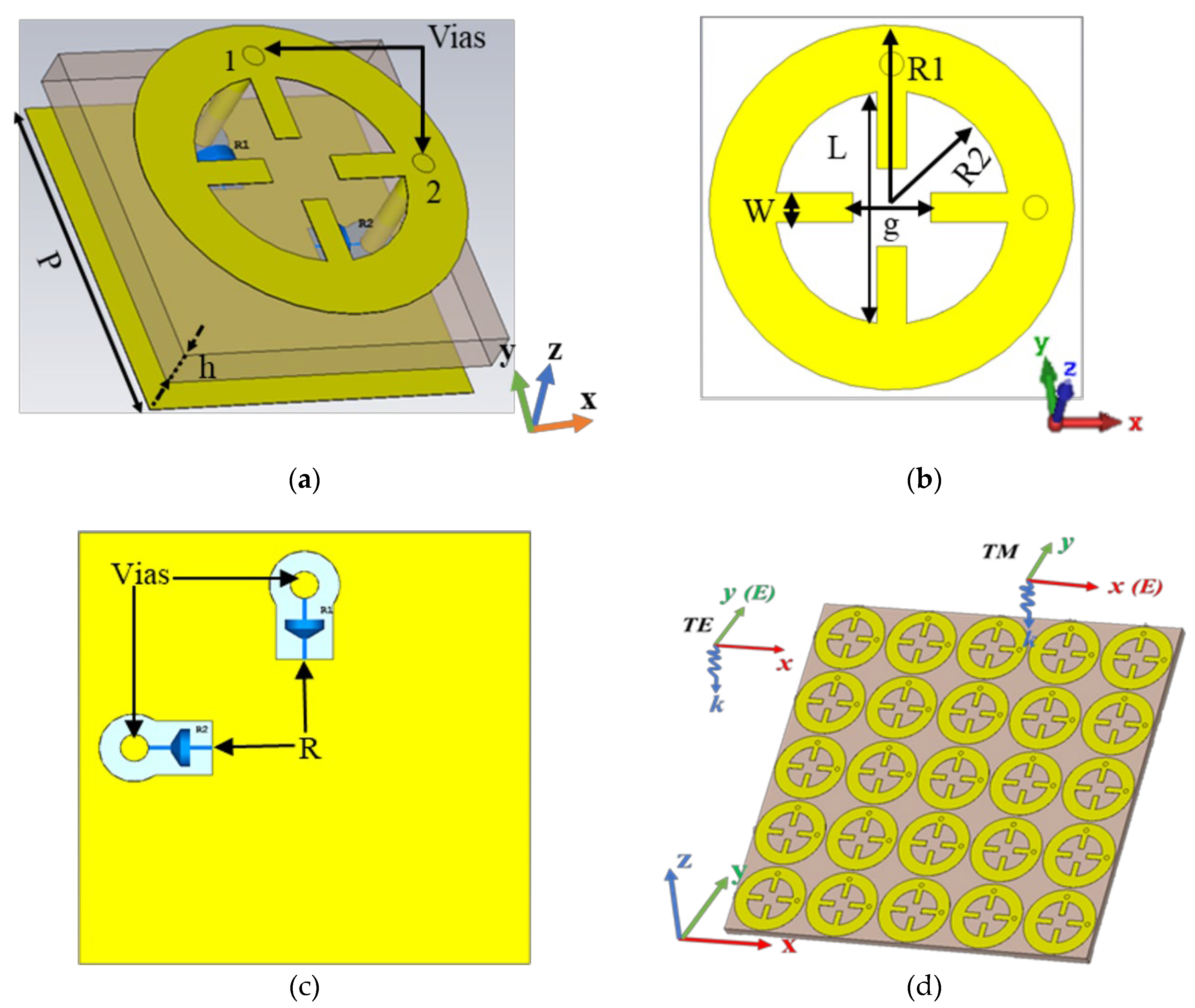
Figure 2.
Equivalent RLC circuit model. The parameters are , , , , and .
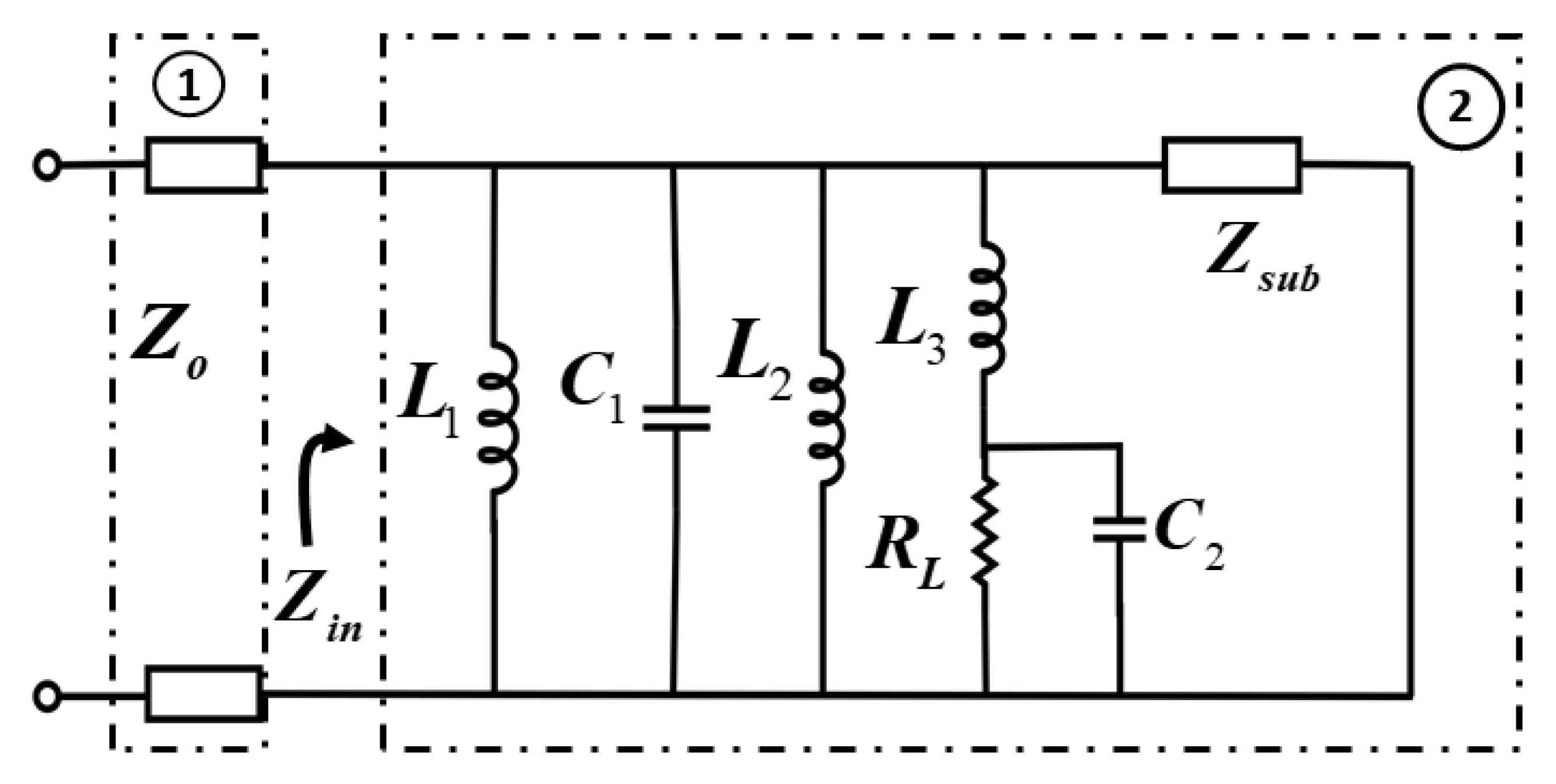
Figure 3.
(a) S-parameter, (b) input impedance, (c) absorption at TE and TM polarization, and (d) efficiency at TE and TM polarization under normal incidence.
Figure 3.
(a) S-parameter, (b) input impedance, (c) absorption at TE and TM polarization, and (d) efficiency at TE and TM polarization under normal incidence.
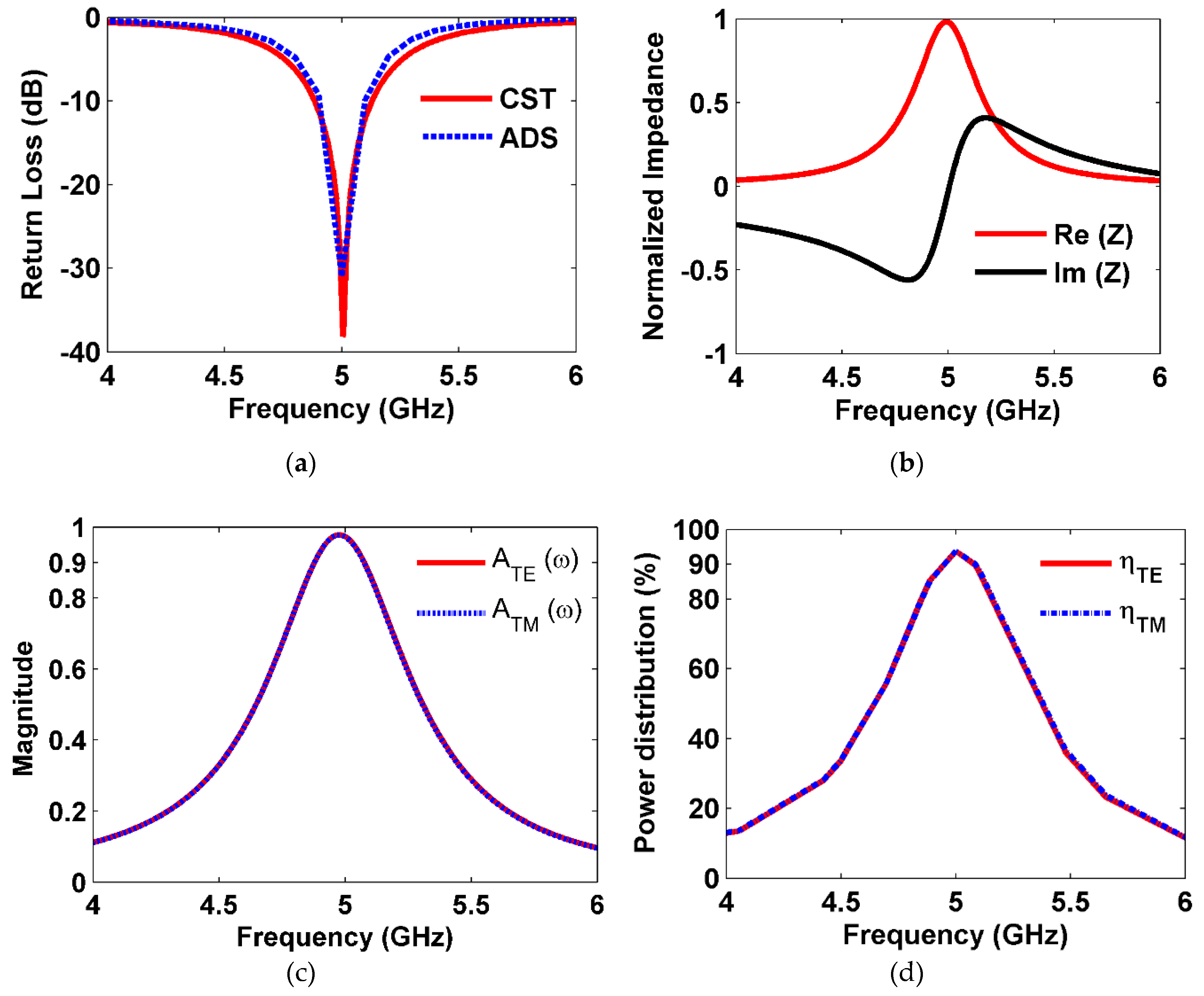
Figure 4.
Power distribution in the cell.
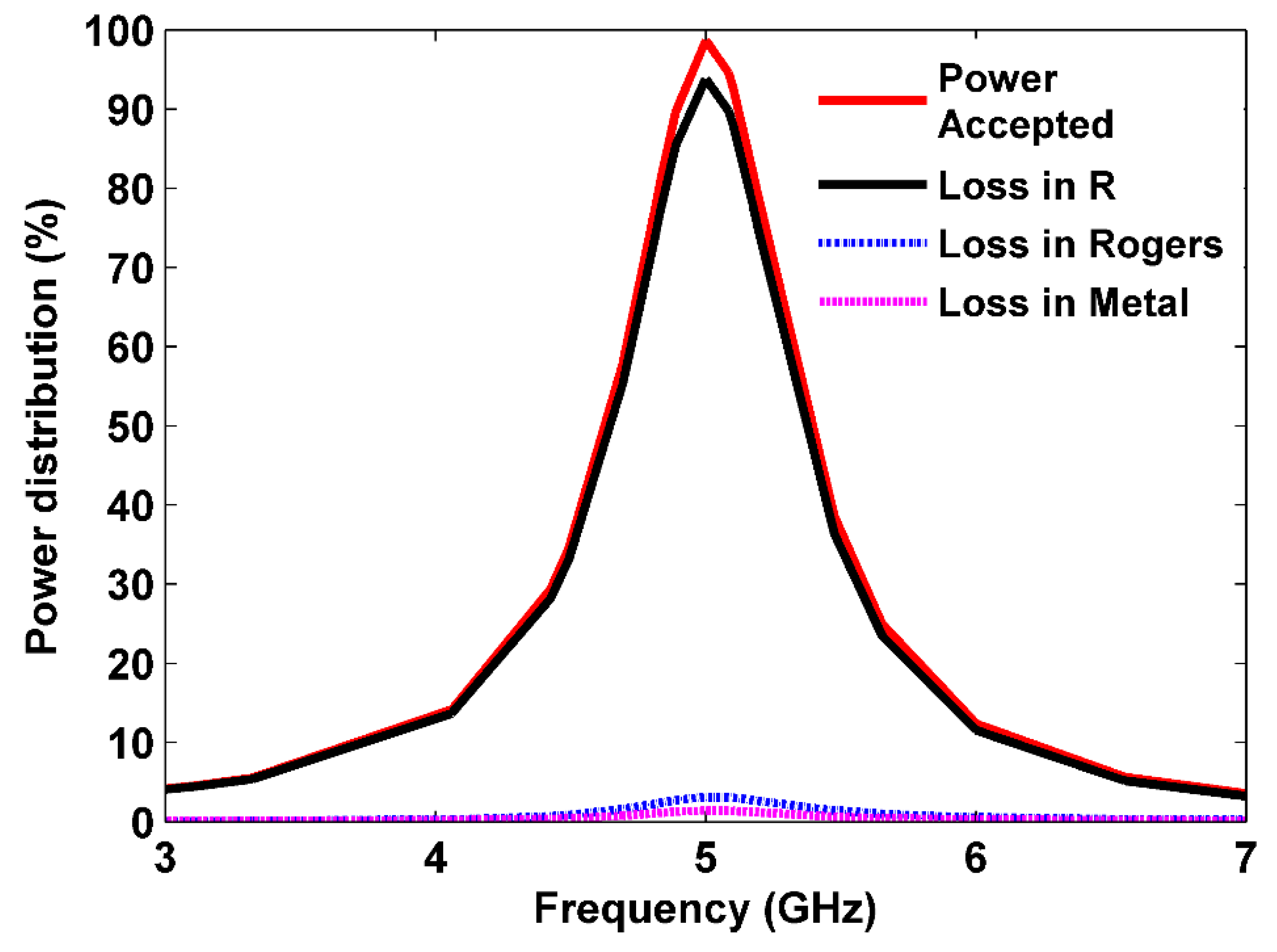
Figure 5.
(a) E-field, (b) H-field, (c) current surface, and (d) power flow at 5 GHz for TE polarization under normal incidence.
Figure 5.
(a) E-field, (b) H-field, (c) current surface, and (d) power flow at 5 GHz for TE polarization under normal incidence.
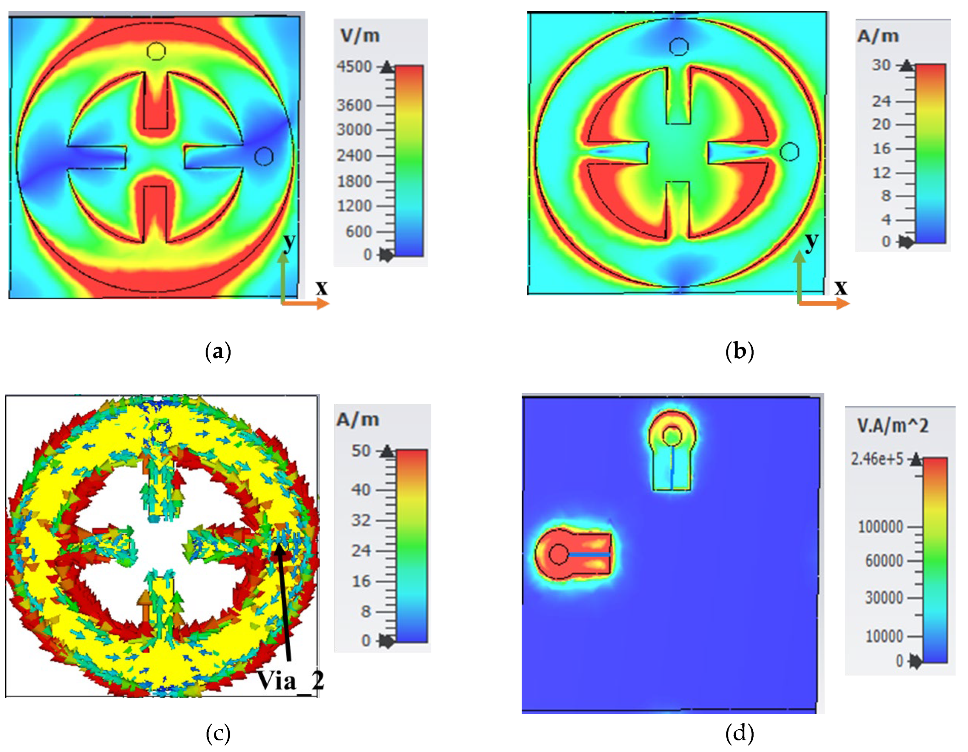
Figure 6.
(a) E-field, (b) H-field, (c) current surface, and (d) power flow at 5 GHz for TM polarization under normal incidence.
Figure 6.
(a) E-field, (b) H-field, (c) current surface, and (d) power flow at 5 GHz for TM polarization under normal incidence.
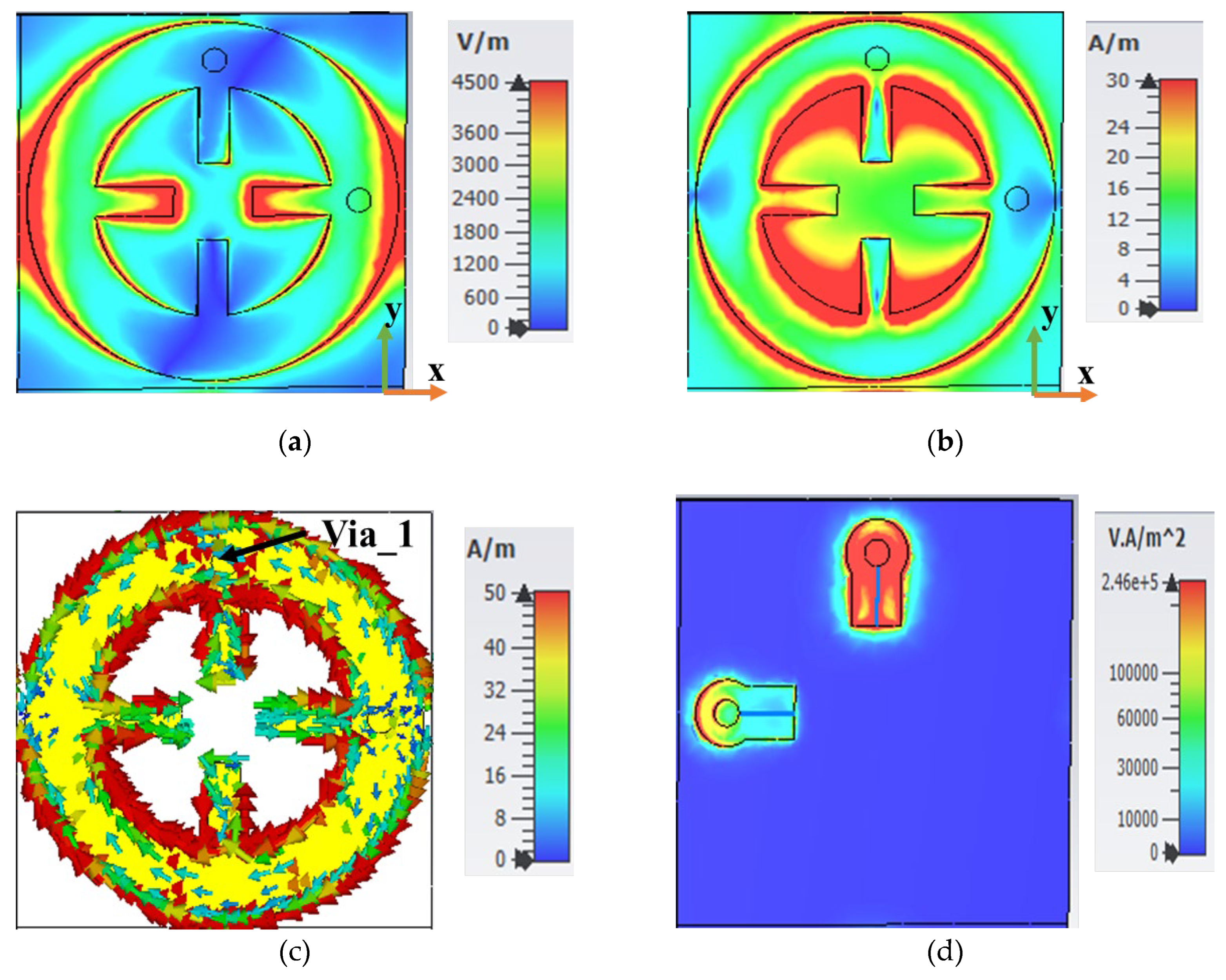
Figure 7.
Harvesting efficiency at different resistor load values.
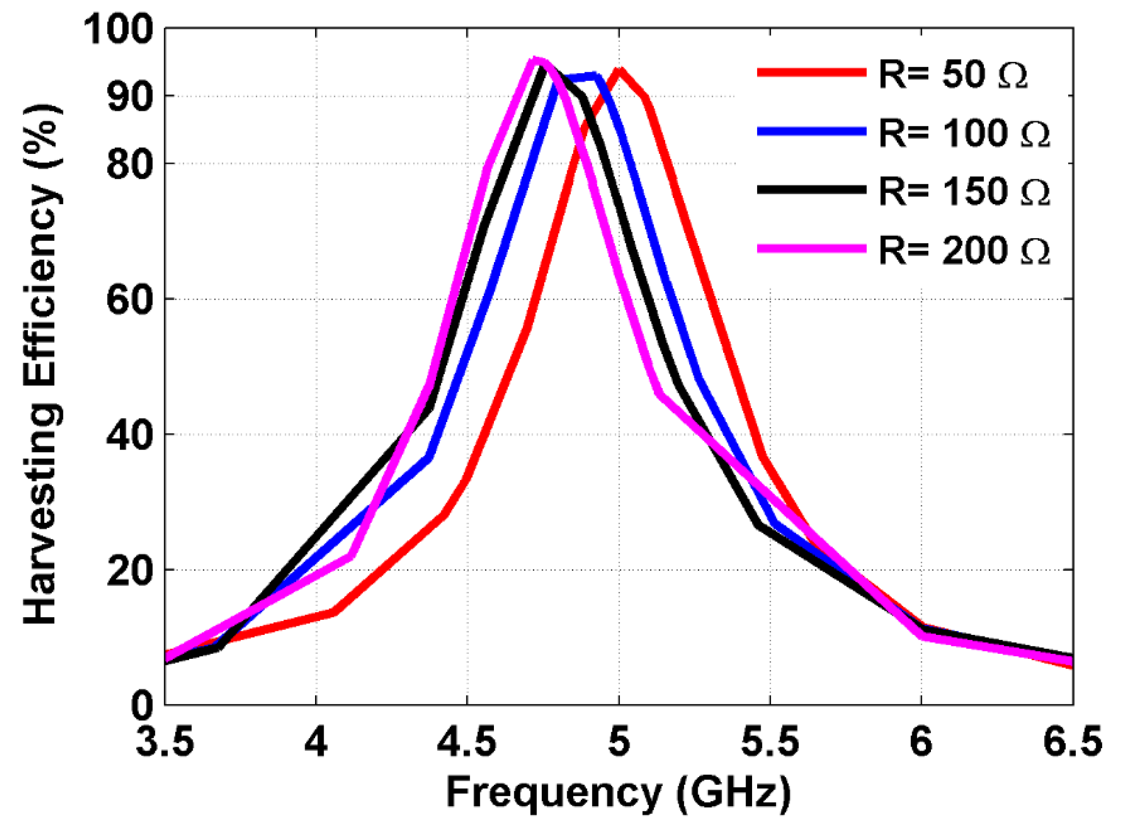
Figure 8.
Harvesting efficiency for different polarization angles for (a) TE polarization and (b) TM polarization.
Figure 8.
Harvesting efficiency for different polarization angles for (a) TE polarization and (b) TM polarization.
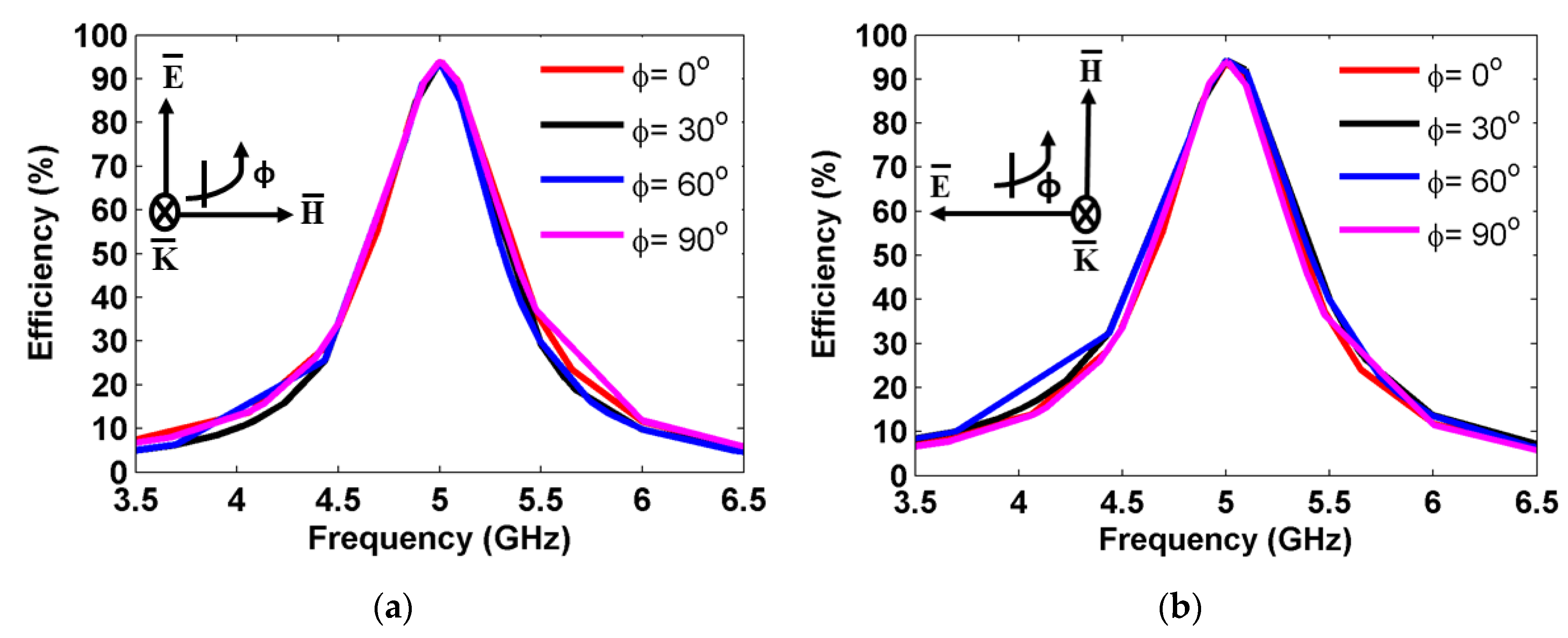
Figure 9.
Absorptivity for different incident angles (a) TE polarization and (b) TM polarization.
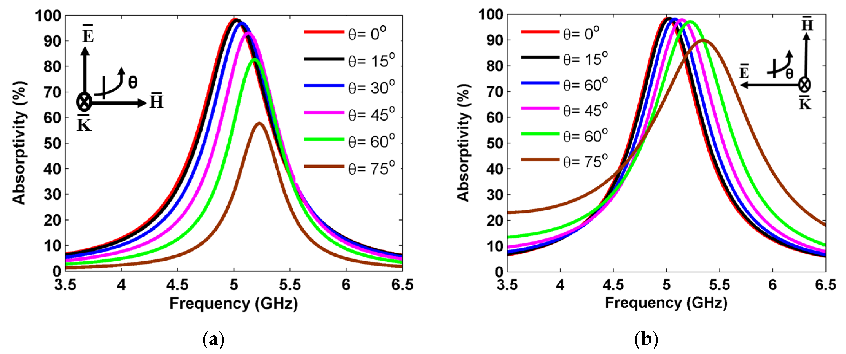
Figure 10.
Harvesting efficiency at different incident angles (a) TE polarization and (b) TM polarization.
Figure 10.
Harvesting efficiency at different incident angles (a) TE polarization and (b) TM polarization.
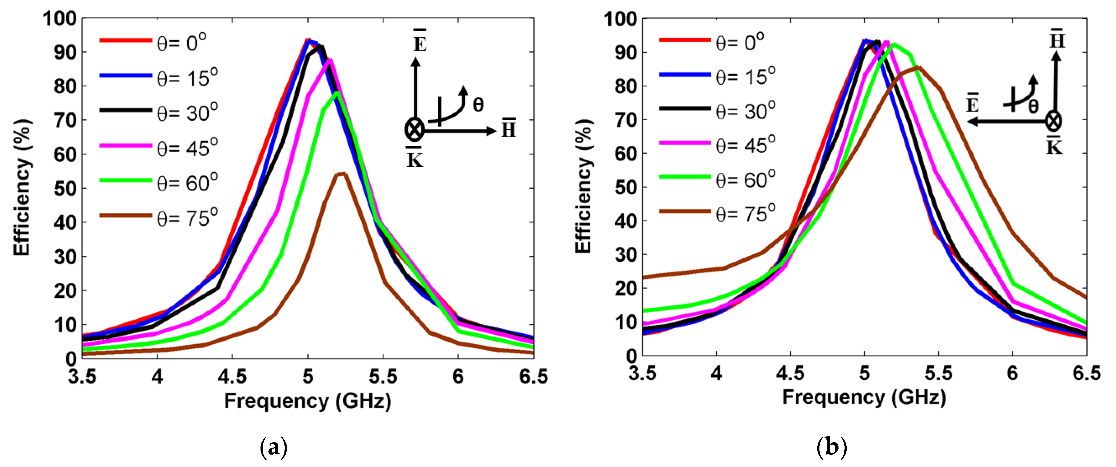
Figure 11.
Photo of fabricated MS harvester, (a) top view and (b) bottom view.
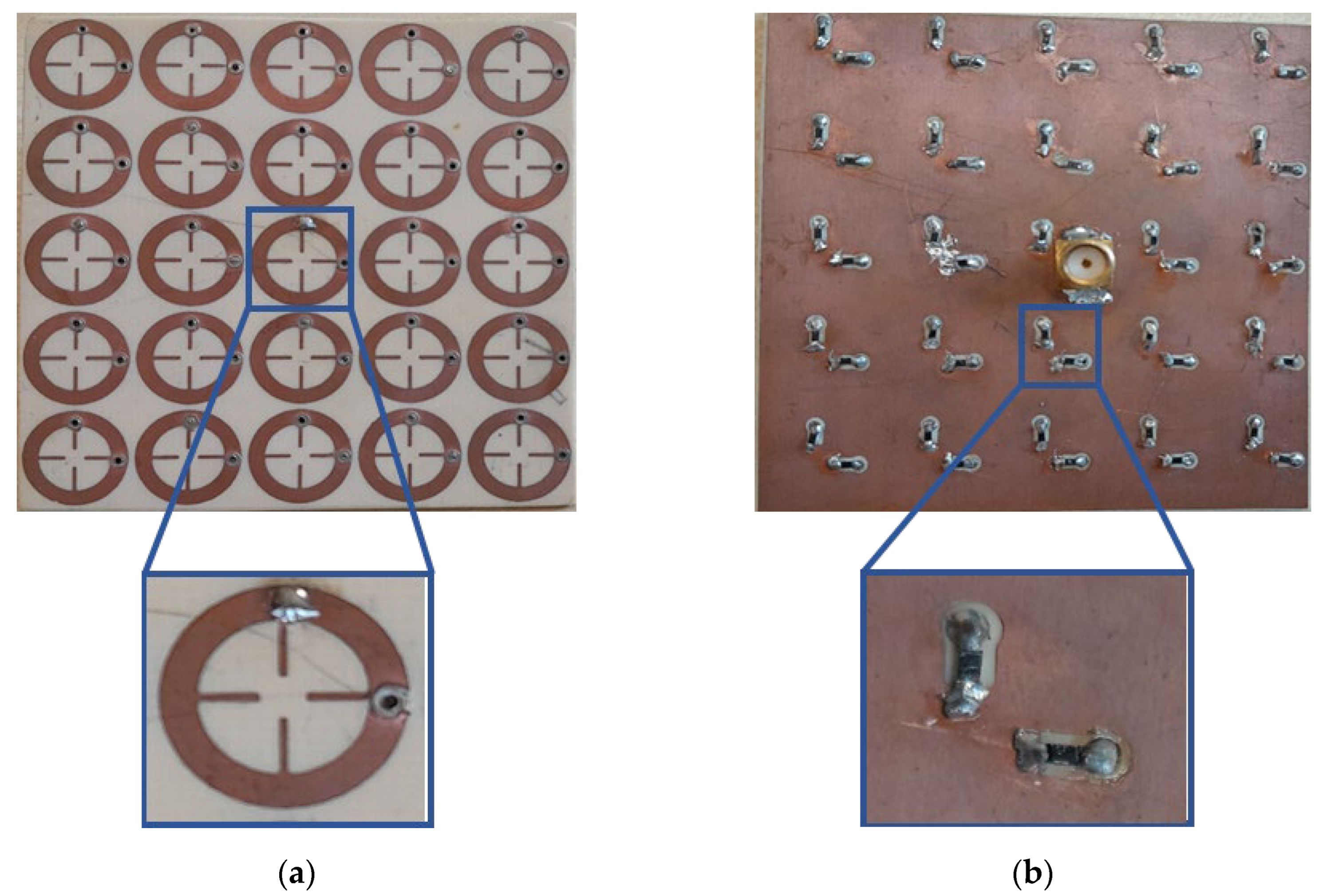
Figure 12.
Schematic of the experimental setup.
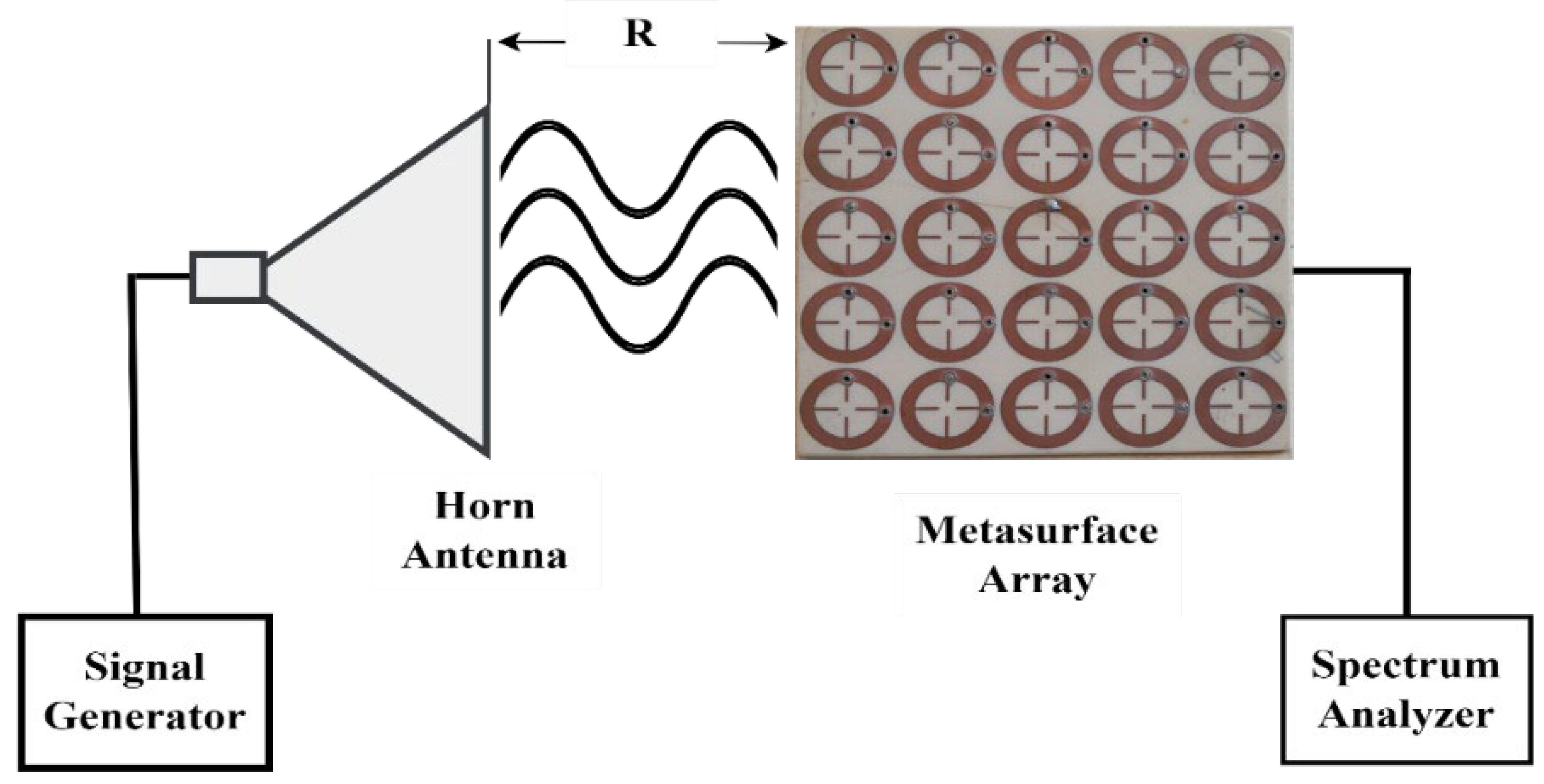
Figure 13.
Measured harvesting efficiency at various oblique incidence.
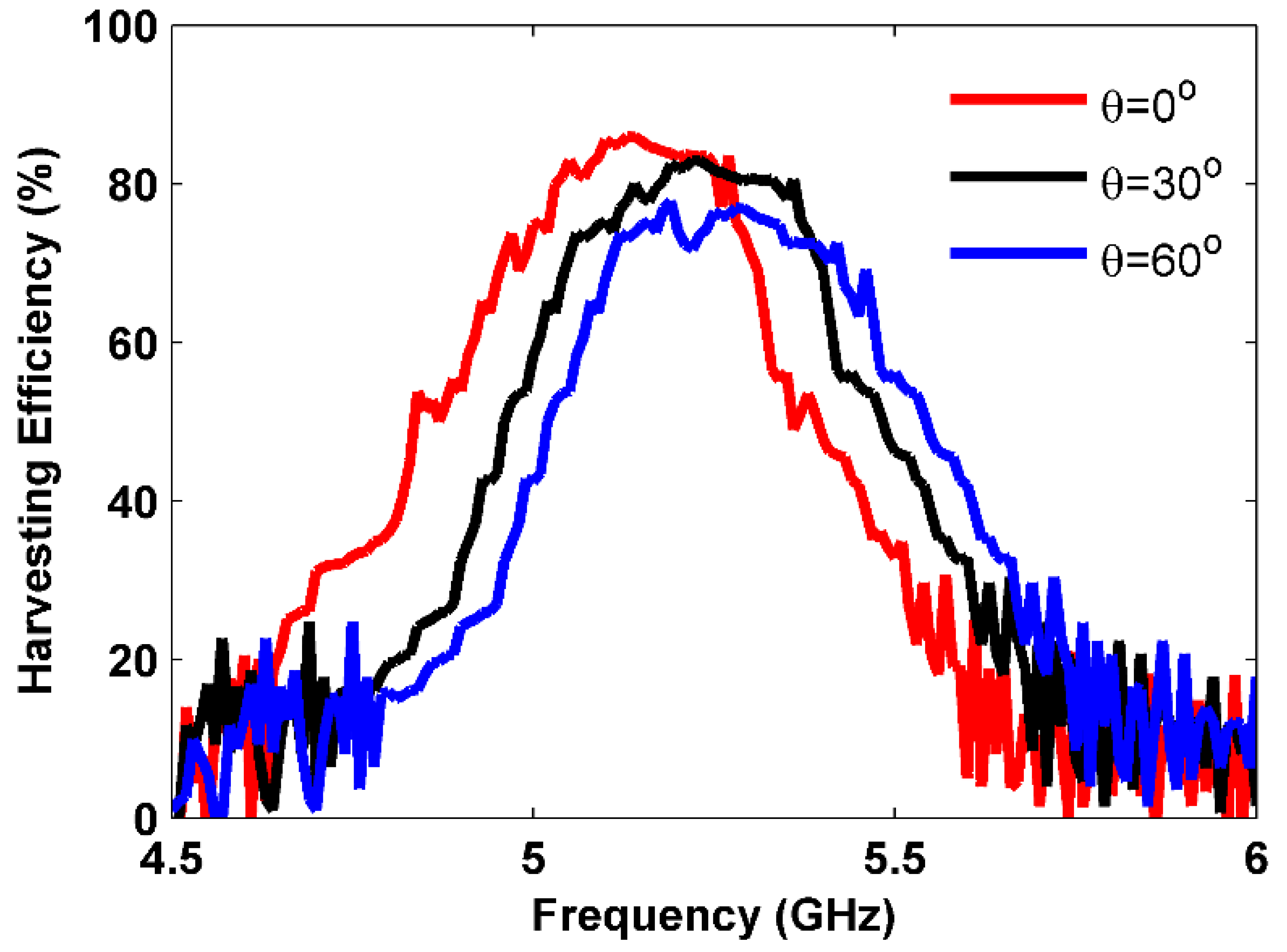

Table 1.
Optimized dimensions of the proposed MS unit cell harvester
| Parameters | Value (mm) |
|---|---|
| P | 12.7 |
| R1 | 6.1 |
| R2 | 3.9 |
| L | 7.73 |
| W | 1 |
| g | 2.6 |
Table 2.
Comparison between the proposed MS structure and similar works.
| Ref. | Size | Center Freq. (GHz) | Frequency Deviation | Incident angle |
||
|---|---|---|---|---|---|---|
| [22] | 0.17 | 5.8 | 300 MHz (5.17%) |
52% | 68% | |
| [40] | 0.29 |
5.8 | 48 MHz (0.83%) |
91% |
72% | |
| [41] | 0.22 | 7 | - | 95% |
N/A | |
| [43] | 0.54 | 5.4 | 300 MHz (5.55%) |
92% | 48% | |
| [44] | 0.65 | 9.6 | - | 95% | N/A | |
| [45] | 0.51 | 5.7 | 120 MHz (4.44%) |
81% | 30% | |
| [52] | 0.32 | 5.8 | 75 MHz (1.3%) |
88% | 62% | |
| This work | 0.21 | 5 | 19 MHz (0.32%) |
94% | 76% |
Disclaimer/Publisher’s Note: The statements, opinions and data contained in all publications are solely those of the individual author(s) and contributor(s) and not of MDPI and/or the editor(s). MDPI and/or the editor(s) disclaim responsibility for any injury to people or property resulting from any ideas, methods, instructions or products referred to in the content. |
© 2024 by the authors. Licensee MDPI, Basel, Switzerland. This article is an open access article distributed under the terms and conditions of the Creative Commons Attribution (CC BY) license (http://creativecommons.org/licenses/by/4.0/).
Copyright: This open access article is published under a Creative Commons CC BY 4.0 license, which permit the free download, distribution, and reuse, provided that the author and preprint are cited in any reuse.


