
Submitted:
12 December 2024
Posted:
13 December 2024
You are already at the latest version
Abstract
In a previous publication, the ANSYS Workbench 2024R1 student edition was used to create a finite element model of a basketball rim and backboard. This finite element model included the use of steel for the rim and its mount, a tempered glass backboard, and an aluminum frame behind the backboard. After a mesh was created, fixed support boundary conditions were applied to the four corners of the aluminum frame. Using the Workbench Modal Analysis System, finite element mode shapes and frequencies were compared to the empirical modal analysis previously done at the United States Military Academy at West Point, New York. After a mesh refinement, five mode shapes and frequencies had a cross-correlation of 98.09% between the theoretical finite element analysis and previously published empirical modal analysis, specifically where the rim was vi-brating in the vertical direction, which was the direction that the accelerometer was aligned for the empirical modal analysis. This vertical direction was also the direction of the impulse applied by the Energy Rebound Testing Device (ERTD), which was the focus of this study.
This paper is a follow-on to the original finite element analysis, where the Energy Rebound Testing Device was also modeled, this time using the ANSYS Workbench 2024R2 student edition The first modal model was of the ERTD in isolation in the Workbench Modal Analysis system, and the natural frequency modeled via finite element analysis, 12.776 Hz, compared favorably with the empirical modal analysis value of 12.72 Hz. The second modal model, also in the Workbench Modal Analysis system, was of the ERTD rotatably-attached to a basketball rim and backboard. This second model was then imported into the Transient Structural Analysis system and then used to confirm the hypothesis that the ERTD adopted by the NCAA for the sport of Basketball was indeed responsive to changes in rim and backboard stiffness via changes in the respective Young’s Moduli.
Keywords:
Dynamics
; Kinetic Energy
; Finite Element Analysis
; Basketball Rim and Backboard
; Energy Rebound Testing Device
; Fair-Court Official Basketball Equipment Testing System
1. Introduction
This study was inspired by the impact studies of Tanaka, et-al., [1], Matsuda, et-al., [2], Takizawa, et-al., [3], and Yin, et-al., [4]. Tanaka used finite element analysis to model carbon-fibre reinforced golf clubs, specifically to study the effect torsional shaft stiffness had on golf ball impact. Matsuda used finite element analysis simulated the deformation of the string bed in a tennis racket due to a tennis ball. Via nonlinear finite element analysis, Takizawa concluded that the nonlinear mechanical properties of the polymer strings of the badminton racket made the calculated sweet-spot of the string planes smaller. Yin employed the finite element method to evaluate the von Mises stress distribution in the string-bed of a badminton racket upon the impact of the hemispherically-shaped nose of a shuttlecock. Nonuniform string tension, nonlinear friction between strings, and different impact locations were included in Yin’s study.
Javorksi, et-al., [5] first characterized the dynamic behavior of a ceiling-mounted basketball goal using an impact hammer and a fixed-location accelerometer, and then compared that empirical analysis to a theoretical finite element analysis. Empirical vibration measurements were taken at fourteen nodes, ten of which were on the frame supporting the basketball rim and backboard. Only four nodes were measured on the backboard, at the corners of the backboard, and none on the rim itself. Overall, 36 frequency response functions were measured, and this study concentrated mostly on structural vibrations between 2 and 10 Hz. Thus, this important study was focused more on the structural support of the backboard and rim rather than the elastic vibrations of the backboard and rim themselves.
2. Empirical Modal Parameters of one Energy Rebound Testing Device
Table 1 lists key empirical measured modal parameters of one Energy Rebound Testing Device (ERTD) [13,14], which is also known as the Fair-Court® Official Basketball Equipment Testing System. All measurements were taken at the United States Military Academy at West Point. In Table 1, the damped frequency ωd and damping ratio ζ were measured using the same Brüel & Kjær (B&K) 2034 signal analyzer, B&K 4393 accelerometer [15], B&K 8202 impact hammer, B&K 8200 force transducer, B&K 2644 line-driver charge-amplifiers, and Structural Measurements System (SMS) software as used on the basketball rim and backboard, Winarski, et-al., [16]. The B&K 8202 impact hammer (excitation) was used to individually gently tap the drop-mass, while the B&K 4393 accelerometer was affixed to it with beeswax. The ERTD was vertical and supported from its base which was in contact with a concrete floor, rather than being hung from a basketball rim. From this, the damped frequency ωd = 12.59Hz and damping ratio ζ = 14.61% were measured, as listed in Table 1. Using ωd / √(1−ζ2), the natural frequency of ωn = 12.72Hz was calculated. The natural frequency allowed us to estimate the spring rate of the ERTD as K_estimate = ωn2 × M_drop = 4730 N/m.
The drop-mass had a value of 0.74kg (26 ounces), which was only slightly higher than the 20-22 ounce weight of a men’s NCAA basketball [17]. The 0.74kg drop-mass and the natural frequency of 12.72Hz converted to radians/second gave an estimated spring rate of the helical compression-spring of 4730N/m. It was against this compression-spring that the 0.74kg drop-mass was dropped from a height of h=30 inches (0.762m). This gave an impact velocity of 3.866 m/s, calculated from V_drop = √(2×g×h), when the drop-mass first engaged the helical compression-spring, which became the initial condition for our modeling in the ANSYS Workbench Explicit Dynamics system.
The goal of our finite element modeling was to evaluate the normalized kinetic energy transfer from the drop-mass to the basketball rim and backboard as [(KE_drop − KE_rebound)/KE_drop]. Since the drop-mass is a common term, this normalized kinetic energy transfer simplified to [1 – (Vrebound/Vdrop)2].
A preliminary estimate of the maximum deflection ΔZ of the helical compression-spring was made by assuming that no energy was transferred to the basketball rim and backboard. This gave the kinetic energy of the drop-mass upon touching the spring equaling the potential energy stored in the spring, ½M_drop×V_drop2 = ½K_estimate×ΔZ2. This estimated a maximum possible deflection of the compression spring ΔZ of approximately 48mm. The next step was to apply the ANSYS Workbench 2024R2 modal analysis system.
3. ANSYS Workbench 2024R2: ERTD in Isolation
We first launched ANSYS Workbench 2024R2 [18], then double-clicked on MODAL under Analysis Systems in Workbench. This caused the MODAL cell to be displayed in the project schematic window. We then clicked on Engineering Data to define the spring wire properties of ASTM A 228 music wire [19], most importantly the shear modulus G = 80GPA. We then right-clicked on Geometry within MODAL and selected DesignModeler Geometry from the menu. We did use English dimensional units because the Gared [20] basketball rim, mount, backboard, and ERTD are specified in inches in the United States.
The isolation modeling of the ERTD began with declaring the long cylindrical rod and its cylindrical base, as shown in blue in Figure 1. The drop-mass was modeled as a toroid from the create-primitives section. It was desired to use the spring connection in ANSYS, and to locate the ends of each spring, auxiliary locator-cones were used from the create-primitives section. The inspiration for these auxiliary locator-cones came from [21], where auxiliary locator-flats were used to locate spring ends. Since four springs were desired, equally spaced along the horizontal X and Y axes, eight cones were employed. The overall mass of the drop-mass and its four cones was 0.74kg, matching the drop-mass used in the ERTD at the U.S. Military Academy at West Point.
After exiting Geometry, Model>Connections was entered, in order to declare four spring elements and one joint. By highlighting a pair of upper and lower cones, then declaring a body-body spring connection, all four springs were created. The material assigned to each spring was music wire, and the spring rate assigned to each of the four springs was 1182.5N/m (4730N/m, from Table 1, divided by four). Finally, the drop-mass and the drop-rod were connected with a body-body cylindrical joint. In ANSYS, a joint is indicated by a ball-in-socket icon. This cylindrical joint constrained the drop-mass to translation and rotational motion along the length of the rod itself, which was exactly how the drop-mass was constrained in an actual ERTD.
Setup>Environment was then entered, to assign a fixed boundary condition constrained the base and hence the rod. The only motion desired was that of the drop-mass.
This model was then meshed and solved for the first mode of vibration. Table 2 shows that the natural frequency of the undamped spring-mass system shown in Figure 1 was 12.776Hz, which compared favorably with the empirically measured natural frequency of 12.72Hz (Table 1). At this point, a damping value of 4.3Ns/m (17.2Ns/m from Table 1, divided by four) was assigned to each of the four springs. Via Model>Modal>Analysis-settings, the damping solver was then engaged, and the damped natural frequency of the spring-mass system shown in Figure 1 was 12.639Hz, which compared favorably with the empirically measured damped natural frequency of 12.59Hz (Table 1). Table 1 also lists the frequency difference between ωn - ωd which was 12.72-12.59=0.13Hz for the empirical modal analysis and 12.776-12.639=0.137Hz. Thus, the change in frequency between undamped and damped only varied by 0.137-0.13=0.007Hz between the theoretical finite element analyses and the empirical modal analyses.
With this validation confirming our approach, we proceeded to merge the ERTD with the basketball rim and backboard previously modeled in [22].
4. ANSYS Workbench 2024R2: Merging ERTD and Basketball Rim and Backboard
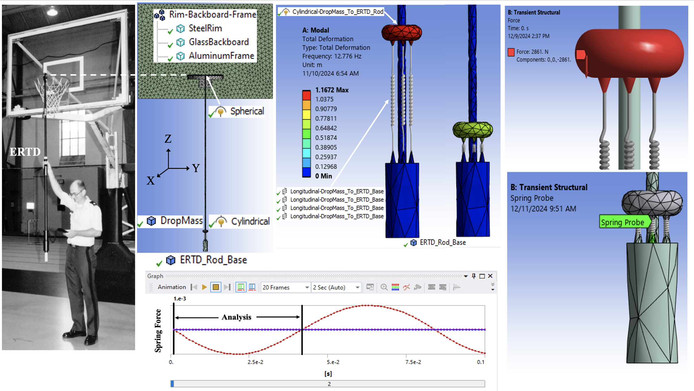
Figure 2 compares an actual Energy Rebound Testing Device hanging from the outermost portion of a basketball rim with the corresponding Finite Element model as done with ANSYS. The finite element model of the basketball rim, backboard, and frame were the same previously used in [22]. The detail shown in Figure 1 was added to Figure 2 by extending the drop-rod upward, to the basketball rim, within Geometry.
Within Model>Connections, the drop-rod and rim were connected with a body-body spherical joint. This spherical joint permitted rotational motion in all three directions, but blocked any translation motion, which was exactly how the rod was constrained by connecting an actual ERTD to an actual basketball rim in Figure 2.
The fixed boundary condition which had been applied to the base of the ERTD when studied in isolation was not used in this merged study. Thus, the ERTD was able to pivot about the spherical joint which connected it with the basketball rim.
In Figure 3, steps 30-44 were used to create the geometry of the ERTD. Steps 1-29 were previously used to create the geometry of the rim-backboard-frame in [22]. The geometric construction began with creating (denoted by a saw icon) a circle of 0.6” (15.24mm) diameter in the offset horizontal XY plane used to create the wing brace, step 14 [22]. The 0.6” diameter was chosen because the slightly larger diameter of the toroid compising the steel rim was 0.625”. Then this circle was extruded upwards to the rim in step 31 and then downwards in step 32.
An additional offset XY plane was created in step 33, for the creation of a circle in step 34 defining the cylindrical cross-section of the base. This circle was extruded downwards to complete the base in step 35. Then four pairs of auxiliary locator-cones were created from the create-primitives section, steps 36-43, before creating the drop-mass from the create-primitives section, step 40.
Table 3 shows that the rim and its mount, as well the backboard and its frame, were modeled with 6315 tetrahedron-10 elements, 120 pyramid-13 elements, 4 wedge-15 and 120 hexahedral-20 elements. The ERTD rod and base were modeled with 1854 tetrahedron-10 elements and the drop-mass was modeled with 348 6315 tetrahedron-10 elements. Table 3 was dominated by tetrahedron elements, which was the primary element used in [12]. Four fixed support boundary conditions were then individually applied, one to each of the four outer corner vertices of the aluminum frame behind the backboard, as described in [22].
After creating four springs in Model, one spring per pair of auxiliary locator-cones, each of the four springs was declared to have a spring rate of 1182.5N/m. The damping of 4.3Ns/m in each spring was deemed so small that the use of the damping solver was considered an unnecessary complication for this complicated structure. Then the ERTD rod and basketball rim were connected with a body-body spherical joint and the ERTD rod and drop-mass were connected with a body-body cylindrical joint.
Figure 4 shows five modes of vibration calculated by ANSYS. From left-to-right, the first mode at 12.133 was dominated by the motion of the drop-mass, and the drop-mass and rim vibrated in phase. The second mode at 21.855Hz showed the rim 180° out of phase with the drop-mass. Modes 3 and 4, 36.553Hz and 48.503Hz, were interesting because the bowing of the backboard in Mode 4 was 180° out of phase from the bowing of the backboard in Mode 3. Finally, mode 5 at 78.66Hz showed the elastic flexure of the steel rim itself. At this point we were ready to apply the modal superposition method to analyze the kinetic energy transfer from the drop-mass to the basketball rim, backboard, frame, and drop-rod itself.
5. ANSYS Workbench 2024R2: Transient Dynamics System
The Energy Rebound Testing Device (ERTD) implemented on a basketball rim, backboard, and frame was then modeled with the modal superposition method of solution [23]. We made our system linear by terminating each simulation as the drop-mass was about to detach from the compression springs, Figure 1. This linearization was sufficient for our purposes, as the departure velocity of the drop-mass was a key object of each simulation.
To use the modal superposition method of solution, we dropped transient structural on the solution cell of the modal analysis in Workbench. This gave the connectivity shown in Figure 5.
In Figure 5, there are three data sharing links, between the engineering data, geometry, and model cells, respectively, as indicated by a straight line and a square, [24]. There is one data transfer link, between the solution cell in modal and the setup cell in transient structural, as indicated by a curved line and a circle. In transient structural, the pair of green arrows in the setup cell indicated that a refresh was required. This refresh was accomplished by right-clicking on the setup cell and clicking on update within the edit menu.
Once the setup cell in transient solution was refreshed in Figure 5, the upper portion of Figure 6 showed that the setup, solution, and results cells of modal needed updating. The lower portion of Figure 6, show that once setup, solution, and results were updated in modal, question marks in the setup, solution, and results cells in transient structural indicated that these were unfulfilled and needed attention.
The desired initial condition of the basketball-rim-backboard-frame and the attached ERTD, as shown in Figure 2 and Figure 3, was -3.866m/s for the ERTD drop-mass. The direction of this initial velocity was downward, along the vertical “Z” direction. Figure 7 shows how this initial condition was obtained in two steps via the impulse-momentum equation. Assuming that the initial force was constant and applied for the initial time step of 0.001s, gave F = (0.74kg × -3.866m/s)/0.001s = -2861N for the first step. The second step was to deactivate this force after 0.001 seconds, in setup, to allow the free motion of the drop-mass and drop-rod, as well as the basketball rim, backboard, and frame. After these updates to the analysis settings, the solution and results were successfully generated.
6. Sensitivity Study: Effect of Rim and Backboard Stiffnesses on Energy Transfer
In Table 4 and Table 5, the drop velocity Vdrop, the rebound velocity of the drop-mass Vrebound, and the energy transferred from the drop-mass are shown. Via the spring probe, Figure 8, analyses began at 1ms and terminated when the drop-mass was about to disengage from the compression spring.
The Vdrop and Vrebound velocities were calculated by the use of the spring probe, which gave the spring force. By dividing the spring force by the spring rate, the displacement of the drop-mass relative to the drop-rod was calculated. The displacement versus time was used to numerically calculate the velocity of drop-mass relative to the drop-rod. The ERTD also calculated the velocity of drop-mass relative to the drop-rod.
Table 4 documented the energy transfer for changes in the Young’s modulus of the glass backboard, and Table 5 documented the energy transfer for changes in the Young’s modulus of the steel rim. In both tables, as the respective Young’s modulus was reduced, the energy transferred increased, which confirmed our hypothesis.
7. Conclusions
This paper gives a process of creating a geometry, mesh, and boundary conditions for a basketball rim, mount, backboard, and border frame as well as the Energy Rebound Testing device, for the purpose of theoretical finite element analysis. The Energy Rebound Testing Device (ERTD) implemented on a basketball rim, backboard, and frame was first modeled in Modal then further modeled with the modal superposition method of solution in Transient Structural.
There are many possible designs of rims, backboards, and frames which meet NCAA standards, so this study is not comprehensive across the sport of basketball. However, our efforts of finite element analysis did confirm our hypothesis that as the respective Young’s modulii of the glass backboard and steel rim were reduced, the energy transferred from the drop-mass of the Energy Rebound Testing Device increased.
Author Contributions
Conceptualization, K.P.N.; methodology, D.W.; validation, K.P.N., D.W. and T.W.; formal analysis, D.W. and T.W.; investigation, D.W. and T.W.; writing—original draft preparation, D.W.; writing—review and editing, K.P.N., D.W. and T.W.; visualization, K.P.N. and D.W.; supervision, K.P.N.; project administration, K.P.N. All authors have read and agreed to the published version of the manuscript.
Funding
This research received no external funding.
Acknowledgments
Ms. Donna Robinson Winarski is acknowledged for her support of this research, both at the United States Military Academy at West Point, New York, and at Tucson, Arizona. Her assistance with initial editing as well as data taking was very much appreciated.
Conflicts of Interest
The authors declare no conflict of interest.
References
- Tanaka, K.; Sekizawa, K. Construction of a finite element model of golf clubs and influence of shaft stiffness on its dynamic behavior. Proceedings 2018, 2, 247. [Google Scholar] [CrossRef]
- Matsuda, A.; Nakui, M.; Hashiguchi, T. Simulation of Mechanical Characteristics of Tennis Racket String Bed Considering String Pattern. Proceedings 2018, 2, 264. [Google Scholar] [CrossRef]
- Takizawa, M.; Matsuda, A.; Hashiguchi, T. A Study on the Mechanical Characteristics of String Planes of Badminton Racquets by Nonlinear Finite Element Analysis. Proceedings 2020, 49, 42. [Google Scholar] [CrossRef]
- Yin, S.-R.; Chang, H.-C.; Cheng, K.B. Impact Characteristics of a Badminton Racket with Realistic Finite Element Modeling. Proceedings 2020, 49, 106. [Google Scholar] [CrossRef]
- Javorski, M.; Čermelj, P.; Boltežar, M. Characterization of the Dynamic Behaviour of a Basketball Goal Mounted on a Ceiling. J. Mech. Eng./Stroj. Vestn. 2010, 56, https://www.sv-jme.eu/–ns_articles_pdf=/ns_articles/files/ojs3/1513/. [Google Scholar]
- Nkounhawa, Pascal Kuate, et al. "Analysis of the Behavior of a Square Plate in Free Vibration by FEM in Ansys." World Journal of Mechanics 10.02 (2020): 11-25.
- Guguloth; Naik, G.; Singh, B.N.; Ranjan, V. Guguloth; Naik, G.; Singh, B.N.; Ranjan, V. Free vibration analysis of simply supported rectangular plates. Vibroengineering Procedia 2019, 29, 270–273. [Google Scholar] [CrossRef]
- Irvine, T.; The Natural Frequency of a Rectangular Plate Point-Supported at Each Corner, Revision C. 1 August 2011. Available online: http://www.vibrationdata.com/tutorials2/plate_point_corner.pdf (accessed on 25 July 2023).
- Dumond, P.; Monette, D.; Alladkani, F.; Akl, J.; Chikhaoui, I. Simplified setup for the vibration study of plates with simply- supported boundary conditions. Methods X 2019, 6, 2106–2117. [Google Scholar] [CrossRef] [PubMed]
- Anđelić, N., Čanađija, M.; Car, Z.. "Determination of Natural Vibrations of Simply Supported Single Layer Graphene Sheet using Non-Local Kirchhoff Plate Theory." IN-TECH 2017 International Conference on Innovative Technologies. 2017, p.5.
- Geveci, B.; Walker, J.D.A. Nonlinear resonance of rectangular plates. Proceedings of the Royal Society of London. Series A: Mathematical, Physical and Engineering Sciences 2001, 457, 1215–1240. [Google Scholar]
- Covill, D.; Drouet, J.-M. On the Effects of Tube Butting on the Structural Performance of Steel Bicycle Frames. Proceedings 2018, 2, 216. [Google Scholar] [CrossRef]
- Assembly, Operation & Maintenance Manual: Fair-Court® Official Basketball Equipment Testing System, No. ERTD2003NCAA. Copyright 2003 by the Porter Athletic Equipment Company. Available online: https://cdn.arenacommerce.com/basketballproductsinternational/Porter%20Fair-Court%20Rim%20Testing%20System_090109030803-fair-court-instructions.pdf.
- Abbott, W.B.; Karl, C.D. Portable Basketball Rim Testing Device. US Patent 5214954, 1 June 1993. [Google Scholar]
- Product Data: Piezoelectric Charge Accelerometer Types 4393 and 4393-V. Copyright 2018-08 by Brüel & Kjaer. Downloaded from: https://www.bksv.com/media/doc/bp2043.pdf.
- Winarski, D.; Nygren, K.P.; Winarski, T.. 2023. "Modes of Vibration in Basketball Rims and Backboards and the Energy Rebound Testing Device" Vibration 6, no. 4: 726-742. Available online: https://www.mdpi.com/2571-631X/6/4/45. [CrossRef]
- 2024-2025 NCAA Men’s Basketball Rules Handbook, August 2024. Manuscript Prepared By: Jeff O’Malley, Secretary-Rules Editor, NCAA Men’s Basketball Rules Committee. Edited By: Andy Supergan, Associate Director of Playing Rules and Officiating. https://www.ncaapublications.com/productdownloads/BK25.pdf (accessed on 13 November 2024).
- ANSYS 2024 R2 Student Edition: Available online:. Available online: https://www.ansys.com/academic/students/ansys-student (accessed on 30 June 2024).
- Music Wire – ASTM A 228 – Spring Wire Properties. Downloaded from https://optimumspring.com/technical_resources/materials/carbon_steels/music_wire_228_spring_wire.aspx (accessed 1 July 2024).
- Model 3500 Positive Lock Breakaway Goal Updated 21 January 2010 Gared Holdings, L.L.C. Available online: https://www. garedsports.com/sites/default/files/import/files/3500I%2520spec%2520-revA.pdf (accessed on 7 September 2023).
- Choudhari, C.J. “Spring Support/Connection,” Endurance Engineering Solutions, ANSYS Tutorial 28. https://www.youtube.com/watch?v=TiTjBspNu7o. (accessed on 11 November 2024).
- Winarski, D.; Nygren, K.P.; Winarski, T. Finite Element Analysis versus Empirical Modal Analysis of a Basketball Rim and Backboard. Vibration 2024, 7, 582–594, Available online at https://www.mdpi.com/2571-631X/7/2/30. [Google Scholar] [CrossRef]
- Mode Superposition Transient Analysis Using Ansys Mechanical – Lesson 1. (accessed on 25 November 2024). https://www.youtube.com/watch?v=3fHu5fMHNeU.
- Tickoo, S. ANSYS Workbench 2023 R2: A Tutorial Approach; CADCIM Technologies: Schererville, IN, USA, 2023; pp. 2–28, 9-59.
Figure 1.
Natural frequency of 12.776 Hz for Drop-Mass: ERTD isolated and undamped.
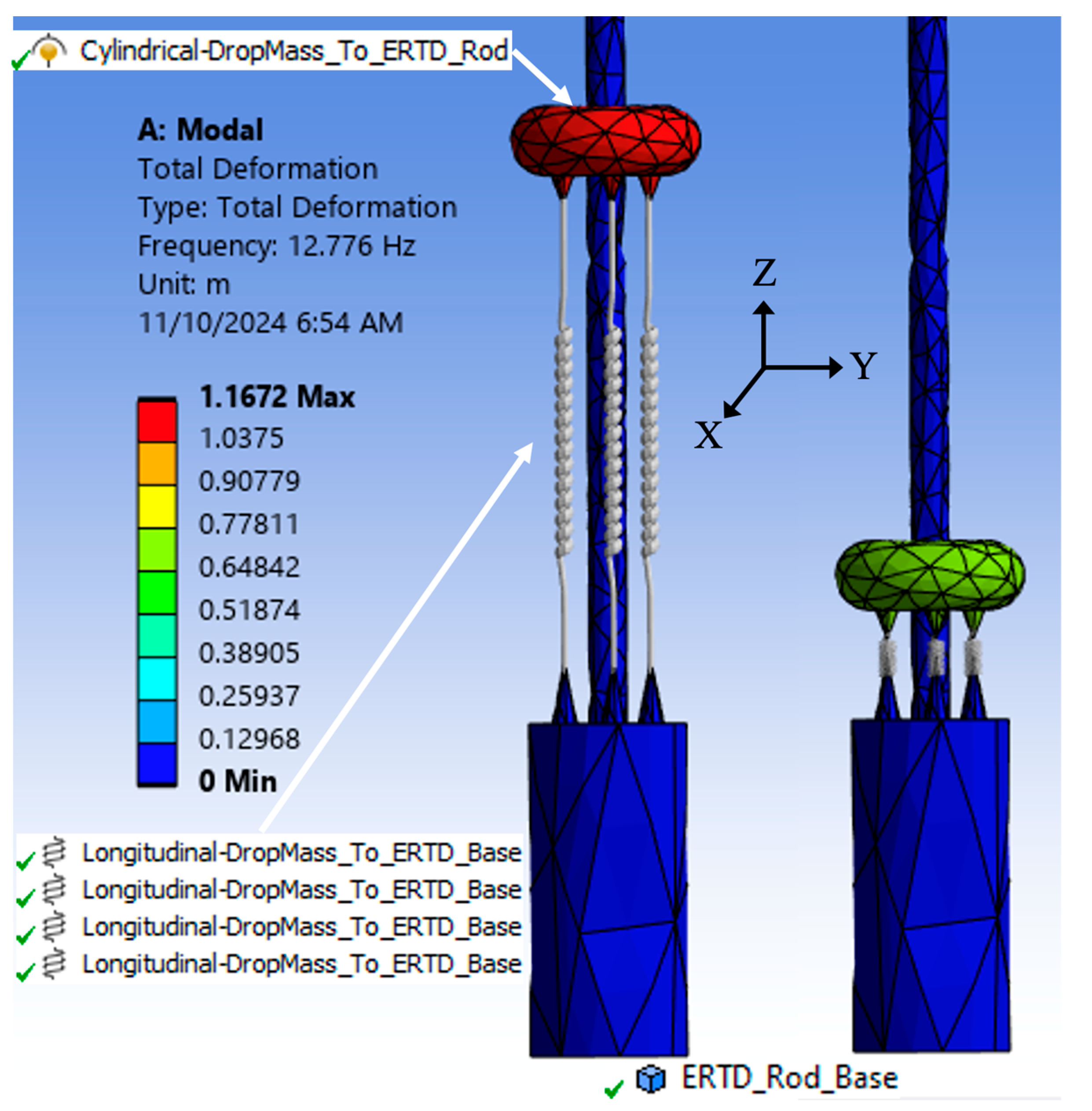
Figure 2.
Actual versus Finite Element modeled ERTD.
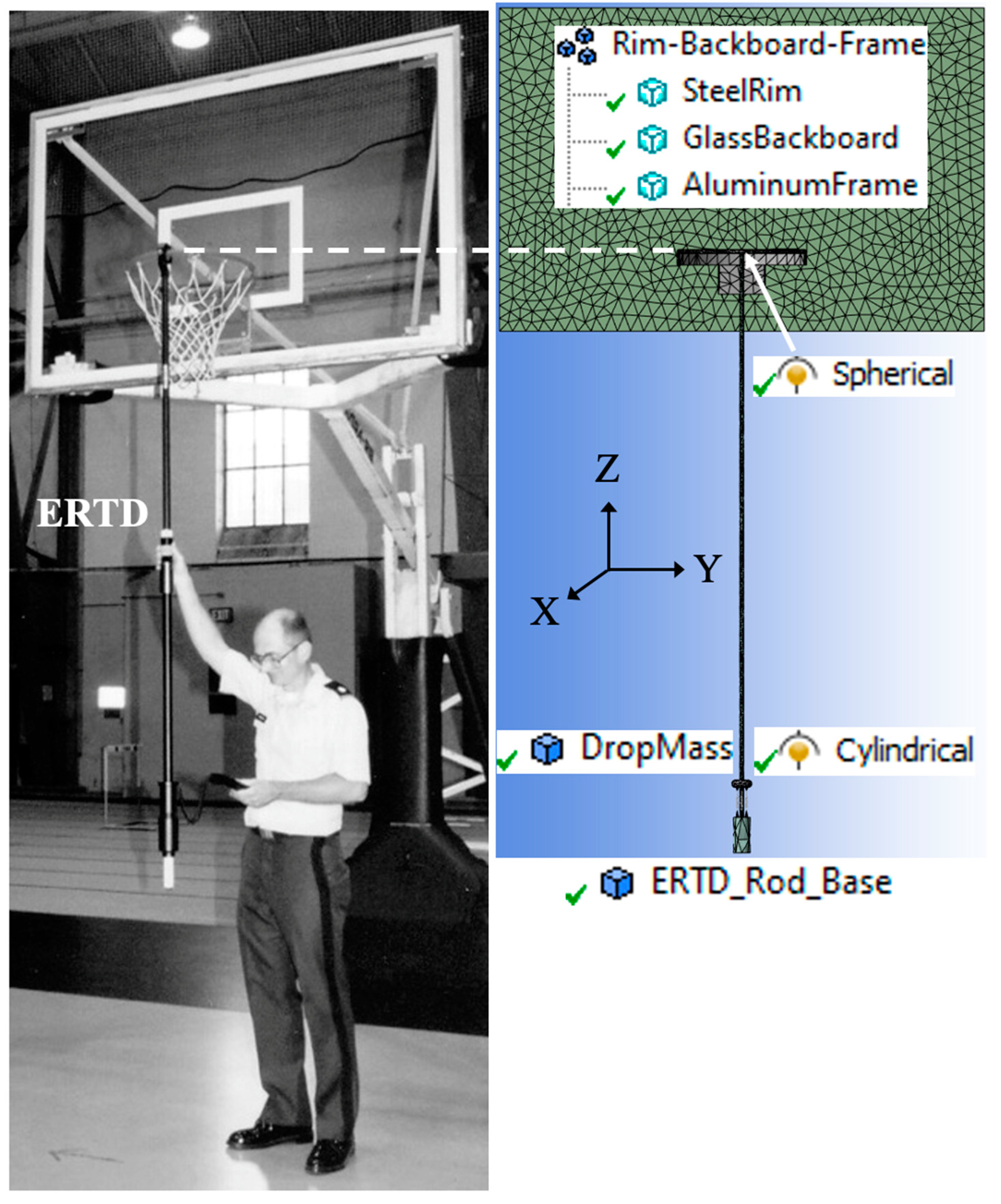
Figure 3.
Steps 30-44 used to create the Energy Rebound Testing Device.
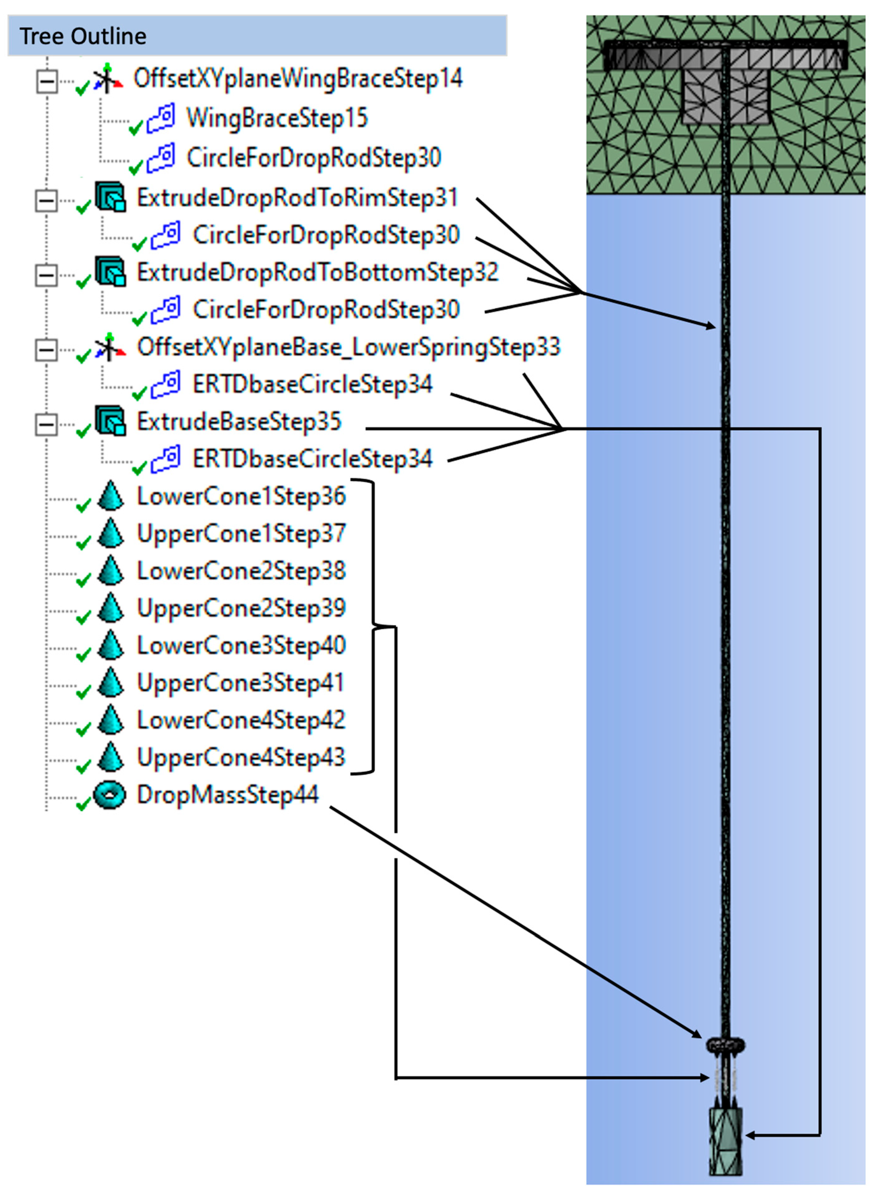
Figure 4.
Five modes: 12.133Hz, 21.855Hz, 36.553Hz, 48.503Hz, and 78.66Hz respectively.
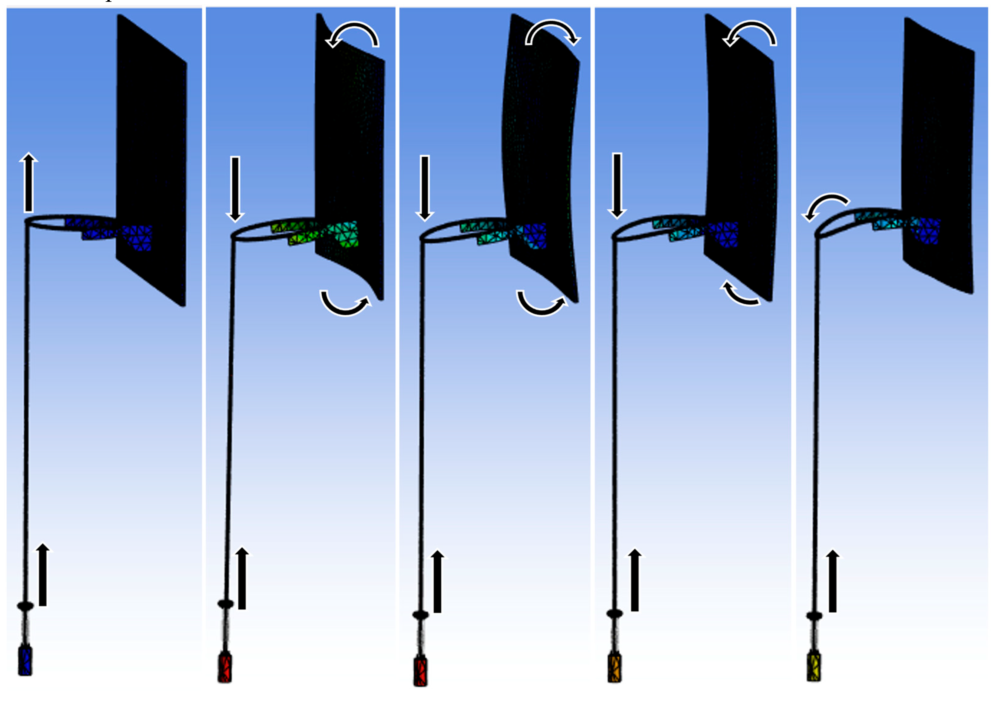
Figure 5.
Dropping transient structural on the solution cell of modal, refreshing setup.
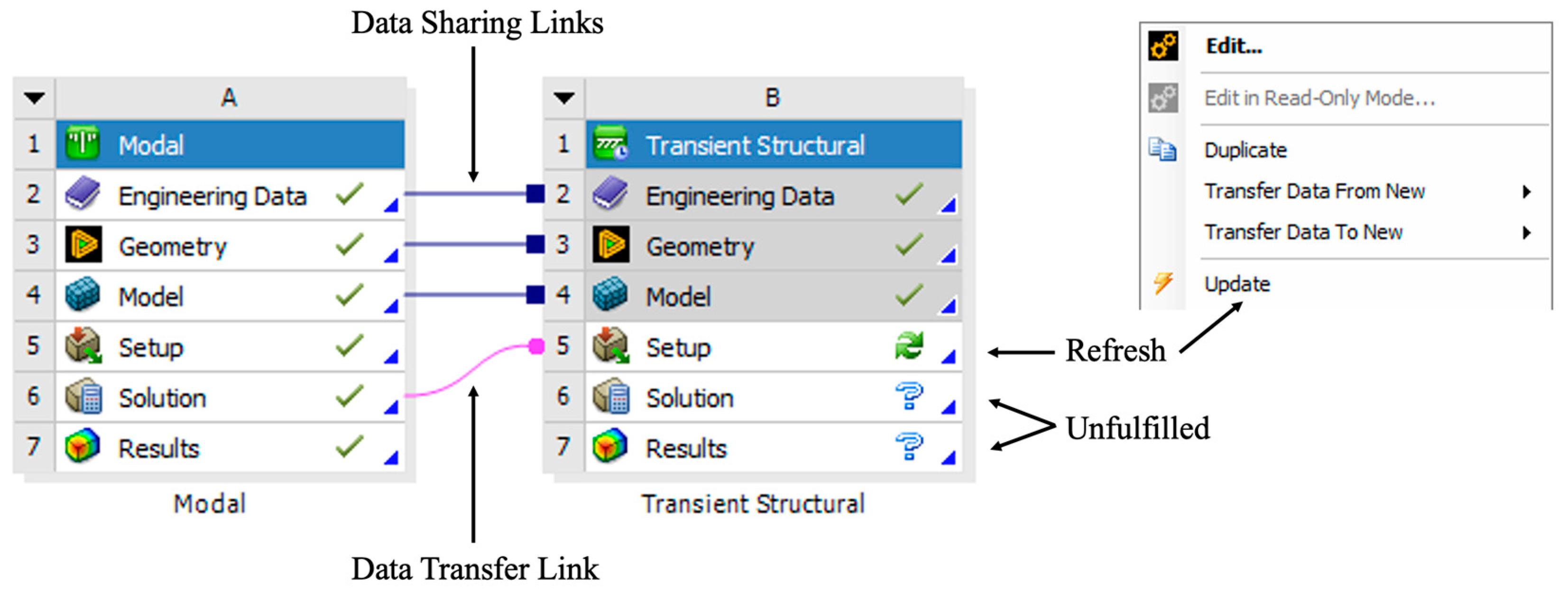
Figure 6.
Updating setup, solution, and results in Modal.
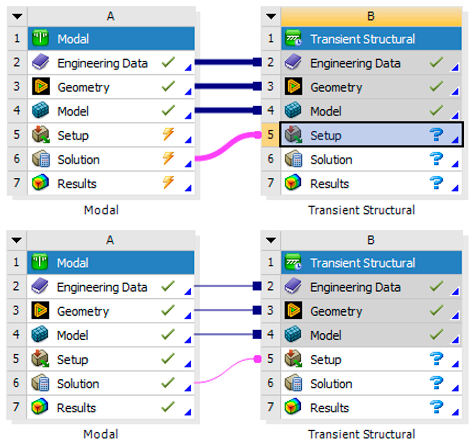
Figure 7.
Application of impulse-momentum to achieve initial velocity of Drop-Mass: -3.866m/s.
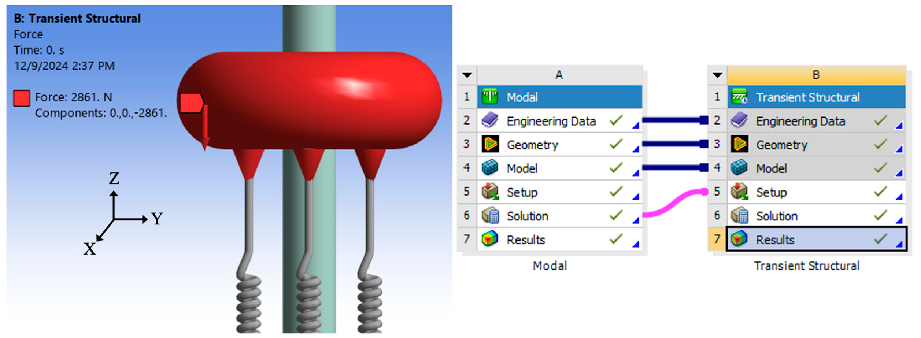
Figure 8.
The spring probe indicated when to calculate Vdrop and Vrebound.
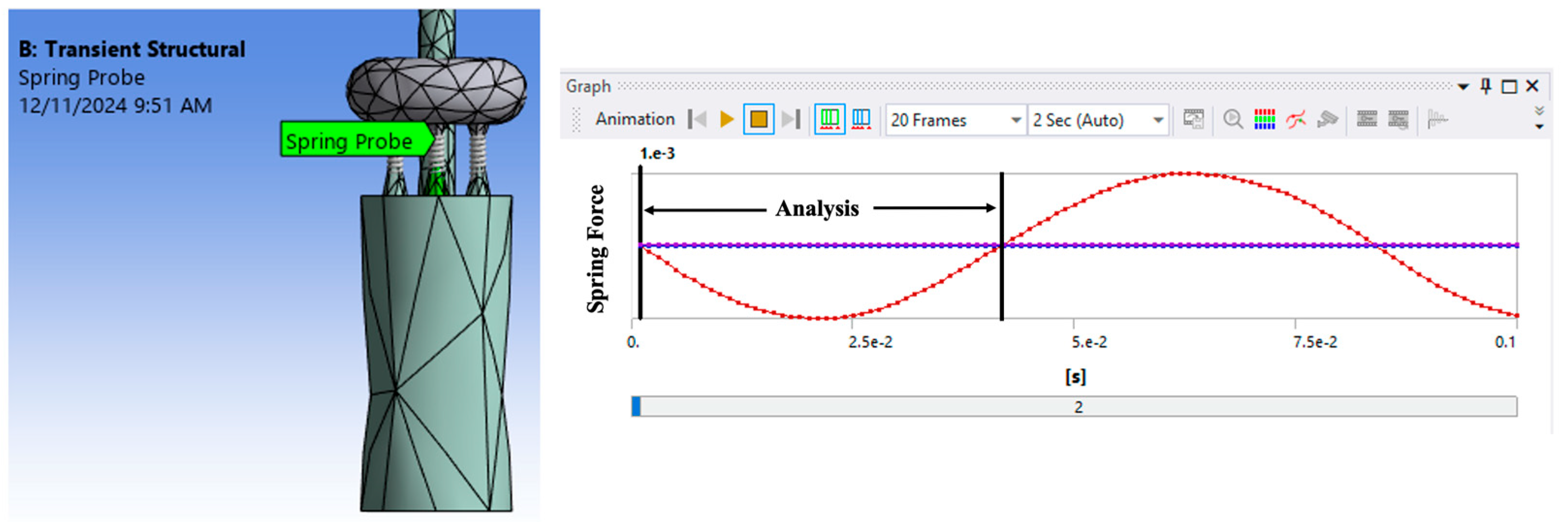

Table 1.
Key modal parameters of one Energy Rebound Testing Device.
| Parameter | Description | Value | How Measured |
|---|---|---|---|
| ωd | Damped Frequency | 12.59 Hz | B&K 2034 |
| ζ | Damping Ratio | 14.61% | SMS Software |
| ωn | Natural Frequency | 12.72 Hz | ωd / √(1−ζ2) |
| M_drop | Drop-Mass | 0.74 kg | Direct Measurement |
| K_estimate | Compression-Spring | 4730 N/m | ωn2 × M_drop |
| Cc | Critical Damping | 118 Ns/m | 2 √(k×M_drop) |
| C | Damping | 17.2 Ns/m | ζ×Cc |
| M_rod | Mass of Support Rod | 2.26 kg | Direct Measurement |
| Calibration | Average Calibration | 12.8% | Direct Measurement |
Table 2.
Validation: Empirical vs Finite Element Natural and Damped Natural Frequencies.
| Parameter | Description | Empirical | Finite Element |
|---|---|---|---|
| ωn | Natural Frequency | 12.72 Hz | 12.776 Hz |
| ωdωn - ωd | Damped Frequency Frequency Difference |
12.59 Hz 0.13 Hz |
12.639 Hz 0.137 Hz |
Table 3.
Mesh elements and nodes, and boundary conditions.
| Parameter | Rim, Backboard, Frame | ERTD Rod and Base | Drop-Mass | Total |
|---|---|---|---|---|
| Solid (3-D) Elements | 6559 | 1854 | 348 | 8761 |
| Nodes | 14252 | 4243 | 712 | 19207 |
| Corner-Nodes | 2606 | 809 | 127 | 3542 |
| Mid-Nodes | 11646 | 3434 | 585 | 15665 |
| Tetrahedron-10 | 6315 | 1854 | 348 | 8517 |
| Pyramid-13 | 120 | 120 | ||
| Wedge-15 | 4 | 4 | ||
| Hexahedral-20 | 120 | 120 | ||
| Boundary Conditions | 4 | 4 |
Table 4.
Sensitivity of Young’s Modulus of Glass Backboard on Energy Transfer.
| E Glass | Vdrop | Vrebound | 1-(Vrebound/Vdrop)2 |
|---|---|---|---|
| -20% | -3.8252m/s | 3.2159m/s | 29.32% |
| 69 GPa +20% |
-3.8256m/s -3.8258m/s |
3.2224m/s 3.2687m/s |
29.04% 27.00% |
Table 5.
Sensitivity of Young’s Modulus of Steel Rim on Energy Transfer.
| E Rim | Vdrop | Vrebound | 1-(Vrebound/Vdrop)2 |
| -20% | -3.8253m/s | 3.2206m/s | 29.11% |
| 200 GPa +20% |
-3.8256m/s -3.8260m/s |
3.2224m/s 3.2555m/s |
29.05% 27.60% |
Disclaimer/Publisher’s Note: The statements, opinions and data contained in all publications are solely those of the individual author(s) and contributor(s) and not of MDPI and/or the editor(s). MDPI and/or the editor(s) disclaim responsibility for any injury to people or property resulting from any ideas, methods, instructions or products referred to in the content. |
© 2024 by the authors. Licensee MDPI, Basel, Switzerland. This article is an open access article distributed under the terms and conditions of the Creative Commons Attribution (CC BY) license (http://creativecommons.org/licenses/by/4.0/).
Copyright: This open access article is published under a Creative Commons CC BY 4.0 license, which permit the free download, distribution, and reuse, provided that the author and preprint are cited in any reuse.


