Submitted:
12 December 2024
Posted:
14 December 2024
You are already at the latest version
Abstract
Today, the electric power industry occupies a key position in the country's economy. In the age of digitalization, it is impossible to imagine any working system without electricity. Due to the growing dependence of all spheres of human activity on electricity, the requirements for quality and reliability of electrical energy are also growing. Today, the problem associated with ground faults (GF) in 6-35 kV distribution electrical networks remains unresolved. In Kazakhstan, they are the most common networks, in terms of line length, they account for about 70% of the entire existing line, i.e. about 341.3 thousand km. These networks are implemented with an isolated neutral configuration and resistive grounding (with high or low impedance grounding) and with compensated or combined neutral grounding. Analysis of operational data on electrical installation faults in 6-35 kV networks showed that most of these events occurred due to damage to phase insulation and because of ground faults, whose share is about 70-80% of the total number of faults. The ground faults are accompanied by possible damage to electrical equipment due to the overvoltages. During the operation of the 6-35 kV network, it is important to detect ground faults, since this mode occurs at low currents, commensurate with the operating current or even less, but with overvoltages. Overvoltages can lead to the phase insulation damage of other normal phases and to two phase-to-ground faults. Under short-circuit conditions, the protection relay operates and several lines are isolated, which reduces the reliability of power supply to consumers and overall efficiency of the distribution electric network. Existing methods for identifying ground fault locations do not provide the required selectivity. Low sensitivity of overvoltage protection is possible if GF occurs through the transient resistance. In combination, the existing methods reduce the efficiency of the electric network during ground faults. The paper proposes detection method for ground faults that is highly selective and sensitive to low currents due to the transient resistance. The proposed protection operates and isolates only the faulty line, due to its selective operation and eliminates the long-term impact of high over voltages on electrical installations, which is important during operation of an electrical network with the isolated neutral.
Keywords:
ground faults
; electrical energy
; distribution network
; overvoltages
; zero sequence current transformer
; transient resistance
1. Introduction
Currently, 6-35 kV distribution networks are widely spread across Kazakhstan, providing transmission of electric energy to consumers from a large energy system. In these conditions, issues of reliable power supply to consumers play an important role. Decrease in the reliability of the power supply system is associated with the state of the electrical network and with standability to external factors that cause various damage to its elements. Efficiency of the electrical network operation depends on the reliability of the medium-voltage (MV) networks. In the MV networks, the source neutral is often isolated. At the same time, damage of phase insulation does not cause a short circuit and, accordingly, does not lead to isolation of the faulty phase. However, the voltage of two healthy phases relative to the ground will increase to phase-to-phase values. This creates danger for the insulation and requires fast detection of a ground fault and restoration of the damage. Analysis of fault statistics in the 6–35 kV electrical networks revealed that up to 70% of faults occurs in cables due to ground faults. Up to 50% of preventive testing cases result in insulation breakdown and cable damage. The main causes of ground faults in 6–35 kV electrical networks are wear of cable line insulation, overvoltages, especially during switching off fault currents by MV vacuum circuit breakers and dangerous resonant, ferro resonant processes due to the damage to electrical consumers with an inductive load [1]. In this regard, it is required to develop a protective device against ground faults and overvoltages with further isolation of the faulty line or signaling especially for ground faults with the transient resistance [2]. The advantage of the isolated neutral configuration is an ability of a network with ground faults to operate for an acceptable period of time until the faulty line is restored, but there is still a high probability of overvoltages due to the intermittent arcing and transition of the ground fault to double and multiple faults. In this regard, it is required to limit ground fault currents or ground fault duration by compensating for the capacitive currents or by isolating it. For this purpose, different methods of neutral grounding are used: through an arc-suppressing reactor (ASR); through a high- or low-impedance resistor; a combined method [3,4,5,6]. Application of the ASR allows reducing the ground fault current, however, it is limited by current and at high currents, it poses a threat to the reactor itself. Application of the ASR with a controlled inductance allows maintaining the ground fault current within acceptable limits, but it also has a power limitation [7]. A neutral grounding through an active resistance is widely used, since it significantly reduces the level of arc overvoltage. A high-impedance grounding allows maintaining the advantage of the isolated neutral, however, it has a limitation by GF current and it is used in networks with a small capacitive current, usually within 5-7 A. Low-impedance grounding is used when a faulty feeder must be isolated in the shortest possible time. This type of resistive grounding lacks the main advantage of the isolated neutral, so it is rarely used and as needed where, there are increased requirements for human safety, since they may be exposed to step voltage [8]. Combined neutral grounding is widely used in medium-voltage networks of 3–69 kV in the European countries (Germany, Czech Republic, Switzerland, Austria, France, Italy, Romania, Poland, Finland, Sweden, Norway, etc.). They provide for neutral grounding through an arc-suppressing reactor with a shunt low-voltage resistor, which is connected through a special contactor to the secondary winding of 500 V of the arc-suppressing reactor. This method allows preserving the main advantage of a network with the isolated neutral: a small residual current at the fault location limits the touch voltage and rise of overvoltages. However, this method will require large expenditures due to the complexity of relaying and its selectivity [9]. Damage to the phase insulation in the electrical networks with the isolated neutral leads to occurrence of capacitive currents that can be equal in magnitude with the operating current, does not create an emergency mode and does not require immediate isolation of the fault by a ground overcurrent relay. At the same time, overvoltages occur and their value depends on those of capacitive currents during ground faults and there are permissible values of this current depending on the voltage class of the network [10,11,12,13]. There are many methods for fault detection for network protection. There is a method for residual voltage detection by measuring zero-sequence voltage and current, which is used to form a correction factor for the inverse time delay curve, since the response times of such protections will differ from each other [14]. There is a known method for detecting a damaged feeder by the shape of the charge-voltage curve for ground faults [15]. The symmetrical component method can be used to detect a damaged feeder [16]. Hybrid compensation methods [17,18], which are not widely used, are also the most effective method for detecting a faulty feeder with good research results. Research into protection relays based on zero-sequence current magnitude evaluation is more widespread [19]. For protection, it is important to consider current distribution for ground faults which differs from current distribution for two or three-phase short circuits in the network. Zero-sequence current (ZSC) is measured by the fundamental harmonic in feeders [20]. Of interest is the protection based on determining the value of the instantaneous zero-sequence power at the initial stage of the transient process. However, duration of the transient process section, for which it is required to record the signals, is 0.5–2.0 ms, which reduces reliability [21]. Among the shortcomings of the existing protections are probability of failure to operate during ground faults through the transient resistances, due to low sensitivity, and failure to operate during intermittent arcing faults [22]. Directional ground fault protection is the most obvious and adequate, since the zero-sequence source is located directly at the ground fault location. However, in practice, it is difficult to use the protection, since there is a large angular error and non-identity of the characteristics of existing zero sequence current transformers, especially during arcing ground faults and with low fault currents. All the protections used during ground faults either send a trip signal or an alarm signal indicating a faulty feeder. Signaling is used if the value of the capacitive current is within the permissible limits, are used in compensated networks. Tripping occurs if a high overvoltage is observed (expected), dangerous for electrical installations. Here it is important to identify the faulty feeder, so as not to reduce reliability of the power supply. It is also important that isolation of the faulty feeder, follows the preliminary measures to provide consumers with backup power supply. Currents arising during a ground fault on the faulty and healthy elements, especially in a compensated network, are not clear enough and have an unstable difference, which does not ensure the required sensitivity of the relay protection and degree of selectivity [23]. Common disadvantages of this protection are decrease in sensitivity in the presence of large capacitive currents in the network, the probability of failure to operate during ground faults through large transient resistances. Protections using only one signal from the Zero sequence current transformers, despite their simplicity, have non-selective operation. In the course of improving such protections, two signals began to be used - current and zero sequence voltage to determine the direction. A large number of directional protections respond to the direction of the zero sequence power in steady-state mode [24,25]. This method can lose the directional property when there is no angle between the current and voltage due to low reliability of voltage circuits and have low sensitivity of protection during ground faults through the transient resistance. Thus, the analysis of known methods and the protection of the electric network during ground faults show their diversity. Each method and method of protection has its own characteristics, taking into account individual factors affecting the controlled parameters. At the same time, shortcomings of existing methods and methods of protection have been identified, especially during ground faults through transient resistance. Insufficient research in this area reduces reliability and efficiency of power supply to consumers through a widely used electric network with the isolated neutral. The objective of this research work is to increase reliability and efficiency of the power supply of the 6-35 kV network by ensuring the speed, sensitivity and improving the degree of selectivity of protection during ground faults through the transient resistance. This objective is achieved by developing a scientifically sound technical solution for detecting ground faults and, if necessary, isolating the damaged element to protect electrical installations from high overvoltage with various designs of the network neutral: isolated, resistively grounded, combined and inductively grounded.
To achieve the set goals, it is required to solve the following tasks:
- Determine the dependence of the zero-sequence voltage and currents taking into account the transverse conductivities of the lines in normal mode and during ground faults;
- Determine the characteristics of the ground overcurrent relays during changing the characteristics of the zero-sequence circuit.
- Develop a scheme and algorithm for identifying and protecting the network during ground faults through the transient resistance, and also determine the protection settings for operation.
The research methodology is based on the analysis of the operation of directional ground fault protection, analysis of the operation of 6-35 kV networks, frequency and nature of damage to electrical networks, and the analysis of disturbance records.
The proposed protection is based on identifying the faulty feeder in the case of ground faults through transient resistance by measuring, comparing and determining the maximum value of the zero-sequence current, then subsequent comparison of zero-sequence currents and capacitive currents by angle and issuing a signal about a ground fault on the faulty outgoing feeder if it occurred in the protection coverage area or to trip the corresponding circuit breaker or to issue an alarm signal or trip the incomer in case of ground faults on the buses or on the windings, terminals of the upstream power transformer.
2. Determination of Dependence of Zero-Sequence Voltage and Current Considering Lines Conductivity in Normal Mode and During Ground Faults
Due to the constant change in the configuration of 6-35 kV networks with the isolated neutral and change in the transient resistance values at the GF location, ground overcurrent relay may be insensitive. It becomes necessary to consider changes in the configuration of networks, as well as the transient resistance value at the GF location [26].
Figure 1 shows a single-line diagram of a 6-35 kV network with the isolated neutral and several outgoing lines:
- − 6-35 kV busbar section with outgoing lines;
- − circuit breakers (Q1, Q2, Qn) of outgoing lines (Line 1, Line 2, Line n) and zero-sequence current transformers (CBCT 1, CBCT 2, CBCT n);
- − centralized ground fault protection unit, signals to which come from each zero sequence current transformer installed on each line;
- − voltage transformer (VT), necessary for measuring zero-sequence voltage U0 and line voltage UL.
- − transient resistance Rf at the ground fault location.
The centralized ground fault protection unit identifies the zero-sequence current of the faulty feeder in the steady-state ground fault mode, measured by zero-sequence current transformers ZSCT 1,2, n. When calculating ground faults, the following assumptions must be made:
- − a ground fault occurs through the active transient resistance Rf (with bolted GF Rf = 0);
- − the system of electromotive forces (EMF) of the power source is symmetrical.
In normal operation, phase voltages relative to the ground rise in the electrical network, which, in case there is no load, are equal to the EMF of the power source EA, EB, EC. The vectors of these phase voltages form a symmetrical star (Figure 2), and their sum is zero, as a result there is no voltage in the neutral: UN = 0. [1]:
Figure 3 shows the current distribution diagram for the ground fault (at point K1), where the following are indicated: EA, EB, and EC are the EMF of the power source; RAf, RВf, and RСf are active insulation resistances of the phases of the faulty line relative to the ground; RAu, RВu, and RСu are active insulation resistances of the phases of healthy lines relative to the ground.
СAf, СВf, and ССf are phase capacitances of the faulty line relative to the ground; СAu, СВu, and ССu are phase capacitances of the healthy lines relative to the ground; UА, UВ, and UС are phase voltages of the network relative to the ground; IАf, IВf, and IСf are fault currents to the ground of the faulty line; IАu, IВu, and IСu are fault currents to ground of healthy lines; If - is ground fault current; I0 - is zero-sequence current of the faulty line; I0un - is zero-sequence current of the healthy lines.
In case of a bolted ground (λgN = 0) (gN = ∞), phase voltages relative to the ground:
Since UA = 0, then IA(C) = 0. In the other two phases, with the help of voltages U'B and U'C, capacitive currents emerge that lead these voltages by 90°:
where XC = 1 /ωС.
In the case of a ground fault, the voltage of the faulty phase will drop to zero, and the voltages of the two healthy phases will increase to the phase-to-phase voltages. The phasor diagram of voltages and currents is shown in Figure 4.
Current IF(C) at the fault location is equal to the sum of the currents in phases B and C: IF(C) = (IB(C) + IC(С)).
Iз(С)=j(UBA/XC+UCA/XC) = j((UBA+UCA)/XC)
Since UBA + UCA = -3EA (Figure 3):
IF(С) = -ЗЕА/ХС = -jЗUАPH/Хс
Thus, the current IF(С) is equal to the tripled value of the normal capacitive current of the phase IPH(С) = UPH / XC. From Figure 4 it is evident that the current IF(С) leads UN by 90°. The current IF(С) can be determined by the formula:
where l – is total length of one phase of the network; CS – is the specific capacity of the line.
IF(С)= 3ICPH= 3UPH/Xc = ЗUPHωСS l
In overhead lines IF(С) is in the range from 0 to several tens of amperes; in cable networks - from 200-400 A in large city networks.
Zero-sequence voltage is expressed as the sum of three phase voltages relative to the ground:
The zero-sequence current I0f is a GF signal, by which a feeder fault is identified. The capacitive currents or currents of healthy feeders I0un are polarization signals or the so-called reference signals and are determined by the following expression:
where 3gun =3/RAun – is the active conductivity of the phase relative to the ground of the undamaged line; ω - is the angular frequency.
Then it can be established that the zero-sequence current of any undamaged network line depends on the active and capacitive conductivities of the phases of this line relative to the ground and the zero-sequence voltage of the network (neutral displacement voltage).
Using the following formula, we determine the zero-sequence current I0f of a damaged network line during a ground fault:
where 3geqv is active conductivity of the phases relative to the ground of the equivalent network connection; 3gf =3/RAf – active conductivity of phases relative to the ground, damaged line; I0 = I0f + I0un+ I0eqv – total zero-sequence current of the entire connected network.
I0f = -(IВf+IСf + IВf+IСf +IВeqv+IСeqv)+IВf+IСf - IN =
= - ((3gf +jω3Cf)*U0 + (3gun + jω3Cun)*U0 + (3geqv + jω3Ceqv)*U0) +
+ (3gf + jω3Cf)*U0 -U0 = -(I0f +I0un +I0eqv) + I0f - IN = -I0Σ + I0f - IN
When the ground fault occurs through the transient resistance Rf (Figure 3, point K1), the phase voltages relative to the ground can be represented as:
where is conductivity at the ground fault location.
Then voltage on the neutral grounding element:
Considering that the EMF system of power source is symmetrical and taking the resulting conductivities of the phases relative to the ground to be symmetrical, the neutral displacement voltage is determined by the expression:
where is total conductivity of the distribution network.
3. Determination of Characteristics of the Ground Overcurrent Relays During Changing of the Characteristics of the Zero-Sequence Circuit
Due to the need to determine the impact of the zero-sequence circuit on the overcurrent protection signals during ground faults used in 6–35 kV networks with the isolated neutral, it is required to establish the ranges of their change.
The value of the transient resistance at the ground fault location can vary from a few ohms to several kOhms. Figure 5 shows the data characterizing the relationship between the ground fault and the transient resistance value at the ground fault location [27]. Figure 5 shows that most cases of ground fault occur through the transient resistance whose value is within the range 0.02 ≤ Rf ≤ 200 kOhm.
Figure 6 shows the dependencies characterizing the ground fault mode with the transient resistance. In case of a bolted fault, the zero-sequence current and voltage become equal, i.e. U0 = I0 = 1 pu. With an increase in the transient resistance R, the levels of zero-sequence voltage U0 and current I0 decrease.
With an increase in the transient resistance, the phase voltages of the healthy phases UB and UC, the zero-sequence current and voltage decrease. At R = 1 pu., the phase voltage of the faulty phase UA = U0 = I0 = 0.63 pu.
When the resistance increases to R = 10 pu., the phase voltages of the damaged phase UA and the undamaged phases UB and UC become close to the nominal voltages, UA = UB = UC = 1.1 pu., the zero-sequence current and voltages have a minimum value U0 = I0 = 0.1 pu.
During ground faults, through the transient resistance, the zero-sequence voltage and current are determined by the expressions [27,28,30]:
𝐼0 = (𝑈ph j3 𝜔 С𝛴 (tgδ + λdN + j) / Rf 3 𝜔 С𝛴 (tgδ + λdN + j) +1
𝑈0 = 𝑈ph / Rf 3 С𝛴 (tgδ + λdN + j) +1
WhereUph – is the phase voltage complex, V; ω – is the angular frequency, (rad/s);
СΣ – is the total capacitance relative to the ground of the electrical network, μF;
tgδ – is the tangent of the dielectric loss angle.
λ=YΣtr /gN +YΣtr - a dimensionless indicator that takes into account the parameters of the transformer neutral configuration.
Rf – is the transient resistance at the ground fault location, Ohm.
When taking into account the active conductivities of the phases of the network lines relative to the ground, the tangent of the dielectric loss angle is used tgδ, which varies from 0.02 to 3.5 in 6–35 kV networks [20]. The reduction in zero-sequence voltage and currents in protected lines during ground faults through the transient resistance compared to the bolted ground fault mode occurs proportionally to the ground fault coefficient [28,29]:
n = 1 / √ (tgδ Rf 3 𝜔 С𝛴 + λdN Rf 3 𝜔 С𝛴 +1)2 +( Rf 3 𝜔 С𝛴)2
From the expression it follows that the ground fault coefficient depends on the parameters of zero sequence circuit, including the transient resistance at the ground fault location, transverse conductivities of the phases relative to the ground and parameters of the transformer neutral configuration.
To determine the zero-sequence currents flowing along the line during a ground fault, it is required to present the calculation diagram as a zero-sequence equivalent circuit (Figure 7).
The trip setting for ground overcurrent protection Iset is selected from the condition [31]:
𝐼set = koff 𝐼unb / 𝑘res
koff - 1.2 – is the offset ratio from external ground faults; Iunb – is the unbalance current;
kres - 0.95 – is the reset ratio for microprocessor relays;
Selection of the trip setting against ground faults for all feeders of the electrical network is performed by detecting the damaged feeder with the highest own zero-sequence current, which is calculated using the formula:
where Y∑ is total conductivity of the damaged feeder for determination of capacities for the primary transformers windings relative to the ground, the expression YΣ = Y1+Y2+Y3+Yn+ω (Str1+Str2+Str3+Strn) is used.
Ic = 3UphYΣ
To approximately determine the capacitance relative to the ground of the primary transformer windings, the expression is used:
where Ictr - is the specific capacitive current of the transformer, A.
Ctr ≈ Ic tr / 3 Uph 𝜔 10–6
After selecting the ground overcurrent settings, it is required to evaluate sensitivity, which is evaluated using the sensitivity factor, determined by the expression [31,32,33]:
where I0 is zero-sequence current flowing through the damaged feeder during ground faults
Кs = I0 / Iset
The bolted zero-sequence current I0 is determined by the expression:
I0 bltd = (𝑈ph ∙3 ∙ 𝜔 ∙ С 𝛴 √tg2δ + λ2dN + 1 - 𝑈ph ∙3 ∙ 𝜔 ∙ Сл.с. √ tg2δ +1)
The sensitivity ratio for cables must be at least 1.25, and for overhead lines – at least 1.5.
In case of a ground fault, the zero-sequence current in the damaged feeder decreases through the transient resistance proportional to the decrease of the ground fault coefficient and is determined by the expression:
I0= (𝑈ph 3 𝜔 С 𝛴 √tg2δ + λ2dN + 1 - 𝑈ph∙3 𝜔 С√ tg2δ +1) n = n I0 bltd
The sensitivity factor for resistive ground faults:
Кs ≤ n I0 bltd / Кoсoff Ilc
Correlation of the sensitivity factor for resistive and bolted ground faults:
Кs = 3𝜔𝑈ph(С𝛴 – Сl) √tg2δ + λ2dN + 1 / Кoff 𝑈ph3𝜔 Сl√tg2δ + 1
Considering that the value of the coefficient n is within 0n1at Rf>0, then the ground fault coefficient will always reduce the sensitivity factor during ground faults, which will cause relay inoperability.
Dependence of the sensitivity factor on the transient resistance value at the ground fault location with a total capacitance CΣ=0.1, the 10kV electrical network is shown in Figure 8.
From Figure 8 it follows that as the transient resistance changes at the ground fault location and with the total network capacity CΣ = 0.1, the ground overcurrent protection is capable of selectively identifying a damaged feeder in the isolated neutral (dN = 0) with a resistance of no more than Rf = 0.11 pu.
To ensure reliable relay operation during ground faults, it is required to determine the sensitivity factor value at the design stage, at which the protection is capable of selectively identifying a damaged feeder during ground faults through the transient resistance. The minimum value of the sensitivity factor is determined by the expression:
the expression will take the form:
Кs min = 1/n
Кs min =√ (tgδ Rf 3 𝜔 С𝛴 + λdN Rf 3 𝜔 С𝛴 +1)2 +( Rf 3 𝜔 С𝛴)2
Expression (13) allows us to calculate the sensitivity factor that the ground fault protection must have in order to selectively identify a damaged feeder during ground faults through the transient resistance of a certain value.
4. Development of an Algorithm and Device for Detecting a Damaged Line During a Ground Fault
A method for determining a damaged line in the case of ground faults through the transient resistance is proposed. The method assumes a digital protective device for the centralized control, monitoring and protection. The functional diagram of the protective device is shown in Figure 9.
Figure 9 shows: 1 – Power Transformer, 2 – Incoming Circuit Breaker, 3,4,5 – Outgoing Circuit Breakers, 6,7,8 – Zero-sequence Current Transformers, 9 – Setting Unit, 10 – Measuring Unit, 11 – Magnitude Comparison Unit, 12 – Angle Comparison Unit, 13 – Output Module, 14 – Centralized Ground Fault Protection unit, 15,16,17 – loads, 18 – Voltage Transformer.
The operation of the Centralized Ground Fault Protection Unit is carried out in accordance with the developed algorithm, which is presented in Figure 10.
The Centralized Ground Fault Protection Unit in the event of a ground fault with the transient resistance operates as follows.
In the normal operation mode of the electric network, if the level of charging currents of the lines is higher than the trip setting, signals in the form of I0 are sent from the zero-sequence current transformers of the 6, 7, 8 to the Measuring Unit 10, and then to the input of the Magnitude Comparison Unit 11, where the magnitude of the zero-sequence currents is compared, since there is no zero-sequence ground fault, there could only be small charging currents. The data from measuring the charging currents are then sent to the Angle Comparison Module 12, where they will have the same direction. Thus, there will be no signal to trip the Circuit Breaker and the Output Module 13 will not send a signal or command to open one of the protected lines, i.e., false protection tripping due to the charging currents of the network in the normal operation mode is excluded.
In case of a ground fault through the transient resistance, a zero-sequence current emerges on the damaged line, which, together with the capacitive currents of the remaining lines, enters the measuring unit 12. The measured ground fault current and capacitive currents are compared in the Magnitude Comparison Unit 11, and the zero-sequence current of the faulty line with the maximum value is preselected. In the Angle Comparison Module 12, the measured zero-sequence currents of the lines are compared by angle relative to the current with the maximum value. The presence of an angle shift of 180° between the zero-sequence current and the capacitive currents of the undamaged feeders confirms the presence of the ground fault on the faulty line. In the Output Module 13, the faulty outgoing line is identified, and a corresponding signal is generated, and, if necessary, the corresponding output relay issues a command to trip the Circuit Breaker.
Thus, if a ground fault occurs on one of the outgoing lines, for example on the first line W1 (point K1), then the direction of the zero-sequence current vector of the faulty line W1, IW1 will be 180° opposite to the direction of the capacitive currents of the undamaged lines (Figure 11). Figure 3.3 shows the phasor diagram of the zero-sequence current and capacitive currents of the outgoing lines in the event of a ground fault on the first outgoing feeder. The following designations are used in the phasor diagrams: IW1, IW2, IWN, are the vectors of the capacitive currents of the first, second, third, line n, respectively.
If a ground fault occurs on the substation busbars (point K2) or in the supply transformer winding (point K3), the number of the faulty outgoing line will not be determined in the Output Module 12. The value of all outgoing lines will be equal to their capacitive currents and the direction of the capacitive current vectors of all lines will almost be the same (Figure 11). On the third winding of the voltage transformer, connected in an open delta, zero-sequence voltage 3U0 will emerge and the signal "Ground in the network" will be sent to the Output Module 15. Taking into account the same values of the capacitive currents, their same direction and the signal "Ground in the network", the signal "Ground Fault on the busbars or in the transformer winding" will be generated in the Output Module 15.
Figure 12 shows a phasor diagram of capacitive currents and zero-sequence voltage during a ground fault on a supply transformer or on 6-35 kV buses.
Thus, the proposed method allows us to identify a faulty line feeder in case of a ground fault, and also ensures the protection function for ground faults on the switchgear buses or in the transformer winding, which generally increases the reliability of the protection in case of ground faults, ensures the speed of operation and high selectivity of the protection.
The proposed method also provides protection against ground faults through the transient resistance. In this case, it is necessary to determine the parameters of the protective device to ensure the required sensitivity of the protection.
5. Experiments on the “Physical Model of 6-35 kV Networks” Test Bench
The analysis of the device was performed on the “Physical model of 6-35 kV networks” test bench. This test bench is located in the thematic research laboratory in the room A534. (Figure 13) of Almaty University of Power Engineering and Telecommunications.
To study transient processes during ground faults, the test bench has phase current transformers, zero-sequence current transformers, a zero-sequence voltage transformer, a zero-sequence voltage indicator, miniature circuit breakers, contactors, a volt-ampere-phase meter, with which one can measure the required network parameters in normal and fault modes, for example, see the values of zero-sequence currents and charging currents and their angles. The test bench has terminals to which current circuits from the phase transformers and zero-sequence current transformers, zero-sequence voltage of the power supply, and auxiliary power are connected.
The test bench has three selector switches K1, K2 and K3, with the help of which it is possible to simulate a ground fault at the beginning and end of a line with the transient resistance and an external ground fault.
The experiments were carried out with and without load for normal mode and ground fault mode, current values and phase angle were measured, all measured values are entered into Table 1.
Based on the results of the experiment, we construct the following phasor diagrams of phase currents, currents and zero-sequence voltages:
Figure 15 a, b, c, d shows phasor diagrams of phase currents, zero-sequence currents and voltages in the normal mode. The currents in the ABC phases at the incomer and all three lines with the load are balanced and equal to approximately 120°. At the incomer, phase currents are IA = 2.1A, φ = +20°, IB = 2.1A, φ = -103°, IC = 2.0 A, φ = +136°. The zero-sequence current is ICBCT = 0A, and the zero-sequence current angle is φ = 0°, the zero-sequence voltage is 3U0 = 0V, and the zero-sequence voltage angle is φ = 0. At the line feeder No. 1, phase currents are IA = 0.2A, φ = + 93°, IB = 0.2A, φ = -28°, IC = 0.2A, φ = -145°. The zero-sequence current is ICBCT = 0A, and the zero-sequence current angle is φ = 0°. At the line feeder No. 2, phase currents are IA = 0.3A, φ = + 90°, IB = 0.3A, φ = -28°, IC = 0.33A, φ = -147°. The zero-sequence current is ICBCT = 0A, and the zero-sequence current angle is φ = 0°. At the line feeder No. 3, phase currents are IA = 2A, φ = + 11°, IB = 2A, φ = -112°, IC = 1.9A, φ = +125°. The zero-sequence current is ICBCT = 0A, and the zero-sequence current angle is φ = 0°.
Figure 16 a, b, c, d shows phasor diagrams of phase currents, zero-sequence currents and voltage during a ground fault on C phase at the beginning of the line No. 2 at the point K1. At the incomer, phase currents are IA = 1.4A, φ = +60°, IB = 1.4A, φ = -3°, IC = 2.3 A, φ = -155°. The zero-sequence current is ICBCT = 0A, and the zero-sequence current angle is φ = 0°, the residual voltage is 3U0 = 38.9V, the residual voltage angle is φ = +125°. At the line feeder No. 1, phase currents are IA = 0.33A, φ = + 66°, IB = 0.34A, φ = +5°, IC = 0A, φ = 0°. The zero-sequence current is ICBCT = 0.58A, and the zero-sequence current angle is φ = +35°. At the line feeder No. 2, phase currents are IA = 0.53A, φ = + 65°, IB = 0.56A, φ = +5°, IC = 2.3A, φ = -155°. The zero-sequence current is ICBCT = 1.5A, and the zero-sequence current angle is φ = -156°. At the line feeder No. 3, phase currents are IA = 0.66A, φ = + 64°, IB = 0.68A, φ = +2°, IC = 0A, φ = 0°. The zero-sequence current is ICBCT = 1.2A, and the zero-sequence current angle is φ = +30°. The ground fault current on C phase at the beginning of line No. 2 at the point K1 has a greater magnitude than the capacitive currents of the undamaged feeders of lines No. 1 and No. 3 and has an angle shift of about 185-190° from the vector of the capacitive currents of the undamaged feeders of lines No. 1 and No. 3.
Figure 17 a, b, c, d shows phasor diagrams of phase currents, zero-sequence currents and voltages for a ground fault on C phase at the beginning of line No. 3 at the point K2. At incomer, phase currents are IA = 1.4A, φ = +57°, IB = 1.5A, φ = -5°, IC = 2.3 A, φ = -155°. The zero-sequence current is ICBCT = 0A, and the residual current angle is φ = 0°, the residual voltage is 3U0 = 39.1V, the residual voltage angle is φ = +125°. At the line feeder No. 1, phase current are IA = 0.33A, φ = + 65°, IB = 0.34A, φ = +5°, IC = 0A, φ = 0°. The zero-sequence current is ICBCT = 0.58A, and the zero-sequence current angle is φ = +35°. At the line feeder No. 2, phase current are IA = 0.53A, φ = + 65°, IB = 0.55A, φ = +5°, IC = 0A, φ = 0°. The zero-sequence current is ICBCT = 0.94A, and the residual current angle is φ = +32°. At the line feeder No. 3, phase current are IA = 0.68A, φ = + 61°, IB = 0.68A, φ = +2°, IC = 2.3A, φ = -157°. The zero-sequence current is ICBCT = 1.3A, and the zero-sequence current angle is φ = -157°. The ground fault current on C phase at the beginning of line No. 3 at the point K2 has a greater magnitude than the capacitive currents of the undamaged feeders of lines No. 1 and No. 2 and has an angle shift of about 189 - 192° from the vector of the capacitive currents of the undamaged feeders of lines No. 1 and No. 2.
Figure 18 a, b, c, d shows phasor diagrams of phase currents, zero-sequence currents and zero-sequence voltages during a ground fault on C phase at the end of line No. 3 at the point K2. At the incomer, phase currents are IA = 0.69A, φ = +65°, IB = 1.2A, φ = -33°, IC = 1.36 A, φ = +177°. The zero-sequence current is ICBCT = 0A, and the zero-sequence current angle is φ = 0°, the zero-sequence voltage is 3U0 = 18.6V, the zero-sequence voltage angle is φ = +68°. At the line feeder No. 1, phase currents are IA = 0.19A, φ = + 70°, IB = 0.28A, φ = -25°, IC = 0.19A, φ = -115°. The zero-sequence current is ICBCT = 0.28A, and the zero-sequence current angle is φ = - 25°. At the line feeder No. 2, phase currents are IA = 0.26A, φ = + 67°, IB = 0.45A, φ = -25°, IC = 0.3A, φ = -115°. The zero-sequence current is equal to ICBCT = 0.44A, and the zero-sequence current angle is equal to φ = - 30°. At the line feeder No. 3, phase currents are IA = 0.33A, φ = + 65°, IB = 0.56A, φ = -30°, IC = 1.2A, φ = +160°. The zero-sequence current is ICBCT = 0.62A, and the zero-sequence current angle is φ = +145°. The ground fault current on C phase at the end of line No. 3 at the point K2 has a smaller value compared to the ground fault current on C phase at the beginning of line No. 3 at the point K2, but still, the ground fault current has a greater magnitude than the capacitive currents of the undamaged feeders of lines No. 1 and No. 2 and has an angle shift of about 170 - 175° from the vector of capacitive currents of the undamaged feeders of lines No. 1 and No. 2.
Figure 19 shows a disturbance record for the ground fault on line 3. For the first 20 milliseconds, the protection compares the magnitude of the zero-sequence currents on all lines, then the current with the maximum value is determined (Line 3) and after the next 20 milliseconds, it is compared in direction with the capacitive currents by angle, then after 50 milliseconds, a signal command is issued, and if the setting is exceeded by more than 10 A, a command is issued to trip the corresponding feeder.
Figure 20 shows a disturbance record for the ground fault on the buses; for the first 20 milliseconds, the protection compares the amplitude of the zero-sequence currents on all lines. The capacitive currents on all lines are the same in amplitude, then the angle is compared on all lines; the lines have the same direction. Since there is a "Ground in the network" signal, the protection issues an "Upstream ground fault" signal.
Figure 21 shows the maximum torque angle for the line ground fault. The current 3I0 of the faulty line differs in magnitude and angle by 180° from the capacitive currents Ic of the undamaged lines. Figure 22 shows the maximum torque angle for the upstream bus ground fault. The capacitive currents of all lines are almost equal in magnitude and by angle. The voltage 3U0 lags the vectors of the capacitive currents of the undamaged lines by 90°.
6. Conclusions
- The first chapter provides an analysis and types of neutral grounding modes used in Kazakhstan, as well as methods of ground fault protection. The types of neutral grounding for which a method for identifying a faulty line in the event of a ground fault being developed are selected. The dependencies of the zero-sequence voltage and currents are determined considering conductivities of the lines in the normal mode and during a ground fault.
- The second chapter defines the characteristics of the ground fault protection when changing characteristics of the zero-sequence circuit takes place and calculations of the settings are provided.
- The third chapter describes the development of an algorithm and a device for detecting a faulty line during a ground fault.
- Calculation of settings and simulation of transient processes during ground faults.
- Experiments on the test bench of the physical model of 6–35 kV networks.
Based on the experiment results, the following conclusions can be drawn:
- -
- presence of a load in the network does not affect phasor diagrams;
- -
- in normal network operation, charging currents of the same magnitude flow through the wires, shifted by 120 electrical degrees relative to each other;
- -
- the phasor of the ground fault current in the faulty feeder lags the phasors of the capacitive currents by 180° degrees, which means that the phase angles of the undamaged feeders are equal by magnitude and angle;
- -
- the phasor of a ground fault in the faulty feeder lags the phasor of the zero-sequence voltage in the open-delta windings of the instrument transformer by 90 degrees.
The results of the study showed that the ground fault current phasor is in antiphase with the capacitive currents of the undamaged lines. This feature must be used as a reference signal for the directional zero-sequence protection. Application of the difference in the phasor of the zero-sequence currents of the faulty line and the capacitive currents of the undamaged lines as a reference angle when setting up the relay protection and automation devices is an additional measure to improve the reliability of the selective operation of the relay protection and automation devices.
Author Contributions
Conceptualization, K.T.; methodology, M.J. and A.Z.; software, M.J.; validation, S.S. and T.S.; formal analysis, A.Z. and K.T.; investigation, M.J. and K.T.; resources, S.S. and T.S.; data curation, S.A. and A.B.; writing—original draft preparation, M.J., S.S., K.T. and A.Z.; writing—review and editing, T.S., S.A. and A.B.; visualization, M.J. and K.T.; supervision, A.Z.; project administration, A.Z., M.J., S.S. and K.T.; funding acquisition, T.S., S.A. and A.B. All authors have read and agreed to the published version of the manuscript.
Funding
This study was supported by the research grant of Almaty University of Power Engineering and Telecommunications named after G. Daukeyev in 2023-2025 (project number AP19677356).
Institutional Review Board Statement
Not applicable.
Informed Consent Statement
Not applicable.
Data Availability Statement
Data are contained within the article.
Acknowledgments
The authors thank Professor Glazunov Victor for the valuable advice and the reviewers for their patient and meticulous work.
Conflicts of Interest
The authors confirm that they have no conflicts of interest with respect to the work described in this manuscript.
References
- Chelaznov, A. A. Methodological guidelines for selecting the neutral grounding mode in 6-10 kV networks of Gazprom OJSC enterprises. 2006.
- Ilyinykh, M.V.; Sarin, L.I. Integrated approach to selection of means of overvoltage limitation in 6, 10 kV networks of large industrial enterprises of pulp and paper and metallurgical industries. Proceedings of the Fourth All-Russian scientific and technical conference, Novosibirsk, 2006, p.55-62.
- Evdokunin, G. A. Selection of the method of neutral grounding in 6-10 kV networks. Electricity, 1998, 12, 8-23.
- Ilyinykh, M. Compensated and combined grounded neutral. Electrical Engineering News, 2016, 5(101), 16-26.
- Yemelyanov, N. I. Current issues of application of resistive and combined neutral grounding in 6-35 kV electrical networks, Energoexpert, 2010, 2, 44-50.
- Weinstein, P. A. Neutral grounding modes in electrical systems: a tutorial. TPU Publishing House, 2006, 118.
- Khalilova, F. A. Characteristics of arc-suppressing reactors used to compensate for capacitive fault currents. Fergana, Uzbekistan, 2019.
- Shirkovets, A. Resistive grounding of neutral in 6-35 kV networks with XLPE cables. Electrical Engineering News, 2008.
- Titenkov, S. S.; Pugachev, A. A. Neutral grounding modes in 6–35 kV networks and organization of relay protection against single-phase ground faults. Energy Expert, 2010, 2.
- Fedoseyev, A. M. Relay protection of electrical systems: textbook for universities. Energy, 1976, 560.
- Kostrov, M. F. Fundamentals of Relay Protection Engineering: A Textbook. Gosenergoizdat, 1944, 436, 37.
- Andreev, V. A. Relay protection and automation of power supply systems: a tutorial. Higher School, 1991, 496.
- Andreev, V. A. Relay protection, automation and telemetry in power supply systems: textbook for universities. Vysshaya shkola, 1975, 375.
- Lin, X.; Ke, S.; Gao, Y.; Wang, B.; Liu, P. A selective single phase-to-ground fault protection for neutral ineffectively grounded systems. IJEPES, 2011, 33, 1012–1017.
- Henriksen, T. Faulty feeder identification in high impedance grounded network using charge-voltage relationship. Electr. Power Syst. Res., 2011, 81, 1832–1839. [CrossRef]
- Huang, S. J.; Wan, H.H. A Method to enhance ground-fault computation. IEEE Trans. Power Syst., 2010, 25, 1190–1191. [CrossRef]
- Lin, W. M.; Ou, T. C. Unbalanced distribution network fault analysis with hybrid compensation. IET Gen. Transmiss. Distrib,. 2011, 5, 92–100. [CrossRef]
- Ou, T. C. A novel unsymmetrical faults analysis for microgrid distribution systems. Int. J. Electr. Power Energy Syst., 2012, 43, 1017–1024. [CrossRef]
- Ou, T. C. Ground fault current analysis with a direct building algorithm for microgrid distribution. Int. J. Electr. Power Energy Syst., 2013, 53, 867–875. [CrossRef]
- Andreev, A. A. Analysis of existing types of protection against single-phase ground faults and conditions of their application. Bulletin of Samara State Technical University, 2021, 29(4), 56-70.
- Shabad, M.A. Protection against single-phase ground faults in 6-35 kV networks: a tutorial. Energetik, 2007, 63.
- Shirkovets, A.I.; Telegin A.V. Problems of ground faults in medium voltage networks of European and American countries. Relay Protection and Automation, 2012, 3(08).
- Manilov, A.; Barna, A. OZZ in 6-10 kV networks with combined neutral grounding. Method of ensuring protection sensitivity. Electrical Engineering News, 2012, 6(78).
- Ukil, A.; Deck, B.; Shah, V. Smart distribution protection using current-only directional overcurrent relay. In Proceedings of the IEEE PES Innovative Smart Grid Technologies Conference Europe (ISGT Europe), Gothenburg, Sweden, 11–13 October 2010; p. 1–7.
- Stojanovic, A. N; Djuric, M. B An algorithm for directional earth-fault relay with no voltage inputs. Electr. Power Syst. Res., 2013, 96, 144–149.
- Bukhtoyarov, V. F. Protection against ground faults of electrical installations in quarries: a tutorial. Nedra, 1986, 184.
- Hanninen, S. Single phase earth faults in high impedance grounded networks. Seppo Hanninen, 2001, 143.
- Patent of the Russian Federation No. 2578123. Device for protecting medium-voltage electrical networks from single-phase ground faults.
- Sapunkov, M. L. Analysis of the influence of transient resistance on the performance of current protection against ground faults. Electric power engineering through the eyes of youth, 2013, 2, 65-69.
- Bychin, M. A. Development and justification of algorithms for protection against single-phase earth faults in networks with resistively grounded neutral: dis. for the degree of candidate of technical sciences: 05.09.03, Bychin Maksim Anatolyevich - St. Petersburg, 2010, 160.
- Shabad, M. A. Calculations of relay protection and automation of distribution networks: monograph. PEIPK, 2003, 350.
- Khabarov, I. A. Development and study of characteristics of protection against single-phase earth faults in 6-35 kV networks with resistive grounding of the neutral: dis. for the degree of candidate of technical sciences 05.14.02, Khabarov Andrey Mikhailovich - Novosibirsk, 2006, 232.
- Shabad, M. A. Protection against single-phase ground faults in 6-35 kV networks: a tutorial. Energetik, 2007, 63.
Figure 1.
Single-line diagram of a 6-35 kV network with the isolated neutral.
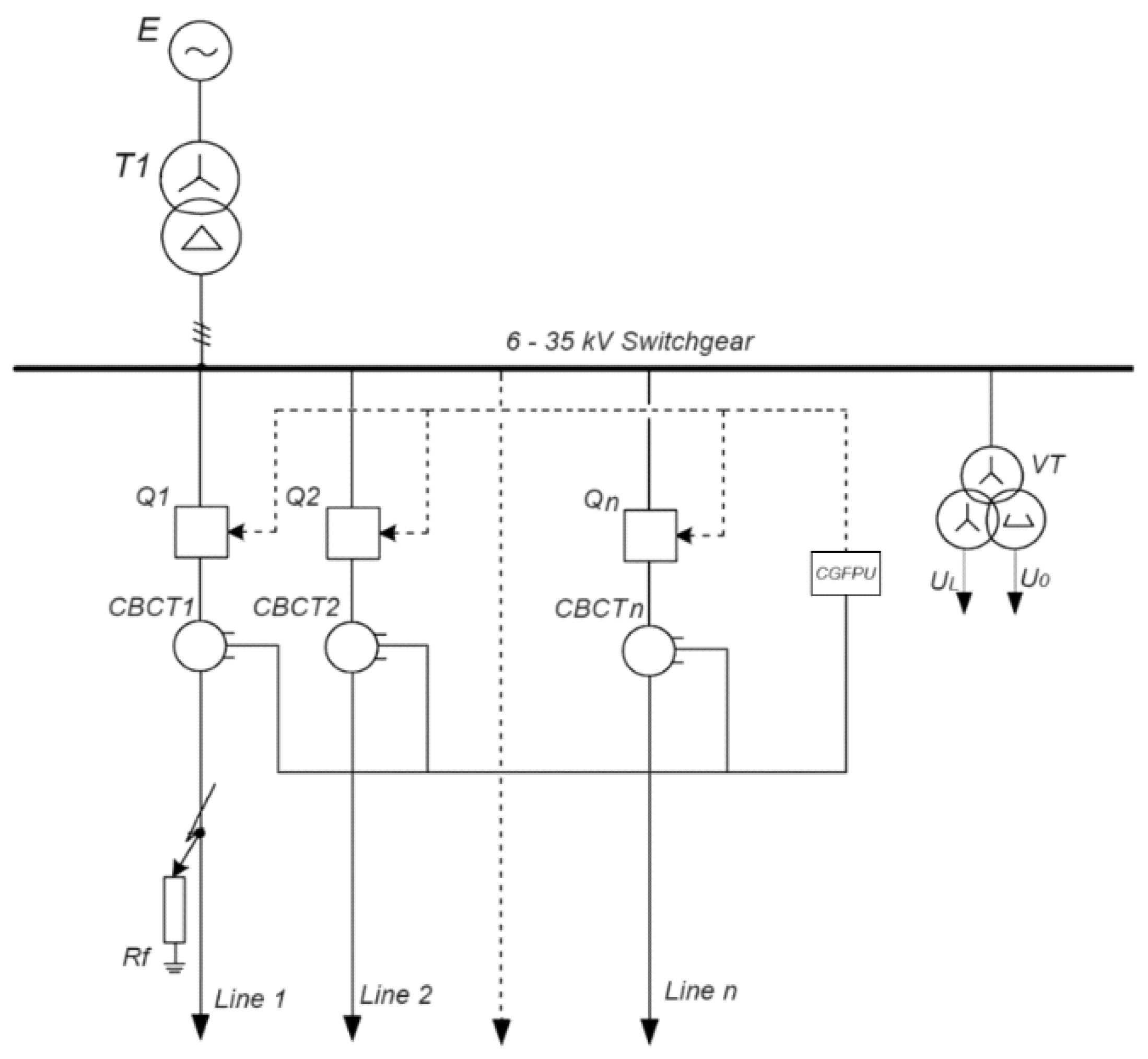
Figure 2.
Phasor diagrams of voltages and currents in normal mode and during GF.
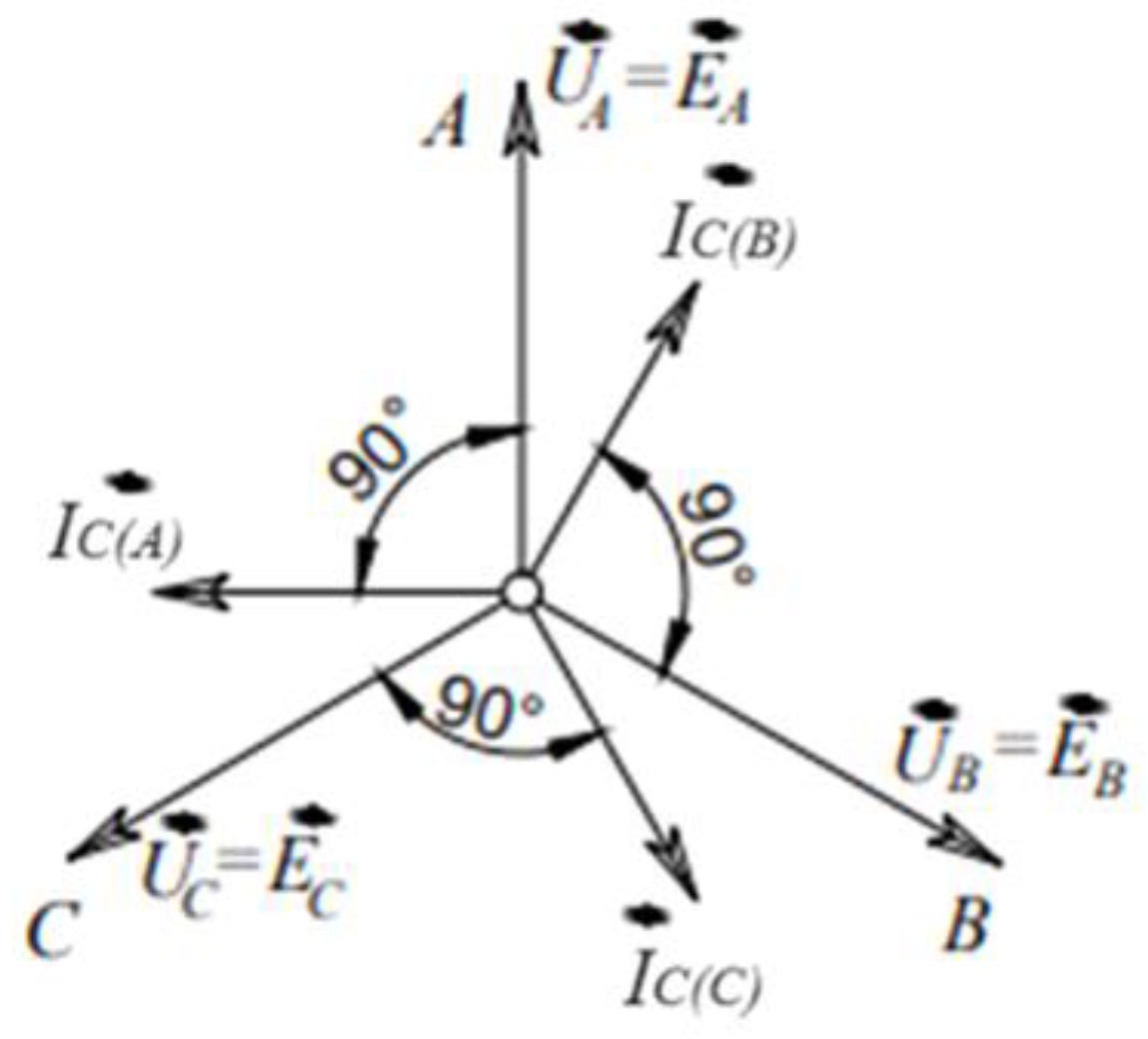
Figure 3.
Calculated equivalent circuit diagram of the distribution network.
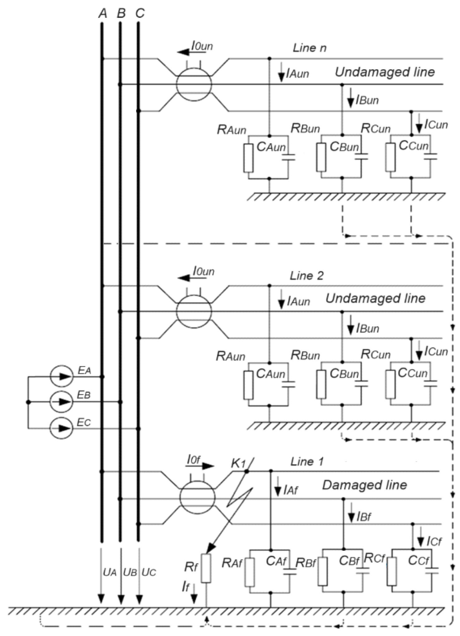
Figure 4.
Vector diagrams of voltages and currents at GF.

Figure 5.
Number of ground faults and transient resistance values at the ground fault location of the 10 kV network.
Figure 5.
Number of ground faults and transient resistance values at the ground fault location of the 10 kV network.
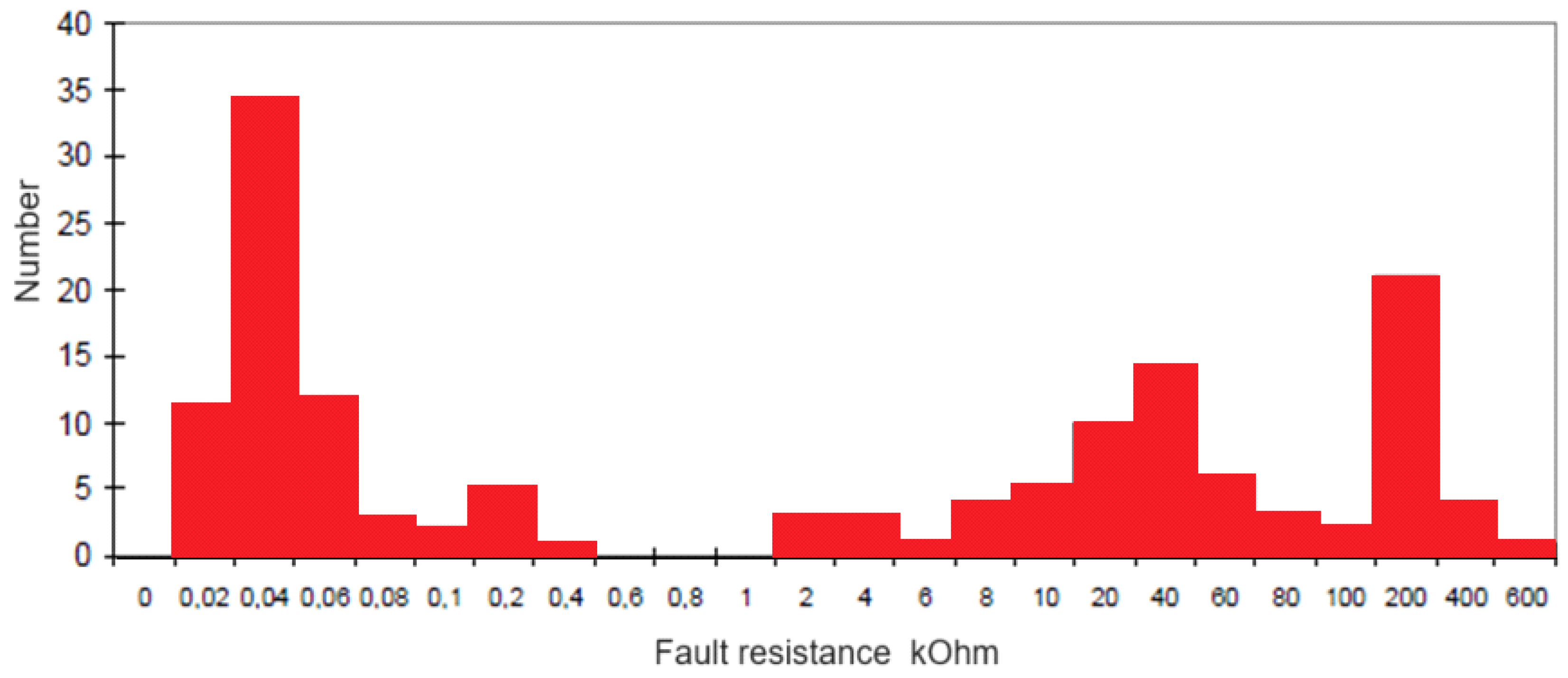
Figure 6.
Impact of transient resistance on zero-sequence currents and voltages at the ground fault location.
Figure 6.
Impact of transient resistance on zero-sequence currents and voltages at the ground fault location.
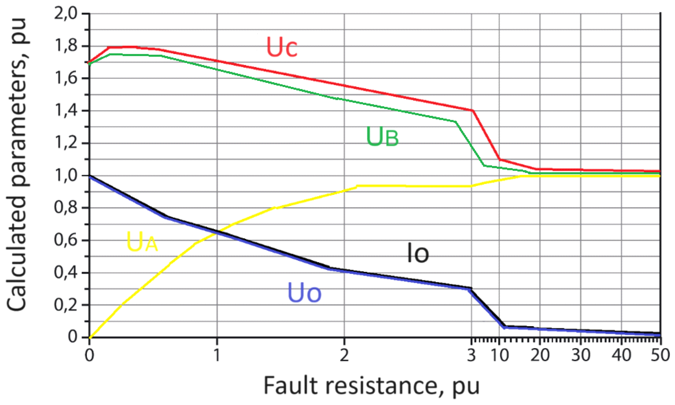
Figure 7.
Zero-sequence equivalent circuit.
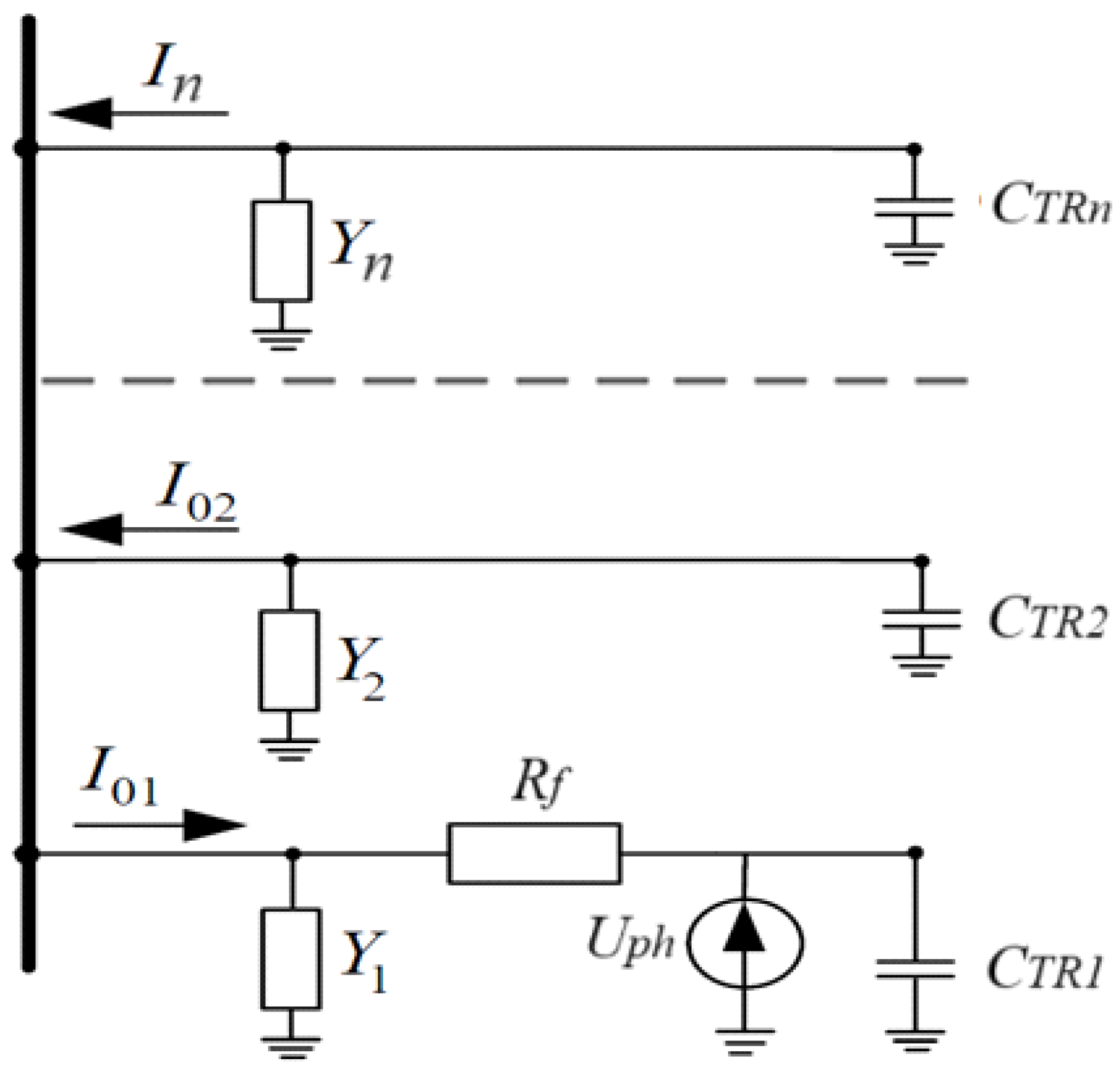
Figure 8.
Dependency of the sensitivity factors on the transient resistance values at the ground fault location at CΣ = 0.1 and Ks = 1.25.
Figure 8.
Dependency of the sensitivity factors on the transient resistance values at the ground fault location at CΣ = 0.1 and Ks = 1.25.
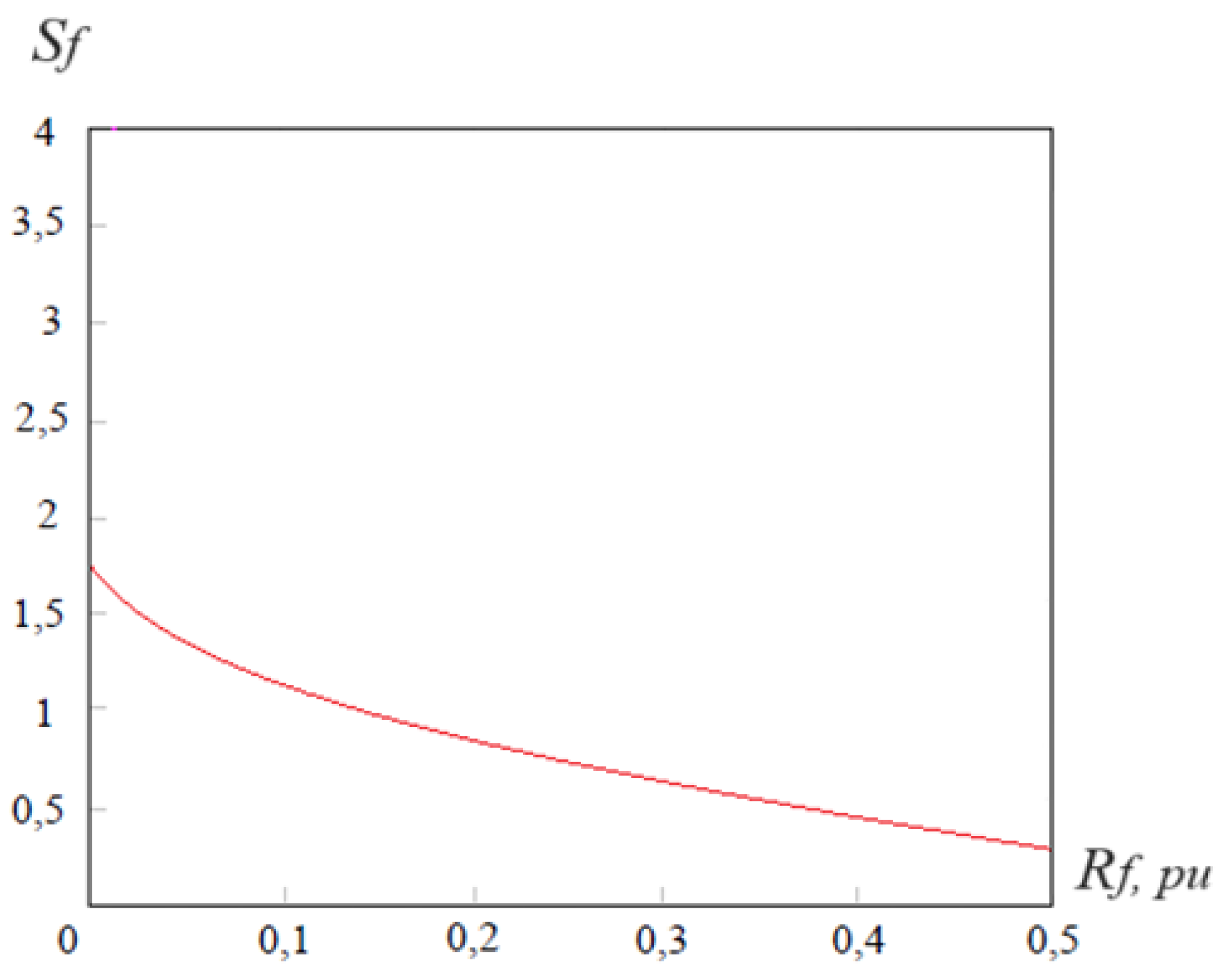
Figure 9.
Functional block diagram of the ground fault protection.
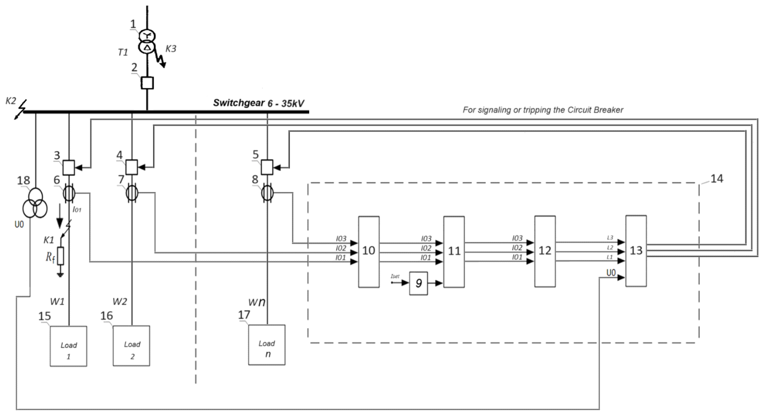
Figure 10.
Algorithm of operation of the centralized ground fault protection unit during ground faults through the transient resistance.
Figure 10.
Algorithm of operation of the centralized ground fault protection unit during ground faults through the transient resistance.
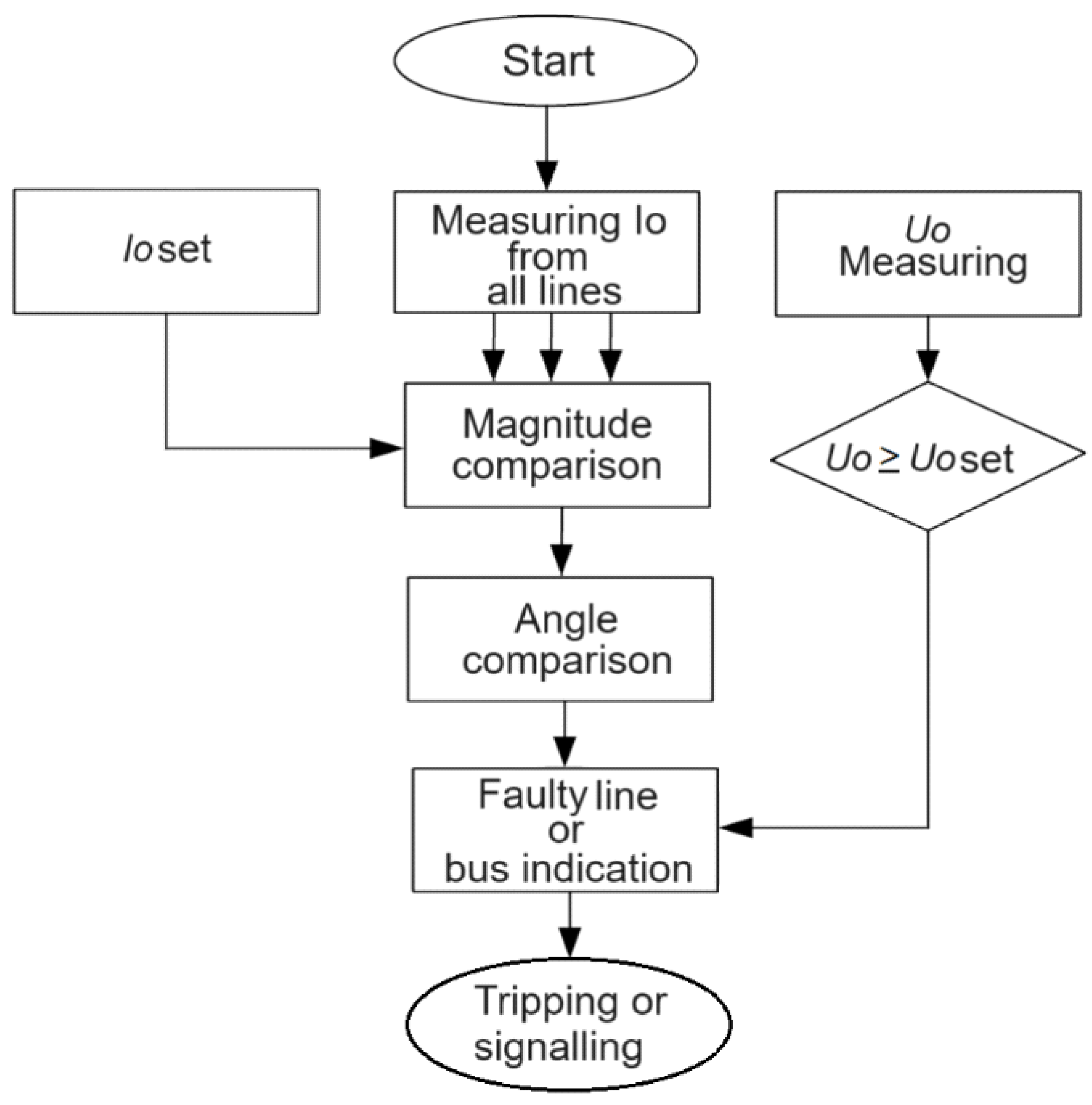
Figure 11.
Phasor diagram of zero-sequence current and capacitive currents during line fault.
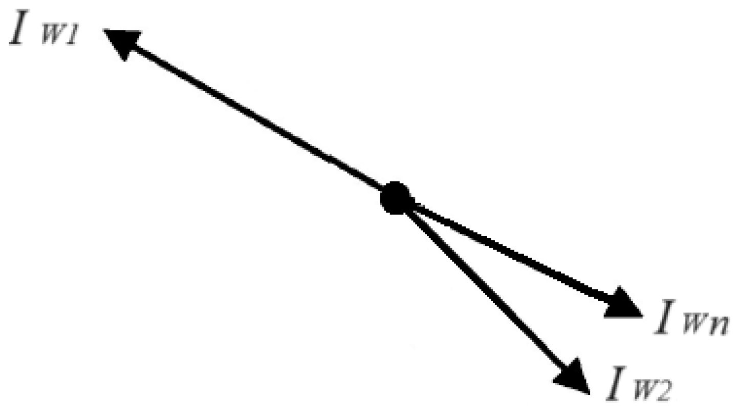
Figure 12.
Phasor diagram of zero-sequence currents and voltages during busbar faults.
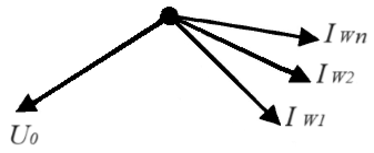
Figure 13.
Ground fault protection device.
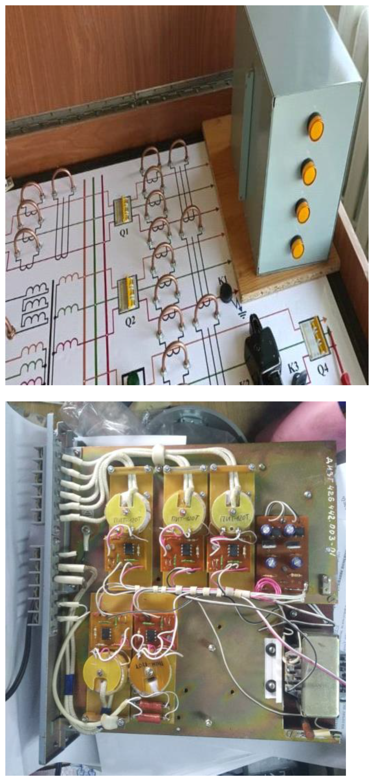
Figure 14.
“Physical model of 6-35 kV networks” Test bench.
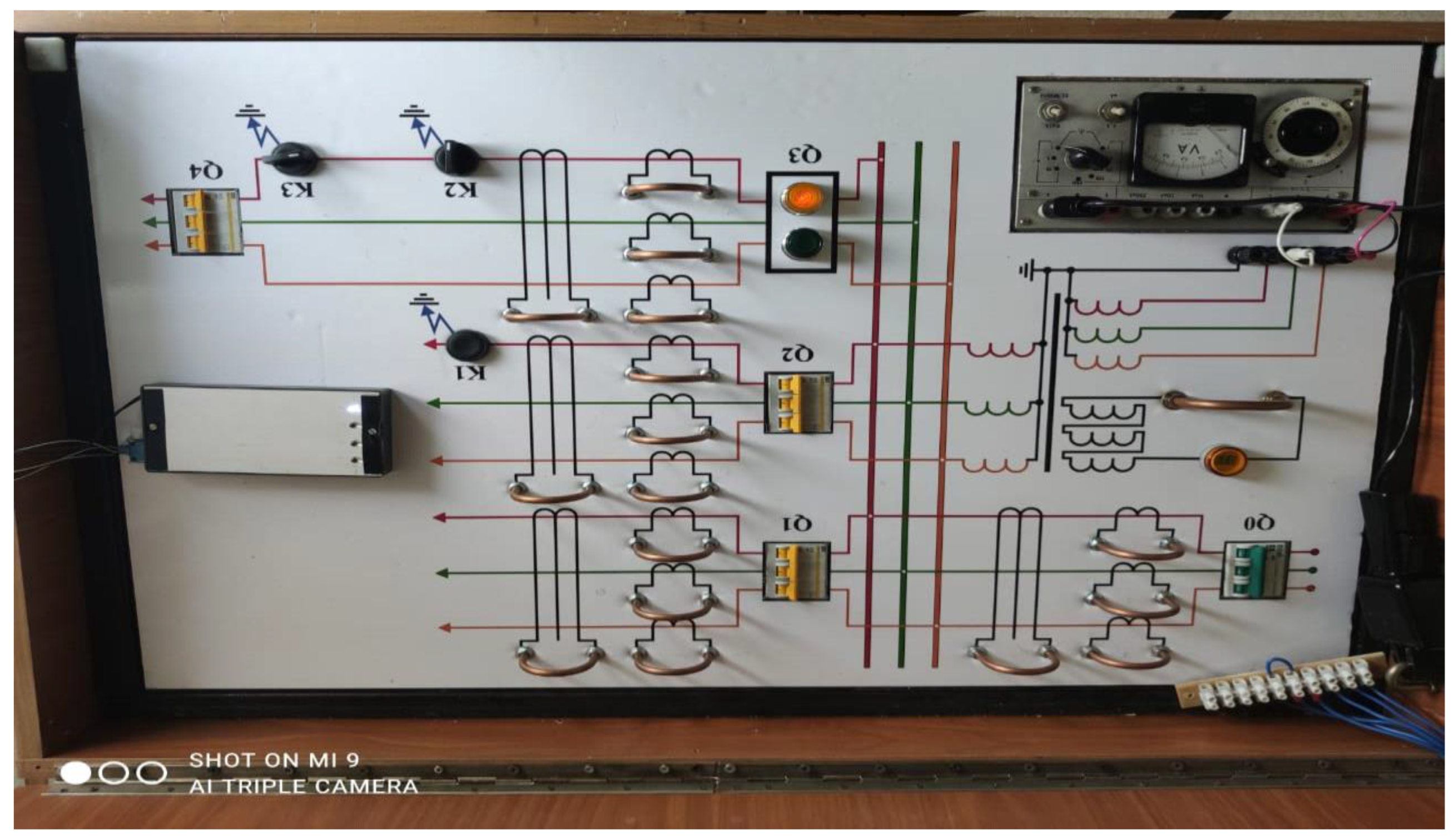
Figure 15.
Phasor diagrams of phase currents, zero-sequence currents and voltages in the normal mode.
Figure 15.
Phasor diagrams of phase currents, zero-sequence currents and voltages in the normal mode.
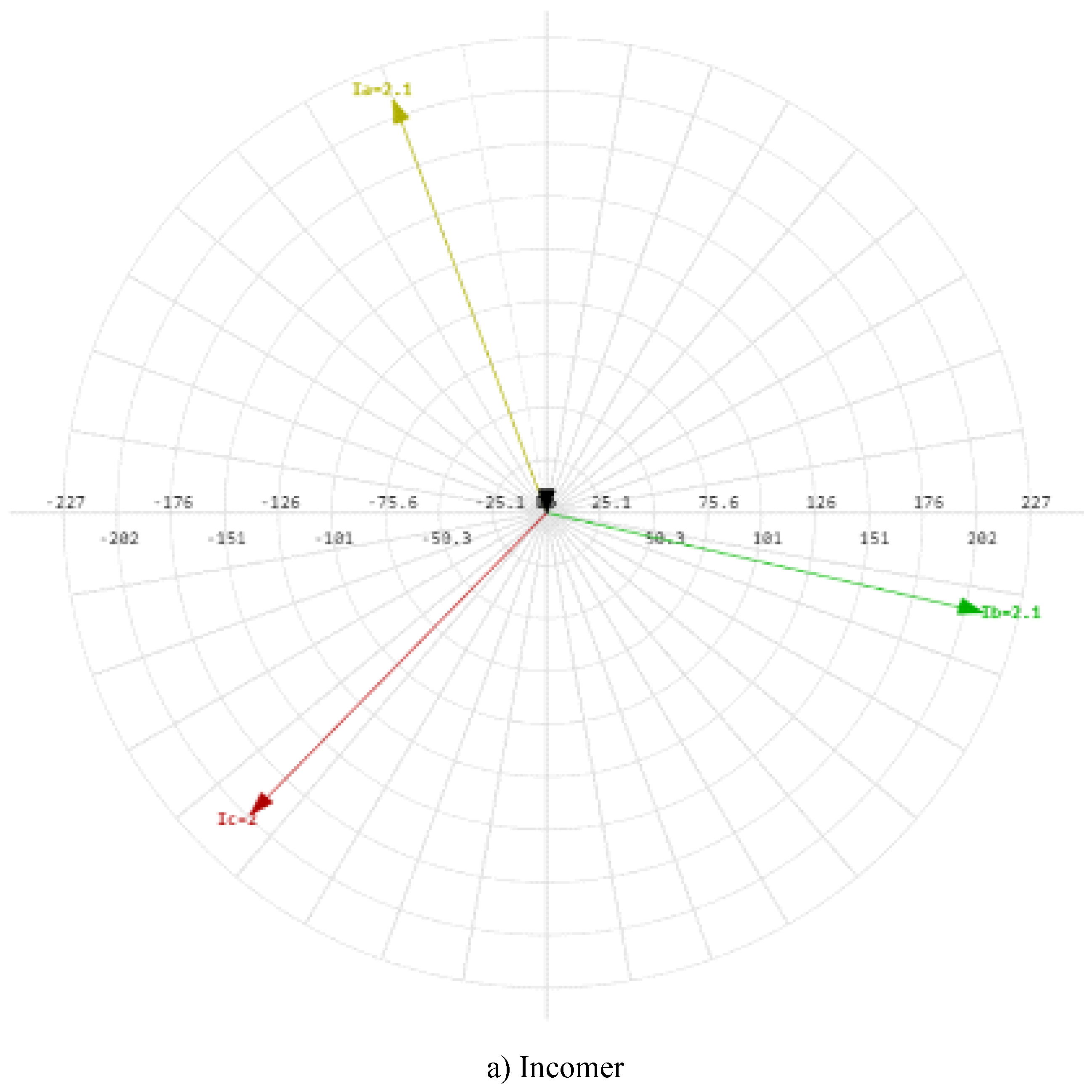
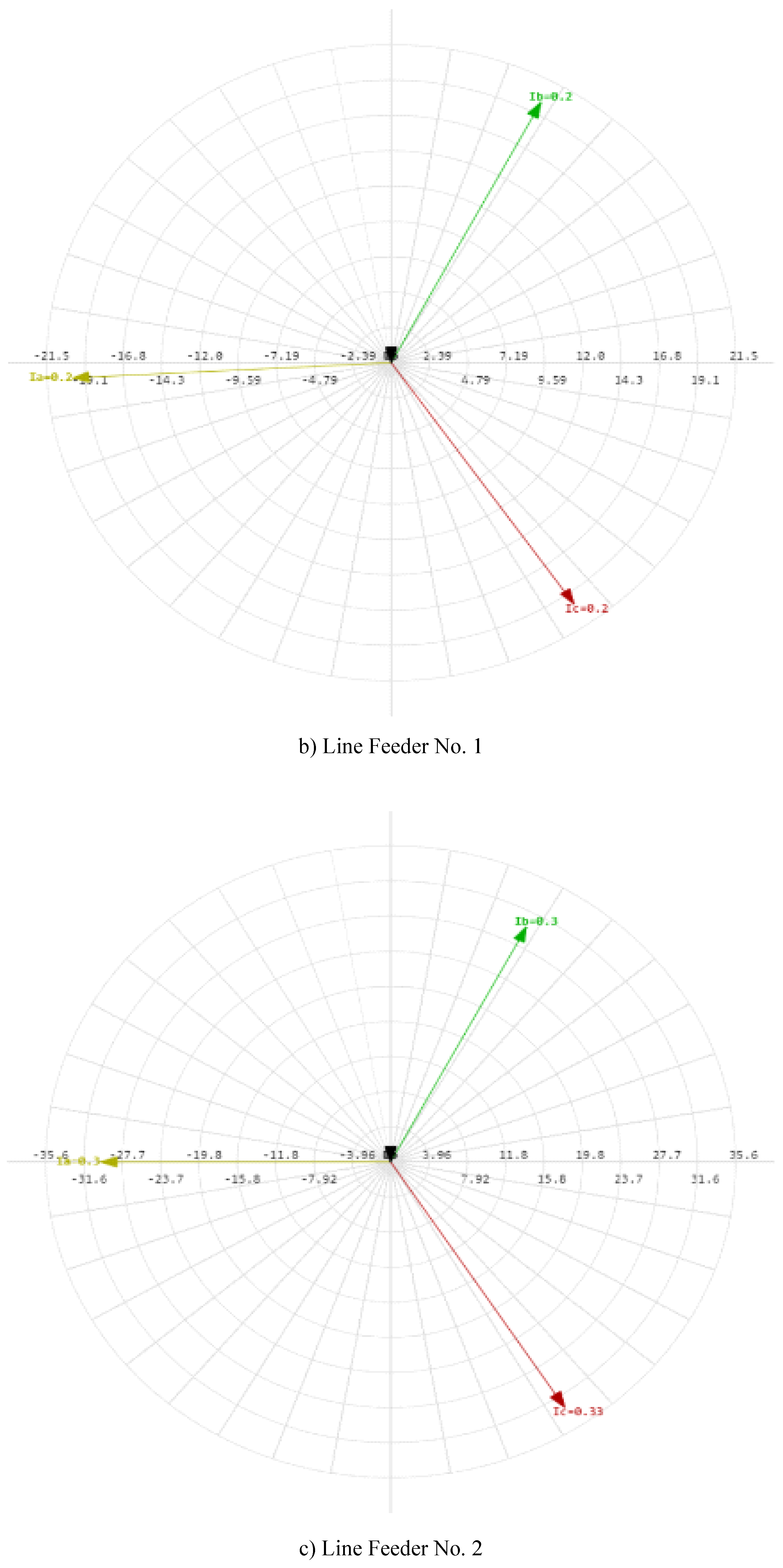
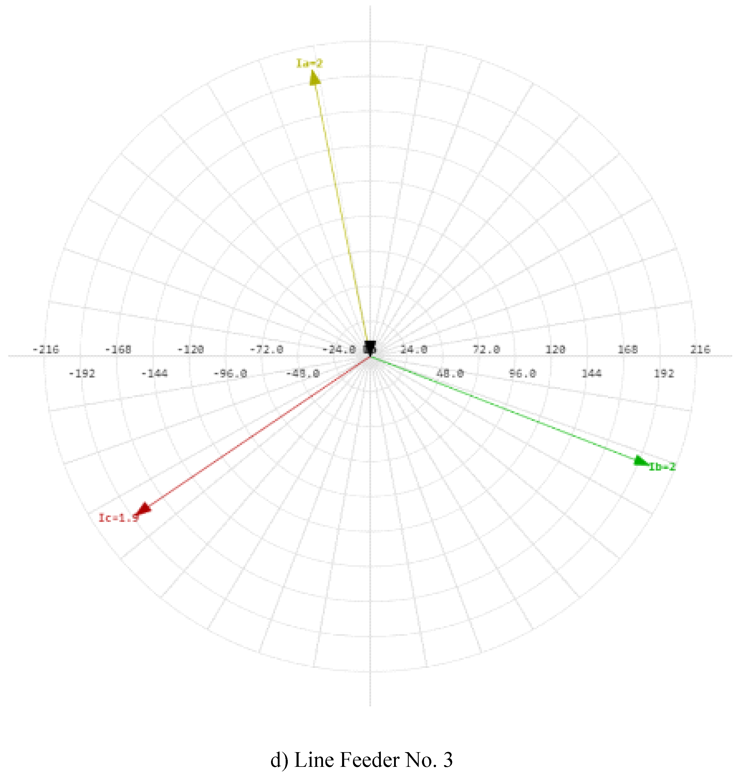
Figure 16.
Phasor diagrams of phase currents, zero-sequence currents and voltage during a ground fault on C phase at the beginning of the line No. 2 at the point K1.
Figure 16.
Phasor diagrams of phase currents, zero-sequence currents and voltage during a ground fault on C phase at the beginning of the line No. 2 at the point K1.
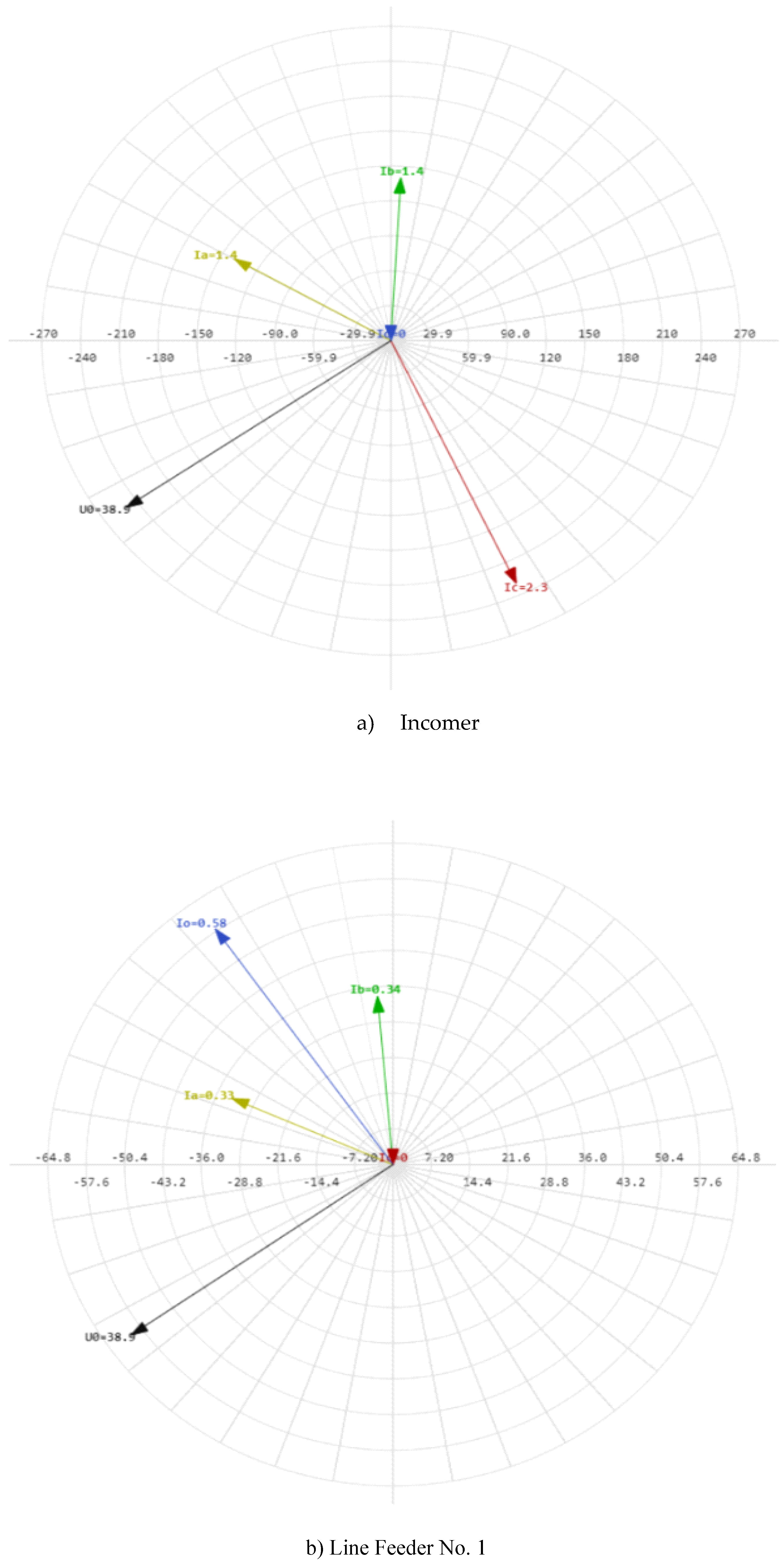
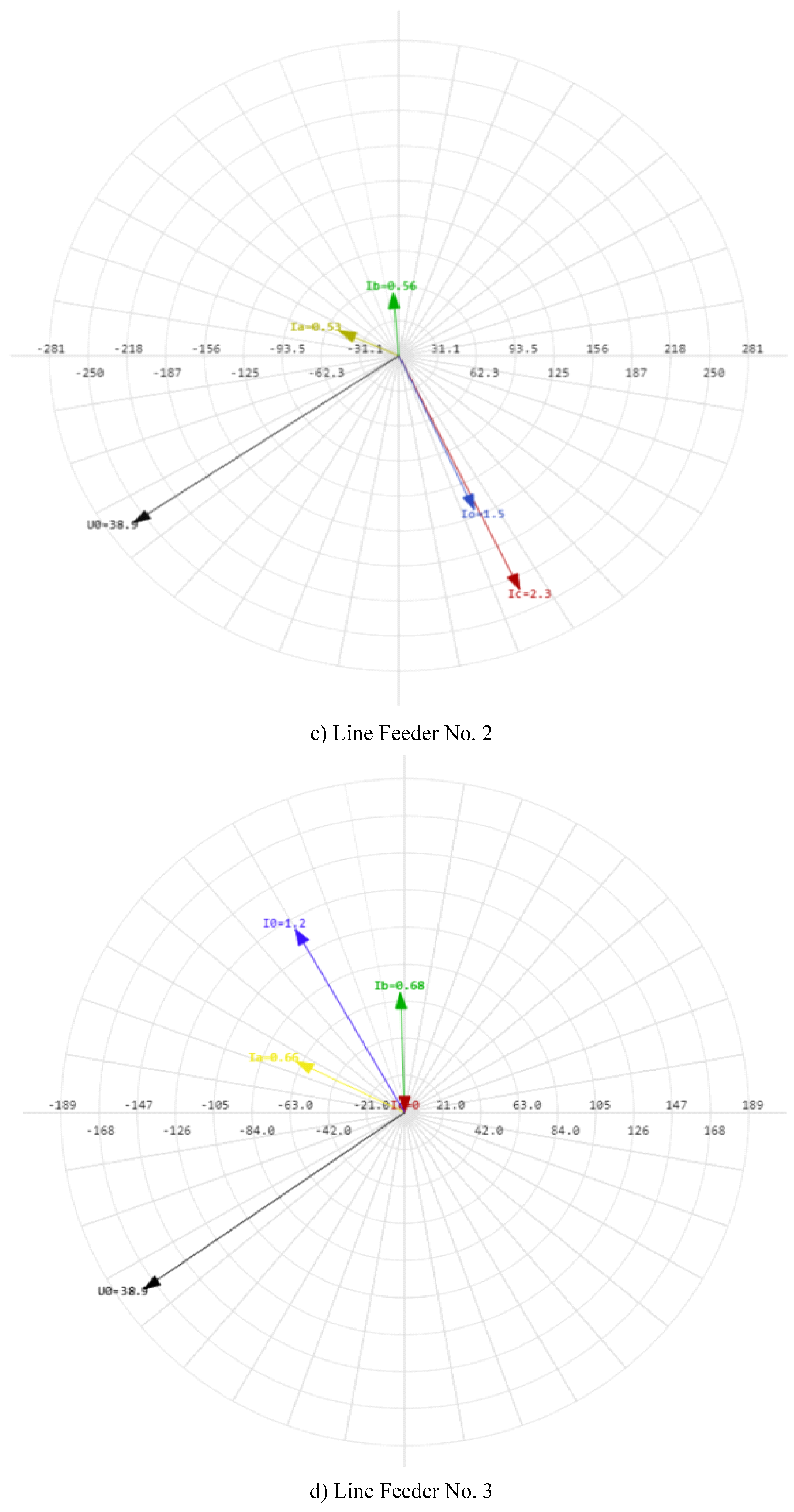
Figure 17.
Phasor diagrams of phase currents, zero-sequence currents and voltages for a ground fault on C phase at the beginning of line No. 3 at the point K2.
Figure 17.
Phasor diagrams of phase currents, zero-sequence currents and voltages for a ground fault on C phase at the beginning of line No. 3 at the point K2.
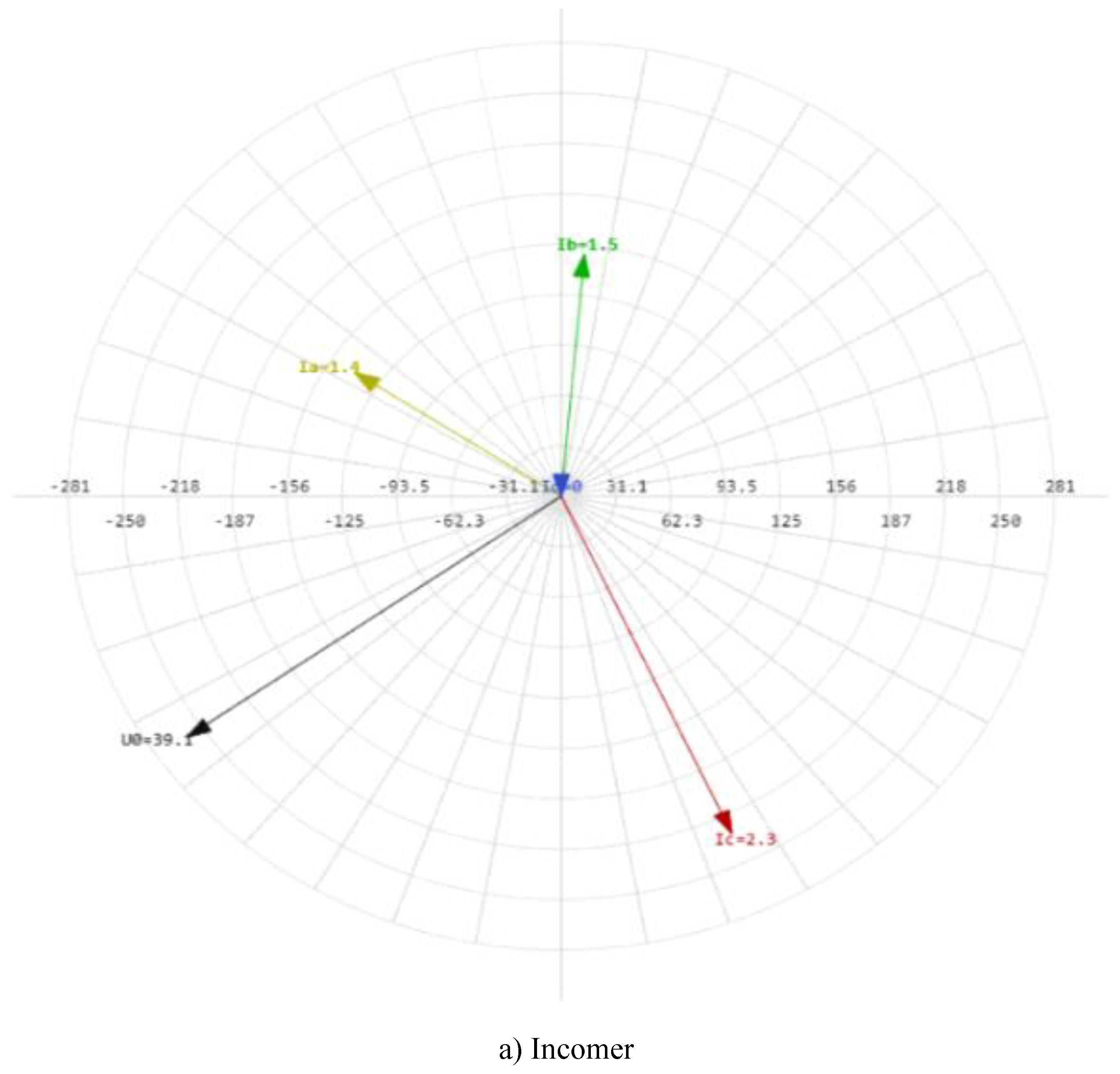
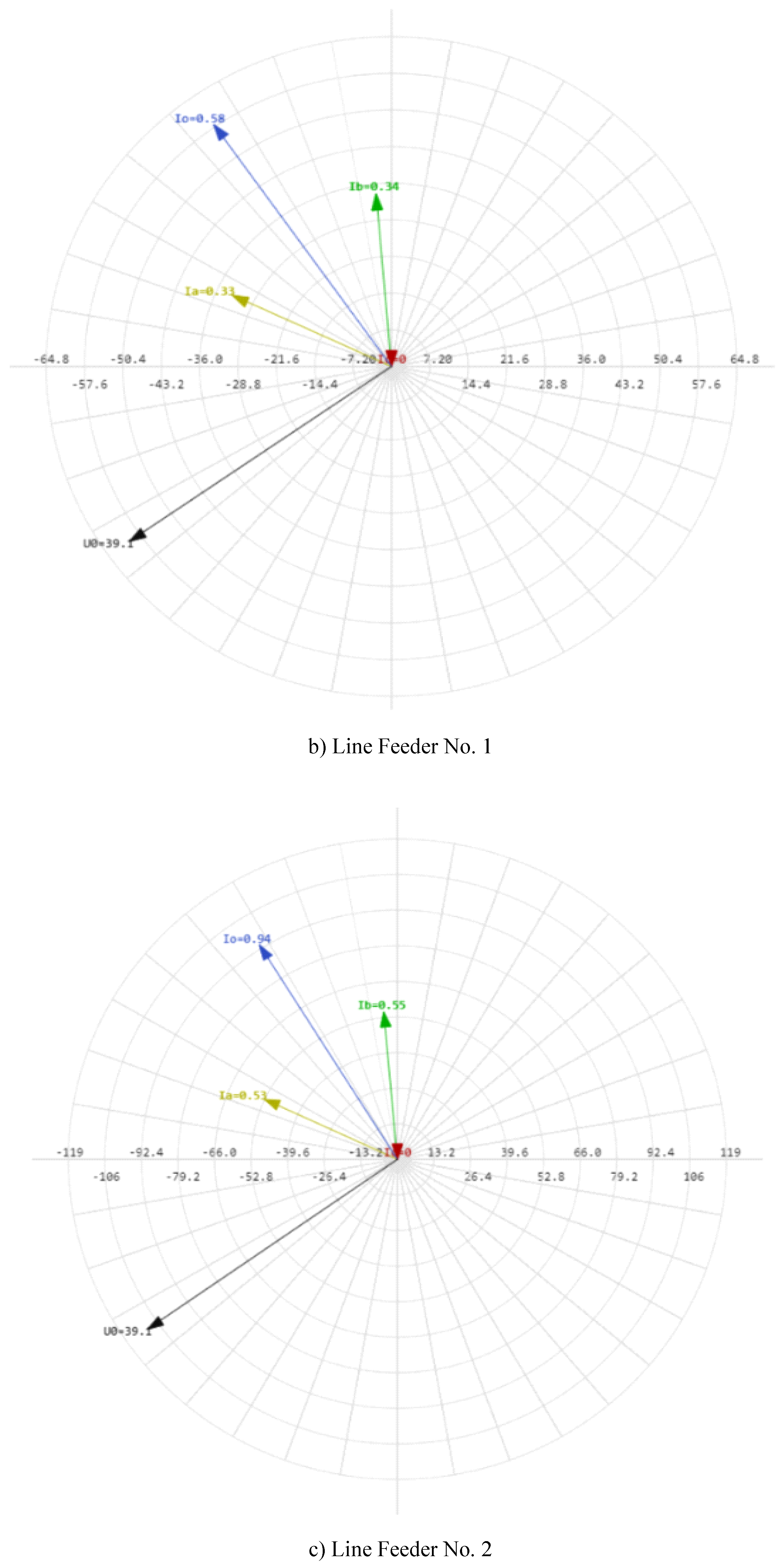
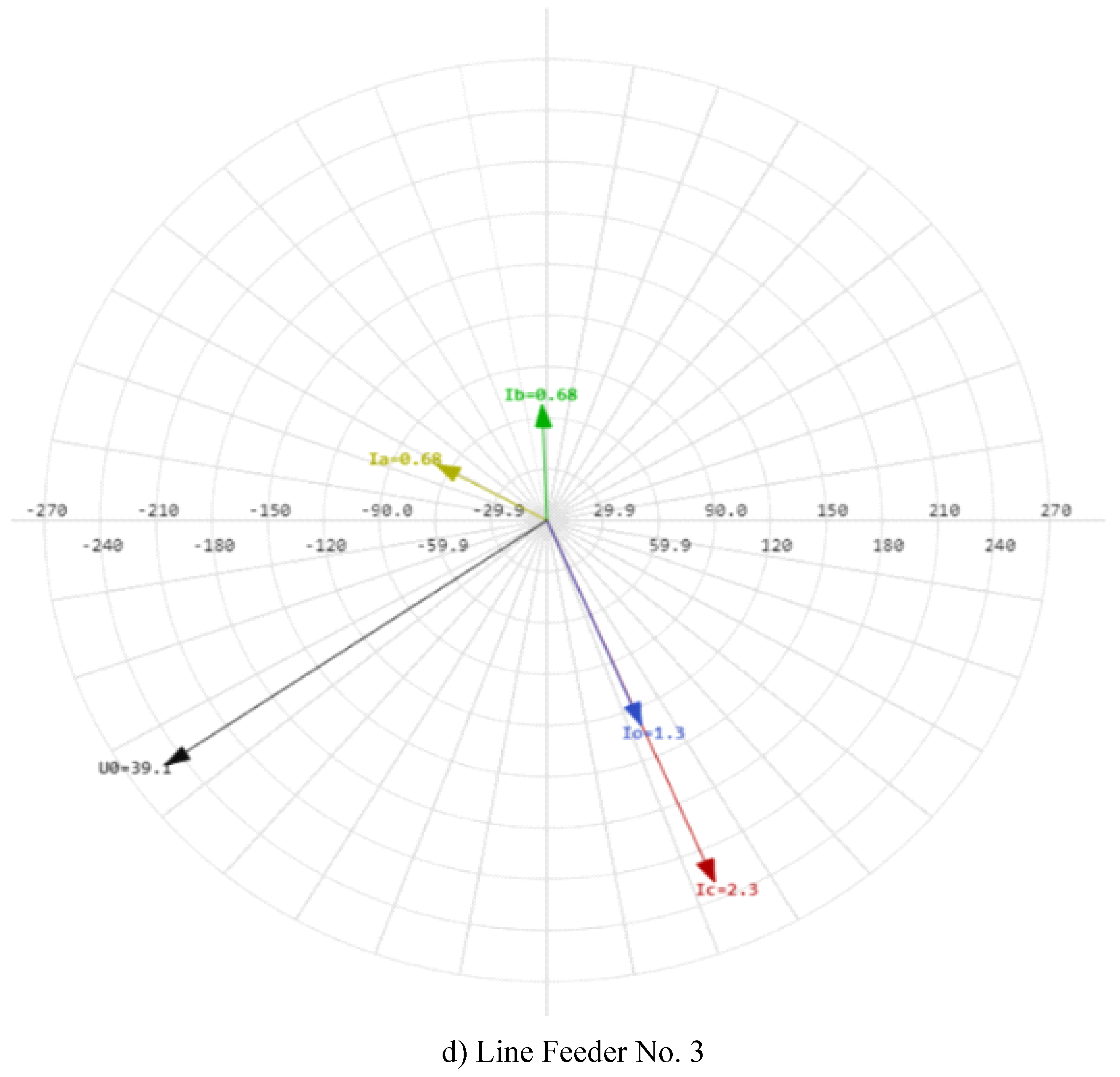
Figure 18.
Phasor diagrams of phase currents, zero-sequence currents and zero-sequence voltages during a ground fault on C phase at the end of line No. 3 at the point K2.
Figure 18.
Phasor diagrams of phase currents, zero-sequence currents and zero-sequence voltages during a ground fault on C phase at the end of line No. 3 at the point K2.
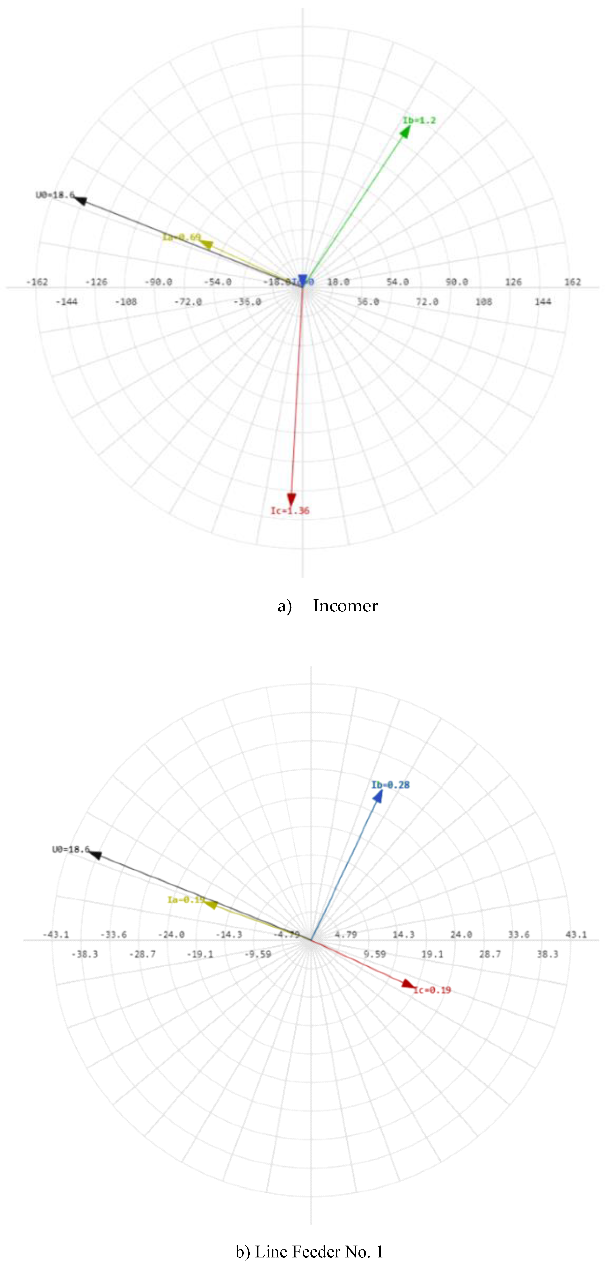
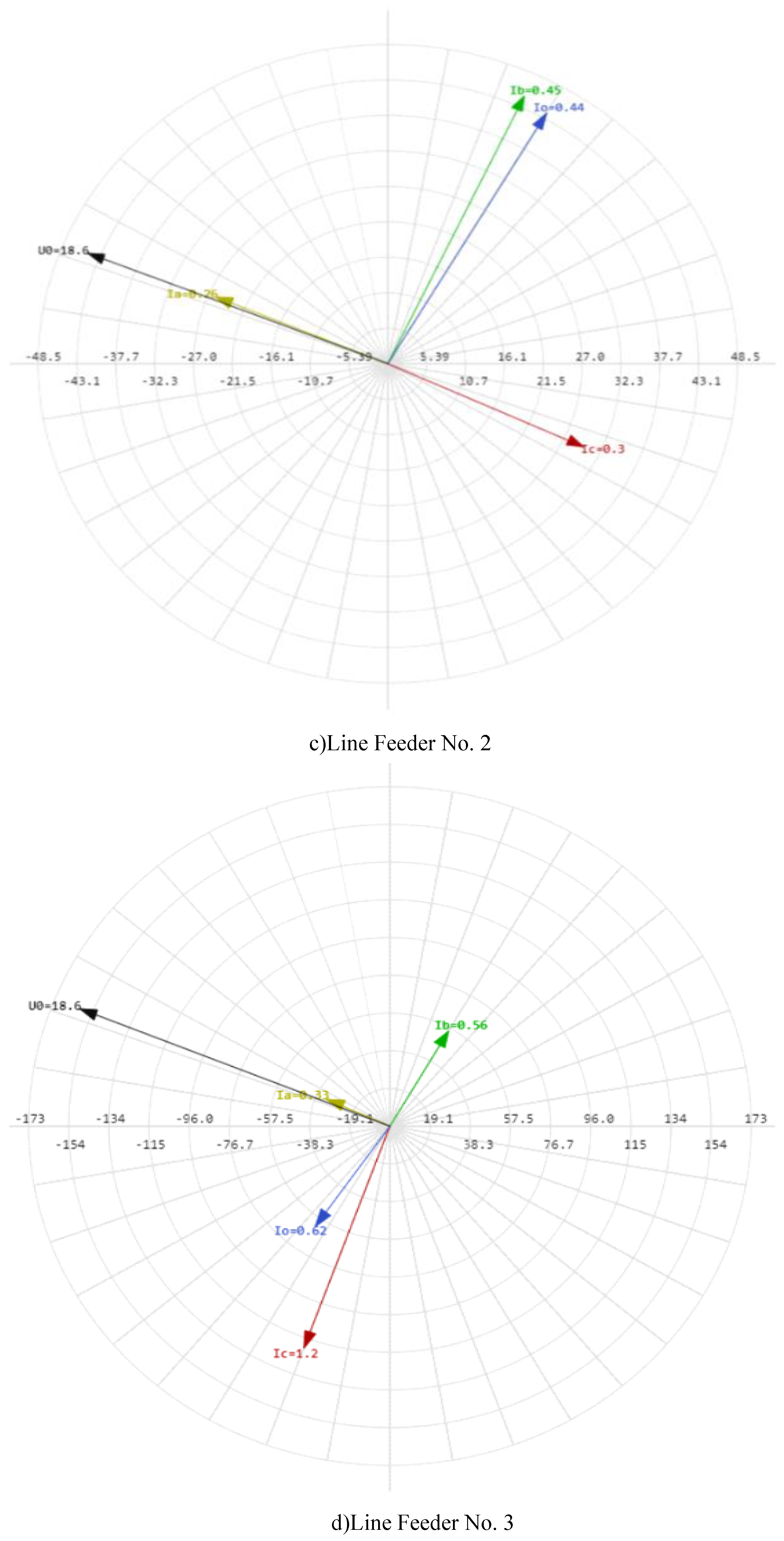
Figure 19.
Protection operation during the ground fault on the line.
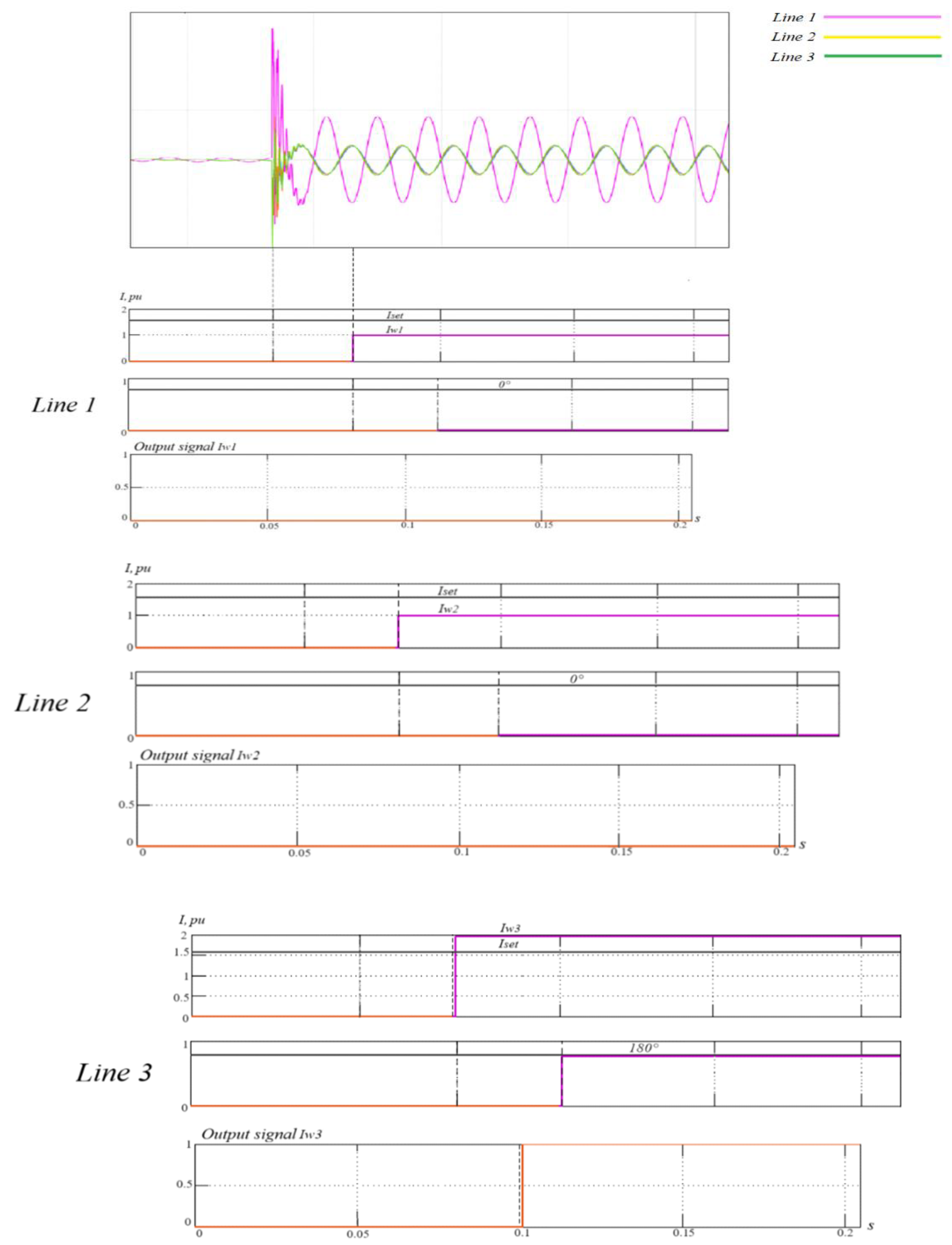
Figure 20.
Operation of protection during bus ground fault.
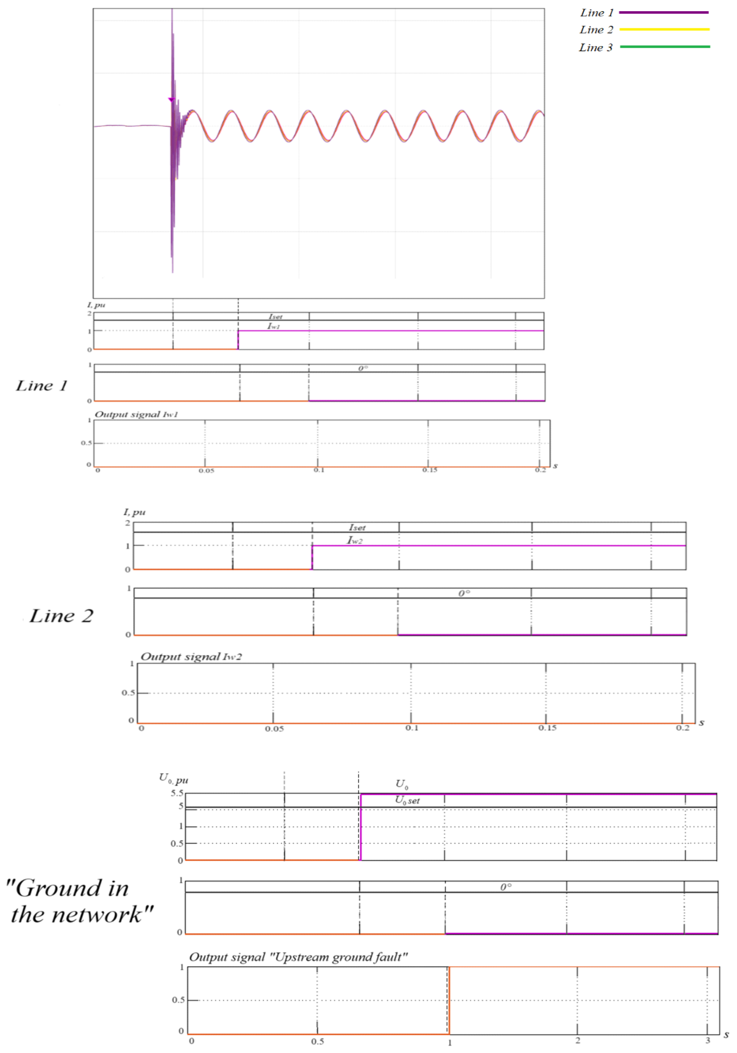
Figure 21.
Maximum Torque Angle for ground fault protection during line ground fault.
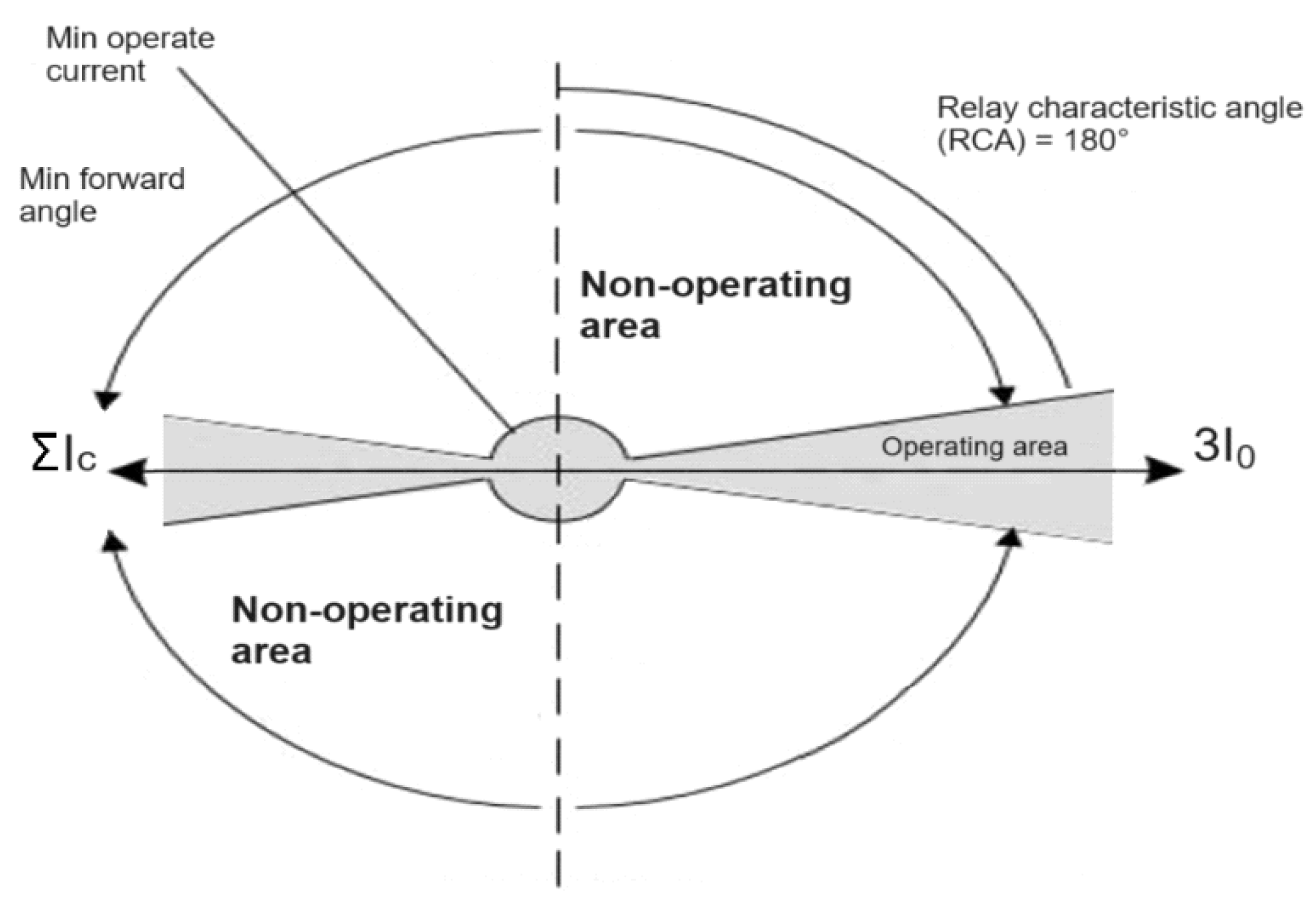
Figure 22.
Maximum torque angle for ground fault protection during upstream bus ground fault.
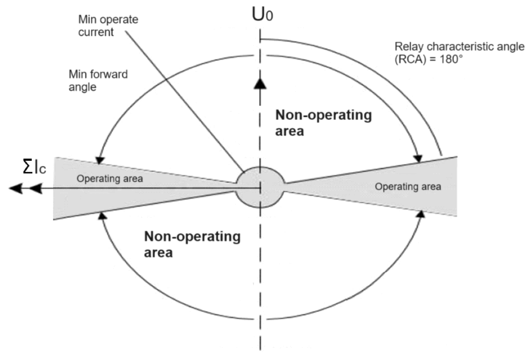

Table 1.
Results of experiments with ABC load.
| Mode | Normal mode | K1 (at the beginning of the line) Feeder 2 |
K2 (at the beginning of the line) Feeder 3 |
K3 (at the end of the line with transient resistance) Feeder 3 |
|
|---|---|---|---|---|---|
|
Incomer |
2.1 | 1.4 | 1.4 | 0.69 | |
| +20° | +60° | +57 | +65 | ||
| 2.1 | 1.4 | 1.5 | 1.2 | ||
| -103° | -3° | -5 | -33 | ||
| 2.0 | 2.3 | 2.3 | 1.36 | ||
| +136° | -155° | -155 | +177 | ||
| 0 | 0 | 0 | 0 | ||
| 0 | 0 | 0 | 0 | ||
| 0 | 38.9 | 39.1 | 18.6 | ||
| 0 | +125° | +125° | +68° | ||
|
Feeder 1 |
0.2 | 0.33 | 0.33 | 0.19 | |
| +93° | +66° | +65° | +70 | ||
| 0.2 | 0.34 | 0.34 | 0.28 | ||
| -28° | +5° | +5° | -25 | ||
| 0.2 | 0 | 0 | 0.19 | ||
| -145° | 0 | 0 | -115 | ||
| 0 | 0.58 | 0.58 | 0.28 | ||
| 0 | +35° | +35° | -25 | ||
|
Feeder 2 |
0.3 | 0.53 | 0.53 | 0.26 | |
| +90° | +65° | +65° | +67 | ||
| 0.3 | 0.56 | 0.55 | 0.45 | ||
| -28° | +5° | +5° | -25 | ||
| 0.33 | 2.3 | 0 | 0.3 | ||
| -147° | -155° | 0 | -115 | ||
| 0 | 1.5 | 0.94 | 0.44 | ||
| 0 | -156° | +32° | -30 | ||
|
Feeder 3 |
2 | 0.66 | 0.68 | 0.33 | |
| +11° | +64° | +61° | +65° | ||
| 2 | 0.68 | 0.68 | 0.56 | ||
| -112° | +2° | +2° | -30° | ||
| 1.9 | 0 | 2.3 | 1.2 | ||
| +125° | 0 | -157° | +160° | ||
| 0 | 1.2 | 1.3 | 0.62 | ||
| 0 | +30° | -157° | +145° |
Disclaimer/Publisher’s Note: The statements, opinions and data contained in all publications are solely those of the individual author(s) and contributor(s) and not of MDPI and/or the editor(s). MDPI and/or the editor(s) disclaim responsibility for any injury to people or property resulting from any ideas, methods, instructions or products referred to in the content. |
© 2024 by the authors. Licensee MDPI, Basel, Switzerland. This article is an open access article distributed under the terms and conditions of the Creative Commons Attribution (CC BY) license (https://creativecommons.org/licenses/by/4.0/).
Copyright: This open access article is published under a Creative Commons CC BY 4.0 license, which permit the free download, distribution, and reuse, provided that the author and preprint are cited in any reuse.


