
Submitted:
12 December 2024
Posted:
13 December 2024
You are already at the latest version
Abstract
The operation process of the double-pendulum ship-borne cranes with variable rope length is frequently quite complex, with numerous unpredictable circumstances, such as the swing of the load and external environmental interference, which will undoubtedly make the analysis of the swing characteristics of the system and the controller design more difficult. On this basis, an active disturbance rejection controller based on energy coupling method is proposed to inhibit the double-pendulum swing angles. Firstly, the energy function of the system is constructed by analyzing the dynamic model of the system, and then an adaptive control method is designed by analyzing the energy function of the system. In addition, an overshoot limit term and an anti-swing term are added to limit the overshoot and the swing of underactuated parts of the system. Then, the stability of the closed loop system is strictly proved by using Lyapunov analysis method. Finally, the simulation and experiment results indicate that the proposed controller ensures accurate positioning of the jib and rope length without overshoot. Additionally, it effectively reduces the double-pendulum swing angles when there is external interference such as waves, demonstrating strong robustness.
Keywords:
Adaptive control
; Underactuated system
; Ship-borne crane
; Anti-swing control
1. Introduction
Mast cranes are commonly applied industrial installation near modern ports. The ship-borne cranes are usually mounted on the ship, which may disturbed by throbbing waves, drifting wind, cable corrosion, etc. during cargo transportation process. Because the ship-borne crane works in a harsh marine environment, the current manual operation is dangerous, and the accuracy of control is easily influenced by environmental factors, so it is essential to design a controller to manage the operation of the crane. The mechanical structure and working principle of ship cranes are similar to those of typical land fixed cranes, however, they exhibit stronger state-variable coupling and more complex dynamic characteristics. Additionally, unlike land fixed cranes, there have hull motions with multiple degrees of freedom in marine environment, which increase the difficulty and challenges of controlling ship-borne cranes [1]. Nowadays the ship-borne crane with double pendulum takes more effects in the ocean engineering, the research of its advanced control method is very meaningful.
The problem of control of land fixed cranes has been studied extensively over the past few decades, such as optimal control [2,3,4], nonlinear control [5,6,7,8,9,10], and intelligent control [11,12,13,14,15,16,17,18]. Currently available methods include open-loop control methods, closed-loop control methods, and sliding mode control, etc. Compared to the single-pendulum crane, the double-pendulum crane system has more motion dimensions and stronger coupling, making it more difficult to eliminate load sway. In the case of the double pendulum effect, the traditional method applied to the single-pendulum crane system is difficult to achieve a good control effect. For this reason, in recent decades, the control problem of ship-borne cranes has attracted more and more attention, and many remarkable research results have been presented.
For ship-borne crane systems, in [19], Ren et al. propose a general model-free anti-swing control scheme that simplifies the control process by not requiring state-space equations. This approach effectively minimizes the motion of a pendular payload, regardless of the specific system configuration. Zhao et al. propose a sliding mode anti-swing controller in [20], and subsequently developed an enhanced adaptive sliding mode cooperative controller. In [21], Wu et al. introduce an adaptive controller capable of updating its adaptive laws in real time based on the system’s state and disturbances. Considering the issue of residual swing of the load, Chen et al. propose a time-optimal trajectory planning method for the offshore crane in [22]. Yang et al. present an adaptive control method utilizing neural networks to address the issue of nonlinear input dead zones [23]. In [24], Kuchler et al. propose an dynamic compensation system for the vertical vessel motion. Taking into account the nonlinear system of the offshore ship crane, along with actuator malfunctions and external interferences, Guo et al. propose an innovative event-triggered fuzzy robust fault-tolerant control approach [25]. In [26], Qian et al. develop a new adaptive robust coupling control method that integrates adaptive laws to handle unknown parameters.
Considering the control issues associated with dual ship-borne crane system, Hu et al. develope two energy-based nonlinear controllers, consisting of a full-state feedback control approach and an output feedback control approach [27]. Considering the scenario of jib rotation and horizontal transfer, Qian et al. present an innovative control scheme based on nonlinear switching logic for marine cranes [28]. Taking into account the complex disturbances caused by ship motions, Wu et al. introduce a novel adaptive dynamic output feedback control approach [29]. In [30], Kim et al. develop a tracking controller for cranes installed at mobile harbors, which features a dual-stage trolley system capable of dynamically positioning containers between the mobile harbor and the container ship, and vice versa. Considering the underwater working environment, Wang et al. develope a nonlinear control method based on a coupling characteristic indicator [31]. In [32], Chen et al. introduce an innovative hierarchical control strategy to address the challenge of active heave compensation for onboard offshore cranes during heavy lifting operations in harsh marine environments. In the context of ship-to-ship load transfer using offshore cranes, Bozkurt et al. propose an innovative control strategy that integrates a combined vertical, horizontal, and anti-swing control system [33].
In general, based on the analysis of the above literature, this paper proposes an energy-based adaptive controller for ship-borne cranes with double pendulum effect. Specific innovation points are summarized as follows:
1) For a ship-borne crane with double pendulum effect, an adaptive controller has been designed. Using the adaptive term, the uncertain friction of the actuator can be estimated online, effectively eliminating the positioning error of the jib and the load.
2) To address the issue of overshoot, we meticulously designed two overshoot limit terms. By introducing overshoot limit parameters, we constrained the overshoot of the rope length and the jib, ensuring stability and precision in the control process.
The structure of the rest of this paper is outlined as follows. Section II presents the dynamic model transformation of the ship-borne crane system. Section III describes the design process of the adaptive controller. Section IV analyzes the stability of the system. Section V presents the simulations. Section VI concludes the paper.
2. Dynamic Model Transformation
This section establishes the dynamic model of the ship-borne crane, with its schematic diagram in Figure 1. Where, and represent the earth-fixed and ship-fixed coordinates, respectively. and represent the driving force of the jib and rope respectively, respectively represent the jib mass, hook mass and load mass. represents the ship motion angle caused by sea wave. J is the jib rotational inertia. is the jib luffing angle, , and represent the length of the rope, the jib and the distance between the hook and the center of gravity of the load respectively. and represent the swing angle of the hook and the load relative to the vertical direction. The dynamic equation of a ship-borne crane system with variable rope length is shown as follows[21]:
The friction force in (1) and in (2) are respectively expressed in the following forms:
where, represent friction-related parameters. The model presented in (1)-(4) can alternatively be expressed in the following compact form:
where, , . Under the premise of not losing generality, the following assumptions are considered reasonable and are commonly applied in the field of crane control:
Assumption 1 [34]: Considering the practice working condition, the hook and the load are always under the jib, so the swing angle of the hook and the load meet the following conditions:
According to the model given in (1)-(4), a controller with and as driving forces will be designed to solve the control problem of double-pendulum ship-borne crane system through their joint action. Its control objectives are as follows:
where are the corresponding desired values.
3. Controller Design
This section introduces the design procedure for the adaptive controller of double-pendulum ship-borne crane. To enable further analysis and the design of control laws, the following two error signals are introduced:
For convenience, let’s define . Then construct a energy-like function as follows
Derivation of Formula (11) gives:
By substituting Formulas (1)–(4) into Formula (12), we can get
where,
To integrate the control objective into the controller design, we further define the following continuously differentiable positive definite scalar function based on Equation (11).
Where, represent the positive control gain, represents a positive definite diagonal matrix, represents positive control gain, are positive adjustable gains, represent error estimation vectors.
where, are the online estimation signals of , respectively.
By taking the derivative of Formula (15) and combining with Formulas (1)–(4), (12) and (16), we can get:
Therefore, the following preliminary control law is given as:
where, , represent positive control gains, represent the updating laws, are designed as follows:
Then, the controller (18)-(19) do not incorporate relevant information about the double pendulum angles. Furthermore, like most feedback control methods, the control law may be overshot. Therefore, the adaptive controller is ultimately proposed as follows:
where, represent the positive control gains, , are incorporated to limit the maximum overshoot of and , respectively. The flowchart of the overall control system is shown in Figure 2.
4. Closed-Loop System Stability Analysis
In this section, we conduct a stability analysis of the proposed controller. By using Lyapunov function and LaSalle’s invariance theorem, the asymptotic stability of the system is proved.
According to the designed adaptive controllers in the Formula (21) and the Formula (22) and the updating laws in the Formula (20), it can ensure that the jib and rope attain the desired position while preventing the hook and load from swinging. These results are described mathematically as follows:
Synchronously, the angle of the jib and the length of the lifting rope should not exceed and , and the overshoot of is less than and , respectively.
Initially, create the Lyapunov function as follows:
Then, taking the derivative of V in Equation (26) and substituting it into Equations (13), (16) and (20), we can get the following result as:
By substituting Equations (20)–(22) into Equations (27), we get:
This shows that:
Since , suppose that and tend to go beyond the boundaries of and , respectively, then it is clear from (26) that , which is in contradiction with , therefore,
From (28), it is evident that the closed-loop system is Lyapunov stable. We can further conclude that:
To prove the Formulas (23) and (24), let be the largest invariant set contained in , and define as:
As can be seen from (14),(28) and (30), we can obtain that in ,
where, , are constants that need to be established. Combined with (21)-(22) and (33), we can get that
That is, and remain the same in . Substituting Equation (33) into Equation (1) yields:
That is
The integral of (38) is calculated as follows:
where, is a constant to be determined. If , then when ,
which contradicts with and . According to Equations (33)–(36) and (39), in ,
Then, by combining and , we can rewrite (35) as follows:
Since , we have , indicating that the parentheses in Equation (43) are always positive. Thus, from (33) and (43) :
By substituting (33) into (2)-(4), and simplifying the process, we can get:
where, .
Then, by multiplying both sides of (45) with , multiplying both sides of (46) with , and calculating the sum of the two new equations, it can be concluded that
Further, by multiplying both sides of (48) with , multiplying both sides of (47) with . Then, after mathematical calculation, we can get that
By plugging (49) into (41) and integrating both sides of (41), we get the result:
Where, is a constant. Similarly, if supposing , then the left-hand side of (50) will tend to infinity, which contradicts with the result of (31). Consequently, the following conclusions can be drawn by combining (41):
By substituting (51) into (46), (47) we get:
Finally, by plugging (51) and (52) into (45), we get:
Combining the conclusions of Equations (33), (44) and (51)–(53), we can conclude that the largest invariant set contains only the equilibrium point, that is
Therefore, using LaSalle’s invariance theorem, theorem 1 is proved.
5. Simulation and Experiment Results
To validate the control effectiveness of the proposed controller, we have constructed the dynamics model as well as the proposed adaptive controller conducted in the MATLAB/Simulink environment. And the experiment is carried out on the hardware experiment platform of self-made double-swing crane
5.1. Simulation Results and Analysis
In the simulation test, the parameters of the crane system are configured as follows:
Without losing generality, in all simulation tests, the initial value and desired equilibrium point of the states are set as follows:
To validate the proposed method, we performed several sets of simulations:
We chose the PD control method and the adaptive nonlinear antiswing controller in the article [34] as the comparison methods for this group of experiments. After careful tuning, the control gains for the PD controller are selected as And the nonlinear controller is as follows:
And its control gains are:
The results of the comparative experiment are shown in Figure 3a. To make things more intuitive, the units of angle variable change from radians to degrees. As can be seen from Figure 3a, the PD controller and the nonlinear controller cannot eliminate positioning errors and do not suppress the wave interference. In addition, for PD controller, the peak angles of the hook and the load are 3.09 deg and 8.91 deg respectively. Furthermore, there is static error in the control of jib and rope length, and there are fluctuations exceeding 2 deg even after reaching the target position. For nonlinear controller, the peak angles of the hook and the load are 1.55 deg and 2.94 deg, respectively. Additionally, there is static error and residual oscillation, and an overshoot of 9.47% in the control of jib. In contrast, the control method proposed in this paper can accurately reach the target position under continuous wave interference, and the peak angles of the hook and the load are 0.13 deg and 0.12 deg respectively, and the double pendulum angles can basically converge to 0 at last, which shows that the control method has good control ability.
To visually illustrate the results, we conduct a quantitative analysis of the simulation results for three methods in Table 1, where and represent the arrival times of the jib and rope, respectively.
To assess the robustness of the proposed controller, we added an external interference at on the basis of the second group of experiments, and the experimental results are shown in Figure 3b. When external interference is added at , the PD control method and the nonlinear controller cannot make the swing angle of the hook and the load return to a small range. In contrast, the proposed controller can show good robustness.
In this group of simulations, we increased the load mass to 1 kg and compared it with PD controller and the mentioned nonlinear controller. The simulation results are shown in the Figure 4a. It can be seen that neither the PD controller nor the nonlinear controller is able to eliminate the positioning errors of the actuators. For the pendulum angles of the hook and the load, the peak angle of the load with the PD controller is 4.12 deg, with residual swinging of over 1 deg. The peak load angle with the nonlinear controller also is 2.11 deg, and cannot eliminate positioning errors and suppress the wave interference. By contrast, the proposed controller delivers precise positioning performance without any error. Additionally, it confines the pendulum angles of the hook and load within 0.1 deg. Simulation results demonstrate that the proposed controller maintains good control performance even after increasing the load mass.
In this group of simulations, we set the initial and target length of the rope to 0.1 m and 0.4 m, respectively, and compared them with the nonlinear controller and PD controller. The simulation results are shown in Figure 4b. It can be seen that there is an overshoot of 24.25% in the nonlinear controller when the rope length becomes longer. Due to the adaptive term and overshoot limit term, the proposed controller achieves accurate positioning performance without any overshoots. Additionally, the fluctuations in the swing angles of the hook and load under the control of PD controller and nonlinear controller become more severe, with peak values of 4.58 deg, 4.05 deg, 4.59 deg and 4.33 deg, respectively. In contrast, the proposed controller can suppress the load swing angle to within 0.06 deg. Simulation results demonstrate that the proposed controller maintains good control performance even after changing the target position.
6. Experiment Results and Analysis
In order to verify the actual control performance of the proposed active disturbance rejection controller, experiments are carried out on the hardware experiment platform of self-made double-swing crane, and the simulation results are compared. As shown in Figure 5, the device consists of personal computer, motion control board, encoders, motors, jib, rope, hook and payload. Two motors are equipped to actuate jib moving and suspension rope varying, respectively. Four encoders are used to measure the jib displacements, suspension rope lengths and swing angles of hook and payload, respectively. The physical parameters of the hardware platform are shown as . The initial and target positions are set as .
The experiment result is shown in Figure 6. It can be seen that the proposed controller can drive the jib and the rope to reach the target position quickly and accurately, and at the same time, the swing angle of the hook and the load can be suppressed within a small range, in which the peak swing angle of the hook is 1.35 deg, and the residual swing angle is within 0.2 deg. The swing angle of the load is within 0.05 deg. This shows that the controller has a good control effect.
7. Conclusion
In this paper, an active disturbance rejection controller based on energy coupling method is proposed. The proposed method can guarantee the accurate control of the jib and rope while suppressing the oscillation of the hook and load in the case of continuous wave disturbance and external disturbance. On the theoretical side, the asymptotic stability of the system is demonstrated through the Lyapunov method and LaSalle’s invariance theorem through strict mathematical analysis, on the application aspect, through simulation and experiment, it is proved that the control method has good control performance. In future work, we consider designing robust control methods for unknown deep-sea dynamics to cope with the underwater working environment.
Author Contributions
Conceptualization, Ken.Zhong. and Yuzhe.Qian.; methodology, Ken.Zhong.; software, Ken.Zhong. and Shujie.Wu.; validation, Ken.Zhong., Shujie.Wu. and He.Chen.; formal analysis, Ken.Zhong.; investigation, Ken.Zhong.; resources, He.Chen.; data curation, Ken.Zhong.; writing—original draft preparation, Ken.Zhong.; writing—review and editing, Yuzhe.Qian.; visualization, Shujie.Wu.; supervision, Yuzhe.Qian.; project administration, Yuzhe.Qian.; funding acquisition, Yuzhe.Qian. All authors have read and agreed to the published version of the manuscript.
Funding
This research was in part by the Hebei Province Natural Science Foundation (the General Program) under Grant F2024202028, and in part by the Beijing-Tianjin-Hebei Basic Research Cooperation Special Project under Grant F2024202118, and in part by the National Natural Science Foundation of China for Youths under Grant .
References
- Sun N, Liang X. Nonlinear stable transportation control for double-pendulum shipboard cranes with ship-motion-induced disturbances. IEEE Transactions on industrial electronics 2019, 66, 9467-9479.
- Maghsoudi M J, Mohamed Z, Husain A R. An optimal performance control scheme for a 3D crane. Mechanical Systems and Signal Processing 2016, 66, 756-768.
- Chen H, Fang Y, Sun N. Optimal trajectory planning and tracking control method for overhead cranes. IET Control Theory and Applications 2016, 10, 692-699.
- Zhong K, Qian Y. Time-optimal anti-swing trajectory planning of double pendulum crane based on chebyshev pseudo-spectrum method. The International Conference on Applied Nonlinear Dynamics, Vibration and Control, Singapore: Springer Nature Singapore, 2023, 541-553.
- Wu S, Zhang H, Qian Y. Reinforcement Learning Strategy-Based Adaptive Tracking Control for Underactuated Dual Ship-Mounted Cranes: Theoretical Design and Hardware Experiments. IEEE Transactions on Industrial Electronics 2024.
- Sun N, Fang Y, Chen H. Adaptive nonlinear crane control with load hoisting/lowering and unknown parameters: Design and experiments. IEEE/ASME Transactions on Mechatronics 2014, 20, 2107-2119.
- Zhang H, Wei X, Zhao H. Disturbance observer?based finite-time control for a class of systems with multiple heterogeneous disturbances. Transactions of the Institute of Measurement and Control 2023, 45, 27-36.
- Li S, Guo Q, Yan Y. Terminal sliding mode observer based?asymptotic tracking control of electro-hydraulic systems with lumped uncertainties. Transactions of the Institute of Measurement and Control 2023, 45, 17-26.
- Liang T, Liu X, Zheng X. Finite frequency fault estimation and fault-tolerant control for dynamics of high-speed train based on descriptor systems. Transactions of the Institute of Measurement and Control 2023, 45, 212-232.
- Xiao Y, Zhu C, Li W. Sliding mode control for double-pendulum overhead cranes with playload swing state observation. Journal of Central South University of Science and Technology 2021, 52, 1129-1137.
- Li L, Amer A, Zhu X. Numerical analysis of an over-boarding operation for a subsea template. Journal of Ocean Engineering and Science 2021, 6, 146-159.
- Zhao B, Ouyang H, Iwasaki M. Motion trajectory tracking and sway reduction for double-pendulum overhead cranes using improved adaptive control without velocity feedback. IEEE/ASME Transactions on Mechatronics 2021, 27, 3648-3659.
- Tang L, Lin W, Wang Y. Robust adaptive tracking control for dynamic positioning ships subject to dynamic safety constraints and actuator saturation. Journal of Ocean Engineering and Science 2023.
- Chen H, Tang S, Han J. High-order sliding mode control of a doubly salient permanent magnet machine driving marine current turbine. Journal of Ocean Engineering and Science 2021, 6, 12-20.
- Ouyang H, Xu X, Zhang G. Energy-shaping-based nonlinear controller design for rotary cranes with double-pendulum effect considering actuator saturation. Automation in construction 2020, 111, 103054.
- Qian Y, Hu D, Chen Y. Adaptive neural network-based tracking control of underactuated offshore ship-to-ship crane systems subject to unknown wave motions disturbances. IEEE Transactions on systems, man, and cybernetics: systems 2021, 52, 3626-3637.
- Shi H, Huang J, Bai X. Nonlinear anti-swing control of underactuated tower crane based on improved energy function. International Journal of Control, Automation and Systems 2021, 19, 3967-3982.
- Qiang H, Sun Y, Lyu J. Anti-sway and positioning adaptive control of a double-pendulum effect crane system with neural network compensation. Frontiers in Robotics and AI 2021, 8, 639734.
- Ren Z, Verma A, Ataei B. Model-free anti-swing control of complex-shaped payload with offshore floating cranes and a large number of lift wires. Ocean Engineering 2021, 228, 108868.
- Zhao T, Sun M, Wang S. Dynamic analysis and robust control of ship-mounted crane with multi-cable anti-swing system. Ocean Engineering 2024, 291, 116376.
- Wu Q, Ouyang H, Xi H. Adaptive nonlinear control for 4-DOF ship-mounted rotary cranes. International Journal of Robust and Nonlinear Control 2023, 33, 1957-1972.
- Chen H, Zhang R, Liu W. A time optimal trajectory planning method for offshore cranes with ship roll motions. Journal of the Franklin Institute 2022, 359, 6099-6122.
- Yang T, Sun N, Chen H. Neural network-based adaptive antiswing control of an underactuated ship-mounted crane with roll motions and input dead zones. IEEE Transactions on Neural Networks and Learning Systems 2019, 31, 901-914.
- Kuchler S, Mahl T, Neupert J. Active control for an offshore crane using prediction of the vessel’s motion. IEEE/ASME transactions on mechatronics 2010, 16, 297-309.
- Guo B, Chen Y. Fuzzy robust fault-tolerant control for offshore ship-mounted crane system. Information Sciences 2020, 526, 119-132.
- Qian Y, Fang Y, Lu B. Adaptive robust tracking control for an offshore ship-mounted crane subject to unmatched sea wave disturbances. Mechanical Systems and Signal Processing 2019, 114, 556-570.
- Hu D, Qian Y, Fang Y. Modeling and nonlinear energy-based anti-swing control of underactuated dual ship-mounted crane systems. Nonlinear Dynamics 2021, 106, 323-338.
- Qian Y, Fang Y. Switching logic-based nonlinear feedback control of offshore ship-mounted tower cranes: A disturbance observer-based approach. IEEE Transactions on Automation Science and Engineering 2018, 16, 1125-1136.
- Wu Y, Sun N, Chen H. New adaptive dynamic output feedback control of double-pendulum ship-mounted cranes with accurate gravitational compensation and constrained inputs. IEEE Transactions on Industrial Electronics 2021, 69, 9196-9205.
- Kim D, Park Y. Tracking control in xy plane of an offshore container crane. Journal of Vibration and control 2017, 23, 469-483.
- Wang Y, Yang T, Zhai M. Ship-mounted cranes hoisting underwater payloads: transportation control with guaranteed constraints on overshoots and swing. IEEE Transactions on Industrial Informatics 2023, 19, 9968-9978.
- Chen S, Xie P, Liao J. Cascade NMPC-PID control strategy of active heave compensation system for ship-mounted offshore crane. Ocean Engineering 2024, 302, 117648.
- Bozkurt B, Ertogan M. Heave and horizontal displacement and anti-sway control of payload during ship-to-ship load transfer with an offshore crane on very rough sea conditions. Ocean Engineering 2023, 267, 113309.
- Zhang H, Qian Y. Adaptive nonlinear antiswing control for underactuated dual ship-Mounted cranes with sea wave cisturbances. 2023 42nd Chinese Control Conference (CCC). IEEE, 2023: 338-343.
Figure 1.
Schematic diagram of double-pendulum ship-borne cranes.
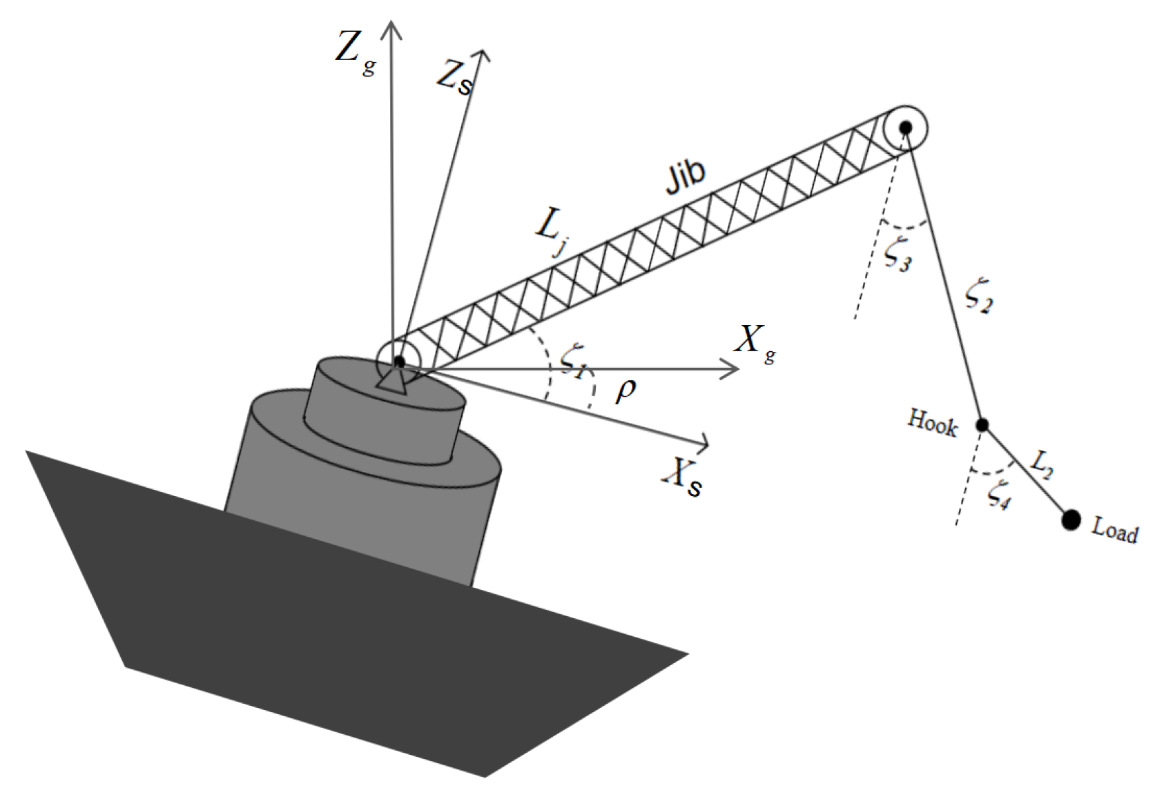
Figure 2.
Flowchart of the overall control system.
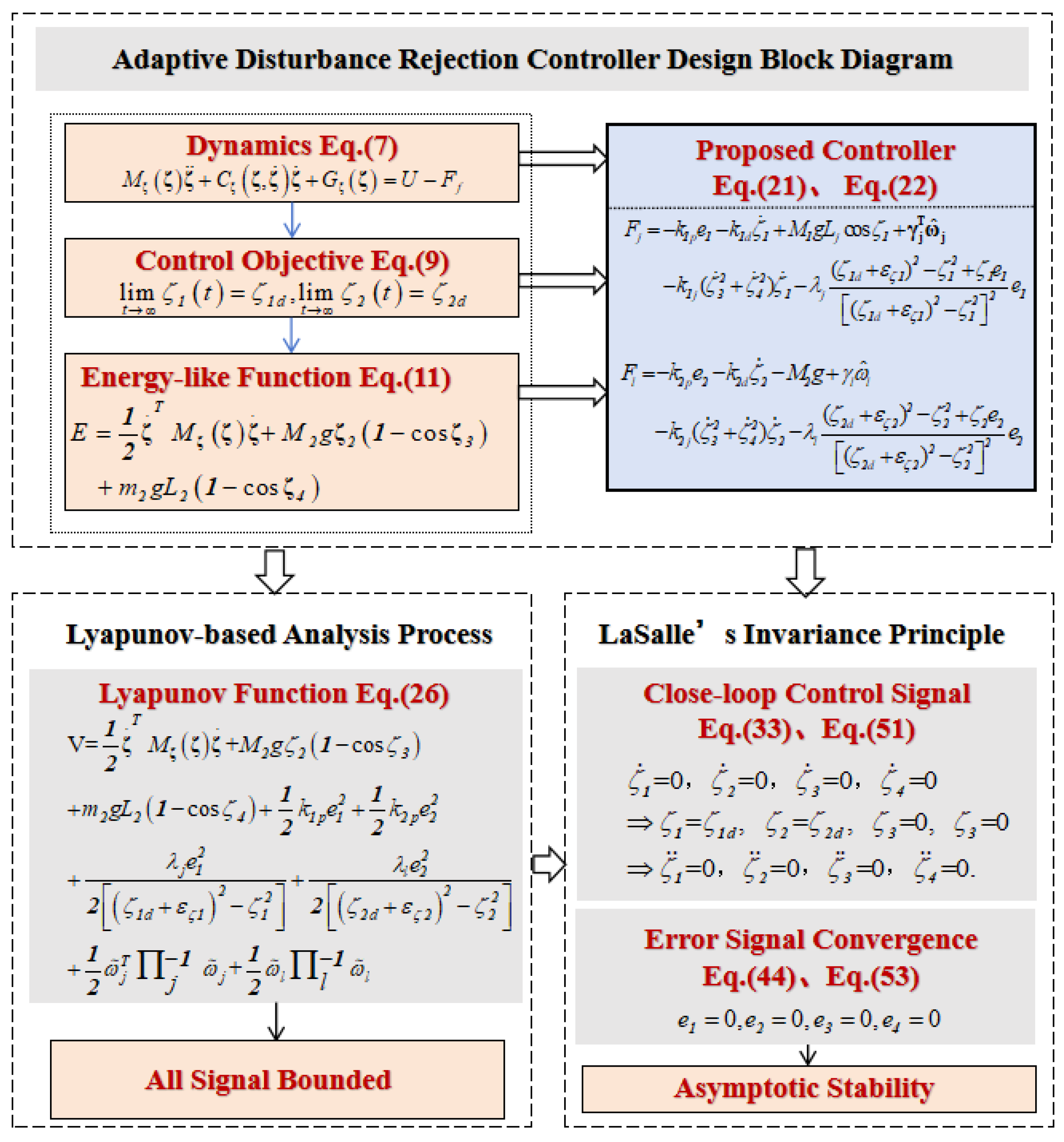
Figure 3.
The results of Group 1 and Group 2. (a) The results of Group 1: comparison simulation with PD controller and the nonlinear controller (blue solid line: the proposed controller; red dotted line: the adaptive controller; green dashed line: the PD controller). (b) The results of Group 2: adding external interference (blue solid line: the proposed controller; red dotted line: the adaptive controller; green dashed line: the PD controller. The interference is added at ).
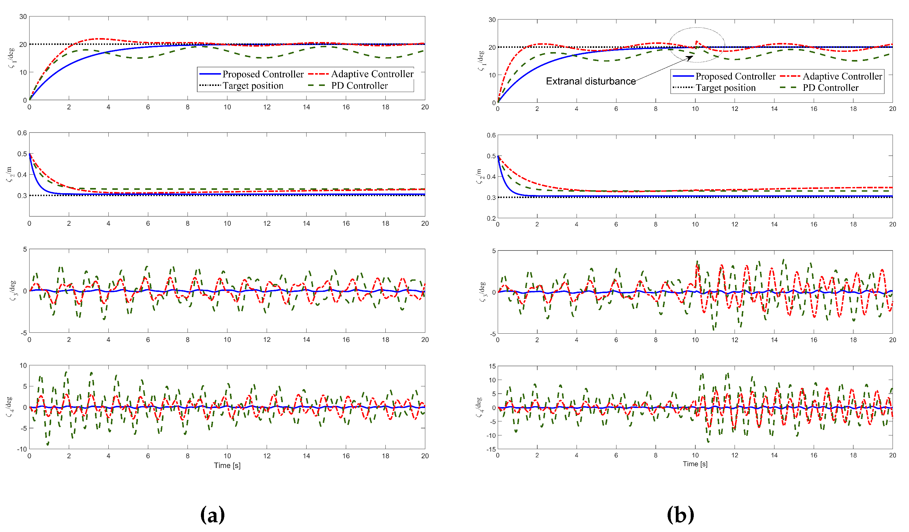
Figure 4.
The results of Group 3 and Group 4. (a) The results of Group 3: increasing the load mass to 1 kg (blue solid line: the proposed controller; red dotted line: the adaptive controller; green dashed line: the PD controller). (b) The results of Group 4: changing the initial and target length of the rope to 0.1 m and 0.4 m, respectively (blue solid line: the proposed controller; red dotted line: the adaptive controller; green dashed line: the PD controller).
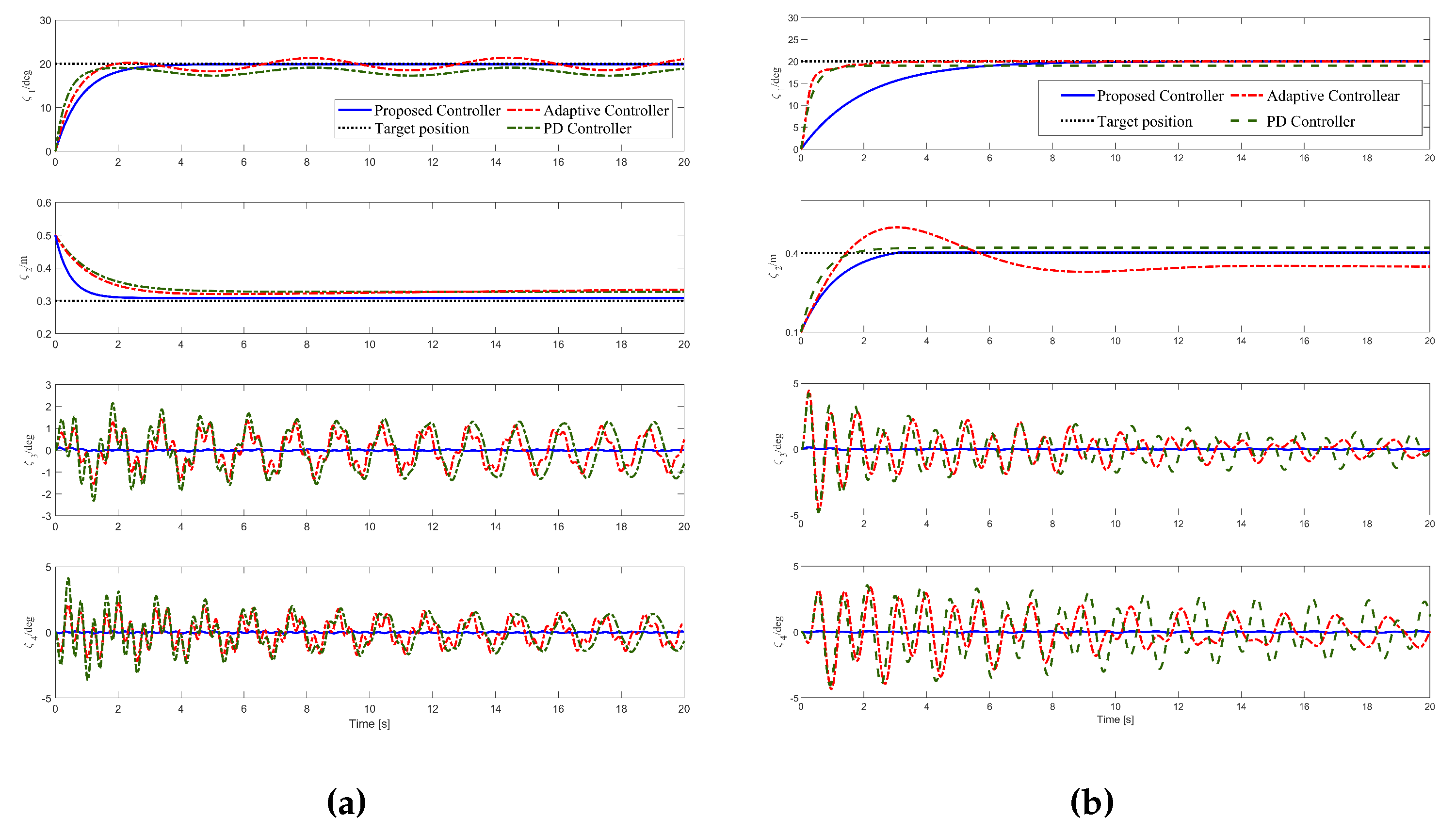
Figure 5.
Self-built double-pendulum crane platform.
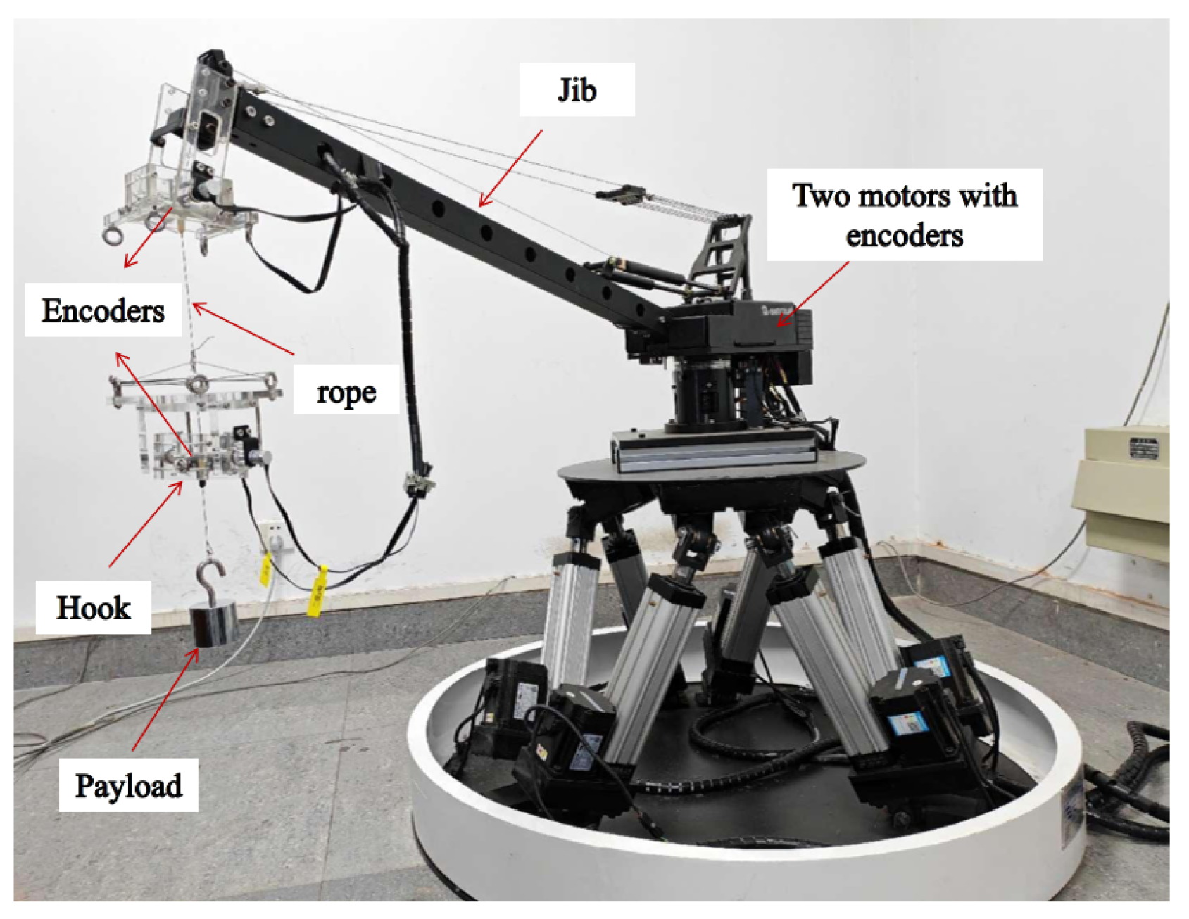
Figure 6.
The comparison between experimental result and simulation result (blue solid line:experimental result; red dotted line: simulation result).
Figure 6.
The comparison between experimental result and simulation result (blue solid line:experimental result; red dotted line: simulation result).
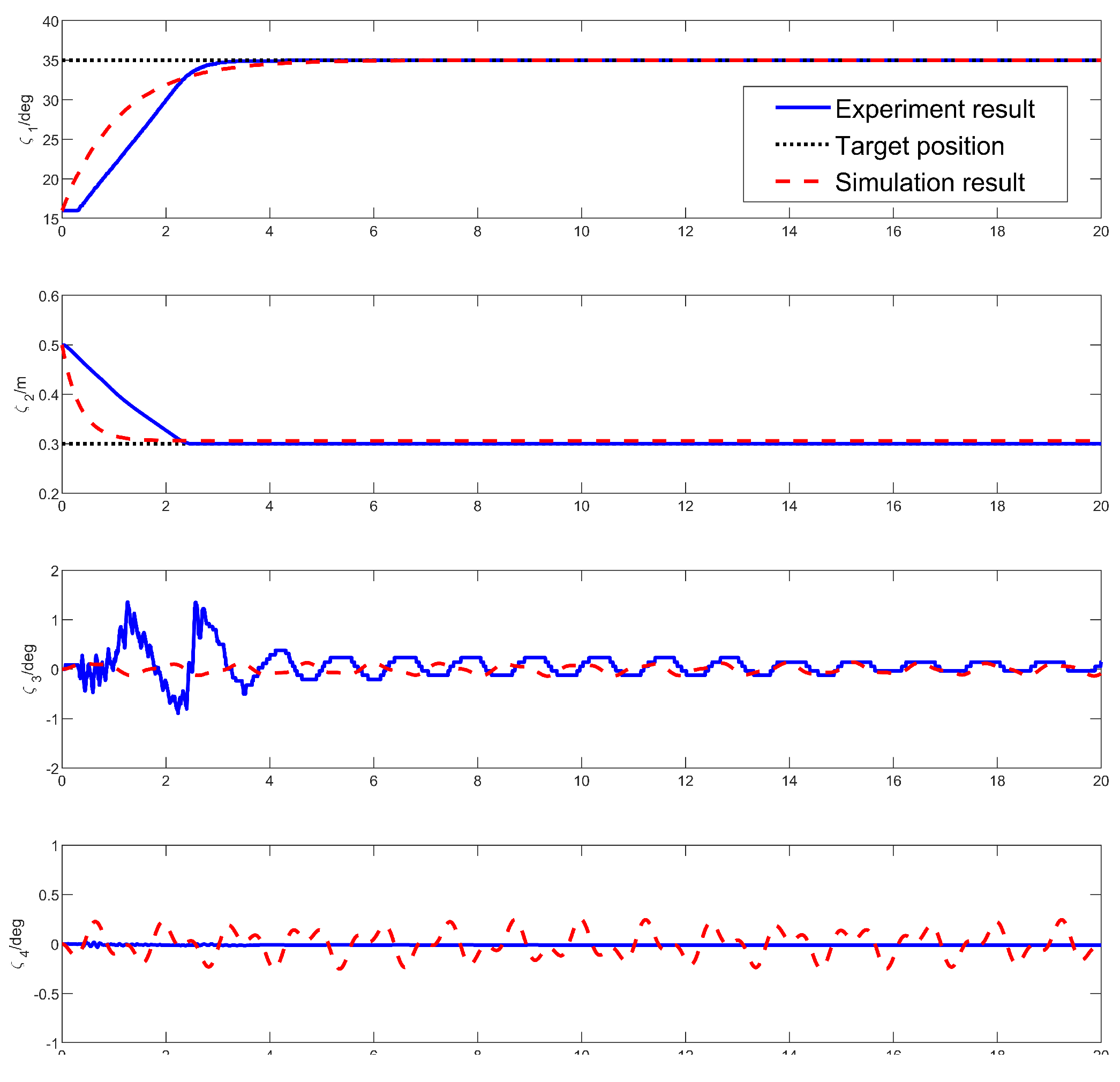

Table 1.
Quantified analysis results.
| Control method | |||
|---|---|---|---|
| Proposed controller | 10.48 | 2.34 | 0 |
| PD controller | / | / | 4.91 |
| Adaptive controller | 9.68 | / | 0.52 |
Disclaimer/Publisher’s Note: The statements, opinions and data contained in all publications are solely those of the individual author(s) and contributor(s) and not of MDPI and/or the editor(s). MDPI and/or the editor(s) disclaim responsibility for any injury to people or property resulting from any ideas, methods, instructions or products referred to in the content. |
© 2024 by the authors. Licensee MDPI, Basel, Switzerland. This article is an open access article distributed under the terms and conditions of the Creative Commons Attribution (CC BY) license (http://creativecommons.org/licenses/by/4.0/).
Copyright: This open access article is published under a Creative Commons CC BY 4.0 license, which permit the free download, distribution, and reuse, provided that the author and preprint are cited in any reuse.


