
Submitted:
11 December 2024
Posted:
12 December 2024
You are already at the latest version
Abstract
Road markings belong to inalienable elements of road infrastructure responsible for increasing traffic safety. They are speciality industrial maintenance coatings that undergo deterioration under usage, which necessitates their renewals to assure preservation of performance parameters. Prior results from a transverse lines field test indicated profound dissimilarities between functional service life that could be achieved with various materials used for road markings. Herein is presented a life cycle assessment based on the results from that study. Global Warming Potential (GWP) resulting from the use of the tested road markings was calculated for a series of renewals to maintain the performance parameters above the required minimum of 1.0 m² of marked surface for 20.0 million vehicle passes. The outcome clearly indicates that the sustainability of road markings is controlled by the functional service life that they provided and not their composition. The calculated total GWP for the series of renewals varied from 15 to 107 kg CO₂ eq., but in most cases was <30 kg CO₂ eq. The choice of materials – both the paints and the glass beads – was shown as playing a pivotal role in the provided functional service life; hence, affecting the GWP. Through furnishing better night time visibility, also road safety was likely positively affected, even though such effects could not be calculated.
Keywords:
glass beads
; life cycle assessment
; carbon footprint
; service life
; road safety
; microplastics
; traffic paint
; retroreflectivity
1. Introduction
A plethora has been written and discussed about sustainability of various products and processes, with cradle-to-grave Life Cycle Assessment (LCA) being used as a tool to quantify the differences [1]. One of the most important weaknesses of LCA is the possibility of changing the outcome depending on setting the system boundaries [2]. However, in most of the cases, one can assume that the process providing the most durable (i.e. long lasting) solution would be associated the lowest long-term use of resources and minimum GWP. A special case are deteriorating systems, where the LCA comprises a series of individual LCAs that are mostly additive [3].
Road markings (RMs) belong to such deteriorating systems. The purpose of their installation and maintenance is channelling and organising traffic, which was reported as leading to increasing road traffic safety. Indeed, it was calculated that the financial expenses associated with the installation and maintenance of RMs were sixtyfold lower than the costs of chaotic traffic and accidents in their absence [4]. The profound importance of RMs as guiderails for drivers cannot be underestimated, as was recently reviewed [5]. RMs are also needed for proper functioning of lane keeping assistance software and other driving automation features [6]. RMs were included only in a very few of LCAs associated with road construction, with details provided even more seldom [7]. In an early LCA of a road in Sweden [8]; the environmental cost of only the application process (the products manufacture and their delivery to the application site were not included) of thick layer thermoplastic RMs was considered. RMs were only briefly mentioned in an assessment of a road construction and maintenance in Denmark [9] and in analysis of the environmental impact of a highway reconstruction in the United States [10]. For evaluations of Spanish road projects, annual renewals of RMs (acrylic paint) were mentioned [11,12], without considering the possibility of obtaining different service life with alternate materials. Analysis done on a construction of a bicycle path in a residential neighbourhood in Belgium considered RMs, with the analysed systems comprised solventborne red paint and thick layer red cold plastic for marking bicycle paths [13]; the frequency of renewals (1 year for paint and 3 years for cold plastic) was noted – overall higher environmental impact of cold plastic was calculated due to much thicker applied layer. From professional perspective the assumed service life of thick layer cold plastic was significantly too short. An LCA done on a renovation of a 22 km section of Panamericana Sur highway in Peru included the installation of RMs [14], but their type was not specified. It was expected that approximately 24% of the total marking volume would be lost every 6 months due to abrasion, which suggests the utilisation of grossly substandard or inappropriately selected materials.
In this paper RMs shall be discussed from the perspective of materials. Because RMs are often regarded as ‘part of the road’, the intricacies associated with the used materials are often ignored, which sometimes lead to misconceptions related to their usage, types, performance requirements and practice, abrasion, and environmental impact [15]. From materials perspective, RMs belong to speciality heavy duty industrial coatings – they are dual layer systems comprising the bottom coating layer and the top retroreflective layer – only their co-operation provides the functional product [16].
Given the ubiquity of RMs, it is quite surprising that detailed data related to LCA and the associated GWP of the materials used for them were not published so far. The prior reports only indicated that the controlling parameter was the service life [17,18], but the LCA indicators were not given. In this work, values of LCA parameters for selected materials used for RMs are published to fill this knowledge gap. Data for several categories of resource uses to calculate GWP for environmental product declarations are provided herein [19]; human toxicity indices [20] were included to account for potential differences associated with the various tested materials. To provide LCA appropriate for the deteriorating systems, functional service life of RMs based on retroreflectivity obtained from field testing [21] was combined with the GWP data for individual applied materials to provide the results for a series of renewals. Calculations were done for 1.0 m² of RMs that would be periodically renewed to maintain functional properties for the exposure to 20.0 million vehicle passes. Several uncertainties and unknowns related to LCAs of RMs are noted amongst research needs. The function of the layers of RMs, the materials used for them, and the distinction between functional and physical service life of RM are described herein as a reference for researchers. The provided outcome would be useful not only for environmental scientists, but also for policymakers and road administrators seeking the optimum solutions to simultaneously maximise visibility of RMs to enhance road safety and minimise negative environmental impacts.
2. Road Markings
2.1. Properties
Because of numerous mistakes related to RMs – both the used materials and service life – that resulted in information chaos and fundamental errors that surfaced particularly in the field related to microplastic emissions [22], properties, materials, and functions of RMs and their layers are summarised in Table 1. The materials for retroreflective layer are dropped-on on the coating layer while it is still in the molten state and become embedded in it – only at that point RMs are formed. Additional materials for both layers are possible, but at present their market penetration is negligible, so they shall not be described herein.
RMs can be classified based on the layer thickness into thin layer and thick layer. The latter may be applied as three-dimensional regular or random structures that (1) provide vibroacoustic effect warning drivers departing the travel lane, (2) facilitate moisture drainage to improve the visibility during rain, and (3) shelter some of the GBs from abrasion to prolong functional service life. According to the standard EN 1436 [23], RMs are classified based on visibility under conditions of wetness into Type I (‘do not necessarily have special properties intended to enhance the retroreflection in wet or rainy conditions’) and Type II (‘with special properties intended to enhance the retroreflection in wet or rainy conditions’). Usually Type II performance can be achieved only with structured applications, but there exist some mixtures of GBs that provide it also in flat lines. The differences between visibility of Type I and Type II are profound [24].
The key functional properties of RMs include [23]:
- Retroreflectivity – the phenomenon of returning the light from vehicle’s headlights back toward the driver, measured as coefficient of retroreflected luminance (RL) and expressed in mcd/m²/lx; RL can be also measured under the conditions of wetness (RW). While RL could be theoretically measured also during rain (RR), such measurements in the field are not being done due to the absence of reliable methodology. Retroreflectivity is obtained due to the GBs and their embedment to circa 50–60% in the coating layer [25,26]. The effect of RL on visibility and contrast of RMs has been analysed [27,28]. Studies of drivers’ visual needs indicated that RL >150 mcd/m²/lx should be maintained at all times [29].
- Skid resistance – measured using British Pendulum skid resistance tester (SRT) and expressed in unitless Pendulum Test Value (PTV). Skid resistance is furnished by the retroreflective layer (in RMs applied in thick layers also by the coarse fillers in the coating layer).
Of critical importance is recognition of the difference between functional and physical service life of RMs:
- Functional service life – RMs meet or exceed the functional properties demanded in specifications, particularly RL, Qd, and skid resistance.
- Physical service life – RMs no longer meet the demanded functional properties but remain on the road surface.
- End-of-life – RMs are physically eroded (i.e. completely abraded) and cease being visible for road users.
Because tyres of all vehicles encroaching on RMs are rolling on the GBs (during the period of functional service life, tyres have no contact with the coating layer – the spacing between the GBs are approximately 10× smaller than the tyre tread), they can become scratched or extracted from the coating layer; hence, it is the RL that in vast majority of cases fails first. Consequently, the key consideration is the connection between the functional service life and retroreflectivity. Usually, minimum RL >200–300 mcd/m²/lx is demanded from freshly applied RM. Upon wear and tear, RL decreases until a threshold level is reached (in Europe, typically 100 mcd/m²/lx); since only the GBs are capable of providing RL, they must be present until that moment and even later. At that point, the RMs should be renewed with another layers of materials; hence, layer stacking occurs [15]. In quite rare circumstances, layer stacking may result in excessive thickness; usually upon exceeding 6 mm, RMs would be mechanically removed (if done properly, without generating dust) and the residue disposed properly [32]. One must keep in mind that before RMs are permitted to be used on roads, they are tested for suitability and performance either under laboratory conditions [33] or in the field [34,35]; all of the functional properties must meet the established minima throughout the designed functional service life, for which the materials are homologated [36].
2.2. Materials for Road Markings
Basic ingredients for the coating layer of RMs – binders, fillers, pigments, and additives – are similar to any other coatings and do not demand separate discussion. However, in some cases also coarse fillers (mostly minerals like sand, corundum, flintstone, and other), with diameters up to circa 1.0 mm are being used to enhance the properties. In addition, the same GBs that are used for the retroreflective layer may also be intermixed with the coating layer (so-called ‘premix’ GB), where they play the role of a coarse filler (in cold plastic) and/or deliver RL (in thermoplastic). Amongst pigments, the most important is titanium dioxide (TiO₂) as it provides the white colour that is most easily perceived due to furnishing excellent contrast apparent against dark roadway surface ; it cannot be effectively replaced [37]. It is an inimitable pigment for RMs also because of high refractive index (RI), which for the rutile polymorph that is used in RMs reaches 2.6 – it provides surface for RL. Because TiO₂ has relatively high carbon footprint [38],the minimisation of its content may be desired. Nano-sized TiO₂ is not being used in RMs, partially because the sub-micron particles do not seem to be able to form appropriate diffusion cone for RL. Amongst other colours, yellow is most commonly used; even though lead chromate was replaced in RMs many years ago with benign yellow organic pigments [39], residual local contamination is being sometimes reported. Typical materials for the coating layer of RMs are described in Table 2.
Concise description of materials used for the retroreflective layer is furnished in Table 3 (GBs, with colloquial subjective nomenclature) and in Table 4 (ASPs). Typical requirements for them are described in the standard EN 1423 [44]. It is noteworthy that laboratory analysis of numerous types of GBs from various sources worldwide revealed them to be solely amorphous materials, devoid of contamination by crystalline silica or toxic metals and metalloids [45]; the absence of harmful ingredients was also confirmed based on samples collected in the field in many European countries [46]. Various types of GBs can be intermixed with each other; they are often intermixed with the ASPs that comprise 20–35% of the retroreflective layer. At the production stage, the retroreflective layer materials are coated with an organosilane to assure adhesion to the coating layer materials; the choice of organosilane depends on the target matrix [47].
3. Materials and Methods
3.1. LCA Assumptions
In the presented LCA the following stages were considered:
- Production, including (a) preparation of the raw materials, including their mining and/or production, (b) transport of the raw materials to the manufacture site, and (c) manufacturing process itself, including packaging. The manufacture location for the retroreflective layer components was chosen Amstetten (Austria) and for the coating layer Frankfurt am Main (Germany); choice of these locations affected the environmental costs of transportation and energy.
- Installation, including transport from the manufacturing sites and the energy used for installation. As installation location was chosen Regensburg (Germany) as being roughly mid-point between the manufacturing sites.
- Waste disposal of the packaging and residual materials during production and application.
- The following were disregarded (assumed nil values):
- The use stage – does not apply because RMs are passive products.
- Reuse, recovery, recycling – omitted because RMs usually do not undergo such processes. However, one should observe that during road surface renovation, the RMs are typically reused or recycled together with the asphalt or concrete. Furthermore, during realignment of the road delineation or when the layer thickness of the RMs becomes excessive due to stacking [32], they may be mechanically removed and disposed (there might be possibility of recycling).
3.2. Materials
For proper LCA analysis, one must know the composition of the materials. In case of those used for RM, it is quite difficult because of significant proprietary knowledge and difficulties in separating of the mixtures into individual ingredients. The composition of materials for RMs that were subjected to this assessment, idealised per professional knowledge and limited resources that included publicly available exemplary formulations, safety data sheets, etc. is provided in Table 5 (coating layer materials [21]) and in Table 6 (retroreflective layer materials [45,52]). Other materials that were described above in Table 2 and Table 4 are omitted because they were not analysed within this effort.
3.3. Carbon Footprint Components
In Table 7 are provided the individual LCA. Data, obtained from publicly available databases and supplemented with professional knowledge related to the processes, is given for preparation of 1.0 kg of each material and includes in all of the cases the energy for manufacturing and the environmental cost of packaging. Due to updates of databases and possible changes to energy supplies, possible modified approaches associated with the materials’ production, and with calculating methodology, the provided values cannot be considered as unchangeable [54]. Provided calculations are based on data from publicly available databases available for 2022 and were supplemented by professional knowledge related to the used processes; the chosen production locations and processes used at those plants affected the provided values. Whereas there are additional LCA impact categories, they were omitted from Table 7 because the values were <0.01 for each of the evaluated materials.
3.4. Service Life of Road Markings
A plethora of models of degradation of RL were presented – from simple to excessively complex [55,56,57]. In majority of them, the length of service life of RMs is expressed in time scale. While it may be appropriate in some cases – particularly when the applied RMs are destroyed by snow ploughs and need to be renewed annually – in other situations the functional service life is clearly correlated with traffic load; other impactors play minor role. Our research indicated that the use of weight adjustment of the passing vehicles leads to better correlation between dissimilar traffic types; such adjustment is also prescribed in Austrian standard ONR 22440-1 [34].
Our earlier field and laboratory studies indicated profound dissimilarities in functional service life that could be achieved with various types of RMs. The most extensive testing was done on thin layer materials applied as transverse lines in Croatia [21]; this data set from side-by-side comparison shall be examined herein. One must keep in mind that all of the presented functional service life data is burdened with uncertainties, which are natural in case of RMs under usage.
4. Results
Based on data and assumptions provided above, including the functional service life measured during field testing [21], total GWP per 1.0 m² of marked surface was calculated for the initial usage and for the renewals to maintain these RMs above RL 150 mcd/m²/lx for 20.0 million weight-adjusted vehicle passes. Included were values from Table 7, environmental impacts of transportation to the chosen exemplary application site, and the application itself. Assumed were typical materials spreading rates: solventborne and waterborne paints 0.6 kg/m², sprayed cold plastic 0.5 kg/m² (lower spreading rate than in cases of paints to account for the solvent evaporation; hence, similar dry layer thicknesses were examined), and drop-on retroreflective layer materials 0.4 kg/m². The results are given in Table 8 and charted in Figure 1; note some inconsistences due to rounding for the clarity of data presentation. This outcome concurs with our prior rough assessment based on materials consumption [21]. Also, it confirms the results published elsewhere [17,18,58].
5. Discussion
The obtained results indicate that GWP of all tested applied RMs was similar: approximately 3.0 ±0.2 kg CO₂ eq./m² were required. The real differences emerged only after considering the series of renewals; the following ranges could be perceived:
- Very high GWP – >100 kg CO₂ eq./m² in case of the low-end paint. This should be considered as grossly irregular but is highly probable. The unexpected very low performance prompted repeat field test, where essentially the same results were measured [58]. It may be hypothesised that the absence of toluene, an excellent solvent for RMs that facilitates the adhesion to asphalt surface [59], could be playing a role. This underlines the necessity of proper field testing, as the paint was homologated at the roundtable for the use in Germany [33].
- Medium GWP – 30–45 kg CO₂ eq./m² in cases of the typical quick-dry waterborne paint and sprayed cold plastic, both reflectorised with the ‘Standard’ GBs.
- Low GWP – 20–30 kg CO₂ eq./m² in majority of cases.
- Minimal GWP – <20 kg CO₂ eq./m², in cases of sprayed cold plastic and high-performance waterborne paint, both reflectorised with the inclusion of ‘Premium’ GBs. One should observe that the use of ‘Premium’ GBs, with RI 1.6–1.7, despite environmental expense of production much higher than in case of ‘Standard’ GBs, did not cause the increase in long-term GWP – contrariwise. Even though the reported RL rate of decay with such GBs was higher than in case of the ‘Standard’ GBs [21], the much higher initial RL still permitted for the obtention of prolonged functional service life, which lowered the long-term environmental burden.
There are several uncertainties and weaknesses of this study that must be acknowledged; they originate either from inherent inadequacies of the utilised LCA protocols, from the absence of data, and from the selection of data sources:
- The analysis was done based on ‘cradle-to-end of functional service life’ and not ‘cradle-to-grave’. The data for the physical service life and end-of-life stages is not available; this remains amongst major research needs.
- Exclusion of the typical peroxide initiator, necessary for formation of cold plastic RMs has to be noted as it could potentially affect the outcome. Since LCA data for such material was not available, its carbon footprint was but omitted.
- In all of the analysed cases, it was assumed that renewal would occur immediately when RL <150 mcd/m²/lx was measured. In practice, even in the mild climate in Croatia, there are no road marking activities during winter. Hence, in practice, renewals could be delayed until spring when RL <150 mcd/m²/lx would be measured.
- The selection of manufacture and application locations, along with the local requirements related to materials composition, did affect the outcome of the LCA.
- The chosen materials, even though purchased commercially from several manufacturers, do not represent the full spectrum of available products. In addition, some uncertainties related to the composition remain.
- The absence of comparable data for thick layer RMs was the reason for their exclusion from analysis. Materials like thermoplastic (designed for slow wear-off to continuously furnish RL), cold plastic (capable of furnishing exquisite physical service life), and structured cold plastic (furnishing extended functional service life and improved visibility under wet conditions) ought to be tested.
- This analysis was based on RL under dry conditions and the most-used regions of transverse lines. Similar evaluation based on RW should be performed. Such testing would reveal any possible differences due to dissimilar materials that can provide retroreflectivity under wet conditions. Structured thick layer RMs and tapes should also be included because of their design as Type II RMs.
- Evaluation based on the least-used regions of the transverse lines should be done; major differences in performance, not paralleling the tested most-used regions, were measured [21].
- Physical service life of various RMs was not included. At the test field, a low-end waterborne paint (excluded from this analysis) failed completely [21] – it underwent erosion during winter exposure even in the absence of meaningful snow ploughing.
- The LCA data was calculated for manufacture at modern production facilities in Europe. Large variations are expected for other locations – due to the physical location and the associated transport expenses, due to the used energy and the emissions, and due to the local production processes. The same applies to the application location.
- Obstruction of traffic due to road marking activities was not included, even though – through increased emissions from queueing up vehicles – it may affect the results. Only one brief report on this topic was found in the available literature [61]. This corollary aspect remains excluded from the LCA.
- The physical service life (during which abrasion is likely to occur) and the end-of-life considerations were not included. The fate of particles generated from abrasion of RMs remains unknown; while generally they ought to be free from toxic ingredients (like in all of the cases presented herein), in some formulations that are nowadays obsolete and generally banned in Europe, harmful ingredients and pigments were present. It is of utmost importance to carefully assess all possible contamination or toxic effects and separate the current issues from erstwhile.
- The topic of microplastic emissions from RMs, which recently gained scientific attention [15,22], was not addressed in this LCA. The methodology for such inclusion is still being developed [62,63,64]. Nonetheless, one should keep in mind that the emissions of microplastics from RMs occur only after the functional service life is exhausted [15,22] (the exception are thermoplastic RMs due to their design for wear-off), which did not occur in any of the examples presented herein.
- Road safety – the main purpose of installation of RMs – was not included. At present, there is no reliable method for calculating this impact on LCA. The presence of RMs was consistently reported as lowering the number and severity of accidents [4,65]. Also, the increase in RL was positively correlated with the decrease in single vehicle crashes at night [66,67].
Even though carbon footprint of RMs is not included in public tenders so far, there are a few examples where it was at least considered [68,69,70]. Based on the results provided herein, the sustainable choice should always be the materials that provide the longest functional service life.
One should keep in mind the ultimate purpose of installation and maintenance of RMs – the increase in road safety that they provide. While quantification of such effects in this LCA was not done, it belongs to significant research needs. Unfortunately, no suitable reliable methodology exists and data is too scarce for any reliability. For a fair comparison with the outcome of the calculations presented herein, representative thick layer materials should be evaluated in the transverse arrangement; also, representative RMs ought to be assessed when applied as longitudinal lines at various roads and in dissimilar climates. Evaluation of RMs subjected to the action of winter maintenance, with special attention to the effects of studded tyres that disturb the coating layer integrity [71], should be done. Related to this would be a study of rosin-based, hydrocarbon-based, and hybrid thermoplastics, such as those commonly used in the Nordic countries where the use of studded tyres is permitted [72]. The emerging concept of using luminescent RMs also ought to be addressed; while publications on this topic recently became plentiful with most researchers claiming advantages in comparison with the traditional technologies [73], the environmental aspects of using a pigment containing rare earth elements were not addressed so far.
6. Conclusions
Cradle-to-gate LCA done on materials used as thin layer RMs revealed that the lowest overall carbon footprint can be achieved when the longest functional service life is achieved; the initial composition did not play any meaningful role. Hence, for the nth time, it was shown that durability leads to sustainability. In the given examples, the total long-term GWP varied from 15 to 107 kg CO₂ eq. per 1.0 m² of marked surface, with majority of the evaluated systems having GWP <30 kg CO₂ eq./m². Meaningfully higher initial GWP of sprayed cold plastic and of GBs with RI 1.6–1.7 was offset through the prolonged functional service life that they afforded, in some cases leading to the smallest long-term environmental impact. This LCA encompassed only thin layer RMs and their evaluation at transverse lines; similar analyses of thick layer RMs are due. The main purpose of installation and maintenance of RMs – increase in road traffic safety – remains unquantified.
Author Contributions
Conceptualisation, T.B.; methodology, T.B.; software, T.B. and F.W.; validation, T.B. and F.W.; formal analysis, T.B. and F.W.; investigation, F.W.; resources, F.W.; data curation, T.B. and F.W.; writing—original draft preparation, T.B.; writing—review and editing, T.B. and F.W.; visualization, T.B.; supervision, T.B. and F.W.; project administration, F.W.; funding acquisition, F.W. Both authors have read and agreed to the published version of the manuscript.
Funding
This research received no external funding.
Institutional Review Board Statement
Not applicable.
Informed Consent Statement
Not applicable.
Data Availability Statement
Selected data is available on reasonable request, with some details being proprietary and confidential.
Conflicts of Interest
The authors are employed by a company involved in manufacture and application of RMs. Their employer had no role in the design of this study; in the collection, analyses, or interpretation of data; in the writing of the manuscript; or in the decision to publish the results.
References
- Sonnemann, G.; Margni, M. (eds), Life cycle management. SpringerOpen, 2015. [CrossRef]
- Tillman, A.M.; Ekvall, T.; Baumann, H.; Rydberg, T. Choice of system boundaries in life cycle assessment. J. Cleaner Prod. 1994, 2(1), 21-29. [CrossRef]
- Sánchez-Silva, M.; Klutke, G.A. (eds), Reliability and life-cycle analysis of deteriorating systems. Springer International Publishing: Cham, Switzerland, 2016. [CrossRef]
- Miller, T.R. Benefit–cost analysis of lane marking. Transport. Res. Record 1992, 1334, 38–45.
- Babić, D.; Fiolić, M.; Babić, D.; Gates, T. Road markings and their impact on driver behaviour and road safety: a systematic review of current findings. J. Adv. Transport. 2020, 7843743. [CrossRef]
- Storsæter, A.D.; Pitera, K.; McCormack, E.D. The automated driver as a new road user. Transport Reviews 2020, 41(5), 533–555. [CrossRef]
- Aryan, Y.; Dikshit, A.K.; Shinde, A.M. A critical review of the life cycle assessment studies on road pavements and road infrastructures. J. Environ. Manag. 2023, 336, 117697. [CrossRef]
- Stripple, H. Life cycle assessment of road: a pilot study for inventory analysis. IVL Rapport B 1210 E. IVL Swedish Environmental Research Institute: Göteborg, Sweden, 2001.
- Birgisdóttir, H.; Pihl, K.A.; Bhander, G.; Hauschild, M.Z.; Christensen, T.H. Environmental assessment of roads constructed with and without bottom ash from municipal solid waste incineration. Transport. Res. Part D, Transp. Environ. 2006, 11(5), 358–368. [CrossRef]
- Noland, R.B.; Hanson, C. S. Life-cycle greenhouse gas emissions associated with a highway reconstruction: a New Jersey case study. J. Cleaner Prod. 2015, 107, 731–740. [CrossRef]
- Barandica, J.M.; Fernández-Sánchez, G.; Berzosa, Á.; Delgado, J.A.; Acosta, F.J. Applying life cycle thinking to reduce greenhouse gas emissions from road projects. J. Cleaner Prod. 2013, 57, 79–91. [CrossRef]
- Fernández-Sánchez, G.; Berzosa, Á.; Barandica, J.M.; Cornejo, E.; Serrano, J.M. Opportunities for GHG emissions reduction in road projects: a comparative evaluation of emissions scenarios using CO₂NSTRUCT. J. Cleaner Prod. 2015, 104, 156–167. [CrossRef]
- Trigaux, D.; Wijnants, L.; De Troyer, F.; Allacker, K. Life cycle assessment and life cycle costing of road infrastructure in residential neighbourhoods. Int. J. Life Cycle Assessm. 2017, 22, 938–951. [CrossRef]
- Verán-Leigh, D.; Larrea-Gallegos, G.; Vázquez-Rowe, I. Environmental impacts of a highly congested section of the Pan-American highway in Peru using life cycle assessment. Int. J. Life Cycle Assessm. 2019, 24, 1496–1514. [CrossRef]
- Burghardt, T.E.; Pashkevich, A.; Babić, D.; Mosböck, H.; Babić, D.; Żakowska, L. Microplastics and road markings: the role of glass beads and loss estimation. Transport. Res. Part D, Transp. Envir. 2022, 102, 103123. [CrossRef]
- Pocock, B.W.; Rhodes, C.C. Principles of glass-bead reflectorization. Highway Res. Board Bull. 1952, 57, 32–48.
- Cruz, M.; Klein, A.; Steiner, V. Sustainability assessment of road marking systems. Transport. Res. Procedia 2016, 14, 869–875. [CrossRef]
- Burghardt, T.E.; Pashkevich, A.; Żakowska, L. Influence of volatile organic compounds emissions from road marking paints on ground-level ozone formation: case study of Kraków, Poland. Transport. Res. Procedia 2016, 14, 714–723. [CrossRef]
- Achenbach, H.; Diederichs, S.K.; Wenker, J.L.; Rüter, S. Environmental product declarations in accordance with EN 15804 and EN 16485—how to account for primary energy of secondary resources?. Environ. Impact Assessm. Rev. 2016, 60, 134–138. [CrossRef]
- Hertwich, E.G.; Mateles, S.F.; Pease, W.S.; McKone, T.E. Human toxicity potentials for life-cycle assessment and toxics release inventory risk screening. Environ. Toxicol. Chem. Int. J. 2001, 20(4), 928–939. [CrossRef]
- Burghardt, T.E.; Babić, D.; Pashkevich, A. Sustainability of thin layer road markings based on their service life. Transport. Res. Part D, Transp. Envir. 2022, 109, 103339. [CrossRef]
- Burghardt, T.E.; Pashkevich, A. Road markings and microplastics – a critical literature review. Transport. Res Part D, Transp. Envir. 2023, 119, 103740. [CrossRef]
- European Standard EN 1436. Road marking materials — Road marking performance for road users and test methods. European Committee for Standardization: Brussels, Belgium, 2018.
- Burghardt, T.E.; Chistov, O.; Reiter, T.; Popp, R.; Helmreich, B.; Wiesinger, F. Visibility of flat line and structured road markings for machine vision. Case Studies Constr. Mat. 2023, 18, e02048. [CrossRef]
- Vedam, K.; Stoudt, M.D. Retroreflection from spherical glass beads in highway pavement markings. 2: Diffuse reflection (a first approximation calculation). Appl. Optics 1978, 17(12), 1859–1869. [CrossRef]
- Grosges, T. Retro-reflection of glass beads for traffic road stripe paints. Optical Mat. 2008, 30, 1549–1554. [CrossRef]
- Spieringhs, R.M.; Smet, K.; Heynderickx, I.; Hanselaer, P. Road marking contrast threshold revisited. Leukos 2022, 18(4), 493–512. [CrossRef]
- Guan, Y.; Hu, J.; Wang, R.; Cao, Q.; Xie, F. Research on the nighttime visibility of white pavement markings. Heliyon 2024, 10, e36533. [CrossRef]
- Lee, H.-S.; Oh, H.-U. Minimum Retroreflectivity for Pavement Markings by Driver's Static Test Response. J. Eastern Asia Soc. Transport. Studies 2005, 6, 1089–1099. [CrossRef]
- COST 331 – requirements for horizontal road marking. European Commission. Directorate General Transport. Luxembourg: Office for Official Publications of the European Communities, 1999.
- Brémond R. Visual performance models in road lighting: a historical perspective. Leukos 2020, 17, 212–241. [CrossRef]
- Technical Report CEN/TR 16958. Road marking materials. Conditions for removing/masking road markings. European Committee for Standardization: Brussels, Belgium, 2017.
- Keppler, R. 15 Jahre Eignungsprüfungen von Markierungssystemen auf der Rundlaufprüfanlage der Bundesanstalt für Straßenwesen [in German]. Straßenverkehrstechnik 2005, 49(11), 575–582.
- ONR 22440-1. Bodenmarkierungen. Funktionsdauer – Teil 1: Allgemeines. Ortsgebiet [in German]. Österreichisches Normungsinstitut: Wien, Austria, 2018.
- ONR 22440-2: Bodenmarkierungen. Funktionsdauer – Teil 2: Ortsgebiet [in German]. Österreichisches Normungsinstitut: Wien, Austria, 2018.
- Zusätzlichen Technischen Vertragsbedingungen und Richtlinien für Markierungen auf Straßen (ZTV-M); 2013. Serie: FGSV, Nr. 341 [in German]. FGSV Verlag: Köln, Germany, 2013.
- de Jong, H.; Flapper, J. Titanium dioxide: ruling opacity out of existence? Eur. Coatings J. 2017, 10, 52–55.
- Hassan M. Life-cycle assessment of titanium dioxide coatings. In: Construction Research Congress 2009; Seattle, WA, USA, 5-7 April 2009, pp. 836–845. [CrossRef]
- Stratmann, H.; Hellmund, M.; Veith, U.; End, N.; Teubner, W. Indicators for lack of systemic availability of organic pigments. Regul. Toxicol. Pharmacol. 2020, 115, 104719. [CrossRef]
- Burghardt, T.E.; Pashkevich, A. Emissions of volatile organic compounds from road marking paints. Atmos. Environ. 2018, 193, 153–157. [CrossRef]
- van der Kooij, H.M.; Sprakel, J. Watching paint dry; more exciting than it seems. Soft Matter 2015, 11(32), 6353–6359. [CrossRef]
- Kugler, S.; Ossowicz, P.; Malarczyk-Matusiak, K.; Wierzbicka, E. Advances in rosin-based chemicals: the latest recipes, applications and future trends. Molecules 2019, 24(9), 1651. [CrossRef]
- Cashman, S.A.; Moran, K.M.; Gaglione, A.G. Greenhouse gas and energy life cycle assessment of pine chemicals derived from crude tall oil and their substitutes. J. Ind. Ecol. 2016, 20(5), 1108−1121. [CrossRef]
- 44. Deutsche Norm DIN EN 1423. Straßenmarkierungsmaterialien - Nachstreumittel - Markierungs-Glasperlen, Griffigkeitsmittel und Nachstreugemische [in German]. DIN Deutsches Institut für Normung: Berlin, Germany, 2012.
- Burghardt, T.E.; Ettinger, K.; Köck, B.; Hauzenberger, C. Glass beads for road markings and other industrial usage: crystallinity and hazardous elements. Case Studies Constr. Mat. 2022, 17, e01213. [CrossRef]
- Migaszewski, Z.M.; Gałuszka, A.; Dołęgowska, S.; Michalik, A. Glass microspheres in road dust of the city of Kielce (south-central Poland) as markers of traffic-related pollution. J. Hazard. Mat. 2021, 413, 125355. [CrossRef]
- Plueddemann, E.P. Adhesion through silane coupling agents. J. Adhesion 1970, 2(3), 184–201. [CrossRef]
- Pike, A.M.; Datta S. Effect of glass bead refractive index on pavement marking retroreflectivity considering passenger vehicle and airplane geometries. Transport. Res. Record 2020, 2674(10), 438–447. [CrossRef]
- Wan, Z.; Wang, H. Retroreflectivity-based service life and life-cycle cost analysis of airfield pavement markings. Transport. Res. Record 2024, 03611981241255368. [CrossRef]
- Burns, D.; Hedblom, T.; Miller, T. Modern pavement marking systems: relationship between optics and nighttime visibility. Transport. Res. Record 2007, 2056, 43–51. [CrossRef]
- Shin, S.Y.; Lee, J.I.; Chung, W.J.; Choi, Y.G. Correlations between refractive index and retroreflectance of glass beads for use in road-marking applications under wet conditions. Curr. Optics Photonics 2019, 3(5), 423-428. [CrossRef]
- Burghardt, T.E.; Köck, B.; Pashkevich, A. Fasching, A. Skid resistance of road markings: literature review and field test results. Roads Bridges 2023, 22, 141–164. [CrossRef]
- Siwińska-Stefańska, K.; Krysztafkiewicz, A.; Jesionowski, T. Effect of inorganic oxides treatment on the titanium dioxide surface properties. Physicochem. Problems Mineral Process. 2008, 42, 141-–152.
- Konradsen, F.; Hansen, K.S.H.; Ghose, A.; Pizzol, M. Same product, different score: how methodological differences affect EPD results. Int. J. Life Cycle Assessm. 2024, 29(2), 291–307. [CrossRef]
- Babić, D.; Ščukanec, A.; Babić, D.; Fiolić, M. Model for predicting road markings service life. Baltic J. Road Bridge Eng. 2019, 14(3), 341–359. [CrossRef]
- Karimzadeh, A.; Shoghli, O. Predictive analytics for roadway maintenance: a review of current models, challenges, and opportunities. Civil Eng. J. 2020, 6, 602–625. [CrossRef]
- Idris, I.I.; Mousa, M.; Hassan, M. Modeling retroreflectivity degradation of pavement markings across the US with advanced machine learning algorithms. J. Infrastr. Preserv. Resilience 2024, 5, 3. [CrossRef]
- Burghardt, T.E.; Pashkevich, A. Green Public Procurement criteria for road marking materials from insiders’ perspective. J. Cleaner Prod. 2021, 298, 126521. [CrossRef]
- Burghardt, T.E.; Pashkevich, A.; Żakowska, L. Contribution of solvents from road marking paints to tropospheric ozone formation. Budownictwo Architektura 2016, 15(1), 7–18. [CrossRef]
- Mitrović, A.; Ščukanec, A.; Babić, D. Impact of winter maintenance on retroreflection of road markings. In: Proceedings of International Scientific Conference “Perspectives on Croatian 3PL Industry in Acquiring International Cargo Flows”, Zagreb, Croatia, 12 April 2016, pp. 119–127.
- Fiolić, M.; Habuzin, I.; Dijanić, H.; Sokol, H. The influence of drying of the road marking materials on traffic during the application of markings. In: Proceedings of ZIRP-LST Conference, Opatija, Croatia, 1–2 June 2017, pp. 109–118.
- Vega, G.C.; Gross, A.; Birkved, M. The impacts of plastic products on air pollution-a simulation study for advanced life cycle inventories of plastics covering secondary microplastic production. Sust. Prod. Consumpt. 2021, 28, 848–865. [CrossRef]
- Saling, P.; Gyuzeleva, L.; Wittstock, K.; Wessolowski, V.; Griesshammer, R. Life cycle impact assessment of microplastics as one component of marine plastic debris. Int. J. Life Cycle Assessm. 2020, 25, 2008–2026. [CrossRef]
- Schwarz, A.E.; Herlaar, S.; Cohen, Q.M.; Quik, J.T.K.; Golkaram, M.; Urbanus, J.H., van Emmerik, T.H.M.; Huijbregts, M.A.J. Microplastic aquatic impacts included in life cycle assessment. Resources Conserv. Recycling 2024, 209, 107787. [CrossRef]
- Tsyganov, A.R.; Machemehl, R.B.; Warrenchuk, N.M., Wang, Y. Before-after comparison of edgeline effects on rural two-lane highways. Report No. FHWA/TX-07/0-5090-2. Texas Department of Transportation, Research and Technology Implementation Office: Austin, TX, USA, 2006.
- Avelar, R.E.; Carlson, P. J. Link between pavement marking retroreflectivity and night crashes on Michigan two-lane highways. Transport. Res. Record 2014, 2404, 59–67. [CrossRef]
- Carlson, P.J.; Avelar, R.E.; Park, E.S.; Kang, D.H. Nighttime safety and pavement marking retroreflectivity on two-lane highways: revisited with North Carolina data. In: Proceedings of Transportation Research Board 94th Annual Meeting, Washington, DC, USA, 11–15 January 2015, paper 15-5753.
- Faith-Ell, C.; Balfors, B.; Folkeson, L.The application of environmental requirements in Swedish road maintenance contracts. J. Cleaner Prod. 2006, 14(2), 163–171. [CrossRef]
- Parikka-Alhola, K.; Nissinen, A.. Enhancing green practice in public road construction procurement. In: Proceedings of 3rd International Public Procurement Conference; Amsterdam, The Netherlands, 28–30 August 2008, pp. 655–666.
- Anthonissen, J.; Van Troyen, D.; Braet, J. Using carbon dioxide emissions as a criterion to award road construction projects: a pilot case in Flanders. J. Cleaner Prod. 2015, 102, 96–102. [CrossRef]
- Laurinavičius, A.; Skerys, K.; Jasiūnienė, V.; Pakalnis, A.; Starevičius, M. Analysis and evaluation of the effect of studded tyres on road pavement and environment (I). Baltic J. Road Bridge Eng. 2009, 4(3), 115–122. [CrossRef]
- Lundberg, J.; Janhäll, S.; Gustafsson, M.; Erlingsson, S. Calibration of the Swedish studded tyre abrasion wear prediction model with implication for the NORTRIP road dust emission model. Int. J. Pavement Eng. 2021, 22(4), 432–446. [CrossRef]
- Lin, H.; Chen, F.; Zhang, H. Active luminous road markings: a comprehensive review of technologies, materials, and challenges. Constr. Building Mat. 2023, 363, 129811. [CrossRef]
Figure 1.
Total GWP associated with the analysed RMs, one-time application and a series of renewals to maintain RL >150 mcd/m²/lx for 20.0 million weight-adjusted vehicle passes per lane (transverse lines).
Figure 1.
Total GWP associated with the analysed RMs, one-time application and a series of renewals to maintain RL >150 mcd/m²/lx for 20.0 million weight-adjusted vehicle passes per lane (transverse lines).
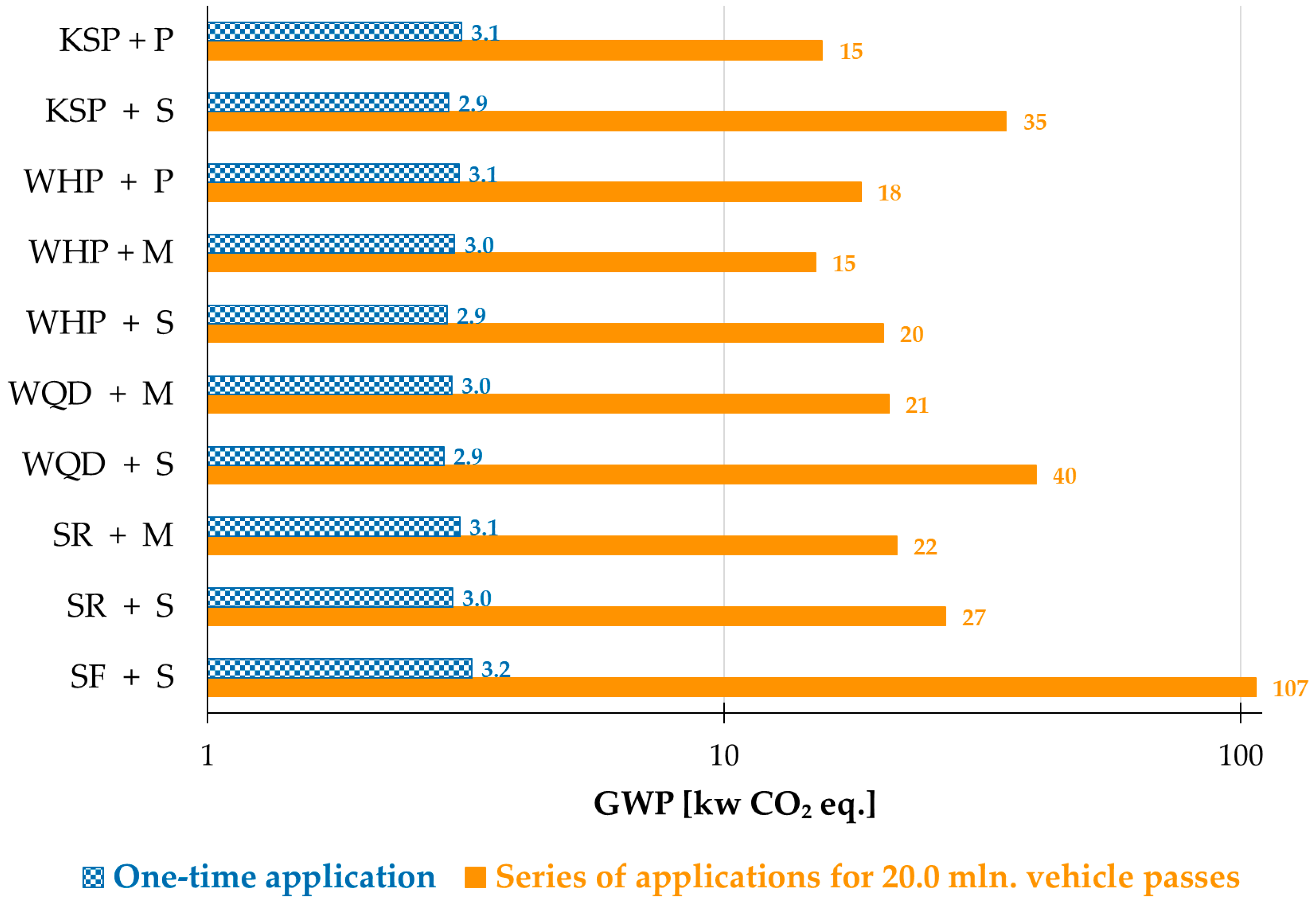

Table 1.
Function of the layers of road markings and selected materials.
| Layer | Coating layer | Retroreflective layer (drop-on material) |
|---|---|---|
| Functions | Adhesion to road surface. Colour contrasting with the roadway. Surface for retroreflection. Adhesion surface for retroreflective layer. |
Retroreflection. Protection of the coating layer from abrasion. Skid resistance. |
| Selected materials | Paint (solventborne, waterborne). Cold plastic. Thermoplastic. Plural-component (epoxy, urea, urethane, etc.; solventborne or solvent-less). Tapes. |
Glass beads (GBs). GBs mixed with anti-skid particles (ASPs), sometimes called anti-skid agglomerates. ASPs alone (special purposes only). Crystalline elements in lieu of GBs. |
| Application methods | Thin layer: spray. Thick layer: extrusion, screed, roller. Tapes: glue with pressure-sensitive adhesive. |
Drop-on during application (in tapes and some pre-formed materials – during manufacturing). |
| Layer thickness, applied quantity (thin layer) | Paints: wet film 0.3–0.6 mm (up to 0.9 mm) / 0.5–1.5 kg/m², resulting in dry film approximately 0.2–0.4 mm (up to 0.6 mm). Solvent-less materials: 0.2–1.0 mm (up to 1.5 mm) / 0.2–2.2 kg/m². Only flat lines. |
Drop-on application 0.3–0.5 kg/m². Layer approximately 0.05−0.5 mm thick (GBs diameters 0.1−1.0 mm). |
| Layer thickness, applied quantity (thick layer) | Wet film 1.0–6.0 mm / 1.5–7.0 kg/m², resulting in dry film approximately 1.0–6.0 mm; flat lines or structured. | Drop-on application 0.3–0.5 kg/m². Layer approximately 0.1−1.0 mm (GBs diameters 0.2−2.0 mm). |
| Abrasion resistance | Very low or low (except for cold plastic and tapes: very high). | High or very high. |
Table 2.
Materials for the coating layer.
| Material | Typical resin (binder) | Description and comments |
|---|---|---|
| Solventborne paints | Acrylic, alkyd, styrenic (chlorinated rubber is mostly obsolete). Content 10–15%. | Commonly utilised worldwide. Because of relatively short service life mostly suitable for areas with minimal encroachment of vehicles. Can be utilised for renewal of thick layer RMs. Some formulations, nowadays mostly obsolete, contained GBs intermixed with the paint. Dry through evaporation of organic solvents (typical contents 22–28%), thus contributing to tropospheric ozone formation [40]. Applied at wet film builds 0.3–0.5 mm (thicker films not possible due to shrinking during drying). |
| Waterborne paints | Acrylic, styrenic, vinyl, acetoacetate, polyol, etc. Content 15–25%. | Usage varies between regions. Designed for marking of areas of low to moderate exposure to vehicular traffic, can be utilised for renewal of thick layer RMs. Usually more durable than solventborne paints; with some binders affording really high durability [21]. Instead of simple drying, can cure through solvent evaporation combined with an acid-base reaction; quick drying and curing can be achieved with some binders. Because binder is delivered as a dispersion, the use of a coalescent is necessary [41]. Emissions of volatile organic compounds (VOCs) minimised to usually <2%; water content typically 15–20%. Disadvantage of waterborne paints is the need to achieve washout resistance after drying; this period may be quite long in case of cool and humid weather conditions. Applied at wet film builds 0.2–0.5 mm (thicker films not possible due to shrinking during drying), but special high-performance paints can be applied at up to 0.9 mm. |
| Thermoplastic (for thick layer application) | Hydrocarbon and/or esterified rosin. Content 12–17%. | Most commonly used thick-layer material worldwide, known since 1940s, easy to formulate and apply. Solvent-less product, delivered in powdery form, applied from a hot melt (about 200 °C), ready for use immediately upon cooling. Always contains ‘premix’ GBs and coarse fillers. Thermoplastics are often delivered in pre-formed shapes, which are also applied through heat. Thermoplastics are the only RMs designed for slow wear-off (the ‘premix’ GBs are thus exposed to continuously deliver RL; this feature is increasing road safety, albeit at the expense of particulate emissions). The possible use of modified rosin esters as binders (non-polymeric material) brings additional considerations related to the environmental impacts [42,43]. Applied as flat lines (rarely structures) through extrusion or using a screed box in layers 3 mm (range 1–5 mm possible) thick; upon the decrease in properties renewed with another layer of sprayed or extruded thermoplastic. Sometimes it is possible to renew through washing (to augment the exposure of the ‘premix’ GBs). All applications on new road surface demand the use of a primer. Thermoplastic formulations must be modified for the use in a particular climatic conditions. |
| Thermoplastic (sprayed) | Hydrocarbon and/or esterified rosin. Content 15–25%. | Chemically the same as thermoplastic, but typically devoid of the ‘premix’ GBs and ASPs. Applied by spraying at layers 0.3–1.5 mm (layers >1.0 mm with some coarse fillers). |
| Cold plastic (for thick layer application) | Acrylic. Content 20–30%. | Modern solvent-less hard material that furnishes exceptional durability, especially at the stage of physical service life. Delivered as acrylic oligomers and monomers, which polymerise on road surface upon mixing with a peroxide initiator. Always contains intermixed coarse fillers (often also ‘premix’ GBs) that enhance resistance to abrasion. Upon the loss of functional properties, renewed with thin layer applications of paint or sprayed cold plastic. Applied through extrusion (at small surfaces, also by manual rolling or spreading), as flat lines or structures; film builds up to 6.0 mm thick are possible. |
| Cold plastic (sprayed) | Acrylic. Content 35–45%. | Modern emerging solvent-less material furnishing high durability. Delivered as acrylic oligomers and monomers, which polymerise on road surface upon mixing with a peroxide initiator. Can be applied at wet film builds 0.2–1.0 mm (does not shrink upon cure). |
| Tapes | Urethane (rarely other). Content 30–40%. | Advanced solvent-less RMs glued to road surface with a pressure-sensitive adhesive; can also be applied to hot bitumen. Furnish very long service life and exceptional properties (particularly tapes designed for Type II performance). Prohibitively high purchase and installation cost. The only RMs not designed for renewal, but for removal and reapplication upon the loss of properties. |
Table 3.
Selected materials for the retroreflective layer (glass beads).
| Material | RI | Description | Comments |
|---|---|---|---|
| ‘Standard’ GBs | 1.5 | Manufactured in vertical furnaces from ground recycled float glass (glass granulate). Surface defects from production process may be possible. | Most typical GB, currently least expensive, widely available. Diameters used in RM: 0.2–0.8 mm (possible range 0.06–1.0 mm). Permits for obtention of RL <350 mcd/m²/lx and, due to low RI, RW <60 mcd/m²/lx in white paint. |
| ‘Large’ GBs | 1.5 | Manufactured from virgin glass melts. High roundness and surface quality. | Produced for RMs in diameters 0.5–2.0 mm (for other industrial applications, the same type of GBs are made also in smaller diameters). Larger dimensions than in ‘Standard’ GB permit for somewhat improved RW. RL <400 mcd/m²/lx and RW <100 mcd/m²/lx can be obtained in white paint. |
| ‘Premium’ GBs | 1.6–1.7 | Silica-titanate GBs manufactured from virgin raw materials using proprietary process furnishing high roundness and good scratch resistance. | The mildly increased RI provide disproportionally high RL, reaching 1000 mcd/m²/lx and RW <200 mcd/m²/lx in white paint. Purchase cost much higher than for ‘Standard’ or ‘Large’ GBs; recently commercialised and available worldwide in diameters 0.3–1.0 mm. |
| ‘High index’ GBs | 1.9 | Silica-barium-titanate GBs made from virgin raw materials with superior roundness and surface quality. | High RI allows for obtention of RL <1800 mcd/m²/lx and RW <400 mcd/m²/lx in white paint. Nonetheless, high cost and low scratch resistance limit their use to some tapes and airport markings [48,49]. Expensive due to the need of using large quantity of TiO₂. Diameters 0.3–1.0 mm are readily available. |
| ‘Crystalline elements’ | 2.1–2.4 | Barium-titanate or lanthanum-titanate non-glassy spherical crystalline materials. | The high RI leads to diminished RL (<300 mcd/m²/lx), but outstanding RW (>300 mcd/m²/lx) in white RMs. Used mostly in high-end tapes designed for Type II performance [50,51]. Prohibitively expensive. |
Table 4.
Selected materials for the retroreflective layer (anti-skid particles).
| Material | Description | Comments |
|---|---|---|
| Cristobalite sand ASPs | Commonly utilised opaque ASP, >95% SiO₂, contains crystalline silica. | Inexpensive and readily available. Moderate hardness (Mohs scale 6–7). |
| Glass granulate ASPs | The raw material fed to the vertical ovens to prepare the ‘Standard’ GBs can also be used as transparent ASP to enhance skid resistance. | Inexpensive and highly efficient initially. Relatively soft (Mohs scale 5–6) may undergo polishing, which results in quickly diminishing performance [52]. |
| Corundum ASP | Highly effective transparent ASP, >95% Al₂O₃. | Very hard (Mohs scale 9), but costly ASP; usually used in combination with sand. |
Table 5.
Assumed composition of the analysed coating layer materials.
| Coating layer material | Solventborne paint, aromatic-free | Solventborne paint, toluene-based | Waterborne paint, quick-set | Waterborne paint, high-performance | Sprayed cold plastic |
|---|---|---|---|---|---|
| Material code | SAF | SAR | WQD | WHP | KSP |
| Binder (acrylic) | 10.00% | 10.00% | 15.45% | 17.15% | 39.77% |
| TiO₂ (a) | 4.00% | 6.80% | 4.75% | 7.00% | 8.00% |
| CaCO₃ | 58.35% | 55.70% | 51.40% | 50.95% | 49.40% |
| Coalescent (b) | – | – | 3.55% | 1.75% | – |
| VOC emissions | 25.70% | 24.70% (c) | 0.40% (d) | 0.40% (d) | 1.00% (e) |
| Water | – | – | 23.04% | 21.69% | – |
| Other additives | 1.95% | 2.80% | 1.41% | 1.06% | 2.58% |
| Peroxide initiator (f) | – | – | – | – | 1.00% |
(a) Assumed the use of rutile TiO₂ pigment, with purity 92% [53]. (b) Assumed as being not an added VOC, but emitted VOC. (c) Comprising 24.00% toluene. (d) Coalescent excluded. (e) Estimated based on professional knowledge. (f) Considered as post-added. Note that it was excluded from calculations of CF due to the absence of reliable data.
Table 6.
Assumed composition of the analysed retroreflective layer materials.
| Retroreflective layer material | ‘Standard’ GBs | ‘Mixed’ GBs | ‘Premium’ GBs |
| Material code | S | M | P |
| SiO₂ | 58.00% | 39.25% | 28.00% |
| Na₂O | 10.00% | 3.75% | 0.00% |
| Al₂O₃ | 0.00% | 6.25% | 10.00% |
| MgO | 3.20% | 7.45% | 10.00% |
| CaO | 8.00% | 15.50% | 20.00% |
| TiO₂ | 0.00% | 6.25% | 10.00% |
| Other | 0.79% | 1.54% | 1.99% |
| Anti-skid particle (sand) | 20.00% | 20.00% | 20.00% |
| Organosilane coating | 0.01% | 0.01% | 0.01% |
Table 7.
The environmental impacts for the manufacture of 1.0 kg of the tested materials.
| Material type | Coating layer materials | Retroreflective layer materials | ||||||
|---|---|---|---|---|---|---|---|---|
| Impact category (a) | SAF | SAR | WQD | WHP | KSP (b) | S | M | P |
| GWP (total) | 2.68 | 2.24 | 2.06 | 2.11 | 2.59 | 0.78 | 1.04 | 1.20 |
| GWP (fossil) | 2.66 | 2.22 | 2.05 | 2.12 | 2.58 | 0.78 | 0.84 | 0.88 |
| GWP (biogenic) | 0.01 | 0.01 | 0.00 | 0.01 | 0.01 | 0.01 | 0.01 | 0.01 |
| GWP (luluc) | 0.00 | 0.00 | 0.00 | 0.00 | 0.00 | 0.00 | 0.01 | 0.01 |
| AP | 0.01 | 0.01 | 0.02 | 0.02 | 0.02 | 0.00 | 0.01 | 0.02 |
| EP (terrestrial) | 0.02 | 0.02 | 0.02 | 0.02 | 0.02 | 0.00 | 0.01 | 0.01 |
| ADPF | 42.98 | 38.83 | 30.74 | 28.86 | 41.36 | 13.00 | 12.38 | 12.01 |
| WDP | 1.97 | 1.49 | 1.42 | 1.49 | 2.55 | 0.04 | 0.74 | 1.17 |
| PERT | 2.14 | 1.61 | 2.66 | 2.87 | 2.53 | 0.54 | 4.62 | 7.07 |
| PENRT | 46.24 | 41.59 | 32.85 | 30.43 | 44.34 | 14.38 | 9.18 | 6.06 |
| FW | 0.05 | 0.04 | 0.04 | 0.04 | 0.06 | 0.00 | 0.01 | 0.02 |
| NHWD | 0.33 | 0.38 | 0.65 | 0.79 | 0.48 | 0.08 | 0.15 | 0.20 |
| IR | 0.09 | 0.06 | 0.09 | 0.10 | 0.09 | 0.01 | 0.03 | 0.04 |
| ETP | 39.62 | 24.46 | 40.68 | 44.70 | 41.02 | 4.98 | 19.84 | 28.77 |
| SQP | 8.31 | 6.19 | 10.43 | 11.78 | 10.61 | 1.68 | 4.74 | 6.58 |
(a) Abbreviations and units [given in brackets]. Environmental impact components: GWP [kg CO₂ eq.]; GWP (luluc) = Global warming potential – land use and land use change [kg CO₂ eq.]; AP = Acidification potential [mol H⁺ eq.]; EP = Eutrophication potential [kg N eq.]; ADPF = Abiotic depletion potential (ADP) for fossil resources [MJ]; WDP = Water deprivation potential [m³ world eq. deprived]. Indicators to describe resource use: PERT = Total use of renewable primary energy resources [MJ]; PENRT = Total use of non-renewable primary energy resources [MJ]; FW = Use of net fresh water [m³]. Waste categories and output flows: NHWD = Non-hazardous waste disposed [kg]. Additional impact categories: IR = Potential Human exposure efficiency relative to U235 [kBq U235 eq.]; ETP = Potential comparative Toxic Unit for ecosystems [CTUe]; SQP = Potential soil quality index [SQP]. (b) Due to the absence of data, peroxide initiator was not included.
Table 8.
GWP of the analysed RM to maintain functional properties of 1.0 m² of marked surface for 20.0 million weight-adjusted vehicle passes per lane.
Table 8.
GWP of the analysed RM to maintain functional properties of 1.0 m² of marked surface for 20.0 million weight-adjusted vehicle passes per lane.
| Road marking system code (a) | Functional service life (b) | Number of applications needed (c) | GWP [kg CO₂ eq.] per application | Total GWP [kg CO₂ eq.] per series of applications (d) |
|---|---|---|---|---|
| SAF + S | 0.6 | 32 | 3.2 | 107.0 |
| SAR + S | 2.5 | 8 | 3.0 | 26.8 |
| SAR + M | 3.9 | 6 | 3.1 | 21.6 |
| WQD + S | 1.6 | 13 | 2.9 | 40.2 |
| WQD + M | 3.6 | 6 | 3.0 | 20.8 |
| WHP + S | 3.6 | 6 | 2.9 | 20.3 |
| WHP + M | 5.7 | 4 | 3.0 | 15.0 |
| WHP + P | 4.5 | 5 | 3.1 | 18.4 |
| KSP + S | 1.9 | 11 | 2.9 | 35.2 |
| KSP + P | 5.5 | 4 | 3.1 | 15.5 |
(a) For explanations of codes, see Table 5 andTable 6. (b) Given in millions of weight-adjusted vehicle passes per lane until RL <150 mcd/m²/lx; in all of the cases, data for the most used regions (i.e. at wheel tracks) of transverse lines was used to determine the functional service life [21]. (c) Minimum number of renewals to maintain RL >150 mcd/m²/lx for 20.0 million of weight-adjusted vehicle passes per lane.(d) Calculated for a series of renewals to maintain the RL >150 mcd/m²/lx.
Disclaimer/Publisher’s Note: The statements, opinions and data contained in all publications are solely those of the individual author(s) and contributor(s) and not of MDPI and/or the editor(s). MDPI and/or the editor(s) disclaim responsibility for any injury to people or property resulting from any ideas, methods, instructions or products referred to in the content. |
© 2024 by the authors. Licensee MDPI, Basel, Switzerland. This article is an open access article distributed under the terms and conditions of the Creative Commons Attribution (CC BY) license (http://creativecommons.org/licenses/by/4.0/).
Copyright: This open access article is published under a Creative Commons CC BY 4.0 license, which permit the free download, distribution, and reuse, provided that the author and preprint are cited in any reuse.


