

Submitted:
10 December 2024
Posted:
11 December 2024
You are already at the latest version
Abstract
The goal to reduce greenhouse gas emissions necessitates the increase of RES utilization. To accomplish this goal, energy storage solutions, are required. This study investigates the performance of an electrothermal energy storage system, the CEEGS system, which consists of an above surface energy storage system and a below surface geological system. The focus is set initially on the analysis of the above surface system to gain insight on its operation. Then steady-state optimization is utilized to identify the operating condition that maximize the system performance, before investigating the bellow surface system integration and the effect that the geological conditions have on system performance. For the above surface system, efficiency (ηR-T) up to 46.89 % is calculated. For system integrated with CO2 geological storage, two case studies are examined, presenting higher ηR-T compared to the above surface system (Case study 1-50.37 %, Case study 2-67.39 %). The optimal ηR-T for Case 2 is achieved for higher injection/production pressures and temperatures conditions and minimal ΔP and ΔT between injection and production. In conclusion, it is the selection of the geological storage conditions that contribute the most to the optimal ηR-T thus the selection of the appropriate geological storage formation is imperative.
Keywords:
electrothermal energy storage
; transcritical CO2 (TCO2)
; CO2 geological storage
; Parametric sensitivity analysis
; Steady-state optimization
1. Introduction
The Paris Agreement set the ambitious goal of maintaining the increase in the global temperature lower than 2 °C and if possible, below 1.5 °C compared to pre-industrial levels [1]. This goal is directly connected to the aim of reducing greenhouse gas emissions originating from the use of fossil fuels in energy production. The reduction of the use of fossil fuels appears in fact feasible since, coal, oil and natural gas as a share of the total energy mix will reach a maximum of approximately 80 % within this decade and will decrease to 73 % in 2030 if the relevant policy decisions are enforced [2]. At the same time however, the population worldwide is set to increase by 1.7 billion people by 2050 which will result to a corresponding increase in the global energy demand. Since the use of fossil fuels is projected to decrease, the increase in the energy demand will need to be met by an increase in the use of renewable energy (RE).
RE however has its own disadvantages since it is characterized by the intermittency of the corresponding energy supply which depends on factors such as the time of day, the weather and season, as well as the location of the installed capacity. To mitigate this issue, which leads to periods of either excess generated energy that needs to be curtailed or energy scarcity, energy storage (ES) solutions must be applied. Specifically for large capacity ES, pumped hydro and compressed air are suggested as the most suitable methods [3] with the former, despite its limitation since it requires certain topological characteristics, currently having the largest share of the energy storage market; namely, more than 95 % [4]. Another group of ES methods reported in literature consists of those associated with the Carnot Battery concept. This method is used to describe a wide range of ES methods which operate by converting electric energy to thermal (charging phase) and then thermal back to electric (discharging phase) [5]. In the Rankine pumped thermal energy storage (Rankine PTES) Carnot Battery method the charging phase is conducted by a heat pump Rankine cycle and the discharging phase by a heat engine one, while cold and hot thermal energy storage (TES) units are used to store the thermal energy [5]. In contrast Brayton PTES [6], for the same process Joule–Brayton cycles are used. Rankine PTES is of specific interest among the different types of Carnot Battery methods since it can operate for temperatures between -30 °C and 400 °C and pressures between 1 bar and 200 bar [5]. Compared to other types of Carnot Batteries, like the Brayton PTES, the narrow temperature span of the Rankine PTES cycles facilitates improved matching of the temperature profiles between the cycles and the TES units [5]. Also, the temperature range of the Rankine PTES method makes it suitable for different types of applications like district or process heating and cooling, as well as utilization for microgrid ES [5]. A large number of studies have been conducted in recent years on the topic of Rankine PTES. Eppinger et al. [7] designed and analyzed a heat pump – organic Rankine cycle PTES system, choosing R1233zd(E) as the working fluid. In the same study, electric-to-electric round-trip efficiency of up to 59 % was calculated. A variation of the base case Rankine PTES system, namely the thermally integrated Rankine PTES (TI-PTES) system, promises higher round-trip efficiencies making use of low-grade heat sources [8]. Through the implementation of multi-objective optimization a round-trip efficiency of 55 % was achieved [8].
The utilization of a heat pump and a heat engine as described in the Rankine PTES system, namely an electrothermal energy storage method (EES) goes back to the concept presented by Cahn [9]. The EES system more recently was introduced again by Mercangöz et al. [10], as a method for energy storage in large quantities. The EES system is comprised of a heat pump (HP) and heat engine (HE) using transcritical CO2 (TCO2) as the working fluid, water for the storage of sensible heat and ice for the storage of latent heat. In the same study, thermoeconomic analysis of the EES system is conducted through modelling and simulations and optimal round-trip efficiencies are found between 51 % and 65 %. In another study, Morandin et al. [11] proceeded to conduct the design and optimization of the EES system having as a focus point the thermal integration of the HP and HE cycles finding an optimal round-trip efficiency of 60 %. Fernadez et al. [12], expand the research in the EES system by considering the addition of solar energy in the form of heat either on the HP or the HE cycle. The authors were able to reach round-trip efficiencies higher than 60 %. The reported round-trip efficiencies of EES systems utilizing TCO2 cycles, are well within the reported range of the Rankine PTES systems (45 % to 65 %) [5].
The EES system initially developed by Mercangöz et al. [10], was redesigned to include the geological storage of the CO2 [13] with the new system CEEGS (CO2-based Electrothermal Energy and Geological Storage system), comprising now of two subsystems, the above surface EES system and a below surface geological energy storage system. This new system achieved a round-trip efficiency approximately between 40 % and 50 %. The CEEGS concept has recently been the subject of a European Union Horizon research project, namely CEEGS-Novel CO2-based Electrothermal Energy and Geological Storage system [14]. Under this concept, further studies have been recently published. The above surface EES system, the one without any geological storage, has been modelled and analyzed with parametric sensitivity analysis implemented to identify the operating conditions which lead to the highest round-trip efficiency (46.90 %) [15]. In the same study, the effect of alternative cold energy storage mediums on the round-trip efficiency is also measured. In a subsequent study [16], the CEEGS system was analyzed and evaluated under a different configuration where salt cavities were used as the geological storage formations with reported round-trip efficiencies between 49.1 % and 73 %. The same study when analyzing the CEEGS system without the CO2 geological storage, reported round-trip efficiencies between 47.3 % and 55.5 %. Finally, a small lab-scale unit (200 kW) of the CEEGS system has been designed and constructed at the Helmholtz-Zentrum Dresden-Rossendorf to validate the concept (TRL 4) [17]. Initial results of the operation of the system (charging phase) were presented and valuable observations were made for the future enhancement of the process in ref. 17.
The use of supercritical CO2 as the heat transmission fluid in geothermal-related applications was originally introduced by Brown [18]. The proposed method coupled a novel enhanced/engineered geothermal system (EGS) with partial geological sequestration of CO2. The partial CO2 sequestration provided additional economic benefit and incentive for future CO2 management scenarios. EGS systems are typically generated via hydro-fracturing hot dry rock. The thermodynamic and transport properties of CO2 are such that the novel system using CO2 was found superior to the corresponding case of using water as the working fluid for heat extraction [19,20,21]. A significant advancement occurred when, instead of fractured systems, other existing high-porosity, high-permeability geologic reservoirs, overlain by a low-permeability cap-rock, were used. Such systems were referred to as CO2-plume geothermal (CGP) systems [22,23].
The present study has developed an analysis and evaluation methodology of the CEEGS system, including the implementation of the optimization of the integrated above surface EES system and below surface CO2 geological storage system (CEEGS). Moreover, the operating and geological storage conditions, as well as the TES parameters that led to the optimal efficiency of the system have been studied. Through the aforementioned analysis and evaluation of the integrated CEEGS system, the main aim of the current work, is to identify the CO2 geological storage conditions under which the system can operate with the optimal overall efficiency. Moreover, the appropriate above surface system operational conditions that match the optimal geological storage conditions will also be investigated and calculated. The next challenge, for future research, will be the investigation of the dynamic behavior of the critical parameters of the system for different RE production profiles and geological storage scenarios. In the present study, focusing initially on the above surface EES system, a maximum round-trip efficiency of 46.89 % is calculated with the performance of the discharge cycle having the most significant effect on this result. In terms of the integrated CEEGS system with the inclusion of the below surface CO2 geological storage system, two case studies were investigated. The optimal round-trip efficiencies (Case Study 1: 50.37 %, Case Study 2: 67.39 %) are improved compared to the system without geological storage which indicated the advantages of the geological storage integration. Moreover, and by further analyzing the geological storage integration through the two case studies, the importance of the geological conditions towards the overall system performance is identified and discussed. The structure of the rest of the article is as follows. In section 2, the CEEGS system and the models used for its simulation are described and analyzed. In section 3, the methodologies that were implemented are explained while in section 4, the results of the study are presented in detail and analyzed. In section 5, the results of the previous section and the conclusions made are discussed in a broad context along with potential future research outlooks. Finally, the article finishes with the conclusions in section 6.
2. System and Model Description
2.1. The CEEGS System
A schematic depiction of the CEEGS concept is shown in Figure 1. The CEEGS system comprises of two integrated subsystems; namely, (i) an above surface EES system, and (ii) a below surface CO2 geological storage system. In this study the geological storage system is considered to be an open porous media reservoir that includes injection and production wells, in the simplest configuration, adopted in this article, a doublet of wells, hereafter designated as Well A and Well B. In particular, well A which is used as an injection/production well, and well B which is used as an injection well. During the charge phase, surplus of electric energy produced through RE sources like solar or wind is converted into thermal energy, utilizing a transcritical CO2 vapor-compression cycle (Heat Pump - HP), and it is stored in hot and cold TES mediums. The CO2 (working fluid) enters the cycle from an above surface pipe or stationary source and exits the cycle by being injected in well A. During the discharge phase, the thermal energy stored in the TES mediums is converted back into electric energy, utilizing another transcritical CO2 power cycle (Heat Engine - HE), before being distributed to the network for consumption. The CO2 enters the cycle from well A where it was previously stored, having converged to thermal equilibrium with the reservoir and possibly retrieving some geothermal heat, and exits the cycle by being re-injected in well B. Part of the CO2 will move from well B to well A while another smaller part will be permanently sequestered inside the underground reservoir [13]. The quantity of CO2 that will be sequestered is site-dependent and could be up to 13 % of the injected amount [24].
The system can operate in two different modes/configurations. In the first mode (Figure 2), the system works only as an above surface EES system where the HP and HE cycles work as closed cycles, with CO2 being the primary working fluid of both cycles. In that case no CO2 sequestration in the subsurface reservoir can be achieved. On the other hand, in the second mode (Figure 3), as described in the beginning of the subsection, the HP and HE cycles operate as open cycles integrating the below surface CO2 geological storage system, where partial CO2 sequestration can be achieved.
2.2. System Characteristics and Operation
2.2.1. Working and Secondary Fluids
Both cycles, use CO2 as the working fluid, chosen for its various advantages [10]. Its main advantage is related to the operating conditions of the two transcritical cycles. Its low critical point (31.1 °C, 73.8 bar) in terms of the temperature makes it ideal to match with heat storage fluids such as water since the supercritical temperatures that the CO2 will reach allow the transfer of thermal energy to and from water at relatively low water temperatures while maintaining the water’s liquid phase at an appropriate pressure value. In contrast, its critical pressure is higher compared to other refrigerant fluids which could put a strain to the turbomachinery equipment and increase its cost, an issue that can be mitigated by constraining the maximum pressure that the CO2 will reach. Other advantages, connected to the use of CO2 as the working fluid compared to others are its increased power density, its environmental characteristics, as well as other features such as its non-flammability, non-toxicity and low cost. In terms of the secondary fluids used for the two cycles, for the hot TES medium water was selected in its liquid form to store the sensible thermal energy due to various factors. Initially, water compared to other energy storage materials, can store the same amount of energy in less mass or volume, meaning it has increased heat capacity [10]. At the same time, it presents additional favorable characteristics in terms of heat transfer characteristics and price. Finally, for the other secondary fluid, a refrigerant was chosen, namely the hydrochlorofluorocarbon (HCFC) R-22 which allows for the storage of latent thermal energy at a temperature close to the one of ice at 0 °C for the appropriate pressure [25]. By choosing R-22, the presence of a solid phase, in addition to the liquid phase, that would occur with the use of ice slurries is avoided. Thus, any computational difficulties associated with the presence of the solid phase are reduced.
2.2.2. Operation Description
The CEEGS process for the first configuration (Figure 2) starts with the charge phase at the HP cycle (Figure 2a) during periods of excess electricity production. CO2 in a subcritical state (vapor) enters the compressor COMP where the electrical energy input, in the form of work (WCOMP), originating from the surplus of RE sources compresses it isentropically to a supercritical state. The CO2 having reached its maximum pressure and temperature in the HP cycle enters the condenser CON1 flowing isobarically and in a counter current configuration compared to the water (i.e., first “secondary fluid”). The water enters CON1 from stream LTW1, originating from a low temperature water tank. During the heat transfer process, the CO2 releases sensible heat to the water with the water exiting the CON1 at an increased temperature (stream HTW1) and is stored in a high temperature water tank. The CO2 exits the CON1 still at a supercritical state but at decreased temperature and enters the hydraulic turbine HT where it expands isentropically producing useful energy in the form of work (WHT). Exiting the HT the CO2 is now at a subcritical state and it flows through the evaporator EVA1 isobarically and in a counter current manner to the R-22 (i.e., second “secondary fluid”) entering the EVA1 from stream R22_IN1. The CO2 having absorbed latent heat from the R-22 exits the EVA1 and the HP cycle closes at the block Loop_breaker_1, while the R-22 having released latent heat exits the EVA1 at stream R22_OUT1 and is stored in the cold TES medium tank.
During periods of electric energy scarcity, the discharge phase at the HE cycle (Figure 2b) is activated. Liquid CO2 at subcritical state enters the pump PUMP and is compressed isentropically using work (WPUMP). The CO2 having reached its maximum pressure in the cycle enters the evaporator EVA2 flowing isobarically and in a counter current manner to the water which enters EVA2 from stream HTW2 from the hot temperature water tank that was being stored. The hot water releases its stored sensible thermal energy to the CO2 and exits the EVA2 at a reduced temperature at stream LTW2 from where it is stored to the cold temperature water tank. The CO2 exits the EVA2 at its maximum temperature in the cycle having absorbed the sensible thermal energy and it then proceeds to enter the turbine TURB where it expands producing useful work (WTURB) that can then be converted to electric energy and be provided to the network. The CO2 exits the TURB at a subcritical state and flows through the condenser CON2 isobarically and in a counter current manner to the R-22 which enters the CON2 from stream R22_IN2. The CO2 exits the CON2 at a liquid phase having released latent heat to the R-22 and the HE cycle closes at the block Loop_breaker_2. Similarly, the R-22 exits the CON2 at stream R22_OUT2 having absorbed latent heat and is stored within the cold TES medium tank.
The CEEGS process for the second configuration (Figure 3) functions in the same manner as the first CEEGS configuration (Figure 2) with the addition of the CO2 geological storage process. However, in this case (Figure 3a), during the charge phase, the CO2 expands flowing through the turbine TURB2 and enters a geological structure still at a supercritical state at stream WELL_A_IN. Through this expansion work WTURB2 is generated to be used for the operation of the cycle. The section VALVE1, HT and VALVE2 (orange rectangle shown in Figure 3a) is not operating in this operation mode. During the discharge phase (Figure 3b), the CO2 exits the geological structure, where it was previously stored, at stream WELL_A_OUT still at a supercritical state and is compressed (WCOMP2) by COMP2, to reach the required cycle pressure. Having flowed through the HE cycle as described for the first configuration (Figure 2b), the CO2 exits condenser CON2 in a liquid state and is compressed (WPUMP2) by pump PUMP2 re-entering the geological formation at stream WELL_B_IN. The section VALVE4, PUMP1 and VALVE3 (orange rectangle shown in Figure 3b) is not active in this operation mode.
2.2.3. Pressure Parameters
The operation of each of the two cycles (HP, HE) and the flow of the working fluid (CO2) occurs between two pressures, a minimum (PHP, min, PHE, min) and a maximum (PHP, max, PHE, max), since the condensation and evaporation processes in each cycle are isobaric [9]. For the maximum pressures (PHP, max, PHE, max), these must be above the supercritical point (73.8 bar) since the cycles are transcritical, however, they shouldn’t exceed a level above which turbomachinery and cost constraints will appear. At the same time, the maximum pressures and their corresponding temperatures should be such that the water as the secondary fluid will remain in a liquid state for its chosen operating pressure. For the minimum pressures (PHP, min, PHE, min), these must be such that the CO2 is in a subcritical state around the saturation line since flowing through EVA1 (HP) and CON2 (HE) it needs to go through the phase change process exchanging latent heat with the secondary fluid (R-22). At the same time, the selected minimum pressures should be such that the corresponding CO2 temperatures are around 0 °C, close to the phase changing temperature of the secondary fluid R-22 at a pre-defined operating pressure.
2.2.4. Temperature Profiles
Another phenomenon that describes the operation of the two transcritical cycles (HP, HE) of the CEEGS system and affects its round-trip efficiency is the matching of the temperature glides of the CO2 as the working fluid and the ones of the secondary fluids (water, R-22) as the hot and cold TES mediums at the four heat exchangers as described by Mercangöz et al. [10]. To achieve well matched temperature glides which lead to increased values for the round-trip efficiency of the CEEGS system, the transfer of thermal energy between the working fluid and the respective secondary fluid must be either sensible or latent for both fluids. In the case of this system this aim is satisfied since in both cycles, the CO2 and the water both exchange sensible thermal energy while the CO2 and the R-22 both exchange latent heat.
2.2.5. CO2 Geological Storage
The CEEGS system as presented in the second configuration (Figure 3) includes the use of underground geological structures for the injection and production of CO2 during the charge (injection) and discharge (production and injection) phases. In this study, the open porous media reservoirs were chosen for integration with the above surface EES system as studied by Carneiro and Behnous [26]. The selected geological structure consists of two wells which are part of the same open porous media reservoir, the main well A and the secondary well B. Well A functions both as an injection well (HP cycle) and as a production well (HE cycle) while well B operates only as an injection well (HE cycle). For the operation of the CEEGS system, an initial setup phase of a CO2 plume within well A is required [26]. However, the study of this process is outside the scope of this article. The integration between the above surface and below surface systems is mainly related to the pressure and temperature conditions at the injection and production wellhead A with the production conditions to be lower than the injection ones, although the production temperature may, under certain geothermal conditions, be above those of the injection phase [26]. The values that these parameters will take will mostly be affected by the depth of the well, its diameter, and mass flow rates of the CO2, the latter two being design parameters that can be optimized to enhance the efficiency of the system. [26].
However, the pressures and temperatures at the wellhead of well A are also greatly affected by the reservoir properties. Petrophysical parameters of the reservoir, such as permeability and porosity, will affect the bottomhole pressure during the discharge phase, not only due the pressure decrease around well A, but also due to the overall pressure build-up imposed by simultaneous injection of CO2 in well B. The geothermal conditions (reservoir temperature and thermal properties of reservoir rocks) will be paramount for the thermal equilibrium between the injected CO2 and the reservoir temperature near bot-tomhole. In fact, in regions with geothermal heat flow above average, a geothermal heat gain is possible between the charge and the discharge phase.
A full cycle of an energy storage scenario of the CEEGS system is presented in Figure 4a with shut-in periods included. In Figure 4b, a graphical representation of the charge and discharge phases within the below surface formation, as described previously, is shown. At wellhead A both injection (charge phase) and production (discharge phase) are conducted while at wellhead B only injection occurs (discharge phase).
2.3. Mathematical Model
2.3.1. Model Design
In the current study the steady-state mathematical model of the CEEGS system for both operating modes (Figure 2/Figure 3) was developed in gPROMS Process 2023.1.0 [27]. For the CEEGS system to operate at the desired conditions and at the designed level of efficiency and capacity, certain variables or variable differences need to be constraint.
More specifically, and referring to the first configuration (Figure 2), a series of constraints are included in the model to regulate its operation. The power capacity for each cycle (Wnet, HP, Wnet, HE) are selected to be equal. This is achieved by altering the mass flow of the CO2 (ṁCO2, HP, ṁCO2, HE) at each cycle respectively. In the HP cycle, the mass flow of the water (hot TES medium, ṁH2O, HP) is altered to achieve an outlet temperature difference at CON1 of 4 °C. At the same time, the mass flow of R-22 (cold TES medium, ṁR-22, HP) is altered so as the temperature of the R-22 at the exit of EVA1 (TR22_OUT1) is equal to the temperature of R-22 at the inlet of CON2 (TR22_IN2). The temperature of the hot water entering the hot water tank following the operation of the HP cycle (THTW1) is considered equal to the temperature of the hot water tank exiting the tank for the operation of the HE cycle (THTW2). This means that the hot water tank doesn’t present thermal losses. In the HE cycle, the temperature of the CO2 at the exit of EVA2 is altered so as the outlet temperature difference is 4 °C. At the same time, the mass flow of the water as the hot TES medium (ṁH2O, HE) is altered to achieve a water outlet temperature (TLTW2) of approximately equal value as the cold water temperature at the inlet of CON1 (TLTW1). Also, the mass flow of R-22 as the cold TES medium (ṁR-22, HE) is altered so as the temperature of the R-22 at the exit of CON2 (TR22_OUT2) is equal to the temperature of R-22 at the inlet of EVA1 (TR22_IN1).
The second configuration of the CEEGS system (Figure 3), uses mostly the same constraints as described above with a few differences. For this model, the mass flow of the water in the HE cycle (ṁH2O, HE) is altered to achieve an inlet temperature difference at EVA2 of 4 °C. Moreover, the cold water temperature at the inlet of CON1 (TLTW1) is altered to achieve equal temperature with the water outlet temperature (TLTW2) at EVA2. Finally, the CO2 outlet temperature at CON1 is altered to achieve the desired wellhead A injection temperature (TWELL_A_IN).
2.3.2. Thermodynamic Model and Model Assumptions
For the calculation of the thermodynamic properties of each fluid utilized in the CEEGS system the appropriate equation of state (EoS) was selected. For CO2, the GERG-2008 EoS for natural gases and other mixtures was used [28] since it can be applied to CO2 as a pure component making use of the appropriate EoS [29] at the temperature region of -57.15 to 626.85 °C and up to 3,000 bar which covers the use of CO2 in the liquid, gas and supercritical regions for this application. For pure water the IAPWS-95 formulation was selected [30] since it can calculate its thermodynamic properties in a large region from -21.95 to 999.85 °C and up to 104 bar covering the area of the liquid region which is of interest to this application. Finally, for the cold TES medium (R-22) the Peng-Robinson EoS was applied [31] which covers the use of the fluid in the subcritical region for both liquid and gas phases that appear in the CEEGS application.
For the simulation of the models that describe the two CEEGS configurations the following assumptions were made:
- All the fluids (CO2, water, R-22) are considered pure components;
- The kinetic and potential energies are not considered;
- All equipment is considered to operate adiabatically.
2.3.3. Model Evaluation
The evaluation of the first CEEGS configuration (Figure 2) is conducted with the use of three efficiency metrics [13], the efficiency of the HP cycle (Equation 1), the efficiency of the HE cycle (Equation 2) and the round-trip efficiency (Equation 3). While all three metrics will be used for the evaluation of the model, the round-trip efficiency (ηR-T) will be the main evaluation criterion of the overall system.
ηHP = (QCON1 + QEVA1) / (WCOMP - WHT),
ηHE = (WTURB - WPUMP) / (QEVA2 + QCON2),
ηR-T = (WTURB - WPUMP) / (WCOMP-WHT) × (hdis / hchar),
The same efficiency metrics are used for the second CEEGS configuration (Equations 4, 5, 6), adapted to the respective model (Figure 3).
ηHP = (QCON1 + QEVA1) / (WCOMP1 – WTURB2),
ηHE = (WTURB1 - WPUMP2 - WCOMP2) / (QEVA2 + QCON2),
ηR-T = (WTURB1 - WPUMP2 - WCOMP2) / (WCOMP1 – WTURB2) × (hdis / hchar),
QCON1 and QEVA2 correspond to the sensible heat exchanged between CO2 and water during the charge (HP) and discharge (HE) phases respectively while QEVA1 and QCON2 correspond to the latent heat exchanged between CO2 and R-22 for the same cycles respectively. WCOMP and WPUMP are the works needed for the COMP and PUMP respectively while WHT and WTURB are the works generated by the HT and TURB respectively. Similarly, for the second CEEGS configuration, WCOMP1, WCOMP2, WPUMP2 are the works needed for the COMP1, COMP2 and PUMP2 respectively while WTURB1 and WTURB2 are the works generated by the TURB1 and TURB2 respectively. All aforementioned parameters are measured in kW.
In Equations 3 and 6, hchar describes the duration of the charging phase while hdis is the duration of the discharging phase, with both parameters measured in hours (h). The current CEEGS system in both configurations was studied in the scope of daily energy storage meaning, that a full operation of the system (charge and discharge process) is concluded within one day. Having calculated the duration of the discharge of the hot TES tank hdis, hs (Equation 7) and the duration of the discharge of the cold TES tank hdis, cs (Equation 8), the value of hdis (Equation 9) is calculated as the minimum of these two.
hdis, hs = (QCON1 / QEVA2) × hchar,
hdis, cs = (QEVA1 / QCON2) × hchar,
hdis = min (hdis, hs , hdis, cs),
3. Implementation
For the simulation and analysis of the CEEGS system two methodologies were selected for implementation which are presented in this section. Initially, parametric sensitivity analysis was implemented on the model of the first CEEGS system configuration (Figure 2) with the aim of analyzing its operation and evaluating its performance under different above surface operating conditions in the absence of the below surface geological storage subsystem. In addition to the evaluation of the efficiency metrics of the system, the sensitivity analysis allows for the interpretation of critical parameters that characterize its operation. In this manner useful observations for further analysis and evaluation of the system can be made. Furthermore, steady-state single objective optimization was implemented on the model of the second CEEGS configuration (Figure 3) to evaluate the CEEGS system performance in whole for different geological storage case studies and compare those performances with the one of the system without geological storage that was generated from the sensitivity analysis. This will help identify how the addition of the geological storage subsystem affects the system’s performance and locate the most favorable geological storage conditions.
3.1. Parametric Sensitivity Analysis: First CEEGS Configuration
The model (Figure 2) was validated against the one developed by Carro et al. [13] and Kyriakides et al. [15] the latter of which simulated the system in Aspen Plus. Sensitivity analysis was then performed with two sensitivity analysis variables being chosen, namely PHP, max and PHE, max. For both variables the lower bound was chosen as 73.8 bar (CO2 critical pressure) and the upper bound as 220 bar. The lower bound was chosen as such since for both cycles the CO2 needs to be at a supercritical state when exchanging thermal energy with the water while the upper bound was constrained below 220 bar due to turbomachinery and cost reasons. The rest of the input data used in the model are shown in Table 1. The purpose of this analysis is to understand under which operating conditions of the above surface model in the absence of the effect of the CO2 geological storage the highest round-trip efficiencies of the system appear. Specifically, the operating conditions analyzed are the PHP, max and the PHE, max believed to be the parameters that have the most significant effect on the round-trip efficiency of the system [13].
3.2. Steady-state Optimization: Second CEEGS Configuration
Steady-state single objective optimization was applied on the second CEEGS configuration (Figure 3), for two different CO2 geological storage case studies. For both geological storage scenarios, the assumption was made that contrary to the example in Figure 4a, the charge and discharge phases are consecutive and no shut-in periods for the wells are considered. In the first case study, the optimization problem was solved using non-linear programming (NLP) with the objective function presented in Equation 10.
with subscript i having values as follows:
i = HP, max; HE, max,
As decision variables, the maximum pressures of the HP (PHP, max) and HE (PHE, max) cycles were selected with the values of the lower and upper bounds presented in Table 2. In addition, a series of equality and inequality constraints were used in the optimization problem (Table 3). In terms of the input variables used, in the first case study (base case), the geological storage conditions, that is the wellhead A injection pressure and temperature (PWELL_A_IN, TWELL_A_IN), wellhead A production pressure and temperature (PWELL_A_OUT, TWELL_A_OUT) and wellhead B injection pressure (PWELL_B_IN), were selected from the open porous media reservoirs data provided by Carneiro and Behnous [26]. To select an appropriate case study for evaluation the available data were screened with the following process described in detail in [32]. Initially, for the selection process, for the injection and production well A geological storage conditions, the same well A is used both for the injection and production process. As a result, out of all the available data for well A only the ones that describe the same wells A were selected in terms of injection and production mass flow rates (ṁWELL_A_IN, ṁWELL_A_OUT), the wells geological features, as well as the bottomhole pressure and temperature. Moreover, a further screening of the possible wells A was conducted choosing, as indicative ones for this study, only the ones for which PWELL_A_IN is 140 bar and TWELL_A_IN is 70 °C. Finally, a decision was made to exclude any wells where the pressure and temperature production conditions show an increase compared to the respective values of the injection conditions since for most wells the available data indicate a pressure and temperature drop between wellhead A injection and production conditions. Of the remaining wells the wellhead A production conditions (PWELL_A_OUT, TWELL_A_OUT) were chosen to have values that show a pressure and temperature reduction compared to the respective injection values which are the average among these remaining wells. In terms of well B, the wellhead B injection pressure was selected as 55 bar [26]. The geological storage conditions for the first case study as described above are presented in Table 4, alongside the rest of the input variables for the first case study, related to the above surface subsystem, specifically the ones that are different from the ones in Table 1 from the previous section. The first case study as described above was selected for analysis and evaluation as a base case to understand how the integration of a specific CO2 geological storage scenario with the above surface subsystem can affect its round-trip efficiency.
In the second case study, the optimization problem was solved again using NLP with a different objective function presented in Equation 11.
with subscripts i and j having values as follows:
i = HP, max; HE, max; WELL_A_IN; WELL_A_OUT; WELL_B_IN,
In addition to the decision variables used in the first case study (PHP, max, PHE, max), for the second case study the geological storage conditions (PWELL_A_IN, TWELL_A_IN, PWELL_A_OUT, TWELL_A_OUT, PWELL_B_IN) are now also decision variables with the values of the lower and upper bounds presented again in Table 2. Also, similarly to the first case study the equality and inequality constraints that were used in the optimization problem are shown in Table 3 with the only difference from the first case being the addition of the ones related to the geological storage conditions (TWELL_A_IN - TWELL_A_OUT, PWELL_A_IN - PWELL_A_OUT). Finally, in terms of the model’s input parameters these are the same as the first case study (Table 4), with the exception of the geological storage conditions which are now decision variables. This second case study was chosen in order to gain insight on the geological storage conditions that should they materialize, the optimal round-trip efficiency would appear for the integrated CEEGS system.
4. Results
4.1. First CEEGS Configuration: Results and Analysis
4.1.1. Operation and Performance of the Individual HP and HE Cycles
Initially, the operation and performance of the first CEEGS configuration is analyzed and discussed using the results of the sensitivity analysis. In terms of the operation of the charge cycle (HP), as the maximum pressure of the cycle (PHP, max) increases and with the minimum pressure (PHP, min) constrained at 30 bar the works at the compressor (WCOMP) and the hydraulic turbine (WHT) should also increase. However, since the capacity of the cycle (Wnet, HP) is fixed, and the mass flow of the cycle (ṁCO2, HP) is adjusted accordingly to achieve this goal the values of WCOMP and WHT stabilize. As it is depicted in Figure 5, the ṁCO2, HP decreases as the PHP, max increases whereas WCOMP and WHT decrease in absolute value before stabilizing.
At the same time, as the PHP, max increases so does the maximum temperature of the cycle at the exit of the compressor COMP, TCOMP_OUTLET. Through the transfer of sensible heat to the water and with the temperatures of the CO2 at the exit of the condenser CON1 (TCON1_CO2_OUTLET) and of the cold water at the entrance of CON1 (TLTW1) fixed, the temperature of the hot water at the exit of CON1 (THTW1) also increases. This would lead for stable mass flow to the increase of the sensible heat at CON1 (QCON1), however that is not the case since QCON1 is affected by the same variation of ṁCO2, HP that was described previously which leads to its reduction. The same is observed for QEVA1, where the reduction of ṁCO2, HP leads to the reduction of QEVA1 whereas for a stable value of the mass flow, the reduction of the vapor fraction at the outlet of the hydraulic turbine would result to the increase of QEVA1. The above observations are depicted in Figure 6.
In terms of the efficiency of the HP cycle ηHP (Equation 1), since the Wnet, HP is fixed, it is only dependent on QCON1 and QEVA1 and thus follows the same decreasing trend with the increase of PHP, max. The ηHP increases and reaches a maximum of 9.6 at PHP, max of 76.72 bar close to the critical pressure of 73.8 bar. At the same pressure, the maximum values of the QCON1 and QEVA1 are also observed at 5,302 and 4,302 kW, respectively. Finally, and for the case of individual cycle analysis, the second sensitivity analysis variable PHE, max has no effect on the ηHP. The ηHP, QCON1 and QEVA1 versus the PHP, max are presented in Figure 7.
In terms of the operation of the discharge cycle (HE), as the maximum pressure of the cycle (PHE, max) increases the works of both the pump, WPUMP and the turbine WTURB increase in absolute values with the net capacity (Wnet, HE) remaining however fixed through the adjustment of the cycle’s mass flow (ṁCO2, HE). The ṁCO2, HE with the increase of PHE, max will first decrease reaching a minimum value and then start increasing again. The above observations are depicted in Figure 8, where the variation of the WPUMP, WTURB and ṁCO2, HE against the PHE, max are shown for two different values of PHP, max at 146.9 bar and 220 bar. Comparing the values of the three variables (WPUMP, WTURB, ṁCO2, HE) for the two different values of PHP, max it is observed that for higher values of PHP, max there is less variation in the values of WPUMP and WTURB with the increase of PHE, max. In terms of the ṁCO2, HE as PHP, max increases the mass flow of the cycle moves to lower values.
In Figure 9, it is observed that the temperature at the outlet of EVA2 (TEVA2_CO2_OUTLET) is not affected by the variations of PHE, max. TEVA2_CO2_OUTLET is only affected by the increase in the temperature of the hot water (THTW) through the transfer of sensible heat caused by the increase of PHP, max (Figure 6). The increase of PHE, max only results to the increase of the temperature of the CO2 at the EVA2 inlet (TEVA2_CO2_INLET). QEVA2 decreases before reaching a minimum and then slowly increasing again due to the similar pattern of the ṁCO2, HE and the increase of TEVA2_CO2_INLET. Similarly, the same behavior is observed for QCON2 due to the profile of the mass flow and the decrease of the temperature of the CO2 at the CON2 inlet (TCON2_CO2_INLET). Finally, with regards to both QEVA2 and QCON2 it is shown that with higher PHP, max values, the heat duties towards the higher values of PHE, max plateau and slightly keep decreasing instead of increasing.
In Figure 10, ηHE and ηHP versus PHE, max are presented. In terms of the efficiency of the HE cycle ηHE (Equation 2) similar to the ηHP, since the Wnet, HE is fixed, it is only dependent on QCON2 and QEVA2. As the two heat duties decrease with the increase of PHE, max, ηHE increases. Also, moving from lower to higher values of PHP, max, ηHE achieves higher values especially at the upper end of the explored range. ηHP, as it has already been mentioned is not affected by changes in PHE, max and it increases only through the decrease of PHP, max. ηHE achieves its maximum value of 0.096 when both sensitivity analysis variables have a value of 220 bar. Finally, it can be concluded that the two efficiency metrics of the two cycles ηHP and ηHE can’t achieve optimal values simultaneously through the variation of PHP, max since the sensitivity analysis variables’ variation leads to opposite results for each metric.
4.1.2. Operation and Performance of the Overall First CEEGS Configuration
The round-trip efficiency of the overall system (ηR-T), that is the integrated two-cycle above surface system is presented in Figure 11a. It is observed that the highest values of the ηR-T are achieved when the values of the sensitivity analysis variables move simultaneously towards the upper end of their range, namely 220 bar. The highest ηR-T of the system is 46.89 % which is accomplished for values of the PHP, max and PHE, max of 217.076 bar and 220 bar, respectively. Since the ratio of the capacity of the two cycles is 1 (Equation 3) and since the duration of the HP cycle (hchar) is constant at 10 hours, it is derived that it is the increase of duration of the HE cycle (hdis) that causes the increase in the ηR-T (Figure 11b). The duration of the discharge cycle (Equations 7, 8, 9) depends on the heat duties at the four heat exchangers of the system. As it has already been observed (Figure 6, Figure 9) for higher PHP, max and PHE, max all heat duties decrease however the rate of decrease for QCON2 and QEVA2 is faster compared to QEVA1 and QCON1 respectively resulting to the increase of hdis. For the best ηR-T, hdis, hs was calculated as 5.61 h and hdis, cs as 4.69 h with the final hdis being 4.69 h. This means that the 16.4 % of the thermal energy of the hot TES tank was not used. Finally, ηHP and ηHE were calculated respectively as 5.45 and 0.095 with the value of the former being close to the lowest ηHP observed while the value of the latter being close to the highest ηHE which leads to the conclusion that favorable performance of the operation of the HE cycle coincides with the favorable performance of the whole system.
4.2. Second CEEGS Configuration: Optimization Results and Analysis
4.2.1. Optimization Results and Analysis: Case Study 1 & 2
In this section, the results of the steady-state optimization of the second CEEGS configuration, the one with the inclusion of the CO2 geological storage, for the two case studies presented in section 3.2, are analyzed and discussed. It is observed (Table 5) that case study 2 has achieved an optimal value of ηR-T of 67.39 % compared to the value of 50.37 % that was achieved in case study 1 and compared to 46.89 % that was achieved without the geological storage. This improvement is accomplished due to the increase in the duration of the discharge cycle (hdis), from 5.04 h to 6.74 h. In fact, both hdis, hs and hdis, cs have increased. In the case of the former parameter, the increase is due to the decrease of QEVA2 by a bigger percentage compared to the decrease of QCON1 while in the case of the latter, the increase is due to the increase of QEVA1 and at the same time the decrease of QCON2. Another improvement in the efficiency of the system, is that the dissipated energy on the TES tanks has decreased from 3.82 % to 2.46 % where in case study 1 the wasted thermal energy originated in the cold TES tank while in case study 2 in the hot one. Comparing the values of the works between the two case studies in the HP cycle the values are almost identical. In the HE cycle for case study 2, it is noteworthy that WCOMP2 and WPUMP2 are now 0 since there is no pressure difference between the outlet and the inlet at COMP2 and PUMP2. As a result, all the available cycle capacity (1,000 kW) is allocated at TURB1 for the production of electricity for the network. Also, as already observed there are variations between the two case studies in terms of the heat duties at the four heat exchangers. The most significant changes are observed at the CO2-H2O heat exchangers of the HP and HE cycles where QCON1 is reduced by 63.25 % and QEVA2 by 73.2%. With regards to the other efficiency metrics, ηHE has also increased in case study 2 to 0.188 from 0.12 in case study 1 which validates the conclusion that was made in section 4.1.2 that favorable values of this metric are observed when the ηR-T has its optimal value. In contrast, ηHP has reduced in case study 2 to 3.6 from 4.29, once again reaffirming the conclusion that the efficiency of the two individual cycles move to opposite directions.
Comparing the performance of the two case studies with the optimal case from the sensitivity analysis of the first CEEGS configuration it is observed that both case studies have higher ηR-T (Case study 1: 50.37 %, Case study 2: 67.39 %) compared to the case without the inclusion of CO2 geological storage (46.89 %). As a result, the integration of the below surface geological storage system has improved the overall performance of the CEEGS system. Once again this is due to the increase of the discharging hours from 4.69 h to 5.04 h (Case study 1) and 6.74 h (Case study 2). Similarly, ηHE has improved from 0.095 to 0.12 and 0.188 while ηHP has decreased from 5.45 to 4.29 and 3.6 respectively. There has also been a reduction in the amount of wasted energy from 16.4 % to 3.82 % and 2.46 % respectively. Finally, in terms of the values of the maximum pressures of the two cycles, PHP, max and PHE, max, for which these results have been achieved PHP, max reduced from 217.076 bar to 180.51 bar and 154.52 bar respectively while PHE, max from 220 bar to 170.33 bar and 140 bar. This means that the turbomachinery requirements for compression and expansion at the two cycles are reduced which is favorable in terms of feasibility and cost of the system.
Looking towards the reason for this significant improvement on the ηR-T, between case study 1 and 2, it is noticed, that both PHP, max and PHE, max have moved towards lower values of pressure close to the values of PWELL_A_IN and PWELL_A_OUT, respectively (Table 6). That is important since in the case of COMP2 the smaller the pressure difference between PHE, max and PWELL_A_OUT the smaller the required compression work will be (indicated also by the active lower bound for PHE, max). At the same time, in case study 2 as in case study 1 PHP, max and PHE, max are close in value, an expected outcome as already observed in Figure 11. With regards to the below surface decision variables, it is noticed that in case study 2 both injection and production pressures and temperatures of well A have moved to the highest possible values of their explored ranges respectively. At the same time the pressure and temperature differences between injection and production at well A are 0. That means that higher values for these measures (indicated also by the active higher bound for TWELL_A_IN and PWELL_A_OUT) and small or 0 pressure and temperature loss through the well can lead to improved round-trip efficiencies. In terms of well B, the decrease from 55 bar to 37 bar in case study 2 has contributed to the increase of ηR-T since now 0 compression work is required at PUMP2 (indicated also by the active lower bound).
With regards to the values of the constraints (Table 7), the temperature difference values at the four heat exchangers are almost identical. In both case studies it is indicated through the active lower bound that a reduction of the temperature difference at the CON1 inlet would lead to an improvement in the ηR-T. It is also observed that TLTW1 and THTW2 have increased and decreased respectively in case study 2 meaning, that the better ηR-T can be achieved for lower hot water temperature. In terms of the mass flows, in case study 2 in the HE cycle the required mass flows for all fluids have decreased while in the HP cycle small variations are only observed. Finally, the active lower bound for the injection and production pressure difference at well A indicate that a potential pressure increase at the production wellhead A compared to the injection one could lead to an even higher ηR-T.
4.2.2. KPI Correlation to Integrated System Efficiency
For the optimal ηR-T results, those of case study 2, an additional parametric sensitivity analysis was conducted to understand the degree of which the most critical parameters of the system affect the ηR-T of the system. The variables for which their effect is evaluated are the maximum pressures of the two cycles (PHP, max, PHE, max), as well as the parameters related to the geological storage conditions (PWELL_A_IN, TWELL_A_IN, PWELL_A_OUT, TWELL_A_OUT, PWELL_B_IN). Two other parameters included in the analysis, are the temperature differences at the inlet of CON1 and the outlet of EVA2. Each sensitivity analysis variable varied in the analysis compared to the values corresponding to the optimal ηR-T by +1/-1 percentage points, where that was feasible. In Table 8, the sensitivity analysis variables along with the values explored are shown.
The results of the sensitivity analysis are presented with the use of a tornado diagram (Figure 12). In the diagram ηR-T values on the right of the vertical line (ηR-T=67.39 %) show an improvement of the ηR-T while any values on the left show a decrease of the ηR-T. In the same diagram, the red horizontal bars indicate a reduction in the sensitivity analysis variable by 1 percentage point and the blue ones an increase by 1 percentage point. From the results it is concluded that only the reduction of PWELL_A_IN leads to an increase of the ηR-T. This outcome validates the conclusion previously made that the existence of a well A where PWELL_A_IN - PWELL_A_OUT<0 can lead to an improvement of the ηR-T. The increase of PWELL_A_IN and decrease of PWELL_A_OUT as shown in Figure 12 also validate the same conclusion, meaning the increase of pressure loss between injection and production wellhead A, leads to the decrease of the ηR-T. In terms of the injection and production temperatures at well A, the decrease of TWELL_A_OUT leads to the highest reduction of the ηR-T while changes of the TWELL_A_IN have no effect either positive or negative. Moreover, the increase of PWELL_B_IN, leads to the reduction of the ηR-T. In terms of the PHP, max and PHE, max, their variation leads for both to the reduction of the ηR-T. Finally, changes on the two selected heat exchanger temperature differences have no effect on the ηR-T. An overall conclusion from Figure 12 is that in the second CEEGS configuration that includes the CO2 geological storage, it is mostly the geological storage parameters (especially at well A), that affect ηR-T the most. The exception is PHP, max that also contributes significantly to the variation of the ηR-T, meaning that the above surface system continues to have a significant role in the overall system efficiency.
5. Discussion and Future Outlook
5.1. Observations and Conclusions
The CEEGS system was analyzed and evaluated under two configurations without (Figure 2) and with (Figure 3) the inclusion of CO2 geological storage.
For the first CEEGS configuration without geological storage parametric sensitivity analysis was implemented to understand the operation of the system and evaluate its performance under the influence of two sensitivity analysis variables, PHP, max and PHE, max. Initially, studying the behavior of the individual cycles during the operation of the system it is observed, that the cycles’, HP and HE, efficiency metrics, ηHP and ηHE, present opposite behaviors with the increase of the PHP, max, meaning that they can never be both optimal for the same value of PHP, max. Instead, if the criterion of the performance of the whole model is these two efficiency metrics (ηHP, ηHE) a more balanced approach should be followed for the selection of the PHP, max value. In contrast, PHE, max only affects the performance of the HE cycle. When studying the whole system, the optimal ηR-T achieved is 46.89 %. This value is achieved for PHP, max and PHE, max values of 217.076 bar and 220 bar, respectively, both being towards the higher end of the range explored (73.8 bar to 220 bar). The high value of ηR-T is related to the duration of the discharging phase which is towards the upper end of the reported values at 4.69 h. At the same time, for the same sensitivity analysis values ηHP and ηHE are calculated as 5.45 and 0.095 respectively and they are located at opposite ends of their reported values, ηHP being towards the lower end and ηHE being towards the upper end. It is observed that the optimal value of the ηR-T correlates with the favorable value of the ηHE which leads to the conclusion that the HE cycle’s performance is more important to the overall round-trip performance of the first CEEGS system configuration than the performance of the HP cycle.
For the second CEEGS configuration with the inclusion of CO2 geological storage, steady-state single objective optimization was used for two case studies. The first case study used as decision variables only the above surface operating conditions (PHP, max, PHE, max) while the geological storage conditions (PWELL_A_IN, TWELL_A_IN, PWELL_A_OUT, TWELL_A_OUT, PWELL_B_IN) were predefined. In contrast, the second case study used as decision variables both above and below surface conditions (PHP, max, PHE, max, PWELL_A_IN, TWELL_A_IN, PWELL_A_OUT, TWELL_A_OUT, PWELL_B_IN). In both case studies appropriate equality and inequality constraints were used for the capacities of the two cycles, the temperature differences at the four heat exchangers and for the second case study for the pressure and temperature differences between injection and production at the well A wellheads. Initially, comparing the optimization results for the two case studies with the sensitivity analysis results of the first CEEGS configuration it is concluded that there is a positive impact in the addition of the CO2 geological storage for the ηR-T of the CEEGS system since it has improved from 46.89 % of the optimal scenario of the sensitivity analysis to 50.37 % of case study 1 and 67.39 % of case study 2. As in the sensitivity analysis observations, the increase in the ηR-T correlates with the increase of the discharging hours. At the same time, the ηHE has improved from 0.095 to 0.12 and 0.188 whereas ηHP has decreased from 5.45 to 4.29 and 3.6 respectively. The amount of wasted energy also reduced from 16.4 % to 3.82 % and 2.46 %, respectively. Finally, improved round-trip efficiencies have been achieved for lower values of the maximum pressures of the two cycles PHP, max and PHE, max which indicates reduced turbomachinery requirements.
Focusing on the two geological storage case studies useful observations can be made for the identification of the appropriate geological storage conditions that can lead to the highest possible ηR-T. With regards to well A, in case study 2 where the ηR-T was significantly higher than case study 1, the wellhead injection and production pressure and temperatures have moved to higher values. At the same time, the pressure and temperature differences between injection and production wellheads is now 0. With regards to well B, the injection pressure has moved to the lowest possible value resulting to a 0 pressure difference at PUMP2. The same outcome is observed at COMP2 since the pressure difference at the compressor is also 0. Both results are expected since the compression requirements at the HE cycle are minimized. In terms of the two cycles, it is also observed, that in case study 2 the mass flows requirements in the HE cycle are reduced while the temperature that the hot water needs to reach is also significantly less. A further parametric sensitivity analysis on case study 2 reaffirms the previous conclusions since it indicates that the pressure loss between injection and production wellhead A is one of the most critical factors for the improvement on the ηR-T. Moving from a pressure loss (PWELL_A_IN - PWELL_A_OUT>0) to a pressure gain (PWELL_A_IN - PWELL_A_OUT<0) has a positive impact on the ηR-T. Finally, TWELL_A_OUT and PWELL_B_IN affect also significantly the round-trip efficiency. Based on the above observations, it can be concluded that in general in the second CEEGS configuration, for the improvement of the ηR-T mostly it is the geological storage parameters that play the biggest role. Nonetheless, above surface parameters as in the case of the first CEEGS configuration also play a significant role such as the PHP, max and PHE, max.
5.2. Comparison to Published Literature
Comparing the ηR-T result of the current article for the CEEGS system without the inclusion of CO2 geological storage, with past research studying similar systems using TCO2 cycles, the reported result of 46.89 % is in between the reported values. For example, the value of 46.89 % is higher than the reported value of 39.1 % of the BEES system presented by Carro et al. [13] and lower than the 51 % [10] and 56.47 % [12] of two other studies. When it is assumed that all the available thermal energy in either the hot or cold TES tank can be discharged for example through the balancing of the tanks with the use of an additional cycle, higher ηR-T can be achieved. In the current study values up to 56.1 % can be reached in this manner compared to 60 % [11] and 59.6 % [12]. One of the most recent studies [16] indicates results very similar to the current model both in the case of misbalanced (47.3 % versus 46.89 %) and balanced (up to 55.5 % versus up to 56.1 %) TES tanks. Finally, the ηR-T results of the current study are also within the reported range of the wider group of Rankine PTES systems (45 % to 65 %) [5].
Similarly, comparing the results of the optimization of the CEEGS configuration with the inclusion of CO2 geological storage of the current article with past literature similar or increased round-trip efficiencies have been achieved. For instance, Carro et al. [13] report values of 49.6 % while for the present work values of 50.37 % (Case study 1) and 67.39 % (Case study 2) have been presented. When the full thermal capacity of the TES tanks is utilized, the corresponding values are 56.2 % versus 52.4 % (Case study 1) and 69.1 % (Case study 2). Finally, Carro et al. [16], when utilizing salt cavities as geological storage structures report ηR-T in the case of misbalanced TES tanks, 22.95 % to 51.54 % and in the case of balanced up to 73.05 %.
5.3. Future Outlook
Future research will aim at investigating the dynamic performance of both CEEGS systems; namely, the first configuration (without the CO2 geological storage) and the second configuration (with the inclusion of CO2 geological storage). First of all, in terms of evaluating different controller algorithms and the closed loop performance. Advanced control schemes, like model predictive control will be tested. The dynamic response of a number of KPIs and critical system parameters will be studied under different operating scenarios, aiming at optimal renewable integration and demand response performance.
6. Conclusions
The first CEEGS configuration, was investigated with parametric sensitivity analysis using PHP, max and PHE, max as sensitivity analysis variables with the results showing, an ηR-T of 46.89 %, ηHP of 5.45 and ηHE of 0.095. The value of the ηR-T is related to the value of the discharging hours (4.69 h) while the efficiencies of the individual cycles have opposite directions, meaning that they can never be both optimal when PHP, max varies. Finally, it is concluded that the performance of the overall system is influenced mostly by the performance of the HE cycle and not the HP cycle. The second CEEGS configuration, was investigated for two case studies with the use of steady-state, single objective optimization. Case study 1 (base case), used as decision variables only the PHP, max and PHE, max, while the geological storage conditions (PWELL_A_IN, TWELL_A_IN, PWELL_A_OUT, TWELL_A_OUT, PWELL_B_IN) were predefined. On the contrast, case study 2 included in the decision variables the geological storage conditions in addition to PHP, max and PHE, max. The results show that both case studies show improved ηR-T compared to the best case scenario of the sensitivity analysis (46.89 %) of the first CEEGS configuration. This result indicates that the inclusion of the geological storage had a positive impact on the ηR-T (50.37 % - Case study 1, 67.39 % - Case study 2). These results were accomplished for lower values of the maximum pressures of the two cycles PHP, max and PHE, max. Moreover, ηHE has improved from 0.095 (sensitivity analysis result) to 0.12 (Case study 1) and 0.188 (Case study 2) while ηHP has decreased from 5.45 to 4.29 and 3.6 respectively. Finally, the amount of wasted energy also reduced from 16.4 % to 3.82 % and 2.46 % respectively. With regards to the comparison of the two case studies of the second CEEG configuration, it is concluded that it is mostly the variation in the geological storage conditions that play the most important role to the increase of the ηR-T from 50.37 % to 67.39 %. Specifically, moving to higher values of pressures and temperatures at the well A wellheads and minimizing or even reversing the pressure loss between injection and production wellheads have the most beneficial impact on the round-trip efficiency of the system. To conclude, the results obtained through the investigation and analysis of the CEEGS system have accomplished the main aim of the present study. Specifically, the operational and geological storage conditions of the integrated CEEGS system that lead to the optimal ηR-T have been identified and presented. Future studies will investigate the CEEGS system, under different operational scenarios, in a dynamic environment to explore the impact the dynamic changes certain parameters have on its operation and performance.
Author Contributions
Conceptualization, A.S., A-S.K. and S.V.; methodology, A.S. and A-S.K.; software, A.S.; validation, A.S. and A-S.K; formal analysis, A.S., A-S.K., J.C., D.B. and G.G.; investigation, A.S., A-S.K., J.C., D.B., G.G. and I.N.T.; data curation, A.S., J.C., D.B. and G.G.; writing—original draft preparation, A.S.; writing—review and editing, A.S., A-S.K., J.C., D.B., G.G., I.N.T., P.S. and S.V.; visualization, A.S., A-S.K., D.B., and I.N.T.; supervision, P.S. and S.V.; project administration, S.V.; funding acquisition, J.C., I.N.T. and S.V. All authors have read and agreed to the published version of the manuscript.
Funding
This research has received funding from the European Union HORIZON Europe project CEEGS-NOVEL CO2-BASED ELECTROTHERMAL ENERGY AND GEOLOGICAL STORAGE SYSTEM, under Grand Agreement Number: 101084376. Views and opinions expressed are however those of the author(s) only and do not necessarily reflect those of the European Union or CINEA. Neither the European Union nor the granting authority can be held responsible for them.
Data Availability Statement
Dataset available on request from the authors.
Conflicts of Interest
The authors declare no conflicts of interest. The funders had no role in the design of the study; in the collection, analyses, or interpretation of data; in the writing of the manuscript; or in the decision to publish the results.
References
- United Nations, PARIS AGREEMENT. Available online: https://unfccc.int/sites/default/files/english_paris_agreement.pdf (accessed on 9 September 2024).
- International Energy Agency, World Energy Outlook 2023. Available online: https://www.iea.org/reports/world-energy-outlook-2023 (accessed on 9 September 2024).
- Koohi-Fayegh, S.; Rosen, M.A. A review of energy storage types, applications and recent developments. J. Energy Storage 2020, 27, 101047. [Google Scholar] [CrossRef]
- International Energy Agency, Renewables 2021 Analysis and forecasts to 2026. Available online: https://www.iea.org/reports/renewables-2021 (accessed on 10 September 2024).
- Vecchi, A.; Knobloch, K.; Liang, T.; Kildahl, H.; Sciacovelli, A.; Engelbrecht, K.; Li, Y.; Ding, Y. Carnot Battery development: A review on system performance, applications and commercial state-of-the-art. J. Energy Storage 2022, 55, 105782. [Google Scholar] [CrossRef]
- Wang, L.; Lin, X.; Chai, L.; Peng, L.; Yu, D.; Chen, H. Cyclic transient behavior of the Joule–Brayton based pumped heat electricity storage: Modeling and analysis. Renewable Sustainable Energy Rev. 2019, 111, 523–534. [Google Scholar] [CrossRef]
- Eppinger, B.; Steger, D.; Regensburger, C.; Karl, J.; Schlücker, E.; Will, S. Carnot battery: Simulation and design of a reversible heat pump-organic Rankine cycle pilot plant. Appl. Energy 2021, 288, 116650. [Google Scholar] [CrossRef]
- Frate, G.F.; Ferrari, L.; Desideri, U. Multi-criteria investigation of a pumped thermal electricity storage (PTES) system with thermal integration and sensible heat storage. Energy Convers. Manage. 2020, 208, 112530. [Google Scholar] [CrossRef]
- Cahn R.P. Thermal Energy Storage By Means Of Reversible Heat Pumping. United States Patent 1978, 4,089,744, A, Millburn N.J., USA.
- Mercangöz, M.; Hemrle, J.; Kaufmann, L.; Z’Graggen, A.; Ohler, C. Electrothermal energy storage with transcritical CO2 cycles. Energy 2012, 45, 407–415. [Google Scholar] [CrossRef]
- Morandin, M.; Maréchal, F.; Mercangöz, M.; Buchter, F. Conceptual design of a thermo-electrical energy storage system based on heat integration of thermodynamic cycles – Part A: Methodology and base case. Energy 2012, 45, 375–385. [Google Scholar] [CrossRef]
- Fernandez, R.; Chacartegui, R.; Beccera, A.; Calderon, B.; Carvalho, M. Transcritical Carbon Dioxide Charge-Discharge Energy Storage with Integration of Solar Energy. J. Sustainable Dev. Energy Water Environ. Syst. 2019, 7, 444–465. [Google Scholar] [CrossRef]
- Carro, A.; Chacartegui, R.; Ortiz, C.; Carneiro, J.; Beccera, J.A. Integration of energy storage systems based on transcritical CO2: Concept of CO2 based electrothermal energy and geological storage. Energy 2022, 238, 121665. [Google Scholar] [CrossRef]
- CEEGS Project. Available online: https://ceegsproject.eu/ (accessed on 18 September 2024).
- Kyriakides, A.S.; Stoikos, A.; Trigkas, D.; Gravanis, G.; Tsimpanogiannis, I.N.; Papadopoulou, S.; Voutetakis, S. Modelling and Evaluation of CO2-based Electrothermal Energy Storage System. Chem. Eng. Trans. 2023, 103, 505–510. [Google Scholar] [CrossRef]
- Carro, A.; Carneiro, J.; Ortiz, C.; Behnous, D.; Beccera, J.A.; Chacartegui, R. Assessment of carbon dioxide transcritical cycles for electrothermal energy storage with geological storage in salt cavities. Appl. Therm. Eng. 2024, 255, 124028. [Google Scholar] [CrossRef]
- Unger S.; Fogel S.; Schütz P.; Chacartegui R.R.; Carro A.; Carneiro J.; Hampel U. The sCO2 Facility CARBOSOLA: Design, Purpose and Use for Investigating Geological Energy Storage Cycles. Proceedings of the ASME Turbo Expo 2024: Turbomachinery Technical Conference and Exposition Volume 11: Supercritical CO2, London, United Kingdom, 24–28 June 2024. [CrossRef]
- Brown D.W. A hot dry rock geothermal energy concept utilizing supercritical CO2 instead of water. SGP-TR-165 Proceedings 25th Workshop on Geothermal Reservoir Engineering, Stanford University, Stanford, CA, 24-26 January 2000.
- Pruess, K. Enhanced geothermal system (EGS) using CO2 as working fluid – A novel approach for generating renewable energy with simultaneous sequestration of carbon. Geothermics 2006, 35, 351–367. [Google Scholar] [CrossRef]
- Pruess, K. On production behavior of enhanced geothermal systems with CO2 as working fluid. Energy Convers. Management 2008, 49, 1446–1454. [Google Scholar] [CrossRef]
- Atrens, A.D.; Gurgenci, H.; Rudolph, V. CO2 thermosiphon for competitive geothermal power generation. Energy & Fuels 2009, 23, 553–557. [Google Scholar] [CrossRef]
- Randolph, J.B.; Saar, M.O. Coupling carbon dioxide sequestration with geothermal energy capture in naturally permeable, porous geologic formations: Implications for CO2 sequestration. Energy Procedia 2011, 4, 2206–2213. [Google Scholar] [CrossRef]
- Randolph, J.B.; Saar, M.O. Combining geothermal energy capture with geologic carbon dioxide sequestration. Geophys. Res. Lett. 2011, 38, 10401. [Google Scholar] [CrossRef]
- Fárkas, P.; Dounya, B.; Gianni, E. , Tyrologou P.; Koukouzas K.; Carneiro J. The Horizon Europe CEEGS project: Deliverable 2.3 - CO2 sequestration potential and impact of charge/discharge cycles on the chemical composition of CO2 stream 2024, GFZ.
- Carro, A.; Chacartegui, R. The Horizon Europe CEEGS project: Deliverable 3.1 – CEEGS cycle, relevant system characterization 2023, University of Seville. [https://ceegsproject.
- Carneiro, J.; Behnous, B. The Horizon Europe CEEGS project: Deliverable 2.1 – Geological scenarios and their characteristics 2023, Évora. [https://ceegsproject.
- Siemens Process Systems Engineering Limited, gPROMS Process 2023.1.0. Available online: https://www.siemens.com/global/en/products/automation/industry-software/gproms-digital-process-design-and-operations/gproms-modelling-environments/gproms-process.html (accessed on 27 August 2024).
- Kunz, O.; Wagner, W. The GERG-2008 Wide-Range Equation of State for Natural Gases and Other Mixtures: An Expansion of GERG-2004. J. Chem. Eng. Data 2012, 57, 3032–3091. [Google Scholar] [CrossRef]
- Klimeck, R. Entwicklung einer Fundamentalgleichung für Erdgase für das Gas- und Flüssigkeitsgebiet sowie das Phasengleichgewicht. Ph.D. Dissertation, Fakultät für Maschinenbau, Ruhr-Universität Bochum, Bochum, Germany, 2000. [Google Scholar]
- Wagner, W.; Pruß, A. The IAPWS Formulation 1995 for the Thermodynamic Properties of Ordinary Water Substance for General and Scientific Use. J. Phys. Chem. Ref. Data 2002, 31, 387–535. [Google Scholar] [CrossRef]
- Peng, D.Y.; Robinson, D.B. A New Two-Constant Equation of State. Ind. Eng. Chem. Fundam. 1976, 15, 59–64. [Google Scholar] [CrossRef]
- Kyriakides, A.S.; Stoikos, A.; Gravanis, G.; Trigkas, D. The Horizon Europe CEEGS project: Deliverable 4.1 – Digital model 2023, The Centre for Research and Technology Hellas.
Figure 1.
The CEEGS concept [14].
Figure 1.
The CEEGS concept [14].
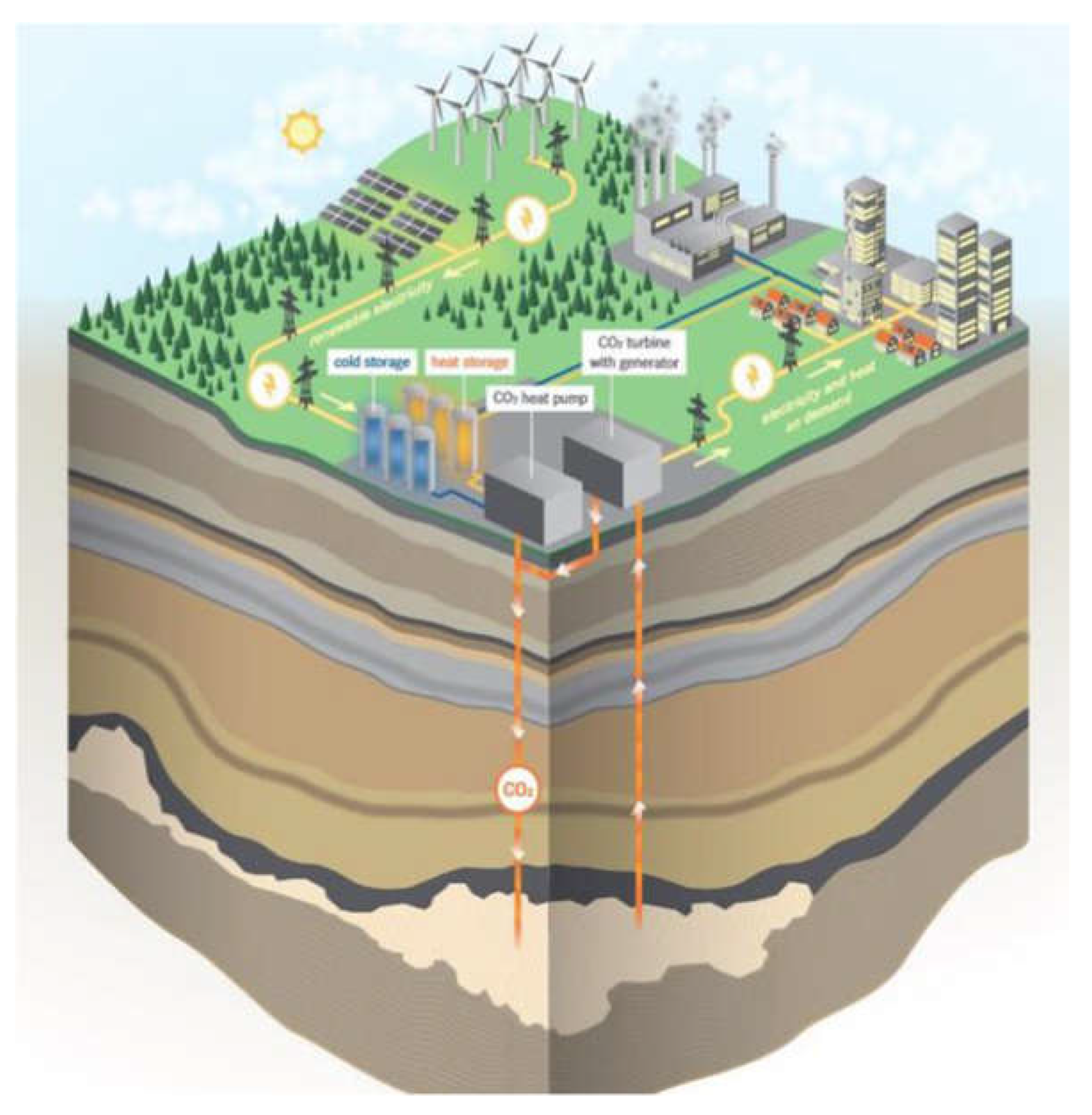
Figure 2.
EES system flowsheet: (a) Charge cycle – HP; (b) Discharge cycle – HE.
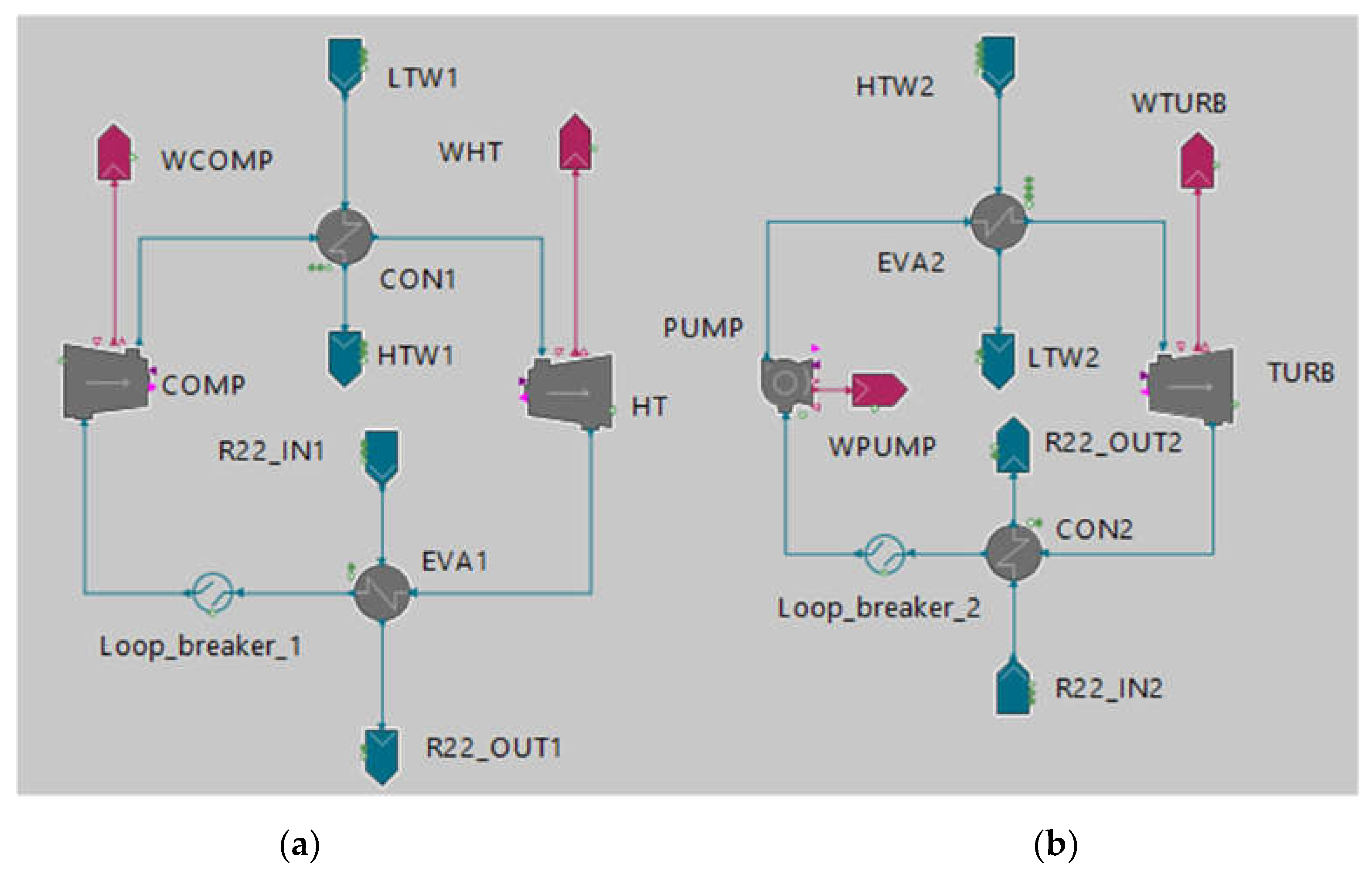
Figure 3.
EES system flowsheet with below surface CO2 storage: (a) Charge cycle – HP; (b) Discharge cycle – HE. The orange rectangles indicate the sections that are not operational for the modes considering CO2 geological storage.
Figure 3.
EES system flowsheet with below surface CO2 storage: (a) Charge cycle – HP; (b) Discharge cycle – HE. The orange rectangles indicate the sections that are not operational for the modes considering CO2 geological storage.
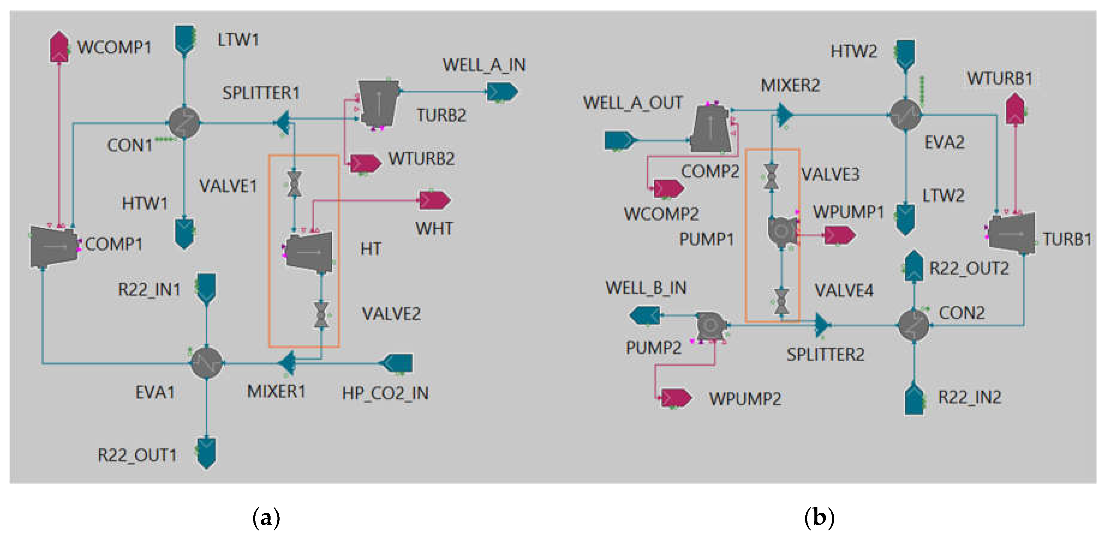
Figure 4.
CEEGS below surface CO2 storage subsystem: (a) CO2 mass flow variation with time during an energy storage scenario; (b) Depiction of the charge-discharge processes within the below surface formation.
Figure 4.
CEEGS below surface CO2 storage subsystem: (a) CO2 mass flow variation with time during an energy storage scenario; (b) Depiction of the charge-discharge processes within the below surface formation.
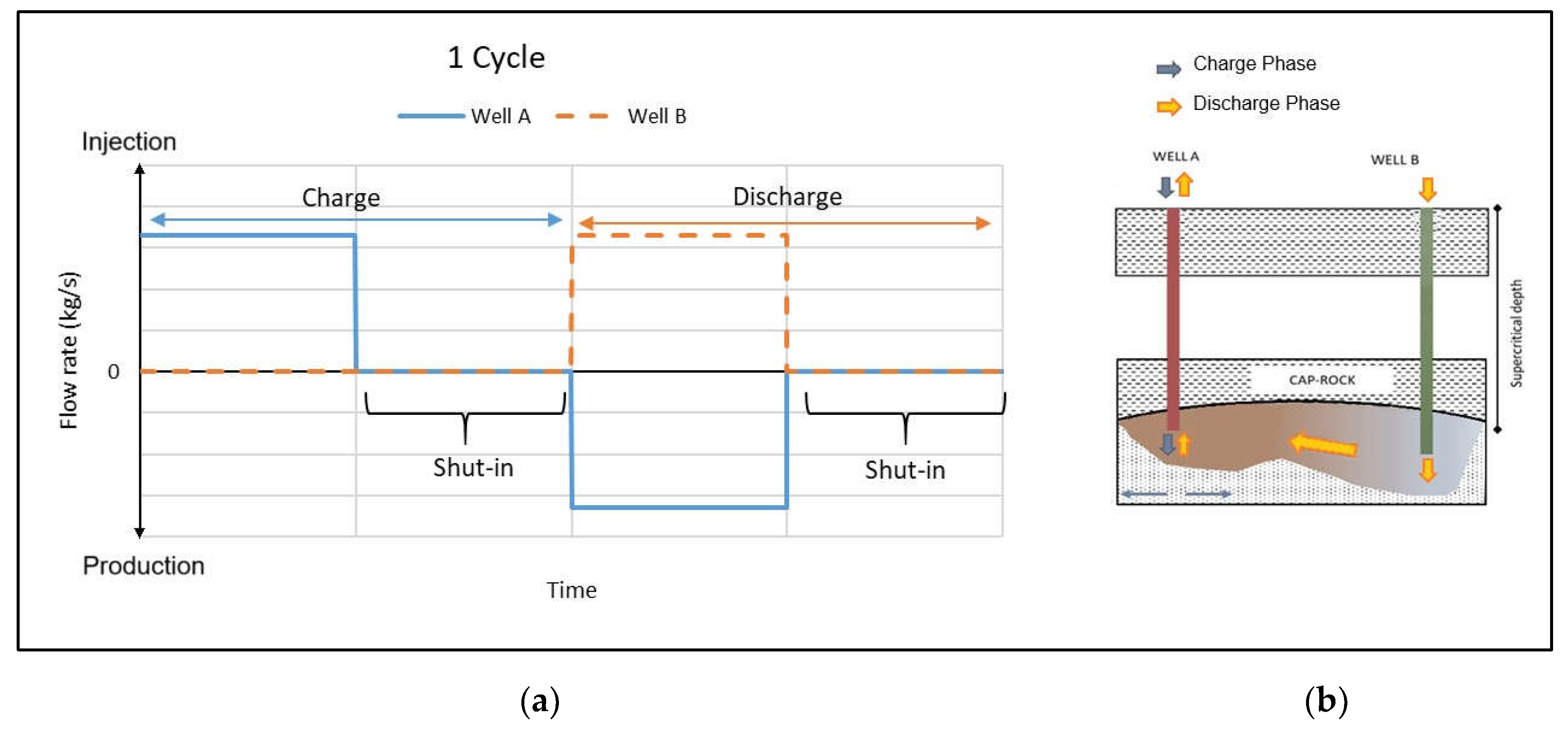
Figure 5.
Parametric sensitivity analysis results: Variation of WCOMP, WHT and ṁCO2, HP versus PHP, max (Dashed vertical line corresponds to the critical pressure of CO2: PHP, max=73.8 bar).
Figure 5.
Parametric sensitivity analysis results: Variation of WCOMP, WHT and ṁCO2, HP versus PHP, max (Dashed vertical line corresponds to the critical pressure of CO2: PHP, max=73.8 bar).
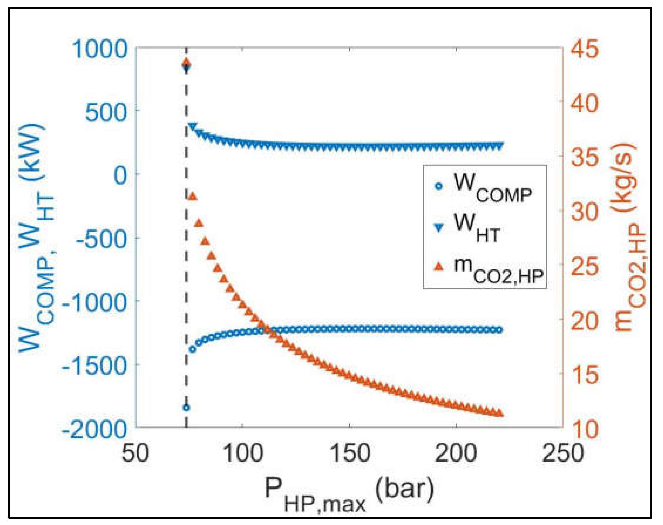
Figure 6.
Parametric sensitivity analysis results: Variation of QCON1, QEVA1 and THTW versus PHP, max (Dashed vertical line corresponds to the critical pressure of CO2: PHP, max=73.8 bar).
Figure 6.
Parametric sensitivity analysis results: Variation of QCON1, QEVA1 and THTW versus PHP, max (Dashed vertical line corresponds to the critical pressure of CO2: PHP, max=73.8 bar).
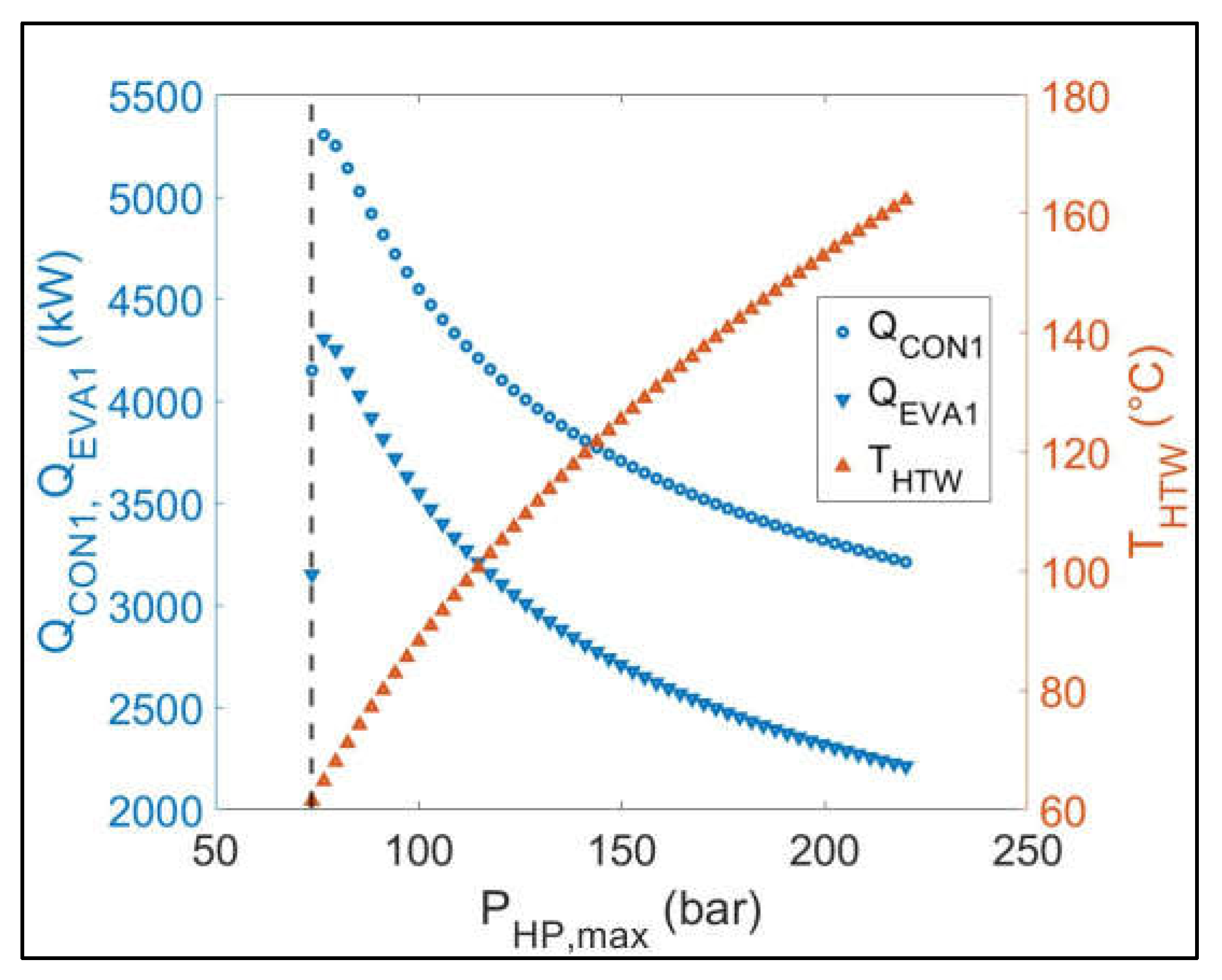
Figure 7.
Parametric sensitivity analysis results: Variation of QCON1, QEVA1 and ηHP versus PHP, max (Dashed vertical line corresponds to the critical pressure of CO2: PHP, max=73.8 bar).
Figure 7.
Parametric sensitivity analysis results: Variation of QCON1, QEVA1 and ηHP versus PHP, max (Dashed vertical line corresponds to the critical pressure of CO2: PHP, max=73.8 bar).
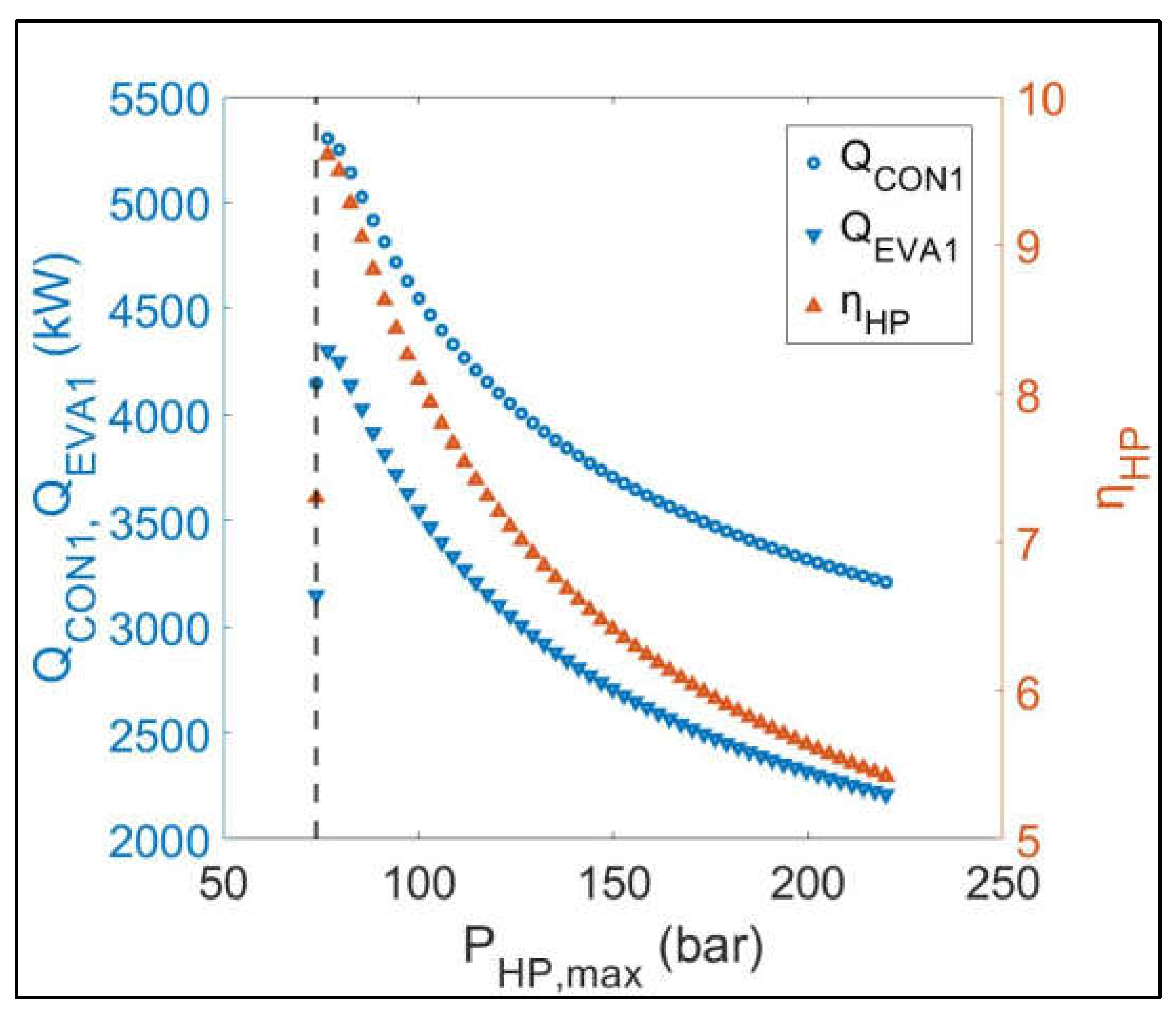
Figure 8.
Parametric sensitivity analysis results: Variation of WPUMP, WTURB and ṁCO2, HE versus PHE, max.
Figure 8.
Parametric sensitivity analysis results: Variation of WPUMP, WTURB and ṁCO2, HE versus PHE, max.
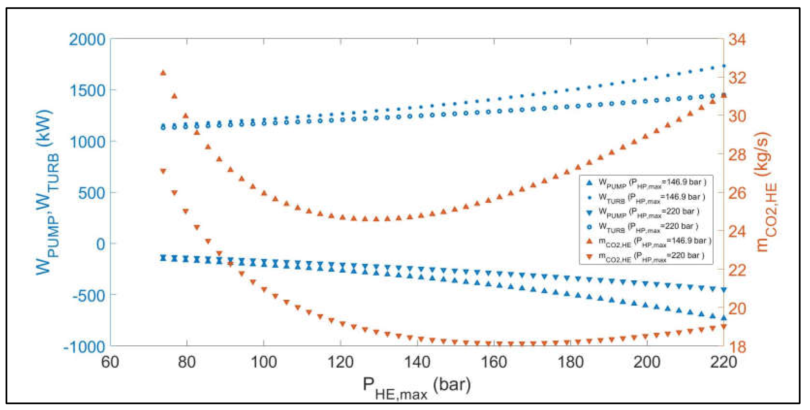
Figure 9.
Parametric sensitivity analysis results: Variation of QCON2, QEVA2, TEVA2_CO2_INLET, TEVA2_CO2_OUTLET versus PHE, max.
Figure 9.
Parametric sensitivity analysis results: Variation of QCON2, QEVA2, TEVA2_CO2_INLET, TEVA2_CO2_OUTLET versus PHE, max.
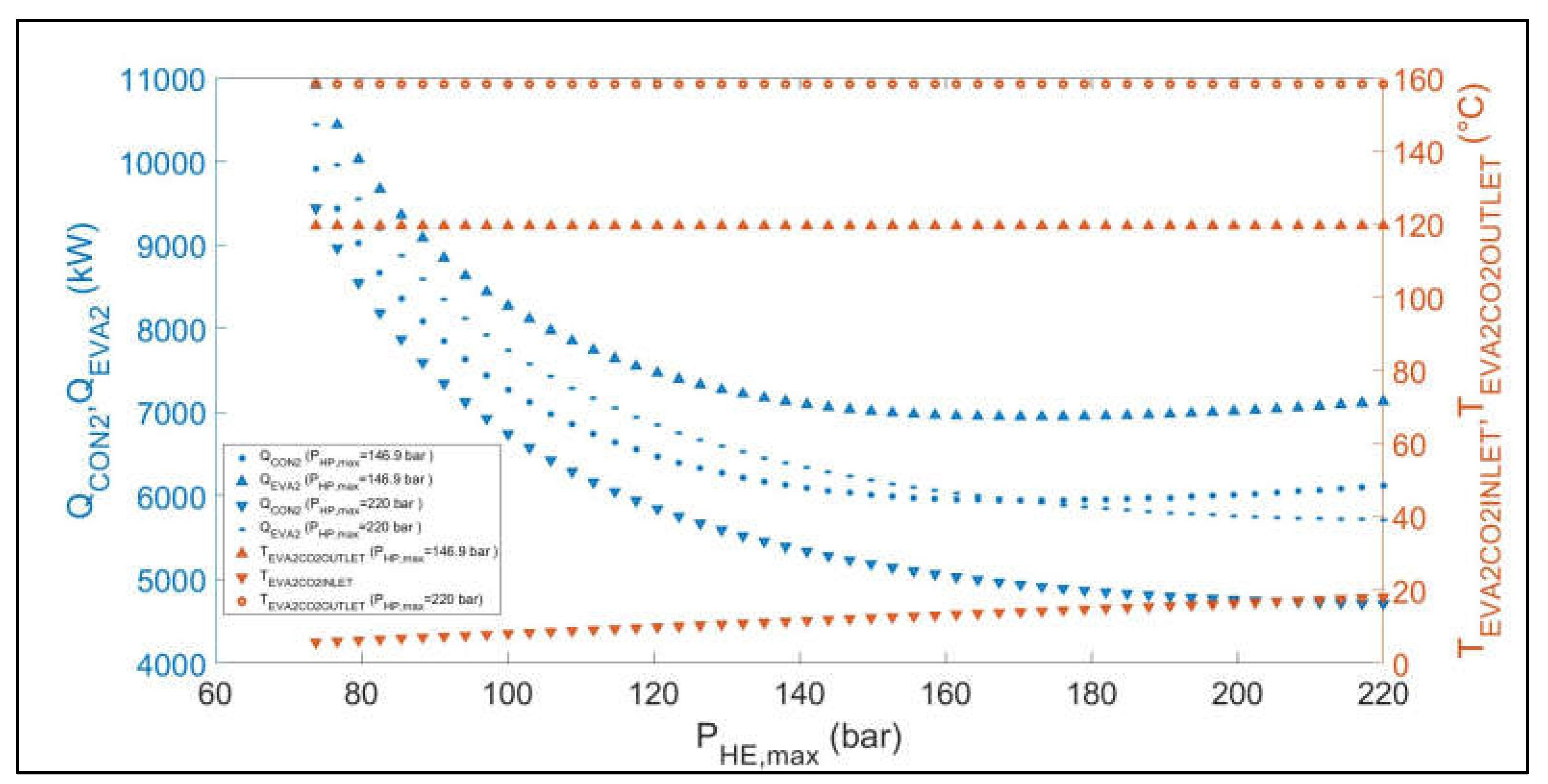
Figure 10.
Parametric sensitivity analysis results: Variation of ηHE and ηHP versus PHE, max.
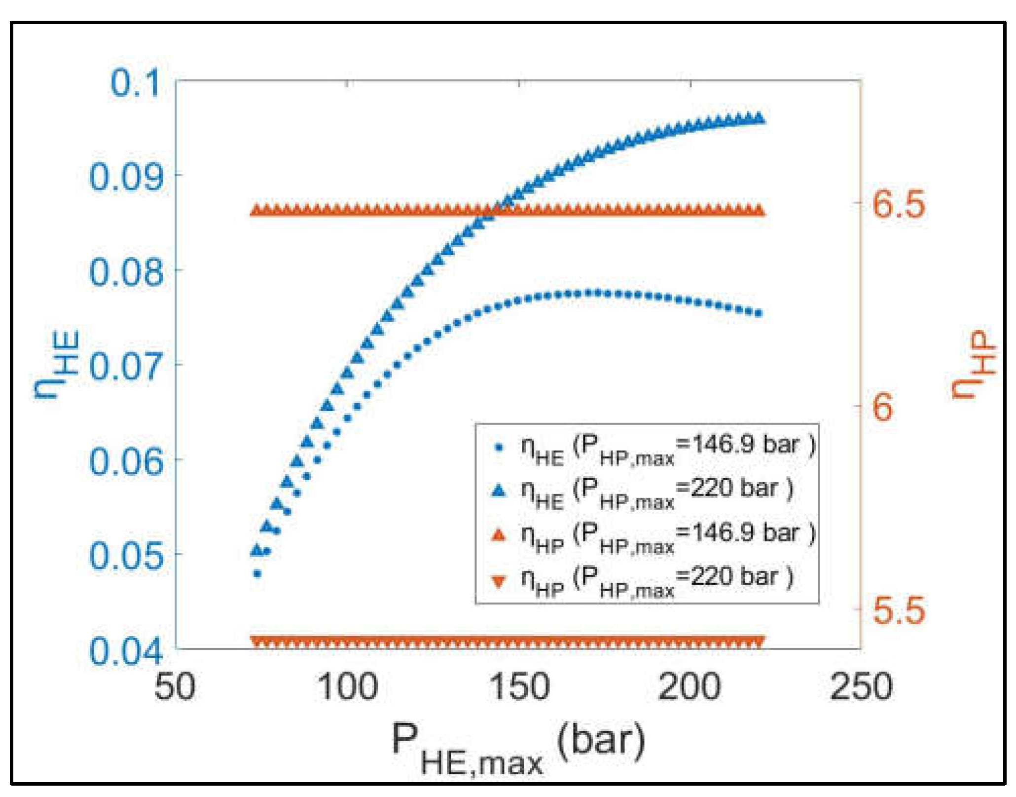
Figure 11.
Parametric sensitivity analysis results: (a) ηR-T versus PHP, max and PHE, max; (b) hdis versus PHP, max and PHE, max.
Figure 11.
Parametric sensitivity analysis results: (a) ηR-T versus PHP, max and PHE, max; (b) hdis versus PHP, max and PHE, max.
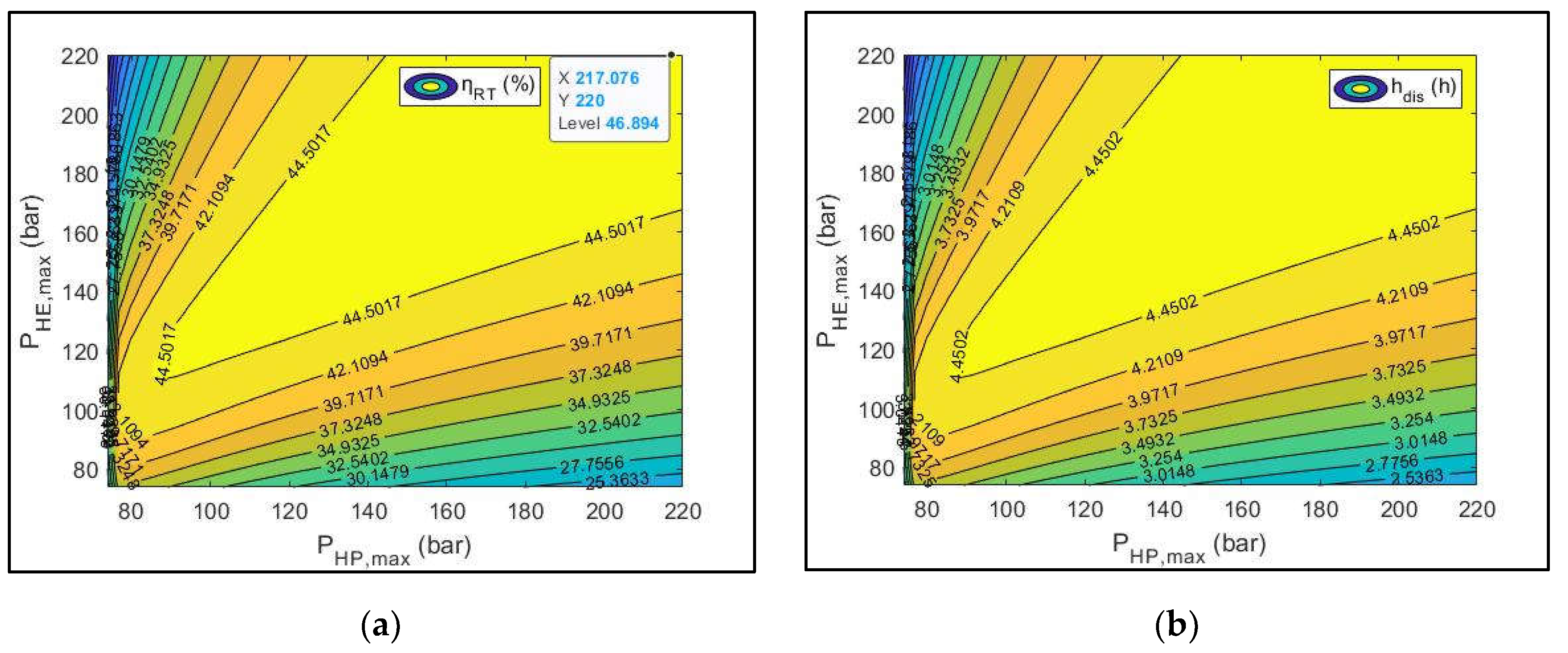
Figure 12.
Parametric sensitivity analysis on the optimal scenario of case study 2.
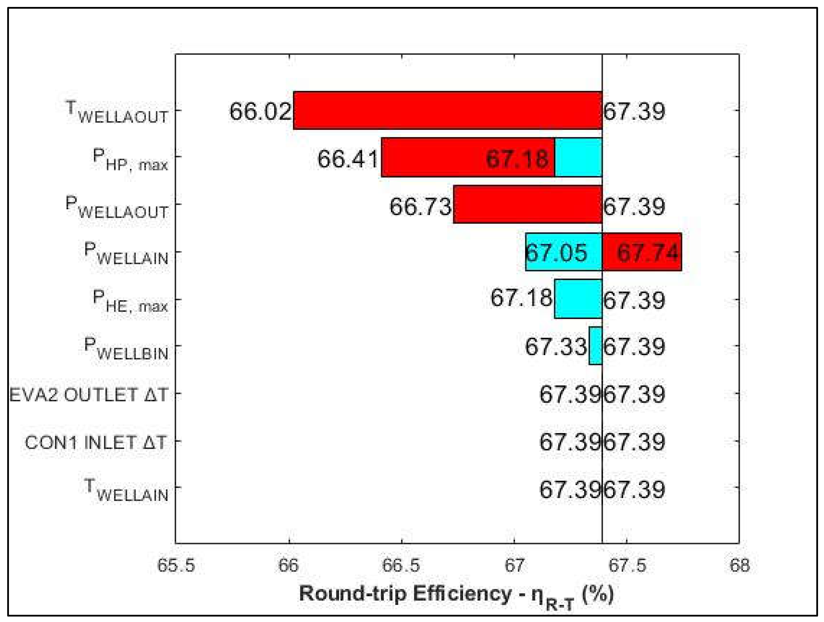

Table 1.
First CEEGS System Configuration: Input data.
| Parameters | Cycle | Equipment | Value | Unit |
|---|---|---|---|---|
| Power capacity HP (Wnet, HP) | HP | - | 1,000 | kW |
| Power capacity HE (Wnet, HE) | HE | - | 1,000 | kW |
| Isentropic efficiency (Compressor) | HP | COMP | 0.86 | [-] |
| Isentropic efficiency (Hydraulic turbine) | HP | HT | 0.85 | [-] |
| Isentropic efficiency (Pump) | HE | PUMP | 0.85 | [-] |
| Isentropic efficiency (Turbine) | HE | TURB | 0.88 | [-] |
| Mechanical efficiency | HP/HE | COMP/HT/ PUMP/TURB | 1 | [-] |
| Minimum pressure HP (PHP, min) | HP | - | 30 | bar |
| Minimum pressure HE (PHE, min) | HE | - | 37 | bar |
| THOT_STREAM_OUTLET | HP | CON1 | 32 | °C |
| Heat exchangers minimum approach temperature |
HP/HE | CON1/EVA1/ CON2/EVA2 | 4 | °C |
| Inlet stream vapor fraction | HP | COMP | 1 | [-] |
| Inlet stream vapor fraction | HE | PUMP | 0 | [-] |
| Pressure – water (PHTW1, PLTW1, PHTW2, PLTW2) | HP/HE | - | 8 | bar |
| TLTW1 | HP | - | 23 | °C |
| TLTW2 | HE | - | 23.1 | °C |
| Pressure – R-22 (PR22_IN1, PR22_OUT1, PR22_IN2, PR22_OUT2) | HP/HE | - | 4.7 | bar |
| TR22_OUT1, TR22_IN2 | HP/HE | - | -1.55 | °C |
| TR22_IN1, TR22_OUT2 | HP/HE | - | 1.52 | °C |
| Charging hours (hchar) | HP | - | 10 | h |
Table 2.
Optimization decision variables: Lower and upper bounds (Case Study 1 & 2).
| Decision variables | Case study | Lower bound | Upper bound | Unit |
|---|---|---|---|---|
| PHP, max | 1/2 | 140 | 220 | bar |
| PHE, max | 1/2 | 105/140 | 220 | bar |
| PWELL_A_IN | 2 | 74 | 140 | bar |
| TWELL_A_IN | 2 | 32 | 100 | °C |
| PWELL_A_OUT | 2 | 74 | 140 | bar |
| TWELL_A_OUT | 2 | 32 | 100 | °C |
| PWELL_B_IN | 2 | 37 | 55 | bar |
Table 3.
Optimization constraints: Lower and upper bounds (Case Study 1 & 2).
| Constraints | Case study | Lower bound | Upper bound | Unit |
|---|---|---|---|---|
| Power capacity HP (Wnet, HP) | 1/2 | -1,001 | -999 | kW |
| Power capacity HE (Wnet, HE) | 1/2 | 999 | 1,001 | kW |
| ṁCO2, HP/HE | 1/2 | 0 | 100 | kg/s |
| ṁH2O, HP/HE | 1/2 | 0 | 100 | kg/s |
| ṁR-22, HP/HE | 1/2 | 0 | 100 | kg/s |
| CON1, Inlet/Outlet ΔT | 1/2 | 4 | 100 | °C |
| EVA1, Inlet/Outlet ΔT | 1/2 | 4 | 100 | °C |
| CON2, Inlet ΔT | 1/2 | 3.8 | 100 | °C |
| CON2, Outlet ΔT | 1/2 | 4 | 100 | °C |
| EVA2, Inlet/Outlet ΔT | 1/2 | 4 | 100 | °C |
| TCON1_CO2_OUTLET | 1/2 | 29.85 | 176.85 | °C |
| TEVA2_CO2_OUTLET | 1/2 | 76.85 | 326.85 | °C |
| TLTW1 | 1/2 | 6.85 | 176.85 | °C |
| THTW2 | 1/2 | 76.85 | 326.85 | °C |
| THTW2 – THTW1 | 1/2 | -0.1 | 0.1 | °C |
| TLTW2 – TLTW1 | 1/2 | 0.09 | 0.11 | °C |
| TWELL_A_IN - TWELL_A_OUT | 2 | 0 | 0 | °C |
| PWELL_A_IN - PWELL_A_OUT | 2 | 0 | 66 | bar |
Table 4.
Second CEEGS System Configuration: Input data (Case Study 1 & 2).
| Parameters | Case study | Cycle | Equipment | Value | Unit |
|---|---|---|---|---|---|
| Isentropic efficiency (Compressor) |
1/2 | HP/HE | COMP1/COMP2 | 0.86 | [-] |
| Isentropic efficiency (Pump) | 1/2 | HE | PUMP2 | 0.85 | [-] |
| Isentropic efficiency (Turbine) |
1/2 | HP/HE | TURB2/TURB1 | 0.88 | [-] |
| Mechanical efficiency | 1/2 | HP/HE | COMP1/COMP2/ PUMP2/TURB1/TURB2 | 1 | [-] |
| PWELL_A_IN | 1 | HP | - | 140 | bar |
| TWELL_A_IN | 1 | HP | 70 | °C | |
| PWELL_A_OUT | 1 | HE | 105 | bar | |
| TWELL_A_OUT | 1 | HE | 50.2 | °C | |
| PWELL_B_IN | 1 | HE | 55 | bar |
Table 5.
Optimization Results (Case Study 1 & 2).
| Parameters | Case study 1 | Case study 2 | Unit |
|---|---|---|---|
| WCOMP1 | 1083.84 | 1050.9 | kW |
| WTURB2 | 83.84 | 50.89 | kW |
| WCOMP2 | 331.17 | 0 | kW |
| WTURB1 | 1380.89 | 999.99 | kW |
| WPUMP2 | 49.72 | 0 | kW |
| QCON1 | 1468.49 | 539.62 | kW |
| QEVA1 | 2819.84 | 3064.56 | kW |
| QEVA2 | 2915.16 | 781.14 | kW |
| QCON2 | 5382.23 | 4547.3 | kW |
| hdis, hs | 5.04 | 6.91 | h |
| hdis, cs | 5.24 | 6.74 | h |
| hdis | 5.04 | 6.74 | h |
| Dissipated energy on hot/cold TES tank | 3.82 | 2.46 | % |
| ηHP | 4.29 | 3.6 | [-] |
| ηHE | 0.12 | 0.188 | [-] |
| ηR-T | 50.37 | 67.39 | % |
Table 6.
Decision variables: Case Study 1 & 2 Optimization Results.
| Decision variables | Case study 1 | Case study 2 | Unit |
|---|---|---|---|
| PHP, max | 180.51 | 154.52 | bar |
| PHE, max | 170.33 | 140 * | bar |
| PWELL_A_IN | - | 140 | bar |
| TWELL_A_IN | - | 100 ** | °C |
| PWELL_A_OUT | - | 140 ** | bar |
| TWELL_A_OUT | - | 100 | °C |
| PWELL_B_IN | - | 37 * | bar |
* Active bound (Lower). ** Active bound (Higher).
Table 7.
Constraints: Case Study 1 & 2 Optimization Results.
| Constraints | Case study 1 | Case study 2 | Unit |
|---|---|---|---|
| Power capacity HP (Wnet, HP) | -1,000 | -1,000 | kW |
| Power capacity HE (Wnet, HE) | 1,000 | 1,000 | kW |
| ṁCO2, HP/HE | 11.42/21.45 | 12.41/17.97 | kg/s |
| ṁH2O, HP/HE | 5.53/11 | 5.17/7.52 | kg/s |
| ṁR-22, HP/HE | 13.41/25.59 | 14.57/21.62 | kg/s |
| CON1, Inlet/Outlet ΔT | 4 */4 | 4 */4 | °C |
| EVA1, Inlet/Outlet ΔT | 4/6.97 | 4/6.97 | °C |
| CON2, Inlet ΔT | 3.83 | 3.83 | °C |
| CON2, Outlet ΔT | 17.37 | 18.94 | °C |
| EVA2, Inlet/Outlet ΔT | 4/4 | 4/4 | °C |
| TCON1_CO2_OUTLET | 84.64 | 107.9 | °C |
| TEVA2_CO2_OUTLET | 139.34 | 124.51 | °C |
| TLTW1 | 80.64 | 103.9 | °C |
| THTW2 | 143.34 | 128.51 | °C |
| THTW2 – THTW1 | 0 | 0 | °C |
| TLTW2 – TLTW1 | 0.1 | 0.1 | °C |
| TWELL_A_IN - TWELL_A_OUT | - | 0 | °C |
| PWELL_A_IN - PWELL_A_OUT | - | 0 * | bar |
* Active bound (Lower).
Table 8.
Parametric sensitivity analysis on the optimal scenario of case study 2: Lower & upper values.
Table 8.
Parametric sensitivity analysis on the optimal scenario of case study 2: Lower & upper values.
| Sensitivity Analysis Variables | Lower value |
Case study 2: Optimal scenario |
Higher value |
Unit |
|---|---|---|---|---|
| PHP, max | 152.97 | 154.52 | 156.06 | bar |
| PHE, max | - | 140 | 141.4 | bar |
| PWELL_A_IN | 138.6 | 140 | 141.4 | bar |
| TWELL_A_IN | 99 | 100 | 101 | °C |
| PWELL_A_OUT | 138.6 | 140 | - | bar |
| TWELL_A_OUT | 99 | 100 | 101 | °C |
| PWELL_B_IN | - | 37 | 37.37 | bar |
| CON1, Inlet ΔT | 3.96 | 4 | 4.04 | °C |
| EVA2, Outlet ΔT | 3.96 | 4 | 4.04 | °C |
Disclaimer/Publisher’s Note: The statements, opinions and data contained in all publications are solely those of the individual author(s) and contributor(s) and not of MDPI and/or the editor(s). MDPI and/or the editor(s) disclaim responsibility for any injury to people or property resulting from any ideas, methods, instructions or products referred to in the content. |
© 2024 by the authors. Licensee MDPI, Basel, Switzerland. This article is an open access article distributed under the terms and conditions of the Creative Commons Attribution (CC BY) license (http://creativecommons.org/licenses/by/4.0/).
Copyright: This open access article is published under a Creative Commons CC BY 4.0 license, which permit the free download, distribution, and reuse, provided that the author and preprint are cited in any reuse.


