
Submitted:
06 December 2024
Posted:
09 December 2024
You are already at the latest version
Abstract
This review compares materials for fiber optics fabrication, focused on polymers for fibers in sensing applications. Polymer based materials are being increasingly deployed in the field of fiber optics sensors. Mainly due to their mechanical flexibility and ease of forming into complex shapes, as required by the design of sensor. One of the additional advantages in some applications as the potential for biodegradability. Optical and mechanical properties are review of the materials commonly used and recently proposed for fiber optics fabrication. Principles of sensing mechanisms for U-shape polymer fiber sensors are discussed. Possible applications of U-shape fiber sensors in fields such as biology, chemistry and industry are presented. This paper aims to provide researchers with guidelines on the factors to consider when choosing a material for bent fiber optic sensors depending on the application.
Keywords:
polymer
; optical fiber
; fiber optic sensing
1. Introduction
Polymer optical fiber (POF) market has shown steady growth for a number of years, with compound annual growth rate of 11% between 2010 and 2019. The market consists of seven segments, viz. automotive, industrial, medical, military, office, home and architecture. In 2015 approximately 165,000 km of POF were sold, mostly for applications in home (43%), automotive (30%) and industrial (18%) sectors. Data transmission at short distances is the most common application of POF (51%), followed by illumination (46%) and fiber sensors (3%). In Europe home sector is negligible and polymer optical fibers are applied mostly in automotive (67%) and industrial (29%) sectors, due to little popularity of optical fiber illumination there (Figure 1) [1].
Compared to glass optical fibers, polymer optical fibers have different properties. Typically, POFs are multimode fibres, whose diameter of the core is in the range of 250 μm – 1 mm, which is considerably larger than 50 μm and 62.5 μm core diameters of the most popular step-index and gradient index glass optical fibers. Attenuation of POFs is higher than that of glass optical fibers, typically over 0.1 dB/m for most common Poly(methyl methacrylate) (PMMA) POFs [2], vs. ~0.02 dB/km for a glass optical fiber [3], reaching its minimum at 600-700 nm, making POFs unsuitable for long-distance signal transmission. On the other hand, polymer materials have higher flexibility. This feature makes it possible to produce sensors in a variety of shapes [4,5], difficult to attain in glass optical fibers.
Optical fibers can be used for transmission of information and for sensing several physical, chemical and biological quantities. Based on Google Scholar search for the query “POF sensor”, it is apparent that the number of results is increased over the last years, as shown in Figure 1a.
Figure 1.
a) Number of results on query “POF sensor” in Google Scholar [6], b) representation of the specific business in overall POFs production, c) participation of selected application in overall scheme. SDT stands for Short Distance Transmission.
Figure 1.
a) Number of results on query “POF sensor” in Google Scholar [6], b) representation of the specific business in overall POFs production, c) participation of selected application in overall scheme. SDT stands for Short Distance Transmission.
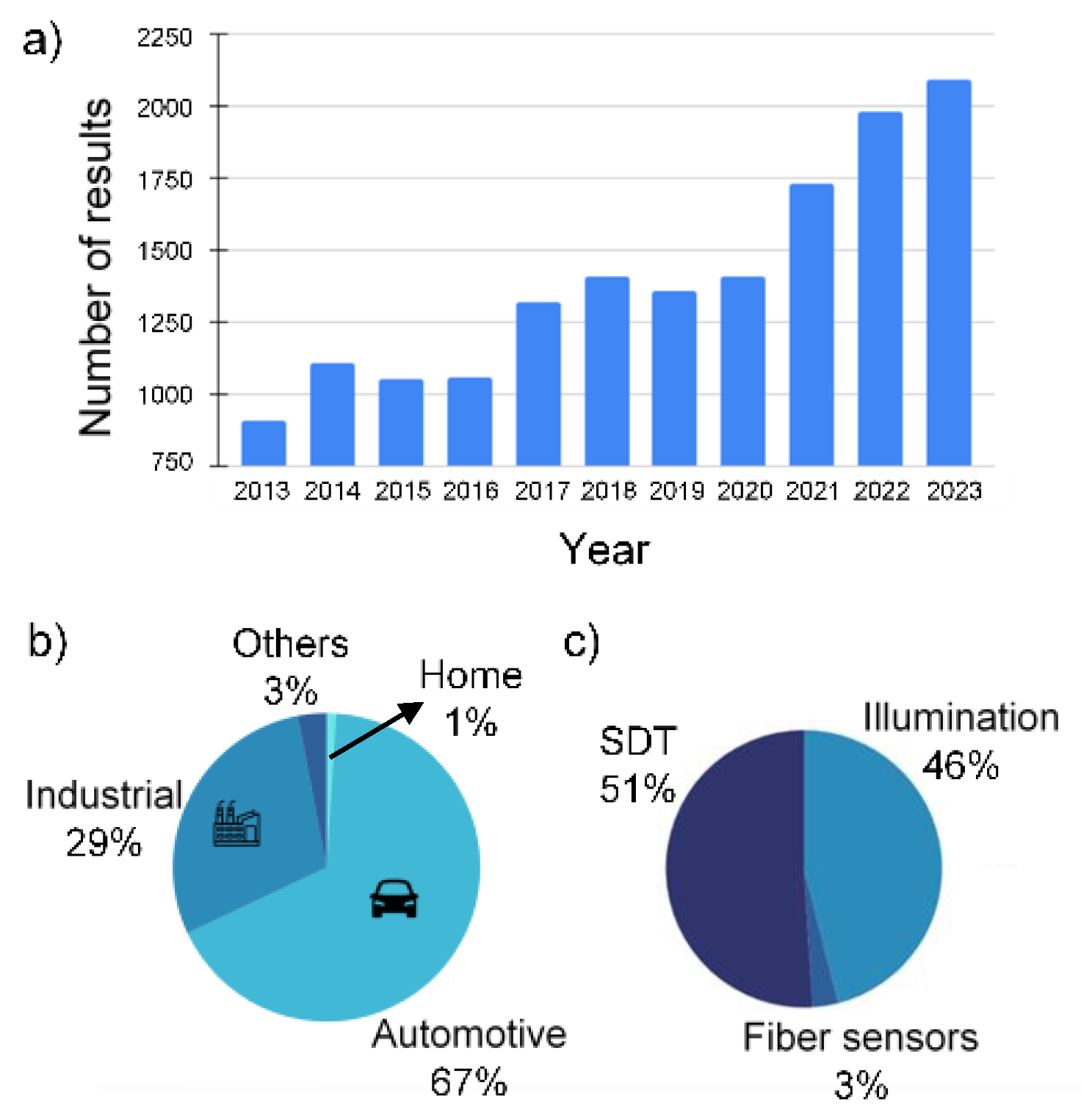
The use of POFs in sensing is increasing and its field of application is expanding. There are numerous benefits of polymer fibers, including lightweight, high flexibility, biocompatibility, resistance to electromagnetic interference, dielectric structure, suitable for performing direct and real-time optical measurements. Polymer optical fibers can find application in some environments not suited for electric conductors and electronic components [7], due to their immunity to high electric and magnetic fields (Figure 1b). POFs find applications in medicine, e.g. in photodynamic therapy (PDT) or optogenetic stimulation [8], and optical fiber sensing. Polymer optical fibers are also suitable for portable handheld sensors that eliminate requirement to gather samples on-site and conduct analysis in a laboratory setting. A simple optoelectronic sensor requires only a source of optical radiation (e.g. an LED), a fiber and a photodetector followed by a microcontroller with a display [9]. However, the applications of POFs are mainly focused on short-distance transmission and illumination rather than on the development of new sensors (Figure 1c). New biodegradable materials for POFs are constantly being developed based on biodegradable materials [10]. This is not only to the advantage of the natural environment, but also to benefit of an increasing number of new applications. A biodegradable fiber can be implanted into a patient’s body for the duration of the treatment in the bodily tissues and to degrade naturally in a harmless manner after the treatment has been completed [11].
The range of materials that can be used in polymer optical fibers for sensing applications is continually expanding. At present, the most commonly used material for polymer optical fiber is PMMA [2], whose the main advantage is a relatively low cost. The alternatives to PMMA are low-loss amorphous fluorinated polymers (CYTOP) [12], water absorption-resistant materials like cyclic olefin polymers (TOPAS and ZEONEX) [13,14], materials with excellent impact strength like polycarbonate (PC) [15], which can be printed in 3D and biodegradable materials such as poly-d,l-lactic acid (PDLLA) [10]. New materials are being developed for sensing POFs in order to improve their optical and mechanical properties, to provide resistance to selected chemical compounds, in order to enhance the operating temperature range or to tailor the biodegradability of the POFs.
Several types of optical fiber sensors using diverse operation principles can be implemented using polymer optical fibers. In particular, sensors reported in the literature use intensity [16], interferometry [17], Bragg gratings [18] and optical time domain reflectometry [19]. The class of intensity optical fiber sensors known as U-shape sensors was selected for this review, as it apparently has the most diverse range of POF types that can be employed as its sensing elements.
The purpose of this paper is to review polymer materials that can be used in the sensing part of U-shape optical fiber sensors. The principles of operation of U-shape sensors are outlined in Section 2. Following, the applications of U-shape optical fiber sensors are briefly discussed in Section 3. The review of polymer materials for sensing POFs is presented in Section 4, while Section 5 contains conclusions and a brief discussion.
2. POF U-Shape Sensor Principles
An optical fiber consists of a core, usually with a circular cross-section, where light is guided, embedded in a cladding, as shown schematically in Figure 2. Both core and cladding are made from isotropic dielectric materials having low attenuation of light to be transmitted.
Propagation of light in an optical fiber depends on the diameter of the core diameter of the cladding as wells as on the refractive indices of the core and cladding materials, n1 and n2 respectively.
An isotropic material’s refractive index (RI) is determined by the ratio of velocity of light in vacuum to the velocity of light in the material [20], i.e.:
where c – velocity of light in vacuum, v –velocity of light in the material.
A wave incident on the end face of the fiber becomes a guided wave when its direction of propagation is within the cone of acceptance, as shown in Figure 2. Otherwise, it becomes an unguided or evanescent wave (EW). The acceptance angle θ of the fiber is defined as:
where NA is the numerical aperture of the fiber, defined as:
where n1 – refractive index of the core, n2 – refractive index of the cladding [21]. For the fiber to operate properly, n1 must be greater than n2 in order to preserve the phenomenon of total internal reflection. Numerical aperture is used as a measure of light-gathering properties of the fiber. The greater the NA, the greater the acceptance angle θ and the wider the acceptance cone, allowing more waves into the fiber, as shown in Figure 2.
Any wave propagating in the fiber has to satisfy its characteristic equation [22]. The number of its solutions is finite, and each solution is called a mode. The quantity of modes propagating in a fiber depends on the radius a of its core, the refractive indices n1 and n2 of its core and cladding, respectively, and the wavelength λ of light propagating in the fiber.
For given refractive indices n1 and n2 it is possible to reduce the radius of the core a to a value for which only one mode propagates in a fiber for any wavelength λ longer than the cutoff wavelength λc given by [21]:
A fiber in which only one mode can propagate in the operating wavelength range of the fiber is called a single-mode fiber, while a fiber in which several modes can propagate in the operating wavelength range is called a multi-mode fiber.
Attenuation restricts the distance a signal can propagate through the fiber before the optical power deteriorates excessively. Several factors can cause attenuation, like material absorption, scattering in material or bending [21]. Attenuation coefficient α, expressed usually in dB/km or dB/m is defined as:
where L – distance, Pin – input power, Pout – output power.
Most of U-shape sensors are intensity sensors, operating using measurand-induced intensity changes. These changes may be caused either by changing the propagation conditions in the fiber, or by absorption of the evanescent field, as described in Section 2.1 and Section2.2, respectively.
2.1. Sensing with Propagation Conditions in the Fiber
Light propagating in an unperturbed POF is attenuated according to (5). However, when a section of cladding is removed and replaced with another liquid or solid material that exhibits little absorption, the propagation conditions in that fiber segment start to depend on the refractive index of that material [23]. In particular, when its refractive index is greater than that of the cladding, the NA decreases (c.f. (3)), some light becomes unguided and is coupled to the outside medium. The amount of light coupled out depends on the length of the section. Additionally, the bending of the fiber into an U shape introduces additional changes in the propagation conditions, making the sensor more sensitive. Sensitivity can be also tailored by tapering [24] or polishing [25] the core. Coatings whose thickness is well below the wavelength of the light propagating in the fiber can be applied on the core to protect it from the environment in which the sensor operates without substantially changing the properties of such sensors.
2.2. Sensing with Evanescent Field
When light is transmitted in an optical fibre, part of its energy, called evanescent wave, is propagating in the cladding. When EW extends into the medium surrounding the core, its amplitude E decays exponentially:
where, E0 is the amplitude of the field at the surface of the core, z is the distance from the surface of the core, and dp is the penetration depth, that can be expressed as:
where: λ is the wavelength in vacuum, θ is the incident light angle [26].
Interaction between the evanescent wave and the substance surrounding the fiber takes place when a significant part of energy propagating in this wave extends into that substance. This interaction can be promoted by a partial or complete removal of the cladding of the fiber, as shown in Figure 3a. Increased evanescent wave power enhances sensitivity, by provides more evanescent waves to interact with the surrounding medium [27]. As the energy loss of the evanescent wave depends in particular on the length of the sensing fiber section and on the refractive index, and absorption coefficient of the surrounding substance, changes in the two latter quantities can be detected by measuring the intensity of light exiting the sensing fiber section.
2.3. U-Shape Fabrication
Flame or other heat source can be used to soften the optical fiber and bend it into a suitable shape that will be retained after it cools down. Parameters such as the bend radius or angle could be hard to repeat, so a mold is proposed, e.g. in the form of a glass tube [28] or curved blunt needles [29]. In addition, the glass tube can then be filled with glue to help retain the shape of the fiber and form a structural package for the sensor. Another method that can help control the parameters of bending is to use heated metal molds [30]. In general, it can be stated, that the use of thermoplastic polymers as material bases for U-shaped fiber optic sensors is well justified regarding to the fundamental issue of forming the shape of the active part of the sensor. The properties of the materials in this group allow for a relatively straightforward execution of the bending. Also it is possible to achieve shape retention by heat treatment which relaxes the internal stresses and decreases the tendency for fiber re-straightening.
Cladding removal can be performed mechanically, by stripping and polishing, or using chemical agents, such as acetone or ethyl acetate [9] depending on the materials of core and cladding.
Fiber Bragg Gratings (FBG) can be used to aid and modify the performance of U-shape fiber optic sensors [31]. The FBG is a type of optical filter that reflects specific wavelengths of light and transmits all others in an optical fiber. It is created by inducing a periodic variation of refractive index changes within the core of an optical fiber, which leads to constructive interference of light at the Bragg wavelength and destructive interference at other wavelengths. FBG is often used as a sensing element in various applications such as temperature, pressure, strain, and vibration sensing. Combination of U-shape fiber and FBG exhibits an increase in signal power while grating being in stretching mode and therefore located on the outer part of the bent fiber [32].
3. Applications of U-Shape POF
U-shape POF sensors find applications in various fields, such as biosensing, chemical sensing and physical sensing [33,34]. The U-shape design of the fibre allows for a larger sensing area and increased sensitivity compared to straight fiber sensors.
An U-shaped fiber optic sensor can be used to identify variations in the refractive index of its surrounding environment. The probe can be dipped into a solution with varying refractive index, typically below the RI of the core of the fiber. This sensing principle can be used for measurement of all quantities that modify the RI of the solid or liquid material surrounding the core of the sensing fiber.
In particular, U-shape sensors can be applied to measure temperature and find the location of the heat source [35]. In chemical sensing they can be employed for measurement of water salinity [36], sugar or alcohol concentration in water, or detection of contaminants in water. More advanced applications of U-shape sensors rely on functionalization of the surface of the core of the sensing fiber. An example sensor used fiber whose surface was functionalized with silver nanoparticles and was tested in an alcohol solution [37]. U-shape sensors in biological applications were used for the detection of bacteria in tap water, with the sensing region tapered to achieve a higher sensitivity [24].
Immunosensors were also demonstrated. In particular, biosensors with U-shape were fabricated for detection of copper ions in blood serum [38]. The sensors were functionalized with immunoglobulin G as the receptor molecule and copper concentration measurement was performed by measuring the change in absorbance. An immunobiosensor of chikungunya protein was demonstrated using a system functionalized with gold nanoparticles and an antibody as a label for detection, relying on the measurement of absorbance change [39]. For bacterial detection U-shape fiber sensors were functionalized with antibodies and were tested for E. coli detection [40].
Constructing a sensor with a new polymer material can lead to the creation of novel sensors and finding of new applications. The development of technologies for functionalization and geometric modification of fiber optics offers numerous possibilities for modification and optimization of U-shape sensors performance.
4. Materials for Polymer Optic Fibers
Polymer optical fibers (POFs) are used as an alternative to glass optical fibers (GOFs). Advantages of POFs include low-attenuation window in the visible wavelength range (400−700 nm) and flexibility, especially in fibers of larger diameter (∼1 mm). The main criteria for the selection of material for the optical fiber are the refractive index, melting point, proper flexibility, mechanical strength and suitable resistance to the factors in the environment where the sensors operate.
4.1. Conventional POFs
POFs can be manufactured from a wide range of polymeric materials, some of which are listed below:
- Conventional POFs (PMMA, polycarbonate (PC), polystyrene (PS)),
- Hydrogel Optical Fibers (HOFs),
- Bio Polymer Optic Fibers (BIOPOFs),
- High Performance Polymers (HPP),
- UV curable and sol-gel based acrylics, water-based polymers and urethanes.
PMMA also known as “Plexiglas” is the most commonly chosen material for POF fabrication and is widely available commercially [42]. PMMA is resistant to water and oil, but under humid conditions PMMA tends to absorb water up to 2% [43]. The refractive index of PMMA is 1.49 [44]. The PMMA material performs well in the visible spectrum with the optical windows in the range of 400-700 nm and in infrared ~850nm. Standard working temperature ranges from –40 to +85 °C, and at 130°C the material approaches its melting point [44]. For high temperature applications, the material used for the optical fiber must be capable of function at temperatures exceeding 100°C. PMMA can be used in 3D printing, however the use of this technology results in high transmission losses experienced by the final product [45]. The tensile strength reaches approximately 76 MPa [46]. The material exhibits biocompatibility [47] and good compatibility with the human tissue [48]. After 15 days of PMMA exposure on 40W UV lamp (290-315nm) the transmittance reduction of 5% occurs [49].
Commercially, standard PMMA POF is multi-mode, with high numerical aperture (NA) (~0.5), which makes it easier to connect to low-cost sources and detectors. The most popular size of 1 mm is dominant on the market, but different sizes are also available, ranging from 0.25 mm to 1 cm. The attenuation profile of typical PMMA fiber is shown in Figure 4a. The most common fiber cladding material is modified (fluorinated) PMMA polymer, which has lover refractive index than the core (RI ≈ 1.35). In POF the cladding represents usually around 2-5% of the fibre diameter.
Crystallizable polymers contain both crystalline and amorphous regions, but amorphous polymers are favoured as a core material due to their uniform density. PC-based optical fibers have very similar RI to the PS (1.58) and lower optical losses than PS, however, higher compared to PMMA. PC also exhibits greater heat resistance. The higher glass transition temperature (Tg=150°C) allows PC to withstand a high operating temperature (up to 130°C) [46].
The blend of optical and mechanical attributes of PC makes it suitable for optical fiber applications. POFs made of polycarbonate have relatively large NA, as compared to other POFs, which can be explained by high refractive index of PC. The PC fibres provide efficient short range optical transmission within visible range. The absorbance characteristic of the solid-core PC shown in Figure 4b suggest more absorbance between 800 and 900 nm. The average tensile strength is also similar to PMMA material 62.7-64.5 MPa [50]. One disadvantage of PC is the tendency of its yellowing due to aging and losing transmission quicker than PMMA [47]. The relative transmission drops with aging several times quicker than in PMMA fibres. Material can be used for 3D printing, also for fiber fabrication [51]. The PC material can be used for the fibre core fabrication in various shapes [52]. Multi-mode PC polymer optical fibers offer easier coupling with light transmitters and receivers using economical connectors [53]. Currently fiber optics made of PC, have been replaced on the market by POF made of PMMA.
Polystyrene (PS) material is suitable for making optical fibers, but its optical properties are inferior compared to the mentioned synthetic polymers fibers. Hitherto there has been no reason to replace the PMMA POFs by PS fibers.
An U-shaped PMMA POF biosensor coated with gold has been developed for the detection of E. coli. The POF functions as a refractive index sensor without the necessity of cladding removal. U-shaped probes coated with gold with thicknesses of up to 18 nm exhibit behavior comparable to uncoated probes, with bending loss being the primary sensing mechanism. Probes coated with thin layer of gold, below 50 nm, are ineffective for that sensing application. In contrast, probes coated with 70 nm and 100 nm of gold demonstrate the predominance of surface plasmon resonance (SPR) effects, enabling the biosensor to detect bacterial concentrations as low as 1.5x10³ CFU/mL [54].
M. Lomer et al. fabricated a refractometric sensor based on PMMA POF for measuring power losses in liquids. The operating principle relies on induced losses occurring in the transition region of a curved side polished POF fiber [25]. Ara Rashid et al. presented the POF fiber composed of a PMMA core and a fluorinated polymer clad with refractive index of 1.49 and 1.41 respectively. They tested the sensor for the E. coli detection [55]. Shumin Wang et al. developed a double side-polished U-shaped POF sensor made of PMMA for RI application. Sensor promises great potential in liquid RI measurement from 20 to 50°C [30]. A PMMA based U-shaped POF sensor has been applied in real-time monitoring systems and utilized for detecting scale deposition in hot spring water sources [56].
4.2. Hydrogel Optical Fibers (HOFs)
Hydrogels offer versatility in adjusting the optical and mechanical properties of the material by manipulating the polymer to water ratio, resulting in transparency, flexibility, and stability. [51]. As common HOFs fabrication raw materials, agarose, alginate, gelatine, cellulose derivatives, PVA, poly(ethylene glycol) (PEG), PEGDA, P(AAm-co-EGDA), and polyacrylamide (PAAm) [57].
For poly(ethylene glycol) (PEG) based hydrogel fiber the refractive index can be changed by precursors concentration. Reported PEG fiber with alginate hydrogel clad has low-loss light guiding (<0.42 dB/cm) over the entire visible spectrum [58]. Obtained core size in range of 250-1000 µm, and a different size of cladding depends on the number of layers. Hydrogel fiber can be soft, have low cytotoxicity and good selling stability, which make them suitable for use in photomedical applications in tissues, like photothermal and photodynamic therapy [59].
Currently, PEDGA is a widely studied synthetic polymer material due to its broad range of applications, attributed to its key properties such as nontoxicity, softness, and suitability for use in implantable devices. This material is particularly well-suited for biomedical applications due to its simple gelation process with divalent cations [57].
The fibers derived from cellulose-based materials exhibit renewability, biocompatibility, and biodegradability. The value of 1.6 dB/cm attenuation coefficient was measured at 637 nm for reported fibers mode of carboxymethyl cellulose (CMC) hydrogel without cladding. These optical fibers found successful applications in touch sensing and monitoring respiratory rates. Furthermore, high-speed signal transmission at 150 Mbit/s was demonstrated over short distances using CMC fibers [60].
The poly(D,L-Lactic Acid) (PDLLA) is another suitable natural material for the relatively fast degradation required POF applications. Degradation over time has been reported for fibers made from PDLLA material. A decrease of over 80% was observed within 3 months. Similar to other degrading optical fibers, the degradation time depends on parameters such as the material’s thickness and morphology. Larger diameter fibres tend to degrade faster than those with smaller diameters. Optical parameters for PDLLA fibers are: attenuation 0.16 dB/cm at 650 nm and 0.13 dB/cm at 850 nm [11].
Biodegradable POF with faster degradation time and improved transmission properties have been reported. By creating a fiber with a core made from poly(D,L-lactic-co-glycolic acid) and a cladding made from poly(D,L-lactic acid). The lowest attenuation 0.26 dB/cm at 950 nm and weight loss of 91% over 3 months was achieved [61].
Hydrogel optical fibers (HOFs) exhibit several advantages, including flexibility, low cytotoxicity, and excellent structural stability. However, their primary limitation is high optical attenuation, which restricts effective light transmission to few tens of centimeters. This poses a significant challenge, particularly for applications requiring longer transmission distances. To address this issue, ongoing research is focused on the development and implementation of novel materials that can enhance the optical properties of HOFs.
4.3. Bio Polymer Optic Fibers (BIOPOFs)
The environmental factors have attracted cellulose and its derivatives as new biopolymers for BIOPOFs applications [62]. Cellulose has excellent biocompatibility and can be blended with another biopolymer of spider silk which is also biocompatible and has shielding properties to make novel POF as a promising material in medical applications.
Due to optical characteristics, those materials exhibit promise for utilization in optoelectronic devices. Besides fiber fabrication, cellulose and its derivatives have found versatile applications including OLED technology, flexible touch displays and solar cells. [63]. Goudbut et al. developed a dual-core fiber structure with cellulose butyrate tubes as core and shell materials. This was achieved by utilizing two types of biodegradable cellulose with differing refractive indices, enabling the fabrication of the optical fiber. This approach leverages the refractive index contrast between the materials to guide light effectively, while maintaining biodegradability and environmental sustainability [64]. An optical fiber tailored for water sensing applications was fabricated through the direct processing of cellulose, as reported by Orelma et al. Regenerated cellulose was dissolved in the ionic liquid, coagulated in water to form a regenerated fiber, and subsequently coated with cellulose acetate. The resulting BIOPOFs exhibited minimal attenuation of 5.9 dB/cm at a wavelength of 1130 nm [10]. Cellulose based optical fibers have great potential, through their biocompatibility and low environmental impact, unfortunately research is still needed to improve optical properties [65].
Another notable biopolymer material is silk, which can be derived from silkworms or spiders [67]. An optical structure based on silk derived from silkworms was demonstrated by the group of Omenetto et al. The material exhibited toughness and excellent optical transparency in the visible range, with a transmittance of approximately 92% [66]. Furthermore, Parker et al. used silkworm silk protein hydrogels for bioprinting it on a borosilicate glass substrate with a lower refractive index than the silk protein fiber making waveguide [68]. These studies combined a similar approach of using surrounding media with lower refractive index.
4.4. High Performance Polymers POF (HPPPOFs)
Perfluorinated polymer material known as CYTOP can operate in 200 to 2000 nm and achieves ~0.2 dB/m attenuation [11]. This makes it a better material for transmission of telecommunication signals than PMMA (Figure 4d). CYTOP refractive index equals 1.34 at 584 nm [69], tensile strength of 41-49 MPa with practically no water absorption [70]. Fiber made with CYTOP is “GigaPof” manufactured by Chromis Fiberoptic in the USA. The CYTOP material has better transmittance compared to PMMA. CYTOP polymer was developed aimed at mitigating the limitations imposed by molecular vibrations in the near-infrared (NIR) region. Notably, the C-H and O-H bond vibrations, which typically appear within the 1100-1700 nm range, pose a significant challenge for applications requiring high transparency in this spectral window. To overcome this, researchers proposed substituting hydrogen atoms with heavier isotopes such as fluorine in CYTOP structure. This substitution effectively shifts the vibrational modes of the C-F bond toward longer wavelengths, thereby reducing their impact in the NIR range. As a result, CYTOP exhibits enhanced performance, expanding the potential applications of polymer optical fibers (POFs) in this critical spectral region [71]. Due to low refractive index the material presents low signal dispersion [72], which makes this material the most suitable for communication applications. For this reason, medium is mostly used for data transmission, but also in long array of sensors [73]. CYTOP in use as a sensor most often uses a fibre Bragg grating for measuring temperature, strain and humidity [74]. Subsequent applications are structural health monitoring, in mechanical and civil engineering, rehabilitation, robotics [12].
Another example of worthy material for use in optic fibres is the Cyclo Olefin Polymer (Zeonex). It has good transparency and signal loss is relatively low in the visible range. Compared to PMMA, it exhibits a very low affinity to water, at least 30 times, but poor resistance to oils. The tensile strength for Zeonex is in the range of 63-70 MPa [75]. For fiber made of Zeonex a minimum recorded loss is 2.34 dB/m at 690 nm, in near infrared propagation loss increases significantly [76]. The refractive index is equal to 1.52 [77]. The Zeonex material is proper for multicore fibers and other high-quality microstructure fabrication in the fiber. Although a single-mode fiber can be fabricated from Zeonex, it exhibits higher minimum losses, recorded at 3 dB/m at 796 nm. The maximum operating temperature of 123°C was recorded [78].
A material similar to Zeonex is Topas. The main difference between those two materials can be seen in terms of their optical loss within visual and NIR range (Figure 4c), which suggests that fiber loss for Topas is higher in the visible range. Additionally, as compared to PMMA, Topas has lower water absorption <0.01%. Some materials of the Topas group are resistant to short-term high temperature exposure of up to 170 °C, but the melting point is above 190 °C. The refractive index of Topas material is 1.53 and the tensile strength for Topas is in the range of 58-63 MPa [13].
The single mode step index fibre fabricated with a Topas core and Zeonex cladding has a loss of 4.55 dB/m at 850nm. Other single mode step index POF available commercially are very lossy (500db/m at 850 nm) [79].
A U-shaped fiber optic sensor for humidity measurement in the range of 15–85% RH has been presented by Zhao et al. The sensor was fabricated by coating a single-mode optical fiber bent into a U-shape with a layer of polyvinyl alcohol (PVA). The sensor achieved a sensitivity of 318 pm/%RH [80]. Another authors attempt to improve the sensor by adding graphene quantum dots (GQDs) to the humidity sensor probe. The electrospun optical fiber coated with PVA–GQDs film onto the surface of an U-shaped optical fiber has been explored, with experimental results showed the average sensitivity of transmission to -0.131dB/%RH [81].
The functionalization of PMMA core U-shape POF fibers with Polyethyleneimine (PEI) enables the release of amines for antibody fixation. By bending, the sensitivity was increased by contact between the curved sensor component and the biological sample is achieved. The sensor formed this way can be then used with the Evanescent Field technique for sensing. Escherichia coli concentrations of 108 CFU/mL and 104 CFU/mL were detected by this biosensor using the designed optoelectronic data collecting device [82].
Chuanxin Teng et al. created a double-sided polished U-shape POF-based SPR sensor based on polydimethylsiloxane (PDMS) film, the sensor was used to measure temperature and RI at the same time [83].
4.5. Other POFs (UV Curable and Sol-Gel Based Acrylics, Water-Based Polymers and Urethanes)
UV curable, sol-gel based acrylics (urethane acrylates, silicon acrylates, fluorinated acrylates and methacrylate’s) and water-based polymers (urethanes, rubbers based systems) has an important potential for POF applications in future. A. Evertz et al. [84] has developed a UV-curable and a dip-coating technique (optically compatible coating, RI=1.4 (Fospia/Efiron)) to apply cladding material onto previously extruded POF cores (PMMA, RI =1.49) with diameters of about 16 µm. They also mentioned that at least 20 µm diameter is needed for a stable and continuous process. The best measured attenuations were determined as 3 dB/m for fibers with a core diameter of 46 µm. Rune Inglev et al. developed POF sensor for the dissolved oxygen sensing by phase fluorometry [85]. The sensing matrix (luminophore platinum-octa ethyl porphyrin and the luminophore coumarin to increase the brightness) is applied as a film on the PMMA fiber end-surface. This approach can be extended to other polymers and luminophores. UV polymerization fabrication method also used for polymer composite based optical fiber sensor fabrication [86].
4.6. Comparison of Several Parameters Corresponding to POFs of Different Core Compositions
Fiber optics are made with the core composition listed in the Table 1, but to make an U-shape sensor not all materials will be suitable. Based on optical losses, the best choice seems to be CYTOP. Unfortunately, its low refractive index is associated with a low numerical aperture, which causes a low number of propagated mods. CYTOP is well suited for communication applications, but not for making U-shape sensors which are based on propagation loss in sensing area. On the other hand, choosing a PDLLA with losses of 11 dB/m may prove to be a problem. Losses at this level necessitate making the sensor as short as possible, using a high-power source and a sensitive detector. The high attenuation of PEGDA fibers means that light can only be guided for a few tens of centimeters.
Zoenex and PMMA have similar parameters, when it comes to refractive index and tensile strength, but optical loss for PMMA is a few fold lower. Therefore, PMMA seems to be the most suitable material for the manufacture of U-shape POF sensor. An additional advantage is that the use of PMMA for POF is the most popular [87]. The ranking of all mentioned materials based on their properties (from 1 to 5) is shown in Figure 5, where a higher rank indicates a higher property value. This representation allows for a straightforward comparison of these materials in terms of their potential applications.
5. Conclusions
Polymer Optical Fibers offer numerous benefits in sensing applications. In particular, their refractive index can be tailored to the needs of application in a relatively broad range while their size can be also varied. Their flexibility and ability of some POFs to be produced using additive manufacturing techniques, offer greater freedom in designing the sensing fiber section. Biocompatibility and biodegradability of selected POF materials, such as PMMA and PDLLA, facilitates their use in medical applications. Properly selected POFs are also able to operate in a relatively wide range of environmental conditions. POFs also provide numerous opportunities for geometrical modification or fabrication with additional layers of functional coatings.
In most of the cases light can be easily coupled into POFs. This makes it possible to work with low-cost electronic components such as LEDs and photodiodes. The sensor created with POFs allows near real-time measurements. New materials for fiber fabrication are constantly being engineered, to achieve improved optical, chemical and mechanical properties. Through the variety of materials, fiber optics can be used in a variety of conditions, such as environment measurement or in biological tissues.
Acknowledgments
This work was supported by DS programs of Faculty of Electronics, Telecommunications and Informatics of Gdańsk Tech for the support. Financial support of these studies from Gdańsk University of Technology by the 14/1/2024/IDUB/III.4.1/Tc grant under the TECHNETIUM Talent Management Grants program, as well as by the COST action CA21159 is gratefully acknowledged.
References
- Kallweit, J.; Pätzel, M.; Pursche, F.; Jabban, J.; Morobeid, M.; Gries, T. An Overview on Methods for Producing Side-Emitting Polymer Optical Fibers. Textiles 2021, Vol. 1, Pages 337-360 2021, 1, 337–360. [CrossRef]
- Chu, J.R.; Zhong, L.S.; Wen, X.M.; Xu, C.X. Study on Surface Fluorinating for Reducing Attenuation of Polymethyl Methacrylate Polymer Optic Fiber. J Appl Polym Sci 2005, 98, 2369–2372. [CrossRef]
- Coring SMF-28 Product Information Available online: (https://www.corning.com/media/worldwide/coc/documents/Fiber/product-information-sheets/PI-1424-AEN.pdf) (accessed on 7 February 2024).
- Chu, F.; Yang, J. Coil-Shaped Plastic Optical Fiber Sensor Heads for Fluorescence Quenching Based TNT Sensing. Sens Actuators A Phys 2012, 175, 43–46. [CrossRef]
- Xue, P.; Wu, B.; Bao, H.; Zheng, J. Screw-Shaped Plastic Optical Fibers for Refractive Index Sensing. IEEE Sens J 2020, 20, 5237–5242. [CrossRef]
- Google Scholar Available online: https://scholar.google.com/ (accessed on 27 February 2024).
- Habel, W.R.; Krebber, K. Photonic Sensors Review Fiber-Optic Sensor Applications in Civil and Geotechnical Engineering. Photonic Sensors 2011, 1, 268–280. [CrossRef]
- Cochrane, C.; Mordon, S.R.; Lesage, J.C.; Koncar, V. New Design of Textile Light Diffusers for Photodynamic Therapy. Mater Sci Eng C Mater Biol Appl 2013, 33, 1170–1175. [CrossRef]
- Gowri, A.; Rajamani, A.S.; Ramakrishna, B.; Sai, V.V.R. U-Bent Plastic Optical Fiber Probes as Refractive Index Based Fat Sensor for Milk Quality Monitoring. Optical Fiber Technology 2019, 47, 15–20. [CrossRef]
- Orelma, H.; Hokkanen, A.; Leppänen, I.; Kammiovirta, K.; Kapulainen, M.; Harlin, A. Optical Cellulose Fiber Made from Regenerated Cellulose and Cellulose Acetate for Water Sensor Applications. Cellulose 2020, 27, 1543–1553. [CrossRef]
- Gierej, A.; Vagenende, M.; Filipkowski, A.; Siwicki, B.; Buczynski, R.; Thienpont, H.; Vlierberghe, S. Van; Geernaert, T.; Dubruel, P.; Berghmans, F.; et al. Poly(D,L-Lactic Acid) (PDLLA) Biodegradable and Biocompatible Polymer Optical Fiber. Journal of Lightwave Technology, Vol. 37, Issue 9, pp. 1916-1923 2019, 37, 1916–1923. [CrossRef]
- Theodosiou, A.; Kalli, K. Recent Trends and Advances of Fibre Bragg Grating Sensors in CYTOP Polymer Optical Fibres. Optical Fiber Technology 2020, 54, 102079. [CrossRef]
- TOPAS® COC Cyclic Olefin Copolymer Available online: https://topas.com/sites/default/files/TOPAS_Product-3.08.21.pdf (accessed on 13 December 2023).
- Zeonex Product Information Available online: (https://www.zeon.co.jp/en/business/enterprise/resin/pdf/200323391.pdf) (accessed on 7 February 2024).
- Stajanca, P.; Markos, C.; Nielsen, K.; Bang, O.; Stefani, A.; Krebber, K.; Fasano, A.; Woyessa, G.; Rasmussen, H.K. Fabrication and Characterization of Polycarbonate Microstructured Polymer Optical Fibers for High-Temperature-Resistant Fiber Bragg Grating Strain Sensors. Optical Materials Express, Vol. 6, Issue 2, pp. 649-659 2016, 6, 649–659. [CrossRef]
- Cennamo, N.; Arcadio, F.; Marletta, V.; Baglio, S.; Zeni, L.; Ando, B. A Magnetic Field Sensor Based on SPR-POF Platforms and Ferrofluids. IEEE Trans Instrum Meas 2021, 70. [CrossRef]
- Statkiewicz-Barabach, G.; Mergo, P.; Urbanczyk, W. Bragg Grating-Based Fabry–Perot Interferometer Fabricated in a Polymer Fiber for Sensing with Improved Resolution. Journal of Optics 2016, 19, 015609. [CrossRef]
- Hu, X.; Chen, Y.; Gao, S.; Min, R.; Woyessa, G.; Bang, O.; Qu, H.; Wang, H.;; Caucheteur, C. Direct Bragg Grating Inscription in Single Mode Step-Index TOPAS/ZEONEX Polymer Optical Fiber Using 520 Nm Femtosecond Pulses. Citation 2022, 14, 1350. [CrossRef]
- Dengler, S.A.; Roseeu, R. V.; Luber, G.M.; Ziemann, O.; Engelbrecht, R.; and Schmauss, B. “Performance Evaluation of Reference Reflections in Polymer Optical Fibers for Strain Sensing,” in 27th International Conference on Optical Fiber Sensors, Technical Digest Series (Optica Publishing Group, 2022).
- Senior, J.M. Optical Fiber Communications Principles and Practice Third Edition Optical Fiber Communications Optical Fiber Communications Principles and Practice; 2009;
- Hui, R. Optical Fibers. Introduction to Fiber-Optic Communications 2020, 19–76. [CrossRef]
- Saleh, B.E.A.; Teich, M.C. Fundamentals of Photonics 3rd Edition Part I: Optics Part II: Photonics (Wiley Series in Pure and Applied Optics, 2019). 2019, 1520.
- Patil, J.J.; Ghosh, A. Intensity Modulation Based U Shaped Plastic Optical Fiber Refractive Index Sensor. 2022 6th International Conference on Trends in Electronics and Informatics, ICOEI 2022 - Proceedings 2022, 18–24. [CrossRef]
- Beres, C.; de Nazaré, F.V.B.; de Souza, N.C.C.; Miguel, M.A.L.; Werneck, M.M. Tapered Plastic Optical Fiber-Based Biosensor – Tests and Application. Biosens Bioelectron 2011, 30, 328–332. [CrossRef]
- Lomer, M.; Galindez, C.A.; Quintela, M.A.; Quintela, A.; Mirapeix, J.; Lopez-Higuera, J.M. Refractometric Sensor Based on Induced Losses in the Region of Transition from a Curved Side-Polished POF Fiber. 19th International Conference on Optical Fibre Sensors 2008, 7004, 70045H. [CrossRef]
- Felsen, L.B., “Evanescent waves”, J. Opt. Soc. Am. 66, 751-760 (1976). [CrossRef]
- Tan, A.J.Y.; Ng, S.M.; Stoddart, P.R.; Chua, H.S. Theoretical Model and Design Considerations of U-Shaped Fiber Optic Sensors: A Review. IEEE Sens J 2020, 20, 14578–14589. [CrossRef]
- Chen, K.C.; Li, Y. Le; Wu, C.W.; Chiang, C.C. Glucose Sensor Using U-Shaped Optical Fiber Probe with Gold Nanoparticles and Glucose Oxidase. Sensors 2018, Vol. 18, Page 1217 2018, 18, 1217. [CrossRef]
- Memon, S.F.; Wang, R.; Strunz, B.; Chowdhry, B.S.; Pembroke, J.T.; Lewis, E. Novel Corrugated Long Period Grating Surface Balloon-Shaped Heterocore-Structured Plastic Optical Fibre Sensor for Microalgal Bioethanol Production. Sensors 2023, Vol. 23, Page 1644 2023, 23, 1644. [CrossRef]
- Wang, S.; Zhang, D.; Xu, Y.; Sun, S.; Sun, X. Refractive Index Sensor Based on Double Side-Polished U-Shaped Plastic Optical Fiber. Sensors 2020, Vol. 20, Page 5253 2020, 20, 5253. [CrossRef]
- Viegas, D.; Abad, S.; Santos, J.L.; Ferreira, L.A.; Araújo, F.M. Non-Terminal Miniature Fiber Bragg Grating Temperature Probe Based in a u-Shape Lossless Taper. Meas Sci Technol 2010, 21, 094002. [CrossRef]
- Leffers, L.; Locmelis, J.; Bremer, K.; Roth, B.; Overmeyer, L. Polymer Optical Fibre Bend Sensor Based on Eccentrical Bragg Gratings. Conference on Lasers and Electro-Optics (2021), paper STu2F.8 2021, STu2F.8. [CrossRef]
- Tan, A.J.Y.; Ng, S.M.; Stoddart, P.R.; Chua, H.S. Trends and Applications of U-Shaped Fiber Optic Sensors: A Review. IEEE Sens J 2021, 21, 120–131. [CrossRef]
- Jin, Y.; M Granville, A. Polymer Fiber Optic Sensors – A Mini Review of Their Synthesis and Applications. J Biosens Bioelectron 2016, 07. [CrossRef]
- Yee Tan, A.J.; Seng Ung, K.; Ng, S.M.; Stoddart, P.R.; Chua, H.S. Refractive Index, Temperature, and Heat Source Origin Sensing with Dual U-Shaped Fiber Probes. 2021 IEEE International Conference on Sensors and Nanotechnology, SENNANO 2021 2021, 29–32. [CrossRef]
- Stupar, D.Z.; Bajić, J.S.; Joža, A. V.; Dakić, B.M.; Slankamenac, M.P.; Živanov, M.B.; Cibula, E. Remote Monitoring of Water Salinity by Using Side-Polished Fiber-Optic U-Shaped Sensor. 15th International Power Electronics and Motion Control Conference and Exposition, EPE-PEMC 2012 ECCE Europe 2012. [CrossRef]
- Song, H.; Zhang, H.; Sun, Z.; Ren, Z.; Yang, X.; Wang, Q. Triangular Silver Nanoparticle U-Bent Fiber Sensor Based on Localized Surface Plasmon Resonance. AIP Adv 2019, 9, 085307. [CrossRef]
- Chandra, S.; Dhawangale, A.; Mukherji, S. Hand-Held Optical Sensor Using Denatured Antibody Coated Electro-Active Polymer for Ultra-Trace Detection of Copper in Blood Serum and Environmental Samples. Biosens Bioelectron 2018, 110, 38–43. [CrossRef]
- George, A.; Amrutha, M.S.; Srivastava, P.; Sunil, S.; Sai, V.V.R.; Srinivasan, R. Development of a U-Bent Plastic Optical Fiber Biosensor with Plasmonic Labels for the Detection of Chikungunya Non-Structural Protein 3. Analyst 2021, 146, 244–252. [CrossRef]
- Wandemur, G.; Rodrigues, D.; Allil, R.; Queiroz, V.; Peixoto, R.; Werneck, M.; Miguel, M. Plastic Optical Fiber-Based Biosensor Platform for Rapid Cell Detection. Biosens Bioelectron 2014, 54, 661–666. [CrossRef]
- Lee, S. C. J. Discrete multitone modulation for short-range optical communications. Phd Thesis 1 (Research TU/e / Graduation TU/e), Electrical Engineering. Technische Universiteit Eindhoven. 2009. [CrossRef]
- Moslan, M.S.; Othman, M.H.D.; Samavati, A.; Salim, M.A.M.; Rahman, M.A.; Ismail, A.F.; Bakhtiar, H. Fabrication of Polycarbonate Polymer Optical Fibre Core via Extrusion Method: The Role of Temperature Gradient and Collector Speed on Its Characteristics. Optical Fiber Technology 2020, 55, 102162. [CrossRef]
- Beckers, M.; Schlüter, T.; Vad, T.; Gries, T.; Bunge, C.A. An Overview on Fabrication Methods for Polymer Optical Fibers. Polym Int 2015, 64, 25–36. [CrossRef]
- ESKA Polymer Optical Fiber Brochure Available online: https://fiberfin.com/custom/upload/File-1363646917.pdf (accessed on 7 February 2024).
- Zubel, M.G.; Fasano, A.; Woyessa, G.; Sugden, K.; Rasmussen, H.K.; Bang, O. 3D-Printed PMMA Preform for Hollow-Core POF Drawing.; The 25th International Conference on Plastic Optical Fibers, 2016.
- Ziemann, O.; Krauser, J.; Zamzow, P.E.; Daum, W. POF Handbook: Optical Short Range Transmission Systems. POF Handbook: Optical Short Range Transmission Systems, Wiley 2008, 1–886. [CrossRef]
- Pituru, S.M.; Greabu, M.; Totan, A.; Imre, M.; Pantea, M.; Spinu, T.; Tancu, A.M.C.; Popoviciu, N.O.; Stanescu, I.I.; Ionescu, E. A Review on the Biocompatibility of PMMA-Based Dental Materials for Interim Prosthetic Restorations with a Glimpse into Their Modern Manufacturing Techniques. Materials 2020, 13, 1–14. [CrossRef]
- Ali, U.; Karim, K.J.B.A.; Buang, N.A. A Review of the Properties and Applications of Poly (Methyl Methacrylate) (PMMA). 2015, 55, 678–705. [CrossRef]
- Monsores, K.G.D.C.; Silva, A.O. Da; De Sant’Ana Oliveira, S.; Rodrigues, J.G.P.; Weber, R.P. Influence of Ultraviolet Radiation on Polymethylmethacrylate (PMMA). Journal of Materials Research and Technology 2019, 8, 3713–3718. [CrossRef]
- MatWeb Material Property Data.
- He, R.; Teng, C.; Kumar, S.; Marques, C.; Min, R. Polymer Optical Fiber Liquid Level Sensor: A Review. IEEE Sens J 2022, 22, 1081–1091. [CrossRef]
- Zhao, Q.; Tian, F.; Yang, X.; Li, S.; Zhang, J.; Zhu, X.; Yang, J.; Liu, Z.; Zhang, Y.; Yuan, T.; et al. Optical Fibers with Special Shaped Cores Drawn from 3D Printed Preforms. Optik (Stuttg) 2017, 133, 60–65. [CrossRef]
- Moslan, M.S.; Othman, M.H.D.; Samavati, A.; Salim, M.A.M.; Rahman, M.A.; Ismail, A.F.; Bakhtiar, H. Fabrication of Polycarbonate Polymer Optical Fibre Core via Extrusion Method: The Role of Temperature Gradient and Collector Speed on Its Characteristics. Optical Fiber Technology 2020, 55, 102162. [CrossRef]
- Arcas, A. da S.; Dutra, F. da S.; Allil, R.C.S.B.; Werneck, M.M. Surface Plasmon Resonance and Bending Loss-Based U-Shaped Plastic Optical Fiber Biosensors. Sensors 2018, Vol. 18, Page 648 2018, 18, 648. [CrossRef]
- Rashid, A.R.A.; Hakim, A.A.N.; Yahaya, N.; Surani, A.H. U-Bent Polymer Optical Fiber (POF) for Escherichia Coli Detection. OPTOELECTRONICS AND ADVANCED MATERIALS-RAPID COMMUNICATIONS 14, 118–122.
- Okazaki, T.; Kamio, H.; Yoshioka, M.; Ueda, A.; Kuramitz, H.; Watanabe, T. U-Shaped Plastic Optical Fiber Sensor for Scale Deposition in Hot Spring Water. Analytical Sciences 2022, 38, 1549–1554. [CrossRef]
- Pires, R.A.; Pashkuleva, I.; Reis, R.L. Multifunctional Hydrogels for Biomedical Applications, Wiley, 2022.
- Choi, M.; Humar, M.; Kim, S.; Yun, S.H. Step-Index Optical Fiber Made of Biocompatible Hydrogels. Adv Mater 2015, 27, 4081–4086. [CrossRef]
- Chen, G.; Hou, K.; Yu, N.; Wei, P.; Chen, T.; Zhang, C.; Wang, S.; Liu, H.; Cao, R.; Zhu, L.; et al. Temperature-Adaptive Hydrogel Optical Waveguide with Soft Tissue-Affinity for Thermal Regulated Interventional Photomedicine. Nature Communications 2022 13:1 2022, 13, 1–9. [CrossRef]
- Jaiswal, A.K.; Hokkanen, A.; Kapulainen, M.; Khakalo, A.; Nonappa; Ikkala, O.; Orelma, H. Carboxymethyl Cellulose (CMC) Optical Fibers for Environment Sensing and Short-Range Optical Signal Transmission. ACS Appl Mater Interfaces 2022, 14, 3315–3323. [CrossRef]
- Gierej, A.; Filipkowski, A.; Pysz, D.; Buczynski, R.; Vagenende, M.; Dubruel, P.; Thienpont, H.; Geernaert, T.; Berghmans, F. On the Characterization of Novel Step-Index Biocompatible and Biodegradable Poly(D,L-Lactic Acid) Based Optical Fiber. Journal of Lightwave Technology 2020, 38, 1905–1914. [CrossRef]
- Reimer, M.; Mayer, K.; Van Opdenbosch, D.; Scheibel, T.; Zollfrank, C. Biocompatible Optical Fibers Made of Regenerated Cellulose and Recombinant Cellulose-Binding Spider Silk. Biomimetics 2023, Vol. 8, Page 37 2023, 8, 37. [CrossRef]
- Reimer, M.; Zollfrank, C.; Reimer, M.; Zollfrank, C. Cellulose for Light Manipulation: Methods, Applications, and Prospects. AdEnM 2021, 11, 2003866. [CrossRef]
- Godbout, N.; Guo, N.; Gao, Y.; Dubois, C.; Dupuis, A.; Skorobogatiy, M.; Lacroix, S. Prospective for Biodegradable Microstructured Optical Fibers. Optics Letters, Vol. 32, Issue 2, pp. 109-111 2007, 32, 109–111. [CrossRef]
- Reimer, M.; Van Opdenbosch, D.; Zollfrank, C. Fabrication of Cellulose-Based Biopolymer Optical Fibers and Their Theoretical Attenuation Limit. Biomacromolecules 2021, 22, 3297–3312. [CrossRef]
- Omenetto, F.G.; Kaplan, D.L. A New Route for Silk. Nature Photonics 2008 2:11 2008, 2, 641–643. [CrossRef]
- Mittal, N.; Jansson, R.; Widhe, M.; Benselfelt, T.; Håkansson, K.M.O.; Lundell, F.; Hedhammar, M.; Söderberg, L.D. Ultrastrong and Bioactive Nanostructured Bio-Based Composites. ACS Nano 2017, 11, 5148–5159. [CrossRef]
- Parker, S.T.; Domachuk, P.; Amsden, J.; Bressner, J.; Lewis, J.A.; Kaplan, D.L.; Omenetto, F.C. Biocompatible Silk Printed Optical Waveguides. Advanced Materials 2009, 21, 2411–2415. [CrossRef]
- CYTOPTM Technical Information - AGC Chemicals Europe Available online: https://www.agcce.com/cytop-technical-information/ (accessed on 13 December 2023).
- CYTOP® | Product Information | Fluoroproducts Business | AGC Chemicals Company Available online: https://www.agc-chemicals.com/jp/en/fluorine/products/detail/index.html?pCode=JP-EN-F019 (accessed on 13 December 2023).
- Koike,Y., Koike, K., “Optical Fibers”, in Polymer Science: A Comprehensive Reference, Elsevier (2012) 283-304. [CrossRef]
- Koike, Y. Fundamentals of Plastic Optical Fibers. Fundamentals of Plastic Optical Fibers 2014, 139–168. [CrossRef]
- Leal-Junior, A.G.; Theodosiou, A.; Díaz, C.R.; Marques, C.; Pontes, M.J.; Kalli, K.; Frizera, A. Simultaneous Measurement of Axial Strain, Bending and Torsion With a Single Fiber Bragg Grating in CYTOP Fiber. Journal of Lightwave Technology 2019, 37. [CrossRef]
- Nan, Y.-G.; Yazd, N.S.; Chapalo, I.; Chah, K.; Hu, X.; Mégret, P. Properties of Fiber Bragg Grating in CYTOP Fiber Response to Temperature, Humidity, and Strain Using Factorial Design. Sensors 2022, Vol. 22, Page 1934 2022, 22, 1934. [CrossRef]
- Zoetex Chemical Resistance Available online: (https://www.zeonex.com/pharmaceuticals.aspx.html) (accessed on 7 February 2023).
- Woyessa, G.; Fasano, A.; Markos, C.; Rasmussen, H.K.; Bang, O. Zeonex Microstructured Polymer Optical Fibre Bragg Grating Sensor. Photonics and Fiber Technology 2016 (ACOFT, BGPP, NP) (2016), paper AW3C.4 2016, AW3C.4. [CrossRef]
- Woliński, T.R.; Mileńko, K.; Tefelska, M.M.; Rutkowska, K.A.; Domański, A.W.; Ertman, S.; Orzechowski, K.; Sierakowski, M.; Chojnowska, O.; Dąbrowski, R. Liquid Crystals and Polymer-Based Photonic Crystal Fibers. 2014, 594, 55–62. [CrossRef]
- Woyessa, G.; Rasmussen, H.K.; Bang, O. Zeonex – a Route towards Low Loss Humidity Insensitive Single-Mode Step-Index Polymer Optical Fibre. Optical Fiber Technology 2020, 57, 102231. [CrossRef]
- Woyessa, G.; Fasano, A.; Stefani, A.; Markos, C.; Nielsen, K.; Rasmussen, H.K.; Bang, O.; Dobb, H.; Webb, D.J.; Kalli, K.; et al. Single Mode Step-Index Polymer Optical Fiber for Humidity Insensitive High Temperature Fiber Bragg Grating Sensors. Optics Express, Vol. 24, Issue 2, pp. 1253-1260 2016, 24, 1253–1260. [CrossRef]
- Zhao, Y.; Peng, Y.; Chen, M. qing; Xia, F.; Tong, R.J. U-Shaped Microfiber Coupler Coated with Polyvinyl Alcohol Film for Highly Sensitive Humidity Detection. Sens Actuators A Phys 2019, 285, 628–636. [CrossRef]
- Wen, H.Y.; Hsu, H.C.; Tsai, Y.T.; Feng, W.K.; Lin, C.L.; Chiang, C.C. U-Shaped Optical Fiber Probes Coated with Electrically Doped GQDs for Humidity Measurements. Polymers 2021, Vol. 13, Page 2696 2021, 13, 2696. [CrossRef]
- Dante, A.; Silva, P.H.; Lopes, R.; Allil, A.; Sbano, A.; Esteves, M.E.; Silva, M.; Werneck, M.; Allil, R. Development of an Escherichia Coli Optical Biosensor with Computational Validation. J Phys Conf Ser 2022, 2407, 012029. [CrossRef]
- Teng, C.; Shao, P.; Li, S.; Li, S.; Liu, H.; Deng, H.; Chen, M.; Yuan, L.; Deng, S. Double-Side Polished U-Shape Plastic Optical Fiber Based SPR Sensor for the Simultaneous Measurement of Refractive Index and Temperature. Opt Commun 2022, 525, 128844. [CrossRef]
- Evertz, A. Schrein, D. Olsen, E. Hoffmann, G. Overmeyer, L. “Dip coating of thin polymer optical fibers”, Optical Fiber Technology 2021, 102638. [CrossRef]
- Inglev, R. Møller, E. Højgaard, J. Bang, O. Janting, J. “Optimization of All-Polymer Optical Fiber Oxygen Sensors with Antenna Dyes and Improved Solvent Selection Using Hansen Solubility Parameters”, Sensors 2021, 21, 5. [CrossRef]
- Ahmed, I. Ali, M. Elsherif, M. Butt, H. “UV polymerization fabrication method for polymer composite based optical fiber sensors”, Scientific Reports, 2023 13:10823. [CrossRef]
- Szczerska, M. Temperature Sensors Based on Polymer Fiber Optic Interferometer. Chemosensors 2022, Vol. 10, Page 228 2022, 10, 228. [CrossRef]
- Elsherif, M.; Umair Hassan, M.; Yetisen, A.K.; Butt, H. Hydrogel Optical Fibers for Continuous Glucose Monitoring. Biosens Bioelectron 2019. [CrossRef]
- Yetisen, A.K.; Jiang, N.; Fallahi, A.; Montelongo, Y.; Ruiz-Esparza, G.U.; Tamayol, A.; Zhang, Y.S.; Mahmood, I.; Yang, S.A.; Kim, K.S.; et al. Glucose-Sensitive Hydrogel Optical Fibers Functionalized with Phenylboronic Acid. Adv Mater 2017, 29. [CrossRef]
- Zhang, R; Du, F.; Jariyavidyanont, Katalee.; Zhuravlev, E.; Schick, C.; A, R.; Glass Transition Temperature of Poly(D,L-Lactic Acid) of Different Molar Mass. Thermochimica Acta, 2022. [CrossRef]
- Rekowska, N.; Arbeiter, D.; Konasch, J.; Riess, A.; Mau, R.; Eickner, T.; Seitz, H.; Grabow, N.; Teske, M.; Thermomechanical properties of PEGDA and its co-polymers, Current Directions in Biomedical Engineering, 2018. [CrossRef]
Figure 2.
Guiding light into fiber, where θ is angle of the cone of acceptance.
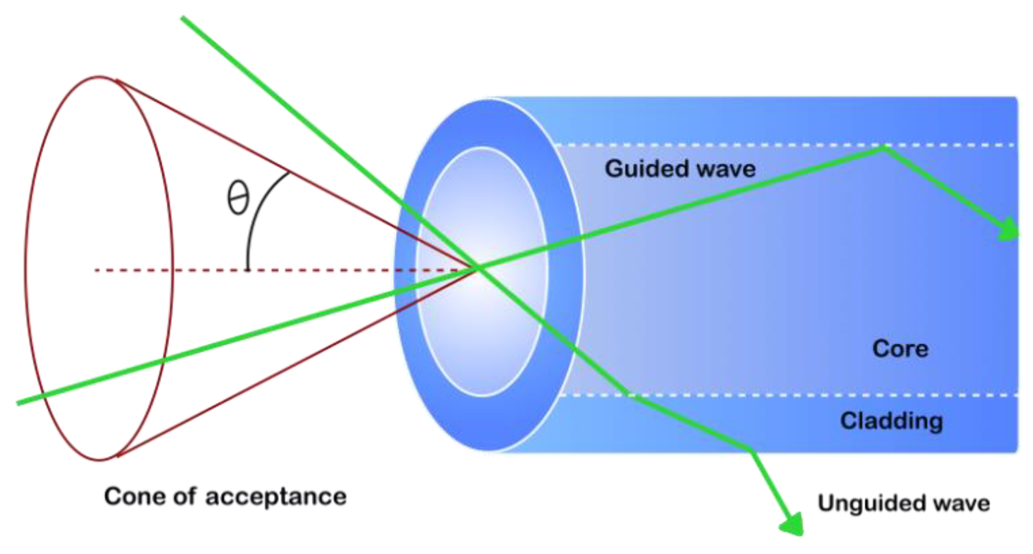
Figure 3.
(a) Schematic representation of evanescent waves for U-shape fiber sensor, (b) energy of evanescent field E as a function of the distance from the surface of the core dp.
Figure 3.
(a) Schematic representation of evanescent waves for U-shape fiber sensor, (b) energy of evanescent field E as a function of the distance from the surface of the core dp.
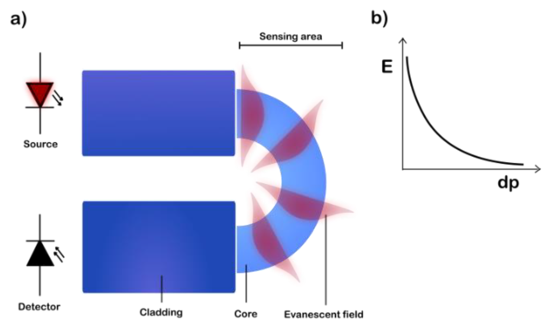
Figure 4.
a) Attenuation spectrums of sample 7 PMMA POF (-) before and (…) after surface fluorinating (reproduced with permission from Ref. [2],Wiley Copyright 2023), b) transmission loss fiber made by PC material (adapted with permission from [15], © The Optical Society), c) transmission loss for SI-POF fiber made with Zeonex and Topas materials (reproduced with permission Ref. [80], Elsevier Copyright 2023), d) attenuation of silica and polymer: PMMA and CYTOP fibers (based on ref [41]).
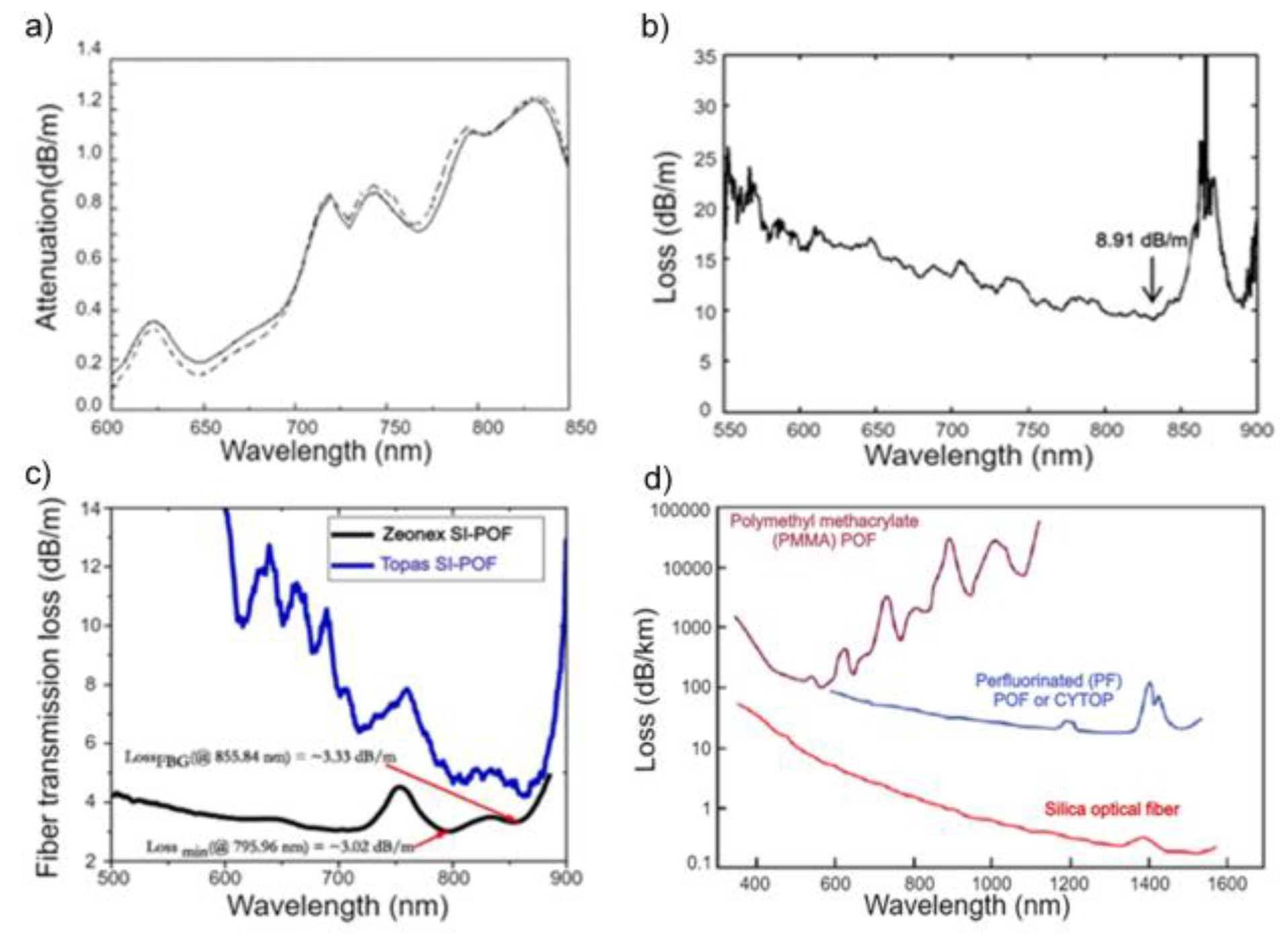
Figure 5.
Spider plot showing the material properties of POFs presented in Table 1. The values are ranked from 1 to 5, where a lower property value corresponds to a lower rank.
Figure 5.
Spider plot showing the material properties of POFs presented in Table 1. The values are ranked from 1 to 5, where a lower property value corresponds to a lower rank.
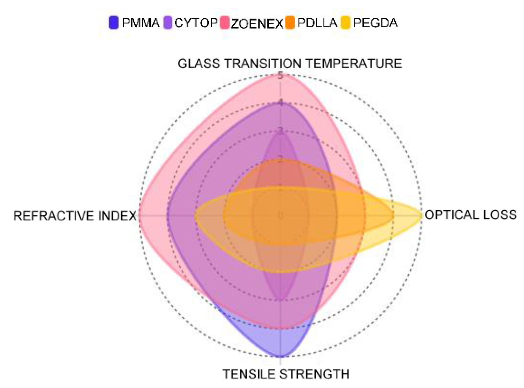

Table 1.
Comparison of material for POF u-shape sensor.
| Material | Refractive index of core | Optical loss [dB/m] | Tensile strength [MPa] |
Glass trans. temp. [ °C] |
Ref. |
|---|---|---|---|---|---|
| PMMA | 1.49 @850nm | 0.2 @650nm | 76 | 105-120 | [43,44,46] |
| CYTOP | 1.34 @589nm | 0.06 @850nm | 41-49 | 108 | [69,70] |
| ZOENEX | 1.52 @589nm | 2.34 @690nm | 63-70 | 139 | [50,75,76,77,78] |
| PDLLA | 1.45 @656nm | 11 @772nm | n.r.* | 58 | [11,90] |
| PEGDA | 1.46 @532nm | 40 @532nm | 2.8-9.5 | 26.3-51 | [88,89,91] |
*n.r. – non recorded.
Disclaimer/Publisher’s Note: The statements, opinions and data contained in all publications are solely those of the individual author(s) and contributor(s) and not of MDPI and/or the editor(s). MDPI and/or the editor(s) disclaim responsibility for any injury to people or property resulting from any ideas, methods, instructions or products referred to in the content. |
© 2024 by the authors. Licensee MDPI, Basel, Switzerland. This article is an open access article distributed under the terms and conditions of the Creative Commons Attribution (CC BY) license (http://creativecommons.org/licenses/by/4.0/).
Copyright: This open access article is published under a Creative Commons CC BY 4.0 license, which permit the free download, distribution, and reuse, provided that the author and preprint are cited in any reuse.


