Submitted:
04 December 2024
Posted:
05 December 2024
You are already at the latest version
Abstract
In this study, a (TiB + TiC + Y2O3)/α-Ti composites was prepared by induction skull melting to investigate its creep behavior and microstructure evolution under different temperatures and stresses. The results show that the microstructure of the composites in the as-cast state is a basket-weave structure, with the main phase composition is α lamella, containing a small amount of β phase and equiaxed α phase. The creep life of the composites decreases significantly when the temperature is increased from 650 °C to 700 °C, and the steady-state creep rate is increased by 1-2 orders of magnitude. The creep stress exponent at 650 °C and 700 °C is 2.92 and 2.96, respectively, and the creep mechanism of the titanium matrix composites are dominated by dislocation movement. TiB and TiC exhibit synergistic strengthening effects, and Y2O3 remains stable during creep. The reinforcements strengthen the composites by impeding the dislocation movement. The accelerated dissolution of β phase is one of the major reasons for the decrease of creep properties of composites with increasing temperature and stress. Silicide precipitation was observed near the reinforcements and dissolved β-Ti, mainly in elliptical or short rod shapes, which pins dislocations and improves the creep performance of the composites.
Keywords:
hybrid reinforcement
; creep behavior
; reinforcements
; silicide
1. Introduction
Titanium matrix composites (TMCs) combine the merits of titanium alloys and ceramic compounds, exhibiting exceptional properties such as low density, high specific strength, high temperature resistance, and corrosion resistance. Consequently, they are widely used as structural materials, especially in aerospace, military and other fields with significant application prospects [1,2,3]. The properties of TMCs are determined by the matrix, reinforcements and the bonding strength between them. At present, the most widely used matrix is near-α titanium alloy, which demonstrates superior temperature mechanical properties, plasticity and creep properties compared with other titanium alloys [4,5]. The near-α alloy is dominated by Ti-Al-Sn-Zr-Mo-Si alloy [6]. The reinforcements of TMCs mainly include ceramic phases and rare earth oxide phases with high melting points. TiB and TiC in ceramic phases with outstanding advantages and exhibit great bonding with matrix, so they are wide application at present. Research by Kurita [7] shows that the discontinuous distribution of TiB whisker in Ti-6Al-4V can significantly improve the yield strength of the material. In addition, compared with large-size whisker, the miniaturization of whisker can improve the plasticity of the material, while TiC can significantly improve the high-temperature bearing capacity of TMCs [8]. Among rare earth oxides, Y2O3 has the lowest density and low thermal expansion coefficient, which can significantly improve the creep resistance of the material. Yue added nano-sized Y2O3 to T4822 and found that there were a large number of twins and dislocations around Y2O3, resulting in a 26% increase in the material's strength [9]. Li [10] reported that the tensile yield strength of titanium matrix composites reinforced with 2.0 wt% Y2O3 particles can reach 1300 MPa at room temperature. A study have pointed out [11] that there is a synergistic effect between different reinforcements, and the effect of adding multiply reinforcements exhibiting a more significant impact than that of adding of a single phase. There is a synergistic effect observed between TiC and TiB, and the best synergistic effect is achieved when the volume ratio between the two reinforcements is 1:1, resulting in the best strengthening effect on the material [12,13]. Han [14] showed that the bonding between Y2O3 and the matrix after creep is better than TiB and TiC, so adding Y2O3 to the titanium matrix composites can further improve the stability of its high temperature performance.
Creep property is an important index to measure the properties of materials, which has important guiding significance for the application of materials. Material composition, temperature and stress all affect the creep behavior of materials. Silicon element has the effect of improving the creep performance of materials and will from solid solution to silicide during the creep process [15]. Silicides have a pinning effect on dislocations, which greatly improves the creep properties of materials whose creep mechanism is dislocation movement [16]. At present, some researchers have studied the precipitation of silicides and their effects in the creep process of multi-component hybrid reinforced TMCs [17,18], but the effects of different temperatures and stresses on creep behavior and silicide precipitation remain unclear.
Based on the above discussion, further research is needed to investigate the effects of temperature and stress on the creep behavior of TMCs and the microstructure evolution during the creep process. In this article, a titanium matrix composites hybrid reinforced with (TiB + TiC + Y2O3) was prepared by induction skull melting. The high temperature tensile creep experiments were conducted at different temperatures and stresses to analyze the effects of temperature and stress on creep behavior and microstructure evolution during creep.
2. Materials and Methods
2.1. Materials preparation
In this study, near-α alloy Ti-6Al-4Sn-8Zr-0.8Mo-1W-1Nb-0.25Si was selected as the matrix, 3 vol% (TiB + TiC) and 0.3 vol% Y2O3 were selected as reinforcements to prepared a (TiB + TiC + Y2O3)/α-Ti composites (Abbreviated as TMC) by induction skull melting with water-cooled copper crucible, where the volume ratio of TiB and TiC is 1:1. The raw materials for the preparation of TMC are high-purity Ti, Al, Sn, Zr and Si (Purity > 99%), and elements such as W, Mo and Nb are added by the way of intermediate alloys, including Al-Mo alloy (50.5 wt% Mo), Al-W alloy (57.44 wt% W) and Al-Nb alloy (83.15 wt% Nb), which facilitate accurate batching and simultaneously reduce melting temperature. TiB and TiC are obtained by adding B4C powder and C powder to the raw material, and in situ reaction with Ti during melting (5Ti + B4C =4TiB + TiC and Ti + C =TiC). Conversely, Y2O3 was obtained by directly adding nano-sized Y2O3 powder to the raw material.
The melting process must be completed under the protection of argon to avoid liquid metal splashing or reacting with active gases, which may lead to produce impurities. The powder raw materials are wrapped in aluminum foil, where C powder and other materials are put into the furnace for melting. Specifically, B4C and Y2O3 powder are first placed in the charging hopper and added to the furnace after the other raw materials are completely melted. After the melting is completed, it is necessary to continue stirring for a period of time before pouring to ensure the uniformity of the molten metal, and finally the molten metal completed by melting is poured into a metal mold to obtain a cast ingot with a diameter of 50 mm and a height of 70 mm.
2.2. Experimental procedure
Firstly, used X-ray diffraction (XRD, X'PERT) and scanning electron microscopy (SEM, Quanta 200FEG) characterized the TMC in the as-cast state. And the microstructure and phases composition were observed and analyzed to ensure that the desired enhanced phases were obtained in the melting process. The specimens required for the experiment were cut from the ingot by electric discharge wire cutting. The size of the samples to observe microstructure were 10 mm × 10 mm × 5 mm, and the dimension of gauge segment of the specimens for the high temperature tensile creep experiment were 10 mm×5 mm×2 mm. The specific shape and dimension of the specimens are shown in Figure 1. The high temperature tensile creep tests were conducted on the RDL100 tensile creep test machine at 650 °C and 700 °C, respectively, under experimental stresses ranging from 150 MPa to 200 MPa. Before the experiment, the surface of the specimens were polished with sandpaper to avoid the wire-cut defects affecting the experimental results. Attach a thermocouple to each of the upper, middle and lower parts of the specimen gauge segment to ensure the accuracy and stability of the temperature during the experiment. After the experiment, the fracture morphology of the fracture samples was observed and analyzed by SEM to study the creep fracture mode. For microstructural observation, cut off the deformed area of the sample and grind it to 3000 mesh sandpaper, then electrolytically polished, and then corroded with Kroll (3 vol% HF, 5 vol% HNO3, and 92 vol% H2O) solution, the deformed microstructure of the specimens were characterized by SEM. Select several representative specimens based on the scanning results, cut thin 300 μm slices using wire cutting, polished it to 50-60 μm by sandpaper, and then punch small circles with a diameter of 3 mm. Finally, use electrolytic double spraying to obtain thin areas for transmission electron microscopy (TEM, Talos F200X) characterization to further study the microstructure evolution of the composites. Comparing the microstructure of the samples after creep under different temperatures and stresses, to study the evolution of microstructure during creep and the impact of temperature and stress on the high temperature tensile creep behavior of TMCs.
3. Results and Discussion
3.1. Constituent phase identification and original microstructure
To ensure that the added B4C powder and C powder can completely react with Ti to form TiB and TiC, without the generation of other side reaction products, the TMC in the as-cast state was characterized by XRD, and the XRD pattern is shown in Figure 2a. The main phase composition of the TMC is α-Ti, with a relatively low of β-Ti. The diffraction peaks of TiB and TiC were found in the spectrum, while no diffraction peaks of raw materials or other products were observed, indicating that the reaction is complete and consistent with the expected results. Due to the addition of Y2O3 is too small, there is no diffraction peak in the spectrum.
The microstructure of TMC was further observed by SEM, and the SEM image was shown in Figure 2b. Obviously, it can be seen that the microstructure of the material in the as-cast state is a typical basket-weave structure. The reinforcements weaken the presence of grain boundary α phase and promotes the formation of basket-weave structure [17]. The main phases consist of TMC was α phase (grayish white) and β phase (black), and α phase is predominantly being lamellar, containing a small amount of equiaxed α phase. It can be seen that several reinforcements are evenly distributed in the matrix, and TiB grows fastest along the direction [010] [19], making it is easy to form whisker shape with relatively large aspect ratio. TiC is mainly equiaxed and distributed around TiB. Y2O3 is mainly micron-scale white granular or short rod-like, and the interface between Y2O3 and the matrix is very clean, without any reactant formation, which is the same as the situation in reference[20].
3.2. High temperature tensile creep properties
Figure 3 shows the creep curves and creep rate-strain curves of TMC under different temperatures and stresses, in which the experiments are interrupted at 150 h under 650 °C/150 MPa and 650 °C/175 MPa, while the experiments were stopped when the specimens fracture under other conditions. Figure 3a,b show the creep curves under different conditions. It can be observed from the creep curves that the creep of TMC has no obvious primary stage and quickly enters the steady state creep stage, and several specimens at 700 °C also enter the accelerating creep stage. The creep rate in the steady state creep stage can optimally represent the creep properties of material. According to the derivation of the creep curves, the creep rate was calculated and the creep rate-strain curves were made (Figure 3c,d), and then list the creep properties of TMC under different conditions in Table 1. The experimental results indicate that when the temperature increases by 50 °C, the steady creep rate increases by 1 to 2 orders of magnitude, and the creep life decreases by 80%. With the increase of stress, the creep rate changes relatively little, indicating that the temperature exerts a considerable influence on the creep rate.
The steady-state creep rate can be expressed by the power law relationship [21]:
In this equation, represents creep rate, A is a material dependent constant, σ represents creep stress (MPa), n is the creep stress exponent, Q is the creep activation energy (kJ/mol), R is a constant, and T is the Kelvin temperature (K).
According to the data in Table 1 and Equation 1, a double logarithmic plot illustrating relationship between the creep rate and stress of TMC at 650 °C and 700 °C was made (Figure 4). The creep stress exponent of TMC at 650 °C and 700 °C were 2.92 and 2.96 respectively, both of which are close to 3, indicating that the creep mechanism of TMC is dislocations movement [22].
3.3. Creep deformed microstructure and fracture morphology
Figure 5 shows the SEM characterization result of the deformation region of the specimens after creep under different conditions. As shown in Figure 5a,b, at 650 °C/150 MPa, TiB remain intact, while debonding occurs between TiC and matrix. TiC precipitated separately is branched structure, while TiB can be used as a heterogeneous nucleating particle of TiC. During solidification, TiC and TiB will form a symbiotic microstructure as shown in Figure 5a,b. This microstructure effectively reducing the quantity of TiC branched crystals, resulting in TiC appearing as oval granular morphology and distributed near TiB [23,24]. The strengthening mechanism of discontinuous reinforcements is load transfer strengthening [25], and the TiB with a larger aspect ratio plays a more significant role in transfer strengthening [26]. Therefore, due to stress concentration TiB breaks first during the creep process. The interface between Y2O3 and the matrix is still intact after creep, and no debonding phenomenon occurs.
Figure 6 shows the deformed microstructure after creep under different stresses at 700 °C. With the increase of temperature, the matrix softens, the load transfer makes the stress on the TiB more concentrated, result in more severe fracture, and the cracks and voids in the deformed structure increase significantly. Moreover, the debonding between matrix and TiB or TiC become more serious, indicating that the bonding strength between the two reinforcements and the matrix decreases further with the increase of temperature. According to Figure 5 and Figure 6, with the increase of stress, the fracture of the reinforcements and the debonding between the reinforcements and the matrix become more severe. The number and dimension of cracks and voids along the reinforcements increase, and the cracks and voids gradually expand and connect during the creep process, ultimately causing specimens failure.
Figure 7 shows the fracture morphologies of specimens after creep under different conditions. The specimens at 650 °C/150 MPa and 650 °C/175 MPa did not fracture. Comparing the conditions of Figure 7a 650 °C/200 MPa and Figure 7d 700 °C/200 MPa, it was observed that there a large number of tearing edges exist in the fracture surface at the lower temperature, indicative the fracture mode is brittle fracture. As the temperature increases, tearing edges decreases, while dimples increase significantly, and the fracture mode changes to mixed fracture. There are voids in Figure 7b-d, which is due to the stress concentration near the reinforcements during creep, and the bonding strength between the reinforcements and the matrix at high temperature is weaker than the strength of the reinforcements themselves. As a result, debonding occurs between reinforcements and matrix under the action of stress and micropores. Compared with the fracture morphology under different stresses at 700 °C, it was observed that the fracture morphology has no obvious change with the increase of stress, indicating that the stress has little effect on the fracture mode.
3.4. Microstructure evolution during creep
As previously mentioned, the precipitation of silicide occurs during the creep process, other factors such as temperature [15] and element composition [27] will affect the silicide precipitation. Figure 8 shows the TEM images of TMC specimens after creep at 650 °C/150 MPa. Figure 8a shows the morphology and distribution of the silicide precipitated, and Figure 8b-e shows the energy spectrum analysis of the corresponding region. It can be seen from the figures that the silicides precipitated under this condition are ternary compounds composed of Ti, Zr and Si.
Figure 9a shows that the silicides are mainly exhibit a short rod-like morphology and distributed around the α/β colonies. As show in Figure 9b that silicide have a pinning effect on the dislocations, which effectively inhibits further expansion of the dislocation and thus improves the creep resistance of TMC [17,28]. Figure 9c,d show the dissolution of β-Ti during the creep process and the dislocations distribution around it. Due to the different solubility of silicon in the two phases, the dissolution of β-Ti promotes the precipitation of silicides, which is also the reason why silicides are mainly distributed around the α/β colonies. It is well known that the phase boundary has a hindering effect on dislocation motion, so the complete α/β colonies plays a significant limiting role in the movement of the dislocations. During the creep process, the gradually dissolves of β-Ti leads to the α/β colonies is destroyed, and the limiting effect on dislocation movement is weakened, so the matrix will gradually soften and accelerate the fracture of the specimen.
Figure 10 shows TEM images of the deformed microstructure of TMC after creep at 700 °C/150 MPa. Figure 10a shows the dissolution of β-Ti and the precipitation of silicides in its vicinity during creep. It is observed that the dissolution of β-Ti is exacerbated with the increase of temperature, and the restraining effect of α/β colonies on dislocation movement is weakened, lead to the creep performance of the material deteriorates accordingly. Consequently, the dissolution of β-Ti is one of the main reasons for the decrease of the creep properties of materials with increasing temperature. The dissolution of β-Ti resulted in a corresponding increase in the precipitation of silicides in the adjacent areas. Figure 10b shows that under the influence of silicides, the dislocations were basically parallel, and the silicides had a pinning effect on the dislocations, causing them to stopped expanding when they moved to the region near the silicides.
3.5. The influence of reinforcements on microstructure and creep properties
The influence of reinforcements on the creep properties of materials can be attributed to two aspects. On the one hand, the influence of the reinforcements on the microstructure of composites changes its creep properties. As mentioned earlier, the creep mechanism of the material in this study is dislocation movement, so the microstructure of the material has a very important influence on its creep properties. The addition of reinforcements such as TiB and TiC can change the microstructure of the material from the Widmanstatten microstructure to the basket-weave structure (see Figure 2b). Compared to the Widmanstatten microstructure, the basket-weave structure has better creep resistance, fatigue properties, creep properties and plasticity [29,30]. Reinforcements such as TiB, TiC and Y2O3 have the effect of refining grains [31,32,33], and it is worth noting that Y2O3 can also reduce the spacing of α laminates [34]. The reduce of grain size leads to a decrease in the effective slip length of dislocations, and the creep resistance increases, thus improving the creep property of the material. In addition, these reinforcements facilitate the homogeneity of the material microstructure and improve its overall properties [35]. On the other hand, the reinforcements themselves play a role in improving the creep performance of the material. As shown in Figure 11e,f, during the creep process, the reinforcements can hinder the migration of dislocations and increase the dislocation density in their vicinity, thus improving the creep performance of the material. TiB plays a role in bearing loads and increases the creep resistance of materials.
Figure 11 shows the morphology of the reinforcements of TMC after creep at 650 °C/150 MPa and 700 °C/150 MPa, and the silicides and sub-grains near the reinforcements. Figure 11a and Figure 11b shows the morphology of TiB and its adjacent sub-grains after creep at 650 °C/150 MPa. The TiB can effectively hinder the migration of dislocations, causing the dislocations accumulate near it. Due to the spontaneous reduction of energy, the high density of the dislocations will be rearranged and form sub-grains. Under this condition, dislocations still exist at the edge of the sub-grain, indicating that it is still in an unstable state [36]. Figure 11c shows that there are large amounts of silicides around TiB, and TiB whisker accelerates the silicide precipitation behavior by hindering the migration of dislocations and providing nucleation sites for silicides[37]. Figure 11d shows the microstructure morphology of sub-grains after creep at 700 °C/150 MPa, where no dislocations exists at the edge, and it is already in a stable state, indicating that temperature increase accelerates the migration of dislocations and promotes dynamic recrystallization.
Reinforcements also has an adverse effects on the overall properties of composites. During the process of tensile fracture, cracks are easy to occur near the reinforcements, so the addition of the reinforcements leads to a decrease in the plasticity of the material [38]. In addition, as shown in Figure 11 that the α phase around TiB are all equiaxial. Mohan [39] have shown that TiB can act as the heterogeneous nucleation sites of fine β-Ti in liquid titanium and eventually transform into equiaxed α grains. Feng [40] also found that α-Ti near TiB is prone to spheroidization behavior. The α/β colonies is semi-coherent [41], which helps to hinder the migration of the dislocations, while the equiaxial α and β interface is incoherent, and the dislocations moves faster. Consequently, equiaxial α-Ti has a negative effect on the creep properties of the composites. In this study, the amount of TiB added was small, so the content of equiaxial α is small (As show in Figure 3), and the influence on the creep properties of the composites is negligible.
3.6. Precipitation of silicides
The silicon element in the composites will gradually precipitate to form silicide during creep process. The previous text pointed out that silicides are prone to precipitate near the dissolved β phase or the reinforcements. The density of dislocations near the reinforcements is elevated, and the dislocations can accelerate the diffusion rate of elements, thus promoting the precipitation of silicides [42].
Figure shows the silicides near TiB after creep at 650 °C, there are both ellipsoidal or rod-like S2 silicides (Figure 8, Figure 9, and Figure 10) and large size equiaxed silicides (Figure 12) were observed. The presence of Zr element can promote the precipitation of silicide, as Zr is a β-stable element. Moreover, the affinity between Si and Ti is lower than that between Si and Zr [27]. Therefore, some Ti elements are replaced by Zr during the formation of silicides, and the silicides precipitated at 650 °C/150 MPa are Ti, Zr, Si ternary silicides. In addition, Zr has the effect of refining silicides [43].
With the increase of stress, the diffusion rate of atoms is significantly accelerated, which is conducive to the growth of silicides, so the size of silicides formed after creep at 650 °C/200 MPa is significantly larger than that after creep at 650 °C/150 MPa(Figure 12). According to the energy spectrum analysis in Figure 12, a portion of Si of the silicide precipitated at 650 °C/200 MPa is replaced by Sn to form quaternary silicide. The high-resolution image and diffraction spots of the silicide are shown in Figure 12g. The silicide has a close-packed hexagonal structure, and the direction (20) of the silicide is parallel to the direction (010) of the TiB. With the increase of temperature, the dissolution degree of β phase increases at 700 °C, and the silicide precipitated near it increases correspondingly. At present, the mechanism of the influence of temperature on the precipitation of silicides is still unclear. Kartamyshev [44] pointed out that S1 silicides are more easily formed at high temperature, while S2 silicides are more easily formed at low temperature.
3.7. Effect of silicides on creep behavior
Silicon element has a significant effect on the creep behavior of TMCs. The solubility of Si element in α phase and β phase is different. During the creep process, due to temperature change and element diffusion, silicon element will further segregate to form silicides. Silicides limit grain boundary slip in the primary creep stage, while limit dislocation slip in the steady state creep stage and accelerated creep stage [45]. The main creep mechanism of composites in this study is dislocation slip, so the strengthening mechanism of silicide creep behavior is its hindrance to dislocation movement. On the one hand, the pinning effect of fine silicides on dislocation is stronger than that coarse silicides, and increase temperature and stress will coarsening silicide, resulting in the weakening of its strengthening effect on composites [17]. On the other hand, with the increase of temperature, silicon elements are more likely to form S1 silicides, and the short-rod-shaped S1 silicides have better dislocation pinning effect than the spherical S2 silicides [46]. In addition, the size of silicides is also related to the reinforcements. As shown in Figure 12f, due to the stacking fault structure of TiB whisker, the size of silicides formed near it is significantly larger than that around TiC and Y2O3 [47].
However, the strengthening effect of silicide on composites is limited. If the added Si is too little, the silicide will not be precipitated during the creep process, if the added Si is too much, the size of the silicide precipitated will increase and the non-uniformity will increase, thus weakening the strengthening effect. Even if an appropriate amount of Si element is added, as shown in Figure 8-12, due to the difference in the solubility of Si in the α and β, the distribution of silicides in the material is uneven, so only a small part of the dislocations can be pinned, and the strengthening of the creep properties of the composites is very limited.
4. Conclusion
In this study, a (TiB + TiC + Y2O3)/α-Ti composites was prepared by induction skull melting. and then conducts high temperature tensile creep experiments under different conditions. Detailed analysis the effects of reinforcements and silicide on creep behavior, and the main conclusions were summarized as follows:
- The as-cast microstructure of the composites is basket-weave structure, the main phase composition is lamellar α phase and a relatively low content of β phase, TiB is a whisker with large aspect ratio, TiC is equiaxed and mostly distributed near TiB, Y2O3 is micron-meter granular.
- When the temperature increases from 650 °C to 700 °C, the steady-state creep rate of the composites increases by 1-2 orders of magnitude, and the creep life decreases significantly. After creep, TiB fractures and there is debonding between TiC and the matrix, while Y2O3 remains intact and has good bonding with the matrix.
- The creep stress exponent of the composites at 650 °C and 700 °C is 2.92 and 2.96 respectively, indicating the main creep mechanism of this composites is dislocation slip. Temperature and stress have no significant effect on the creep mechanism of the composites.
- The α/β interface has a hindering effect on the dislocation movement. With the increase of temperature or stress, the dissolution degree of the β phase increases, the α/β colonies is destroyed, and the limiting effect on the dislocation movement is weakened. Therefore, the increase of the dissolution degree of the β phase is one of the main reasons for the decrease of the creep life of the composites.
- The reinforcements can improve composites structure, withstand loads and hinder the dislocation movement during the creep process. Silicides precipitated near TiB and the α/β interface during creep can also restrict dislocation movement, thus reducing the creep rate and extending the creep life.
Author Contributions
Conceptualization, X.W., Y.Z. and S.X.; methodology, X.W., Y.Z. and L.X.; formal analysis, X.W. and Y.Z.; investigation, Y.Z., S.H., S.X. and J.T.; resources, J.T. and L.X.; data curation, X.W.; writing-original draft preparation, X.W.; writing-review and editing, X.W., S.H., S.X. and L.X.; project administration, L.X.; funding acquisition, L.X. All authors have read and agreed to the published version of the manuscript.
Funding
This research did not receive any grant.
Institutional Review Board Statement
Not applicable.
Informed Consent Statement
Not applicable.
Data Availability Statement
The original contributions presented in the study are included in the article, further inquiries can be directed to the corresponding author.
Acknowledgments
The authors are grateful to the School of Materials Science and Engineering of Harbin Institute of Technology for supporting and providing the facilities for this research.
Conflicts of Interest
The authors declare no conflicts of interest.
References
- Jiao, Y.; Huang, L.; Geng, L. Progress on discontinuously reinforced titanium matrix composites. J. Alloys. Compd. 2018, 767, 1196–1215. [Google Scholar] [CrossRef]
- Le, J.; Han, Y.; Qiu, P.; Huang, G.; Mao, j.; Lu, W. The Impact of matrix texture and whisker orientation on property anisotropy in titanium matrix composites: Experimental and computational evaluation. Compos. Part. B-eng 2021, 212, 108682. [Google Scholar] [CrossRef]
- Yuan, Z.; Liu, H.; Ma, Z.; Ma, X.; Wang, K.; Zhang, X. Microstructure and properties of high entropy alloy reinforced titanium matrix composites. Mater. Charact. 2022, 187, 111856. [Google Scholar] [CrossRef]
- Han, Y.; Zeng, W.; Qi, Y.; Zhao, Y. The influence of thermomechanical processing on microstructural evolution of Ti600 titanium alloy. Mater. Sci. Eng. A 2011, 528, 8410–8416. [Google Scholar] [CrossRef]
- Gao, X.; Zeng, W.; Zheng, S.; Wang, Q. A study of epitaxial growth behaviors of equiaxed alpha phase at different cooling rates in near alpha titanium alloy. Acta Mater. 2017, 122, 298–309. [Google Scholar] [CrossRef]
- Zhang, T.; Yue, K.; Yu, J.; Huang, Z.; Teng, A. Research overview and application of high-temperature titanium alloy and titanium matrix (Ti-Al) composites for aerospace. The Chinese Society for Metals. Proceedings of the 14th China Iron and Steel Annual Conference, 6: steel materials and applications, 2023, 2023. [Google Scholar]
- Kurita, H.; Suzuki, S.; Kikuchi, S.; Yodoshi, N.; Gourdet, S.; Narita, F. Strengthening Mechanism of Titanium Boride Whisker-Reinforced Ti-6Al-4V Alloy Matrix Composites with the TiB Orientation Perpendicular to the Loading Direction. Materials 2019, 12, 2401. [Google Scholar] [CrossRef]
- Qi, J.; Chang, Y.; He, Y.; Sui, Y.; Wei, F.; Meng, Q.; Wei, Z. Effect of Zr, Mo and TiC on microstructure and high-temperature tensile strength of cast titanium matrix composites. Mater. Des. 2016, 99, 421–426. [Google Scholar] [CrossRef]
- Yue, H.; Peng, H.; Miao, K.; Gao, B.; Wu, H.; Yang, J.; Fan, G. Significant enhancement in high-temperature tensile strength of trace nano-Y2O3-reinforced TiAl alloy prepared by selective electron beam melting. Mater. Sci. Eng. A 2023, 875, 145086. [Google Scholar] [CrossRef]
- Li, A.; Ma, S.; Yang, Y.; Zhou, S.; Shi, L.; Liu, M. Microstructure and mechanical properties of Y2O3 reinforced Ti6Al4V composites fabricated by spark plasma sintering. J. Alloys. Compd 2018, 768, 49–56. [Google Scholar] [CrossRef]
- Zheng, Y.; Xu, L.; Chi, D.; Liang, Z.; Han, S.; Xue, X.; Xiao, S.; Tian, J.; Chen, Y. Tensile and creep properties under different temperature conditions of titanium matrix composites reinforced by TiB and TiC. Mater. Sci. Eng. A 2022, 860, 144279. [Google Scholar] [CrossRef]
- Wu, L.; Gao, Z.; Fan, Z.; Liu, C.; Liu, Y. Microstructure and mechanical properties of in-situ hybrid reinforced (TiB plus TiC)/Ti composites prepared by laser powder bed fusion. J. Mater. Res. Technol. 2024, 30, 9258–9237. [Google Scholar] [CrossRef]
- Li, S.; Kondoh, K.; Imai, H.; Chen, B.; Jia, L.; Umeda, J.; Fu, Y. Strengthening behavior of in situ-synthesized (TiC-TiB)/Ti composites by powder metallurgy and hot extrusion. Mater. Des. 2016, 95, 127–132. [Google Scholar] [CrossRef]
- Han, S.; Xu, L.; Zheng, Y.; Liang, Z.; Chi, D.; Tian, J.; Xiao, S. Short-time creep behavior of (TiB + TiC + Y2O3) reinforced titanium matrix composites in the range of 600 °C to 700 °C, Mater. Charact. 2024, 210, 113785. [Google Scholar] [CrossRef]
- Yang, Z.; Zhang, C.; Ji, X.; Zhang, S.; Feng, H.; Han, J.; Peng, P.; Wang, T. Microstructural evolution and silicide precipitation behavior of TiCp/near-α titanium matrix composites during hot compression. Mater. Charact. 2022, 189, 1119333. [Google Scholar] [CrossRef]
- Paton, N.; Mahoney, M. Creep of titanium-silicon alloys. Metall. Trans. A. 1976, 7, 1685–1694. [Google Scholar] [CrossRef]
- Zheng, Y.; Xu, L.; Yu, J.; Liang, Z.; Xue, X.; Xiao, S.; Tian, J.; Chen, Y. Effect of TiB, TiC and Y2O3 on tensile properties and creep behavior at 650 °C of titanium matrix composites. J. Alloys. Compd 2022, 908, 164699. [Google Scholar] [CrossRef]
- Zheng, Y.; Xu, L.; Chen, Z.; Wang, X.; Xue, X.; Xiao, S.; Tian, J.; Chen, Y. Effects of hybrid reinforcements to the high temperature tensile and creep properties of a (TiB + TiC + Y2O3)/α-Ti composites. Mater. Charact. 2022, 190, 112067. [Google Scholar] [CrossRef]
- Huang, L.; Wang, L.; Qian, M.; Zou, J. High tensile-strength and ductile titanium matrix composites strengthened by TiB nanowires, Scr. Mater. 2017, 141, 133–137. [Google Scholar]
- Lu, W.; Mao, L.; Xu, D.; Qin, J.; Zhang, D. Microstructural characterization of Y2O3 in in situ synthesized titanium matrix composites. J. Alloys. Compd. 2007, 433, 140–146. [Google Scholar] [CrossRef]
- Gu, Y.; Zeng, F.; Qi, Y.; Xia, C.; Xiong, X. Tensile creep behavior of heat-treated TC11 titanium alloy at 450-550 °C. Mater. Sci. Eng. A 2013, 575, 74–85. [Google Scholar] [CrossRef]
- Abdallah, Z.; Gray, V.; Whittaker, M.; Perkins, K. A critical analysis of the conventionally employed creep lifing methods. Materials 2014, 5, 3371–3398. [Google Scholar] [CrossRef] [PubMed]
- Liu, S.; Shin, Y. The influences of melting degree of TiC reinforcements on microstructure and mechanical properties of laser direct deposited Ti6Al4VTiC composites, Mater. Des. 2017, 136, 185–195. [Google Scholar]
- Zhang, J.; Zhao, X.; Yang, M.; Yang, Z. Microstructural evolution and mechanical of titanium matrix composites with second-phase dendritic TiC improved through B4C additions. Ceram. Int. 2024, 50, 17482–17491. [Google Scholar] [CrossRef]
- Zhao, S.; Xu, Y.; Pan, C.; Liang, L.; Wang, X. Microstructural Modeling and Strengthening Mechanism of TiB/Ti-6Al-4V Discontinuously-Reinforced Titanium Matrix Composites. Materials 2019, 12, 827. [Google Scholar] [CrossRef]
- Bao, Y.; Huang, L.; An, Q.; Liu, Y.; Gong, D.; Cui, L.; Geng, L.; Hong, C. Wire-arc additive manufacturing of TiB/Ti6Al4V composites using Ti-TiB2 cored wire: processing, microstructure and mechanical properties. Virtual and Physical Prototyping 2024, 19, e2383287. [Google Scholar] [CrossRef]
- Zhao, E.; Sun, S.; Zhang, Yu. Recent advances in silicon containing high temperature titanium alloys. J. Mater. Res. Technol. 2021, 14, 3029–3042. [Google Scholar] [CrossRef]
- Liu, Z.; Zhu, P.; Mao, X.; Zhao, Y.; Xin, S. Effect of Si addition on the microstructure and creep properties of the forged titanium alloy. Mater. Chem. Phys, 2024, 317, 129212. [Google Scholar] [CrossRef]
- Qiu, J.; Ma, Y.; Lei, J.; Liu, Y.; Huang, A.; Rugg, D.; Yang, R. A Comparative study on dwell fatigue of Ti-6Al-2Sn-4Zr-xMo (x=2 to 6) alloys on a microstructure-normalized basis. Metal. Mater. Trans. A, 2014, 45, 6075–6087. [Google Scholar] [CrossRef]
- Wang, S.; Huang, L.; Jiang, S.; Zhang, R.; Liu, B.; Sun, F.; An, Q.; Jiao, Y.; Geng, L. Microstructure evolution and tensile properties of as-rolled TiB/TA15 composites with network microstructure. Mater. Sci. Eng. A 2021, 804, 140783. [Google Scholar] [CrossRef]
- Wang, H.; Hu, Z.; Cheng, X.; Zhang, Z.; Song, Q.; Li, X. A rapid route to fabricate in situ TiB-whisker-reinforced Ti-6Al-4V alloy composites by spark plasma sintering and heat treatment. Mater. Res. Express 2019, 6, 1265d3. [Google Scholar] [CrossRef]
- Zhang, C.; Kong, F.; Xiao, S.; Zhao, E.; Xu, L.; Chen, Y. Evolution of microstructure and tensile properties of in situ titanium matrix composites with volume fraction of (TiB + TiC) reinforcements. Mater. Sci. Eng. A 2012, 548, 152–160. [Google Scholar] [CrossRef]
- Castro, V.; Leguey, T.; Muñoz, A.; Monge, M.; Pareja, R. Microstructure and tensile properties of Y2O3-dispersed titanium produced by arc melting. Mater. Sci. Eng. A 2006, 422, 189–197. [Google Scholar] [CrossRef]
- Shen, J.; Fu, B.; Wang, Y.; Dong, T.; Li, J.; Li, G.; Liu, J. Effect of Y Content on Precipitation Behavior, Oxidation and Mechanical Properties of As-Cast High-Temperature Titanium Alloys. Materials 2023, 16, 4784. [Google Scholar] [CrossRef] [PubMed]
- Sun, S.; Wang, L.; Qin, J.; Chen, Y.; Lu, W.; Zhang, D. Microstructural characteristics and mechanical properties of in situ synthesized (TiB + TiC)/TC18 composites, Mater. Sci. Eng. A 2011, 530, 602–606. [Google Scholar] [CrossRef]
- Zheng, Y.; Xu, L.; Liang, Z.; Yu, J.; Wang, X.; Xiao, S.; Xue, X.; Tian, J.; Chen, Y. Investigation of three-step heat treatments on the microstructure and steady-state creep behaviors of (TiB + TiC + Y2O3)/α-Ti composites. Mater. Charact. 2023, 204, 113181. [Google Scholar] [CrossRef]
- Zhao, E.; Sun, S.; Yu, J.; An, Y.; Chen, W.; Chen, R. Dynamic recrystallization and silicide precipitation behavior of titanium matrix composites under different strains. T. Nonferr. Metal.Soc. 2021, 31, 3416–3427. [Google Scholar] [CrossRef]
- Xian, S.; Han, Y.; Huang, G.; Mao, J.; Wang, L.; Lu, W. In situ characterization of tensile fracture of TiB + La2O3 / Ti matrix composites and its mechanism. Hot Working Technology 2019, 48, 102–106. [Google Scholar]
- Nartu, M.; Mantri, S.; Pantawane, M.; Ho, Y.; McWilliams, B.; Cho, K.; Dahotre, N.; Banerjee, R. In situ reactions during direct laser deposition of Ti-B4C composites. Scr. Mater. 2020, 183, 28–32. [Google Scholar] [CrossRef]
- Feng, Y.; Zhang, W.; Zeng, L.; Cui, G.; Chen, W. Room-Temperature and High-Temperature Tensile Mechanical Properties of TA15 Titanium Alloy and TiB Whisker-Reinforced TA15 Matrix Composites Fabricated by Vacuum Hot-Pressing Sintering. Materials 2017, 10, 424. [Google Scholar] [CrossRef]
- Wang, K.; Li, M. Morphology and crystallographic orientation of the secondary α phase in a compressed α/β titanium alloy. Scr. Mater. 2013, 68, 964–967. [Google Scholar] [CrossRef]
- Sun, S.; Zhao, E.; Hua, C.; Ana, Y.; Chen, W. Precipitation behavior of silicide and synergetic strengthening mechanisms in TiB-reinforced high-temperature titanium matrix composites during multi-directional forging. J. Alloys Compd. 2021, 867, 159051. [Google Scholar] [CrossRef]
- Cao, S.; Li, Y.; Zhang, L.; Yang, Y.; Liu, J.; Yang, R.; Hu, Q. Alloying Effect on the Stability of Ti5Si3 from First-Principles Study. Phys. Status Solidi B 2022, 259, 2100434. [Google Scholar] [CrossRef]
- Kartamyshev, A.; Poletaev, D.; Lipnitskii, A. The influence of lattice vibrations and electronic free energy on phase stability of titanium silicides and Si solubility in hcp titanium: a DFT study. Calphad. 2019, 65, 194–203. [Google Scholar] [CrossRef]
- Liu, Z.; Xin, S.; Zhao, Y.; Dang, B. Effect of Silicide and α2 Phase on the Creep Behavior of TC25G Alloy at High Temperature. Met. Mater. Int. 2024, 30, 2158–2168. [Google Scholar] [CrossRef]
- Xu, L.; Zheng, Y.; Liang, Z.; Tian, Y.; Yang, J.; Wang, X.; Xiao, S.; Xue, X.; Tian, J. Impact of long-term thermal exposure on the microstructure and creep resistance of (TiB + TiC + Y2O3)/α-Ti composites. J. Alloys. Compd 2024, 990, 174496. [Google Scholar] [CrossRef]
- Xu, L.; Zheng, Y.; Liang, Z.; Han, S.; Xue, X.; Xiao, S.; Tian, J.; Chen, Y. Creep behavior and microstructure evolution of titanium matrix composites reinforced with TiB, TiC and Y2O3. T. Nonferr. Metal.Soc. 2023, 33, 467–480. [Google Scholar] [CrossRef]
Figure 1.
Dimensions of tensile creep specimens (in mm).
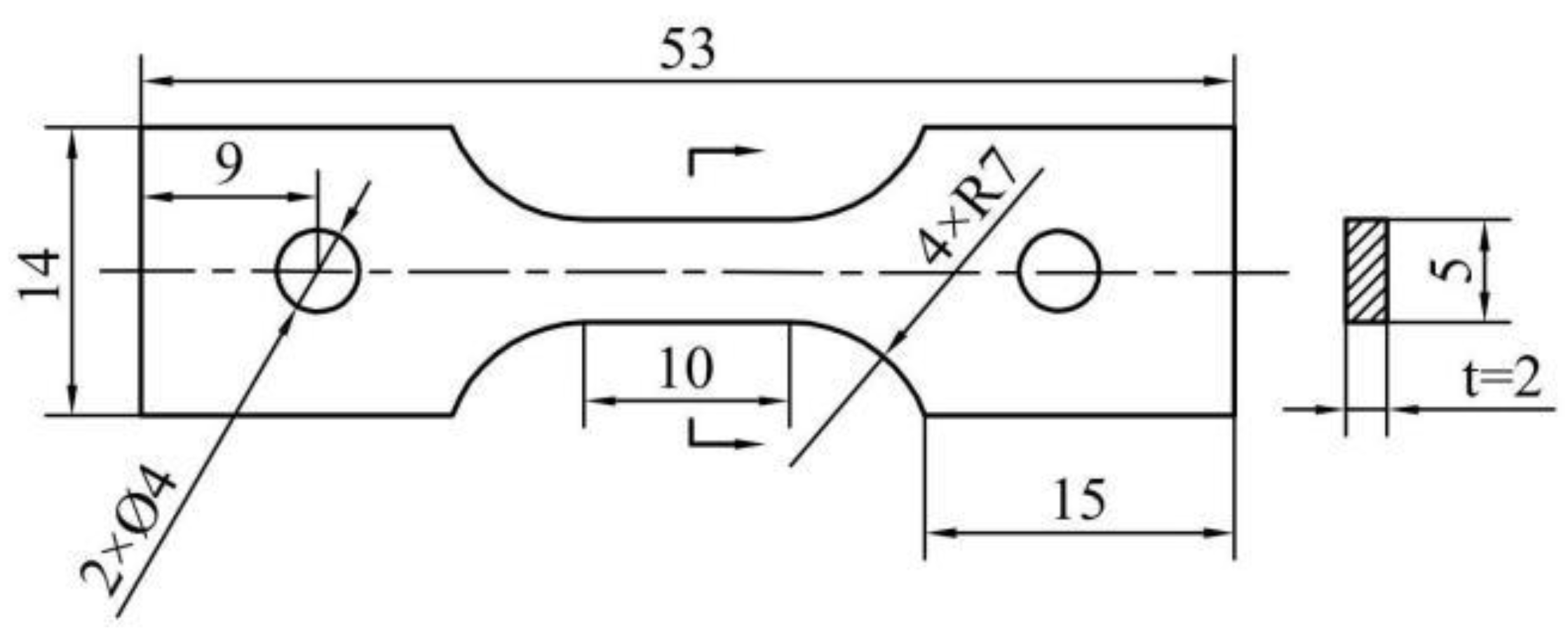
Figure 2.
XRD pattern and SEM image of TMC: (a) XRD pattern; (b) SEM image.
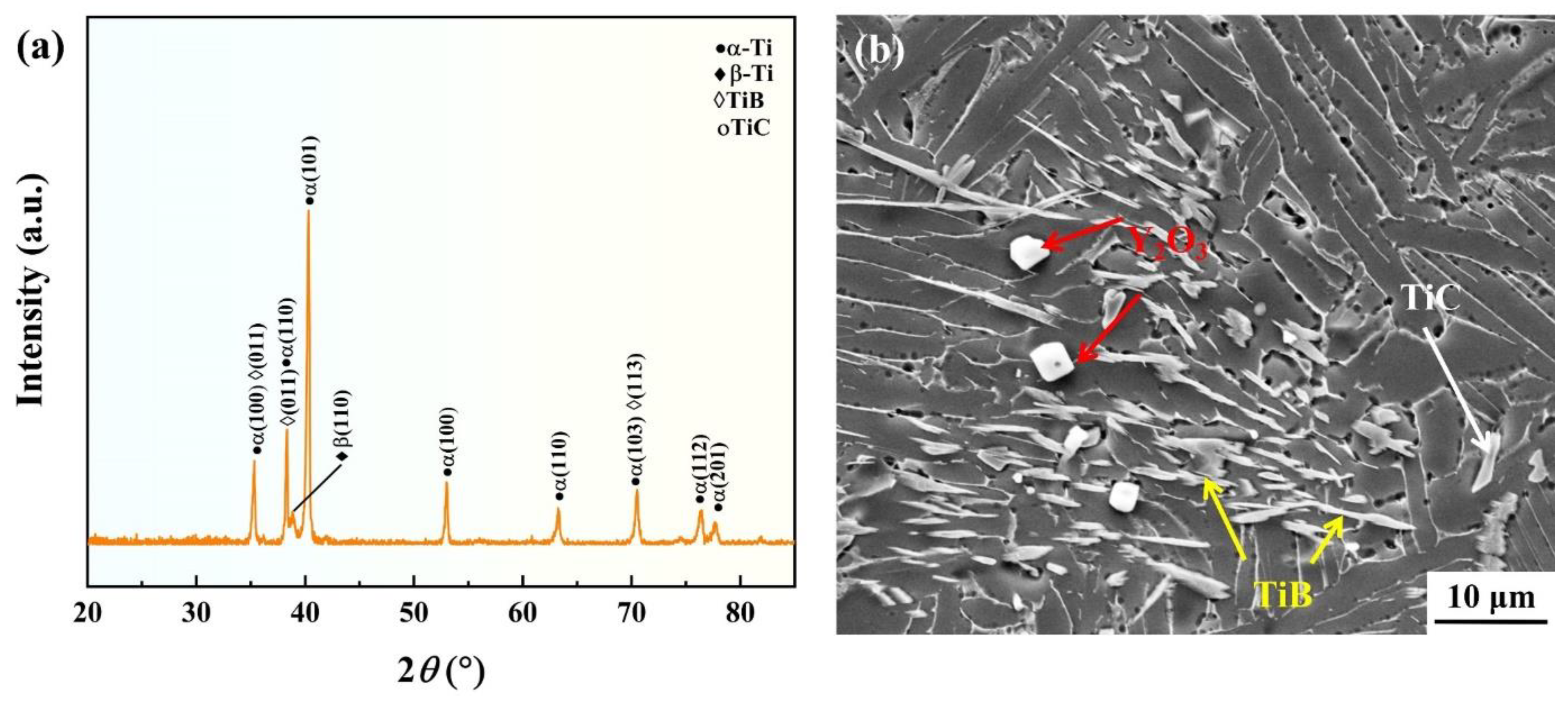
Figure 3.
Creep curves and creep rate-strain curves of TMC at different temperatures and stresses: (a) creep curves under different stresses at 650 °C; (b) creep curves at different stresses at 700 °C; (c) creep rate-strain curves under different stresses at 650 °C; (d) creep rate-strain curves at different stresses at 700 °C.
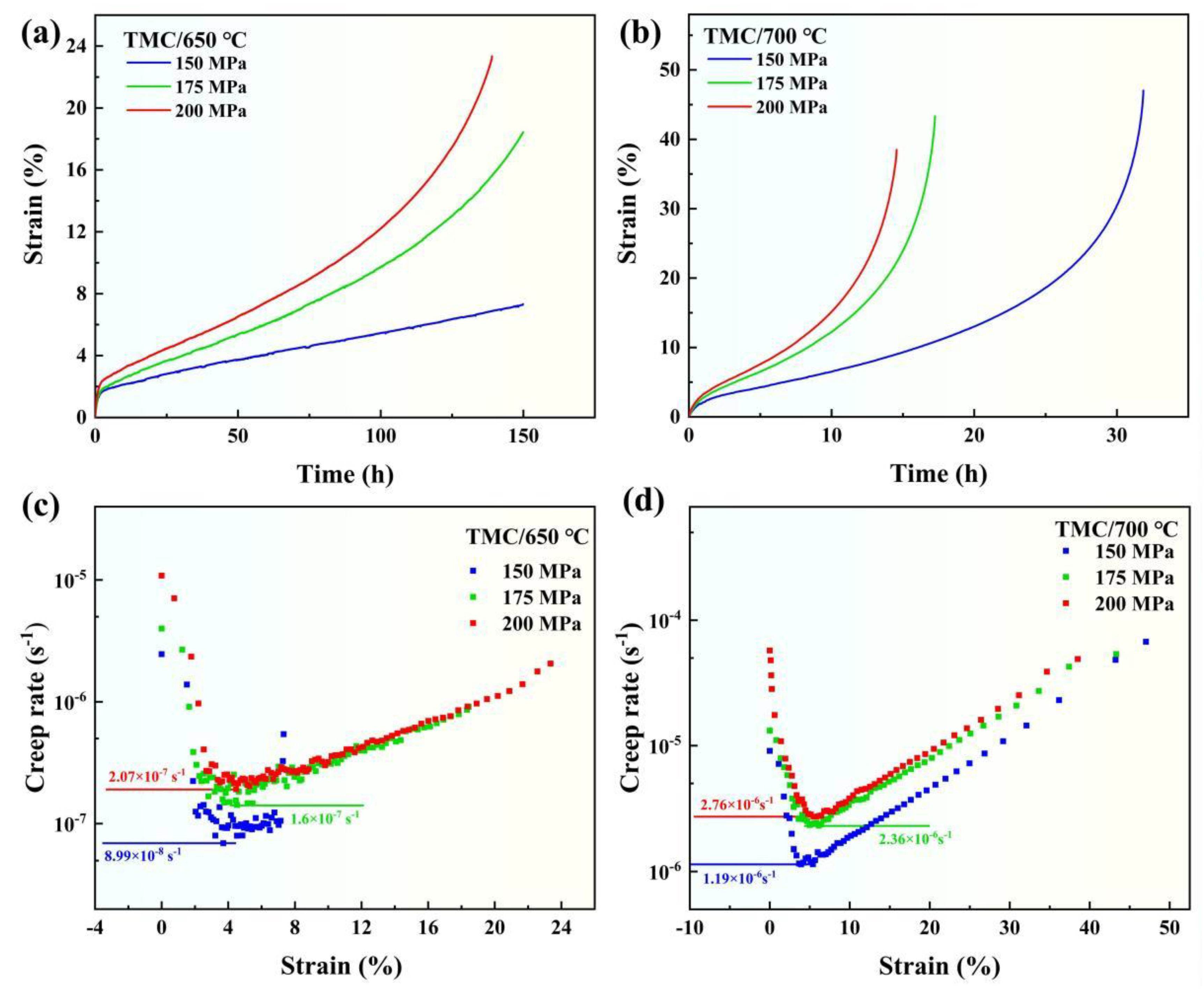
Figure 4.
Logarithmic relationship between creep rate and stresses of TMC at 650 °C and 700 °C.
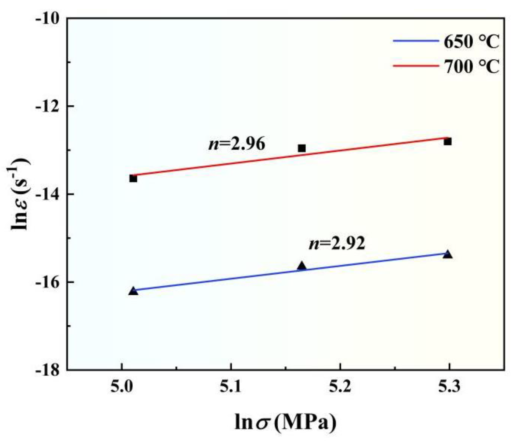
Figure 5.
Creep deformation of TMC at 650 °C under different stresses: (a,b) 150 MPa; (c,d) 175 MPa; (e,f) 200 MPa.
Figure 5.
Creep deformation of TMC at 650 °C under different stresses: (a,b) 150 MPa; (c,d) 175 MPa; (e,f) 200 MPa.
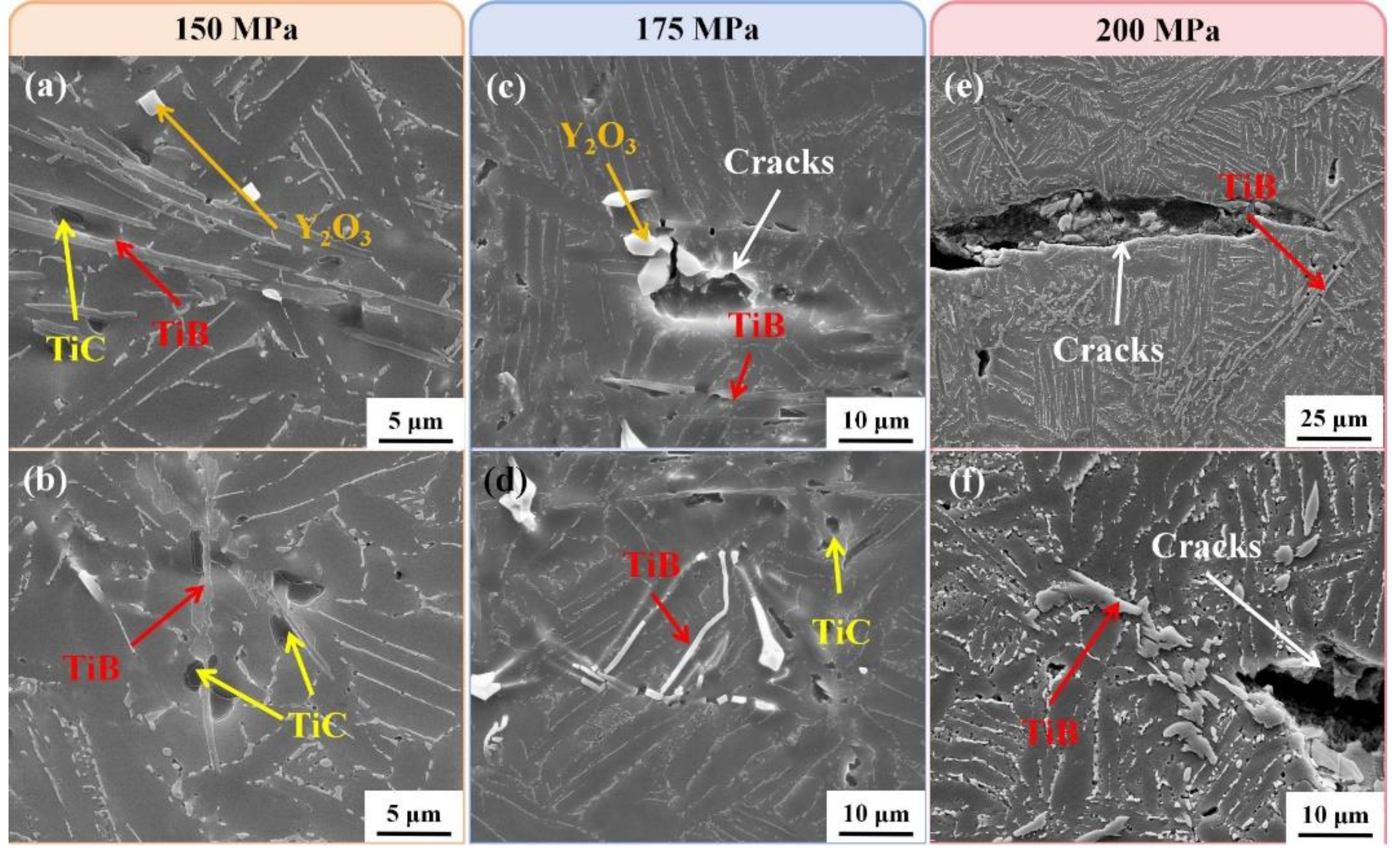
Figure 6.
Creep deformation of TMC under different stresses at 700 °C: (a,b) 150 MPa; (c,d) 175 MPa; (e,f) 200 MPa.
Figure 6.
Creep deformation of TMC under different stresses at 700 °C: (a,b) 150 MPa; (c,d) 175 MPa; (e,f) 200 MPa.
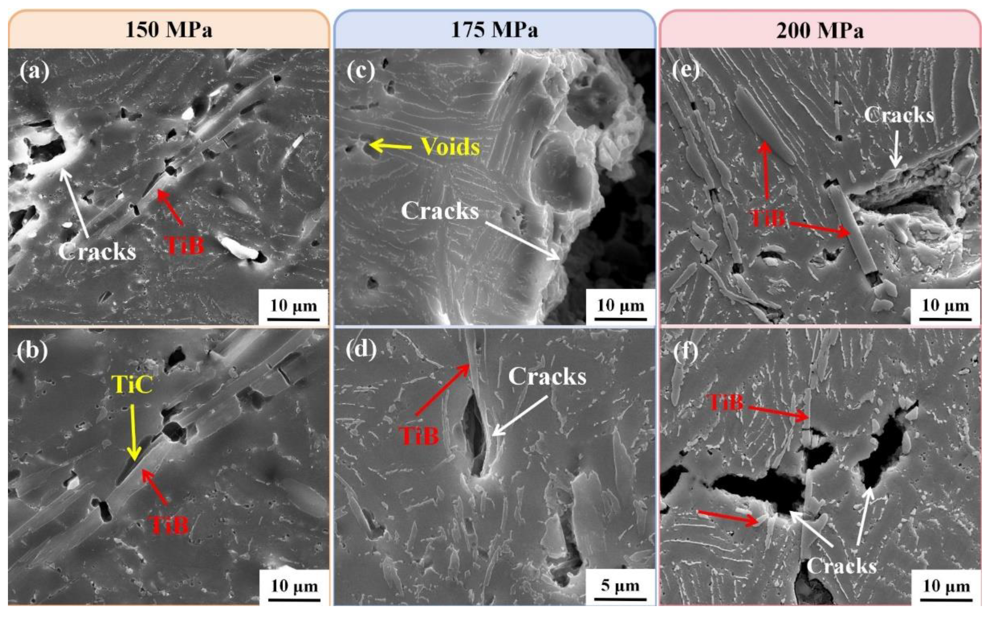
Figure 7.
Fracture morphology after creep under different conditions: (a) 650 °C/200 MPa; (b) 700 °C/150 MPa; (c) 700 °C/175 MPa; (d) 700 °C/200 MPa.
Figure 7.
Fracture morphology after creep under different conditions: (a) 650 °C/200 MPa; (b) 700 °C/150 MPa; (c) 700 °C/175 MPa; (d) 700 °C/200 MPa.
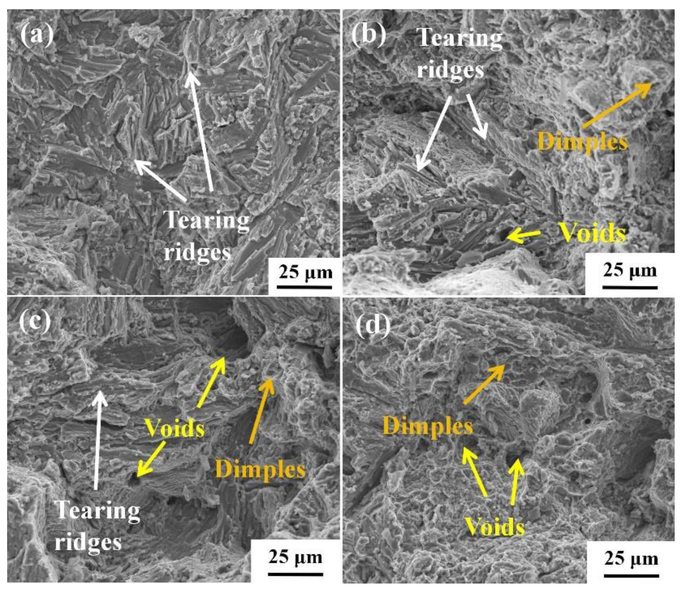
Figure 8.
Precipitation and energy spectrum analysis of silicide after creep at 650 °C/150 MPa: (a) morphological distribution of silicides; (b-e) distribution of elements Ti, Sn, Zr and Si, respectively.
Figure 8.
Precipitation and energy spectrum analysis of silicide after creep at 650 °C/150 MPa: (a) morphological distribution of silicides; (b-e) distribution of elements Ti, Sn, Zr and Si, respectively.
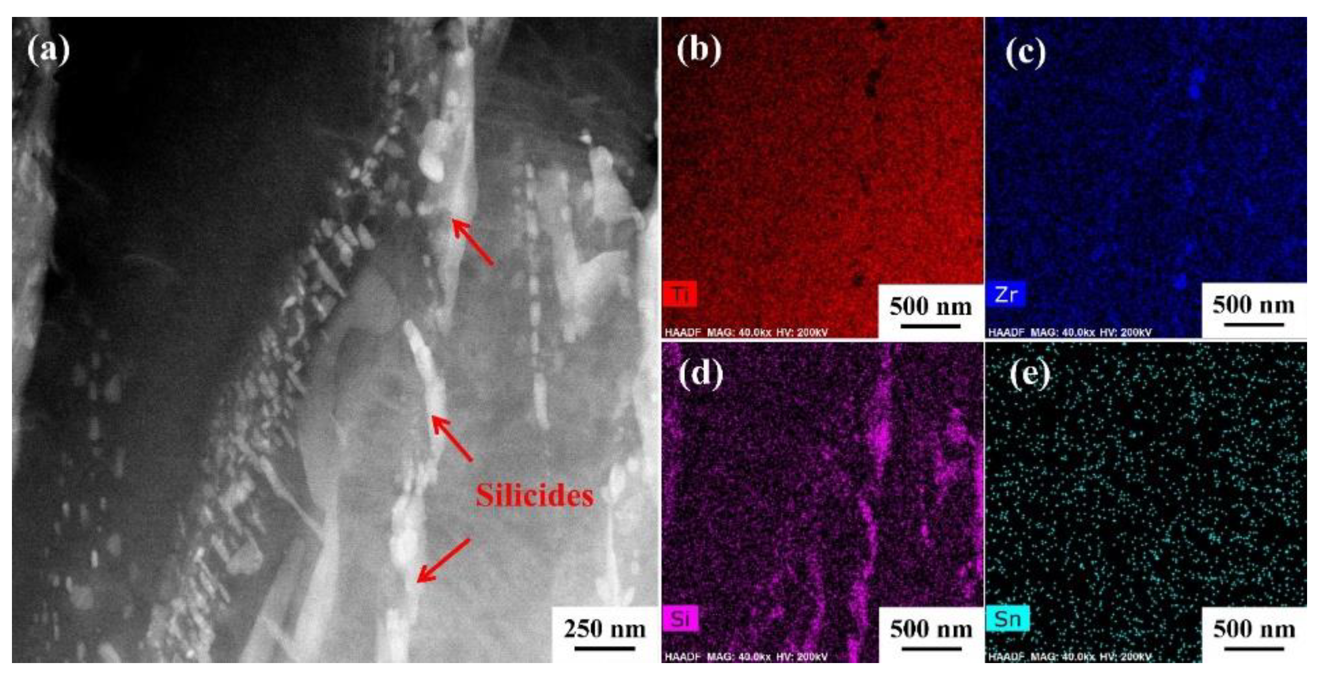
Figure 9.
Microstructure evolution of TMC during creep at 650 °C/150 MPa: (a,b) morphological distribution of silicides and their pinning effect on dislocations; (c,d) dissolution of β-Ti and its adjacent dislocations.
Figure 9.
Microstructure evolution of TMC during creep at 650 °C/150 MPa: (a,b) morphological distribution of silicides and their pinning effect on dislocations; (c,d) dissolution of β-Ti and its adjacent dislocations.
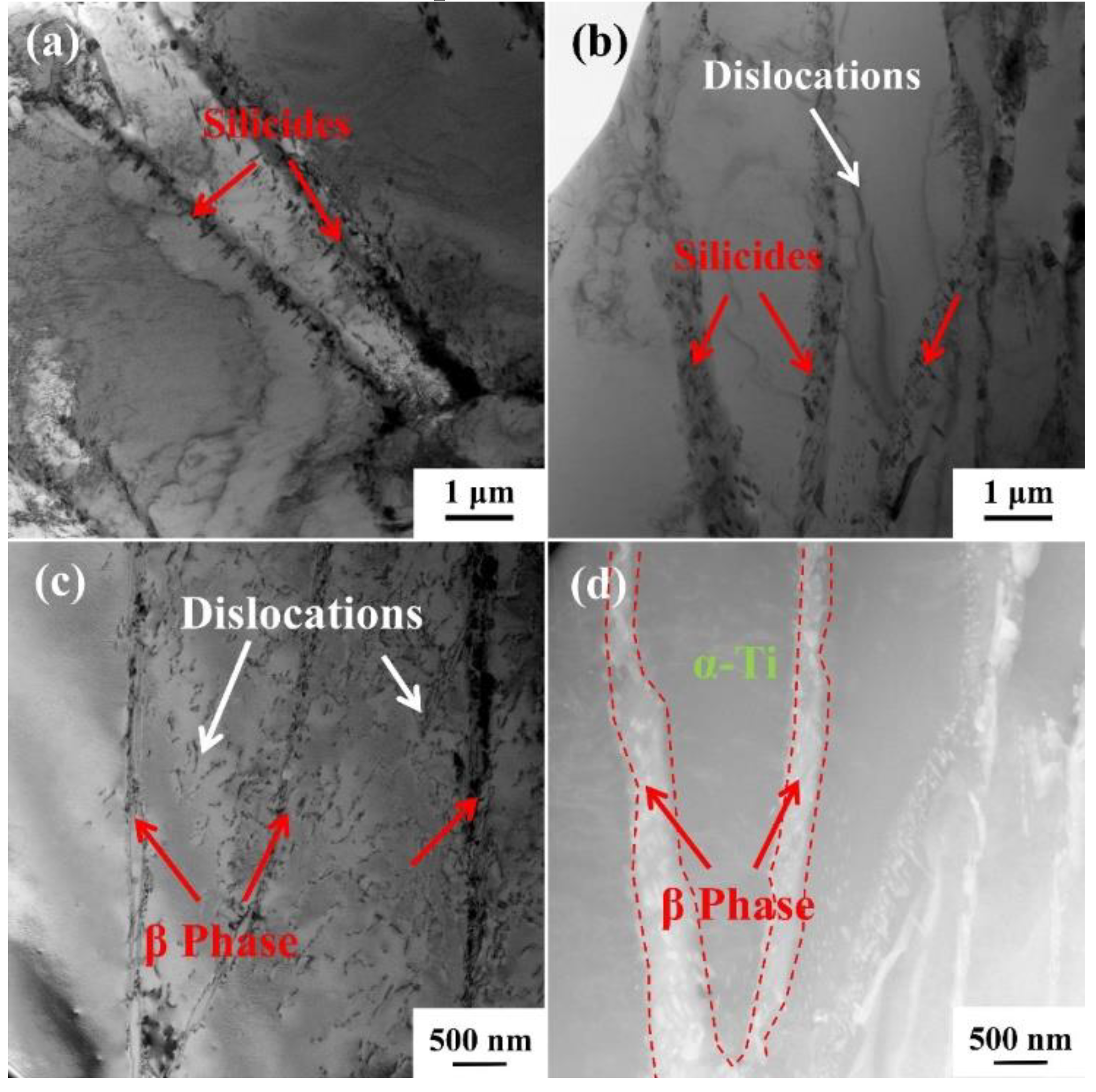
Figure 10.
Dissolution of β-Ti and silicates precipitation of TMC after creep at 700 °C/150 MPa: (a) the dissolution of the β-Ti and its surrounding silicides; (b) the pinning effect of silicides on dislocations.
Figure 10.
Dissolution of β-Ti and silicates precipitation of TMC after creep at 700 °C/150 MPa: (a) the dissolution of the β-Ti and its surrounding silicides; (b) the pinning effect of silicides on dislocations.
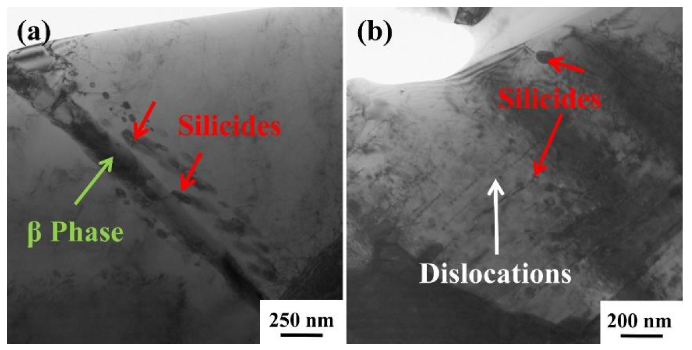
Figure 11.
Morphology of the reinforcements after creep under different conditions: (a,b) 650 °C/150 MPa; (c,d) 700 °C/150 MPa; (e,f) 650 °C/200 MPa.
Figure 11.
Morphology of the reinforcements after creep under different conditions: (a,b) 650 °C/150 MPa; (c,d) 700 °C/150 MPa; (e,f) 650 °C/200 MPa.
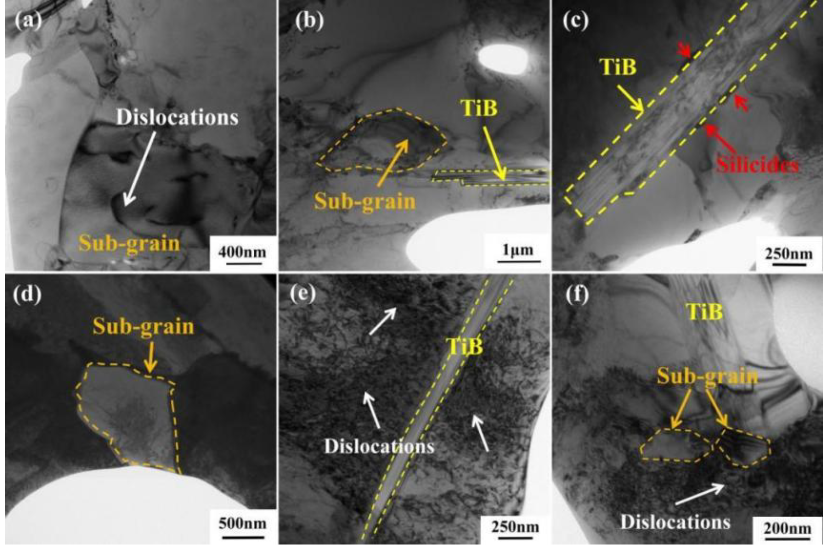
Figure 12.
Silicides near TiB after creep at 650 °C/200 MPa: (a) TiB and nearby silicides; (b-e) spectrum analysis of the corresponding region in (a); (f) TiB and its surrounding silicides; (g) high-resolution images of TiB and silicides and diffraction spots of silicides.
Figure 12.
Silicides near TiB after creep at 650 °C/200 MPa: (a) TiB and nearby silicides; (b-e) spectrum analysis of the corresponding region in (a); (f) TiB and its surrounding silicides; (g) high-resolution images of TiB and silicides and diffraction spots of silicides.
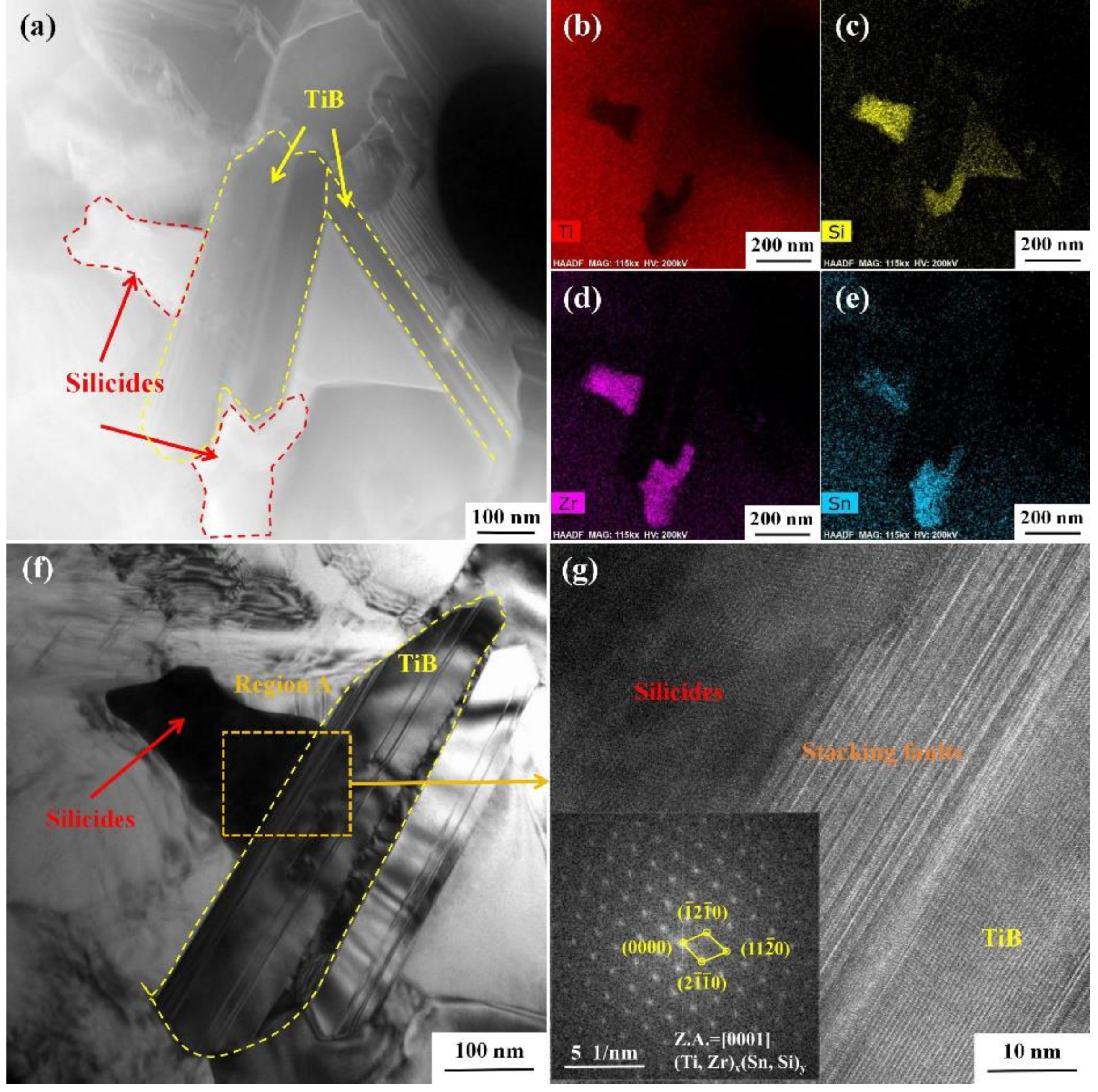

Table 1.
Creep properties of TMC under different conditions.
| Creep conditions | Strain/% | Steady state creep rate/s-1 | Creep time/h | Experimental state |
|---|---|---|---|---|
| 650 °C/150 MPa | 7.3 | 8.99×10⁻⁸ | 150.0 | Abort |
| 650 °C/175 MPa | 18.4 | 1.60×10⁻⁷ | 150.0 | Abort |
| 650 °C/200 MPa | 23.3 | 2.07×10⁻⁷ | 139.0 | Sample fracture |
| 700 °C/150 MPa | 47.0 | 1.19×10⁻⁶ | 31.8 | Sample fracture |
| 700 °C/175 MPa | 43.3 | 2.36×10⁻⁶ | 17.2 | Sample fracture |
| 700 °C/200 MPa | 38.5 | 2.74×10⁻⁶ | 14.6 | Sample fracture |
Disclaimer/Publisher’s Note: The statements, opinions and data contained in all publications are solely those of the individual author(s) and contributor(s) and not of MDPI and/or the editor(s). MDPI and/or the editor(s) disclaim responsibility for any injury to people or property resulting from any ideas, methods, instructions or products referred to in the content. |
© 2024 by the authors. Licensee MDPI, Basel, Switzerland. This article is an open access article distributed under the terms and conditions of the Creative Commons Attribution (CC BY) license (http://creativecommons.org/licenses/by/4.0/).
Copyright: This open access article is published under a Creative Commons CC BY 4.0 license, which permit the free download, distribution, and reuse, provided that the author and preprint are cited in any reuse.


