
Submitted:
03 December 2024
Posted:
04 December 2024
You are already at the latest version
Abstract
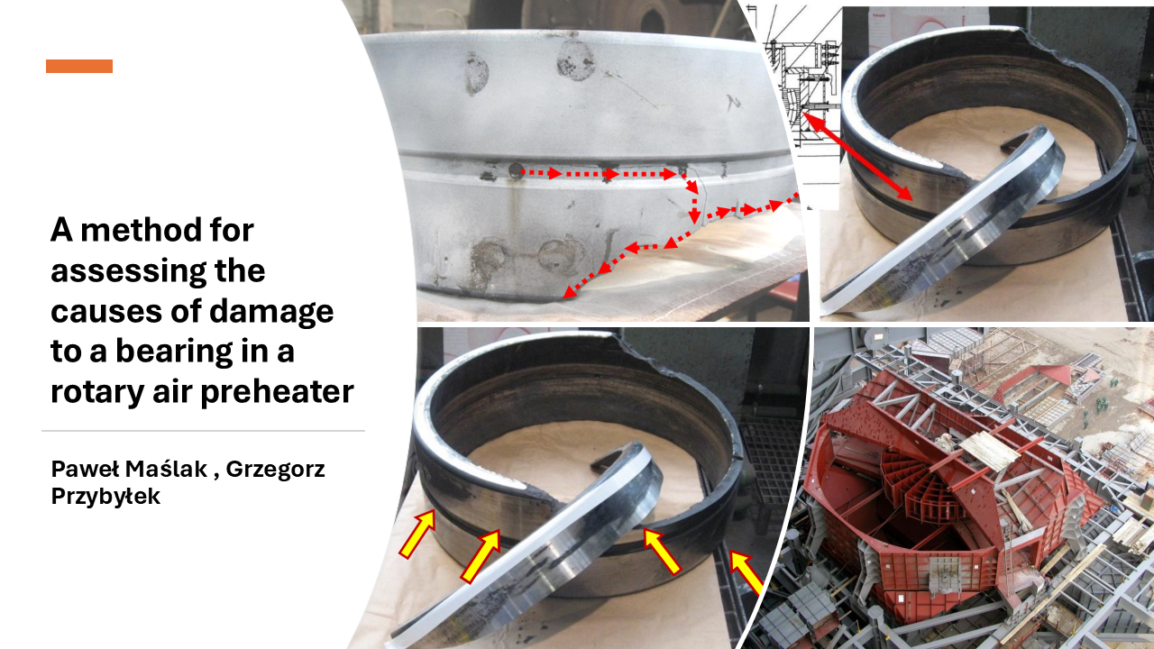
The article presents a method for identifying the cause of damage to a rotary air preheater on one of the fluidized bed boilers operating in a power plant. The bearing in question operates under harsh conditions with exhaust gas temperature reaching 287 [°C] and causing its casing to heat up intensively. It is therefore important to ensure that the bearing is constantly cooled by water, which lowers the operating temperature and thus extends its service life. Unfortunately, after a short period of operation, the upper double-row spherical roller bearing was damaged and the tests presented in the assessment method helped to determine the cause of damage to its casing.
Keywords:
bearing
; rotary air preheater
; damage analysis
1. Introduction
The rotary air preheater (LUVO, Figure 1) is one of the auxiliary devices of a steam generator and consists of a rotor and its drive, flanged connections, bearings, seals and a housing. Its task is to recover the temperature from the exhaust gases leaving the boiler and to heat up the air flowing in the opposite direction. The heated air is used to heat up the dust that enters the boiler through coal burners to ignition temperature. The heat is transferred through a vertical-axis rotor.
The rotor of the rotary air preheater consists of a sheet metal structure, which is the main part of the heat exchanger, and two end pins supported on self-aligning spherical roller bearings (transverse on top, tapered at the bottom). These pins are fixed to the sheet metal element with a screw connection.
The application of a self-aligning spherical roller bearing in the top section of the preheater has a number of advantages. The most important one is the insensitivity to misalignment of the shaft in relation to the housing resulting from shaft deflection. In addition, spherical roller bearings can support high radial loads as well as high axial loads in both directions [1,2]. The entire rotor is enclosed in a sealed casing with flanged connections on top and bottom for exhaust gases and air.
The preheater casing divides the device into two zones: the flue gas zone and the air zone. Usually the casing is divided into two sectors, but there are other possibilities depending on the required parameters, i.e. the required air heating temperature. The height and diameter of the rotor can also vary. The size of the device is chosen based on the the size of the steam generator and the efficiency of the preheater has a significant impact on the overall efficiency of the boiler.
The bearing component of the aforementioned rotor in the rotary air preheater consists of an axial thrust bearing underneath the rotor and a guide bearing on top of the rotor. The rotor guide bearing is a double-row spherical roller bearing with the outer diameter of 520 mm and an F7 fit, and the inner diameter of 340 mm with a g6 fit [3].
The damage to the self-aligning spherical roller bearing of the rotary air preheater is shown in Figure 2.
Bearings are critical components in various mechanical systems, facilitating smooth motion and reducing friction between moving parts. However, the integrity of bearings can be compromised due to various factors, leading to cracks and subsequent failure. In one power plant, after several years of operation there was an emergency shutdown of the preheater on a fluidized bed boiler due to damage to the top bearing.
2. State of Art
This summary examines research on bearing damage in industrial equipment, including wind turbines and rotary air preheaters. Bearing damage in rotary air preheaters is a critical issue that can lead to significant operational disruptions and maintenance costs. Understanding the causes and early detection methods for bearing damage is essential for maintaining the efficiency and reliability of these systems.
Monitoring vibration amplitude and temperature is crucial for detecting bearing issues, with values exceeding 4.5 mm/s and 70°C indicating potential problems [4]. Bearing damage can lead to significant operational disruptions, as seen in a power plant where gear failure caused a unit shutdown. Improper lubrication and installation procedures are common causes of bearing damage in compressors [5]. In wind turbines, main bearing replacements occur earlier than expected, with 10% replaced by 10.5 years and up to 25% by 20 years [6]. This paper provides a comprehensive review of the current theory and practice related to the main bearings used in wind turbines, including their design, operation, modeling, damage mechanisms, and fault detection. Spalling is the primary type of damage observed, often resulting from surface-initiated rolling contact fatigue. These findings highlight the importance of proper maintenance and monitoring to prevent bearing failures and extend equipment lifespan. This survey [7] collects the efforts to understand the sources and consequences of damage to babbitted industrial bearings, which operate by means of a hydrodynamic, or hydrostatic, film. Major individual damage types are discussed in the context of major damage categories.
The paper [8] examines the causes and mechanisms of bearing damage in aircraft gas turbine main shaft bearings, finding that the initial damage is often caused by surface defects and that the failure mechanism involves peeling and spalling of the bearing surface. An examination of approximately 200 bearing incidents in current aircraft engines has shown that damage in the bearing is initiated at the surface. The initial damage was produced by abrasive particles, dents, grinding scores, skidding, large carbides and corrosion pits. The first phase of the failure mechanism appeared to be by peeling, where microscopic regions about 0.13 mm (0.005 in) were removed from the surface, and the peels eventually developed into spalls. These mechanisms of failure are a consequence of the partial EHD lubrication utilized in these bearings, and the consequent sharing of the load by the asperities and the EHD film.
The paper [9] reviews traditional algorithms used to detect and diagnose faulty ball bearings in rotating machinery. This paper shows traditional signal processing algorithms used to detect and diagnose faults in ball bearings of heavy-duty milling machine tool spindle heads. Different kinds of faults have been created deliberately on the bearings of a test spindle head.
The paper [10] provides a comprehensive survey of theoretical and simulation approaches to understanding adhesive joint failures. This review, conducted within the framework of the CERTBOND initiative, focuses on methods applicable across aerospace, automotive, civil engineering, and other sectors. The authors examine nine models, including Classical Analytical Methods, Process Zone Methods, Linear Elastic Fracture Mechanics, the Virtual Crack Closure Technique, and the Cohesive Zone Method, among others. Each model is discussed in terms of methodology, required parameters, advantages, disadvantages, and specific industrial applications. The review highlights both strengths and limitations of these models in handling complex factors like crack propagation, environmental effects, and composite materials, providing a critical comparative analysis that guides future improvements in adhesive joint certification and application.
The paper [11] explores a method to assess bearing loads in hydraulic excavator drive systems. The authors develop a mathematical model to calculate the forces and moments experienced by the slewing bearings during operation. This model uses measurements of the excavator’s kinematic chain and hydraulic pressures to compute load vectors under real-world conditions. By analyzing these loads, particularly during the digging phase, the study provides insights to optimize bearing selection for durability and performance. This research contributes valuable data for improving excavator design, ensuring structural integrity and operational efficiency.
The paper [12] investigates the thermal behavior of threaded spindle bearings in CNC machines. By focusing on ZKLN type bearings, the study uses finite element analysis (FEA) to model heat generation and dissipation due to friction. The iterative process combines analytical methods and FEA simulations to optimize the thermal load calculations. Results reveal that while housing materials slightly affect heat distribution, managing thermal loads is essential for accurate machine performance, as heat can induce deformations that compromise precision. This work contributes a systematic approach for enhancing spindle bearing design in high-speed applications.
This summary examines failure analyses in various industrial applications. Cracking in air preheater components was attributed to microstructure degradation and high thermomechanical stress [13]. API X70 steel, used in ethanol pipelines, showed susceptibility to stress corrosion cracking (SCC) and corrosion fatigue, particularly in notched specimens and under staggered constant load conditions [14]. A comprehensive review of failure case studies highlighted issues such as buckling in pressurized vessels, fatigue failures in welded structures, and environmentally assisted cracking in various materials and components [15]. In a liquid sulfur recovery unit, a 304 stainless steel heat exchanger failed due to pitting corrosion, intergranular corrosion, and SCC caused by sulfuric acid and chloride ions [16]. These studies emphasize the importance of understanding material behavior, environmental factors, and stress conditions in preventing industrial failures.
For wind turbines, premature main bearing failures primarily result from rolling contact fatigue, often requiring replacements much earlier than expected. Aircraft turbine bearings frequently fail due to surface defects and spalling initiated by abrasives and corrosion. A reviewed paper on ball bearing fault detection discusses traditional signal processing methods, while another paper investigates adhesive joint failures and presents various modeling techniques to predict crack propagation under industrial conditions.
Cracked bearings represent a significant challenge in mechanical systems, with implications for performance, maintenance, and safety. By understanding the causes of bearing cracks and implementing effective mitigation strategies, engineers and maintenance personnel can enhance the reliability and longevity of bearing systems. Overall, these studies emphasize that proactive maintenance and optimized design, supported by analytical and simulation models, are crucial for extending equipment lifespan and reliability across industries.
3. Chemical Composition Analysis
At the beginning of research, the chemical composition was analyzed with a spectrometer to determine the type of material used for the bearing [17,18]. All elements of the bearing were tested, i.e.: inner ring, damaged outer ring, spherical roller elements and cage (Figure 3).
Table 1 shows the identified alloying elements and their percentage in the material of the damaged outer ring of the bearing.
Based on the percentage composition of elements it was determined that the material that best matches this composition is AISI 6150 alloy steel (1.8159/51CrV4) [18].
During X-ray analysis, the spectrometer detected exceedances for some alloying elements contained in this steel (marked red - Table 1). When analyzing the different percentages of individual elements, it should be noted that each bearing manufacturer uses his own proprietary technology to manufacture bearing parts. This is why small exceedances in the percentage of alloying elements for the identified steel grade are acceptable.
The material used for the outer ring of the bearing is highly wear-resistant. It has very good impact strength and is highly resistant to dynamic loads (higher-class heat treatment). Therefore, this material is commonly used in loaded machine parts such as shafts, gears, gearboxes and rolling elements operating at high temperatures [18]. Moreover, during production, individual elements of bearings, i.e. outer and inner ring and rolling elements are subjected to 100% UT inspection (ultrasonic testing).
4. Measurement of Raceway Hardness
The second parameter that is important in determining the steel grade is hardness. When carrying out hardness measurements, the Vickers method was used (Figure 4). The tests were performed on two parts of the damaged ring in 10 points that were uniformly distributed along the circumference of the bearing. The number of measurements at each point ranged from 6 to 10 and the obtained hardness range was from 61.8 HRC to 62.1 HRC.
According to the literature, corrosion-resistant bearing steels are obtained through the process of hardening (820-840)°C and low tempering 180°C (1÷2 h), which produces a hardness of 62.5 HRC [18]. Therefore, the measured values confirm that the outer ring of the bearing in the rotary air preheater has undergone proper heat treatment.
5. Non-Destructive Testing
When assessing the technical condition of structures or when identifying causes of damage to components of devices or machines, non-destructive testing methods are often used [19,20].
5.1. Visual Testing
The basic method of non-invasive assessment is visual testing, which was carried out on all elements of the damaged bearing [21,22]. The visual inspection of the outer ring revealed a discontinuity in the material of the outer raceway, which passes through the oil hole and groove. The visual inspection of the fracture resulting from the separation of a fragment of the casing revealed three types of fracture surfaces:
In addition, formations of non-ferrous metals were found on the fracture surface, which means that during the failure, a part of the ring must have come into contact with the cage that is made of brass (Figure 7).
Other phenomena caused by the temporary overloading of the bearing included the flaking of material, denting in the separated fragments of rolling elements, seizures and crevice corrosion, particularly visible on the inner raceway of the bearing (Figure 8). Additionally, tests revealed damage to the side surfaces of the outer ring (Figure 9).
When the rolling elements of the damaged bearing were examined, most of them had cavities, chipping and spalling (Figure 10a).
The damage to the inner ring of the air preheater bearing caused by excessive contact pressures, through excessive bearing deflection, resulted in the grinding of the surface of a significant number of rollers - there are "fresh" signs of material flaking (Figure 10b).
The aforementioned damage may have already started while the bearing was in operation and not as a direct result of a failure because the LUVO bearing is subject to heavy and low cycle loads.
In addition, when operating in severe conditions (elevated temperatures), the bearing sustains so-called secondary damage. Figure 11 shows an example of such damage in the form of fretting corrosion on the outer ring.
Fretting corrosion is commonly encountered when operating conditions cause deformations of bearing seats under heavy loads. It can be black (as recorded in this case), red or reddish-brown. Over time, advanced corrosion leads to improper contact between the mating surfaces of elements and consequently to bearing damage.
5.2. Magnetic Particle Testing
In order to determine the extent of damage to the outer and inner raceways of the bearing, non-destructive tests were carried out using the magnetic particle method method (MT). During the inspection, the wet magnetic particle testing method with a permanent magnet was used. To detect the flux leakage field, magnetic particles in an aerosol suspension were sprayed on the tested component during magnetization. The test area of the part was cleaned of oil and painted with contrast paint to improve the sensitivity of particle defectographs [23,24,25,26].
Based on the test results it was possible to determine the geometric form and the size of the crack on the outer ring of the bearing (Figure 12).
6. Conclusions
The material of the bearing was tested for chemical composition and hardness. By measuring the percentage of individual alloying elements in the steel, it was determined that the material used to build the bearing satisfies the standards and complies with the documentation of the device manufacturer. The hardness of the material was measured in order to verify that the correct heat treatment process was selected for the bearing components. The obtained hardness values (~ 62 HRC) confirmed that correct heat treatment was used for the bearing.
Based on the abovementioned results of material tests it was determined that the failure was not caused by poor quality of the supporting bearing.
Non-destructive testing was the step in determining the cause of bearing damage. The test results identified damage in the form of a crack in the bearing’s outer ring, material flaking and seizures of the inner raceway and fractures of its side surface. In addition, the visual inspection revealed the presence of fretting, which propagated during operation and became one of the main causes of damage to the rotary air preheater bearing. Fretting usually occurs when the fit is insufficient/too loose and there is relative motion between the bearing ring and housing. Relative motion is usually caused by shape inaccuracies or shaft deflection and causes small pieces of the material to split off from the surface of the seat in the housing. These pieces oxidize quickly upon contact with air. The corrosion on the outer ring (Figure 11) produces local shape imperfections on the surface of the bearing seat - the volume of iron oxide is larger than that of pure steel. The natively concave and convex bearing seat resulted in insufficient fit between the bearing ring and the seat surface along its width, which is why it deflected under load, resulting in a fatigue crack on the circumference of the ring raceway - the ring cracked at its weakest point, in the oil groove. The likely direction of propagation and the resulting loss of material integrity of the outer ring is shown in Figure 15.
The fretting, which resulted in the failure of the air preheater, could have also been caused by human error when the bearing seat was mounted.
To sum up, as a result of the performed tests, it was determined that the direct cause of failure of the rotary air preheater support was fretting, which occurred due to a design error - the fit was insufficient and/or there where manufacturing flaws - incorrect mounting of the bearing in the housing.
Author Contributions
Conceptualization, P.M and G.P.; methodology, P.M and G.P.; investigation, P.M and G.P.; resources, P.M and G.P.; data curation, X.X.; writing—original draft preparation, P.M and G.P.; writing—review and editing, P.M and G.P.; visualization, P.M and G.P.; supervision, P.M and G.P. All authors have read and agreed to the published version of the manuscript.
Funding
This research received no external funding.
Institutional Review Board Statement
Not applicable.
Data Availability Statement
MDPI Research Data Policies at https://www.mdpi.com/ethics.
Conflicts of Interest
The authors declare no conflicts of interest.
References
- Smolnicki, T. Fizykalne aspekty koherencji wielkogabarytowych łożysk tocznych i odkształcalnych konstrukcji wsporczych, Oficyna Wydawnicza Politechniki Wrocławskiej, Wrocław 2002. (in polish).
- Smolnicki, T. Large-diameter rolling bearings. Global and local problems (in Polish). Wrocław: Wrocław University of Technology Publishing House, 2013.
- http://www.skf.com 25.10.2024.
- Hartono, B.; Sutisna S., P. Analisa kerusakan bearing suspention preheater fan berbasis data temperatur dan vibrasi, AME (Aplikasi Mekanika dan Energi): Jurnal Ilmiah Teknik Mesin 2018.
- Hart, E.; Raby, K.; Keller, J.; Sheng, S.; Long, H.; Carroll, J.; Brasseur, J.; Tough, F. Main Bearing Replacement and Damage - A Field Data Study on 15 Gigawatts of Wind Energy Capacity, NREL July 2023.
- Hart, E.; Clarke, B.; Nicholas, G.; Kazemi Amiri, A. K.; Stirling, J.; Carroll, J. R.; Dwyer-Joyce, R.; McDonald, A.; Long, H. A review of wind turbine main bearings: design, operation, modelling, damage mechanisms and fault detection. Wind Energy Science 2020, 5, 105–124. [Google Scholar] [CrossRef]
- Branagan, L. Survey of Damage Investigation of Babbitted Industrial Bearings, Engineering, Materials Science. Lubricants 2015, 3, 91–112. [Google Scholar] [CrossRef]
- Averbach, B.; Bamberger, E. Analysis of bearing incidents in aircraft gas turbine mainshaft bearings. Tribology Transactions 1991, 34. [Google Scholar] [CrossRef]
- Bediaga, I.; Mendizabal, X.; Arnaiz, A.; Munoa, J. Ball bearing damage detection using traditional signal processing algorithms. IEEE Instrumentation & Measurement Magazine 2013, 16, 20–25. [Google Scholar] [CrossRef]
- Tserpes, K.; Barroso-Caro, A.; Carraro, P.A.; Beber, V.C.; Floros, I.; Gamon, W.; Kozłowski, M.; Santandrea, F.; Shahverdi, M.; Skejić, D.; Bedon, C.; Rajčić, V. A review on failure theories and simulation models for adhesive joints. The Journal of Adhesion 2022, 98, 1855–1915. [Google Scholar] [CrossRef]
- Jovanović, V.; Janošević, D.; Petrović, N. Experimental determination of bearing loads in rotating platform drive mechanisms of hydraulic excavators. Facta Universitatis Series: Mechanical Engineering 2014, 12, 157–169. [Google Scholar]
- Krstić, V.; Milčić, D.; Milčić, M. A thermal analysis of the threaded spindle bearing assembly in numerically controlled machine tools. Facta Universitatis Series: Mechanical Engineering 2018, 16, 261–272. [Google Scholar] [CrossRef]
- Lv, F.; Hu, X.; Ma, C.; Yang, B.; Luo, Y. Failure analysis on cracking of backing plate of lifting lug for air preheater. Engineering Failure Analysis 2020, 109, 104395. [Google Scholar] [CrossRef]
- Santos, E.A.D.; Giorgetti, V.; Souza Junior, C.A.D.; Marcomini, J.B.; Sordi, V.L.; Rovere, C.A.D. Stress corrosion cracking and corrosion fatigue analysis of API X70 steel exposed to a circulating ethanol environment. International Journal of Pressure Vessels and Piping 2022, 200. [Google Scholar] [CrossRef]
- Jones, D.R.H. Failure analysis case studies II : a sourcebook of case studies selected from the pages of Engineering failure analysis 1997-1999. Engineering, Environmental Science 1998. [Google Scholar]
- Yang, X.; Liu, M.; Liu, Z.; Du, C.; Li, X. Failure analysis of a 304 stainless steel heat exchanger in liquid sulfur recovery units. Engineering Failure Analysis 2020, 116, 104729. [Google Scholar] [CrossRef]
- PN-EN ISO 683-17:2015-01 Stale do obróbki cieplnej, stale stopowe i stale automatowe. Część 17: Stale na łożyska kulkowe i wałeczkowe. (in polish).
- Luty W.: Metaloznawstwo i obróbka cieplna stali łożyskowych, WNT 1980. (in polish).
- PN-EN 1330-2 Badania nieniszczące. (in polish).
- PN-EN 13018 Badania nieniszczące – Badania wizualne. (in polish).
- PN-EN 12454 Odlewnictwo – Badania wizualne nieciągłości powierzchniowych. (in polish).
- PN-EN ISO 9934-1 Badania nieniszczące – Badania magnetyczno - proszkowe. Część 1: Zasady ogólne. (in polish).
- PN-EN 1369 Odlewnictwo – Badania magnetyczno – proszkowe. (in polish).
- PN-EN 10228-1 Badania nieniszczące odkuwek stalowych – Badania magnetyczno – proszkowe. (in polish).
- PN-EN 10246-12 Badania nieniszczące rur stalowych. (in polish).
- PN-EN 10288-4 Badania nieniszczące odkuwek stalowych – Badania ultradźwiękowe odkuwek ze stali nierdzewnych, austenitycznych i austenityczno-ferrytycznych. (in polish).
Figure 1.
The installation of a rotary air preheater on the steam generator.
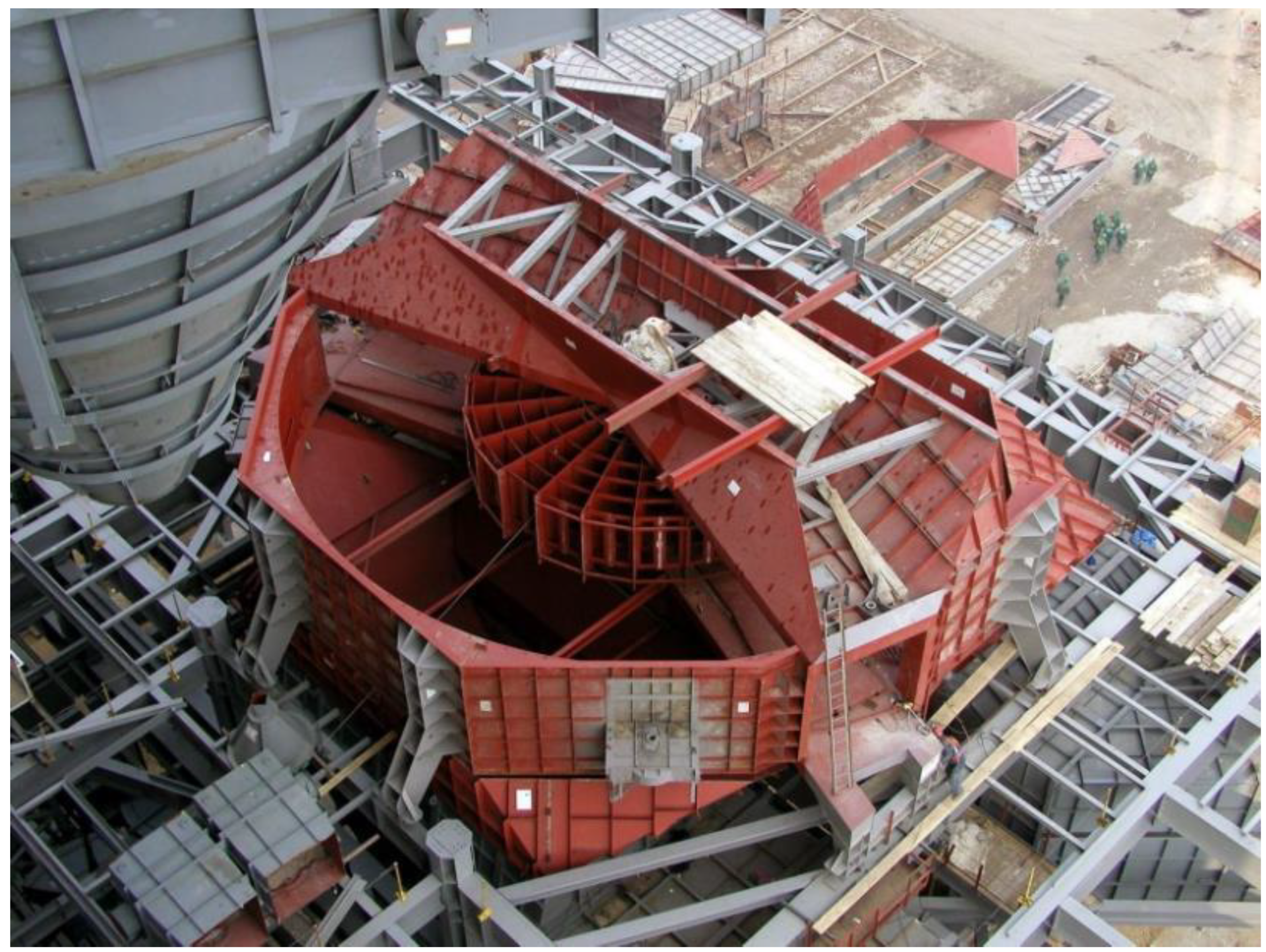
Figure 2.
Damaged self-aligning spherical roller guide bearing of the rotary air preheater.
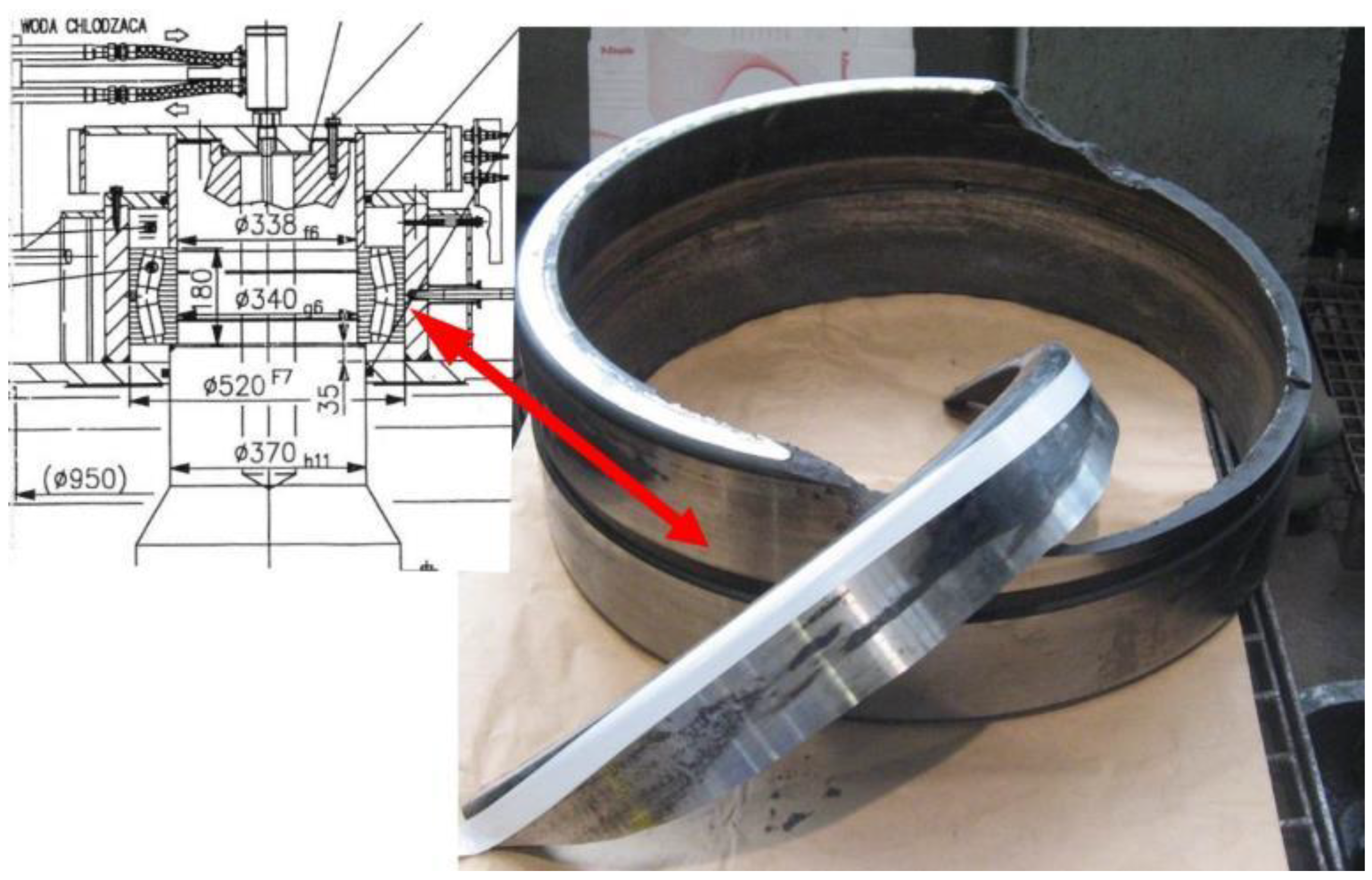
Figure 3.
Damaged self-aligning.
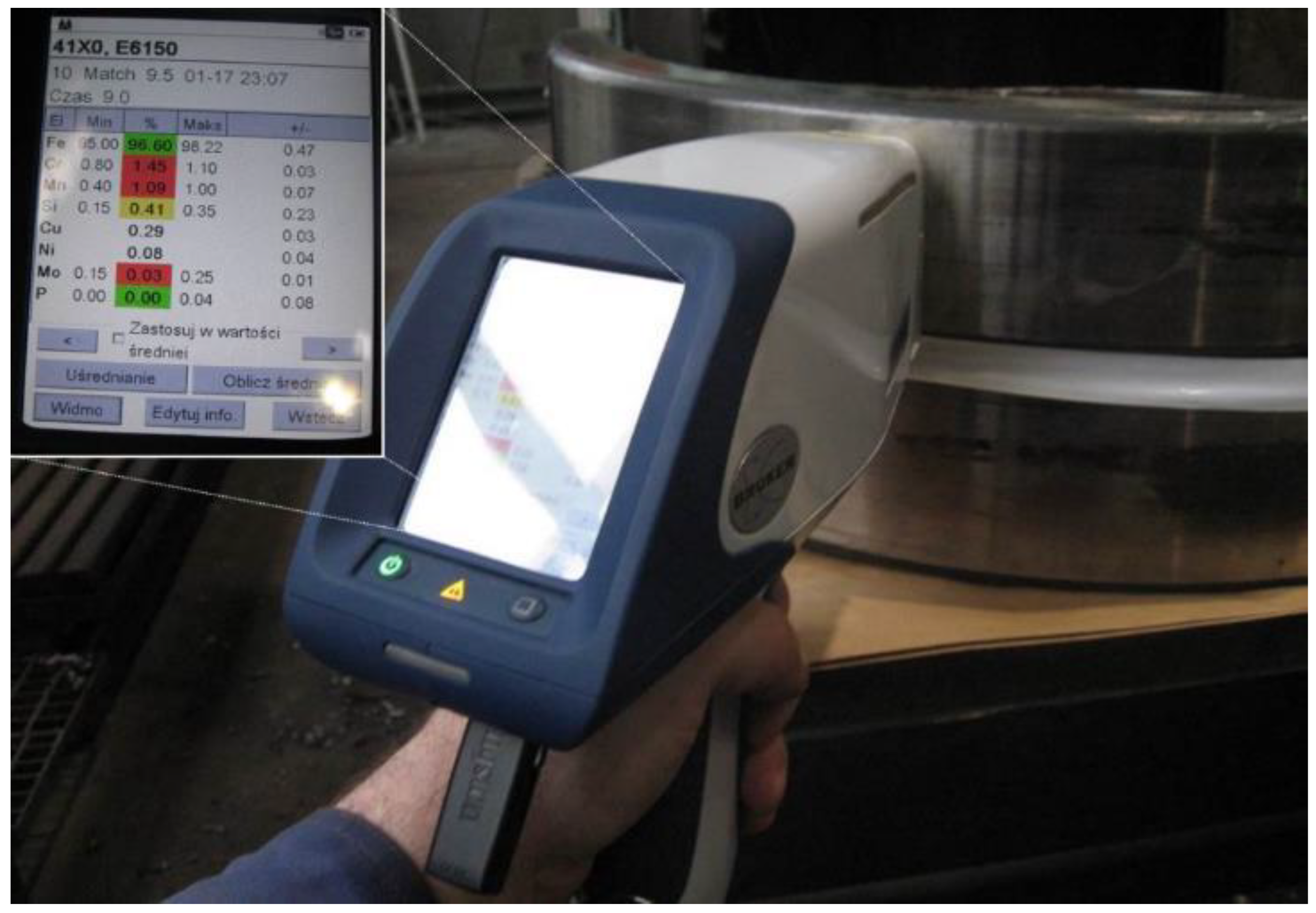
Figure 4.
The measurement of hardness of the damaged outer ring of the bearing using the COMPUTEST S.C. hardness meter.
Figure 4.
The measurement of hardness of the damaged outer ring of the bearing using the COMPUTEST S.C. hardness meter.

Figure 5.
Fracture of the outer ring of the bearing. Fatigue, conchoidal zone (red arrows) and shear, residual zone (yellow arrows).
Figure 5.
Fracture of the outer ring of the bearing. Fatigue, conchoidal zone (red arrows) and shear, residual zone (yellow arrows).
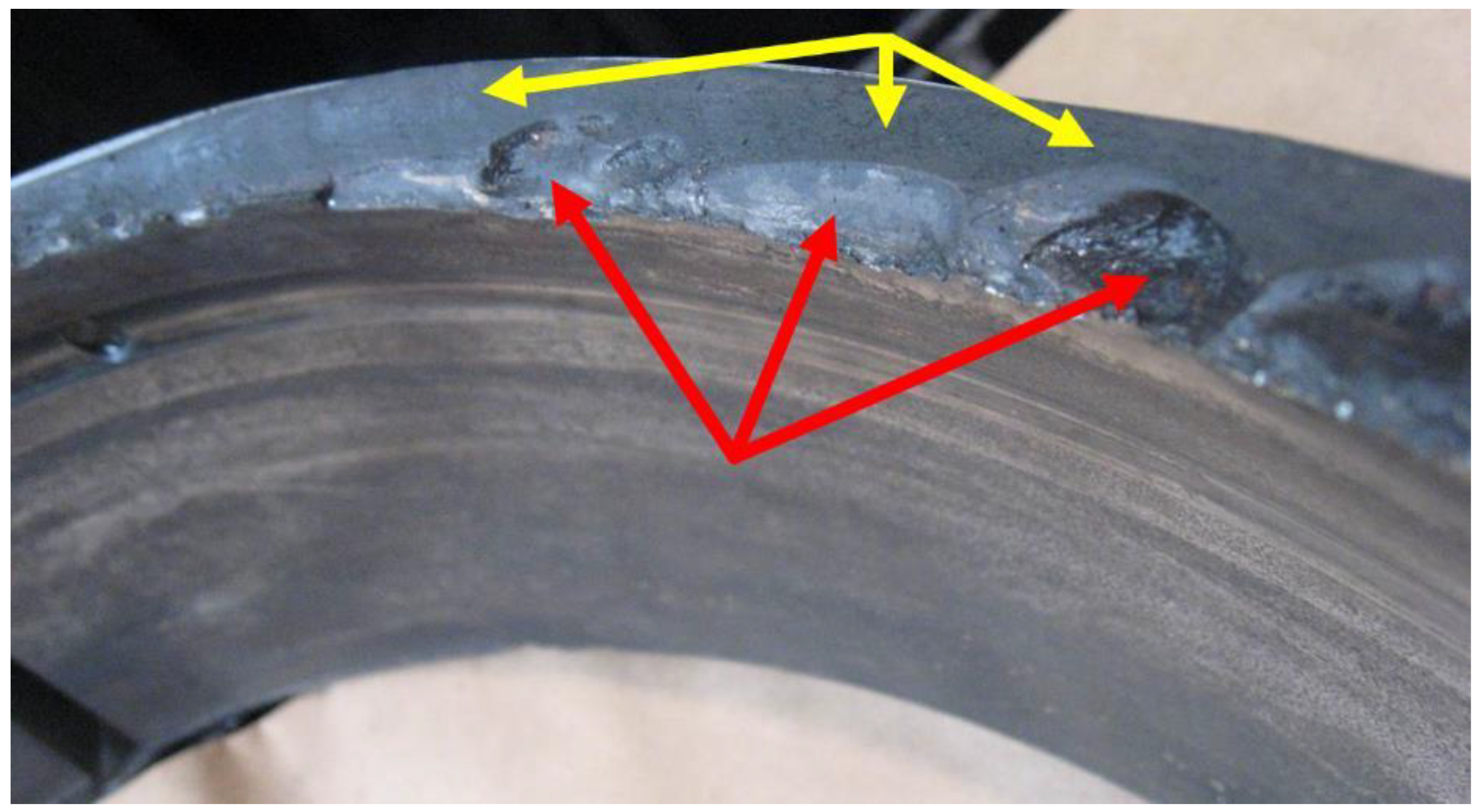
Figure 6.
Zone of contact pressure between the separated part of the raceway and the rest of the raceway.
Figure 6.
Zone of contact pressure between the separated part of the raceway and the rest of the raceway.
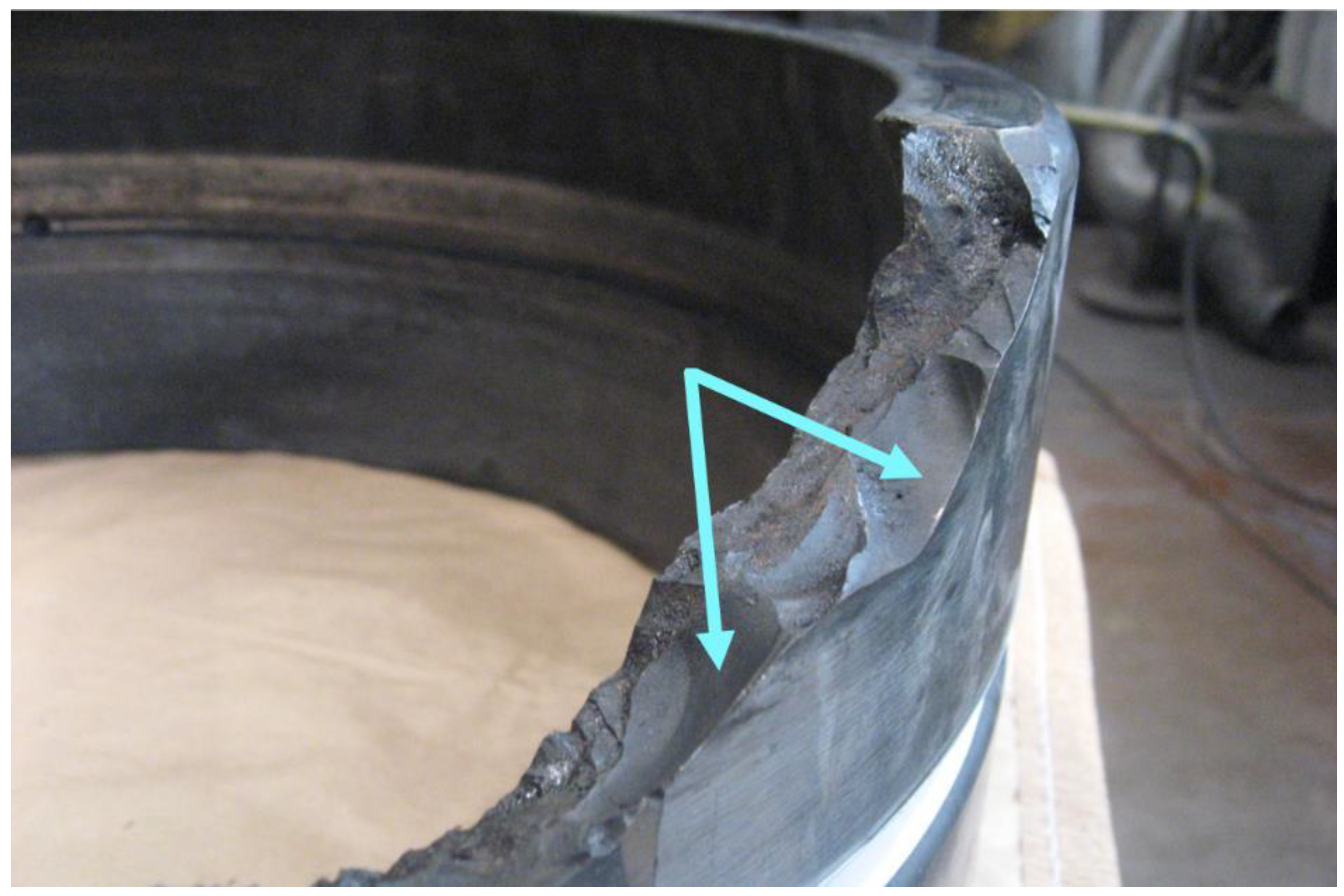
Figure 7.
Traces of brass which the bearing cage is made of.
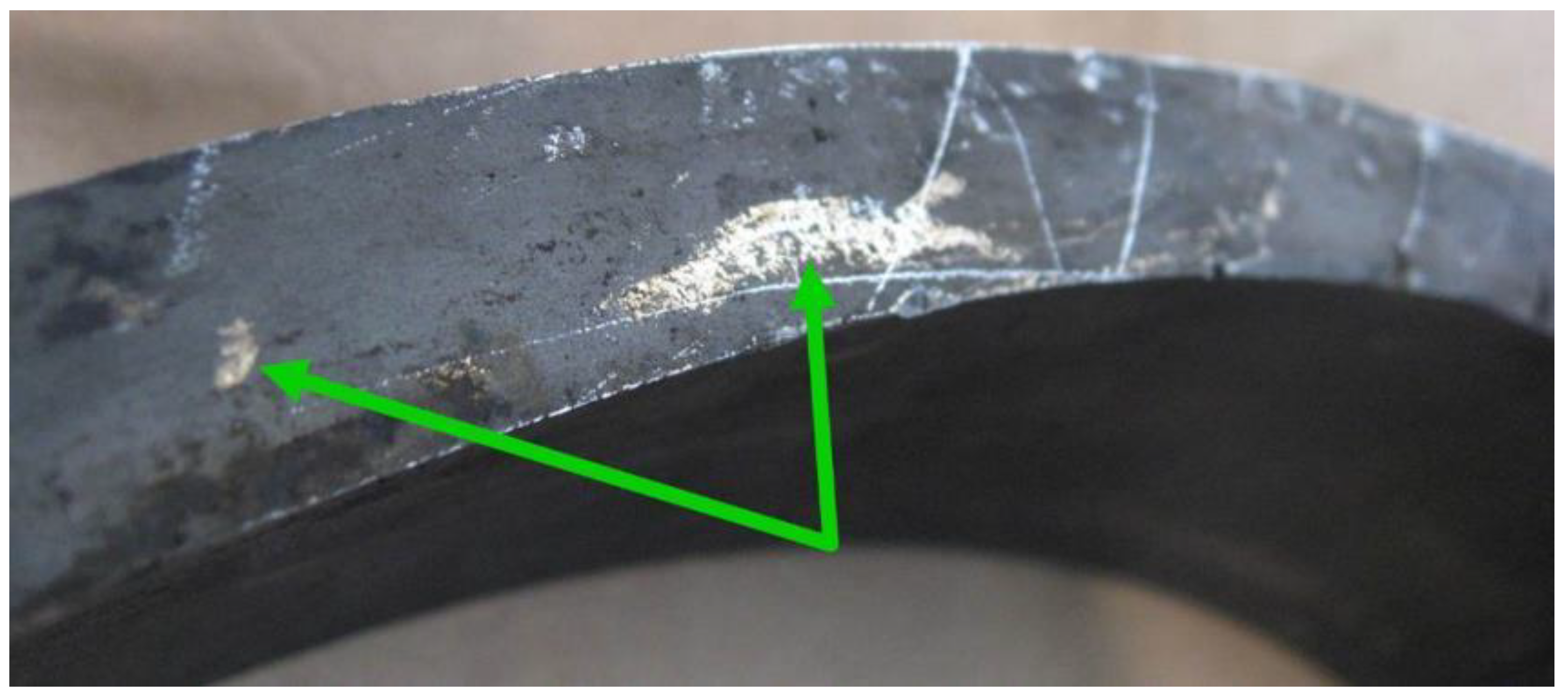
Figure 8.
Signs of peeling and damage to the raceway and side surfaces of the inner ring.
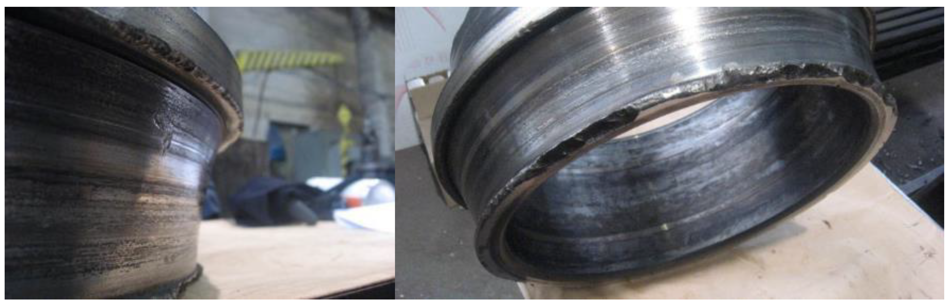
Figure 9.
Signs of damage to the side surfaces of the outer ring.
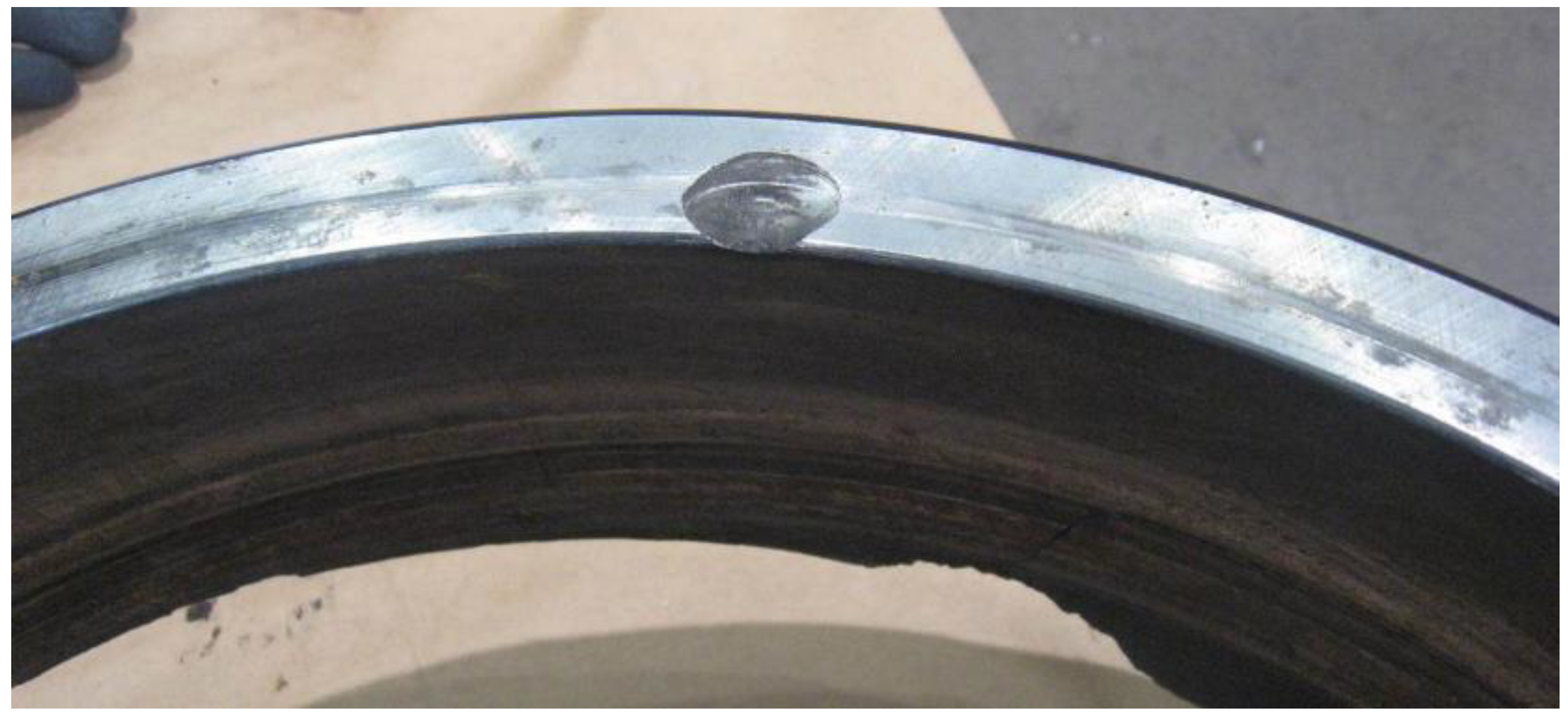
Figure 10.
Damage to the bearing's rolling elements: (a) chipped contact surface between the rolling element and the raceway, (b) chipped edge of the rolling element.
Figure 10.
Damage to the bearing's rolling elements: (a) chipped contact surface between the rolling element and the raceway, (b) chipped edge of the rolling element.
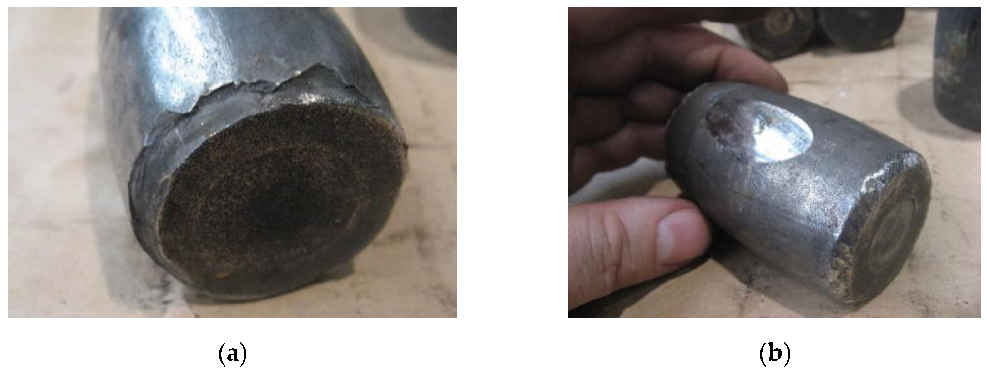
Figure 11.
Fretting corrosion on the bearing’s outer ring mating surface.
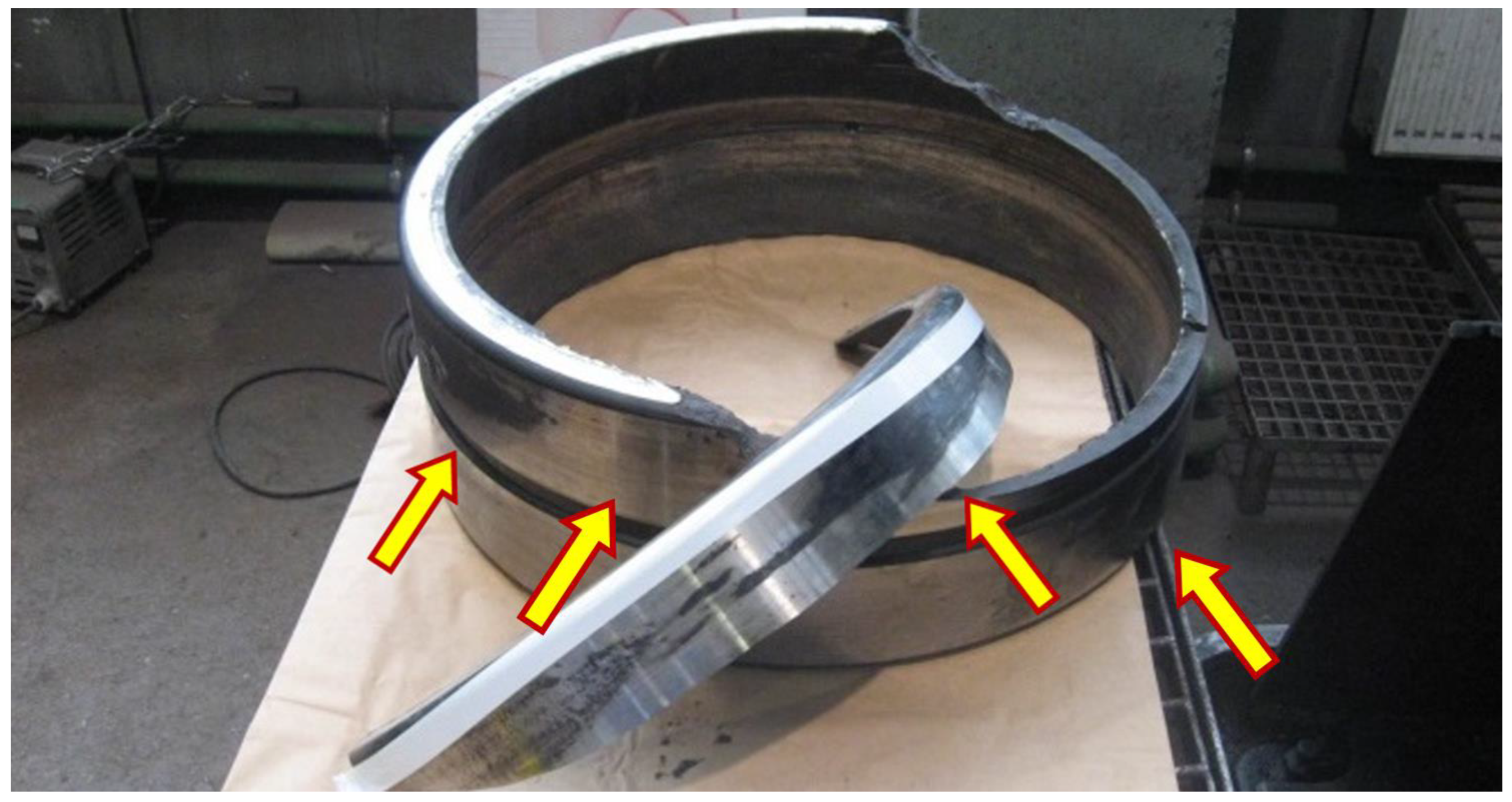
Figure 12.
Size of material discontinuity.
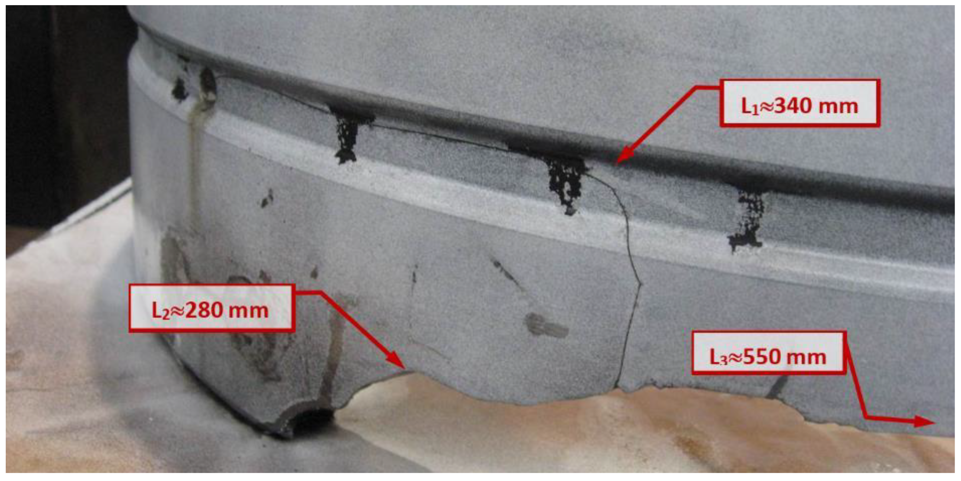
Figure 15.
Direction of crack propagation.
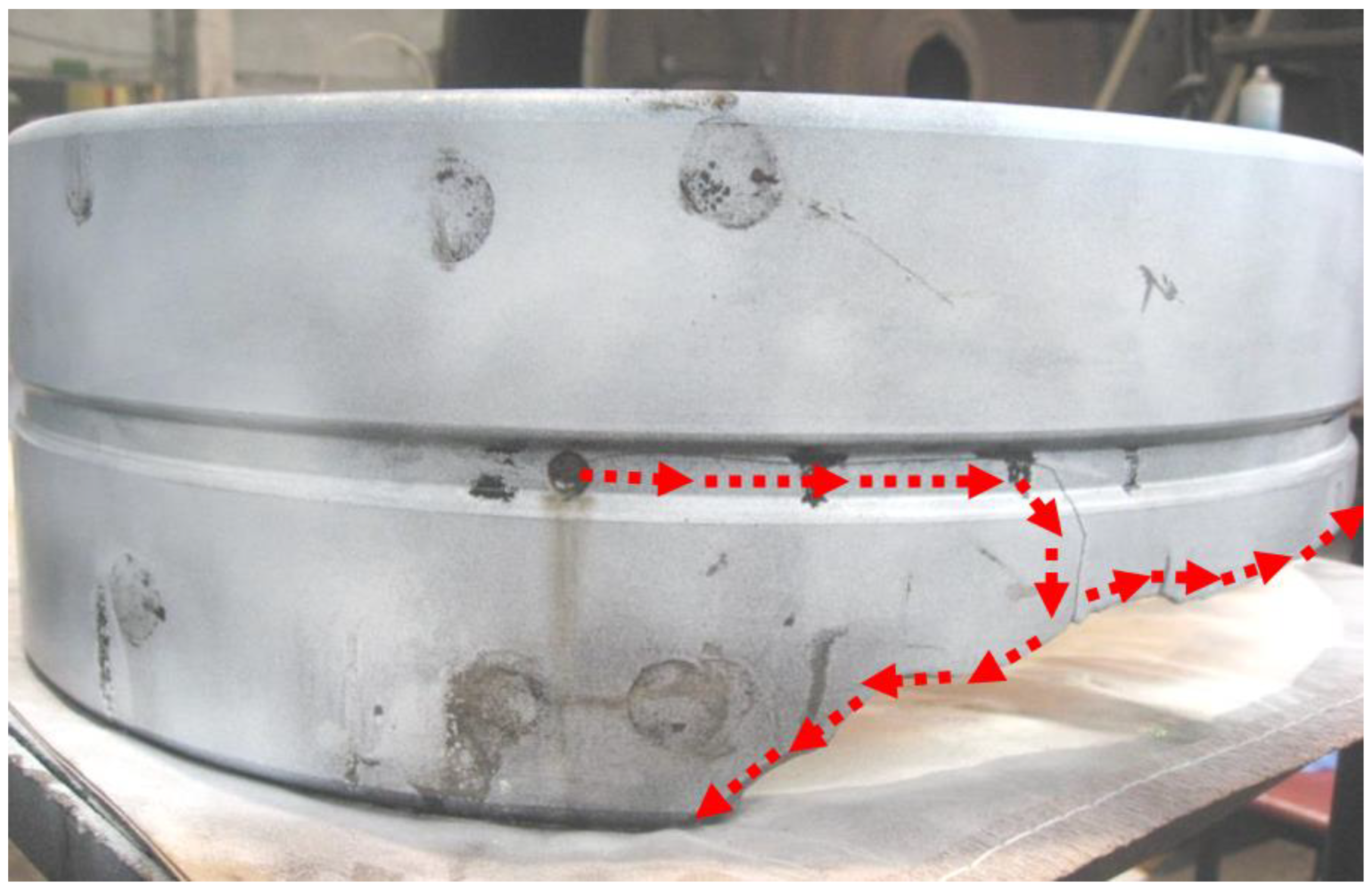

Table 1.
Percentage composition of elements in the material of the outer ring of the bearing.
| Element | Fe | Cr | Mn | Si | Cu | Ni | Mo | P |
| Max | 98.22 | 1.10 | 1.00 | 0.35 | - | - | 0.25 | 0.04 |
| [%] | 96.60 | 1.45 | 1.09 | 0.41 | 0.29 | 0.08 | 0.03 | 0.00 |
| Min | 95.00 | 0.80 | 0.40 | 0.15 | - | - | 0.15 | 0.00 |
Disclaimer/Publisher’s Note: The statements, opinions and data contained in all publications are solely those of the individual author(s) and contributor(s) and not of MDPI and/or the editor(s). MDPI and/or the editor(s) disclaim responsibility for any injury to people or property resulting from any ideas, methods, instructions or products referred to in the content. |
© 2024 by the authors. Licensee MDPI, Basel, Switzerland. This article is an open access article distributed under the terms and conditions of the Creative Commons Attribution (CC BY) license (http://creativecommons.org/licenses/by/4.0/).
Copyright: This open access article is published under a Creative Commons CC BY 4.0 license, which permit the free download, distribution, and reuse, provided that the author and preprint are cited in any reuse.


