Preprint
Article

This version is not peer-reviewed.

Effect of Filler Density on the Mechanical Properties of Natural PEEK 450 Processed by FDM

A peer-reviewed article of this preprint also exists.

Submitted:

03 December 2024

Posted:

04 December 2024

You are already at the latest version

Abstract

In the present investigation, the mechanical properties of natural PEEK 450 processed by 1 additive manufacturing and applying fused deposition modeling (FDM) are investigated. Mechanical 2 characterization was performed through destructive testing, following ASTM D638-14, ASTM D695- 3 15 and ASTM D790-10 standards. Specimens were designed in CAD software and printed with 4 controlled infill densities of 40%, 70% and 100%, using a rectilinear pattern. The results showed that 5 an increase in infill density improves mechanical strength and stiffness, but reduces ductility and 6 energy absorption capacity. These findings offer crucial information for optimizing infill density in 7 the manufacturing of high-strength components for industrial and biomedical applications. As a 8 result, practical guidelines are provided for the design of medical devices, such as implants, achieving 9 an appropriate balance between mechanical performance and material efficiency.

Keywords: 
;  ;  ;  ;  

1. Introduction

Industrial applications of polymeric materials as more economical and environmentally friendly alternatives are growing at a sustained rate. In the specific case of polyether-ether-ketone (PEEK), one of the areas of application is medicine, for the manufacture of custom medical devices (for example, anatomical models, cutting guides, and bone implants).
Research on PEEK in additive manufacturing has grown considerably in recent years. However, despite the advances, there are still areas that require further analysis.
The current status of 3D printed PEEK that has been used, in addition to medicine, in chemistry, aerospace and electronics, is reported, for example in [1]. This review concludes that PEEK printing uses Fused Filament Fabrication (FFF) or Fused Deposition Modelling (FDM) printers. And that most applications are still in the research phase.
It is already known that, due to its good properties, 3D-printed PEEK also has great potential as a replacement for implants made of other metal alloys. [2] reports on FDM printed specimens (without specifying what kind of specimens were used) and their evaluation of dimensional accuracy, crystallinity and mechanical properties. Mechanical properties increased with elevated chamber temperature and post-print annealing. It is concluded that many factors affect the quality of 3D printed PEEK and that new regulations, for example, from the Food and Drug Administration (FDA), for 3D printed products for this manufacturing process are necessary to ensure the safety and effectiveness of biomedical applications.
The article [3] analyses the use of PEEK as a printing material to explore the combined effect of multiple factors: different printing temperatures, printing directions, printing routes and layer thicknesses. The work investigates how these factors influence the tensile strength, flexural strength, crystallinity and grain size of printed FDM pieces. The goal was to attain comparable results to those achieved through injection moulding. Among the main findings, it was observed that the greater the tensile strength of the printed sample, the greater the uniformity in the grain size and the greater the crystallinity of the material.
In [4] a classification of the mechanical properties of the PEEK family polymers is proposed, and a comparison is made with other polymers to determine their versatility in biomedical applications. The authors report a maximum tensile stress for medical grade PEEK-OPTIMA, without specifying how the mechanical tests were performed. In another work [5] the authors discuss the performance of direct tests on PEEK dental prostheses, manufactured by injection. The work [6] reports on the application of PEEK-OPTIMA structures for the manufacture of implant-supported CAD-CAM prostheses. In this case, a certain value is obtained for the maximum compressive stress, and the application falls within dentistry.
In the paper [7], FDM was employed to fabricate PEEK samples for performing tensile tests to investigate the relationship between various thermal processing conditions in the FDM process, such that the raster angle, nozzle temperature, ambient temperature, post-heat treatment temperature after FDM, and the mechanical properties of pure PEEK material. In this work, the mechanical properties of the printing filament are assumed, according to ISO 527 regulations; but it is not clarified about the tested specimens either.
In [8] standard PEEK parts were 3D printed, by FDM method too, for bending and compression tests. Nozzle diameter, nozzle temperature and printing speed were involved. The density and dimensional accuracy of the printed parts were evaluated according to the ISO standard 178 for three-point bending test specimens in the shape of small bars, and ISO standard 604 for the compression tests cylindrical specimens.
3D-printed PEEK is known to exhibit excellent flexural and tensile strength. In the study [9], The authors found that changes in temperature and printing speed affect the material mechanical properties. Additionally, the bio-inert nature of PEEK can make adhesive bonding difficult. Options are also offered to improve bond strength. A comprehensive overview of the research progress on the mechanical properties of PEEK for dental applications is provided.
In a systematic review by Moby [10], optimal printing parameters were established for FDM 3D-printed PEEK elements with mechanical properties suitable for dental restorations. The selected studies were difficult to compare due to the variability of the printing parameters and the types of PEEK. It seems interesting to use a high infill rate, a high chamber temperature close to that of the printing temperature and a heat post-treatment to obtain 3D PEEK elements presenting properties adapted to use as dental restorations.
Some of the remaining challenges to successfully performing FDM of PEEK are addressed in [11]. In this research, finite element analysis (FEA) is applied to simulate the melting conditions and fluidity of the polymer in a flow channel, to establish the necessary parameters to achieve prints with good surface quality and better mechanical properties. FDM experiments were conducted to investigate the effects of printing temperature, speed, and layer thickness on the mechanical properties, microstructure, and surface quality of printed parts. It is suggested that a heating temperature higher than 440   ° C , a printing speed of 20 m m / s and a printing layer thickness of 0.1 m m can improve the density of PEEK parts, reduce internal defects and strengthen the bond between the printed layers and with the filling filament. The tensile strength was measured at room temperature and the specimens were prepared according to the tensile test method and GB/T 1040-92 standard.
In most of the articles mentioned above (except [11]) the conditions for performing mechanical tests are not specified (taking into account those works in which results on mechanical characterization are reported). There is no clarity on the type of printed parts and specimens being tested or the grade of PEEK used, whether it is related to medical or industrial.
In a recent study, Wu et al. investigated how layer thickness and raster angle affect the mechanical properties of PEEK 3D printed parts, finding that a layer thickness of 300 μ m and a raster angle of 0 / 90 offered the optimal properties for certain industrial applications [12]. However, this study does not specifically address how infill density, one of the key parameters in FDM, affects the mechanical properties of PEEK.
On the other hand, Liu et al. studied the dynamic mechanical and thermomechanical properties of FDM-processed PEEK, evaluating the material behavior under tensile loading and observing the fracture morphology. Their results showed a direct relationship between the printing process and the fracture morphology, but they also omit the specific impact of the infill density on the mechanical properties, a crucial aspect for material optimization in practical applications [13].
Despite these advances, there is a significant gap in the literature regarding the influence of infill density on the mechanical properties of FDM-processed PEEK, especially in terms of its performance in biomedical and industrial applications. Although research has been conducted on the behavior of 3D printed PEEK, the relationship between infill density and mechanical properties has not been thoroughly described; this constitutes a limitation to the optimization of the design and manufacturing of customized devices that require a balance between mechanical strength, material efficiency, and functionality.
The present research focuses on how the density of filler used in the 3D printing process applying FDM technology can affect the mechanical properties of specimens manufactured with natural PEEK 450 (also known as industrial grade PEEK). This is in consideration of the diverse findings reported in the specialized literature regarding the parameters that need to be controlled in the 3D printing process. The tensile, compression, and bending tests conducted adhere to regulations for studying thermoplastic polymeric materials. The results obtained aid in understanding the performance of customized medical devices.

2. Materials and Methods

For the development of this research, ASTM standards were applied to ensure the rigour and reproducibility of the mechanical tests carried out on natural PEEK test specimens. The selection of these standards was based on the need to characterize the material’s properties in a standardized manner and to ensure the comparability of the results. ASTM D638-14 was used for tensile testing; this standard accurately assesses the strength and modulus of elasticity of polymers under tension, providing critical information on the material’s ability to withstand stretching forces before failing. ASTM D695-15 was applied for compression testing, essential for characterizing PEEK’s strength under compressive loads, particularly in applications where the material is subject to crushing forces. Finally, ASTM D790-10 was applied for bending tests, to evaluate the behaviour of PEEK against loads that generate bending stresses; a key aspect for applications that require resistance to both deformation and bending.
The material used was natural Polyether-ether-ketone 450 (PEEK), a high-performance polymer known for its thermal and mechanical resistance, making it suitable for industrial and biomedical applications. The specimens were manufactured by additive manufacturing, using the fused deposition modelling (FDM) technique; this allowed the impact of this manufacturing method on the mechanical properties of the material to be evaluated. The FDM technique was used for 3D printing, and challenges such as the possible anisotropy of the material and the influence of printing parameters such as temperature, speed, and layer orientation on the final properties of the specimens were addressed.

2.1. CAD Models

For the test specimens manufacture, CAD modelling was performed to ensure adequate dimensional accuracy and to ensure compliance with the requirements of the corresponding ASTM standards. The test specimens were designed using 3D modelling software, taking into account the geometric specifications necessary for bending, compression and tensile tests.
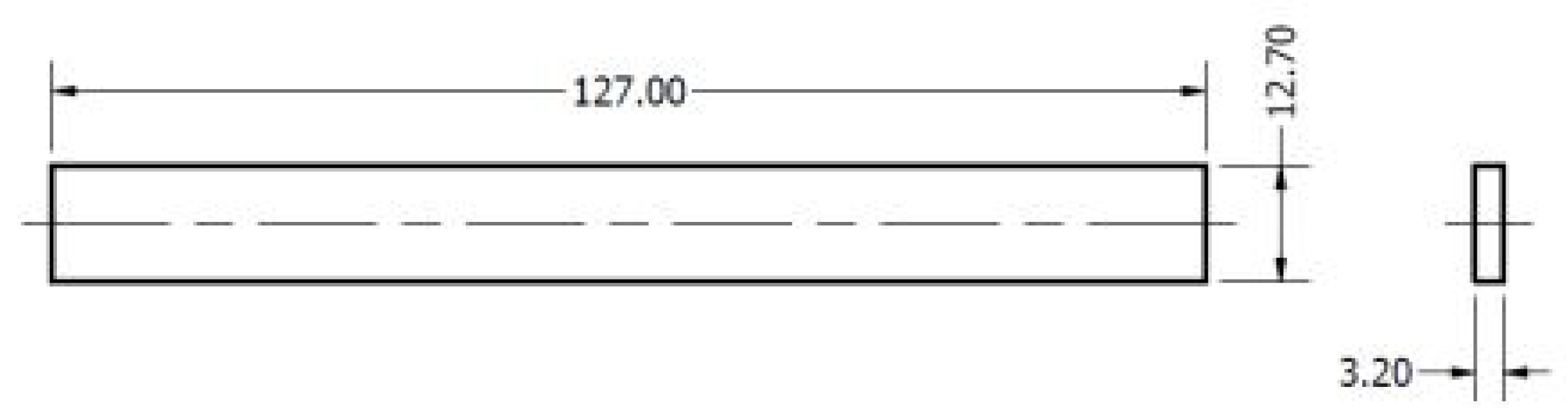
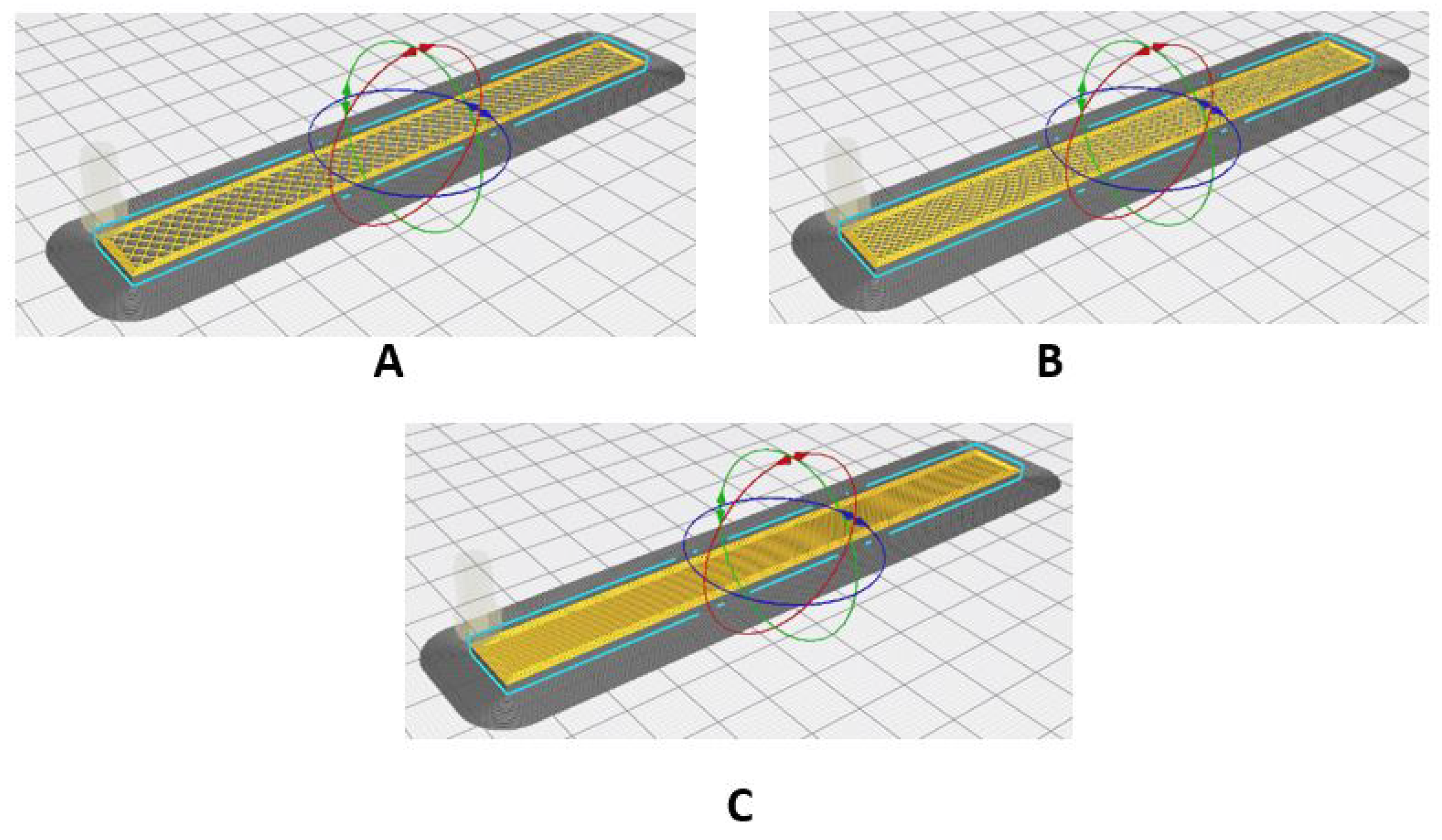
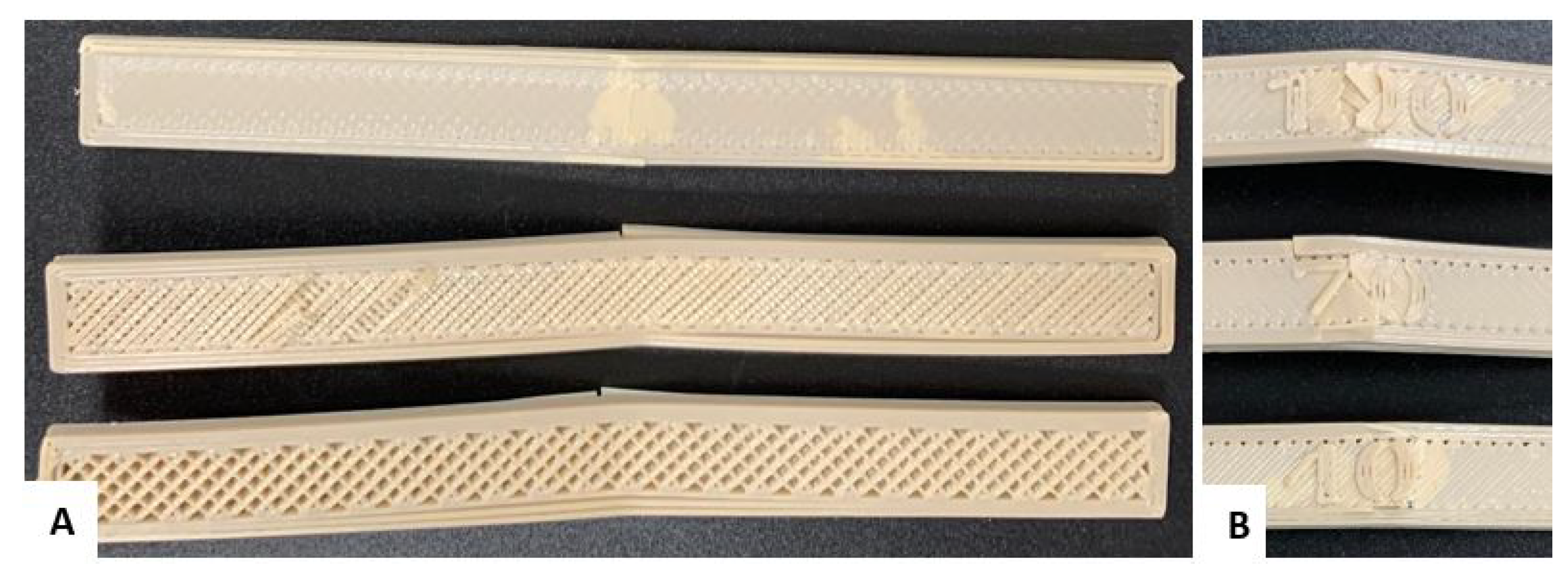
  • Flexural Test Specimen (ASTM D790-10)[14]: The CAD model of the flexural test specimen was designed with a length of 127 mm, a width of 12.7 mm, and a thickness of 3.2 mm. This rectangular geometry ensures that during the test a homogeneous distribution of stresses is generated along the cross-section, allowing for an accurate analysis of the flexural strength of the material (Figure 1)
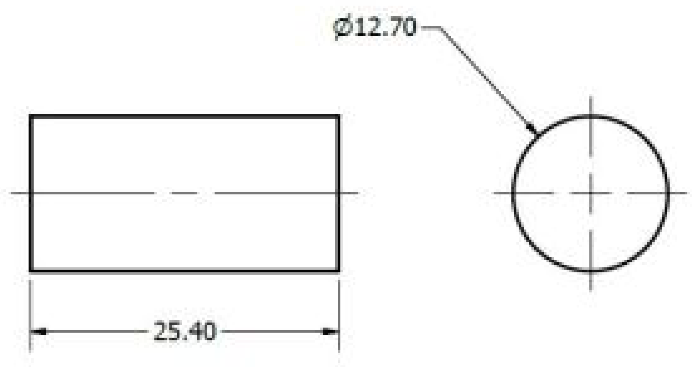
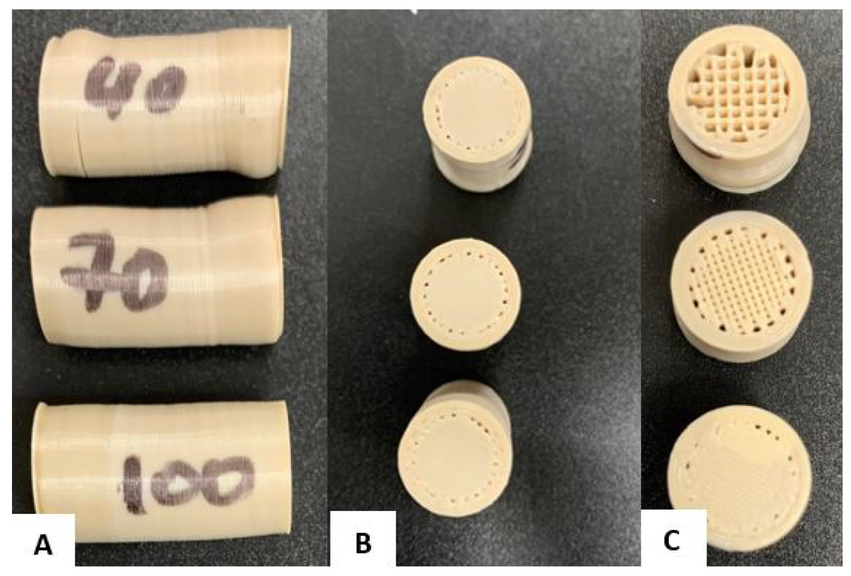
  • Compression Test Specimen (ASTM D695-15)[15]: The compression specimen was modelled as a cylinder, with a height of 25.4 mm and a diameter of 12.7 mm. This geometry allows for adequate load stability, minimizing undesirable effects, such as buckling, during testing. The cylindrical design is ideal for ensuring that the load is distributed evenly across the cross-section (Figure 2)
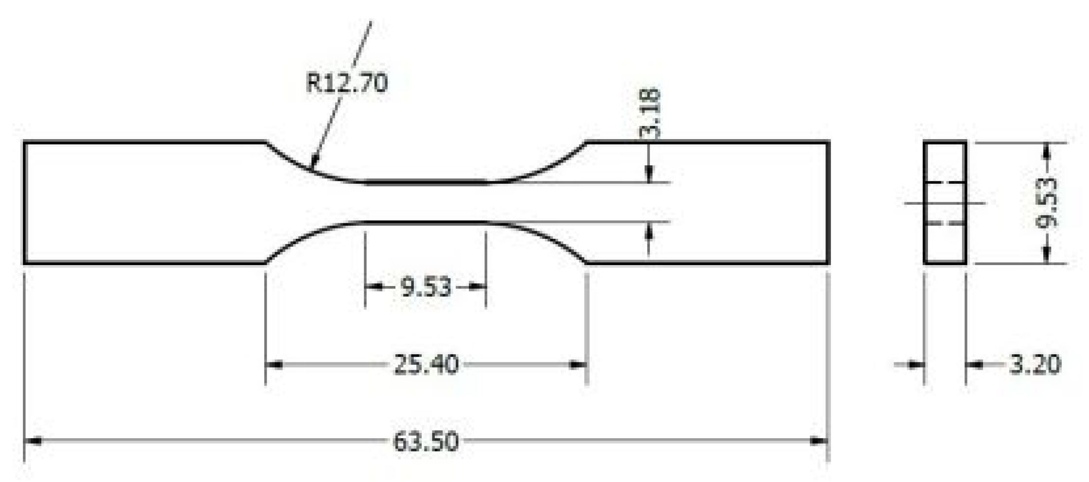
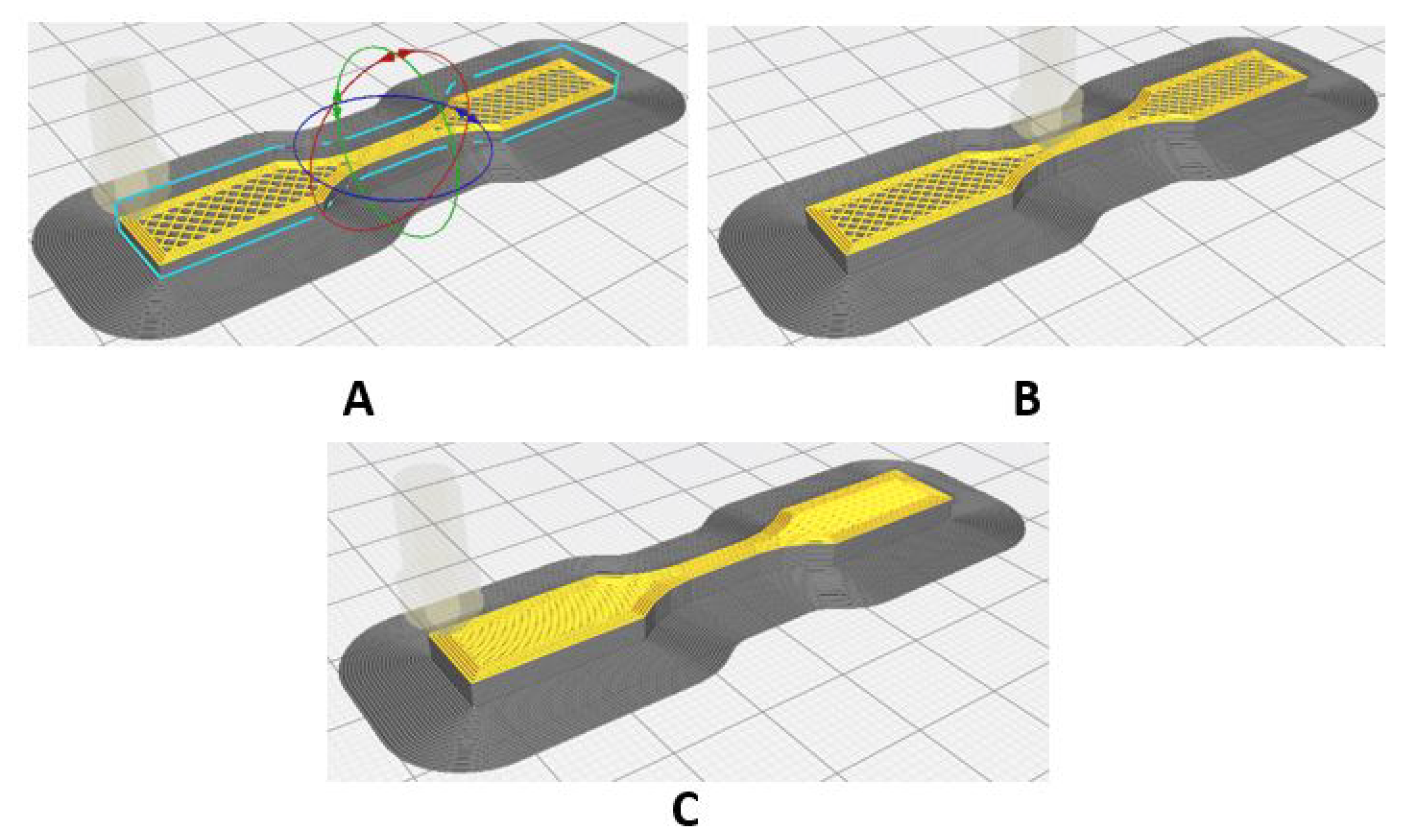
  • Tensile Test Specimen (ASTM D638-14, Type V)[16]: The CAD model of the tensile specimen was based on the Type V design, which is particularly useful when the amount of material is limited. This specimen has an overall length of 63.5 mm, a width of 9.53 mm at the reduced section, and a thickness of 3.18 mm. The dimensions were carefully defined to ensure that the deformation was concentrated in the reduced section, thus ensuring an accurate characterization of the PEEK properties under tension (Figure 3)
Each of the CAD models was designed considering specific dimensional tolerances to ensure the quality of additive manufacturing and the reproducibility of mechanical testing. These models were exported to a stereolithography format for the 3D printer and the generation of the G-code.

2.2. Mechanical Properties of PEEK 450

The material used for the study is PEEK 450 from Apium Additive Technologies, a high-performance semi-crystalline polymer with excellent mechanical, thermal and chemical properties. PEEK is widely used in industrial and medical applications for its ability to withstand extreme conditions. The mechanical properties of natural PEEK 450, specifically in the form of filament roll for additive manufacturing, are highly dependent on the printing process, including factors such as extrusion temperature, layer orientation, and cooling conditions. The mechanical properties of natural PEEK 450 in filament form at 23   ° C are presented in Table 1.

2.3. 3D Printing Parameters

A rectilinear infill pattern of 40 % 70 % 100 % was used in 3D printing, because this type of infill provides a uniform distribution of forces along the structure, and guarantees an internal arrangement that maximizes the rigidity and strength of the specimens. The choice of the rectilinear pattern provides an alignment of the fibres that improves the transmission of the applied loads and avoids stress concentrations that could generate premature failures. It also facilitates the reproducibility of the results, since the observed behaviour is close to that of a solid material. Such a pattern also contributes to reducing the variables in the analysis of mechanical behaviour, ensuring that the results depend mainly on the intrinsic properties of the material and not on the complexity of the internal design.
For manufacturing, an INTAMSYS Funmat PRO 410 was used, a high-performance 3D printer specially designed for printing with specific materials at high temperatures: PEEK, polietercetona cetona (PEKK), polyetherimide (ULTEM) and other advanced polymers. This printer is particularly suitable for industrial and research applications, requiring precise high-strength components. Table 2 summarizes the technical specifications of the equipment.

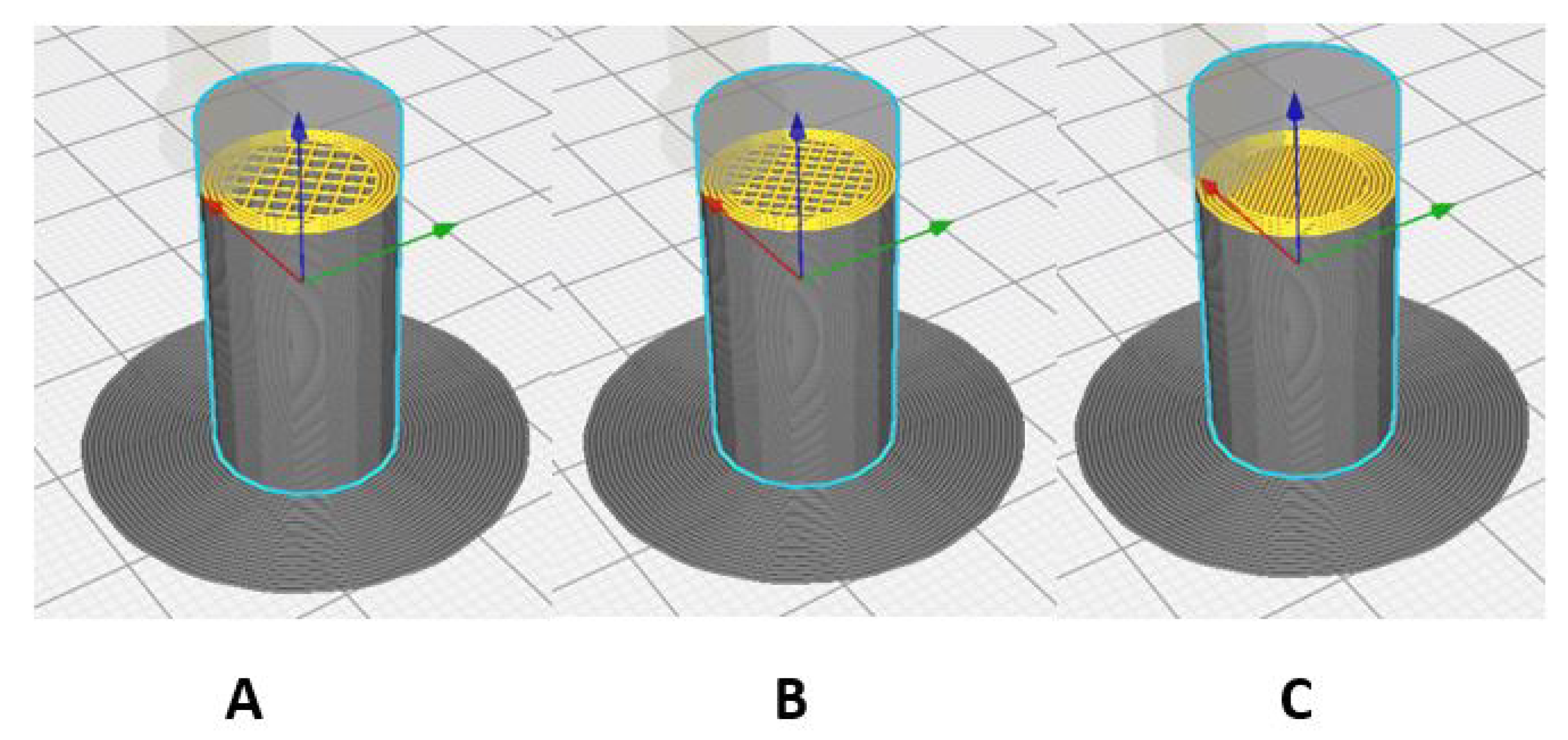
2.4. Fill Pattern in Models

Figure 4 shows the models of the three cylindrical 3D printed specimens, each with a different rectilinear infill pattern, varying from 40 % to 100 % density from left to right. These various levels of infill density will affect strength and stiffness, depending on the specific use for which they are intended.
Figure 5 shows the three V-type specimens, for the tensile test, obtained by 3D printing, each with a different rectilinear filling pattern, varying from 40 % to 100 % filling density, from left to right.
Finally, Figure 6 shows the configuration of the filling density in the specimens for the flexural tests.
This approach seeks to optimize the balance between mechanical strength and weight while ensuring a systematic and controlled comparison of mechanical properties under different densities. A 100 % infill simulates a solid material and offers maximum strength, while lower densities allow for reduced material usage and printing time while maintaining a level of strength suitable for applications where weight is a critical factor. Additionally, the use of the rectilinear pattern ensures a uniform internal structure that helps to distribute loads efficiently, avoiding weak points in the specimens. The selected configuration also seeks to validate the effectiveness of additive manufacturing in the production of high-strength components, since PEEK, being a high-quality material for extreme conditions, must be evaluated in terms of its limitations and advantages when manufactured by FDM 3D printing. These configurations will allow identifying the most suitable biomedical applications for each type of configuration, considering factors such as lightness, strength and functionality of the components produced.

2.5. Environmental Conditions of the Printing Environment

Proper control of the printing environment is essential to ensure the quality and consistency of the manufactured samples. Throughout the printing process of the PEEK specimens, attention was paid to the environmental conditions: temperature and humidity, trying to minimize variations that could affect the properties of the material and, therefore, the results of the mechanical tests.
The printing laboratory, where the INTAMSYS Funmat PRO 410 3D printer was located, was kept at a constant temperature of 22 ± 2   ° C , following best practices reported in the literature. For example, [12] highlights that temperature fluctuations can generate defects in the parts, such as deformations or failures in the layer alignment.
Humidity was also strictly controlled, since PEEK filament, as a hygroscopic material, can absorb moisture from the environment, which could modify its viscosity and alter the mechanical properties of the parts. To avoid these problems, the printing environment was kept at a relative humidity below 40 % . This process is essential to ensure that PEEK remains in its most stable state [13]. This article reports that residual moisture in the filament can cause premature thermal decomposition, negatively affecting strength and other mechanical properties.

2.6. Quality Control

To ensure the consistency and reliability of the results obtained in the mechanical tests, some quality controls were implemented throughout the manufacturing process and analysis of the samples. First, a detailed visual inspection of each printed specimen was carried out to ensure that it did not present visible defects such as cracks, air bubbles or surface imperfections, which could compromise its mechanical properties. Visual inspection is a widely used standard in similar studies [13].
Furthermore, measurements of the dimensions of each sample were made using a digital calliper, verifying that the printed parts met the geometric specifications of the corresponding ASTM standards (D638-14, D695-15, D790-10). This approach follows the recommendation of, for example, [10], which states that accurate measurements of the dimensions of printed parts are crucial for reproducibility of results and effective comparison of experimental data in additive manufacturing.
In order to validate the consistency of the 3D printing manufacturing process, printing parameters such as extrusion temperature, printing speed and layer height were controlled, keeping them within the optimal ranges established by the 3D printing equipment manufacturer. This practice is consistent with the methodology described in [12]. This work concludes that variability in these parameters has a direct impact on the quality of the mechanical properties of the printed PEEK.
Finally, post-processing of the PEEK filament was implemented before printing: the roll of filament was placed in an oven, and subjected to a temperature of 90   ° C for 12 hours, to eliminate any traces of moisture [12,17].

2.7. Setting Up the Experimental Campaign

The experimental campaign begins with 3D printing of natural PEEK 450 specimens following ASTM standards ([18,19]) and ensuring that the samples are uniform and ready for mechanical testing. Once printed, the test pieces underwent a visual inspection and verification of their dimensions, before proceeding with the tests. The Shimadzu machine, equipped with a 20 k N load cell, allows the three types of tests to be carried out: tensile, compression and bending, changing the tooling accessories as necessary.
The tensile test was performed at a speed of 1 m m / m i n for 10 minutes, the compression test at 1.3 m m / m i n for 6 minutes, and the bending test at 1.3 m m / m i n for 8 minutes. These speeds and time intervals allow for obtaining accurate data on the strength and behaviour of the material.
Figure 7 shows the workflow of the experimental campaign to evaluate the mechanical properties of the material.

3. Results and Discussion

3.1. Mechanical Force Behaviour

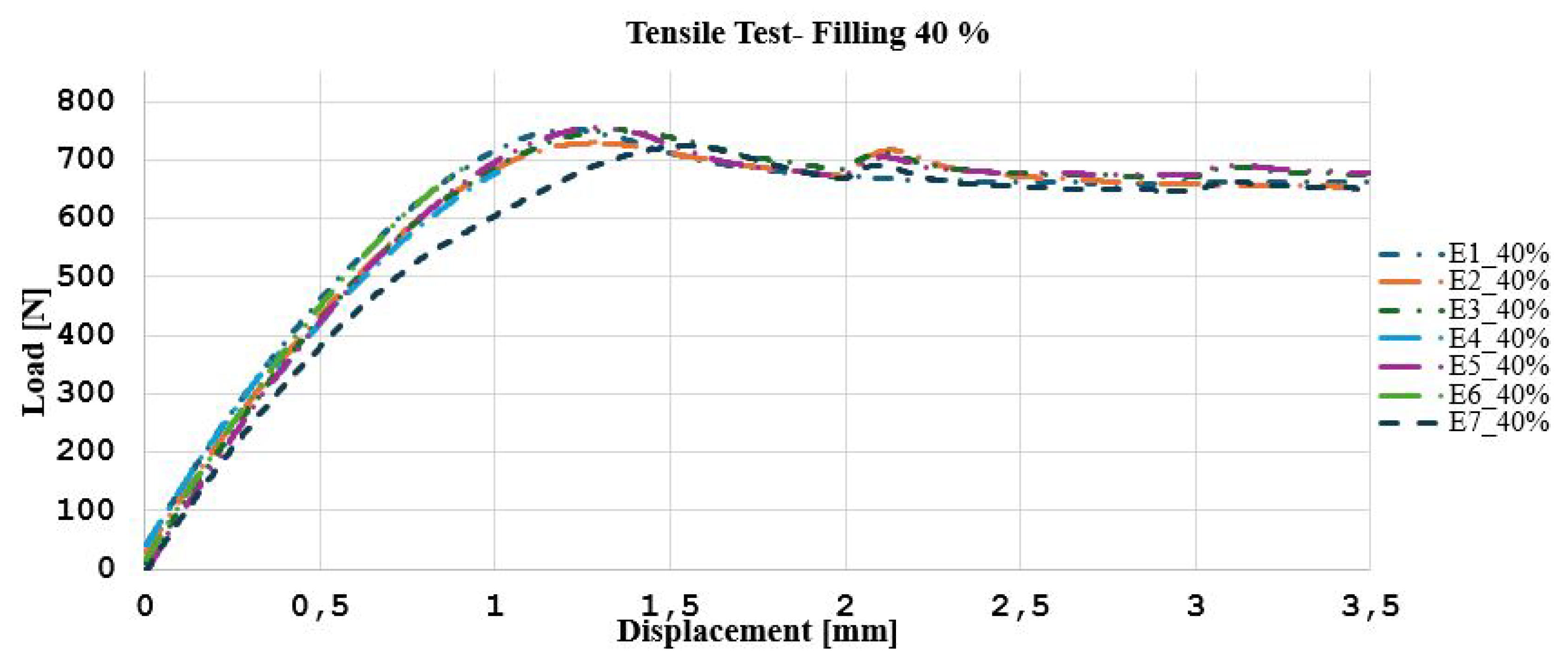
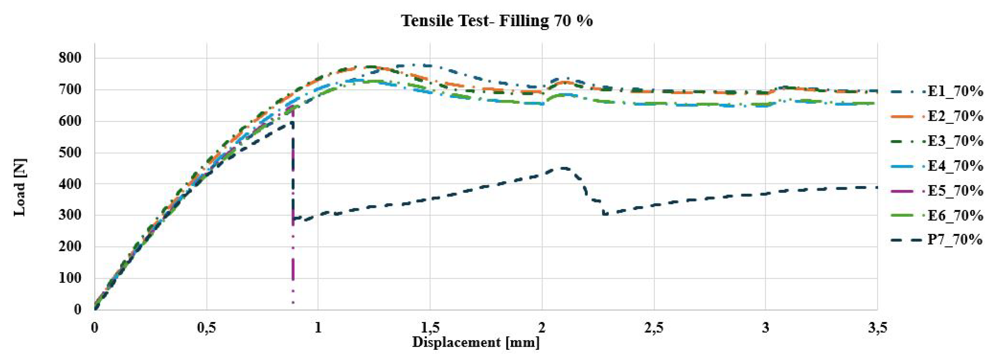
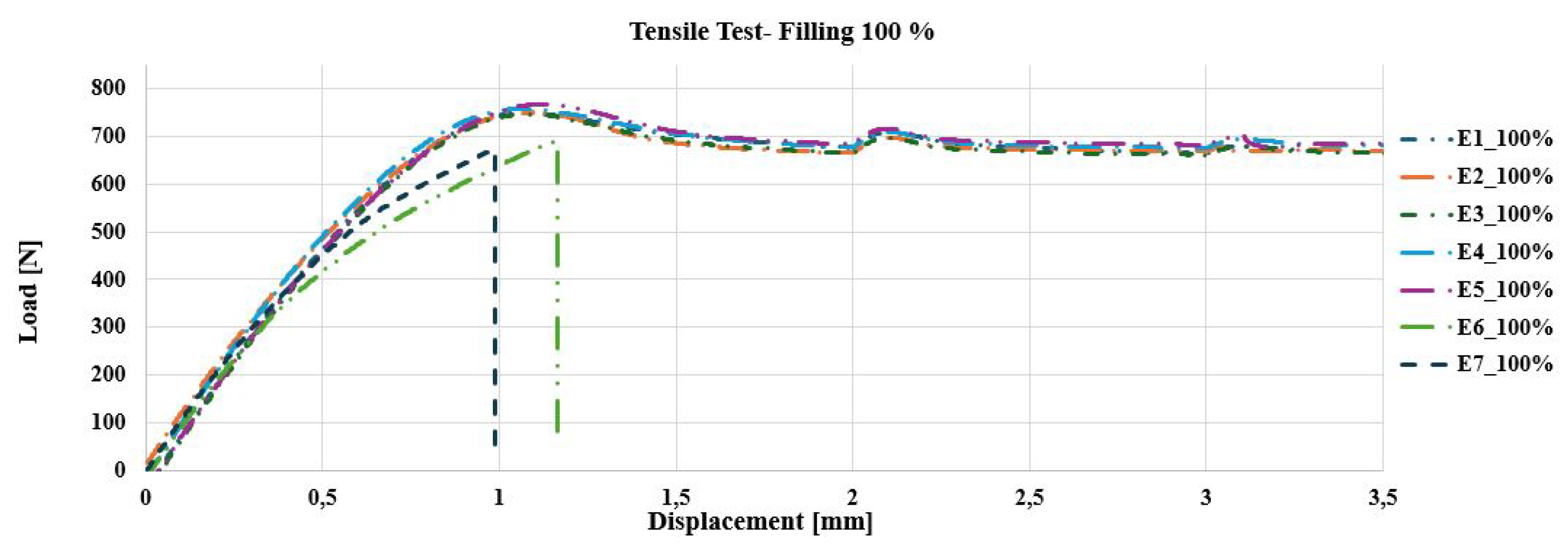
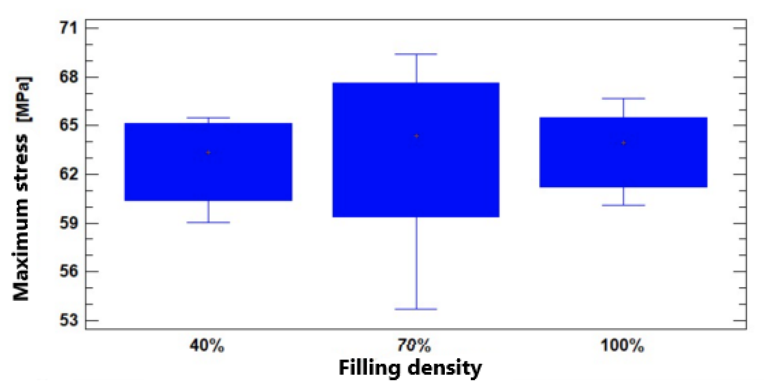
3.1.1. Tensile Analysis

Tensile tests show how the filler density influences the mechanical behaviour. The specimens with 40 % filler reach a maximum load of 700 ± 20 N , showing ductile behaviour. The specimens with 70 % filler support a slightly higher load of 750 ± 25 N . On the other hand, the specimens with 1000 % filler reach a maximum load of 800 ± 30 N . As the filler density increases, the specimens become stronger and stiffer. Figure 8, Figure 9 and Figure 10 show the behaviour of the load-displacement curves for each filler density.
In the case of the experimental tensile campaign, the results were as follows. The specimen with 40 % filler shows a behaviour with a higher elongation ( 4.85 % ), a lower modulus of elasticity ( 2127.04 M P a ), a maximum stress of 63.34 M P a , and a yield stress (yield limit) of 58.87 M P a . These results represent the early failure observed in Figure 11 A, due to the less dense internal structure that generates greater flexibility and lower resistance to the applied load, which allows the specimen to reach its yield limit more easily.
For the 70 % filled specimen, the maximum stress increases to 64.4 M P a , the modulus of elasticity rises to 2294.22 M P a , and the yield stress decreases to 53.71 M P a . These results suggest better internal cohesion and load distribution, resulting in a more uniform failure, with a lower deformation capacity before the collapse, indicative of greater strength without reaching extreme rigidity.
Finally, the 100 % filled specimen presented a maximum stress of 63.95 M P a , a modulus of elasticity of 2436.67 M P a , a reduced elongation of 4.27 % and yield stress of 49.05 M P a , which implies a brittle and rigid behaviour. This is evidenced by the clean fracture observed in Figure 11 A. The high density contributes to a decrease in the energy absorption capacity before failure.
The progressive decrease in yield stress with increasing filler density suggests that the material becomes stiffer and less capable of plastic deformation, which favours brittle failure [7]. The rectilinear filler pattern in the cross-section of the specimens (Figure 11 B) corroborates the influence of the orientation and density of the material on stress transfer and concentration, which translates into significant differences in strength and ductility behaviour [8]. Therefore, as filler density increases, stiffness improves, but deformation capacity and yield stress are reduced, causing higher-density specimens to exhibit more brittle behaviour and less tolerance to elongation before failure[9]. Figure 11 shows the specimens with the damage caused by the tensile test.
Table 3 presents a summary of the average mechanical properties with the three different percentages of fillers, seven samples were tested for each percentage.

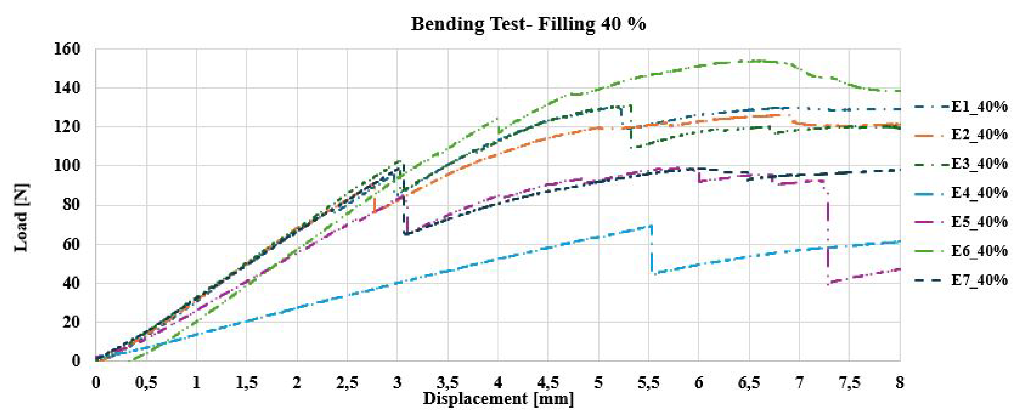
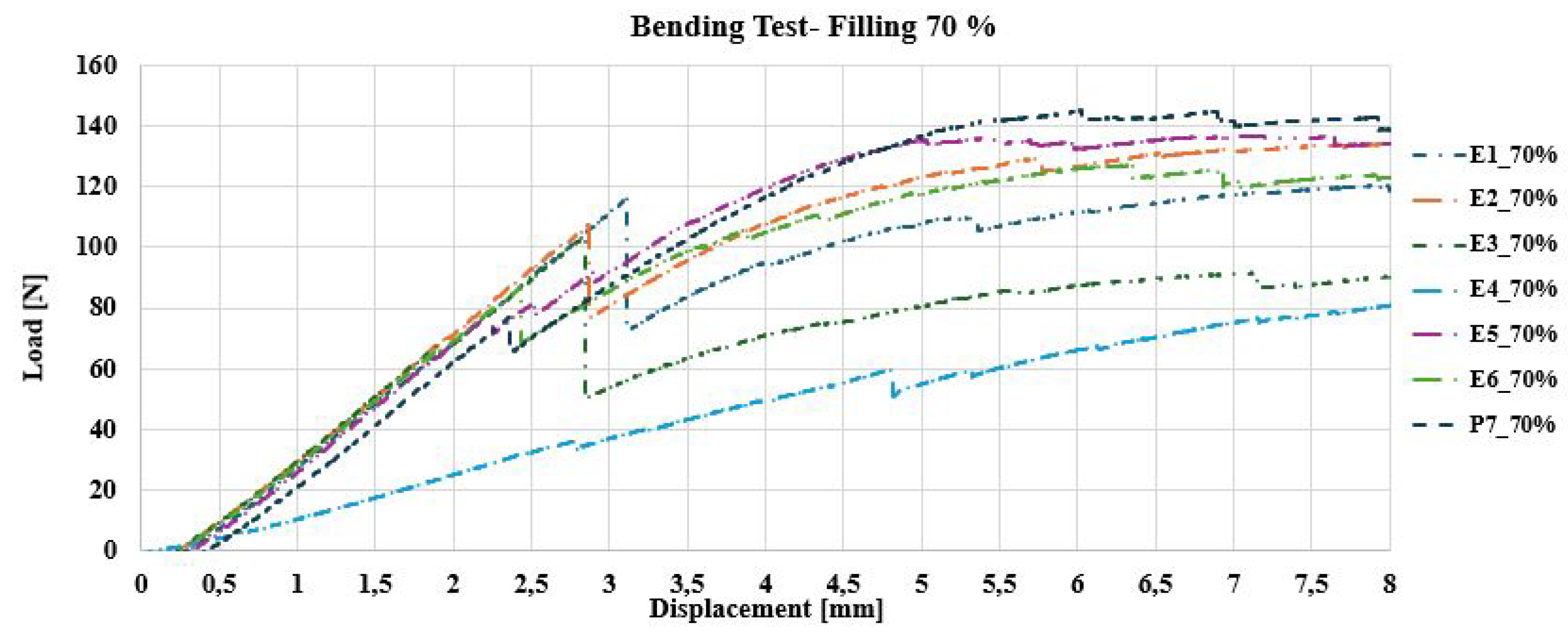
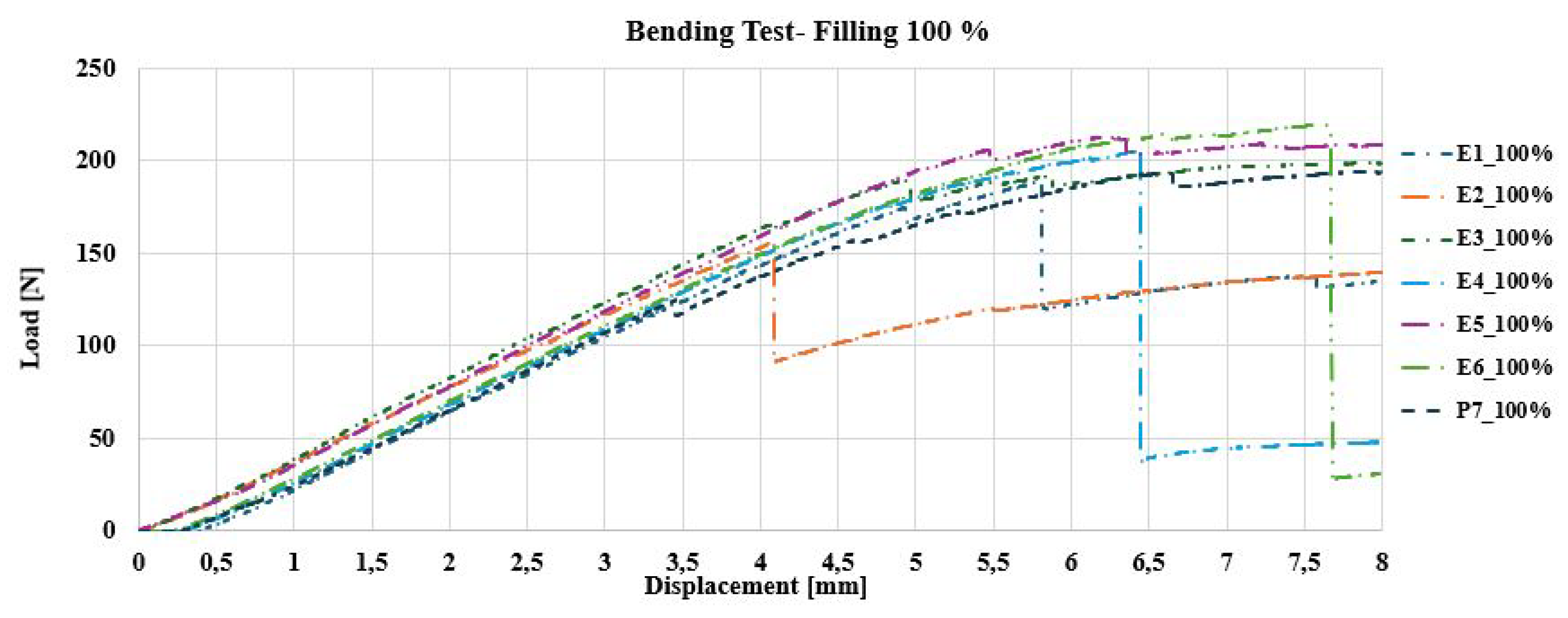
3.1.2. Flexural Analysis

As the density increased from 40 % to 100 % , a significant increase in load capacity and stiffness was observed, indicating an improvement in the strength of the material. The samples with 100 % filler supported an average maximum load of 225.71 ± 11.16 N , the samples with 70 % filler supported 125.71 ± 11.16 N , while the samples with 40 % filler reached 102.86 ± 13.32 N . These results show that a higher percentage of filler not only contributes to greater strength but also a more uniform and consistent response under load. Figure 12, Figure 13 and Figure 14 show the behaviour of the load-displacement curve for each filler density.
Analysis of PEEK specimens under bending load indicates how filler density influences mechanical behaviour and failure. The specimen with 40 % filler deformed considerably, presenting a marked buckling in the middle part due to the lack of material, which made it more flexible but less resistant, with an approximate deformation of 15 % 20 % before breaking. In contrast, the 70 % filled specimen showed an adequate balance between rigidity and flexibility, as it presented a progressive fracture in the centre and a deformation in the range of 10 % 12 % , indicating a better stress distribution and greater resistance, compared to the 40 % filled specimen. Finally, the 100 % filled specimen barely deformed before failing, which demonstrates a very rigid and brittle behaviour, with an abrupt fracture and an estimated deformation of 5 % 8 % [9].
This behaviour suggests that lower-density specimens are more suitable for applications where energy absorption capacity is important, while higher-density specimens are better for applications where structural stability and strength are essential. These results are consistent with previous studies conducted on composite materials and polymers subjected to bending loading [20,21]. Figure 15 shows the bending test results.

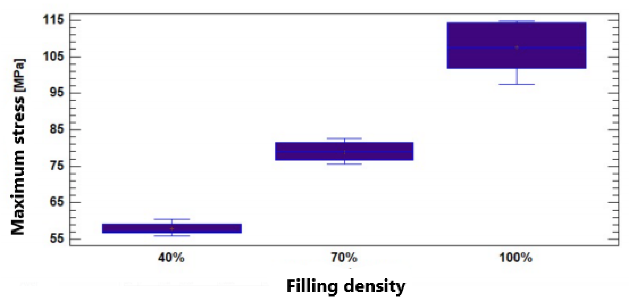
3.1.3. Bending Stresses

The results obtained from the experimental bending campaign on PEEK test pieces with different filler densities demonstrate how, by increasing the filler density (from 40 % to 100 % ), the mechanical properties of the material are significantly altered. The test pieces with 40 % filler reached a maximum stress of 63.43 M P a , with an elasticity modulus of 2134.71 M P a , and an elongation of 5.46 % . These values show that the structure of the material is less rigid, but with a notable capacity to deform before failure, showing ductile behavior that allows energy to be absorbed at the cost of lower resistance.
By increasing the filler density to 70 % , the specimens showed an improvement in flexural strength, reaching a maximum stress of 70.69 M P a , along with an elastic modulus of 2676.21 M P a , and an elongation of 5.54 % . This density represents a good balance between rigidity and flexibility, which improves the material’s ability to adapt to the applied load without losing strength. When the filler density reaches 100 % , a significant increase in structural strength was observed, reflected in maximum stress of 114.32 M P a , and an elastic modulus of 2773.73 M P a , but with an elongation of 5.46 % , which is similar to that resulting from 40 % filler [7].
This behaviour shows a highly rigid, but also more fragile structure, with an abrupt fracture and minimal deformation before failure due to the high stiffness. Table 4 presents a summary of the average mechanical properties with the three different percentages of fillers. Seven samples were tested for each percentage.

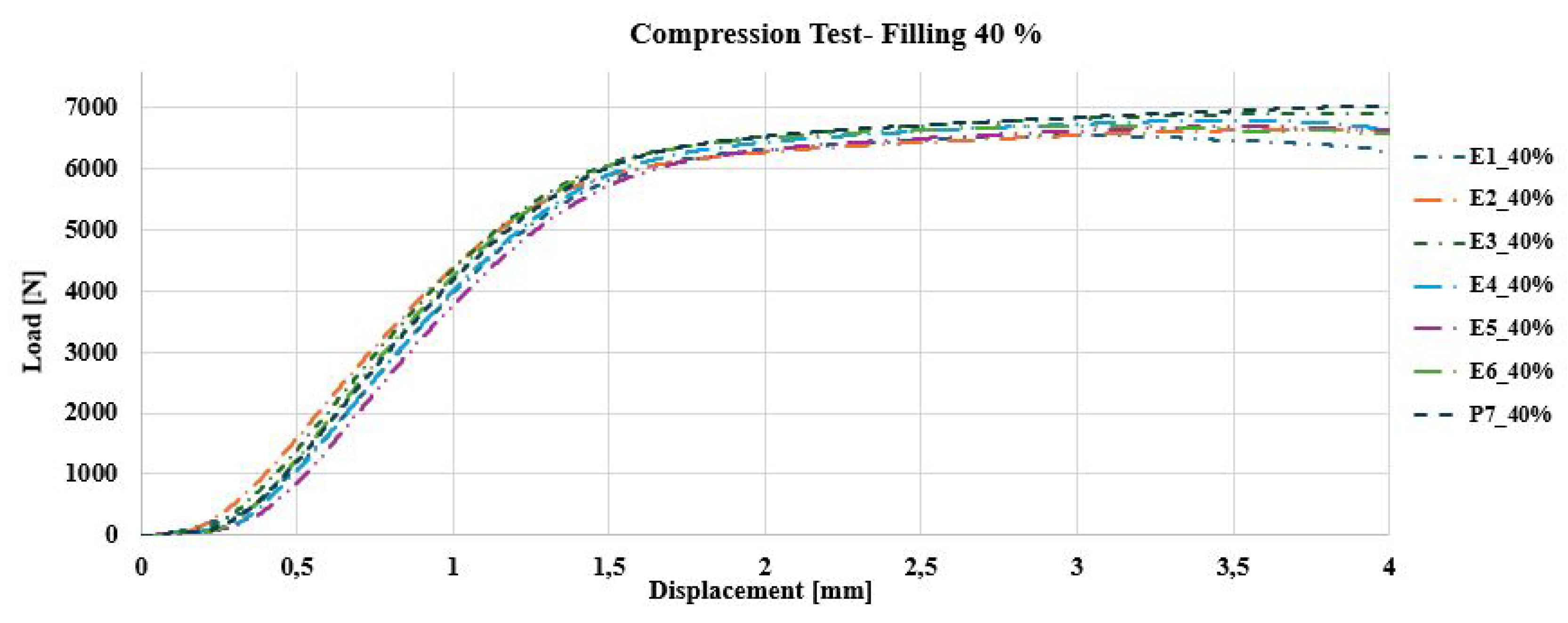
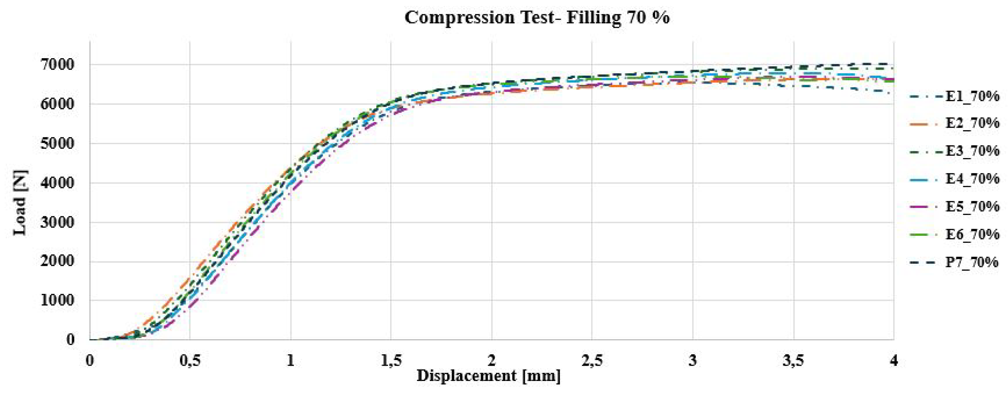
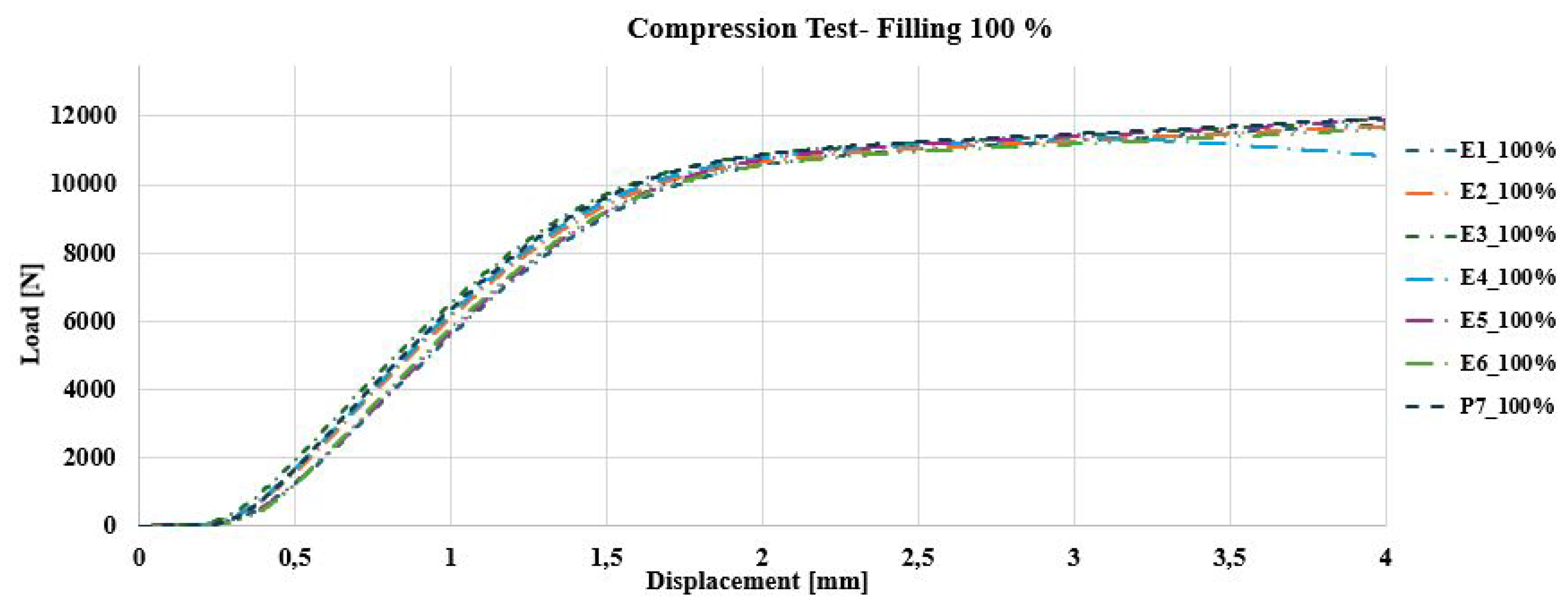
3.1.4. Compression Analysis

The 40 % filled specimens reached an average maximum load of 6500 ± 250 N , which implies a moderate variability. The lower material density causes the specimens to present more internal heterogeneity, reflected in a significant dispersion in the results. With 70 % filled specimens, the average maximum load increased to 7000 ± 200 N , that is, less dispersion than for 40 % filled specimens, showing that a greater amount of material contributes to a better consistency in the mechanical response. Finally, the 100 % filled specimens reached an average maximum load of 11000 ± 150 N , reflecting the greatest uniformity and the lowest dispersion of all.
This completely solid structure allowed the specimens to withstand higher loads with very predictable behaviour. In general, it was shown that as the filling density increases, the compressive strength also increases and the variability in behaviour is reduced, which favours the specimens being more consistent and robust in their mechanical properties.
Figure 16, Figure 17 and Figure 18 show the behaviour of the load-displacement graph for each filling density.
The evaluation of PEEK specimens under compression shows that the filler density has a crucial impact on their behaviour. The specimen with 40 % filler showed significant deformation, with a clear narrowing in the middle part, due to the lower amount of internal material that made it more susceptible to buckling. In comparison, the 70 % filled specimen showed balanced behaviour, with moderate deformation, reflecting a good combination of strength and energy absorption capacity.
Finally, the 100 % filled specimen had the least deformation, maintaining its shape almost intact, indicating high structural rigidity and strength. This differentiated behaviour suggests that, depending on the application, an appropriate filling density can be chosen to balance flexibility and strength. Figure 19 shows the results of the compression tests.

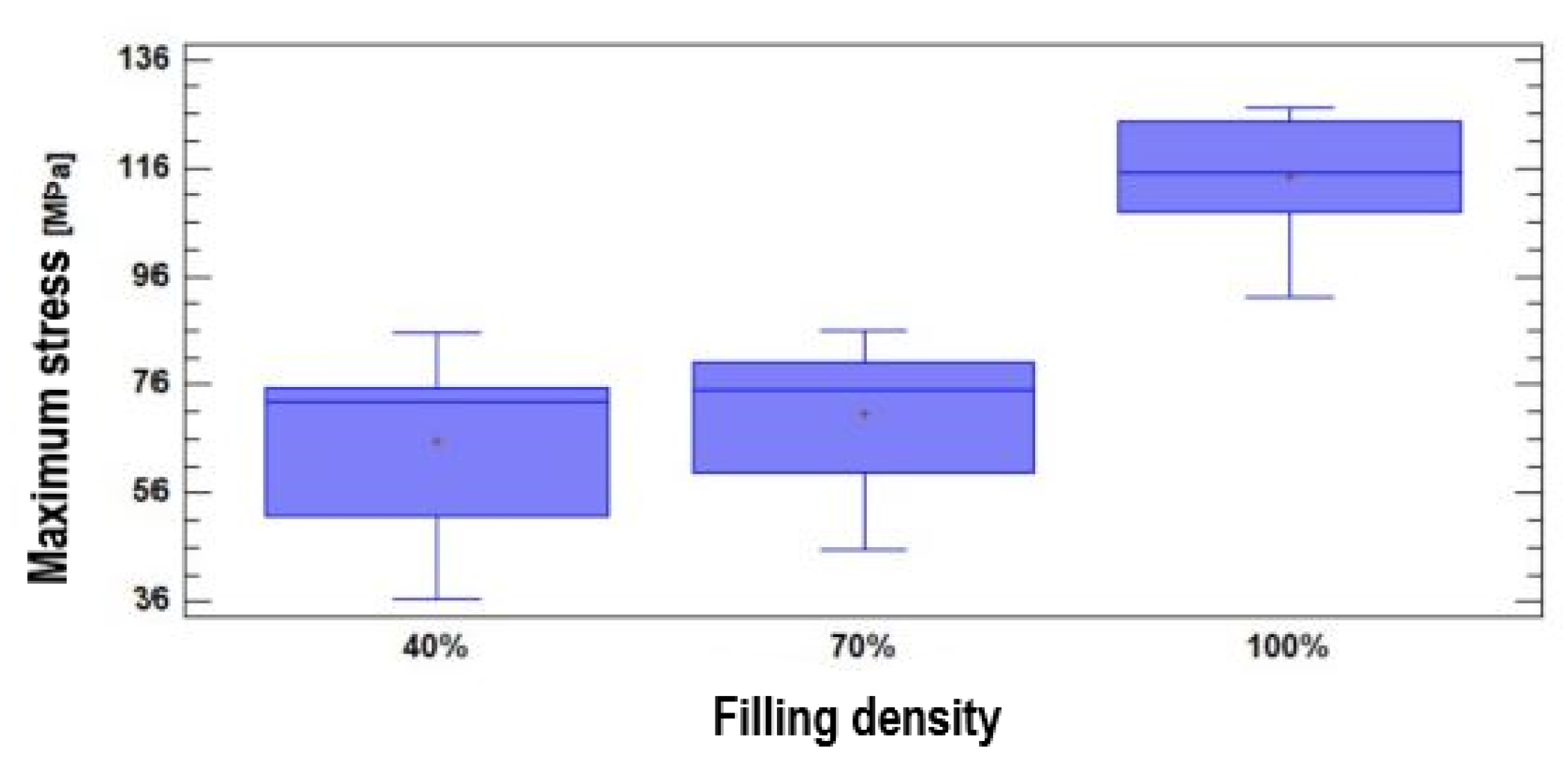
3.1.5. Compressive Stresses

The 40 % filled specimen had the lowest strength, reaching a maximum stress of 58.09 M P a and showing a modulus of elasticity of 149.47 M P a , which makes it more flexible and capable of deforming with an elongation of 15.76 % before failure. This flexibility makes it suitable for applications where energy absorption is more important than strength. The 70 % filled specimen presented a balance between strength and flexibility, withstanding maximum stress of 78.77 M P a with a modulus of elasticity of 162.06 M P a , and an elongation of 20.5 % , which is ideal for applications that require some conformability along with strength.
Finally, the 100 % filled specimen showed the highest strength, with a maximum stress of 107.53 M P a , a modulus of elasticity of 147.47 M P a and an elongation of 20.29 % ; this shows a rigid structure, but still capable of deforming slightly before failing, being ideal for applications that require maximum structural stability.
These results reflect that the higher the filler density, the greater the strength and stiffness, but some of the energy absorption capacity is sacrificed, which makes each density have specific applications depending on the load and deformation requirements. Table 5 presents the summary of the average mechanical properties with the three different filler percentages. Seven specimens were tested for each percentage.

3.2. Statistic Analysis

This section presents the results of applying a one-factor analysis of variance (ANOVA) to the filling density in the printing of the test specimens, measured at three levels: 40 % , 70 % , and 100 % . Furthermore, a 95 % confidence level was considered in analyses for the results of all destructive tests.

3.2.1. ANOVA for the Bending Test

For this test, the analysis of variance showed a null P-value, less than 0.05 . Therefore, there are statistically significant differences in the average maximum stress for the three levels of factor measurement.
The test of Multiple Range showed homogeneity within two groups, and non-homogeneity for the other. While the P-value for the Kruskal-Wallis test was obtained equal to 0.001. Both tests corroborate the incidence of filling density on the observed variable.
In Figure 20, it can be seen that there is no significant variation in the maximum stress for the filling densities of 40 % and 70 % . While for the filling density of 100 % , there is a difference in the result, compared to the other two densities. It means that natural PEEK 450, characterized through additive manufacturing, presents a very similar flexural strength for filler densities of 40 % and 70 % , with values of 65.43 M P a and 70.69 M P a respectively. If the filling density reaches 100 % , then the maximum stress of the material increases to 114.32 M P a . These results show that a higher filling density significantly improves the material’s ability to resist bending stresses, which is relevant for applications requiring high mechanical strength.
[22] reports on an in vitro study of the bending of PEEK for specimens milled from discs, obtaining a bending stress of 250 M P a . Also in [4] a maximum bending stress of 163 M P a is stated for PEEK OPTIMA. In the present investigation, a filling density of 100 % resulted in an average maximum bending stress of 114.32 M P a .

3.2.2. ANOVA for Compression Test

In this case, the analysis of variance showed a null P-value, less than 0.05 . Therefore, there are statistically significant differences in the average maximum stress for the three levels of factor measurement.
The Multiple Range tests showed non-homogeneity within the three groups. The P-value for the Kruskal-Wallis test was obtained equal to 0.000135155 . These two tests corroborate the incidence of filling density on the observed variable. In Figure 21, it can be seen that the maximum stress varies depending on the filling density. Thus, natural PEEK 450 characterized by additive manufacturing has a compressive strength directly proportional to the filler density: 57.79 M P a for 40 % filler, 78.77 M P a for 70 % filler, and 107.53 M P a for 100 % filler. This shows that the increase in filling density results in a significant increase in the material’s resistance to compressive stresses.
In [6], the use of PEEK structures for implant-supported CAD-CAM prostheses is discussed. In this source, the maximum compressive stress of the implantable PEEK-OPTIMA is reported as 135 M P a .

3.2.3. ANOVA for the Tensile Test

The analysis of variance showed a P-value equal to 0.875 , greater than 0.05 . Therefore, there are no statistically significant differences in the average maximum stress for the three levels of factor measurement.
The Multiple Range test also showed homogeneity within the three groups. While the P-value for the Kruskal-Wallis test was obtained equal to 0.261972 . Both tests corroborate the non-incidence of filling density on the observed variable. In Figure 22, it can be seen that the maximum stress does not vary significantly depending on the filling density. That is, the natural PEEK 450 characterized through additive manufacturing presents a very similar tensile strength, with filler densities of 40 % and 100 % , with values of 63.34 M P a and 63.95 M P a respectively. While at 70 % fill the resistance value is somewhat higher (around 64 M P a )
The work [4] presents a classification of the mechanical properties of the PEEK family of polymers, and a comparison with other biomedical polymers, to determine their versatility in applications in medicine. Maximum tensile stress of 100 M P a for medical grade PEEK OPTIMA is reported here, without specifying how the tests were executed. In addition, the author Hernández [5] reports about the performance of tests directly on PEEK dental prostheses, manufactured by injection, and maximum tensile stress of 89.6 M P a was obtained. It is also a very different value than that obtained for natural PEEK 450.
The results obtained in this study on the influence of filler density on the mechanical properties of natural PEEK 450 processed by FDM are in line with trends observed in recent scientific literature. Furthermore, they provide new insights into how to optimize this material for specific applications in the biomedical and industrial fields.
A key finding of this study is the direct relationship between infill density and the mechanical properties of the material. This behavior is consistent with [23], where it is reported that an increase in infill density improves the strength and stiffness of 3D printed materials, but at the expense of lower ductility and energy absorption capacity. In the present study, samples with 100 % infill showed the highest strength and stiffness, making them ideal for structural applications. However, infill densities of 70 % demonstrated a balance between flexibility and strength, making them more suitable for applications where energy absorption is critical.
In [9] the mechanical properties of dental devices fabricated with PEEK using FDM are analyzed, and it is highlighted that higher filling densities are necessary for applications requiring high rigidity, such as dental and maxillofacial implants. The results of this work are consistent with this observation, as the 100 % filled samples showed rigid behavior and high compressive strength.
Stepanov et al., in [24], highlight the importance of combining printing parameters, such as layer orientation and infill density, to improve the mechanical strength of PEEK. Unlike this work, which focuses exclusively on infill density, they also consider multidimensional printing configurations to optimize the material’s performance in biomedical applications. However, like them, the findings reported in this research underline that lower infill densities offer advantages in applications where greater flexibility and lower weight are required.
This research provides new insights by comparing results in terms of specific properties. For example, ANOVA statistical analysis showed significant differences in flexural strength between 70 % and 100 % filler densities, while no relevant differences were found in tensile strength for different densities. That is, filler density has a greater impact on properties that depend on deformation and internal load distribution. This finding extends the conclusions of [1].
In practical applications, the results obtained could guide the design of specific devices, such as:
  • Orthopedic Prosthetics: Configurations with 100 % fill density are ideal for fixation plates requiring rigidity and dimensional stability.
  • Dental implants: Densities of 70 % fill are more appropriate for applications that require a balance between strength and energy absorption, such as maxillofacial prostheses.
  • Lightweight medical devices: Temporary devices, such as surgical guides, can be manufactured with 40 % infill densities, optimizing weight and reducing production times.

4. Conclusions

Specimens for bending, compression, and tensile tests were modelled and printed with natural PEEK 450 through additive manufacturing. The dimensions and structure of the specimens followed industry standards for performing destructive tests on thermoplastic materials. To print the specimens it was necessary to control typical parameters of this process, such as ambient temperature, ambient humidity and printing speed, since they directly influence the quality of the specimens. From the point of view of mechanical properties variation, the controlled variable was the filling density of the specimens.
Bending, tensile and compression tests were developed based on the ASTM D790, ASTM D638, and ASTM D695 standards, obtaining the behaviour of different properties such as maximum stress, modulus of elasticity, yield stress and elongation. And the statistical analysis of the results focused on maximum stress.
The results on maximum stresses obtained in this research, for each type of test, differ from the values reported in the literature consulted. These differences could be related to the fact that the tests in this study were developed following standards for working with thermoplastic polymers and normalized specimens, factors that are not specified in the cited sources.
Natural PEEK 450 is a polymer that is often used in industrial applications [25,26,27]. However, if a bio-compatibilization process is implemented, it could also serve as a raw material for printing personalized medical devices. This would be feasible if the following requirements are met:
  • If a medical device needs to withstand small bending forces, it should be manufactured with a filling density ranging between 40 % and 70 % . A fill density of 100 % is recommended for devices that will undergo significant bending.
  • If the maximum tensile stresses are not required to exceed 64 M P a , then it would be sufficient to manufacture it with a filling density of 40 % .
  • If the medical device is going to be subjected to compression forces, then the maximum load that it must support should be estimated, to establish an appropriate filling density.
The present research could continue in several directions, among which is analyzing the mechanical behaviour of natural PEEK 450 for filler densities different from those considered. Analyze the mechanical behaviour of natural PEEK 450 against impact. Perform destructive testing on medical grade PEEK; but according to current standards, an effective mechanical comparison is possible with the behaviour obtained for industrial grade natural PEEK 450. Perform destructive testing directly on implantable medical devices made of natural PEEK 450.
This study has provided a detailed understanding of how infill density influences the mechanical properties of FDM-processed natural PEEK 450. However, to optimize the design of medical devices and industrial components, future research evaluating additional infill percentages, such as 50 % and 85 % , is essential to identify configurations that balance strength and flexibility. Furthermore, it is important to analyze the impact of different infill patterns on stress distribution and overall mechanical behavior of the printed parts. For example, in [28] it is demonstrated that triangular and cubic infill patterns can improve the stiffness and strength of 3D printed parts. Exploring these patterns in combination with various infill percentages could offer more effective solutions for specific applications.
It is also recommended to investigate how additional printing parameters, such as layer orientation and printing speed, affect the final properties of the material. This line of research will allow the development of better guidelines for additive manufacturing with PEEK, adapted to the particular needs of each application.

Author Contributions

“Conceptualization, Moncayo-Matute F.P. and Vázquez-Silva E.; methodology, Moncayo-Matute F.P., Pintado-Pintado J. A. and Vázquez-Silva E.; software, Pintado-Pintado J. A.; validation, Moncayo-Matute F.P., Torres-Jara P. B. and Pintado-Pintado J. A.; formal analysis, Vázquez-Silva E.; investigation, Pintado-Pintado J. A., Vázquez-Silva E., Moncayo-Matute F.P., Moya-Loaiza D. P.and Torres-Jara P. B.; resources, Moya-Loaiza D. P.; data curation, Moya-Loaiza D. P.; writing—original draft preparation, Vázquez-Silva E.; writing—review and editing, Vázquez-Silva E.; visualization, Vázquez-Silva E.; supervision, Moya-Loaiza D. P. and Torres-Jara P. B.; project administration, Vázquez-Silva E.; funding acquisition, Moya-Loaiza D. P. All authors have read and agreed to the published version of the manuscript.”

Funding

Please add: “This research received no external funding. However, the work was carried out under the auspices of research projects, Development of customized bone implants with reduction of the affected area through the use of surgical guides andadditive manufacturing. Phase I: development of the comprehensive methodology. and Development of customized bone implants with reduction of the affected area through the use of surgical guides and additive manufacturing. Phase II: additive manufacturing with PEEK andP EKK, and evaluation of a superficial modification of the implant, financed by the financed by the Salesian Polytechnic University. Approving resolutions: RESOLUTION No002-003-2020-07-15 and RESOLUTION No005-005-2023-05-25, respectively”.

Informed Consent Statement

“Informed consent was obtained from all subjects involved in the study.” “Written informed consent has been obtained from the patient(s) to publish this paper”

Data Availability Statement

Data included in article/supplementary material/referenced in the article

Acknowledgments

The authors of this work appreciate the support provided by the Research Group on New Materials and Transformation Processes (GIMAT) of the Mechanical Engineering Carrier, in terms of the availability of hours to carry out the research processes. The authors also appreciate the support provided by the Neurosurgery Department of “Instituto de lucha contra el Cáncer – SOLCA”, in Cuenca city, which provided its facilities for performing the surgery and patient follow-up. The authors of the article appreciate the support provided by the Faculty of Mechanical Engineering of the Salesiana Polytechnic University, at its headquarters in the city of Cuenca, and its Research Group on New Materials and Transformation Processes (GIMAT), for the development of this research.

Conflicts of Interest

“The authors declare no conflict of interest.”

References

  1. Dua, R.; Rashad, Z.; Spears, J.; Dunn, G.; Maxwell, M. Applications of 3d-printed peek via fused filament fabrication: A systematic review. Polymers 2021, 13, 4046. [Google Scholar] [CrossRef]
  2. Wang, R.; Cheng, K.j.; Advincula, R.C.; Chen, Q. On the thermal processing and mechanical properties of 3D-printed polyether ether ketone. MRS Communications 2019, 9, 1046–1052. [Google Scholar] [CrossRef]
  3. Li, Y.; Lou, Y. Tensile and bending strength improvements in PEEK parts using fused deposition modelling 3D printing considering multi-factor coupling. Polymers 2020, 12, 2497. [Google Scholar] [CrossRef] [PubMed]
  4. Clavería Gracia, J.; Puértolas Rafales, J.A. PEEK: implantes biomédicos. Máster Universitario en Ingeniería Biomédica, 2011. [Google Scholar]
  5. Hernández Bernal, E. Análisis de prótesis dentales de peek fabricadas por inyección. Tesis de Máster Universitario en Diseño y Fabricación Integrada Asistidos por Computador-Màster Universitari en Disseny i Fabricació Integrada Assistits per Computador, 2021. [Google Scholar]
  6. Ortega Martínez, J.; et al. Aplicación de las estructuras de PEEK para la confección de prótesis CAD-CAM implanto-soportadas. Estudio in-vitro. Tesis Doctoral, 2018. [Google Scholar]
  7. Zhao, Y.; Zhao, K.; Li, Y.; Chen, F. Mechanical characterization of biocompatible PEEK by FDM. Journal of Manufacturing Processes 2020, 56, 28–42. [Google Scholar] [CrossRef]
  8. Wang, Y.; Müller, W.D.; Rumjahn, A.; Schmidt, F.; Schwitalla, A.D. Mechanical properties of fused filament fabricated PEEK for biomedical applications depending on additive manufacturing parameters. Journal of the mechanical behavior of biomedical materials 2021, 115, 104250. [Google Scholar] [CrossRef]
  9. Luo, C.; Liu, Y.; Peng, B.; Chen, M.; Liu, Z.; Li, Z.; Kuang, H.; Gong, B.; Li, Z.; Sun, H. PEEK for oral applications: Recent advances in mechanical and adhesive properties. Polymers 2023, 15, 386. [Google Scholar] [CrossRef] [PubMed]
  10. Moby, V.; Dupagne, L.; Fouquet, V.; Attal, J.P.; François, P.; Dursun, E. Mechanical properties of fused deposition modeling of polyetheretherketone (PEEK) and interest for dental restorations: A systematic review. Materials 2022, 15, 6801. [Google Scholar] [CrossRef] [PubMed]
  11. Wang, P.; Zou, B.; Xiao, H.; Ding, S.; Huang, C. Effects of printing parameters of fused deposition modeling on mechanical properties, surface quality, and microstructure of PEEK. Journal of Materials Processing Technology 2019, 271, 62–74. [Google Scholar] [CrossRef]
  12. Wu, W.; Geng, P.; Li, G.; Zhao, D.; Zhang, H.; Zhao, J. Influence of layer thickness and raster angle on the mechanical properties of 3D-printed PEEK and a comparative mechanical study between PEEK and ABS. Materials 2015, 8, 5834–5846. [Google Scholar] [CrossRef] [PubMed]
  13. Liu, G.; Hu, N.; Huang, J.; Tu, Q.; Xu, F. Experimental Investigation on the Mechanical and Dynamic Thermomechanical Properties of Polyether Ether Ketone Based on Fused Deposition Modeling. Polymers 2024, 16, 3007. [Google Scholar] [CrossRef] [PubMed]
  14. Standard, A. Standard test methods for flexural properties of unreinforced and reinforced plastics and electrical insulating materials. ASTM D790. Annual book of ASTM standards 1997. [Google Scholar]
  15. ASTM, D.; et al. Standard test method for compressive properties of rigid plastics. ASTM materials standards 2002. [Google Scholar]
  16. International, A. Standard test method for tensile properties of plastics; ASTM international, 2014. [Google Scholar]
  17. Wang, Z., C. X.C.X.e.a. Effect of moisture content in polyether-ether-ketone (PEEK) filament on 3D printed parts. Discover Applied Sciences 2024, 6. [Google Scholar] [CrossRef]
  18. Herrero, T.V.V. Caracterización de Probetas de Termoplástico Fabricadas Mediante Impresión 3D. PhD thesis, 2018.
  19. Urresta, C. Caracterización De Las Propiedades Mecánicas De Materiales Impresos Mediante La Técnica De Impresión 3d Fused Deposition Modeling (Fdm). Trabajo de grado previo a la obtención del título de ingeniero en mecatrónica, 2020. [Google Scholar]
  20. Ahmad, M.N.; Yahya, A. Effects of 3D printing parameters on mechanical properties of ABS samples. Designs 2023, 7, 136. [Google Scholar] [CrossRef]
  21. Samykano, M.; Selvamani, S.; Kadirgama, K.; Ngui, W.; Kanagaraj, G.; Sudhakar, K. Mechanical property of FDM printed ABS: influence of printing parameters. The International Journal of Advanced Manufacturing Technology 2019, 102, 2779–2796. [Google Scholar] [CrossRef]
  22. Kewalramani, N. Análisis in vitro de la elasticidad y la flexión del peek. PhD thesis, Universidad Complutense de Madrid Madrid, Spain, 2018.
  23. Hassanpour, M.; Narongdej, P.; Alterman, N.; Moghtadernejad, S.; Barjasteh, E. Effects of Post-Processing Parameters on 3D-Printed Dental Appliances: A Review. Polymers 2024, 16, 2795. [Google Scholar] [CrossRef] [PubMed]
  24. Stepanov, D.Y.; Dontsov, Y.V.; Panin, S.V.; Buslovich, D.G.; Alexenko, V.O.; Bochkareva, S.A.; Batranin, A.V.; Kosmachev, P.V. Optimization of 3D Printing Parameters of High Viscosity PEEK/30GF Composites. Polymers 2024, 16, 2601. [Google Scholar] [CrossRef] [PubMed]
  25. Maharana, T.; Sutar, A.K.; Nath, N.; Routaray, A.; Negi, Y.S.; Mohanty, B. Polyetheretherketone (PEEK) membrane for fuel cell applications. Advanced Energy Materials, 2014; 433–464. [Google Scholar]
  26. Tseng, J.W.; Liu, C.Y.; Yen, Y.K.; Belkner, J.; Bremicker, T.; Liu, B.H.; Sun, T.J.; Wang, A.B. Screw extrusion-based additive manufacturing of PEEK. Materials & Design 2018, 140, 209–221. [Google Scholar]
  27. Al Christopher, C.; da Silva, Í.G.; Pangilinan, K.D.; Chen, Q.; Caldona, E.B.; Advincula, R.C. High performance polymers for oil and gas applications. Reactive and Functional Polymers 2021, 162, 104878. [Google Scholar]
  28. Rajkumar, S. Effect of infill pattern and build orientation on mechanical properties of FDM printed parts: An experimental modal analysis approach. arXiv 2022, arXiv:2202.05692 2022. [Google Scholar]
Figure 1. Geometry and dimensions of the specimen for flexural testing.
Preprints 141729 g001
Figure 2. Geometry and dimensions of the specimen for compression testing.
Preprints 141729 g002
Figure 3. Geometry and dimensions of the specimen for tensile testing.
Preprints 141729 g003
Figure 4. Setting the filling density for compression specimens. A - 40 % ; B - 70 % ; C – 100 % .
Preprints 141729 g004
Figure 5. Setting the filling density for tensile specimens. A - 40 % ; B - 70 % ; C – 100 % .
Preprints 141729 g005
Figure 6. Setting the filling density for flexural specimens. A - 40 % ; B - 70 % ; C – 100 % .
Preprints 141729 g006
Figure 7. Equipment setup for the experimental campaign: A- INTAMSYS 3D printer for manufacturing the PEEK test specimens. B- SHIMADZU universal machine for destructive testing. C- Assembly of the test tools: 1- compression, 2- traction, 3- bending.
Preprints 141729 g007
Figure 8. Load [N] – Displacement [ m m ] behaviour: Tensile Test - Specimens with 40 % filling.
Preprints 141729 g008
Figure 9. Load [N] – Displacement [ m m ] behaviour: Tensile Test - Specimens with 70 % filling.
Preprints 141729 g009
Figure 10. Load [N] – Displacement [ m m ] behaviour: Tensile Test - Specimens with 100 % filling.
Preprints 141729 g010
Figure 11. Tensile test specimens: A - Tensile failure of the standardized specimen with filling levels of 40 % , 70 % , and 100 % . B - Cross section of the specimens to visualize the filling density.
Preprints 141729 g011
Figure 12. Load [N] – Displacement [ m m ] behaviour: Flexural Test - Specimens with 40 % filling.
Preprints 141729 g012
Figure 13. Load [N] – Displacement [ m m ] behaviour: Flexural Test - Specimens with 70 % filling.
Preprints 141729 g013
Figure 14. Load [N] – Displacement [ m m ] behaviour: Flexural Test - Specimens with 100 % filling.
Preprints 141729 g014
Figure 15. Flexural test specimens: A - Cross section of the specimens to visualize the filling density. B - Flexural failure of the standardized specimen with filling levels of 40 % , 70 % , and 100 % .
Preprints 141729 g015
Figure 16. Load [N] – Displacement [ m m ] behaviour: Compression Test - Specimens with 40 % filling.
Preprints 141729 g016
Figure 17. Load [N] – Displacement [ m m ] behaviour: Compression Test - Specimens with 70 % filling.
Preprints 141729 g017
Figure 18. Load [N] – Displacement [ m m ] behaviour: Compression Test - Specimens with 100 % filling.
Preprints 141729 g018
Figure 19. Compression test specimens: A - Deformation of specimens with different filling densities ( 40 % , 70 % , and 100 % ) under compression. B - Top view of compressed specimens showing deformation depending on filling density. C - Cross-sectional view of the internal structure of the specimens after compression.
Preprints 141729 g019
Figure 20. Maximum stress values according to filling density for bending testing.
Preprints 141729 g020
Figure 21. Maximum stress values according to filling density for compression testing.
Preprints 141729 g021
Figure 22. Maximum stress values according to filling density for tensile testing.
Preprints 141729 g022
Table 1. Properties of the natural PEEK 450 filament at 23   ° C .
Mechanical properties
Property Amount Normative
Tensile strength 98 M P a ISO 527
Elongation resistance 45 % ISO 527
Young’s modulus 4000 M P A ISO 527
Impact resistance 7 k J m 2 ISO 179-1eU
Thermal properties
Melting temperature 343   ° C DIN 53765
Glass transition temperature 143   ° C DIN 53765
Decomposition temperature 550   ° C
1 The properties of PEEK were taken from https://apiumtec.com/download/apium-peek-450-datasheet.
Table 2. Technical specifications of the INTAMSYS Funmat PRO 410 Printer and Software used.
3D Print
Print volume 305 × 305 × 406 m m
Connectivity WiFi, Internet, USB
Layer height 50 μ m
X-Y-Z Resolution 0.0016 m m
Filament diameter 175 m m
Nozzle diameter 0.2 , 0.4 , 0.6 , 0.8 m m
Software
Files .stl, .obj
Software INTAMSUITE, simplify3D, Cura
OS Windows
Temperature
Camera 90   ° C
Build plate 160   ° C
Extruder 500   ° C
Table 3. Average maximum stresses in tensile tests.
Specimen Filling density Maximum stress Elasticity Modulus Yield stress
[%] [ M P a ] [ M P a ] [ M P a ]
1-7 40 63.34 2127.04 58.87
8-14 70 64.4 2294.22 53.71
15-21 100 63.95 2436.67 49.05
Table 4. Average maximum stresses in bending tests.
Specimen Filling density Maximum stress Elasticity Modulus
[%] [ M P a ] [ M P a ]
1-7 40 63.43 2134.71
8-14 70 70.69 2676.21
15-21 100 114.32 2773.73
Table 5. Average maximum stresses in compression tests.
Specimen Filling density Maximum stress Elasticity Modulus
[%] [ M P a ] [ M P a ]
1-7 40 58.09 149.47
8-14 70 78.77 162.06
15-21 100 107.53 147.47
Disclaimer/Publisher’s Note: The statements, opinions and data contained in all publications are solely those of the individual author(s) and contributor(s) and not of MDPI and/or the editor(s). MDPI and/or the editor(s) disclaim responsibility for any injury to people or property resulting from any ideas, methods, instructions or products referred to in the content.
Copyright: This open access article is published under a Creative Commons CC BY 4.0 license, which permit the free download, distribution, and reuse, provided that the author and preprint are cited in any reuse.
Prerpints.org logo

Preprints.org is a free preprint server supported by MDPI in Basel, Switzerland.

Subscribe

Disclaimer

Terms of Use

Privacy Policy

Privacy Settings

© 2026 MDPI (Basel, Switzerland) unless otherwise stated