Submitted:
01 December 2024
Posted:
02 December 2024
You are already at the latest version
Abstract
(1) Background: femoral neck fractures are rare but serious injuries in children and adolescents, often resulting from high-energy trauma and prone to complications like avascular necrosis (AVN) and nonunion. Even rarer is the development of slipped capital femoral epiphysis (SCFE) following femoral neck fracture, which presents unique diagnostic and treatment challenges. SCFE can destabilize the femoral head, with severe cases requiring complex surgical interventions; (2) Methods: this report details a case of a 15-year-old male with autism spectrum disorder (ASD) who developed severe SCFE one month after treatment for a Delbet type III femoral neck fracture. The condition was managed with an Imhäuser intertrochanteric osteotomy (ITO), in-situ fixation (ISF), and osteochondroplasty (OChP), supported by virtual surgical planning (VSP) and 3D-printed patient-specific instruments (PSIs) for precise correction and fixation; (3) Results: the surgery was completed without complications. At six months postoperatively, the patient exhibited a pain-free, mobile hip with radiographic evidence of fracture healing and no signs of AVN. Functional outcomes were favorable despite rehabilitation challenges due to ASD; (4) Conclusions: the Imhäuser ITO, combined with ISF and OChP, effectively addressed severe SCFE after femoral neck fracture, minimizing AVN risk. VSP and PSIs enhanced surgical accuracy and efficiency, demonstrating their value in treating rare and complex pediatric orthopedic conditions.
Keywords:
slipped capital femoral epiphysis
; SCFE
; femoral neck fracture
; Imhäuser intertrochanteric osteotomy
; 3D-printing
; virtual surgical planning
; patient-specific instruments
1. Introduction
Femoral neck fractures in children and adolescents are rare but serious injuries, typically resulting from high-energy trauma and representing less than 1% of all pediatric fractures [1]. These fractures are classified using the Delbet system, which categorizes them based on fracture location: Type I (transepiphyseal), Type II (transcervical), Type III (cervicotrochanteric), and Type IV (intertrochanteric) [2]. Pediatric femoral neck fractures are prone to complications, including avascular necrosis, nonunion, and premature physeal closure, which can affect growth and hip function [2]. Avascular necrosis (AVN) remains the most serious complication of these fractures, in particular in Delbet type II and type III, with incidence rates ranging from 6% in nondisplaced fractures to 35% in displaced fractures, independent of treatment approach [3].
Very rarely femoral neck fractures may be complicated by Slipped Capital Femoral Epiphysis (SCFE) [1]. Spence et al. reported a 3% incidence of SCFE in a large case series of femoral neck fracture with average 2.8 years of follow-up [3]. Similarly to the idiopathic SCFE, post-traumatic SCFE is characterized by a posterior and inferior displacement of the femoral head relative to the femoral neck and it requires careful assessment of hip pain in affected patients using appropriate radiological studies [1].
SCFE classification is traditionally based on several criteria: stability (stable vs. unstable), degree of displacement (mild, moderate, or severe), and duration of symptoms (acute, chronic, or acute-on-chronic). The most relevant aspect is to differentiate a stable SCFE, which allows weight-bearing without severe pain, from an unstable SCFE, which involves significant pain and instability, posing a higher risk for AVN [4]. For isolated SCFE, in-situ fixation, without attempting to reduce the slippage, is the most widely accepted surgical treatment, particularly for mild to moderate chronic cases, which are the most common [5,6]. Open or closed reduction is rarely recommended for acute unstable slippage. Intra-articular and extra-articular osteotomies are used for correcting severe head-neck junction deformities, but their recommendations are still controversial [5]. AVN is the most serious complication, particularly in acute unstable SCFE, and is more frequently reported with intra-articular osteotomies for deformity correction [7]. Although the exact etiology of SCFE is unknown, several risk factors have been identified, including endocrine disorders, obesity, and excessive acetabular and/or femoral neck retroversion [8].
Treating SCFE that occurs following a femoral neck fracture presents additional challenges due to the presence of internal fixation devices and the risks associated with a nearby healing fracture site [9]. Over recent decades, only a few cases have been documented, highlighting the need for further evidence to improve treatment approaches for this complication in pediatric orthopedic trauma [10].
This case report describes the treatment of severe SCFE occurred 1 month after surgery for femoral neck fracture in a 15-years-old boy and it was treated with the Imhäuser intertrochanteric osteotomy (ITO) combined with in-situ fixation (ISF) and osteochondroplasty (OChP), describing how virtual surgical planning (VSP) with 3D-printed patient-specific instruments (PSIs) may be helpful for such rare and complex cases.
2. Materials and Methods
2.1. Case Presentation
A 15-year-old male with Autism Spectrum Disorder (ASD) sustained a skiing injury, resulting in a Delbet type III basicervical femoral neck fracture (Figure 1a). He had a BMI of 18.6 (28th percentile by age and sex) with height 177 cm and weight 55 kg. Treatment involved closed reduction and internal fixation using a Dynamic Hip Screw (DHS) plate and an additional free cannulated screw (Figure 1b). Intraoperative fluoroscopic images showed satisfactory reduction on the anteroposterior plane with a residual 15° retroversion deformity on the lateral plane. The reduction was deemed satisfactory, and at a one-month follow-up, progressive fracture healing was noted (Figure 1c). However, three months later, radiographs revealed worsening slippage (Figure 1d). Although initially overlooked, mild slippage was evident on radiographs taken one month post-injury, with residual pain attributed to the recently healed fracture. As the condition worsened, the patient was referred to a tertiary referral center for pediatric orthopedics for further evaluation.
The patient presented with severe limitations in posture and ambulation. Radiographs revealed severe epiphysiolysis with a radiographic posterior sloping angle of 62° with the fracture healed and the fixation devices intact. The fracture had healed, and the fixation devices were in place. After a team discussion, the decision was made to remove the devices, perform ISF, and carry out an ITO with OChP of the residual bump. VSP and 3D-printed PSIs were also planned.
2.2. Virtual Surgical Planning and Design of 3D Printed Cutting Guide
The first step involved generating a virtual 3D model of the affected bone segments, derived from CT imaging using the hospital’s 3D-printing facility. The procedure and workflow, using Mimics Medical software (Materialise, Leuven, Belgium), have been previously described [11]. A mirrored model of the healthy contralateral hip was used to facilitate the analysis of the deformity (Figure 2a). A plane tangent to the base of the epyphysis was created in order to identify the best position of the screw for ISF. This process determined the precise entry point, direction, and length of the screw (Figure 2b). A 6.5 mm Rondò screw (Citieffe s.r.l., Calderara di Reno, Bologna, Italy) was chosen and its length was also determined.
To ensure precise identification of the final plate position and osteotomy sites, a reverse planning approach was employed. This began with a detailed analysis of the deformity, followed by determining the desired angular and rotational corrections to improve hip range of motion (Figure 3a). The correction was planned in valgus, flexion, and internal rotation of the distal femur. The osteotomy site and the final plate position were then meticulously defined in order to prevent intersecting the holes left by previous hardware (Figure 3b and 3c). We chose to use a 4.5 mm 90° Locking Cannulated Blade Plate (OrthoPaediatrics, Warsaw, IN, USA). Subsequently, maintaining the plate in its position relative to the proximal femur, the femur was reverted to its original deformed state (Figure 3d). This step was crucial for designing PSIs for positioning guide wires and for identifying the osteotomy planes.
Once cutting planes, entry points for the epiphyseal screw, and plate position were defined, the design and fabrication of cutting guides were carried out. The guides were modeled using the CAD software Creo Parametric v7.0 (PTC Inc., Boston, MA, USA) and manufactured using Fused Deposition Modeling (FDM) 3D printing technology.
A first PSI was designed to guide the insertion of three guidewires (Figure 4). The most anterior wire, with a diameter of 3 mm, was designated for positioning the epiphyseal screw for ISF, while the other two parallel guidewires of 1.5 mm were intended to assist in positioning the proximal portion of the plate. Notably, the design of the first guide incorporated an opening in the slot for the epiphyseal screw’s guidewire, enabling the PSI to be easily removed without interfering with the parallel wires.
Subsequently, a second and a third PSIs were developed to facilitate the cutting process and ensure the precise alignment of the plate blade during insertion (Figure 5). According to the surgical technique, after inserting the proximal guidewire for the blade plate, the blade slot must be prepared. To address this, both guides were equipped with a support for the chisel to get the desired rotation of the blade and a slot for the second guidewire, which remains unchanged. The design process started with the guide intended for the most distal cut. This guide included a slot to secure the second guidewire for accurate positioning, a recess to direct the chisel during blade slot preparation, and a raised platform to stabilize the saw for precise cutting. Next, the second guide was designed with the same features, but its saw support was specifically aligned for the more proximal cut.
2.3. Surgical Procedure
The patient was positioned on a radiolucent table with the contralateral hip flexed and abducted. The anatomical landmarks were identified, including the anterior superior iliac spine and greater trochanter, and a dotted line was drawn from the anterior superior iliac spine to the patella to assess rotational alignment on the skin. Prior to the procedure, anteroposterior, lateral and oblique views in internal and external rotation were verified using an image intensifier.
A curvilinear lateral incision that incorporated the previous scar was marked. The previous scar was excised, and the subcutaneous tissue was retracted to expose and open the fascia lata in line with the skin incision. An L-shaped incision was made along the proximal inferior border of the vastus lateralis, facilitating subperiosteal exposure of the proximal femur. The DHS plate was subsequently identified and removed, along with the free screw (Figure 5).
At this point the hip was slightly externally rotated for facilitating the positioning of the first patient-specific template (Figure 6). The three guide wires were inserted, the template removed, and the 6.5 mm cannulated epiphyseal screw easily placed along the 3 mm guidewire. The 3 mm guidewire was then removed.
The second PSI was positioned on the femur, leveraging the distal 1.5 mm guidewire as a reference to accurately identify the distal osteotomy site (Figure 7). A longitudinal line was marked along the anterior part of the diaphysis to assess rotational alignment.
The third PSI was then applied to identify the proximal osteotomy and to achieve the correct angulation of the chisel in the sagittal plane, allowing for the placement of the blade plate at 20° of flexion (Figure 8). The cannulated chisel was inserted along the proximal guide wire, while the PSI was still secured to the femur using the distal 1.5 mm guidewire. Notably, both the second and third PSIs could be utilized to guide the chisel, providing a reliable backup in case of device issues such as breakage or contamination.
Once the chisel was in its final position, the third PSI was carefully removed, and the second PSI was reinserted to verify the positions of the two cuts. The distal cut was then marked using an oscillating saw, but not completed. This step facilitated the internal rotation of the distal fragment along the proximal straight osteotomy.
The third PSI was reapplied, and the proximal femoral cut was completed. Afterward, the femur was internally rotated, the chisel removed, and the blade plate gently inserted, securing it with the proximal locking screw to prevent displacement and cut-out.
Next, the distal cut was then completed with the femur internally rotated, and an anterolateral bony wedge was removed. The thigh was flexed and abducted, securing the distal part of the blade plate to the femoral shaft with a clamp. The correct position and orientation of the osteotomy were verified, and the plate was fixed with screws.
After completing the osteotomy, the proximal femur was shifted anteriorly and laterally, improving visibility and access to the residual bump. Taking advantage of the Watson-Jones anterolateral approach, the anterior edges of the gluteus medius and gluteus minimus were partially detached, and the anterior fat pad was elevated to expose the joint capsule. An anterolateral reverse T-shaped capsulotomy was performed. The residual anterolateral bump was identified through visual inspection and fluoroscopic guidance, and was carefully removed using straight and curved osteotomes, rongeurs, and burs. A final fluoroscopic check confirmed the satisfactory removal of the intra-articular bump (Figure 9).
The joint capsule was then closed, the muscles were reattached, and the skin was sutured.
2.3. Postoperative Protocol
The postoperative rehabilitation protocol included passive and active hip motion in flexion and abduction, avoiding hip rotations for the first six weeks. Sitting, standing, and early ambulation with partial weight-bearing were allowed from the day after surgery and continued for six weeks. No cast or brace was required. From 6 to 12 weeks, full weight-bearing was gradually achieved, and full active range of motion of the hip has been restored; swimming and biking were recommended. From 12 to 24 weeks, muscle strengthening exercises, gait improvement, and progressive return to running and jumping were introduced. Return to sports was allowed six months after surgery.
3. Results
The surgery was performed without any complication. Blood loss was 500 mL, the number of fluoroscopic images was 41 (cumulative dose 72.7 cGy/cm2), the surgical time was 176 minutes. At the last follow-up, 6 months postoperatively, the patient had resumed walking, although with difficulties in following the rehabilitation program due to his autism. The hip is highly mobile and pain-free. Radiographs showed good consolidation with no signs of AVN of the femoral head (Figure 10).
4. Discussion
This case report described a SCFE following a femoral neck fracture in an adolescent. Both events are rare in this age group, and their combined occurrence has been documented in fewer than ten cases in the literature (see Table 1 for details) [9,10,12,13,14,15,16,17]. SCFE may develop up to 15 months post-trauma, and it has been frequently reported in children below 10 years of age [9,10,13,14,17]. Based on Loder and Skopelja’s observation that the average age for SCFE onset is 12.0 years in males and 11.2 years in females, with a trend toward younger ages, we might hypothesize that SCFE could be a complication associated with femoral neck fractures in younger patients [18]. However, the case presented here notably increases the age range at which this complication may arise. In our case, we believe that a slight initial malreduction, leaving the neck in mild retroversion, may have increased stress on an already fragile physis. We do not think excess weight played a role, as the patient was very thin (BMI 18.6, 28th percentile by age and sex), although SCFE in non-obese adolescents has been reported to occur at older ages [19]. Another consideration is the choice of fixation, which avoided crossing the physis with cervical screws. While this is the standard choice for children to prevent femoral neck shortening, many believe that crossing the physis in older children poses minimal risk of shortening and it can improve fixation stability, preventing such complications [20].
In nearly all other cases of SCFE following femoral neck fracture reported in the literature, epiphyseal fixation was performed, occasionally accompanied by closed reduction maneuvers. Additionally, an intertrochanteric valgus osteotomy was carried out in four cases (44%). No cases of open reduction and/or modified Dunn procedures were reported. There is ongoing debate on the best strategy to restore joint alignment in moderate to severe slips [5]. Many authors believe intra-articular osteotomies are more effective because they correct the deformity at its source [21]. However, these procedures are technically challenging and carry a significant risk of AVN [22,23]. In contrast, extra-articular osteotomies are simpler to perform, and have a lower risk of complications such as AVN, as they do not compromise the terminal blood supply to the femoral epiphysis [22,23]. However, they are less effective in correcting the femoral deformity, potentially leaving residual bumps that can reduce hip mobility, cause femoro-acetabular impingement, and lead to early osteoarthritis [22]. In our experience, we have confirmed lower rates of AVN and early complications with extra-articular osteotomies but also less effective deformity correction compared to the modified Dunn procedure [24]. We believe extra-articular osteotomy is preferable in cases like this, where the posterior periosteum of the femoral neck, containing the terminal vessels of the epiphyseal blood supply, has already been partially damaged by the fracture and its fixation. Exposing it to further stress from a modified Dunn procedure could have increased the risk of AVN.
We have previously detailed our extensive experience with the Imhäuser ITO [25]. This procedure corrects the position of the femoral epiphysis and restores joint alignment by adjusting the proximal femur in three planes: valgus, flexion, and external rotation. Our earlier studies have shown satisfactory results, with native hip survival at 20, 30, and nearly 40 years of follow-up, and a low risk of necrosis, chondrolysis, and early total hip replacement. These satisfactory results are consistently supported by numerous studies in literature [23,26,27,28,29,30,31,32,33,34].
The use of virtual surgical planning and PSIs for osteotomies in pediatric orthopedic surgery has demonstrated a significant reduction in surgery time and decreased reliance on intraoperative imaging [35,36,37,38]. The reduced use of fluoroscopic imaging serves as an indirect indicator of the efficiency and precision with which correction and fixation are achieved. This support is especially valuable during the Imhäuser intertrochanteric osteotomy, as both the correction and fixation positioning are counterintuitive [39,40]. Having this technology in-house, using low-cost methods and standard implants, lowers costs while maintaining high surgical safety and precision [41,42].
It has been clearly demonstrated that assessing cam deformity in SCFE surgery is essential to prevent acetabular damage and ensure long-lasting hip function [43]. Some authors have even proposed combining the Imhäuser intertrochanteric osteotomy with a safe hip dislocation to enhance visualization and remodeling of the femoral head [44,45]. However, for the recent fracture, we opted to avoid dislocating the head and instead performed OChP through an anterolateral capsulotomy, acoording to the technique reported by Abdelaziz et al. [46]. We noted that there was no mention of additional treatments for the anterior bump in other cases of SCFE following a femoral neck fracture.
5. Conclusions
The Imhäuser intertrochanteric osteotomy, combined with in-situ fixation and osteochondroplasty, proved to be a reliable surgical option for severe SCFE following a femoral neck fracture. Among the cases reported in the literature, there is still no evidence of major complications, such as avascular necrosis and/or early conversion to total hip replacement. The use of Virtual Surgical planning and 3D-printed surgical guides in the Imhäuser intertrochanteric osteotomy can significantly enhance the accuracy of correction compared to the classic approach. Additionally, the residual intra-articular bump can be safely and effectively removed concurrently through an anterolateral approach.
Author Contributions
Conceptualization, G.T. and G.C.M.; methodology, A.D.; software, G.C.M.; validation, G.A., S.C. and M.M.; formal analysis, G.T. and S.C.; investigation, A.C., M.T., M.V.; resources, G.R.; data curation, A.C.; writing—original draft preparation, M.R., M.V. and M.T.; writing—review and editing, A.D.; visualization, M.T. and M.V.; supervision, O.S.S. and G.R.; project administration, G.T.; funding acquisition, G.T. and G.R. All authors have read and agreed to the published version of the manuscript.
Funding
This research received no external funding.
Institutional Review Board Statement
This study was conducted in accordance with the Declaration of Helsinki and approved by the Ethics Committee of “Comitato Etico di Area VastaEmilia Centro” (CE-AVEC 301/2022/Sper/IOR) on 31st May 2022.
Informed Consent Statement
Written informed consent has been obtained from the patient to publish this paper.
Data Availability Statement
The data presented in this study are available on request from the corresponding author due to the patient’s privacy.
Conflicts of Interest
The authors declare no conflict of interest.
References
- Barreto Rocha, D.F.; Horwitz, D.S.; Sintenie, J.B. Femoral Neck Fractures in Children: Issues, Challenges, and Solutions. J Orthop Trauma 2019, 33 Suppl 8, S27–S32. [CrossRef]
- Dial, B.L.; Lark, R.K. Pediatric Proximal Femur Fractures. J Orthop 2018, 15, 529. [CrossRef]
- Spence, D.; Di Mauro, J.P.; Miller, P.E.; Glotzbecker, M.P.; Hedequist, D.J.; Shore, B.J. Osteonecrosis After Femoral Neck Fractures in Children and Adolescents: Analysis of Risk Factors. J Pediatr Orthop 2016, 36, 111–116. [CrossRef]
- Loder, R.T.; Richards, B.S.; Shapiro, P.S.; Reznick, L.R.; Aronson, D.D. Acute Slipped Capital Femoral Epiphysis: The Importance of Physeal Stability. J Bone Joint Surg Am 1993, 75, 1134–1140. [CrossRef]
- Karagüven, D.; Demir, P.; Yüksel, S.; Ömeroğlu, H. A Delphi Consensus Study on the Treatment of Slipped Capital Femoral Epiphysis: Considerable Consensus in Mild and Moderate Slips and Limited Consensus in Severe Slips. J Child Orthop 2023, 17, 299. [CrossRef]
- Haider, S.; Podeszwa, D.A.; Morris, W.Z. The Etiology and Management of Slipped Capital Femoral Epiphysis. Journal of the Pediatric Orthopaedic Society of North America 2022, 4, 589. [CrossRef]
- Sikora-Klak, J.; Bomar, J.D.; Paik, C.N.; Wenger, D.R.; Upasani, V. Comparison of Surgical Outcomes Between a Triplane Proximal Femoral Osteotomy and the Modified Dunn Procedure for Stable, Moderate to Severe Slipped Capital Femoral Epiphysis. J Pediatr Orthop 2019, 39, 339–346. [CrossRef]
- Monazzam, S.; Krishnamoorthy, V.; Bittersohl, B.; Bomar, J.D.; Hosalkar, H.S. Is the Acetabulum Retroverted in Slipped Capital Femoral Epiphysis? Clin Orthop Relat Res 2013, 471, 2145–2150. [CrossRef]
- Li, H.; Zhao, L.; Huang, L.; Kuo, K.N. Delayed Slipped Capital Femoral Epiphysis After Treatment of Femoral Neck Fracture in Children. Clin Orthop Relat Res 2014, 473, 2712. [CrossRef]
- Chinoy, M.A.; Pal, S.; Khan, M.A. Slipped Capital Femoral Epiphysis after Treatment of Femoral Neck Fracture. Pak J Med Sci 2020, 36, S94–S97. [CrossRef]
- Frizziero, L.; Santi, G.M.; Liverani, A.; Napolitano, F.; Papaleo, P.; Maredi, E.; Di Gennaro, G.L.; Zarantonello, P.; Stallone, S.; Stilli, S.; et al. Computer-Aided Surgical Simulation for Correcting Complex Limb Deformities in Children. Applied Sciences 2020, Vol. 10, Page 5181 2020, 10, 5181. [CrossRef]
- Ogden, J.A.; Gossling, H.R.; Southwick, W.O. Slipped Capital Femoral Epiphysis Following Ipsilateral Femoral Fracture. Clin Orthop Relat Res 1975, 110, 167–170. [CrossRef]
- Manukaran, M.N.; Abdul Hamid, A.K. Slipped Capital Femoral Epiphysis Caused by an Implant--a Case Report. Singapore Med J 1989, 30, 406–407.
- Joseph, B.; Mulpuri, K. Delayed Separation of the Capital Femoral Epiphysis after an Ipsilateral Transcervical Fracture of the Femoral Neck. J Orthop Trauma 2000, 14, 446–448. [CrossRef]
- Gopinathan, N.R.; Chouhan, D.; Akkina, N.; Behera, P. Case Report: Bilateral Femoral Neck Fractures in a Child and a Rare Complication of Slipped Capital Epiphysis after Internal Fixation. Clin Orthop Relat Res 2012, 470, 2941–2945. [CrossRef]
- Jung, S.T.; Park, G.H. Slipped Capital Femoral Epiphysis Following Fracture of the Femoral Neck: A Case Report. J Pediatr Orthop B 2012, 21, 579–582. [CrossRef]
- Elbaseet, H.M.; Mohamed, ;; Abdelzaher, A. )473( COPYRIGHT 2023 © BY THE ARCHIVES OF BONE AND JOINT SURGERY Management of Slipped Capital Femoral Epiphysis (SCFE) on Top of Fixed Fracture Neck of Femur (Case Report). Arch Bone Jt Surg 2023, 11. [CrossRef]
- Loder, R.T.; Skopelja, E.N.; Lee, -H; Mathoulin, C.; Song, K.S.; Yuan, H. The Epidemiology and Demographics of Slipped Capital Femoral Epiphysis. ISRN Orthop 2011, 2011, 486512. [CrossRef]
- Obana, K.K.; Siddiqui, A.A.; Broom, A.M.; Barrett, K.; Andras, L.M.; Millis, M.B.; Goldstein, R.Y. Slipped Capital Femoral Epiphysis in Children without Obesity. Journal of Pediatrics 2020, 218, 192-197.e1. [CrossRef]
- Waters, P.M. Rockwood and Wilkins’ Fractures in Children, 9e 2019.
- Ebert, N.; Rupprecht, M.; Stuecker, R.; Breyer, S.; Stiel, N.; Priemel, M.H.; Spiro, A.S. Outcome of the Modified Dunn Procedure in Severe Chronic or Acute on Chronic Slipped Capital Femoral Epiphysis. J Orthop Surg Res 2019, 14, 1–7. [CrossRef]
- Chau, M.M.; Osborne, L.; Mayfield, L.M.; Jo, C.H.; Morris, W.Z.; Podeszwa, D.A.; Sucato, D.J. Outcomes of the Modified Dunn Procedure Versus Delayed Imhauser Osteotomy for Moderate to Severe Stable Slipped Capital Femoral Epiphysis. J Pediatr Orthop 2024, 44. [CrossRef]
- Sikora-Klak, J.; Bomar, J.D.; Paik, C.N.; Wenger, D.R.; Upasani, V. Comparison of Surgical Outcomes Between a Triplane Proximal Femoral Osteotomy and the Modified Dunn Procedure for Stable, Moderate to Severe Slipped Capital Femoral Epiphysis. J Pediatr Orthop 2019, 39, 339–346. [CrossRef]
- Trisolino, G.; Stilli, S.; Gallone, G.; Santos Leite, P.; Pignatti, G. Comparison between Modified Dunn Procedure and in Situ Fixation for Severe Stable Slipped Capital Femoral Epiphysis: A Retrospective Study of 29 Hips Followed for 2–7 Years. Acta Orthop 2018, 89, 211–216. [CrossRef]
- Trisolino, G.; Pagliazzi, G.; Di Gennaro, G.L.; Stilli, S. Long-Term Results of Combined Epiphysiodesis and Imhauser Intertrochanteric Osteotomy in SCFE: A Retrospective Study on 53 Hips. J Pediatr Orthop 2017, 37, 409–415. [CrossRef]
- Maussen, J.P.; Rozing, P.M.; Obermann, W.R. Intertrochanteric Corrective Osteotomy in Slipped Capital Femoral Epiphysis. A Long-Term Follow-up Study of 26 Patients. Clin Orthop Relat Res 1990, 100–110.
- Schai, P.A.; Exner, G.U.; Hansen, O. Prevention of Secondary Coxarthrosis in Slipped Capital Femoral Epiphysis: A Long-Term Follow-Up Study After Corrective Intertrochanteric Osteotomy. Journal of Pediatric Orthopaedics B 1996, 5.
- Parsch, K.; Zehender, H.; Bühl, T.; Weller, S. Intertrochanteric Corrective Osteotomy for Moderate and Severe Chronic Slipped Capital Femoral Epiphysis. Journal of Pediatric Orthopaedics Part B 1999, 8, 223–230. [CrossRef]
- Kartenbender, K.; Cordier, W.; Katthagen, B.D. Long-Term Follow-up Study after Corrective Imhäuser Osteotomy for Severe Slipped Capital Femoral Epiphysis. J Pediatr Orthop 2000, 20, 749–756. [CrossRef]
- Witbreuk, M.M.E.H.; Bolkenbaas, M.; Mullender, M.G.; Sierevelt, I.N.; Besselaar, P.P. The Results of Downgrading Moderate and Severe Slipped Capital Femoral Epiphysis by an Early Imhauser Femur Osteotomy. J Child Orthop 2009, 3, 405–410. [CrossRef]
- Saisu, T.; Kamegaya, M.; Segawa, Y.; Kakizaki, J.; Takahashi, K. Postoperative Improvement of Femoroacetabular Impingement after Intertrochanteric Flexion Osteotomy for SCFE. Clin Orthop Relat Res 2013, 471, 2183–2191. [CrossRef]
- Bali, N.S.; Harrison, J.O.; Bache, C.E. A Modified Imhäuser Osteotomy: An Assessment of the Addition of an Open Femoral Neck Osteoplasty. Bone Joint J 2014, 96-B, 1119–1123. [CrossRef]
- Erickson, J.B.; Samora, W.P.; Klingele, K.E. Treatment of Chronic, Stable Slipped Capital Femoral Epiphysis via Surgical Hip Dislocation with Combined Osteochondroplasty and Imhauser Osteotomy. J Child Orthop 2017, 11, 284–288. [CrossRef]
- Baraka, M.M.; Hefny, H.M.; Thakeb, M.F.; Fayyad, T.A.; Abdelazim, H.; Hefny, M.H.; Mahran, M.A. Combined Imhauser Osteotomy and Osteochondroplasty in Slipped Capital Femoral Epiphysis through Surgical Hip Dislocation Approach. J Child Orthop 2020, 14, 190–200. [CrossRef]
- Raza, M.; Murphy, D.; Gelfer, Y. The Effect of Three-Dimensional (3D) Printing on Quantitative and Qualitative Outcomes in Paediatric Orthopaedic Osteotomies: A Systematic Review. EFORT Open Rev 2021, 6, 130–138. [CrossRef]
- Zheng, P.; Yao, Q.; Xu, P.; Wang, L. Application of Computer-Aided Design and 3D-Printed Navigation Template in Locking Compression Pediatric Hip PlateΤΜ Placement for Pediatric Hip Disease. Int J Comput Assist Radiol Surg 2017, 12, 865–871. [CrossRef]
- Shi, Q.; Sun, D. Efficacy and Safety of a Novel Personalized Navigation Template in Proximal Femoral Corrective Osteotomy for the Treatment of DDH. J Orthop Surg Res 2020, 15. [CrossRef]
- Trisolino, G.; Depaoli, A.; Menozzi, G.C.; Lerma, L.; Di Gennaro, M.; Quinto, C.; Vivarelli, L.; Dallari, D.; Rocca, G. Virtual Surgical Planning and Patient-Specific Instruments for Correcting Lower Limb Deformities in Pediatric Patients: Preliminary Results from the In-Office 3D Printing Point of Care. J Pers Med 2023, 13, 1664. [CrossRef]
- Cherkasskiy, L.; Caffrey, J.P.; Szewczyk, A.F.; Cory, E.; Bomar, J.D.; Farnsworth, C.L.; Jeffords, M.; Wenger, D.R.; Sah, R.L.; Upasani, V. V Patient-Specific 3D Models Aid Planning for Triplane Proximal Femoral Osteotomy in Slipped Capital Femoral Epiphysis. J Child Orthop 2017, 11, 147–153. [CrossRef]
- Lagerburg, V.; van den Boorn, M.; Vorrink, S.; Amajjar, I.; Witbreuk, M.M.E.H. The Clinical Value of Preoperative 3D Planning and 3D Surgical Guides for Imhäuser Osteotomy in Slipped Capital Femoral Epipysis: A Retrospective Study. 3D Printing in Medicine 2024 10:1 2024, 10, 1–7. [CrossRef]
- Frizziero, L.; Santi, G.M.; Leon-Cardenas, C.; Donnici, G.; Liverani, A.; Papaleo, P.; Napolitano, F.; Pagliari, C.; Di Gennaro, G.L.; Stallone, S.; et al. In-House, Fast FDM Prototyping of a Custom Cutting Guide for a Lower-Risk Pediatric Femoral Osteotomy. Bioengineering (Basel) 2021, 8. [CrossRef]
- Trisolino, G.; Depaoli, A.; Menozzi, G.C.; Lerma, L.; Di Gennaro, M.; Quinto, C.; Vivarelli, L.; Dallari, D.; Rocca, G. Virtual Surgical Planning and Patient-Specific Instruments for Correcting Lower Limb Deformities in Pediatric Patients: Preliminary Results from the In-Office 3D Printing Point of Care. J Pers Med 2023, 13, 1664. [CrossRef]
- Ziebarth, K.; Leunig, M.; Slongo, T.; Kim, Y.-J.; Ganz, R.; Ziebarth, K.; Slongo, T.; Ganz, R.; Leunig, M.; Kim, Y.-J. Slipped Capital Femoral Epiphysis: Relevant Pathophysiological Findings With Open Surgery. Clin Orthop Relat Res 2013, 471, 2156. [CrossRef]
- Rebello, G.; Spencer, S.; Millis, M.B.; Kim, Y.J. Surgical Dislocation in the Management of Pediatric and Adolescent Hip Deformity. Clin Orthop Relat Res 2009, 467, 724–731. [CrossRef]
- Baraka, M.M.; Hefny, H.M.; Thakeb, M.F.; Fayyad, T.A.; Abdelazim, H.; Hefny, M.H.; Mahran, M.A. Combined Imhauser Osteotomy and Osteochondroplasty in Slipped Capital Femoral Epiphysis through Surgical Hip Dislocation Approach. J Child Orthop 2020, 14, 190–200. [CrossRef]
- Abdelaziz, T.H.; Elbeshry, S.S.; Goda, A.H.; Fayyad, T.A.; Aly, A.S.; Mahmoud, S.A. Intertrochanteric Imhäuser Osteotomy Combined with Osteochondroplasty in Treatment of Moderate-Severe Stable Slipped Capital Femoral Epiphysis: A Case Series Study. J Pediatr Orthop B 2020, 29, 283–291. [CrossRef]
- Finnegan, M.A. CORR Insights ® : Delayed Slipped Capital Femoral Epiphysis After Treatment of Femoral Neck Fracture in Children. Clin Orthop Relat Res 2015, 473, 2718–2720. [CrossRef]
Figure 1.
(a) Radiograph after trauma showing a Delbet type III femoral neck fracture; (b) Radiograph after open reduction and internal fixation surgery; (c) Radiograph at one-month follow-up showing signs of mild SCFE; (c) Radiograph at three-months follow-up showing worsening SCFE.
Figure 1.
(a) Radiograph after trauma showing a Delbet type III femoral neck fracture; (b) Radiograph after open reduction and internal fixation surgery; (c) Radiograph at one-month follow-up showing signs of mild SCFE; (c) Radiograph at three-months follow-up showing worsening SCFE.
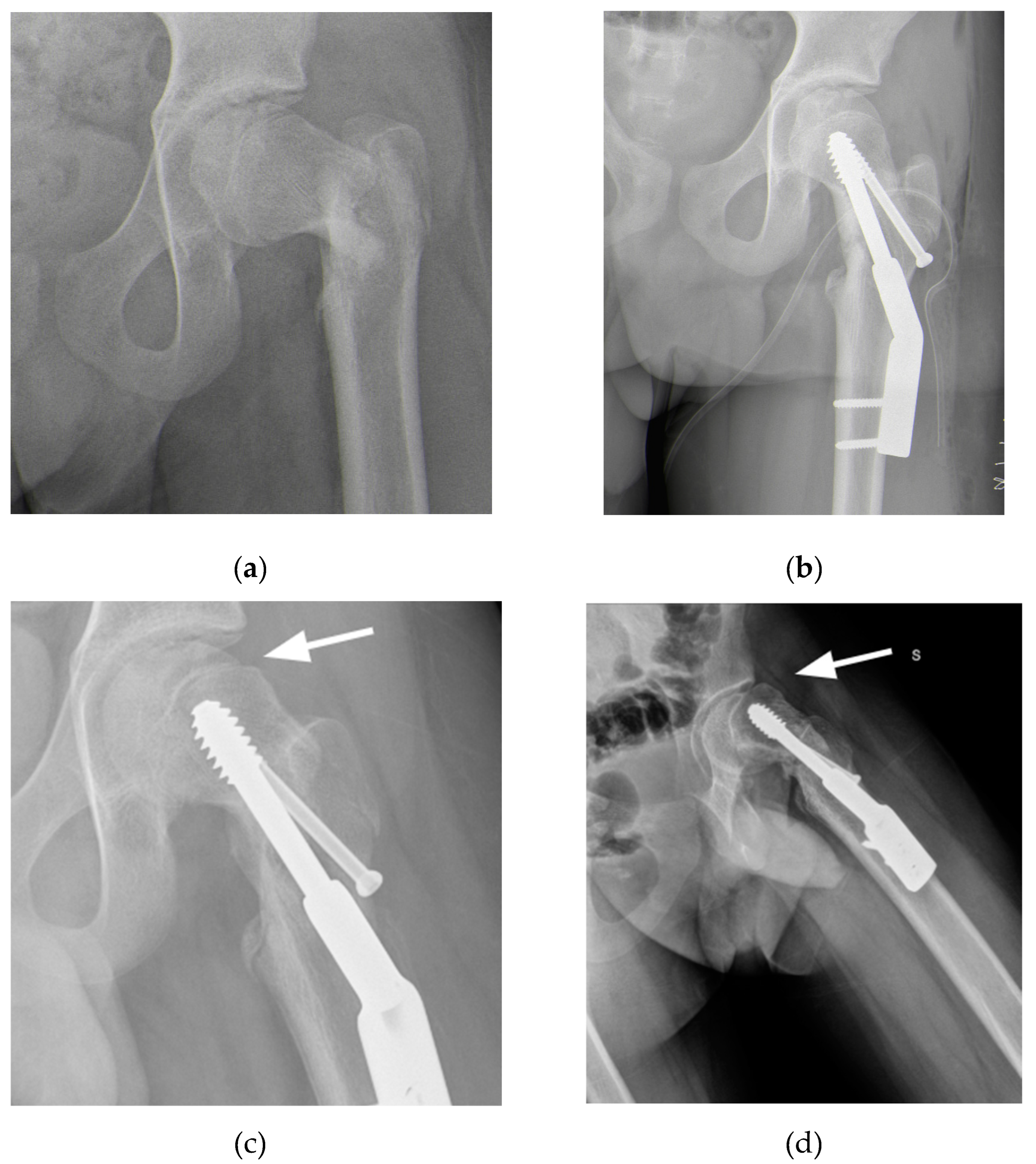
Figure 2.
(a) Overlap of the healthy contralateral femur; (b) Identification of a plane tangent to the base of the slipped epyphysis and of the position of the screw for ISF.
Figure 2.
(a) Overlap of the healthy contralateral femur; (b) Identification of a plane tangent to the base of the slipped epyphysis and of the position of the screw for ISF.
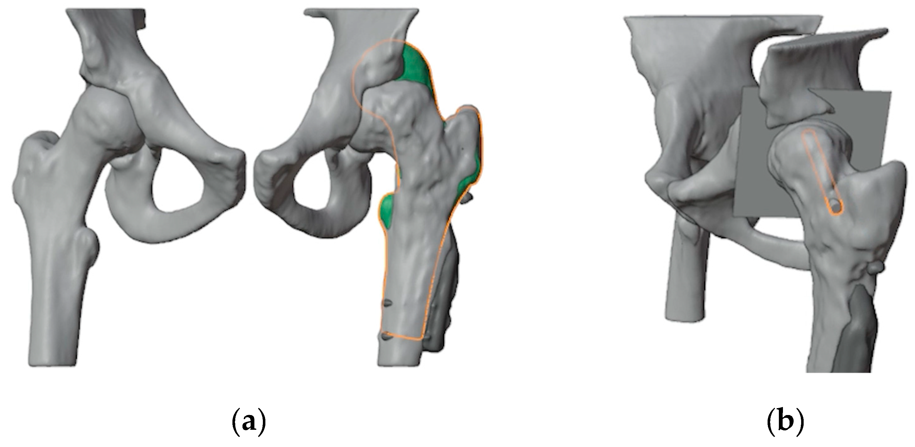
Figure 3.
(a) The first step was to determine the final position of the proximal femur after an intertrochanteric closing-wedge and derotative ostetomy in order to improve the range of motion of the hip; (b) Final positioning of the 90° blade plate; (c) The plate (highlighted in orange) was positioned in order to avoid as much as possible the holes of the previous hardware (in dark gray); (d) Restoring the femur to its deformed state maintaining the plate in its position relvative to the proximal femur reveals the initial position of the blade and the shape of the bone wedge that needs to be removed (in red).
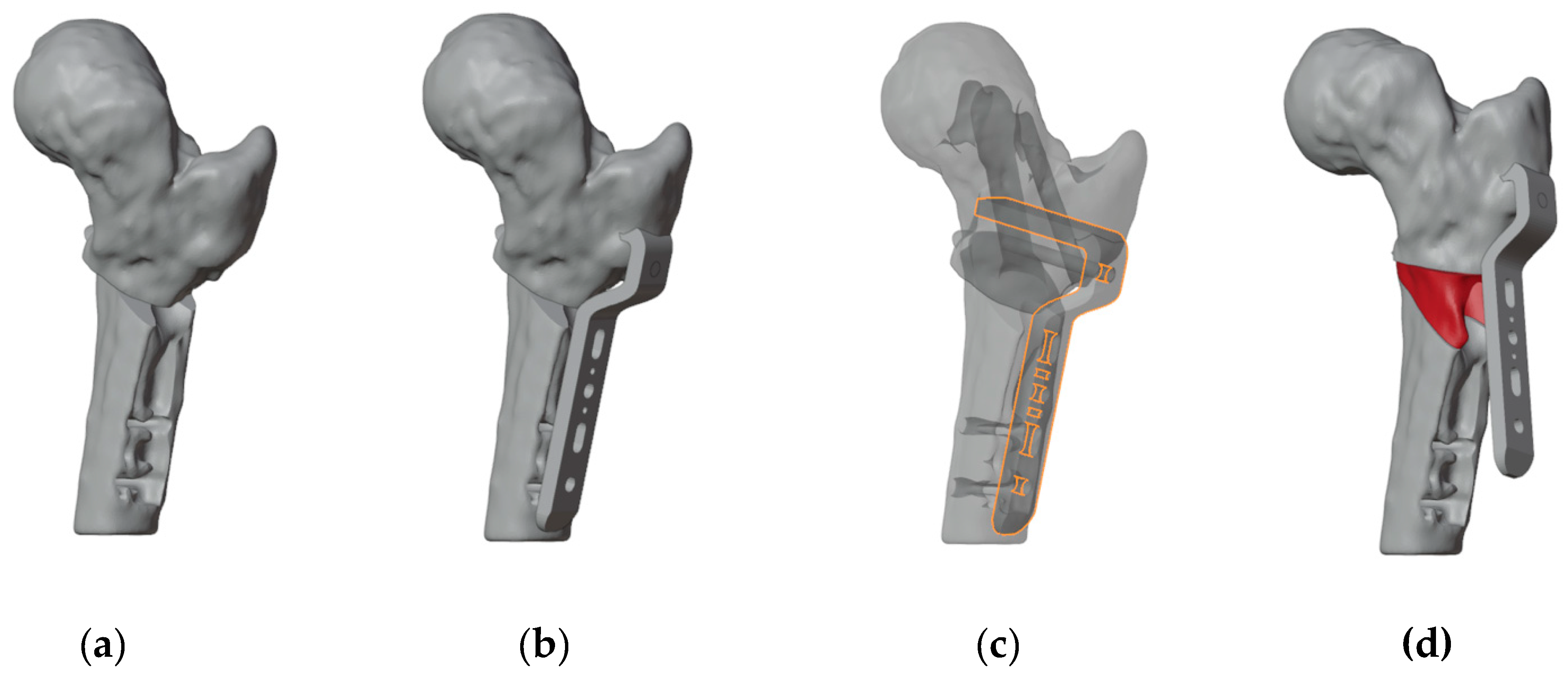
Figure 4.
(a) Anterior view of the proximal femur with the initial plate positioning and the bone wedge to remove; (b) Positioning of the guide wire for the cannulated screw (the more anterior wire) and two lateral wires for the placement of the blade plate; (c) Design of the first 3D-printed PSI.
Figure 4.
(a) Anterior view of the proximal femur with the initial plate positioning and the bone wedge to remove; (b) Positioning of the guide wire for the cannulated screw (the more anterior wire) and two lateral wires for the placement of the blade plate; (c) Design of the first 3D-printed PSI.
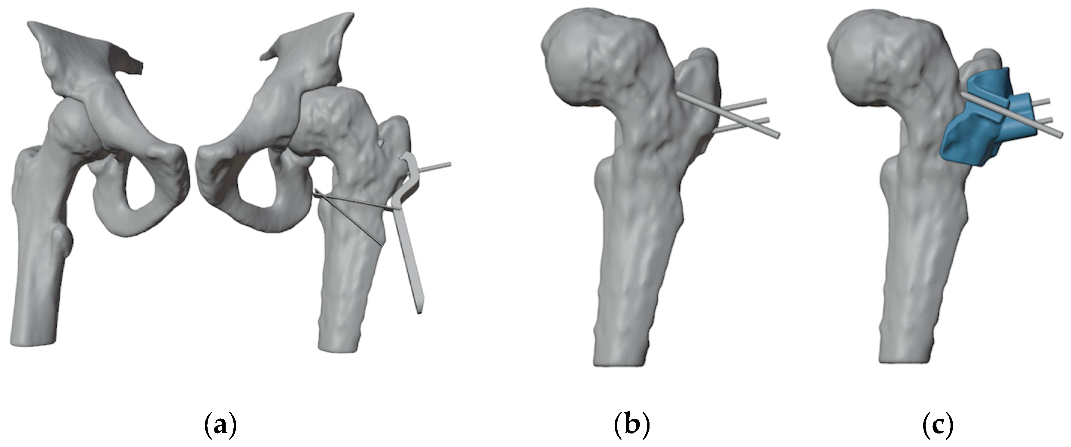
Figure 5.
(a) The position of the chisel along the proximal 1.5 mm guidewire and of the distal 1.5 mm guidewire; (b) The second PSI, designed to fit onto the distal guidewire, precisely indicates the directions for chisel insertion and for the distal cut; (c) Design of the third PSI, featuring similar characteristics to the second, but specifically guiding the proximal cut; (d) Simulated correction in valgus, flexion, and internal rotation of the distal femur.
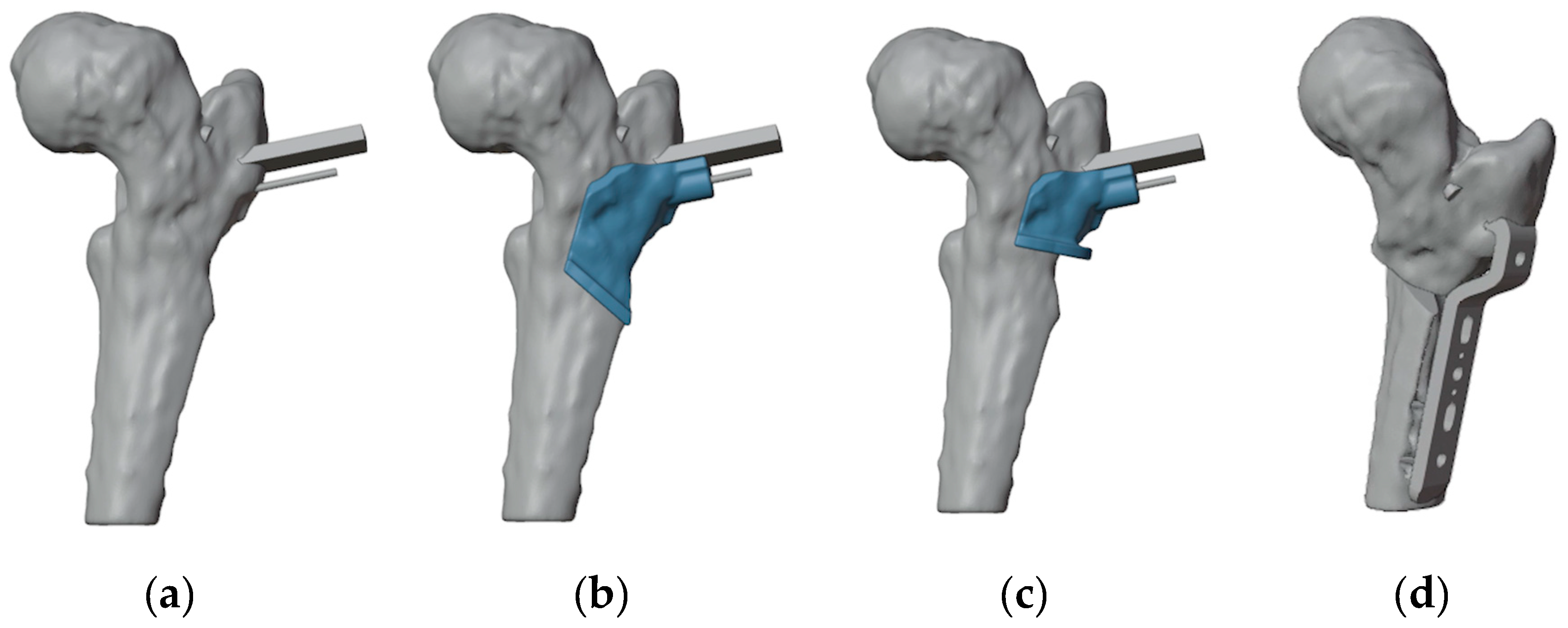
Figure 5.
(a) Anatomical landmark and fluoroscopy check; (b) L-incision along the proximal inferior border of the vastus lateralis; (c) Removal of the DHS plate and of Design of the the proximal anti-rotation screw.
Figure 5.
(a) Anatomical landmark and fluoroscopy check; (b) L-incision along the proximal inferior border of the vastus lateralis; (c) Removal of the DHS plate and of Design of the the proximal anti-rotation screw.
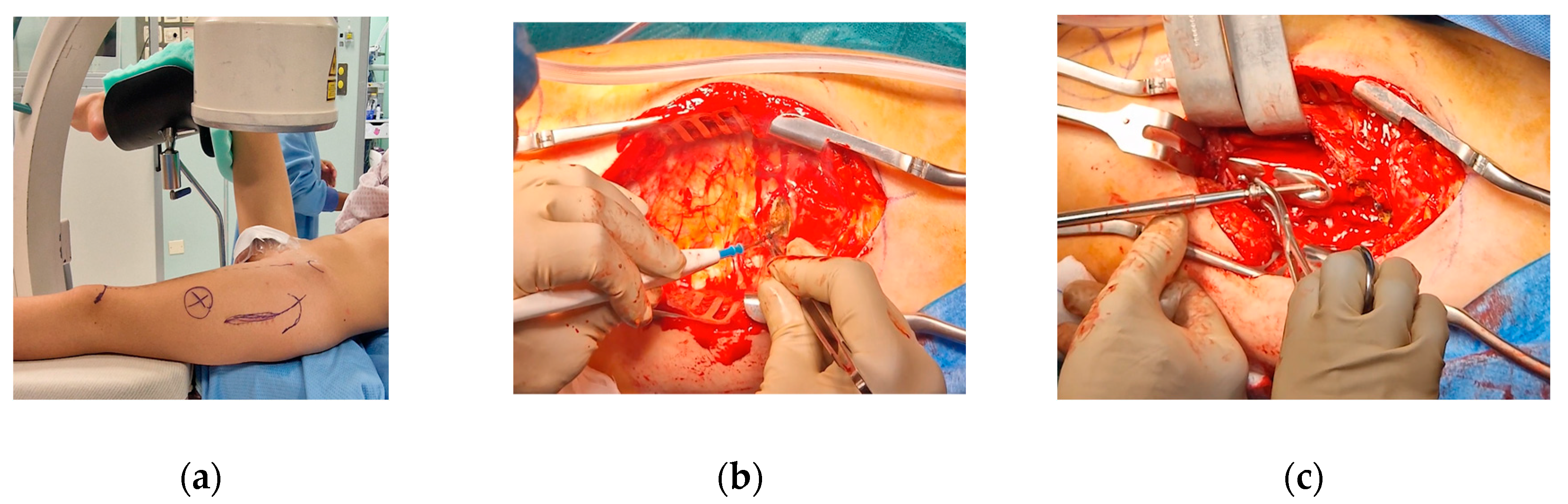
Figure 6.
The intraoperative application of the first PSI. (a) Intraoperative picture of the first PSI in place; (b) Intraoperative imaging of guidewires positioning; (c) Position of guidewires for the free screw for ISF (highlighted in yellow) and for the blade plate (highlighted in orange) in the VSP for comparison with the intraoperative imaging.
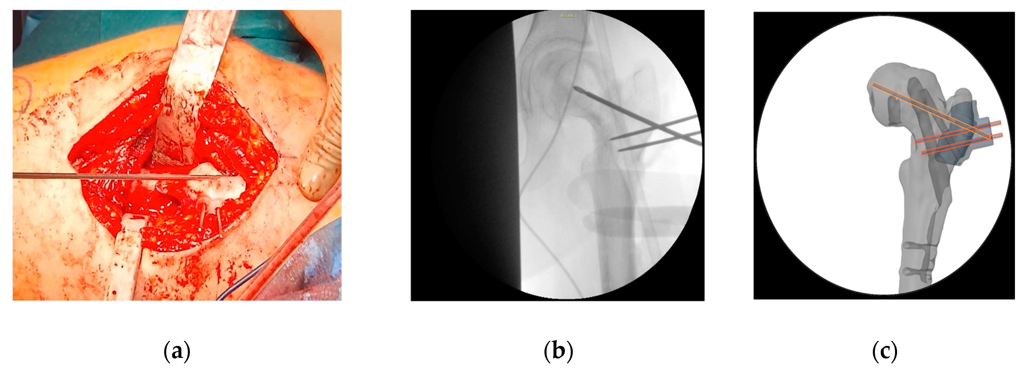
Figure 7.
The intraoperative application of the second PSI. (a) The distal 1.5 mm guidewire was leveraged to precisely fit the second PSI; (b) A longitudinal line was marked to monitor rotational alignment.
Figure 7.
The intraoperative application of the second PSI. (a) The distal 1.5 mm guidewire was leveraged to precisely fit the second PSI; (b) A longitudinal line was marked to monitor rotational alignment.
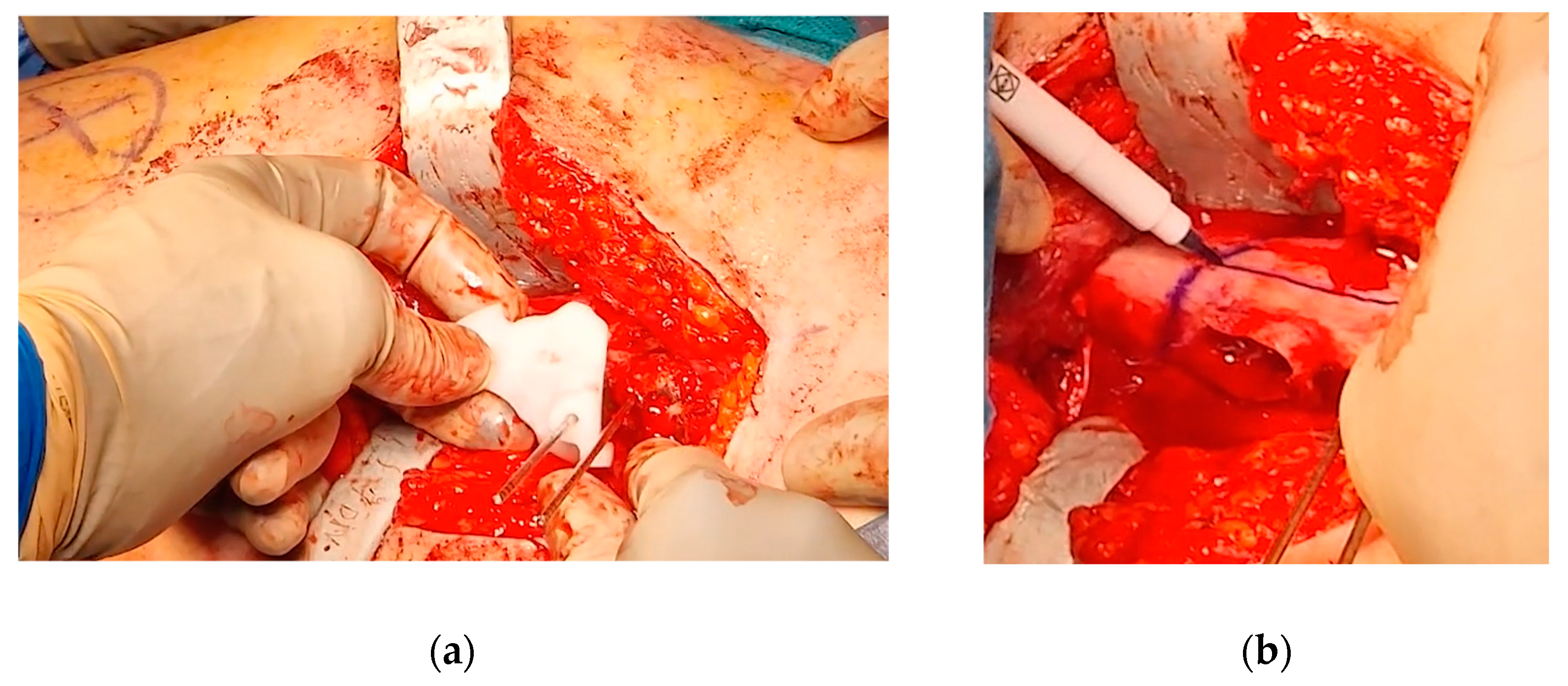
Figure 8.
The intraoperative application of the third PSI. (a) Application of the third cutting guide on the previously inserted guide wire; (b) Application of the third guide to set the correct angulation of the chisel.
Figure 8.
The intraoperative application of the third PSI. (a) Application of the third cutting guide on the previously inserted guide wire; (b) Application of the third guide to set the correct angulation of the chisel.
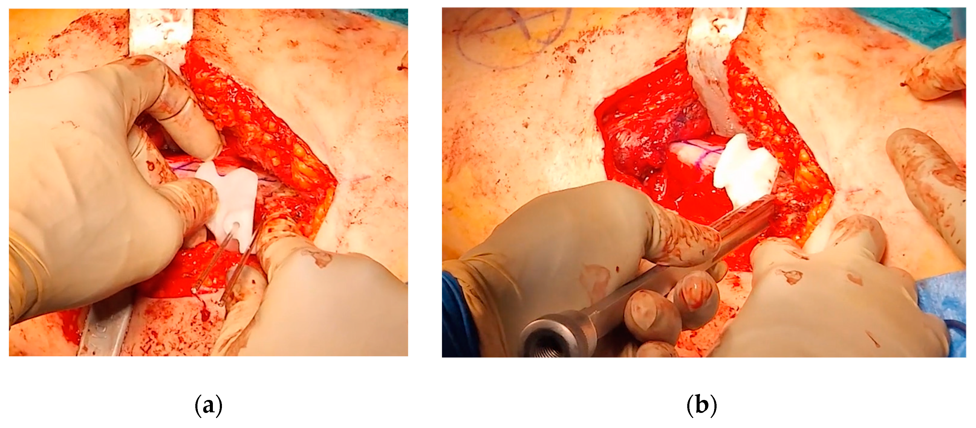
Figure 9.
(a) Intraoperative fluoroscopy showing the anterior bump; (b) Intraoperative fluoroscopy showing the bump removal after the OChP (fine needle marked the area of the resected bump).
Figure 9.
(a) Intraoperative fluoroscopy showing the anterior bump; (b) Intraoperative fluoroscopy showing the bump removal after the OChP (fine needle marked the area of the resected bump).
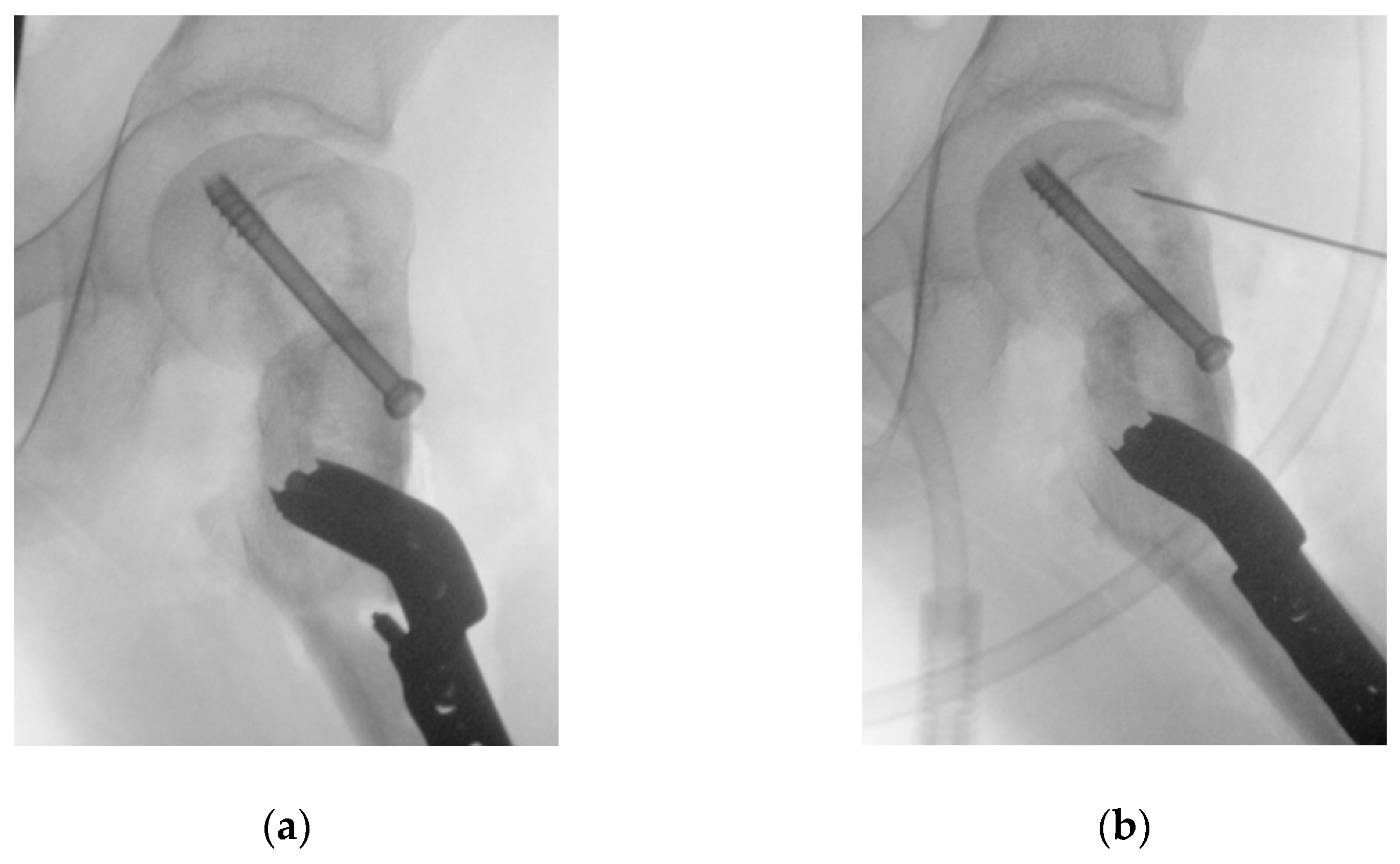
Figure 10.
Radiographs at 6 months follow-up (a) Antero-posterior view; (b) Frog-leg view.
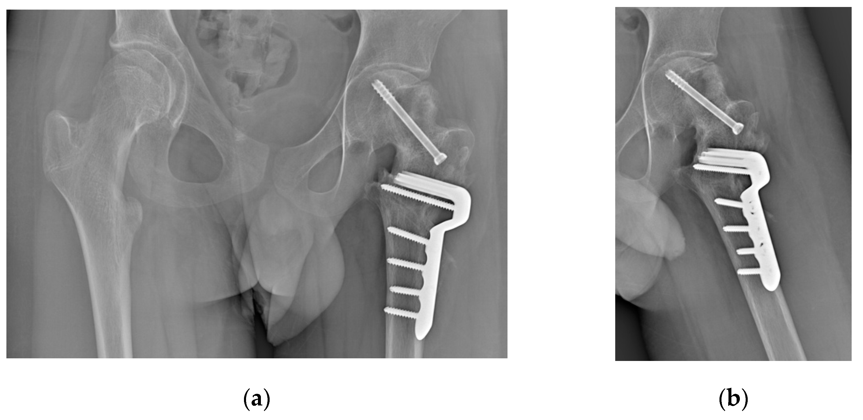

Table 1.
Cases of slipped capital femoral epiphysis (SCFE) after femoral neck fractures described in the literature by year of publication. M = male; F = female; CR = closed reduction; OR = open reduction; ISF = in situ fixation; VO = valgus osteotomy; VFO = valgus and flexion osteotomy; OChP = osteochondroplasty.
| Author and year | Age (years) | Sex | Delbet type | Treatment for fracture | Fracture to SCFE (months) | SCFE severity | Treatment for SCFE |
|---|---|---|---|---|---|---|---|
| Ogden et al., 1975 [12] | 11 | M | II | CR + cast | 15 | Mild | None |
| Manukaran et al., 1989 [13] | 9 | M | III | CR + screws | 14 | Mild | ISF |
| Joseph and Mulpuri, 2000 [14] | 3.8 | M | II | CR + screws | 1 | Moderate | CR + pins + VO |
| Gopinathan et al., 2012 [15] | 10 | M | II | CR + screws + cast | 4 | Mild | CR + screw + cast |
| Jung and Park, 2012 [16] | 11 | M | III | OR + screws + splint | 15 | Mild | ISF + VFO + cast |
| Li et al., 2013 [9] | 12 | F | III | CR + screws + cast | 5 | Moderate | CR + pins |
| Li et al., 2013 [9] | 6 | F | II | CR + plate | 9 | Mild | ISF + VO |
| Chinoy et al., 2020 [10] | 5 | F | III | CR + cast | 7 | Moderate | ISF |
| Elbaseet et al., 2023 [17] | 9 | F | III | OR + screws | 3 | Moderate | ISF + VO |
| Current study, 2024 | 15 | M | III | CR + plate | 1 | Severe | ISF + VFO + OChP |
Disclaimer/Publisher’s Note: The statements, opinions and data contained in all publications are solely those of the individual author(s) and contributor(s) and not of MDPI and/or the editor(s). MDPI and/or the editor(s) disclaim responsibility for any injury to people or property resulting from any ideas, methods, instructions or products referred to in the content. |
© 2024 by the authors. Licensee MDPI, Basel, Switzerland. This article is an open access article distributed under the terms and conditions of the Creative Commons Attribution (CC BY) license (http://creativecommons.org/licenses/by/4.0/).
Copyright: This open access article is published under a Creative Commons CC BY 4.0 license, which permit the free download, distribution, and reuse, provided that the author and preprint are cited in any reuse.


