1. Introduction
Patients after neurological disorders often have to remain in bed for a period due to factors such as unstable physical status, insufficient balancing abilities or weak leg muscles. It has been shown that muscle atrophy and decreased mobility are common challenges faced by patients after prolonged bed rest, particularly in the elderly and critically ill group [
2]. Early activation and mobilisation are essential to prevent these issues, as they play an important role in maintaining muscle mass, improving circulation and accelerating recovery [
3]. Early mobilisation has been shown not only to enhances physical outcomes but also to reduce the length of hospital stay and the incidence of complications [
4]. Early mobilisation involves the process of getting patients to move in bed, sit on the edge of the bed, stand up, and eventually walk [
5]. However, the current approach to early mobilisation often focuses on getting the patients to sit, stand up, etc, which requires manual assistance. Although moving in bed is recommended, in-bed mobilisation is often infeasible or insufficient to be performed on the patients, due to too intensive manual tasks or understaffing of the clinical team [
6]. The gap between the requirement for early mobilisation and the limited training facilities highlights the need for innovative solutions that provide effective in-bed exercise, engaging even the most vulnerable patients in required physical activity.
There are several products on the market to assist training in bed, but the movement pattern needs to be improved. Automatic assistance of the lower limbs is achieved by actuation of the thigh or the foot. A representative example of the system for thigh actuation is Erigo [
7]. It consists of a tilt table with two actuated thigh cuffs and two spring-supported foot plates. Erigo allows patients to practise hip and knee flexion with limb loading on the tilt table. Vemotion [
8], a mechanism which allows easy installation on the individual bed, avoids the task of patient transfer. It also allows hip and knee flexion in a lying position. Another approach to early rehabilitation is the use of in-bed cycling devices. The system bemo (THERA-TRAINER Medika Medizin Technik GmbH, Hochdorf, Germany) is a robotic-assisted over-bed cycling device for early mobilisation. It consists of a frame with an automatic pair of cycling pedals. The height of the pedals and the cadence can be automatically adjusted. The rollers at the bottom make it easy to position the bemo so that the pedals are in the most suitable position for the individual patient who is lying or sitting on the bed. The Motomed Letto (RECK-Technik GmbH, Betzenweiler, Germany) consists of a standing frame, a drive unit and two pedals [
9]. It produces a circular foot trajectory for patients lying on the bed. The in-bed cycling devices allow patients to engage in training without leaving their beds. It is shown that the in-bed cycling is acceptable, safe, and feasible to implement [
10]. However, no significant benefit of early rehabilitation was found [
11]. It has been argued that the training intensity should be tailored to the patient’s physical condition [
12].
Based on the available devices on the market, we want to develop a compact lower-limb therapy device for in-bed usage that produces adjustable leg movement with dynamic loading on the foot. The first functional model was developed to include two foot plates that were actuated by pneumatic cylinders [
13]. The air flowed inside the two cylinders. When one foot plate was pressed by the user, the other foot plate retracted reciprocally. The resistance could be adjusted by valves. Such an unactuated leg press did not require electricity or an air compressor. After assessment by physiotherapists, the lightweight in-bed leg-press was considered to meet the functional requirements for early leg mobilisation. However, the system only reacts to patients’ active pressing on the foot plate. For the weak patients who cannot press voluntarily, the device cannot be used effectively.
In order to improve the system for a large population, a new in-bed lower-limb therapy device is being developed. The first iteration of a user-centred design process for such a device [
6] yielded the following user requirements:
(1) it should be lightweight and compact for transport and storage,
(2) it should be easy to use, not only for clinical staff but also for patients in cases they use it without specialist supervision,
(3) it should provide therapeutic passive and active leg exercise,
(4) it should provide dorsiflexion/plantarflexion, and
(5) it should provide an intuitive user interface with interactive exergames.
The aim of this work was to develop and evaluate an in-bed lower-limb therapy device that provides various training patterns for the foot and leg with an intuitive user interface and interactive exergame.
2. Materials and Methods
The mechanical structure of the lower-limb therapy device was described, then the control strategies, programme architecture and computer game were developed, followed by the description of the system evaluation test on 12 able-bodied participants.
2.1. Mechanical Development
The lower-limb therapy device was designed in NX (NX2312, Siemens Switzerland Ltd., Zurich, Switzerland) and embodied in a prototype (
Figure 1 and
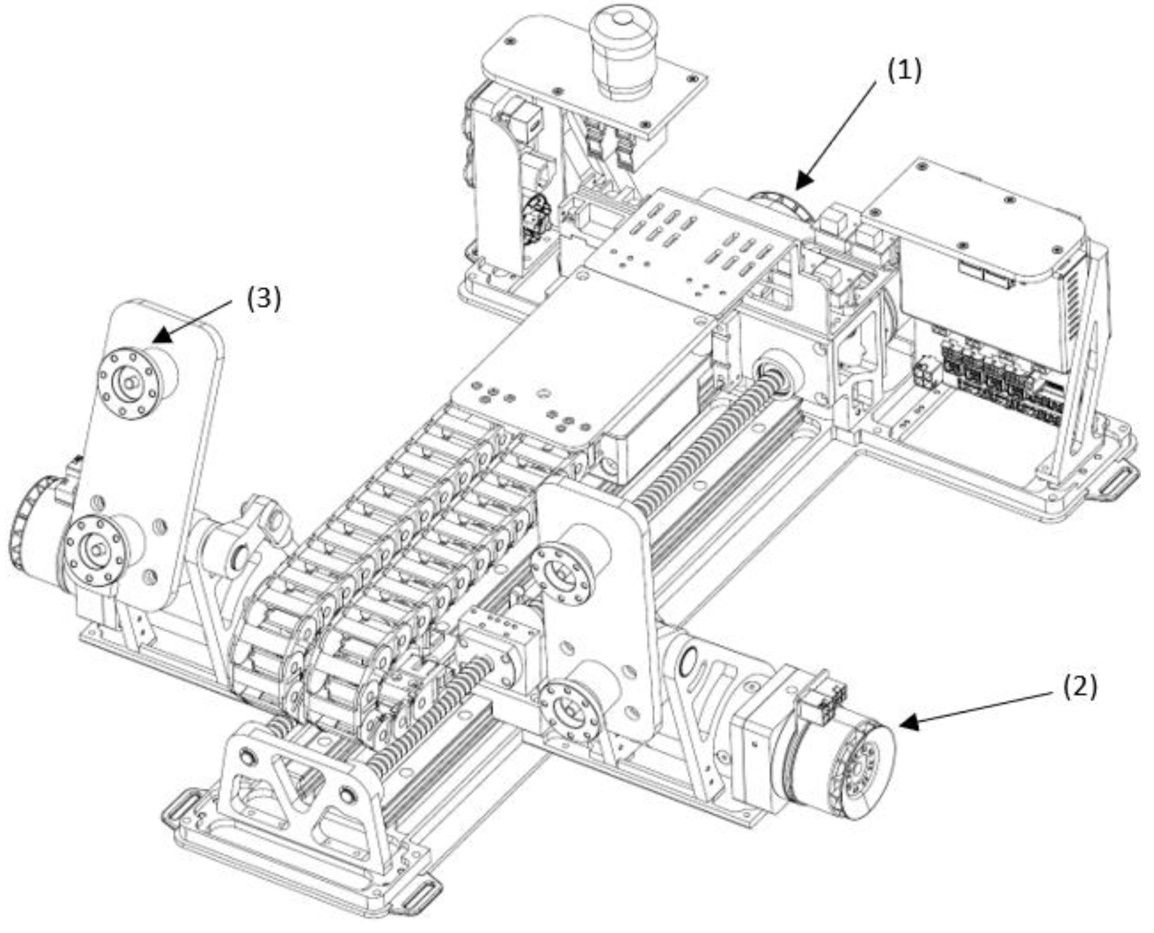
Figure 2). As shown in
Figure 1, four motors (EC60, maxon motor, Sachseln, Switzerland) were used to generate linear movement of the foot platform and ankle joint rotation. The linear movement of the foot platforms was achieved by using two motors with two screw drives. The rotation of the ankle joints was achieved by using the other two motors with gearbox (ratio of 40). Two force sensors (a maximal range of 500 N) were mounted under each foot platform to measure the active force from the user.
A 4-axis hardware motion controller (MiniMACS 50/10) was used in this study to control the movement. Position and force control algorithms were developed in ApossIDE (Version 7.00, maxon motor, Switzerland). Each leg has three training patterns: i) passive ankle dorsiflexion/plantarflexion; 2) passive linear foot training with synchronised ankle movement; and 3) active leg pressing.
2.2. Movement Control Strategies
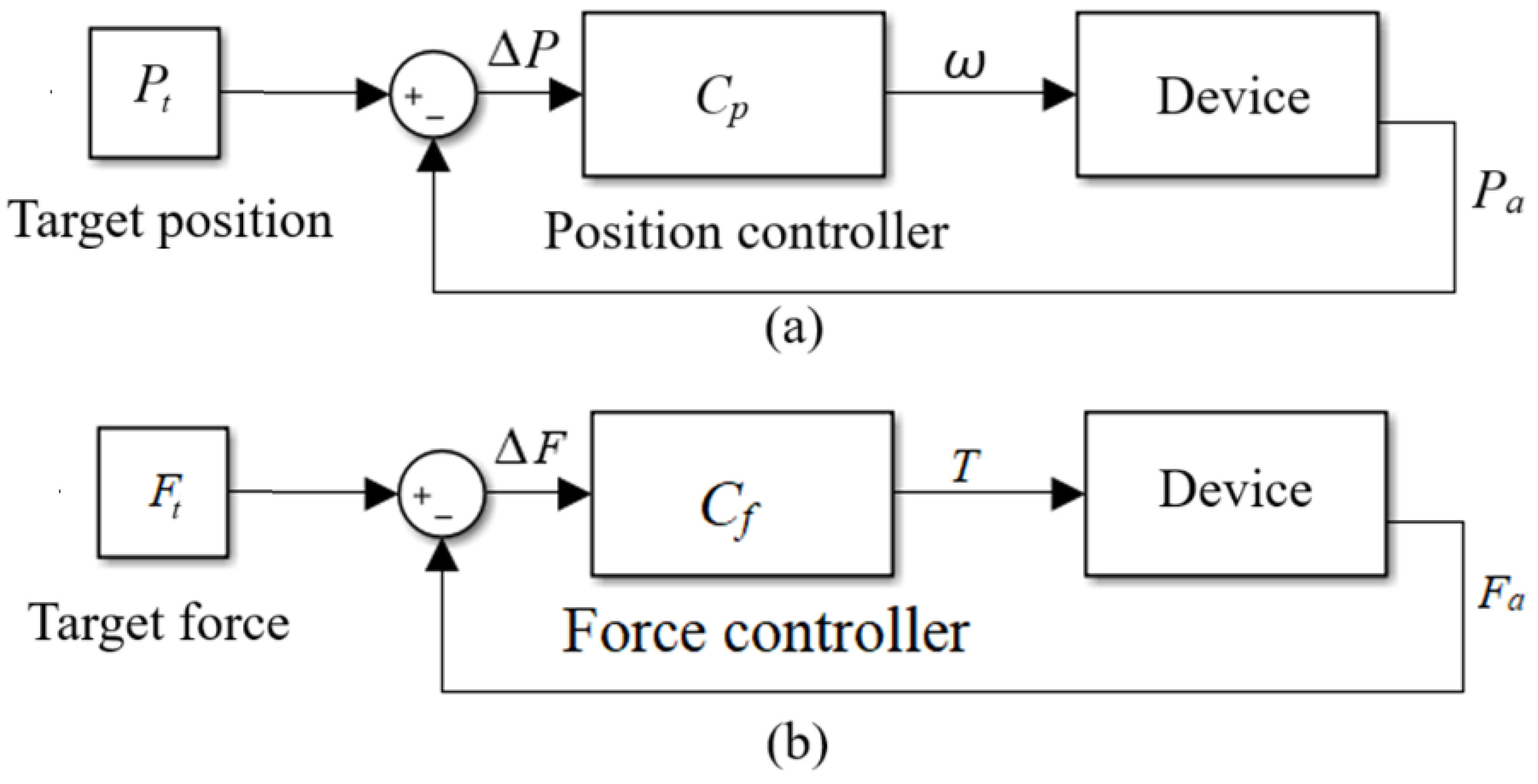
In order to produce the three types of training described above, passive position (
Figure 3a) and active force control algorithms (
Figure 3b) were developed. During passive mode, the target trajectories for the ankle dorsiflexion/plantarflexion and linear placement were given. The four motors were set to run in speed mode. The PID position controllers that were embedded in the motion controller were implemented in the four motors to produce the target trajectories. Parameter tuning was performed using the Scope function in ApossIDE.
In order to produce active training, the force control strategy (
Figure 3b) was implemented in the two motors with the screw drives to produce active loading during leg pressing. The motors were set to run in torque mode. The other two motors for the ankle rotation were blocked, that is, they ran in the passive position mode, where a constant ankle position of 0
o was defined as the target position.
2.3. System Programme Architecture
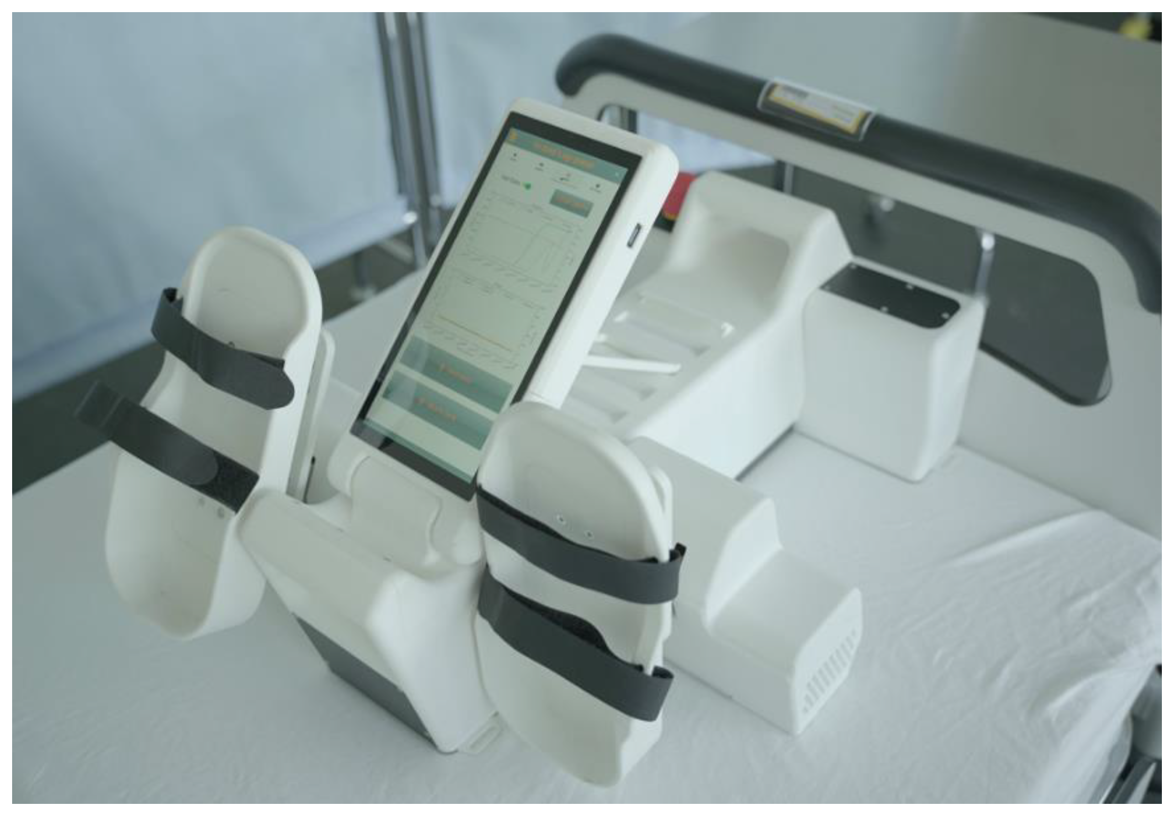
In order to make the system operation easier for the users, i.e., physiotherapists and patients, a touch screen (
Figure 2) with an embedded system programme on Raspberry Pi was used. The primary software for the system was developed in PyCharm (Version 2023.3.4, JetBrains). The Integrated Development Environment facilitated the development of the main application in Python. Additionally, Visual Studio Code (Version 1.91, Microsoft) was used for direct programming on the Raspberry Pi. The SSH extension of Visual Studio Code allowed seamless remote access and file management on the Raspberry Pi, providing a smooth and efficient development directly on the device.
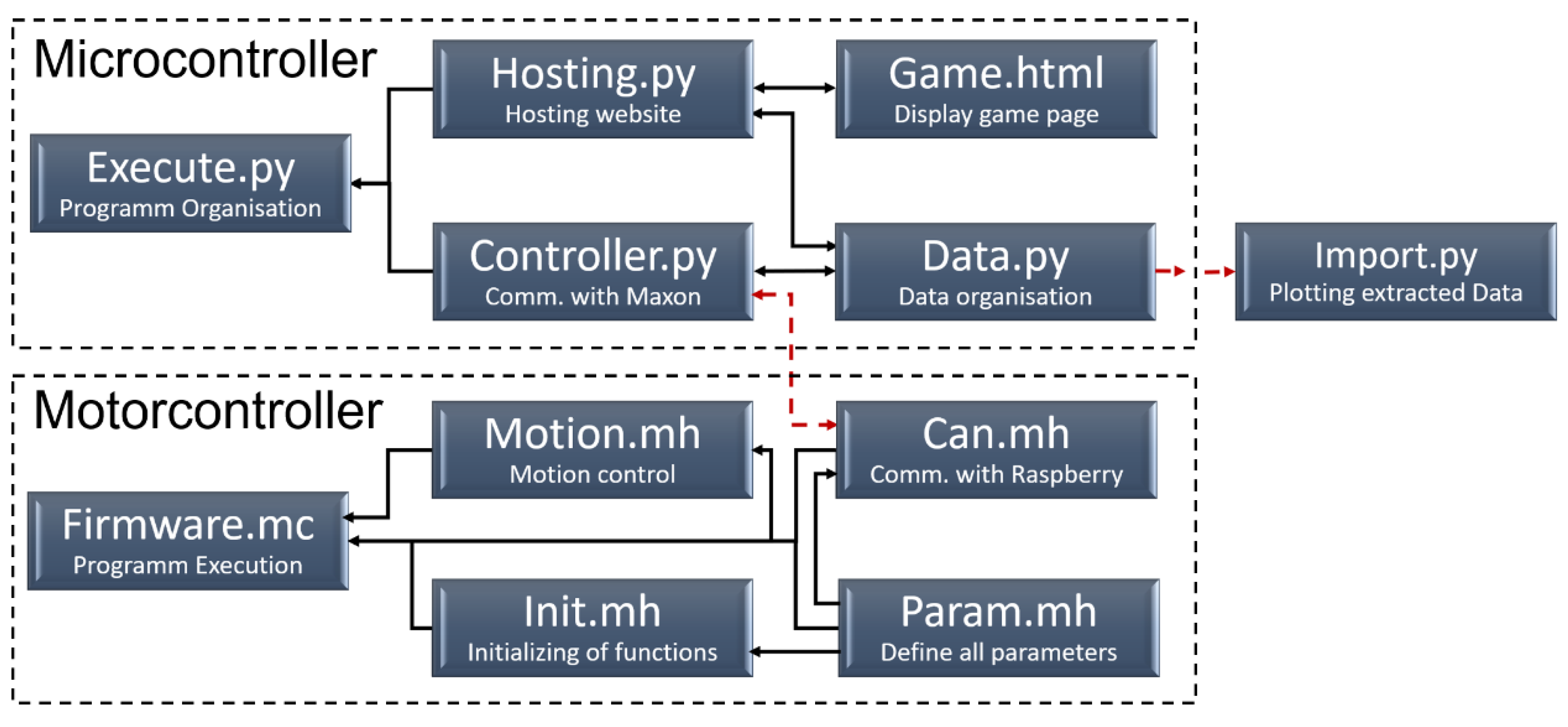
The programme was divided into two main components (
Figure 4). Its architecture was designed to ensure that communication was initiated and controlled by the main programme through queries and the continuous transmission of commands. The scripts Firmware.mc, Motion.mh, Can.mh, Init.mh and Param.mh operated on the standalone MiniMACS controller. This configuration facilitated the automatic start function and initialised the PID control parameters for both position and force control. In contrast, the scripts “Execute”, “Hosting”, “Controller” and “Data” were executed on the Raspberry Pi. CAN communication between the Raspberry Pi and the MiniMACS was facilitated by both the Can.mh script on the MiniMACS and the “Controller” script on the Raspberry Pi. The “Hosting” script utilised the "nicegui" library, employing its tools and building blocks to provide a comprehensive user interface (
Figure 5) and establish connections to the implemented exergames (See
Section 2.4). All data and overarching variables were securely stored within the “Data” script, which included a locking mechanism to prevent simultaneous access by multiple processes. These variables could then be exported and accessed via the “Import” script.
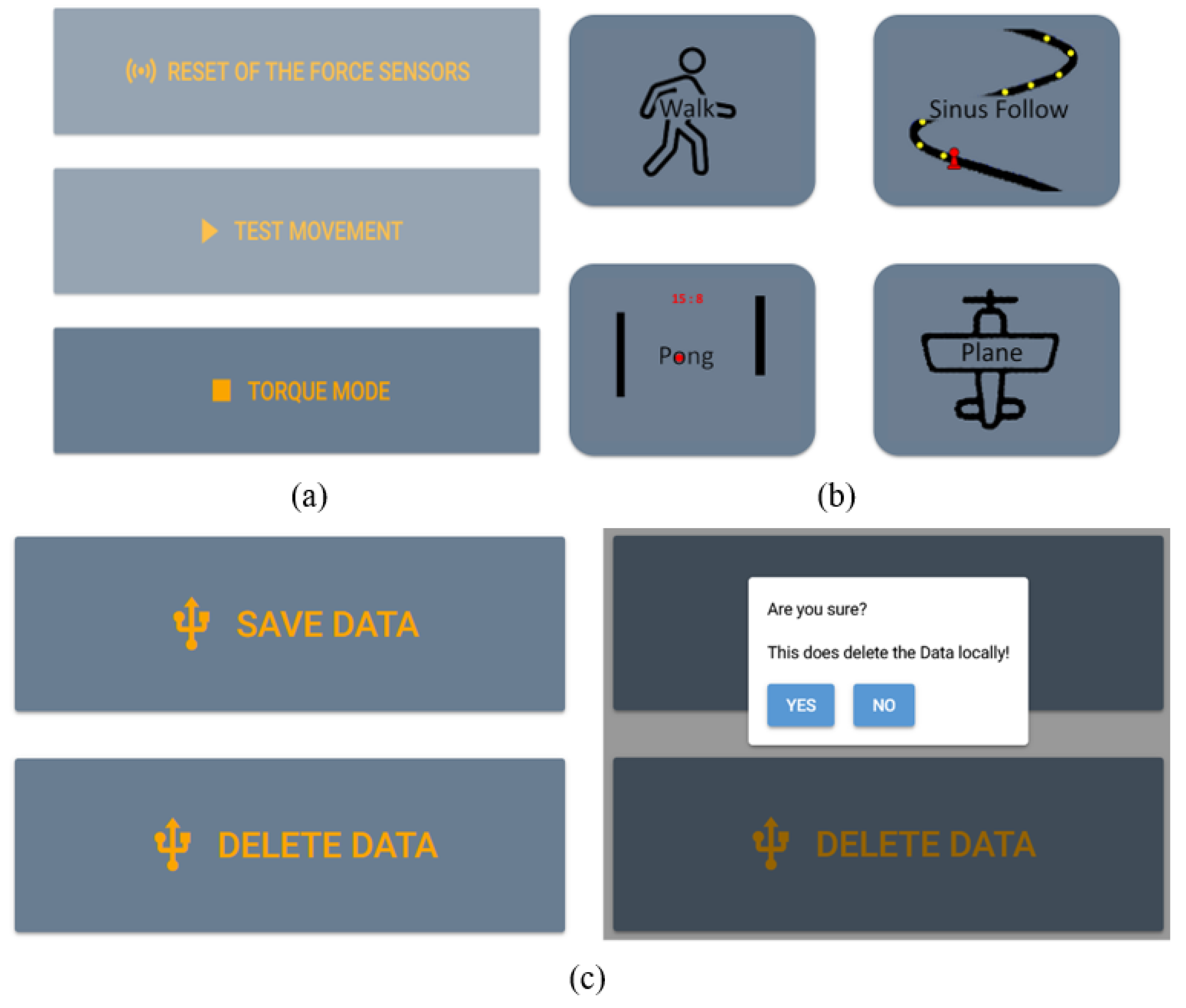
Regarding the user interface, three pages were created: Testing (
Figure 5a), Computer Game (
Figure 5b) and Data (
Figure 5c). On the Testing page, tabs for force sensor calibration, initial movement testing and motor mode selection were created. On the Computer Game page, several games could be selected. On the Data page, there were graphs to monitor the data and buttons to save or delete training data (
Figure 5c). The user interface allowed the user to start/stop the system, to set target force position profiles and to view the training results. The target/actual force and position of the foot plates, and the motor torque were saved using the data-saving package.
2.4. Development of the Computer Games
To encourage users to actively participate in training, computer games (
Figure 5b) were incorporated into the training programme. The exercise games were developed through the employment of the Godot Engine (Godot 4, Godot). It synchronised the leg movement with the animation of the games. The movement path was predefined in the computer game engine. The moving object could be controlled by pressing the right or left foot plates with a certain displacement. The linear position difference between both feet was sent to the computer game to define the position of the moving point.
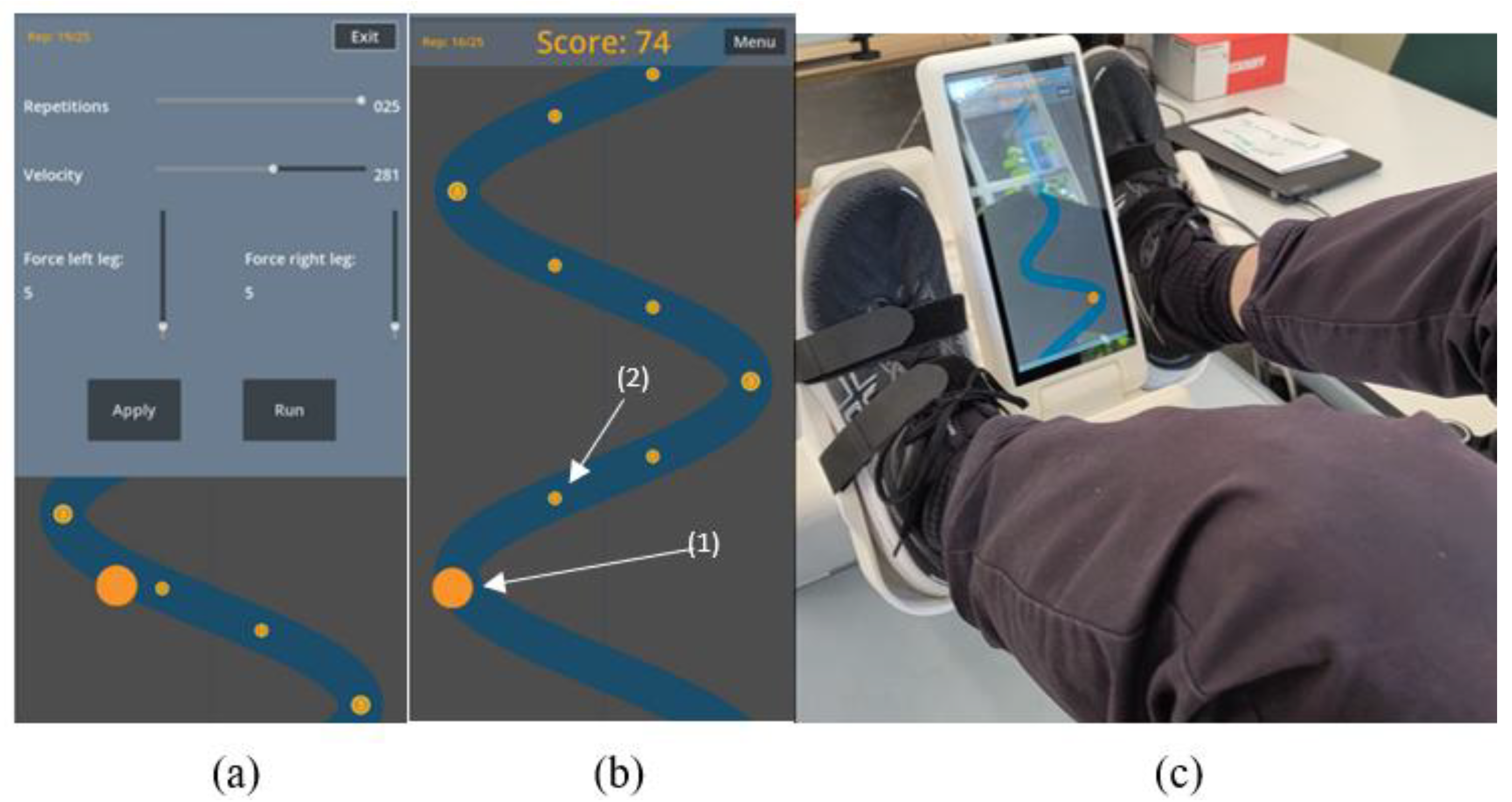
During training with the game, force control algorithms were implemented on both legs. As shown in a computer game example of a sinusoidal curve, the target force and the moving speed of the simulation point were defined (
Figure 6a). The main task of the game was to control the yellow circle to collect coins, which are smaller objects scattered on the path (
Figure 6b). The participant interacted with the computer game by moving the legs, so that the movement followed the defined path on the screen (
Figure 6c).
2.5. Evaluation Test
In order to evaluate the functionality, a test was carried out with 12 able-bodied participants (mean age 32.5 years, mean height 1.80 m,
Table 1). The study did not fall under the Swiss Human Research Act because it did not investigate human pathology or physiology, nor did it involve the collection of health-related data [
14]. Therefore, no ethical approval was required.
The participant lay on the therapy bed in a recumbent position with their feet on the foot platforms of the device. Then the participant familiarised themselves with the functions of the device. Lastly, they rested for 1 min before the start of the formal test. Three sessions were tested: training in passive, active and game sessions. Each session consisted of 10 reciprocal leg movements and was repeated three times. The break between each repetition was approximately 30 seconds. In the passive session, the participant followed the movement produced by the foot platforms. The target movements were sinusoidal positions in the linear axis and the rotational ankle joint. The movement had a range of 300 mm displacement and 30o rotation in the ankle joint. In the active session, the participant pressed against the foot platforms so as to stretched both legs reciprocally. They moved to the beat of a metronome. In the game session, the participant pressed against the foot platforms and moved both feet so as to follow the trajectory path shown in the computer game and collect as many coins as possible. During the active and game sessions, a target force of 50 N for both feet was defined.
After the participant finished the test, they filled out a questionnaire. Seven questions were related to mechanics and movement control, which are whether
(1.1) the participant liked the appearance;
(1.2) the participant had a positive impression of the overall device;
(1.3) the participant found it convenient to transport the device;
(1.4) the participant found the device easy to use;
(1.5) the participant was happy about the interaction / reaction speed during use;
(1.6) the participant was comfortable with the force intensity during the exercise;
(1.7) the participant felt physically good while and after exercising with the device.
The questions regarding the user interface and computer game included whether
(2.1) the game was engaging and kept their interest throughout the training;
(2.2) the training using the game was more exciting than the one without the game;
(2.3) the game ran smoothly without delay;
(2.4) the user interface was clear and easy to navigate;
(2.5) the test results gave you a strong sense of achievement;
(2.6) the participant would recommend this device to their friends.
The answers to the questions were in a scale of 5, where “1” to “5” means “strongly disagree”, “disagree”, “neutral”, “agree” and “strongly agree”, respectively.
The data of each movement session were analysed. The accuracy of force control was calculated using the root-mean-square error (RMSE) between the target force
Ft and the actual force
Fa:
where
N is the number of data points in the interval
to and
t1. Replacing the force with positions in Eq. (1), the accuracies of position control of the four motors were calculated.
3. Results
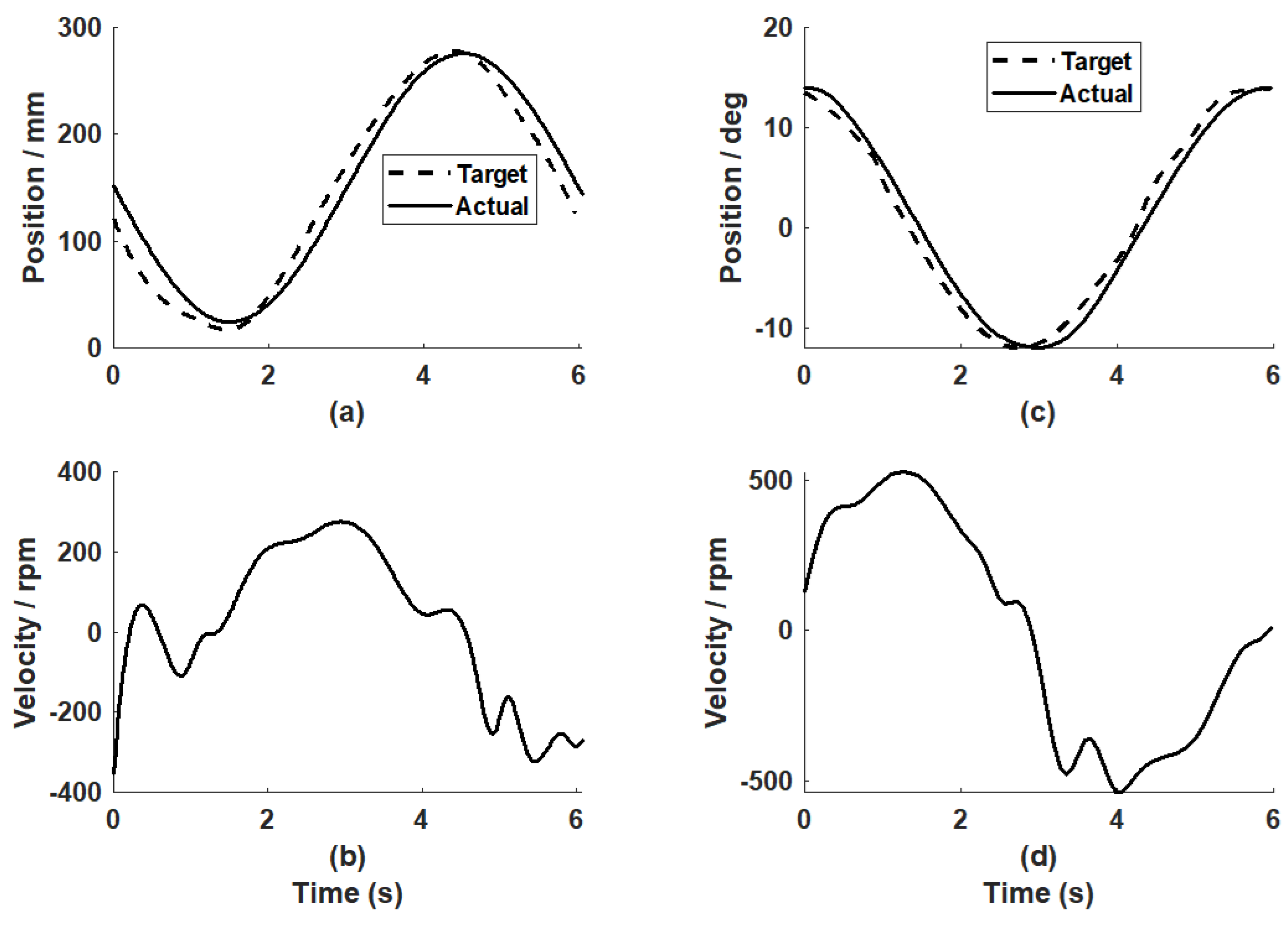
The passive mode was tested with the target positions for both legs as the sinusoidal trajectories (
Figure 7). The PID controller parameters for the linear motors were
kP = 40,
kI = 0.25 and
kD = 400. Regarding the motors for ankle rotation, the PID parameters were
kP = 15,
kI = 0.25 and
kD = 25. The position control accuracies from a representative participant (P5) were 17.69 mm for the linear movement and 1.28
o for the ankle joint.
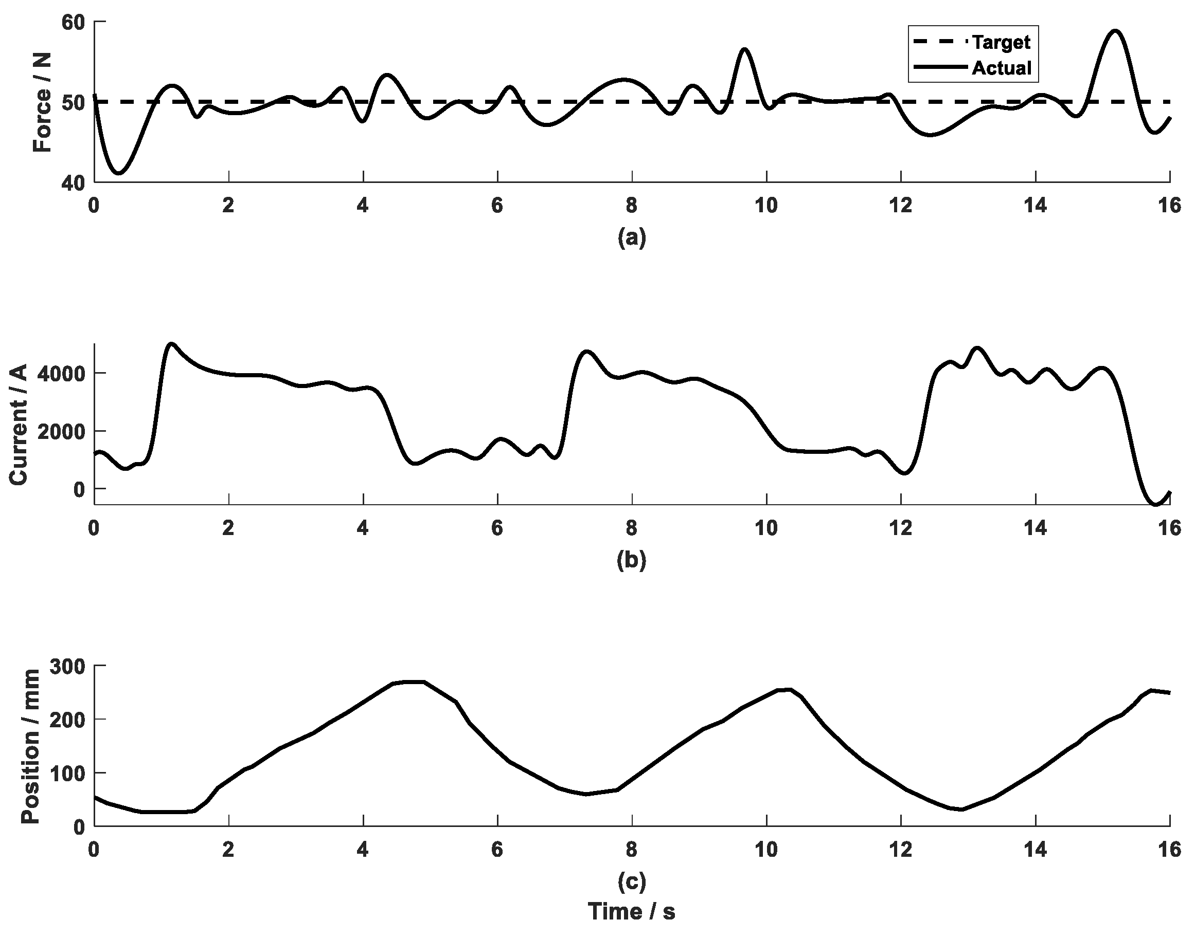
In the active mode (
Figure 8), a constant target force of 50 N was tested. The control parameters for the two linear actuators were set to be
kP = 1.5,
kI = 0.25 and
kD = 0.05. The force control error of the representative participant was 4.57 N. The error mainly came from the linear movement of the leg. During the test, the leg movement varied in a range of 200-300 mm (
Figure 8c), where the actual range of movement was controlled by the individual participant.
Summarising the test results of the 12 participants, the position control error for the linear position was 18.96 mm, and 2.27o for the ankle joint rotation. The force control accuracy was 6.98 N.
All participants completed the questionnaire (
Table 2 and
Table 3). Regarding the mechanics and movement control, all participants agreed or strongly agreed that they liked the appearance (Q1.1) and felt comfortable with the force intensity during the exercise (Q1.6). 11 participants agreed or strongly agreed that they obtained a positive impression of the overall device (Q1.2). Ten participants agreed or strongly agreed felt physically good while and after exercising with the device (Q1.7). The only participant who disagreed regarding physical feeling from usage of the system commented that the training bed, with the allowable length for the participant’s legs as 0.86 m, was too small compared to his height of 1.93 m. Nine participants agreed or strongly agreed that the device was easy to use (Q1.4). Four participants disagreed with the statement that the device was convenient to transport (Q1.3) due to the weight of the device (approximate 18 kg). A trolley or an automatic cart was recommended. Only five participants agreed or strongly agreed that they were happy about the interaction / reaction speed during use (Q1.5). The answer was related to Q 2.3, where six participants commented on the long delay of the simulated movement of the yellow point and the actual leg movement.
Regarding the computer game, 11 participants agreed or strongly agreed that the game was engaging and kept their interest throughout (Q2.1), and the training using the game was more exciting than the one without the game (Q2.2). Eight participants thought the user interface was clear and easy to navigate (Q2.4), while the remaining four participants were neutral to this statement and commented that a user manual page or an introduction would be desirable. As described above, six participants disagreed about the statement that the game ran smoothly without delay (Q2.3). In spite of the delay between the actual and simulated movement, nine participants agreed or strongly agreed that the test results yielded a strong sense of achievement (Q2.5). Ten participants wanted to recommend this to their friends (Q2.6). One felt that the system reaction speed required to be improved before a recommendation could be made, while the other wanted to recommend a lighter system for the sake of easy transport.
4. Discussion
To prevent prolonged inactivity, early mobilisation is key where a robotic device offers the potential to promote such mobilisation in bed. The first iteration of a user-centred design process for such a device [
6] resulted in clear user requirements of light weight and easy operation, active and passive training with exergames. This work developed and evaluated an in-bed lower-limb therapy device that provides various training patterns for the foot and leg with an intuitive user interface and interactive computer games. Four motors produced bilateral leg pressing with synchronised ankle dorsiflexion/plantarflexion. Using the touch screen, the system was operated conveniently to provide passive training with a user-defined range of movement and active training with a computer game. Preliminary testing on 12 able-bodied participants showed that the system produced training with acceptable accuracy. The user interface with the interactive computer game was tested technically implementable.
This study developed a portable stand-alone device, which could easily be operated to provide training on the bilateral legs and ankle joints for the bed-resting users. For such weak users during the bed-resting phase, passive position control is an important training mode. The position control algorithms enabled the device to produce acceptable results in passive mode. The ankle joint is important in daily living and sports activities. It stabilises the leg and provides dynamic energy for the lower limb to interact with the ground [
15]. A powerful ankle joint is essential for normal gait. Therefore, plantarflexion/dorsiflexion training was considered as a required function of the device. Compared to our first pneumatic model [
13], the current device used electric motors for production of leg pressing and ankle joint training. Actuation of the bilateral legs and ankle joints required four drives, which were two linear and two rotary drives. Thanks to the advanced motion controller MiniMACS which enabled simultaneous control of four motors, the lower-limb therapy device had a compact control system. Feedback from the participants showed that they generally liked the device appearance and were satisfied with the system operation.
The force control algorithms provided satisfactory results in active mode, but better control strategies will be investigated. In order to ensure effective training, the physical guidance should be adapted to varying needs as the training progresses [
12,
16]. After a certain period of passive training, users may progress in the rehabilitation with some recovery of voluntary control. Then training with active loading on the lower limbs is required. Due to the limited control blocks provided by the ApossIDE library, the current study used the PID control strategy that was embedded in the motion controller. The force control accuracy of 6.98 N was considered acceptable. However, the control algorithms could be improved. It is possible to control the motors in ApossIDE by self-developed control blocks. Force control can be improved by implementing algorithms designed through the pole-assignment approach [
17]. In addition, the test results showed that the force control accuracy was strongly influenced by the movement of the foot platform. Disturbance from the velocity is a common issue in force control [
18]. The force control strategy of the lower-limb therapy device can be improved by integrating a velocity compensator. Such improved control strategies will be investigated further.
The computer game was tested to be interesting and easy to use and it encouraged the participants into active participation throughout the training. There are several approaches to developing computer games, such as using a head-mounted display [
19], or the Unity 3D game engine [
20]. They often involve many cables and/or require a powerful desktop computer. However, the interviews with physiotherapists [
6] defined the requirements of the device to be easy to operate. Therefore, a stand-alone platform using Raspberry Pi was selected. The system was conveniently operated via a touch screen. The interactive computer game motivated the participants during the training. The user interface showed the training results graphically. The biofeedback and computer games can potentially be viewed through smartphones. Testing with the participants showed that the user interface was intuitive to navigate, and the interactive computer game engaged the participants during the training. Although the current exergame approach was tested as feasible, the computer simulation response needs to be improved. During the test, half of the participants thought the delay between the actual and simulated movement in the computer game was too long. A more powerful microcomputer will be investigated in the future.
Apart from validating the technical feasibility of the device, the preliminary tests additionally yielded aspects for improvement. The prototype should be improved from the operators' and participants' perspective. The ankle rotation mechanisms have some play compared to the limited rotation range. Four participants were concerned about the comfort of transferring the device. This is understandable, as the device was about 18 kg due to the motors and gears. Additionally, the power unit had to be transported along with the device. Some participants also noted that the platform tended to move away during foot strapping in the user-setup phase. To address this, a strap-in mode could be added to hold the foot platforms in place. These findings emphasise the need for adjustments in the mechanical design and system programme to improve user satisfaction and operational comfort.
5. Conclusions
By automatically controlling four motors, the lower-limb therapy device produced leg flexion/extension with synchronised plantarflexion/dorsiflexion, and linear leg pressing with active loading. The portable in-bed device managed to provide various training patterns with satisfactory accuracies. The integration of the user interface and exercise games into the prototype encouraged the users to practise with active participation. The system showed potential to be applied for users to train lower limbs in the bed-rest phase.
Author Contributions
Conceptualisation, J.F., A.C. and K.S.; methodology, J.F. and A.C.; software, S.G.S. and P.v.R; validation, J.F., S.G.S. and P.v.R.; formal analysis, J.F. and P.v.R.; investigation, J.F., A.C., S.G.S., P.v.R. and K.S.; writing—original draft preparation, J.F.; writing—review and editing, A.C., S.G.S., P.v.R. and K.S.; supervision, J.F., A.C. and K.S.; project administration, , J.F. and A.C.; funding acquisition, J.F. and A.C. All authors have read and agreed to the published version of the manuscript.
Funding
This project received funding from the Junior Scholars Program (J.012016-20-HUCE), an internally funded transversal project of Bern University of Applied Sciences.
Data Availability Statement
Data are contained within the article.
Conflicts of Interest
The authors declare no conflicts of interest.
References
- Bernhardt, J.; English, C.; Johnson, L.; Cumming, T.B. Early mobilization after stroke: Early adoption but limited evidence. Stroke. 2015, 46, 1141–6. [Google Scholar] [CrossRef] [PubMed]
- Parry, S.M.; Puthucheary, Z.A. The impact of extended bed rest on the musculoskeletal system in the critical care environment. Extreme physiology & medicine 2015, 4, 16. [Google Scholar]
- Kuys, S.S.; Dolecka, U.E.; Guard, A. Activity level of hospital medical inpatients: an observational study. Archives of gerontology and geriatrics. 2012, 55, 417–21. [Google Scholar] [CrossRef] [PubMed]
- Hodgson, C.L.; Capell, E.; Tipping, C.J. Early Mobilization of Patients in Intensive Care: Organization.; Communication and Safety Factors that Influence Translation into Clinical Practice. Critical Care 2018, 22, 77. [Google Scholar] [CrossRef] [PubMed]
- Boulanger, J.; Lindsay, M.; Gubitz, G. Canadian Stroke Best Practice Recommendations for Acute Stroke Management: Prehospital, Emergency Department, and Acute Inpatient Stroke Care, 6th Edition, Update 2018. International Journal of Stroke 2018, 13, 949–984. [Google Scholar] [CrossRef] [PubMed]
- Cerrito, A.; Fang, J.; Schertenleib, S.J.G.; Hunt, K.J.; Schmitt, K.-U. First iteration of a User-Centered Design process to develop an in-bed leg press. Technology and Health Care 4637, 32, 4637–4651. [Google Scholar] [CrossRef] [PubMed]
- Brockmann, L.; Saengsuwan, J.; Schuster-Amft, C.; Hunt, K.J. Feedback control of heart rate during robotics-assisted tilt table exercise in patients after stroke: a clinical feasibility study. Journal of NeuroEngineering and Rehabilitation. 2024, 21, 141. [Google Scholar] [CrossRef] [PubMed]
- Warmbein, A.; Hübner, L.; Rathgeber, I.; Mehler-Klamt, A.C.; Huber, J.; Schroeder, I.; et al. Robot-assisted early mobilization for intensive care unit patients: Feasibility and first-time clinical use. International Journal of Nursing Studies. 2024, 152, 104702. [Google Scholar] [CrossRef] [PubMed]
- Nickels, M.R.; Aitken, L.M.; Barnett, A.G.; Walsham, J.; McPhail, S.M. Acceptability, safety, and feasibility of in-bed cycling with critically ill patients. Australian Critical Care. 2020, 33, 236–43. [Google Scholar] [CrossRef] [PubMed]
- Eggmann, S.; Verra, M.L.; Luder, G.; Takala, J.; Jakob, S.M. Effects of early, combined endurance and resistance training in mechanically ventilated, critically ill patients: A randomised controlled trial. PLoS One. 2018, 13, e0207428. [Google Scholar] [CrossRef] [PubMed]
- Fossat, G.; Baudin, F.; Courtes, L.; Bobet, S.; Dupont, A.; Bretagnol, A.; et al. Effect of In-Bed Leg Cycling and Electrical Stimulation of the Quadriceps on Global Muscle Strength in Critically Ill Adults: A Randomized Clinical Trial. Jama. 2018, 320, 368–78. [Google Scholar] [CrossRef] [PubMed]
- Brach, J.S.; Vanswearingen, J.M. Interventions to Improve Walking in Older Adults. Current translational geriatrics and experimental gerontology reports. 2013, 2. [Google Scholar] [CrossRef] [PubMed]
- Rostetter, R.; Jenni, B.; Eggmann, S.; Meyer, J.T.; Schmitt, K.-U. . Implementing an interprofessional user-centered design approach to develop a bedside leg exercise device. Technol Health Care 30, 981–992. [CrossRef] [PubMed]
- Fedlex. The publication platform for federal law. Federal Act on Research involving Human Beings: Human Research Act (HRA). 2023. [Google Scholar]
- Brockett, C.L.; Chapman, G.J. Biomechanics of the ankle. Orthop Trauma. 2016, 30, 232–8. [Google Scholar] [CrossRef] [PubMed]
- Schmidt, R.A.; Young, D.E.; Swinnen, S.; Shapiro, D.C. Summary knowledge of results for skill acquisition: Support for the guidance hypothesis. Journal of Experimental Psychology: Learning, Memory, and Cognition 1989, 15, 352–359. [Google Scholar] [CrossRef] [PubMed]
- Chrif, F.; Nef, T.; Lungarella, M.; Dravid, R.; Hunt, K.J. Control design for a lower-limb paediatric therapy device using linear motor technology. Biomedical Signal Processing and Control. 2017, 38, 119–27. [Google Scholar] [CrossRef]
- Fang, J.; Haldimann, M.; Marchal-Crespo, L.; Hunt, K.J. Development of an active cable-driven, force-controlled robotic system for walking rehabilitation. Frontiers in Neurorobotics. 2021, 15. [Google Scholar] [CrossRef] [PubMed]
- Wenk, N.; Buetler, K.A.; Penalver-Andres, J.; Müri, R.M.; Marchal-Crespo, L. Naturalistic visualization of reaching movements using head-mounted displays improves movement quality compared to conventional computer screens and proves high usability. Journal of NeuroEngineering and Rehabilitation. 2022, 19, 137. [Google Scholar] [CrossRef] [PubMed]
- Kamnardsiri, T.; Phirom, K.; Boripuntakul, S.; Sungkarat, S. An interactive physical-cognitive game-based training system using kinect for older adults: development and usability study. JMIR Serious Games. 2021, 9, e27848. [Google Scholar] [CrossRef] [PubMed]
|
Disclaimer/Publisher’s Note: The statements, opinions and data contained in all publications are solely those of the individual author(s) and contributor(s) and not of MDPI and/or the editor(s). MDPI and/or the editor(s) disclaim responsibility for any injury to people or property resulting from any ideas, methods, instructions or products referred to in the content. |
© 2024 by the authors. Licensee MDPI, Basel, Switzerland. This article is an open access article distributed under the terms and conditions of the Creative Commons Attribution (CC BY) license (http://creativecommons.org/licenses/by/4.0/).