Submitted:
29 November 2024
Posted:
29 November 2024
You are already at the latest version
Abstract
Some of the consequences of earthquakes are permanent ground deformations caused by fault movement and propagation of fault rupture to the ground surface. Structural seismic design codes only recommended avoiding construction near active faults and imposing a setback zone from the fault lines to prevent fault rupture surface cross structures. Avoiding construction across or near active faults is impossible for long structures, such as tunnels and pipelines. Therefore, appropriate measures should be taken to mitigate the fault rupture hazard. In this paper, hazard mitigation strategies in the interaction between the fault and the subsurface structures, which are categorized into structural and geotechnical approaches, are investigated. Structural strategies include reinforcing the part of the structure that is under faulting and using flexible joints, and geotechnical strategies include isolation techniques using different materials between the tunnel lining and the soil, using sliding rigid elements or soft elements for deviation of the rupture path. Studies have shown that the fault type, the relative position of the underground structure to the fault plane, and its buried depth are among the factors affecting the efficacy of the proposed methods. The investigated solutions and their conditions can be a guide for practical engineering.
Keywords:
Fault Rupture
; Underground Space
; Hazard Mitigation
; Ground Deformations
1. Introduction and Background
It has long been believed that underground structures experience less damage in earthquakes than above-ground structures (Dowding and Rozan, 1978). However, in severe earthquakes such as Izu-Oshima-Kinkai (1978), Kobe (1995), and Kumamoto (2016) in Japan, Düzce (1999) in Turkey, Chi-Chi (1999) in Taiwan, and Wenchuan (2008) in China, the failures and collapses of underground structures have been observed (Kawakami, 1984; Nakamura et al., 1996; Sugimura et al., 2001; Dalgic, 2002; Kontogianni and Stiros, 2003; Yu et al., 2016; Kiyota et al., 2017). Field observations in these earthquakes showed that these structures are more vulnerable to permanent ground deformation (PGD) caused by faults than to shaking caused by seismic wave propagation. During the 1906 San Francisco and 2008 Wenchuan earthquakes, offsets of 1.8 m and 0.8 m were observed in the surrounding rock in the tunnels crossing the fault zone, respectively, which led to cave-in, deformation, and cracks in the tunnels (Prentice and Ponti, 1997; Cui et al., 2018). After the Chi-Chi earthquake (1999), 57 tunnels were investigated, and it was found that 49 tunnels suffered various damages (Wang et al., 2001). Damage to some underground structures due to fault rupture in large earthquakes is shown in Figure 1. In general, the three factors of ground failure (such as liquefaction or landslides), fault displacement, and ground shaking, which can also be found combined, cause cracking or failure in a tunnel (Lanzano et al., 2008).
Figure 1.
Damage to underground structures; a) Pipeline offset near San Andreas Lake in the 1906 San Francisco earthquake (Bray and Kelson, 2006), b) Chi-Shue tunnel after the 1999 Chi-Chi earthquake (Wang et al., 2001), c) Axial compression failure in Tawarayama tunnel Caused by the 2016 Kumamoto Earthquake (Kiyota et al., 2017), d) Collapse of tunnel liner and exposed impermeable lining during the 2008 Wenchuan earthquake (Yu et al., 2016).
The use of subsurface structures to accommodate critical lines such as roads, subways, and water and gas transportation systems is increasing. Many cities are located in active fault zones, which creates challenges for the construction of these subsurface structures. The recommendation of seismic design codes is simply to avoid construction near active faults and to impose a setback zone from fault lines for the construction of structures (Hart et al. 1999; Boncio et al. 2018). The uncertainty related to the mapping of active faults and the rupture propagation pattern through soil sediments has made the implementation of these guidelines difficult.
Moreover, long structures such as tunnels, pipelines, and bridges often intersect active faults or are located in their vicinity. Therefore, it is necessary to increase the safety of the structures in fault zones by providing solutions to reduce the hazards associated with fault rupture. Over-excavated sections of tunnels to provide sufficient space for fault displacement conditions have been suggested by some researchers (Wang et al., 2012; Romero and Caulfield, 2012). Hazard mitigation strategies in the interaction between the fault and the subsurface structures are categorized into structural and geotechnical approaches, which are investigated in this paper. Structural strategies include reinforcing the part of the structure that is under faulting and using flexible joints, and geotechnical strategies include isolation techniques using different materials between the tunnel lining and the soil, using sliding rigid elements or soft elements for deviation of the rupture path. The type and level of damage to subsurface structures are influenced by the fault type, their position in relation to the fault plane, their depth placement, the relative rigidity of the structure and the surrounding materials, and the fault width (Baziar et al., 2016; Kiani et al., 2016; Ghavami et al., 2019; Cai et al., 2019; Zhang et al., 2020. Ghavami et al., 2021; Zhang et al., 2023b), which should be considered in selecting the appropriate mitigation method.
2. Structural Strategies
By conducting centrifuge tests, Kiani et al. (2016) showed that the segmental tunnel lining has a greater ability to deform than the continuous one to eliminate the effects of normal faulting, and sudden failure does not occur in segmental tunnels subjected to normal faulting. The structural damage to the lining was very low due to the proper geometric performance of the segments and their joints. However, the tensile nature of normal fault leads to the separation of the segment rings, which causes the soil to collapse into the tunnel, and there is a possibility of a sinkhole forming on at-ground surface, which should be considered for its effects on ground structures. In another study, Kiani et al. (2017) compared the behavior of segmental tunnels in normal and reverse faults. Due to the compressive nature of the reverse fault, the segmental tunnels subjected to reverse faulting have better performance compared to normal faulting (Figure 2). On the other hand, the opening of spaces between the segmental rings at the joints in the reverse fault was much less than the normal fault. Also, the ground differential movements in normal fault are much higher than in reverse fault. The soil overburden thickness and fault dip angle are important parameters in the design of the tunnel lining. The positive effects of the sequential joints method by applying it to the Karaj water transfer tunnel in Iran have also been observed (Jalali, 2018).
Tohidifar and Moosavi (2020) used flexible joints in the continuous concrete tunnel lining to reduce the damages induced by the differential displacement of the reverse fault. In the centrifuge test, cast-in-place concrete lining in continuous tunnels was modeled in three segments (Figure 3). Flexible joints with low shear and bending stiffness (elastomeric rubber foam tubes) were used instead of common transverse expansion joints. The results indicated that the transverse flexible joints make tunnel behavior more consistent with soil deformations and reduce the damage that may occur in the tunnel lining. The fault dislocation has caused the closing of the gap of flexible joints between the successive segments, which has created a locking mechanism (the tunnel segments go partially inside each other) with the rotation and displacement of the middle segment.
Based on the damage analysis of the tunnel passing through the normal fault after the Wenchuan earthquake, the idea of designing different lengths of sectional tunnel linings with flexible joints was proposed to apply to the active fault area (Shen et al., 2020).
To design a flexible joint in the model test, steel wire mesh was glued together at the joint between the cross-sectional models, and the joint gaps were filled with plaster, then a rubber strap with high elasticity was glued outside the joint. Flexible joints lead to localized damage instead of global damage and effectively adjust the stress distribution of the surrounding rocks. The damaged flexible joints were easily repaired after the earthquake and could effectively prevent global damage to the tunnel lining.
The performance of the submarine tunnel with flexible connections against strike-slip fault was investigated by performing model tests and numerical simulations (Zhou et al., 2021). These connections were made with steel wire and flexible rubber (Figure 4). The results showed that there are no evident cracks in the structure of the tunnel lining, and tunnel deformation with these connections is S-shaped, so that tunnel lining segments have significant rotation. Increasing the thickness of the lining, reducing the length of the lining segments and reducing the tunnel diameter, and smaller width and less rigidity of flexible connections can be effective in improving the performance of these tunnels. In another research, fibre plastic concrete has been proposed as a flexible joint material in the strike-slip fault zone to accommodate bending and shear deformation (Zhao et al., 2019).
The effectiveness of flexible joints as a mitigating measure against the consequences of strike-slip and dip-slip fault rupture on buried pipelines has also been confirmed (Melissianos et al., 2016; Melissianos et al., 2017; Valsamis et al., 2020).
Considering that the mechanical properties of rocks around the tunnel in the fault zone are generally very weak and the stress and displacement in this area are higher than in other regions, Li and Gu (2014) investigated three different construction methods to protect the tunnel located in the fault zone using the finite element method: 1) Reinforced concrete 2) Bolting-shotcreting and reinforced concrete 3) Grouting and reinforced concrete (Figure 5). The numerical modeling results show that the stresses and displacements in the third method are less than the other methods (Figure 5).
Fiber-reinforced concrete has been used as a primary support in underground structures in the form of shotcrete due to its high compressive and tensile strength and suitable ductility (Jovičić et al., 2009; Xin et al., 2019; Zhao et al., 2021). Zeng et al. (2021) introduced basalt fiber reinforced concrete as a suitable material for constructing articulated sections and increasing the tunnel structure flexibility. The results of their studies showed that basalt fibers can increase the tensile strength of concrete, so that by applying the fiber volume contents of 0.5%, the size of cracks in the tunnel caused by the PGD are reduced by 33.45% and 38.11%, respectively. Wang et al. (2024) showed that steel-polypropylene fiber in tunnel lining concrete play an important role in anti-fault performance. The effectiveness of using fiber-reinforced concrete in the lining of tunnels crossing the fault has been investigated by other researchers (Cui et al., 2020; An et al., 2020; Zhang et al., 2024).
Zhang et al. (2023a) investigated the mechanical properties of tunnels supported by corrugated plate structures under strike-slip faulting. The optimal design of this protection method can be attained by regulating the reinforcement rigidity to achieve the maximum fault movement associated with different soil constraints.
3. Geotechnical Strategies
To reduce the friction between the soil and the buried pipes (caused by the PGD), which leads to the strains in the pipe wall, preventive measures have been suggested. Covering the pipeline trench with geotextile (Figure 6a) reduces the pipe-soil friction and increases the effective anchor length of the pipeline (Gantes & Bouckovalas, 2013). The results of experiments conducted by Monroy-Concha (2013) showed that the use of two layers of geotextile fabric is effective only if the pipe-trench wall distance is less than half the diameter of the pipe. By placing the pipe in prefabricated concrete culverts (Figure 6b), as a result of displacement of a strike-slip fault, by sacrificing the culverts, the pipe strains are significantly reduced and the possibility of pipe failure (tensile failure or local buckling) is decisively reduced (Gantes and Melissianos, 2016). Backfilling the pipe trench with materials such as loose granular soil, rubber-derived aggregates, and Expanded Polystyrene (EPS) geofoam can also be effective in protecting buried pipelines from PGD.
The effectiveness of using pumice (as low-density gravel (LDG) with high porosity) as backfill in a trench containing a pipeline (Figure 6c) subjected to reverse fault was investigated by conducting a series of centrifuge tests (Rojhani et al., 2022). The LDG backfill changes the deformation mechanism of the pipeline to beam buckling and does not bear any significant axial strain, which makes its performance safer and causes less damage to the pipeline. Preventing pipeline cracking shows that this method can be useful for pipes carrying flammable materials. Another material proposed for filling the buried pipeline trench is foam concrete, which significantly protects the pipeline under displacement caused by the normal fault due to its high homogeneity, lightweight, controllable strength, and self-compaction (Yang et al., 2024).
Analysis of physical modelling data by Sim et al. (2012) has shown that pipe installation in a tire derived aggregate backfill (Figure 6d) can reduce the bending moment caused by small vertical fault displacements by 74%. Keshvarian et al. (2004) also reported the effectiveness of rubber isolators between lining and rock in the Gavoshan tunnel at the intersection point of the Marwarid strike-slip fault in western Iran.
The use of geofoam blocks (Figure 7a) has been proposed to increase the safety of buried steel pipelines located in strike-slip fault zones at different pipeline-fault crossing angles (Rasouli and Fatahi, 2020). 3D finite element simulations using ABAQUS showed that Expanded Polystyrene (EPS) geofoam block surrounding pipelines are effective in reducing compressive and tensile strains caused by fault rupture and preventing local bulking in the pipelines. The deformability of geofoam blocks causes them to be compressed during fault rupture, and as a result, the pressure from the surrounding soil on the pipeline is reduced. It was also observed that with the presence of the geofoam blocks, the distribution of deformations and stresses caused by fault rupture over a wider length prevents pipeline failure. (Figure 7b). The success of remediation technique utilizing geofoam blocks for underground pipeline systems subject to fault dislocation has also been reported by Choo et al. (2007).
Yao et al. (2020b) suggested a new structure for a subway station to mitigate damages induced by normal faulting, which includes a rectangular cross-section and two rigid diaphragm walls (Figure 8). The walls are made of reinforced concrete connected to the two sides of the structure. Numerical studies showed that these rigid walls can effectively reduce the structure rotation due to friction with the surrounding soil and restrain the relative dislocation of the soil underneath the bottom slab. The diaphragm wall length, the position of the structure relative to the fault rupture, the structure buried depth, and the fault angle are key design factors.
The performance of the rigid diaphragm wall to protect surface structures located on the dip-slip fault zone has also been investigated by researchers (Oettle and Bray, 2013; Yao et al., 2020a).
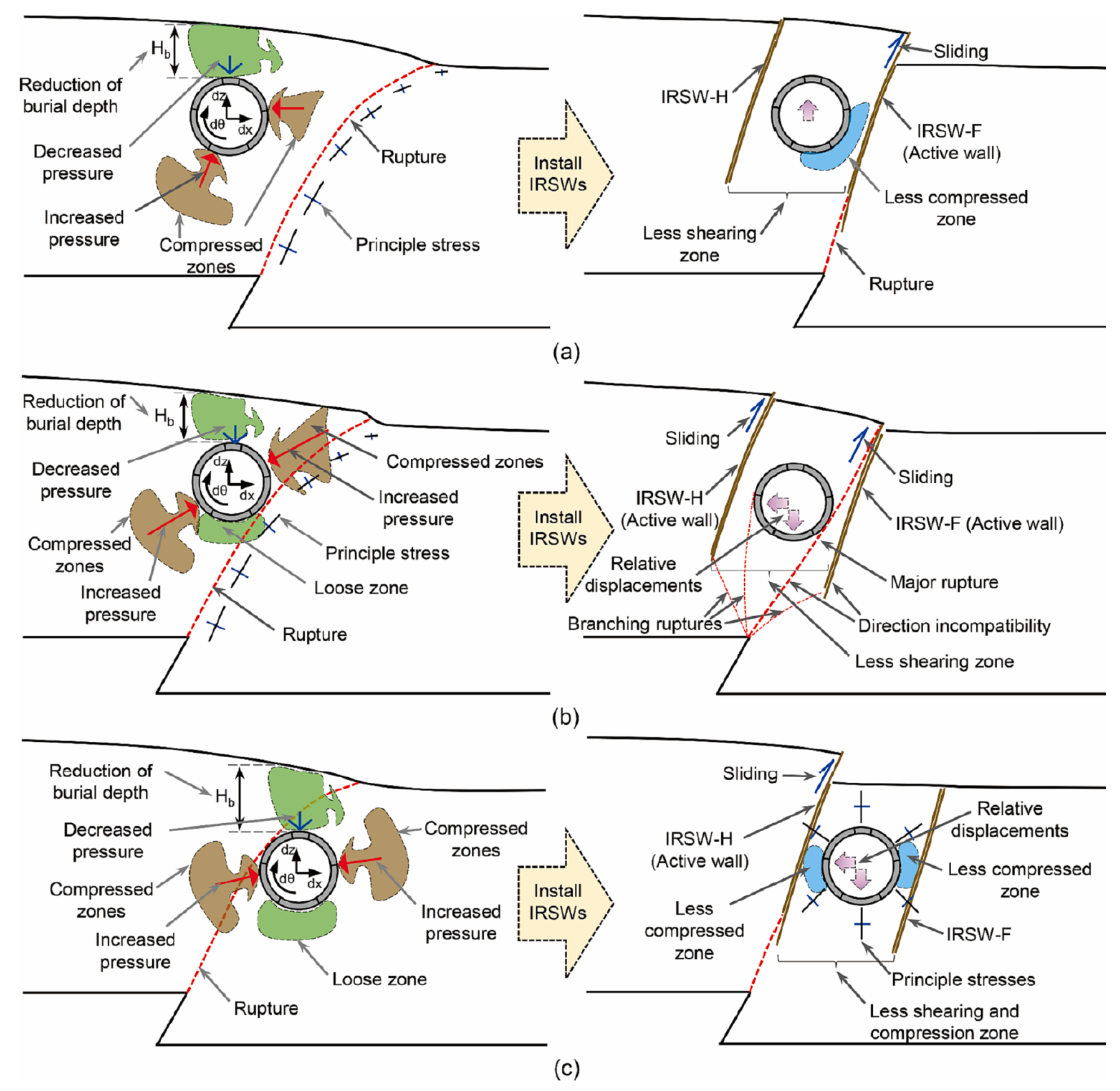
Yao et al. (2023) proposed the use of inclined rigid sliding walls (IRSW) as an effective method to protect shallow buried shield tunnels subjected to reverse fault rupture (Figure 9). Two groups of walls are placed on both sides of the tunnel, one in the footwall and the other in the hanging wall. Numerical modeling results showed that the protective effectiveness of the walls depends on the position of the tunnel relative to the fault rupture, the tunnel burial depth, the tunnel-wall distance, the wall deviation angle, the wall depth, and the fault dip angle.
Based on the effective parameters, there are three possible tunnel-walls-soil interaction mechanisms: hanging wall, footwall and shear mechanisms (Figure 9). In the hanging wall mechanism, the rupture propagates through the wall on the footwall side. This wall releases part of the deformation due to faulting. In addition to reducing the magnitude of stress and bending moment on the tunnel structure, the tunnel rotation is also reduced. In the shear mechanism, since the IRSW cannot divert the rupture from the tunnel due to the direction mismatch between the fault rupture and the wall, the tunnel condition is very dangerous. Despite not changing the distribution of stress and bending moment on the tunnel, their magnitudes are slightly decreased. The rotation and displacement of the tunnel are also mitigated. In the footwall mechanism, the rupture either stops at the bottom of the wall (located on the side of hanging wall) or propagates on the hanging wall side. This wall experiences a large sliding, which mitigates most of the horizontal and vertical deformations, leading to uniform distribution of stress and bending moment with smaller values, and as a result, the structural damage to the tunnel is prevented.
The deviation of the rupture path along the inclined rigid wall with high shear strength and preventing the rupture from reaching the structures has also been discussed in the studies conducted by Saeedi Azizkandi et al. (2021) and Baziar and Rashedi (2022).
The effectiveness of expanded polystyrene (EPS) sheet walls near the shallow foundation on fault rupture-foundation-tunnel interaction has been investigated by Saeedi Azizkandi et al. (2019). The soft vertical walls (made of materials such as bentonite and EPS) divert the rupture path and prevent the rupture from reaching the structures (Fadaee et al., 2016; Sadra et al., 2020; Shidloon et al., 2024). It seems that this technique can be effective for tunnels and pipes with a shallow buried depth, parallel to the revers fault plane.
4. Conclusions and Recommendations
This research investigated structural and geotechnical strategies to mitigate the fault rupture hazard for underground structures. Structural strategies include reinforcing the part of the structure under faulting and using flexible joints when the tunnel or pipeline axis intersects the fault plane. Geotechnical strategies include isolation techniques using different materials between the tunnel lining and the soil, using sliding rigid elements or soft elements for deviation of the rupture path. The fault type, the relative location of the underground structure to the fault plane, and its placement depth are among the factors influencing the efficiency of the proposed methods. Rigid and soft elements are used when the tunnel or pipeline axis is parallel to the dip-slip fault plane. Flexible joints in the tunnel lining are used in the condition of crossing the tunnel axis with the fault plane. The selection of a mitigation strategy should be done in a technical-economic framework. In addition to the feasibility of the measures for existing or new structures, the cost of construction, production, and transportation of materials and excavation should be considered.
References
- An, D., Chen, Z., Meng, L., Cui, G. (2020). Application of fiber-reinforced concrete lining for fault-crossing tunnels in meizoseismal area to improving seismic performance. Advances in Mechanical Engineering, 12(7). [CrossRef]
- Baziar, M. H., and Rashedi, M. M. (2022). Use of V-shaped concrete element to mitigate foundation rotation for uncertain reverse faulting dip angle and discontinuity location. Soil Dynamics and Earthquake Engineering, 158, 107287. [CrossRef]
- Baziar, M. H., Nabizadeh, A., Mehrabi, R., Lee, C. J., & Hung, W. Y. (2016). Evaluation of underground tunnel response to reverse fault rupture using numerical approach. Soil Dynamics and Earthquake Engineering, 83: 1-17. [CrossRef]
- Boncio, P., Liberi, F., Caldarella, M., Nurminen, F. C. (2018). Width of surface rupture zone for thrust earthquakes: implications for earthquake fault zoning. Natural Hazards and Earth System Sciences, 18: 241-256. [CrossRef]
- Bray, J. D., Kelson, K. I. (2006). Observations of Surface Fault Rupture from the 1906 Earthquake in the Context of Current Practice. Earthquake Spectra, 22(2): 69-89. [CrossRef]
- Cai, Q. P., Peng, J. M., Ng, C. W. W., Shi, J. W., & Chen, X. X. (2019). Centrifuge and numerical modelling of tunnel intersected by normal fault rupture in sand. Computers and Geotechnics, 111: 137-146. [CrossRef]
- Choo, Y. W., Abdoun, T. H., O’Rourke, M. J., & Ha, D. (2007). Remediation for buried pipeline systems under permanent ground deformation. Soil Dynamics and Earthquake Engineering, 27(12): 1043-1055. [CrossRef]
- Cui, G., Wang, M., Yu, L., and Lin, G. (2013). Study on the characteristics and mechanism of seismic damage for tunnel structures on fault rupture zone in Wenchuan seismic disastrous area. China Civil Engineering Journal, 46:122–127.
- Cui, G., Wang, X., & Wang, D. (2020). Study on the Model Test of the Antibreaking Effect of Fiber Reinforced Concrete Lining in Tunnel. Shock and Vibration, 1–11. [CrossRef]
- Cui, G., Wu, X., Wang, M., Lin, G. (2018). Highway tunnel damage caused by earthquake and its mechanism crossing fault zone in Wenchuan Earthquake Area. Chinese Journal of Geological Hazard and Control, 29(2): 108−114.
- Dalgic, S. (2002). Tunneling in squeezing rock, the Bolu tunnel, Anatolian Motorway, Turkey. Engineering Geology, 67: 73-96. [CrossRef]
- Dowding, C. H., Rozan, A. (1978). Damage to Rock Tunnels from Earthquake Shaking. Journal of the Geotechnical Engineering Division, 104(2): 175-191.
- Fadaee, M., Ezzatyazdi, P., Anastasopoulos, I., & Gazetas, G. (2016). Mitigation of reverse faulting deformation using a soil bentonite wall: Dimensional analysis, parametric study, design implications. Soil Dynamics and Earthquake Engineering, 89: 248–261. [CrossRef]
- Gantes, C. J., & Bouckovalas, G. (2013). Seismic Verification of the High Pressure Natural Gas Pipeline Komotini–Alexandroupoulis–Kipi in Areas of Active Fault Crossings. Structural Engineering International, 23(2): 204–208. [CrossRef]
- Gantes, C. J., & Melissianos, V. E. (2016). Evaluation of Seismic Protection Methods for Buried Fuel Pipelines Subjected to Fault Rupture. Frontiers in Built Environment, 2. [CrossRef]
- Ghavami, S., Saeedi Azizkandi, A., Baziar, M. H., & Jahanbakhsh, H. (2019). Numerical study on interaction of normal fault with underground tunnels. Journal of Transportation Infrastructure Engineering, 5(4): 1-12.
- Ghavami, S., Saeedi Azizkandi, A., Baziar, M. H., & Rajabi, M. (2021). Centrifuge modeling of underground tunnels and shallow foundations subjected to reverse fault rupture. Journal of Transportation Infrastructure Engineering, 7(2): 27-40.
- Hart, E. W., Bryant, W. A. (1999). Fault-rupture hazard zones in California: Alquist-Priolo Earthquake Fault Zoning Act with index to earthquake fault zones maps. Sacramento, Calif.: California Dept. of Conservation, Division of Mines and Geology.
- Jalali, M. (2018). Tunnel Rehabilitation in Fault Zone Using Sequential Joints Method- Case Study: Karaj Water Conveyance Tunnel. International Journal of Mining and Geo-Engineering, 52(1): 87-94. [CrossRef]
- Jovičić, V., Šušteršič, J., & Vukelič, Ž. (2009). The application of fibre reinforced shotcrete as primary support for a tunnel in flysch. Tunnelling and Underground Space Technology, 24(6): 723–730. [CrossRef]
- Kawakami, H. (1984). Evaluation of deformation of tunnel structure due to Izu-Oshima-Kinkai earthquake of 1978. Earthquake Engineering & Structural Dynamics, 12(3), 369–383. [CrossRef]
- Keshvarian, K., Chenaghlou, M.R., Emami Tabrizi, M., Vahdani, S. (2004). Seismic isolation of tunnel lining – a case study of the Gavoshan tunnel in the Morvarid Fault. ITA World Tunnel Congress (WTC), Singapore.
- Kiani, M., Akhlaghi, T., & Ghalandarzadeh, A. (2016). Experimental modeling of segmental shallow tunnels in alluvial affected by normal faults. Tunnelling and Underground Space Technology, 51: 108–119. [CrossRef]
- Kiani, M., Akhlaghi, T., & Ghalandarzadeh, A. (2017). An Investigation of Segmental Tunnels Behavior Under Normal and Reverse Faulting, Using Geotechnical Centrifuge Modelling. Sharif Journal of Civil Engineering, 33.2(2.1): 39-47.
- Kiyota, T., Ikeda, T., Konagai, K., Shiga, M. (2017). Geotechnical damage caused by the 2016 Kumamoto earthquake, Japan. International Journal of Geoengineering Case Histories, 4(2): 78–95.
- Kontogianni, V. Stiros, S. (2003). Earthquakes and seismic faulting: Effects on tunnels. Turkish Journal of Earth Sciences, 12: 153-156.
- Lanzano, G., Bilotta, E., Russo, G., (2008). Strategies for reduction of the seismic risk; Tunnels under seismic loading: a review of damage case histories and protection methods. Mitigation of the Earthquake Effects in Towns and in Industrial Regional Districts (MEETING), 65–74.
- Li, K. and Guo, H. (2014). Optimization of tunnel support type through fault zone. Applied Mechanics and Materials, Vols 580-583: 1184-1187.
- Melissianos, V. E., Korakitis, G. P., Gantes, C. J., & Bouckovalas, G. D. (2016). Numerical evaluation of the effectiveness of flexible joints in buried pipelines subjected to strike-slip fault rupture. Soil Dynamics and Earthquake Engineering, 90: 395–410. [CrossRef]
- Melissianos, V. E., Lignos, X. A., Bachas, K. K., & Gantes, C. J. (2017). Experimental investigation of pipes with flexible joints under fault rupture. Journal of Constructional Steel Research, 128: 633–648. [CrossRef]
- Monroy-Concha, M. (2013). Soil Restraints on Steel Buried Pipelines Crossing Active Seismic Faults. Ph.D. Thesis, Department of Civil Engineering, University of British Columbia, Canada. [CrossRef]
- Nakamura, S, Yoshida, N, Iwatate, T. (1996). Damage to Daikai subway station during the 1995 Hyogoken– Nambu earthquake and its investigation. Japan Society of Civil Engineers, Committee of Earthquake Engineering, 287–295.
- Oettle, N. K., & Bray, J. D. (2013). Geotechnical Mitigation Strategies for Earthquake Surface Fault Rupture. Journal of Geotechnical and Geoenvironmental Engineering, 139(11): 1864–1874. [CrossRef]
- Prentice, C. S., Ponti, D. J. (1997). Coseismic deformation of the Wrights tunnel during the 1906 San Francisco earthquake: A key to understanding 1906 fault slip and 1989 surface ruptures in the southern Santa Cruz Mountains, California. Journal of Geophysical Research, 102(B1): 635−648. [CrossRef]
- Rasouli, H., & Fatahi, B. (2020). Geofoam blocks to protect buried pipelines subjected to strike-slip fault rupture. Geotextiles and Geomembranes, 48(3): 257–274. [CrossRef]
- Rojhani, M., Moradi, M. & Derakhshani, A. (2022). Innovative mitigation method for buried pipelines crossing faults. Earthquake Engineering and Engineering Vibration, 21: 1089–1101. [CrossRef]
- Romero, V., Caulfield, R., (2012). Improving the Seismic Resilience of Lifeline Tunnels. NZSEE Annual Technical Conference, Christchurch, New Zealand.
- Sadra, V., Ghalandarzadeh, A., & Ashtiani, M. (2020). Use of a trench adjacent to a shallow foundation as a mitigation measure for hazards associated with reverse faulting. Acta Geotechnica, 15(11): 3167–3182. [CrossRef]
- Saeedi Azizkandi, A., Baziar, M. H., Ghavami, S., & Hasanaklou, S. H. (2021). Use of Vertical and Inclined Walls to Mitigate the Interaction of Reverse Faulting and Shallow Foundations: Centrifuge Tests and Numerical Simulation. Journal of Geotechnical and Geoenvironmental Engineering, 147(2), 04020155. [CrossRef]
- Saeedi Azizkandi, A., Ghavami, S., Baziar, M. H., & Hasanaklou, S. H. (2019). Assessment of damages in fault rupture–shallow foundation interaction due to the existence of underground structures. Tunnelling and Underground Space Technology, 89: 222-237. [CrossRef]
- Shen, Y. S., Wang, Z. Z., Yu, J., Zhang, X., & Gao, B. (2020). Shaking table test on flexible joints of mountain tunnels passing normal fault. Tunnelling and Underground Space Technology, 98, 103299. [CrossRef]
- Shidloon, A., Ashtiani, M., & Ghalandarzadeh, A. (2024). Numerical modeling of trench adjacent to a shallow foundation for mitigating reverse fault rupture effects. European Journal of Environmental and Civil Engineering, 28(8): 1850-1874. [CrossRef]
- Sim, W. W., Towhata, I., Yamada, S., & Moinet, G. J.-M. (2012). Shaking table tests modelling small diameter pipes crossing a vertical fault. Soil Dynamics and Earthquake Engineering, 35: 59–71. [CrossRef]
- Sugimura, Y., Miura, S. and Konagai, K. (2001). Damage to Shihkang dam inflicted by faulting in the September 1999 Chichi earthquake. Seismic Fault Induced Failures, 143-154.
- Valsamis, A. I., Bouckovala, G. D., & Gantes, C. J. (2020). Alternative design of buried pipelines at active fault crossings using flexible joints. International Journal of Pressure Vessels and Piping, 104038. [CrossRef]
- Wang, W. L., Wang, T. T., Su, J. J., Lin, C. H., Seng, C. R., & Huang, T. H. (2001). Assessment of damage in mountain tunnels due to the Taiwan Chi-Chi Earthquake. Tunnelling and Underground Space Technology, 16(3): 133–150. [CrossRef]
- Wang, Y., Huang, C., Wang, Z., Wang, R., Yu, S., Ma, Y. (2024). Study on the Fracture Resistance of Mixed Fiber Concrete Lining in a Reverse Fault Tunnel. Applied Sciences, 14(1): 55. [CrossRef]
- Wang, Z., Zhang, Z., Gao, B., (2012). The seismic behavior of the tunnel across active fault. The 15th world conference on earthquake engineering, Lisbon, Portugal, 24-28.
- Xin, C. L., Wang, Z. Z., Zhou, J. M., & Gao, B. (2019). Shaking table tests on seismic behavior of polypropylene fiber reinforced concrete tunnel lining. Tunnelling and Underground Space Technology, 88: 1–15. [CrossRef]
- Yang, M., Wang, D., Jia, H., Hu, W., Zhao, Y., & Tang, J. (2024). Research on the interaction between trench material and pipeline under fault displacement. Scientific Reports, 14(1): 1-15. [CrossRef]
- Yao, C., Luo, W., Zhang, Y., He, C., Li, Y., Yang, W., Liu, Y., Yuan, R. (2023). Inclined rigid sliding walls to protect tunnels subjected to reverse faulting, Computers and Geotechnics, 164, 105824. [CrossRef]
- Yao, C., Yan, Q., Sun, M., Dong, W., & Guo, D. (2020a). Rigid diaphragm wall with a relief shelf to mitigate the deformations of soil and shallow foundations subjected to normal faulting. Soil Dynamics and Earthquake Engineering, 137, 106264. [CrossRef]
- Yao, C., Yan, Q., Sun, M., Zhang, J., & He, C. (2020b). Analysis of a novel subway station structure to mitigate damages induced by normal faulting. Soil Dynamics and Earthquake Engineering, 136, 106246. [CrossRef]
- Yu, H., Chen, J., Bobet, A., & Yuan, Y. (2016). Damage observation and assessment of the Longxi tunnel during the Wenchuan earthquake. Tunnelling and Underground Space Technology, 54: 102–116. [CrossRef]
- Zeng, G., Geng, P., Guo, X., Li, P., Wang, Q., & Ding, T. (2021). An anti-fault study of basalt fiber reinforced concrete in tunnels crossing a stick-slip fault. Soil Dynamics and Earthquake Engineering, 148, 106687. [CrossRef]
- Zhang, H.-t., Liu, S., Sun, L.-x. and Zhao, Y.-f. (2023a). Study on mechanical properties of corrugated steel support tunnel under fault sliding. Engineering Computations, 40 (9/10): 3116-3135. [CrossRef]
- Zhang, J.; Zhao, W.; Cui, Z. (2023b). Study of Mechanical Response of Tunnels Crossing Active Faults in Different Burial Depths. Buildings, 13(11), 2723. [CrossRef]
- Zhang, L. F., Li, R. H., Liu, H., Fang, Z. B., Wang, H. B., Y, Y., & Yu, H. T. (2020). A Review on Seismic Response and Aseismic Measures of Fault-crossing Tunnels. IOP Conference Series: Earth and Environmental Science, 570, 052046. [CrossRef]
- Zhang, Z., Feng, J., Li, J., Zhu, Z., Pan, Y., & Zhao, Q. (2024). Damage prediction for tunnel lining considering mechanical behaviour of fibre reinforced concrete with action of train loading. European Journal of Environmental and Civil Engineering, 1–41. [CrossRef]
- Zhao, J., Meng, X., Chen, L., Liu, G., Zhang, Z., & Xu, Q. (2021). Correlation between the mechanical properties and the fiber breaking morphology of fiber reinforced shotcrete (FRS). Composite Structures, 277, 114641. [CrossRef]
- Zhao, K., Chen, W., Yang, D., Zhao, W., Wang, S., & Song, W. (2019). Mechanical tests and engineering applicability of fibre plastic concrete used in tunnel design in active fault zones. Tunnelling and Underground Space Technology, 88: 200–208. [CrossRef]
- Zhou, G., Sheng, Q., Cui, Z., Wang, T., Ma, Y. (2021). Investigating the Deformation and Failure Mechanism of a Submarine Tunnel with Flexible Joints Subjected to Strike-Slip Faults. Journal of Marine Science and Engineering, 9(12), 1412. [CrossRef]
Figure 2.
a) Longitudinal deformation in the segmental tunnel and the sinkhole formation on the ground surface in normal fault, b) Longitudinal deformation of segmental tunnel in reverse fault (Kiani et al., 2017).
Figure 2.
a) Longitudinal deformation in the segmental tunnel and the sinkhole formation on the ground surface in normal fault, b) Longitudinal deformation of segmental tunnel in reverse fault (Kiani et al., 2017).
Figure 3.
a) Propagation of reverse fault rupture with dip angle of 60°, b) deformations of tunnel segments after faulting (Tohidifar and Moosavi, 2020).
Figure 3.
a) Propagation of reverse fault rupture with dip angle of 60°, b) deformations of tunnel segments after faulting (Tohidifar and Moosavi, 2020).
Figure 4.
Tunnel models in the studies of Zhou et al. (2020.)
Figure 5.
Maximum displacement in surrounding rock and maximum stress in structure with three different construction methods (Li and Gu, 2014).
Figure 5.
Maximum displacement in surrounding rock and maximum stress in structure with three different construction methods (Li and Gu, 2014).
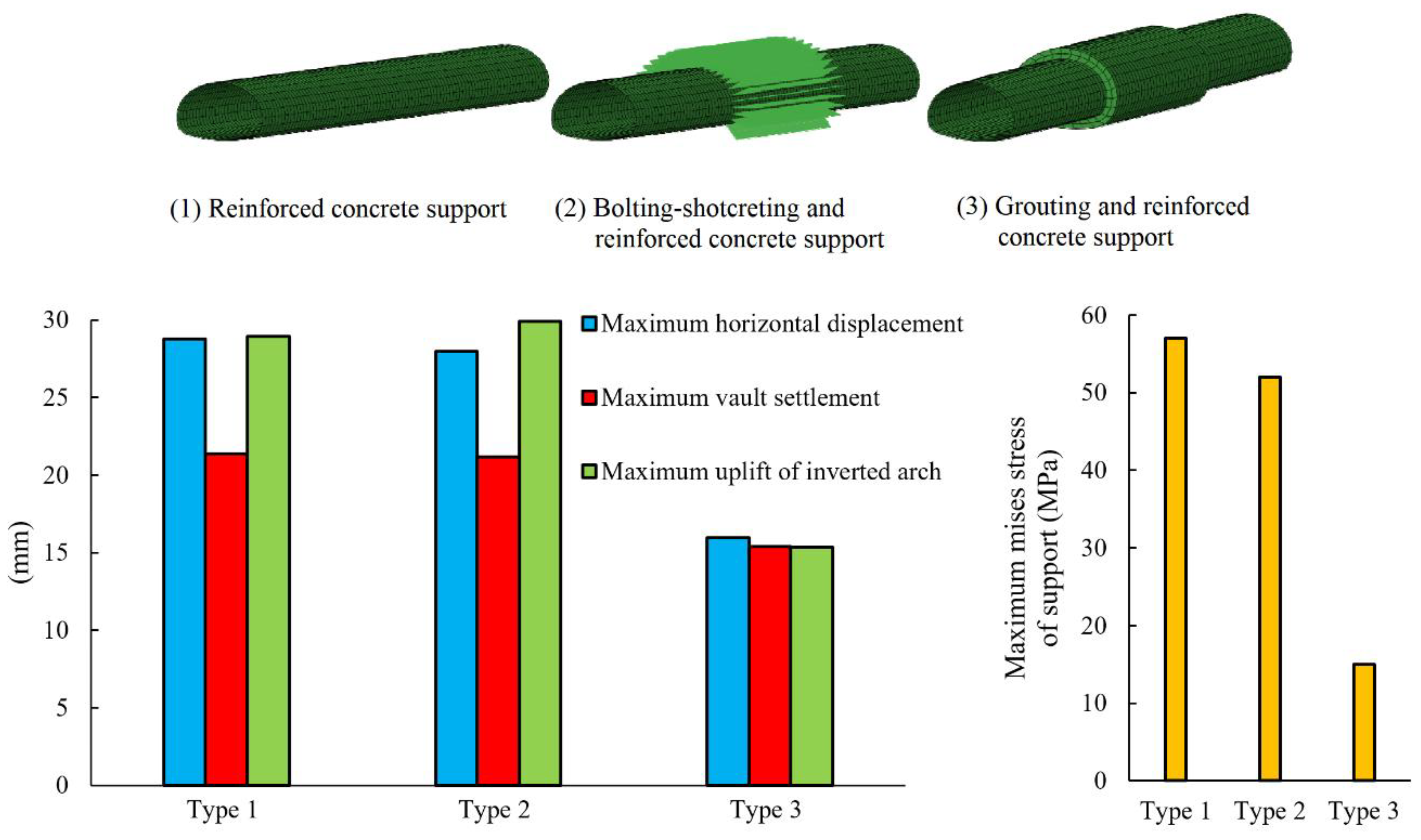
Figure 6.
a) Covering the pipeline trench with a friction-reducing geotextile (Gantes & Bouckovalas, 2013), b) Placing the pipeline within buried concrete culverts (Gantes and Melissianos, 2016), c) Low-density gravel in a pipeline trench (Rojhani et al., 2022), d) Load transfer from Tire derived aggregates to buried pipeline (Sim et al., 2012).
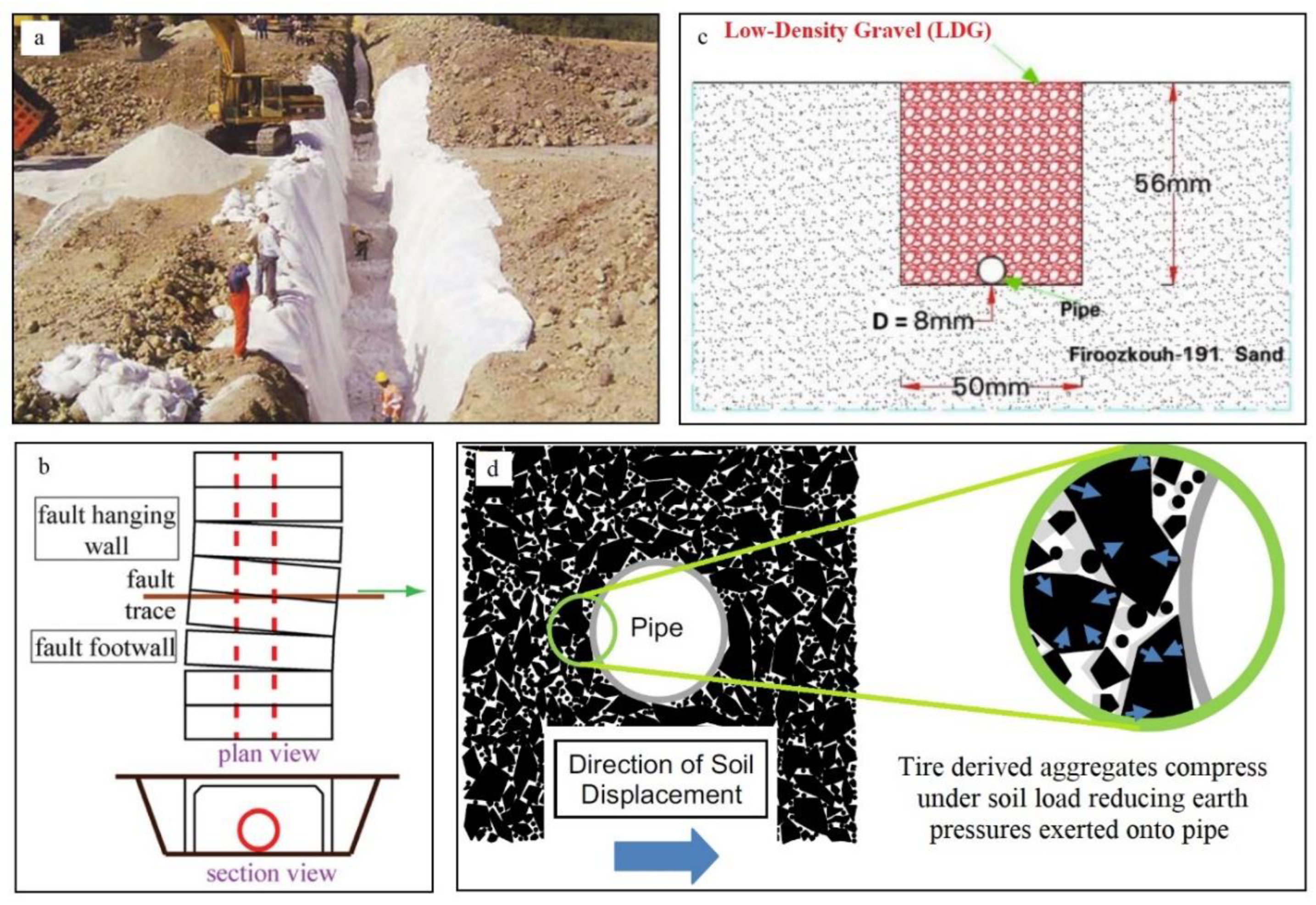
Figure 7.
a) Schematic image of a pipeline protected with geofoam block, b) Pipeline buried in soil with and without geofoam block subjected to strike-slip fault displacement (Rasouli and Fatahi, 2020).
Figure 7.
a) Schematic image of a pipeline protected with geofoam block, b) Pipeline buried in soil with and without geofoam block subjected to strike-slip fault displacement (Rasouli and Fatahi, 2020).
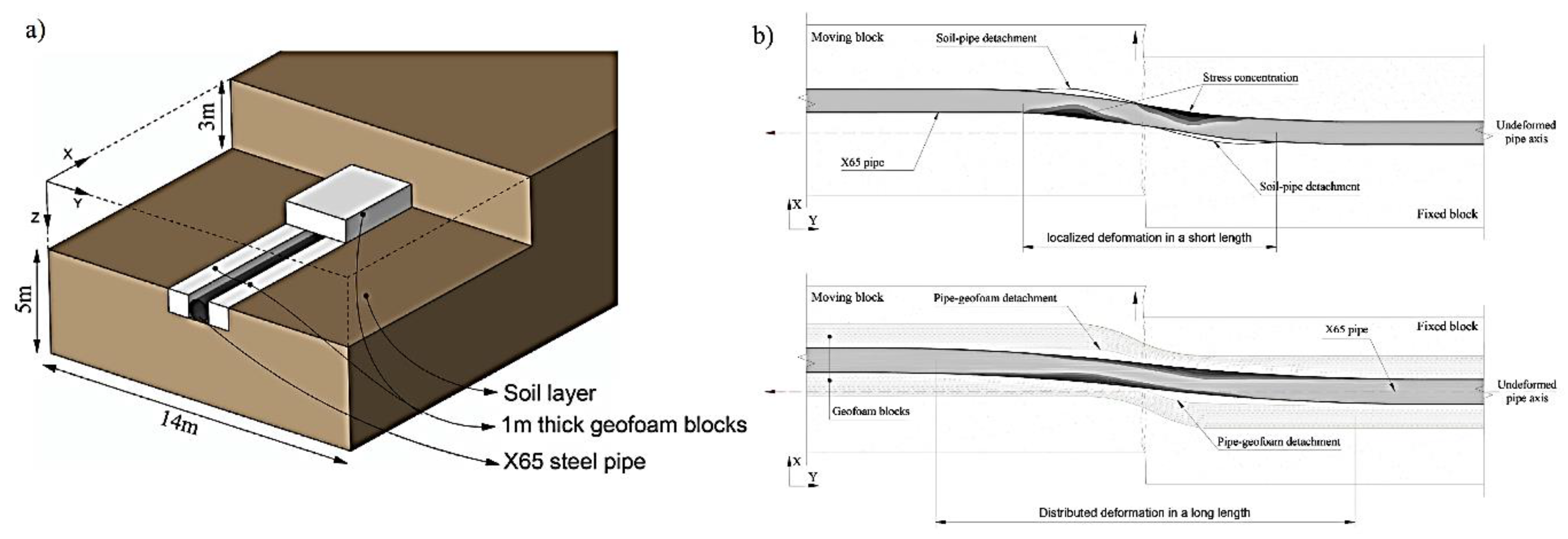
Figure 8.
Displacement contours of models with and without.diaphragm walls (Yao et al., 2020b).
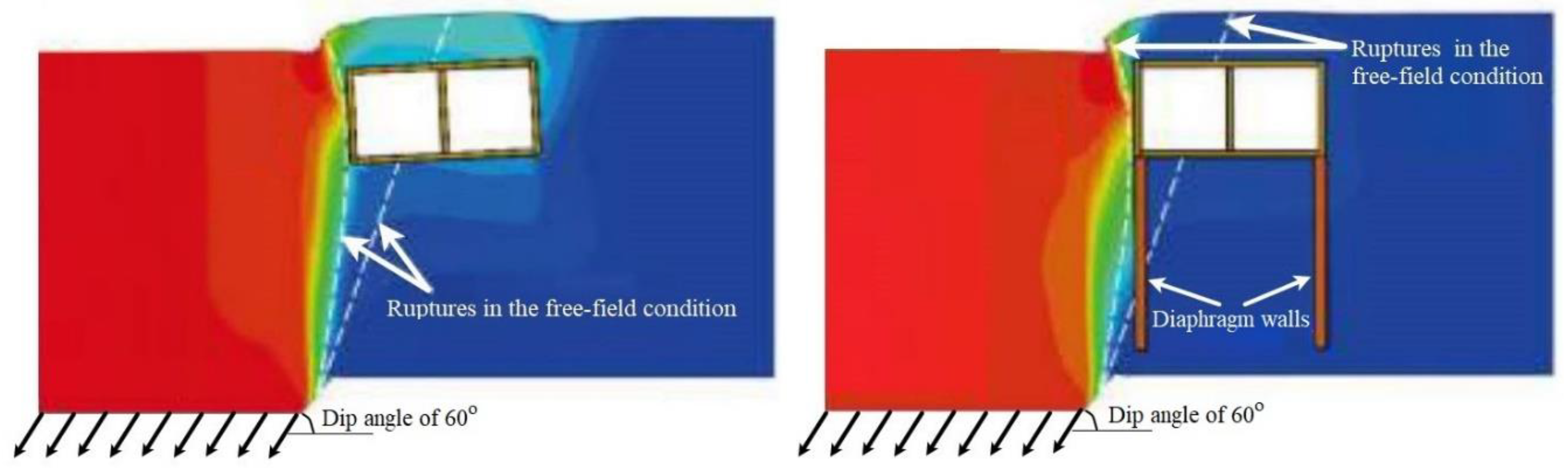
Figure 9.
Possible mechanisms of tunnel-walls-soil interaction: a) hanging wall, (b) shear, and (c) footwall mechanisms (Yao et al., 2023).
Figure 9.
Possible mechanisms of tunnel-walls-soil interaction: a) hanging wall, (b) shear, and (c) footwall mechanisms (Yao et al., 2023).
Disclaimer/Publisher’s Note: The statements, opinions and data contained in all publications are solely those of the individual author(s) and contributor(s) and not of MDPI and/or the editor(s). MDPI and/or the editor(s) disclaim responsibility for any injury to people or property resulting from any ideas, methods, instructions or products referred to in the content. |
© 2024 by the authors. Licensee MDPI, Basel, Switzerland. This article is an open access article distributed under the terms and conditions of the Creative Commons Attribution (CC BY) license (http://creativecommons.org/licenses/by/4.0/).
Copyright: This open access article is published under a Creative Commons CC BY 4.0 license, which permit the free download, distribution, and reuse, provided that the author and preprint are cited in any reuse.


