
Submitted:
26 November 2024
Posted:
27 November 2024
You are already at the latest version
Abstract
Ship hull girder model has been widely adopted in ship mechanics researches such as the small-scale and large-scale hydroelastic ship model experiments. This research proposes a simple and novel ship hull girder design methodology that overcomes some of the main shortcomings of existing methods. The main novelties of this research are (1) the structural rigidity design requirement for the ship hull girder corresponding to any targeted real ship with arbitrary structural complexity is precisely satisfied; (2) the mass density per unit length of the proposed hull girder is exactly only related to the mass density distribution of the targeted ship structures, and thus (3) a better ship hull girder model for prediction of the total structural responses can be consequently established. A real ship is adopted as the design target, the structural responses of the real ship and the proposed ship hull girder model are compared and analyzed. The proposed model is compared to the currently widely accepted ship hull girder models through numerical experiments. The proposed hull girder design methodology possesses potential of upgrading the classical structural design approach to match the growing trend of adopting finite element method(FEM) based approaches for ship structure researches.
Keywords:
ship hull girder
; cross-sectional rigidity
; segmented ship model
1. Introduction
Ship structural safety has been an active research focus ever since the beginning of the era of ship industry of any country around the globe. Structural safety is the prerequisite for the pursuit of outstanding performances of next-gen vessels, such as large container ships [1,2,3] that can carry more containers, and ice-breaking vessels [4,5,6] that are capable of bearing harsh ice conditions, etc. In early times, the estimation methods for ship structural strength are mainly empirical: based on the long-term observations of the characteristics of wave loading on ships and the consequent structural responses, the treatment that the complicated real ship hull can be simplified as a beam is considered to be appropriate, gradually culminating in the establishment of the widely adopted classical method [7,8] for prediction of the total structural strength. The main idea of the classical method is to decompose the total deformation of the ship hull into the so-called global longitudinal deformation and local deformation, in which the global longitudinal deformation is calculated based on the beam theories [9,10], while the local deformation is analyzed based on the plate structure theory [8]. This decomposition methodology makes the seemingly impossible task of reliably predicting total structural responses of complicated real ship hull easily achievable for the ship designers several decades ago when computility was rather weak.
As modern computers prevail in ship industry, ship structural strength estimation has mainly relied on commercial FEM solvers. According to the FEM theories [11,12,13] and the accumulation of empirical experiences of real ship operations, the main classification societies in the world released rules [14,15,16,17,18] for the modeling of ship structures based on FEM theories. Although the released rules contain guidance on full length structural strength analysis based on the global FE modeling of the whole ship structure, hull girder strength estimation methodology still prevails in those rules due to the effectiveness and efficiency of such simplification for most loading conditions. A global FE analysis that covers the whole ship structure may be required for ships with large deck openings subjected to severe oblique sea conditions that cause overall torsional deformation [17]. In addition, the hull girder strength estimation approach is more suitable for preliminary structural design of a new ship. Therefore it is still safe to say that the key idea of the classical method still dominates in many areas of ship structural strength estimation in ship industry, and it can be anticipated that improvement to the classical method may quickly have an impact on ship engineering.
In recent years, researchers have adopted FE modeling method as well as other notable computational mechanics methods to solve the pressing challenges raised in ship mechanics. Zhao et al [19] proposed a computational framework to simulate ship-ice-ridge interactions. The local bow structure of the original icebreaker, modeled by FE elements, were chosen as the sub-structural model for demonstration of their proposed framework. Jiao et al [20] presented a partitioned CFD-FEM two-way coupled numerical tool to investigate asymmetric water entry problems of local bow and stern structures. A wedged grillage structure modeled by FEM represents the local bow or stern structures. Jiao et al [21] adopted a coupled CFD-FEA method to predict slamming and green water loads on a containership sailing in regular waves, where the scale ratio for the numerical standard S175 type containership model was 1:40. The scaled numerical containership was modeled as a hull girder whose vertical bending stiffness was assumed to be constant, and the first order natural frequency of vertical bending vibration for the numerical hull girder satisfied the requirement of the principle of similarity [22]. Hu et al [23] studied ductile fracture of stiffened ship hull plates during ship stranding by using the meshfree Reproducing Kernel Particle Method(RKPM) [24,25], where the stiffened plates were locally extracted from the ship bottom of the global ship hull. Liu et al [26] conducted numerical and experimental investigation on the collision of the hull structure at local stiffened plates. In particular, the real ship collision accident is modeled as inclined penetration of the local stiffened plate extracted from the ship hull. Heo et al [27] adopted Peridynamics to study buckling behavior of local cracked plates of ship hulls. Aiming at investigating the influence of brittle crack growth on the strength of ship structures, Nguyen and Oterkus [28] adopted a peridynamic shell model [29] to simulate brittle crack propagation in an experimental MST4-ship model [30] which now can be viewed as a segment of ship hull near the middle cross-section. The above research efforts reveal that the decomposition approach from the aforementioned classical method still plays a vital role in ship mechanics investigations.
This research is aimed at improving the classical method which may lead to quick impact on ship industry. In contrast to the wide attention payed to the calculation of the local responses at specific ship hull spots, this research carefully studies the methodology of establishing the ship hull girder model for better understanding of the global longitudinal structural responses within the classical method. We found some of the main drawbacks of existing methods, and accordingly proposed a method to model the complicated real ship hull that overcomes those shortcomings. The immediate influence of the proposed method is probably on the scaled hydroelastic ship model experiment technology which heavily relies on the quality of the elastic ship model hull girder. Based on the proposed ship hull girder design methodology, we further upgrade the classical method to more consistently match the trend of adopting FEM for ship structural strength estimation. In addition, we quantitatively analyze the error between the structural responses obtained by the improved classical method and the full three-dimensional FE modeling method, which is also scarce in the literature.
This paper is organized into eight Sections. In Section 2, We present briefly the theory of Euler-Bernoulli beam which is the main theory adopted in the classical method, and then analyze the main shortcomings of the full application of beam theory in ship structural mechanics. The method of establishing the new ship hull girder system that overcomes the aforementioned drawbacks of the existing beam theory is detailed in Section 3, culminating in the upgrade of the classical method which is presented in Section 4. Basic verification of the newly proposed hull girder system design method is detailed in Section 5. Section 6 introduces the necessary establishing details of a full-scale hull girder system based on a targeted real ship, with a comprehensive comparison of the ship structural responses obtained from the real ship FE model and the full-scale hull girder FE model. To further prove the necessity of the proposed design method, in Section 7, the longitudinal global structural responses of two currently widely accepted backbone-type ship hull girder models are compared with those responses calculated by the proposed ship hull girder model. We close the presentation in Section 8 with discussion and conclusion.
2. A Brief Review of Euler-Bernoulli Beam Theory and Its Applications
2.1. The Euler-Bernoulli Beam Theory
The Euler-Bernoulli beam theory has been widely adopted in ship mechanics. This beam theory requires the real ship hull to be slender, so that the ship hull can be formulated as a slender beam without influence of shear force and moment of inertia. The forced vibration equation of a Euler-Bernoulli beam [31] is as follows:
where E is the Young’s modulus which is assumed to be constant along the beam, I(x) is the second moment of area of the cross-section at longitudinal position x of the beam, m(x) is the mass of the beam per unit length, P(x,t) is the dynamic external loading per unit length at time t. Eq. (1) can be fully expanded as follows:
If I(x) is assumed to be constant, then Eq. (1) and Eq. (2) can be simplified as:
If m(x) in Eq. (3) is further assumed to be constant, then based on Eq. (3), the natural vibration frequencies of the beam whose ends are simply-supported can be analytically derived as [31]:
where ωn denotes the n-th order natural vibration frequency, L is the length of the beam. If the second moment of area I(x) or the mass density m(x) is not constant, then the natural vibration frequencies of the beam are very difficult to obtain by analytical approaches, and the transfer-matrix method [32] is widely adopted to numerically calculate the natural vibration frequencies and the corresponding vibrational modes.
2.2. Application in Global Longitudinal Strength Estimation of Ships
One of the applications of the Euler-Bernoulli beam theory was to estimate the global longitudinal strength of real ships. In that application, the real ship hull is simplified as a full-scale Euler-Bernoulli beam. This is achieved not by literally establishing a full-scale beam model that corresponds to the original real ship hull, but by just assuming that the original real ship hull should response to the external loading according to the same mechanism as the Euler-Bernoulli beam does. Then the global longitudinal response of the real ship hull can be immediately obtained by the following simple formula [8] once the cross-sectional vertical bending moment M(x,t) is obtained:
where σ(x,t) is the global normal stress at time t at cross-section x, z is the vertical position of the structural component at the cross-section relative to the neutral axis, I(x) is the second moment of area of the cross-section x. After the acquisition of the global longitudinal structural responses of ships, the total structural response of any structural component of ships is assumed to be the sum of the global longitudinal response and the local response, which is the core of both the classical and modern ship structural analysis methods. Therefore the first application of the Euler-Bernoulli beam theory in ship mechanics can be concluded as laying the foundation for ship structural analysis.
However, shortcomings related to this application of the Euler-Bernoulli beam theory can be found. The treatment that the real ship hull itself is directly thought of as a Euler-Bernoulli beam leads to a problem that, this ship hull beam in fact can not be accordingly literally modeled by a FE modeling software, because if the hull beam were to be built by a FE simulation tool, the beam in question is in fact the whole original real ship hull itself which we do not want to build in the first place. That is, the first application mentioned above does lack a truly full-scale Euler-Bernoulli beam model for the targeted real ship hull, which will be dubbed “independent hull girder” for the corresponding real ship here in this research. This independent hull girder is a beam for its own sake that is related to the targeted real ship, and is not the targeted real ship itself. Seriously speaking, the experimental hydroelastic ship hull girder is in fact designed to test the properties of the independent hull girder mentioned above of the targeted real ship hull, not directly the targeted real ship hull since the local responses are not included in the experimental model. The lack of such an independent hull girder model of the targeted real ship makes the experimental results from the hydroelastic ship model tests become indirect experimental data on the global longitudinal structural responses of the targeted real ship hull.
In shipbuilding industry, the influence of lack of a realistic full-scale Euler-Bernoulli beam model for the real ship is greatly mitigated since the international ship classification societies [14,15,16,17,18] have proposed empirical formulas to directly calculate ship hull girder loads. Thus one of the purposes of this research is to provide a method which can precisely establish a full-scale Euler-Bernoulli beam model for any kind of real ship, serving as a new tool for proposing new empirical formulas for new kinds of ships.
2.3. Application in Design of Scaled Hydroelastic Ship Models
Since the real ship hull itself does not have its corresponding full-scale beam model, or here the so-called independent hull girder model, the design task of a realistic beam model related to the real ship hull is in fact carried out in the scaled segmented hydroelastic ship model experiment. The scaled experimental ship hull girder is designed to meet the principle of similarity concerning cross-sectional rigidity and mass density. The principle of similarity derived from the Euler-Bernoulli beam theory is as follows [22]:
where the subscripts 1 and 2 denote the targeted real ship and the scaled experimental ship model, respectively, with the subscripts s and c respectively denoting the ship structures and the cargo. The subscript G denotes the cross-sectional center of gravity(COG). X and x are respectively the longitudinal coordinates locating the longitudinal positions of cross-sections of the targeted real ship hull and the scaled experimental ship hull girder model. λ is the so-called scaling ratio of the experimental ship model. E denotes the Young’s modulus, I denotes the cross-sectional second moment of area, L denotes the length perpendiculars, m denotes mass per unit length, ZGs1(X) denotes the vertical position of the COG of the cross-section X of the targeted real ship hull, with other similar terms denoting the counterparts for the scaled ship model.
The strict requirements expressed by Eq. (6) are difficult to meet for both the small-scale and large-scale hydroelastic experimental ship models through existing design methods. An alternative design principle was widely adopted as a compromise which is that the first equation of Eq. (6) was changed to the similarity of the first three orders of natural frequencies [33,34,35,36,37,38,39,40,41,42,43], while the second and third equations were changed to the similarity of the positions of the COG of the final overall rigid ship. The advantage for the change of the first equation of Eq. (6) is that the beam theory was changed to the more advanced FE theory if the natural frequencies of both the real ship and the scaled ship model were calculated based on their respective FE models. However, it has been found that by using the current available techniques, it is also very difficult to strictly meet the compromised requirement that all the three orders of natural frequencies were similar. In fact, only the first order natural frequency similarity can be satisfactorily met, thus decreasing the precision of this alternative principle to Eq. (6).
Another shortcoming associated with the aforementioned alternative principle to Eq. (6) is that, it is very difficult to strictly distinguish the masses of the ship structures from the masses of the cargo. In most previous hydroelastic ship models, the length of the hull girder was evidently smaller than the length of the rigid ship shell, thus indicating that there are plenty of cross-sections whose masses of the ship structures were actually totally replaced by non-structural masses. Therefore for ships carrying large tonnage of cargo, such experimental design may bring in uncertain effects on the final experimental results. In addition, this indistinguishability of different mass components of the ship also exists in the application of the Euler-Bernoulli beam theory in global longitudinal strength estimation of ships. In the calculation of the so-called static shear force of ships in still water and the calculation of strong nonlinear wave loads of ships in severe seas by using the Euler-Bernoulli beam model of the real ship, it is inevitable to add the masses of cargo to the masses of the ship structures to finally form the overall masses of the beam model which may cause uncertain influence on the final calculation results. It is evident that the large weight of cargo is a kind of static external loading and plays no role in resisting ship structural deformation, and therefore should be separately considered. However, if the Euler-Bernoulli beam theory is the only tool to model the mass density of real ship hull carrying cargo, the masses of cargo will inevitably be treated as the additional masses to the ship structures that help resist ship structural deformation, which is in direct conflict with the actual function of the masses of cargo.
3. A Novel Hull Girder Design Methodology
This research proposes a novel design methodology for the ship hull girder of its targeted real ship that overcomes the aforementioned shortcomings inherent in the existing methods. This new design approach presents a full-scale FE beam model for its targeted real ship hull which not only can be used to directly analyze the global longitudinal structural responses of the real ship, but also provides direct guidance for design of hydroelastic experimental ship hull girder that strictly satisfies Eq. (6). Further, this new design methodology may bring in a upgrade of the classical ship structural estimation method, making the upgraded method in line with the trend of modern development of computational ship structural mechanics.
3.1. Design of the Sub-Cross-Sections of Ship Hull Girder Components
The proposed new ship hull girder design method adopts the basic treatment that the targeted real ship hull can be modeled as a system of Euler-Bernoulli beams. By setting L1=L2 and λ=1 in Eq. (6), the corresponding design principle for the full-scale ship hull girder of the real ship hull is:
As has been mentioned in Section 2.3, there is a everlasting challenge in the experimental design of the hydroelastic ship hull girder that the similarity of structural rigidity is difficult to be strictly met [33,34,35,36,37,38,39,40,41,42,43]. The cross-sectional rigidity design of a full-scale hull girder of the real ship by the existing methods is more difficult than the design of a scaled hull girder of the same real ship, because for a scaled hull girder, the cross-sectional rigidity is scaled to be much smaller which reduces the difficulty of the design task. This research proposes a simple solution to overcome this everlasting problem, as well as the mass density problem. The proposed new hull girder design approach is both based on the Euler-Bernoulli beam theory and the FE modeling techniques, and takes a two-step strategy to finally strictly meet the design principles for the full-scale hull girder expressed by Eq. (7). The finally obtained full-scale hull girder is in fact a FE model system consisting mainly of deformable hull girders and undeformable segmented outer ship shells, similar to the familiar segmented hydroelastic ship model to some extent. The undeformable segmented outer ship shells are designed as the media upon which the external loading on ship will be applied, and the hull girders consequently deform as the global longitudinal structural responses of the targeted real ship hull due to the application of external loading on shells.
The first step of the new design approach is to meet the mass density requirement expressed by the second and third equations of Eq. (7) whilst distinguishing the masses of the ship structure from masses of the cargo. With reference to Eq. (7), the mass per unit volume ρ2(x) and area A2(x) of the cross-section x of the full-scale ship hull girder are obtained by:
where ρ1i(x) denotes the mass per unit volume of i-th ship structural material on cross-section x of the targeted real ship hull, and N(x) is the number of structural components on cross-section x. Eq. (8) ensures that the newly designed ship hull girder itself purely corresponds to the targeted real ship structures without involvement of the cargo. Then the vertical position of the COG of A2(x), which is ZGs2(x), is required to be equal to ZGs1(x) according to Eq. (7). This requirement will be treated later after the exact geometry of A2(x) is determined.
The second step of the proposed method is to satisfy the cross-sectional rigidity requirement expressed by the first equation in Eq. (7). If the full-scale beam is assumed to be a single rectangular beam, which is exactly how the existing methods assume the beam model to be, then the cross-section x of the beam model in question satisfies the following equations:
where b(x) and h(x) are respectively the width and the height of the cross-section of the single rectangular beam. Eq. (9) is thus in fact a over-determined system for the height h(x). Substitute the first equation into the second equation of Eq. (9) yields:
The first equation of Eq. (10) is not guaranteed to be compatible with the second equation of Eq. (10), which is the central problem for the existing methods. This is caused by the stereotypical assumption that the ship hull girder should always be a single rectangular beam. The proposed new design approach, which is also within the Euler-Bernoulli beam theoretic framework, assumes that the ship hull girder system is allowed to be composed of multiple beams along the vertical direction of the cross-section of the targeted real ship, with the sub-cross-section of each beam component being any of the following common familiar regular shapes: a triangle, a rectangle or a trapezium. For any kind of real ships, this newly proposed hull girder system of multiple beams always exists, which can be qualitatively certified as follows:
Suppose the interior of any cross-section of the real ship is filled with a material whose density is ρ2(x) and elastic modulus E2, then it is guaranteed that the mass density and second moment of area of that filled interior are both larger than those of the materials forming the original boundary domain of the cross-section of the real ship. In other words, the interior always leaves enough room for the design task no matter how complicated the boundary is. Therefore there always exists a combination of aforementioned sub-cross-sections corresponding to the beam components whose combined mass density and second moment of area are equivalent to those of the materials at the boundary of the cross-section forming the original ship cross-section. It is also evident that for any given cross-section from the targeted real ship, there exists more than one design of allowable full-scale ship hull girder system, since the choice of the specific geometries of the beam components is not strictly prescribed. However, the number of disjoint sub-cross-sections corresponding to the beam components should be no bigger than 3, for the sake of the consideration that the effect of local response of the final full-scale hull girder system should be controlled negligible.
For the purpose of illustration, we first present a two-rectangular-beam hull girder system by using the proposed hull girder design methodology. The upper beam is labeled U, while the lower beam is labeled D. The upper beam’s width and height are denoted as wU(x) and hU(x), respectively, while the lower beam’s wD(x) and hD(x). If such a two-rectangular-beam system exists, then it must be determined by the following equations:
where IU0(x) and ID0(x) respectively denote the second moments of area of the cross-sections relative to their own neutral axes for the upper beam U and lower beam D. dU(x) and dD(x) respectively denote the parallel distances between the neutral axis of the whole cross-section and the neutral axes of the upper and lower beam cross-sections. Eq. (11) is thus a under-determined system. One feasible choice to make Eq. (11) yield a unique solution is to add the following three equations:
where β(x), αU(x), αD(x) are coefficients determining the detailed cross-sectional geometry of the two beams. The values of these three coefficients are specified by the users. In general, Eq. (11) and Eq. (12) yield a unique solution of a two-rectangular-beam system as the full-scale ship hull girder for many kinds of targeted real ships. The full-scale hull girder system for bow regions of many kinds of real ships may not be successfully designed through this two-rectangular-beam model since the complicated geometry of the interior domain of such cross-sections may not be satisfactorily approximated just by rectangles. In case of encountering such type of real ship cross-sections, a composite sub-cross-sections of different shapes will solve the problem, thus complementing the simpler two-rectangular-beam system to finally establish the total full-scale ship hull girder system for any kind of targeted real ships.
A general composite hull girder system design can be obtained by generalizing the previously introduced design of a two-rectangular-beam system. For the purpose of generality, suppose a cross-section extracted from the bow region of a real ship whose shape is a smooth combination of a triangle and a bulb. The bottle-neck shaped smooth transition region is further supposed to be quite narrow. The geometrical characteristics of this chosen cross-section is quite representative in bow region for ships with pronounced bulbous bow structure. Similar to the meshing art in FEM, the upper single beam Ω is assumed to be an isosceles trapezoidal beam while the lower beams a double-isosceles-trapezoidal beam system which should guarantee a satisfactory hull girder cross-section modeling of the chosen real ship overall cross-section. The upper and lower isosceles trapeziums of the lower beams system are respectively denoted as B and C. The distances between the top side of the overall cross-section and the upper and lower parallel sides of Ω are respectively denoted as dΩu and dΩl, where the subscripts u and l respectively denote the upper and lower parallel sides. The distances between the bottom base line of the overall cross-section and the upper and lower parallel sides of B are respectively denoted as dBu and dBl, with the corresponding distances for C being denoted as dCu and dCl. Then the design principles are precisely expressed by the following equations:
where symbol A denotes the area, symbol z denotes the vertical position of neutral axis, symbol I denotes the second moment of area, symbol T denotes the parallel distances between the neutral axis of the overall cross-section of the real ship and the neutral axis of the sub-cross-section of a beam component. Subscript 0 denotes the reference to the neutral axis of the sub-cross-section of a beam component. Then the meaning of any term in Eq. (13) can be directly and easily derived by the readers, for example, the composite symbol AΩ denotes the cross-sectional area of beam Ω. To make Eq. (13) yield a unique solution, first the following complementary equations should be added:
which in fact just explicitly expresses every term in Eq. (13) for the chosen shapes of the beam components. The composite symbol hΩe denotes the vertical distance of the COG of beam Ω to its own upper parallel side, while hBe the vertical distance for beam B and hCe the vertical distance for beam C. H denotes the overall height of the overall cross-section, which is a known parameter. Symbol W in Eq. (14) denotes length of any parallel side of any trapezium. Then the meaning of any term in Eq.(14) can accordingly be directly derived by the readers, for example, WΩu and WΩl respectively denote the lengths of the upper and lower parallel sides of beam Ω. The following constraint equations are needed to close Eq. (13) and Eq. (14):
where R denotes the length of the uppermost base of the overall cross-section, with θ denotes the angle between the uppermost base and its neighboring leg. R and θ are thus the known parameters of the overall cross-section. Symbol α denotes the angle between the leg and the longer parallel side of an isosceles trapezoidal beam component. αΩ, αB and αC are thus also the known parameters of those isosceles trapeziums adjusted by the users during the design or solution procedures. The length of each W-symbol associated quantity in Eq. (15) is then prescribed by its local largest width of the overall cross-section, denoted by each Q-symbol associated quantity which is known a priori, to ensure that the finally obtained beam system is positioned totally within the geometrical boundary of the overall cross-section. It is evident that, by uniting Eqs. (13), (14) and (15), a unique design of the composite beams system can be achieved which precisely meets the design principles expressed by Eq. (7).
The united Eqs. (13), (14) and (15) are recommended to be solved by the trial and error method instead of analytically finding its solution. This is due to the first six inequalities in Eq. (15), each of which in fact just describes the general characteristics of its corresponding W-symbol quantity. In other words, the united Eqs. (13), (14) and (15) only effectively assert that there exists at least one solution of the hull girder system in question, but the specific solution is allowed to be user-dependent. The trial and error method to solve the united Eqs. (13), (14) and (15) thus endows freedom to users that those six inequalities can be flexibly applied to deal with every possibly encountered overall cross-section. Once the W-symbol quantities, together with the correspondingly determined d-symbol quantities, are found to simultaneously satisfy other equations of the united equations, the expected solution of the sub-cross-sections corresponding to the beam components is finally obtained.
Note that, even for the simpler two-rectangular-beam case expressed by Eqs. (11) and (12), the trial and error procedure is also necessary because the users have to try different parameters of αU, αD, and β to find the two-rectangular-beam solution. The two-rectangular-beam case is simpler because once the three basic parameters are appropriately chosen, dU and dD can be analytically solved based on Eqs. (11) and (12). Thus, by uniting the techniques of designing a two-rectangular-beam model and a general complicated composite beams model, a complete full-scale ship hull girder system for any kind of targeted real ships can be obtained which not only solves the problem that such a full-scale ship hull girder is currently absent for the real ship, but also serves as a solution to the everlasting difficulty of designing a hull girder strictly satisfying the principles of similarity for scaled hydroelastic ship models.
It is further found that, both the two-rectangular-beam and the composite beam cases introduced above can be seen as two examples in a general ship hull girder design framework, whose main design procedures are: (1) to present the expressions of the structural requirements, followed by (2) expressions interpreting each term in the first procedure, and ends by (3) the supplement of geometrical constraints. The first procedure is the design requirements as can be materialized by Eq. (11) and Eq. (13) as examples. This first procedure does not require determination of specific geometrical characteristics of the sub-cross-sections of the targeted hull girders. The second procedure provides detailed expressions explaining every term in the first procedure, requiring the choice of the shapes of the sub-cross-sections of the targeted hull girders, as can be materialized by Eq. (14) if the shape is chosen as a trapezium. The contents of the last procedure on the one hand reveal the intrinsic relations between the basic geometrical parameters of the chosen shapes, such as the last three equations in Eq. (15) which just describe the basic geometrical relationship between the legs and parallel sides of a trapezium, and on the other hand point out that the geometrical boundaries of the targeted hull girders must be within the geometrical boundary of the ship cross-section, such as those inequalities in Eq. (15). Note that the deck is not included in the boundary of the original ship cross-section, implying that the resultant beam component is allowed to extend outside the upper deck, as will be shown in later contents of this research. The generalized design framework thus endows the maximum freedom to the designers to establish appropriate ship hull girder system.
3.2. Formulation of a Calculable Ship Hull Girder FE Model
This sub-section continues to show how to complement the new ship hull girder system with the outer ship shell to finally form a complete FE model capable of predicting global longitudinal structural responses of the targeted real ship. Each hull beam component is modeled by a collection of three-dimensional hexahedral meshes. The whole outer ship shell is modeled as a rigid shell based on the table of offsets of the targeted real ship. The mass of the whole rigid ship shell is set to be extremely small so that it will exert negligible effect on the mass distribution of the final complete FE model. The original intact rigid ship shell is then divided into several disjoint segments by removing a number of slim slices which are evenly distributed along the longitudinal direction of the whole rigid ship shell. Within each ship shell segment, the narrow middle regions of each beam component are rigidly fixed by several massless rigid supports stretching out from the same narrow middle area of the rigid ship shell segment. The rigid ship shell segments are designed to directly withstand the distributive dynamic wave loading pressures from the surrounding fluid, and the rigid supports will transmit the exterior wave pressures to the whole of the beam components through the beam fixing regions. The number of the segmented rigid ship shells and the size of the fixing middle region of the beams need to be determined appropriately, and the previous design of the scaled hydroelastic experimental segmented ship models may provide relevant reference [33,34,35,36,37,38,39,40,41,42,43].
Now it comes to the treatment of cargo masses included both in Eq. (6) and Eq. (7). The original real ship cargo holds will be modeled as nearly massless rigid model cargo holds which are then placed within the established FE model just as where the original cargo holds are actually located in the targeted real ship. The original cargo masses that are distributed in the original cargo holds are equivalently modeled as distributive static loading on the bottom areas of the modeled rigid cargo holds. This treatment not only recovers the function of cargo masses on the ship structures but preserves the original spatial distributive characteristics of those cargo masses in the targeted real ship. Therefore it can be anticipated that during the design stage of a new ship, the influence of cargo masses distribution on the final ship structural responses can now be directly studied by using the proposed new ship hull girder model. This is an evident advantage of the proposed methodology over the existing beam design method, since the existing method can not even distinguish the masses of the ship structures from those of the cargo.
4. A Upgrade to the Classical Structural Strength Estimation Method
The classical ship structural strength estimation method decomposes the total deformation of a structural component into the global longitudinal deformation and the local deformation. The global longitudinal deformation is calculated based on the beam theories which additionally assume that every cross-section of the beam remains flat throughout the deformation duration, a concept called flat cross-section assumption [8] which lays the foundation for classical ship structure mechanics. In fact the flat cross-section assumption is not an indispensable ingredient in the classical ship structural strength estimation method, because the key idea is to decompose the total deformation of a structural component whilst ensuring that the computational models for the global longitudinal deformation calculation and local deformation calculation should be directly related to the original targeted ship. A hull girder system whose cross-sectional rigidity and mass density are equivalent to those of the original targeted ship is sufficient to serve as the computational model for calculation of the global longitudinal deformation. The flat cross-section assumption based beam theories in fact exert extra restrictions on the characteristics of shear force on the cross-sections that the shear stresses must be constant along every cross-section. The proposed new ship hull girder is modeled by the three-dimensional hexahedral elements which will not be prescribed by the flat cross-section assumption, thus broadening the application of the decomposition methodology. Thus the classical structural strength estimation method can now be upgraded by the proposed ship hull girder model as follows:
For ships sailing in head seas, the total deformation of any structural component can be decomposed into the so-called global longitudinal deformation and the local deformation. The global deformation can be calculated based on a composite ship hull girder model which is free from the problems associated with the classical Euler-Bernoulli beam model, while the local deformation can be calculated based on the local FE model of the local real ship hull structure.
This newly upgraded version of the classical ship structural strength estimation method can be anticipated to serve as a new additional tool for design of ship structures, along with the available empirical formulas presented in the rules and guidance released from international ship classification societies.
5. Verification of the Proposed Beam Cross-Section Design Method
An overall cross-section containing a bulbous region was extracted from a 64000DWT bulk carrier, and the proposed ship hull girder cross-section design method was applied to the chosen overall cross-section to testify its effectiveness. The structural details of the chosen cross-section are shown in Figure 1(a), with the main parameters being presented in Table 1. Applying Eqs. (13), (14) and (15) to this overall cross-section by the trial and error method, a relatively simple solution is obtained, with the main parameters of the beam cross-sections being listed in Table 2. The obtained beam sub-cross-sections are two identical isosceles trapeziums. The existence of the trapezoidal beam sub-cross-sections thus verifies the effectiveness of the proposed beam cross-section design methodology. We also try to apply Eqs. (11) and (12) to this overall cross-section by the analytic approach, and it is found that for this chosen overall cross-section, a two-rectangular-beam solution also exists with the obtained rectangular beams being identical, and we list their main parameters in Table 3. The existence of such a two-rectangular-beam solution thus implies the wide application potential of Eqs. (11) and (12) in bow region cross-sections of real ships.
6. Application of the Proposed Method to a Real Ship
To further comprehensively testify the applicability of the proposed ship hull girder design method, a real ship was chosen as the target for the design of its full-scale ship hull girder system which is required to precisely satisfy Eq. (7). The chosen real ship does not possess a bulbous structure in its bow region, thus the design principles of Eqs. (11) and (12) should be enough to formulate its hull girder system. Although the bow region of the real ship does not contain a bulbous structure, the narrow triangular shape of those bow area cross-sections will pose relatively comparative design difficulty and therefore the requirement of generality for choosing such a real ship is preserved.
It is noted here that, a scaled ship model is not adopted in this research for the following two reasons: (1) as explained in previous Section 3.1, the design task of a full-scale ship hull girder for a real ship is more difficult than the design task of a scaled ship hull girder. This can be inferred from the fact that currently there is no guidance available either from the ship classification societies or the literature on how to establish an independent realistic Euler-Bernoulli beam model for any kind of real ship. In contrast, the scaled hydroelastic ship hull girder model has been widely adopted to perform hydroelastic experiments [33,34,35,36,37,38,39,40,41]; (2) By adopting a real ship, a totally numerical research is possible and a tank experiment can be safely avoided from economic consideration. The total FE model of the real ship in this research can be acquired by request from readers for reproducibility purpose.
6.1. Formulation of the Full-Scale Ship Hull Girder System
The main particulars of the targeted real ship are shown in Table 4, while the main material properties of ship structures are presented in Table 5. The body plan of the targeted real ship is illustrated in Figure 2. The two-rectangular-beam cross-section design methodology of Eqs. (11) and (12) is adopted to perform the construction of a full-scale ship hull girder system for the targeted real ship. The mass densities per unit length and cross-sectional second moments of area of the real ship and its full-scale ship hull girder system are respectively presented in Figure 3(a) and Figure 3(b) for the purpose of comparison. It is found from Figure 3 that, the proposed design method successfully presents a full-scale ship hull girder system whose overall length is exactly the same as the overall length of the targeted real ship, with the mass densities and second moments of area of the chosen cross-sections respectively being identical to those of the targeted real ship. In addition, as illustrated in Figure 4(a), the obtained full-scale ship hull girder system are hull girders with variational cross-sections throughout the ship. To the best knowledge of the authors, this kind of full-scale ship hull girder has never been realized in the literature. This example thus verifies the applicability of the proposed ship hull girder system design methodology.
Figure 4 presents the procedures from the bare beams to finally obtain a complete FE model for the full-scale ship hull girder system to which the realistic three-dimensional wave loading can be applied. An appropriate number of fixing brackets rigidly connecting the outer segmented ship shells to their spatially corresponding ship hull beam components are adopted to form the final FE model as shown in Figure 4(b) and Figure 4(c). As demonstrated in Figure 4(c), the number of segmented ship shells is here set to be 10 as an example, thus 9 cross-sections which are labeled from s1 to s9 from bow to stern are ready to serve as the targets for detailed study on the structural responses.
6.2. Analysis on Effects of Cargo Modeling Methods
The Euler-Bernoulli beam approach to establishing the ship hull girder can not distinguish ship structural masses from cargo masses. This sub-section utilizes the targeted real ship to quantitatively analyze effects of different cargo modeling methods on the final ship hull girder structural responses. For simplicity and without loss of generality, the three segments containing cross-sections s4 and s5 within the parallel middle body of the targeted real ship are picked out to perform the analysis, and two full-scale hull girder segment models are established based on the newly proposed design method. The mass density per unit length for any arbitrary cross-section of the first hull girder model is designed to be the sum of the mass densities of the ship cross-section structures and the cargo, while the second hull girder model is designed totally based on the ship structures with the cargo weight being modeled as a static loading, as shown in Figure 5. The cross-sectional rigidity of the first hull girder model is kept the same as that of the second. The pure weight of the ship structures of the chosen part is 1217.71t, and the weight of the cargo is designed to be 4083.29t. The cargo mass is designed to be over three times larger than the ship structural mass for the consideration of possible large cargo loading conditions. Figure 6 presented the final FE models for the two full-scale hull girder segments. Note that the second hull girder segment is just extracted from the whole of the full-scale ship hull girder model which has been introduced in the previous sub-section. We further specify that the cargo is loaded on the inner bottom plates along the three segments, and therefore in the second hull girder FE model, the rigid inner bottom plates on which the static cargo loading is applied are built, as demonstrated in Figure 6(b). The basic physical parameters of the first hull girder segment are listed in Table 6.
The wave loads on the two FE models are chosen to be the transient bottom slamming loads. The applied transient bottom slamming loads are calculated based on an empirical formula in [44] (in Section 5 of Chapter 4, Section 1 of Volume 9):
where coefficients fSL and cSL-et are determined based on their corresponding empirical formulas presented in [44] which we omitted for brevity. The loading duration is set to be 0.93s. The structural responses of the two FE models under the applied transient bottom slamming loads are calculated by a recent version of ABAQUS software, and the peak vertical bending moments(VBMs) and peak vertical shear forces(VSFs) acting on s4 and s5 are extracted out from the two FE models for comparison as presented in Table 7. The two different FE models lead to evidently different peak values of VBM and VSF on the same cross-section, due to the familiar common fact in FEM that different FE models under the same applied loading must result in different structural responses. This example thus implies the significance of the proposed ship hull girder design methodology.
6.3. Comparison of Structural Responses
This sub-section systematically compares the VBMs and longitudinal total bending stresses of the established hull girder system FE model and its corresponding targeted real ship FE model under a deliberately designed empirical regular wave loading condition. The aforementioned longitudinal bending stress is the normal stress component σ11 whose direction of unit normal vector is parallel to the longitudinal direction of the ship. The targeted real ship FE model is built under the instructions presented in [44], as illustrated in Figure 7. Both the real ship FE model and the proposed ship hull girder FE model are assumed to withstand an empirical regular wave whose loading characteristics are designed as follows: based on [44](in Section 5 of Chapter 4, Section 1 of Volume 9), the total wave loading pressure Pex is the sum of the static water pressure PS and dynamic periodic wave pressure PW, where empirical formulas are presented for determining each pressure component and we do not present the formulas here for brevity. We further assume that the wet surface of the ship is its mean wet surface, and the wave length is equal to the length of the water line of the ship. To capture the dynamic characteristics of wave loading without loss of simplicity and generality, the initial phase distribution of the dynamic periodic wave pressure along the longitudinal direction of the ship is illustrated in Figure 8: the red stepping zone represents negative initial phases while the cyan stepping zone represents positive initial phases, and the magnitude of each stepping column denotes the uniform magnitudes of the initial phases of those dynamic wave pressures within that stepping column. Then the progressive dynamic wave pressures PW(x,y,z,t)=PW|(x,y,z)cos(ωt+ε) along the longitudinal direction of the ship can be established(where PW|(x,y,z) is the pressure amplitude at location (x,y,z), ω is the circular frequency equal to that of the designed regular wave, ε is the designed initial phase as illustrated in Figure 8.). This deliberately designed wave loading thus can be seen as the Froude-Krylov-type loading which appropriately considers the effect of the radiation loading and the diffraction loading [45,46,47] since the empirical formula [44] expressing the amplitude of the dynamic wave pressure involves all the corresponding practical requirements necessary. The numerical simulation is carried out by using a recent version of ABAQUS software, and the structural responses of the two FE models under several wave periodical loading periods are calculated. The relatively stationary structural responses under two sequential wave periodical loading are picked out for comparison.
Figure 9 presents the comparison of cross-sectional VBM between the hull girder FE model and its targeted real ship FE model. VBM plays a vital role especially in hydroelastic segmented ship model experiment. For both existing and this newly proposed ship hull girder models, VBM is the only physical quantity that can be directly compared with the corresponding targeted real ship. Figure 9 reveals that, for the chosen targeted real ship, the cross-sectional VBMs of most sections near the middle of the ship can be approximated by the newly proposed ship hull girder model. Namely, cross-sections from s3 to s6 see rather acceptable agreement of VBMs obtained from the real ship and ship hull girder FE models, with the smallest and biggest relative errors for VBM extreme values being respectively less then 3% and around 20%. For cross-sections s2 and s7, the VBM troughs obtained by the two models agree pretty well, with the VBM peaks differ evidently. Cross-sections s1, s8 and s9 see pretty large differences of VBM peaks and troughs, especially for the cross-section s9 where the biggest relative error for VBM extreme value exceeds 100%. This means that for the chosen targeted real ship under middle sea state, the newly proposed ship hull girder FE model fails to generate reliable VBM predictions for the bow and stern regions. This finding thus warns the current wide application of the ship hull girder model for prediction of targeted real ship VBM in bow and stern regions in cases where the local structural responses in those two regions are considered relatively insignificant.
Figure 12 mainly focuses on comparing the total stress responses obtained directly from the real ship FE model and indirectly through the newly proposed ship hull girder system FE model. For the proposed ship hull girder FE model, the total stress response for the given structural component is the sum of the longitudinal beam bending stress calculated from the VBM obtained by the hull girder FE model and the local stress obtained by the local real ship structural FE model extracted from the whole real ship FE model. As an example, Figure 10 illustrates the local real ship structural FE model for the calculation of total stress in cross-section s5, which is extracted from the whole of the real ship FE model whose geometrical center is the cross-section s5 and whose length is exactly equal to the length of each ship segment. Now the total stresses obtained based on the proposed ship hull girder FE model should be credited as the total stresses obtained by the updated ship structural strength estimation method. Figure 12 also presents the pure beam stress responses obtained through the proposed ship hull girder FE model. Two locations on each cross-section of the ship are chosen as the targets for comparison of stress results obtained by the two models: one location is on the deck plate while the other location is on the bottom plate as illustrated in Figure 11. In general, Figure 12 shows that, (i) the precision of the total stresses from the updated ship structural strength estimation method differs not only from cross-section to cross-section, but also from location to location; and (ii) the beam stress component takes the predominant weight in the total stress. In specific, cross-sections s2, s3, s4, s5, s6 and s8 see only one structural location whose total stresses calculated by the two different models agree satisfactorily, while s7 which is adjacent to both s6 and s8 in contrast sees larger relative errors for most extreme total stresses for both locations. The deck location shows better agreement of extreme total stresses than the bottom location for s4, s5 and s6, while the contrary phenomenon can be found for s2 and s8. The case for cross-section s3 is more complicated that, the deck location sees better agreement for the troughs of the total stresses than the peaks, while the bottom location sees exactly the contrary phenomenon. The results of the pure beam stress component in Figure 12 show that, the local stress component can be seen as minor modification to the pure beam stress component. Among all the locations, only the bottom plate location in cross-section s1 sees its local stress component whose contribution to the total stress is evident. This shows that the hydroelastic ship model experiment is indeed a reliable research approach to obtaining total stress within the framework of the existing and updated ship structural strength estimation method. Some pronounced discrepancies of the total stresses, such as the total stresses of the bottom locations in s4 and s5, reflect the shortcoming of the full application of the flat cross-section assumption in every ship structural component. By comparing Figure 9(d) with Figure 12(h), and Figure 9(e) with Figure 12(j), it is evident that the vertical stress distributions along s4 and s5 are not totally linear as predicted by the flat cross-section assumption, and the two bottom locations therein are the exceptions. In other words, the three-dimensional effect inevitably exists in some locations of the real ship. The bow and the stern regions saw pronounced discrepancy of total stresses simulated by the two models, implying that the updated ship structural strength estimation method fails in bow and stern regions. This fact, similar to the previous VBM case in this sub-section, warns the current wide application of the classical ship structural strength estimation methodology in bow and stern regions. Figure 12 thus implies that, the classical ship structural strength estimation method needs to be further complemented with a deliberate modification strategy to provide satisfactory total structural responses predictions, especially at the bow and stern regions. The proposal of plausible modification strategies is temporarily outside the scope of this research. The newly proposed ship hull girder FE model for the first time quantifies the precision of the classical ship structural strength estimation method, thus paving way for further enhancement strategies.
7. Comparison of the Proposed Method and Current Popular Method
The necessity of the proposed ship hull girder design method may be doubted due to the fact that in ship industry and ocean engineering applications, the design of both the full-scale ship structures and scaled experimental hydroelastic ship models does not seem to be a problem. Take the design task of scaled experimental hydroelastic ship models as an example, practical codes and fast-running computing algorithms based on the aforementioned transfer matrix method have been widely adopted. In addition, the designer can also design the usual scaled ship hull girder by using the commercial FEM software. So it is fair to question the necessity of the efforts to propose new methods to obtain the full-scale or scaled ship hull girder. This sub-Section tries to prove the necessity of the proposed ship hull girder design method, through comparing the proposed design method with the current existing design method.
We take the same real ship in previous Sections as the target ship based on which several full-scale ship hull girders are designed. The first full-scale ship hull girder is designed to be the single rectangular beam with uniform cross-sections, while the second full-scale hull girder takes the form of a single rectangular beam with non-uniform cross-sections. These two kinds of ship hull girders predominates in previous scaled ship hydroelastic experiments [21,37,39,40,42]. Since this research directly focuses on the full-scale ships, the above two hull girder models are therefore designed to be full-scale. Thus these two full-scale hull girder models can be seen as the full-scale counterparts for their corresponding in-door tank experimental hull girder models. These two kinds of ship hull girders belong to the widely adopted category of backbone-type ship hull girders. Compared with the full-elastic ship model, the backbone-type ship model is much easier to be designed and manufactured. As has been discussed in Section 2.3, the backbone-type ship model does not necessarily need to satisfy the strict structural design principle described by Eq. (6) or Eq. (7), and its design efforts center on the following parameters: the natural frequencies, the position of COG, and the moment of inertia. Thus both the uniform and non-uniform backbones can serve as the candidates of the expected ship model hull girder. One important property of both the uniform and non-uniform backbones is that, the length of the backbone can be adjusted to match the overall arrangement of the whole ship model. For example, for the self-propelled hydroelastic experimental ship models, the large stern area of the ship model does not contain the backbone for the sake of arranging the propelling system [39,40,42]. In this Section, the length of the uniform backbone is designed to be half the total length of the targeted real ship, while the length of the non-uniform backbone is designed to be over 0.6 the total length of the real ship, as shown in Figure 13(c) and Figure 13(f). Note that, theoretically speaking, the backbone-type ship model is a partial elastic model because such model is composed of elastic backbone and several rigid ship shell segments. When such ship model vibrates under dynamic wave loading, its response is partially elastic and partially rigid: the backbone as a whole vibrates elastically, while the rigid ship shell segment which does not contain the backbone rotates rigidly. In other words, the structural vibration details of such backbone-type ship models are different from their targeted real ships. In the following contents, the effect of this difference will be manifested.
It is mentioned here that, compared with the proposed design method, adopting the classical design method to obtain the two backbone ship models is not satisfactorily time efficient. The classical design task can be seen as an optimization task with three goals relating respectively to (i) the natural frequency, (ii) the position of COG and (iii) the moment of inertia, with these three goals being dependent on each other. In contrast, the design procedures for the proposed method are clear and straightforward, with the only design freedom being the free choice of the shape of the cross-sections. Note that, the non-uniform backbone here is designed with an extra requirement as follows:
In Eq. (17), I’n denotes the second moment of area for the n-th cross-section of the non-uniform backbone ship model, where n ranges from 1 to 6 corresponding to each interval between two adjacent rigid ship shell segments as shown in Figure 13(d). In denotes the corresponding cross-sectional second moment of area for the targeted real ship. Eq. (17) thus enables that, the longitudinal distribution characteristics of cross-sectional rigidity of the non-uniform backbone are similar to that of the targeted real ship.
The main parameters for the two backbone-type ship models are listed in Table 8. The first order natural frequencies for the two backbone models are designed to satisfactorily meet the first order natural frequency of the targeted real ship, with the relative error for the uniform backbone model being 4.1% and the non-uniform backbone model 2.7%. The second order natural frequencies for the two backbone models are also found to be very close to those of the real ship, the relative errors respectively being 2.6% and 6.5%. The relative errors for moments of inertia of the two backbone models are not bigger than 3.0%. The relative errors for the position of COG of the two backbone models are controlled within 5%. Therefore according to the classical design principles, the two backbone models can be used to predict the VBM responses for the targeted real ship. For clarity, the two backbone-type hull girders and ship models are illustrated in Figure 13. The vibrational modes for both the ship models and the targeted real ship are illustrated in Figure 14.
It is mentioned here that the main parameters for the ship model designed by the proposed method are not presented in Table 8, and the corresponding vibrational modes are also not illustrated in Figure 14. The reason is explained as follows: (i) the FEM based numerical method can not be adopted to obtain the vibrational characteristics for the present proposed ship model whose hull girder system is composed of vertically separated beams, because the vibrational characteristics obtained are for the local beam instead of the beams system as a whole; (ii) if the transfer matrix method based practical codes are adopted, then the obtained vibrational characteristics for the present proposed ship model will be exactly the same as the targeted real ship since the cross-sectional characteristics of the present proposed ship model are exactly the same as those of the targeted real ship. So here in Table 8 and Figure 14, only the two backbone-type ship models are involved in demonstration.
It is also noted here that, the effect of the added mass of water on the vibrational characteristics of the ships is not considered here due to the following reasons: (1) the calculation of the vibrational properties considering the added mass of water is necessary in scaled hydroelastic segmented ship model experiment, since it is much more convenient to verify the ship model vibrational characteristics in water; (2) As has been explained in the preface of Section 6, this research totally focuses on the full-scale ship hull girder model, and the FE analysis to focus on the so-called dry vibrational modes without the consideration of the effect of the added mass of water is sufficient. In addition, the dry vibrational modes have been widely adopted in theoretical hydroelastic analysis method, such as the theoretical method presented in [48].
As can be seen in Figure 14(f), the second order vertical global vibrational mode of the targeted real ship contains evident local vibrational modes located at some regions in the upper deck. The real ship is composed of many adjacently linked plate structures, if the natural frequency of the second order vertical global vibrational mode is close to the natural frequencies of some local structures within the real ship, the local and global vertical bending modes will appear simultaneously. This is also the reason why the vibrational characteristics of the present proposed vertically separate beams system should not be calculated by the commercial FEM software, since only the vibrational characteristics of each separate beam can be obtained. In addition, it is difficult to find the third order global vertical vibrational mode of the targeted real ship since the local vibrational mode dominates at such high frequency. Therefore only the first two orders of vibrational characteristics of the targeted real ship are extracted to serve as the design targets for the two backbone-type ship models.
The VBMs at cross-sections s2 to s6 calculated by different full-scale ship hull girder models under the same external wave loads introduced in previous Section are simultaneously compared to the results obtained from the targeted real ship, as illustrated in Figure 15. The present hull girder system is denoted as the new beam in Figure 15, and it is evident that the present hull girder system provides the most satisfactory VBM calculation results, although evident deviations from the VBM results of the targeted real ship can also be found for the present ship hull girder model. From cross-section s3 onwards, the two backbone models both generate dynamic VBM responses whose phases are evidently different from those for the dynamic VBM responses of the targeted real ship. This phase difference of the backbone model and the targeted real ship is rooted in the fundamental structural characteristics of such backbone models: such backbone models whose length of the backbone is evidently smaller than the total length of the ship model will generate vibration evidently different from their targeted real ships, because the structures along the whole length of the targeted real ship are totally elastic while in contrast the presented two backbone-type ship models are in fact only partially elastic. The present newly proposed design method generates a ship hull girder system whose length is the same as its targeted real ship, thus making the whole ship model totally elastic. Here the meaning of the present ship model being totally elastic should be interpreted as follows: there is no pure rigid body rotation along the length of the newly proposed ship model.
It should be mentioned here that, all the full-scale ship hull girder models adopted in this Section are established in the simplest possible manner without any practical modification such as exquisite arrangement of mass distribution. The purpose of Figure 15 thus is not to challenge the currently widely accepted whole design procedures for the two widely accepted backbone-type segmented ship models, but to show that if the simplest manipulation of hull girders were to be compared, the newly presented hull girder may provide a simpler solution to the preliminary design of a targeted full-scale ship and the design of a whole scaled experimental hydroelastic ship model with less practical modification.
8. Discussion and Conclusions
The full satisfaction of similarity of mass density and cross-sectional rigidity for model-scale ship hull girder has been a challenge. The hydroelastic ship model designers have to commit a compromise that at least the first order natural frequency of the ship model should be similar to that of the targeted real ship. The full-scale ship hull girder even has not been materialized yet, and the full-scale ship hull girder only exists conceptually. This is because the difficulty to design a full-scale ship hull girder is larger than that associated with design of the scaled ship hull girder as previously thought, since the scaling of the cross-sectional rigidity in fact reduces the difficulty to find a model-scale beam by the classical design methodology.
This research proposes a new methodology to design a full-scale ship hull girder for any kind of targeted real ship capable of totally satisfying the requirements on mass density and cross-sectional rigidity, thus completely solving the aforementioned longstanding problems. In addition, the proposed method precisely separates the mass of the cargo from the mass of the pure ship structure which is not possible for the current existing methods. The proposed method can be directly applied to the design of scaled hydroelastic ship model beams because the design principles are the same. A real ship is chosen as the target for the design of the full-scale ship hull girder, and the proposed method produces a full-scale ship hull girder that satisfies all the relevant requirements. In fact, the newly proposed design methodology allows multiple solutions to exist, meaning that the specific geometries of full-scale ship hull girder are not unique and thus providing multiple choices for the designers. Based on the newly proposed design methodology, the classical ship structural strength estimation method is updated.
The design of the ship hull girder is not the final goal but the necessary route towards the total ship structural strength estimation. The comparison of VBM and total stresses between the ship hull girder FE model, which is established based on the newly proposed design methodology, and the targeted real ship FE model show that, in general the VBM obtained by the ship hull girder FE model is more reliable than the total stresses obtained. This finding thus confirms the research on structural strength based on the ship model test approach since in that approach the measured quantity for comparison is the VBM. The precision of the total stresses predicted by the proposed ship hull girder varies both from cross-section to cross-section, and from location to location on one cross-section. This reveals that for the chosen targeted real ship and many other similar real ships, the flat cross-section assumption works well for the whole of many cross-sections as demonstrated by the precision of the obtained VBM, but the flat cross-section based beam stress calculation may result in pronounced error. This is because the original three-dimensional effect of the established ship hull girder FE model, although not evident in many cross-sections if VBM is considered, will exhibit itself on some locations on the three-dimensional beam system which will be inevitably captured by the total stress. Both the VBM and total stress comparison results show that, the ship hull girder method fails to produce reliable total structural responses predictions in bow and stern regions of the chosen targeted real ship, thus challenging the currently widely accepted simulation method for obtaining total structural responses in those regions.
From the perspective of theoretical mechanics, the currently widely accepted backbone-type hull girder ship models are partially elastic and partially rigid. To be specific, the backbone zone of the ship model, which is composed of both the backbone and the rigid ship shells, is elastic. The other regions which totally do not contain the backbone, such as the bow region and the stern region, are rigid because the rigid ship shells will only move in a rigid manner. So the goal of the compromised design principle is to make the global vibration of this half-elastic, half-rigid ship model similar to its targeted real ship, through the parameters of the first one or two natural frequencies, the position of COG and the total moment of inertia. However, such a model can not automatically fully recover the details of structural responses of the targeted real ship which is fundamentally a fully elastic structure. The present proposed design method, in contrast, aims at generating a ship hull girder model which can almost capture the details of structural responses of the real ship by seriously satisfying the original design principle on cross-sectional rigidity and mass density. Compared with the currently widely accepted backbone-type ship hull girders, the present proposed ship hull girder should provide a simpler solution to the design of a scaled segmented ship model with less practical modification.
The proposed ship hull girder design methodology for the first time makes the classical ship structural strength estimation method quantifiable and falsifiable, thus paving way for its future improvement. This research is a theoretical research on the design methodology of ship hull girder system, and the future research plan is to further test the proposed method by experiments.
Acknowledgments
This research is supported by the Fundamental Research Funds for the Central Universities (No. 3132022118), and this support is gratefully appreciated.
Conflicts of Interest
The authors declare that they have no known competing financial interests or personal relationships that could have appeared to influence the work reported in this paper.
References
- Feng, Q.; Wen, L.; Jiang, C.; Wang, X. Springing loads analysis of large-scale container ships in regular waves. Qual. Reliab. Eng. Int. 2024, 1–17. [Google Scholar] [CrossRef]
- Wang, Q.; Yu, P.; Chang, X.; Fan, G.; He, G. Research on the bow-flared slamming load identification method of a large container ship. Ocean Eng. 2022, 266, 113142. [Google Scholar] [CrossRef]
- Lee, D.H.; Paik, J.K. Ultimate strength characteristics of as-built ultra-large containership hull structures under combined vertical bending and torsion. Ships Offshore Struct. 2021, 15, S143–S160. [Google Scholar] [CrossRef]
- Jeon, S.; Kim, Y. Fatigue damage estimation of icebreaker ARAON colliding with level ice. Ocean Eng. 2022, 257, 111707. [Google Scholar] [CrossRef]
- Han, K.; Zhang, Y.; Ye, L.; Guo, C.; Wang, C. Experimental research on propeller-ice contact process and prediction of extreme ice load. Ocean Eng. 2023, 287, 115912. [Google Scholar] [CrossRef]
- Yu, Y.; Zhao, D.; Li, C.; Liang, Y.; Wang, Z.; Sun, W. Research on ship-ice collision model and ship-bow fatigue failure mechanism based on elastic-plastic ice constitutive relation. Ocean Eng. 2024, 306. [Google Scholar] [CrossRef]
- Xie, Y. , Wu, J. and Li, J., Design of ship structures, Shanghai Jiao Tong University Press, Shanghai, China, 2011[in Chinese].
- Chen, T. and Chen, B., Ship structural mechanics, Shanghai Jiao Tong University Press, Shanghai, China, 1991[in Chinese].
- Han, S.M.; Benaroya, H.; Wei, T. DYNAMICS OF TRANSVERSELY VIBRATING BEAMS USING FOUR ENGINEERING THEORIES. J. Sound Vib. 1999, 225, 935–988. [Google Scholar] [CrossRef]
- Elishakoff, I. Who developed the so-called Timoshenko beam theory? Math. Mech. Solids 2019, 25, 97–116. [Google Scholar] [CrossRef]
- Bessa, M.A.; Elkhodary, K.I.; Liu, W.K.; Belytschko, T.; Moran, B. Nonlinear Finite Elements for Continua and Structures, 2nd ed.; Wiley: Hoboken, NJ, USA, 2013. [Google Scholar] [CrossRef]
- Cook, R.D. , Malkus, D.S., Plesha, M.E. and Witt, R.J., Concepts and applications of finite element analysis, 4th Edition, Wiley, 2001.
- Bathe, K.J. , Finite element procedures, 2nd Edition, Pearson Education, 2016.
- American Bureau of Shipping, Part 3: Hull construction and equipment, Rules for building and classing marine vessels, 2024.
- Lloyd’s Register, Common structural rules for bulk carriers and oil tankers, 2024.
- Bureau Veritas, Part B: Hull and stability, Rules for the classification of steel ships, 2024.
- Det Norske Veritas AS, Hull structural design: Ships with length 100 metres and above, Rules for classification of ships, 2016.
- China Classification Society, Chapter 5: Hull girder strength, Rules for structures of container ships, 2022.
- Zhao, W.; Leira, B.J.; Høyland, K.V.; Kim, E.; Feng, G.; Ren, H. A Framework for Structural Analysis of Icebreakers during Ramming of First-Year Ice Ridges. J. Mar. Sci. Eng. 2024, 12, 611. [Google Scholar] [CrossRef]
- Jiao, J.; Chen, Z.; Xu, W.; Bu, S.; Zhang, P. Asymmetric water entry of a wedged grillage structure investigated by CFD-FEM co-simulation. Ocean Eng. 2024, 302, 117612. [Google Scholar] [CrossRef]
- Jiao, J.; Huang, S.; Tezdogan, T.; Terziev, M.; Soares, C.G. Slamming and green water loads on a ship sailing in regular waves predicted by a coupled CFD–FEA approach. Ocean Eng. 2021, 241, 110107. [Google Scholar] [CrossRef]
- Dai, Y. , Shen, J. and Song, J. Ship wave loads, National Defense Industry Press, China, 2007[in Chinese].
- Hu, Y.; Ren, B.; Ni, K.; Li, S. Meshfree simulations of large scale ductile fracture of stiffened ship hull plates during ship stranding. Meccanica 2020, 55, 833–860. [Google Scholar] [CrossRef]
- Liu, W.K. , Li, S. and Belytschko, T., Moving least square reproducing kernel method. (I) Methodology and convergence, Computer Methods in Applied Mechanics and Engineering, 143, 1997, 113-154.
- Liu, W.K.; Jun, S.; Li, S.; Adee, J.; Belytschko, T. Reproducing kernel particle methods for structural dynamics. Int. J. Numer. Methods Eng. 1995, 38, 1655–1679. [Google Scholar] [CrossRef]
- Liu, F.; Hu, Y.; Feng, G.; Li, C. Experimental and numerical study on the penetration of the inclined stiffened plate. Ocean Eng. 2022, 258, 111792. [Google Scholar] [CrossRef]
- Heo, J.; Yang, Z.; Xia, W.; Oterkus, S.; Oterkus, E. Buckling analysis of cracked plates using peridynamics. Ocean Eng. 2020, 214, 107817. [Google Scholar] [CrossRef]
- Nguyen, C.T.; Oterkus, S. Investigating the effect of brittle crack propagation on the strength of ship structures by using peridynamics. Ocean Eng. 2020, 209, 107472. [Google Scholar] [CrossRef]
- Nguyen, C.T.; Oterkus, S. Peridynamics for the thermomechanical behavior of shell structures. Eng. Fract. Mech. 2019, 219, 106623. [Google Scholar] [CrossRef]
- Nishihara, S. Ultimate longitudinal strength of midship cross-section. Naval Architecture and Ocean Engineering 1984, 22, 200–214. [Google Scholar]
- Wang, C.Y. and Wang, C.M., Structural vibration: exact solutions for strings, membranes, beams and plates, CRC Press, 2013.
- Yao, X. , Ship hull vibration, Harbin Engineering University Press, 2004[in Chinese].
- Ramos, J.; Incecik, A.; Soares, C. Experimental study of slam-induced stresses in a containership. Mar. Struct. 2000, 13, 25–51. [Google Scholar] [CrossRef]
- Storhaug, G. , Choi, B.K., Moan, T. and Hermundstad, O.A., Consequences of whipping and springing on fatigue for a 8600TEU container vessel in different trades based on model tests, 11th International Symposium on Practical Design of Ships and Other Floating Structures, 2, PRADS 2010, 1180-1189.
- Zhu, S.; Wu, M.; Moan, T. Experimental investigation of hull girder vibrations of a flexible backbone model in bending and torsion. Appl. Ocean Res. 2011, 33, 252–274. [Google Scholar] [CrossRef]
- Zhu, S.; Moan, T. Nonlinear effects from wave-induced maximum vertical bending moment on a flexible ultra-large containership model in severe head and oblique seas. Mar. Struct. 2014, 35, 1–25. [Google Scholar] [CrossRef]
- Kim, K.-H.; Kim, B.W.; Hong, S.Y. Experimental investigations on extreme bow-flare slamming loads of 10,000-TEU containership. Ocean Eng. 2018, 171, 225–240. [Google Scholar] [CrossRef]
- Li, H.; Deng, B.; Ren, H.; Sun, S. Investigation on the nonlinear effects of the vertical motions and vertical bending moment for a wave-piercing tumblehome vessel based on a hydro-elastic segmented model test. Mar. Struct. 2020, 72, 102757. [Google Scholar] [CrossRef]
- Tang, Y.; Sun, S.-L.; Yang, R.-S.; Ren, H.-L.; Zhao, X.; Jiao, J.-L. Nonlinear bending moments of an ultra large container ship in extreme waves based on a segmented model test. Ocean Eng. 2021, 243, 110335. [Google Scholar] [CrossRef]
- Li, H.; Zou, J.; Deng, B.; Liu, R.; Sun, S. Experimental study of stern slamming and global response of a large cruise ship in regular waves. Mar. Struct. 2022, 86. [Google Scholar] [CrossRef]
- Leguen, J.F. and Frechou, D., Large scale seakeeping experiments in the new, large towing tank B600, In: 10th International Symposium on Practical Design of Ships and other Floating Structures, 2, 2007, 790-798.
- Jiao, J.; Ren, H.; Soares, C.G. Vertical and horizontal bending moments on the hydroelastic response of a large-scale segmented model in a seaway. Mar. Struct. 2021, 79, 103060. [Google Scholar] [CrossRef]
- Liu, Y. , Large scale model experimental study on wave load of ultra-large container ships, Master Thesis, Harbin Engineering University, 2019[in Chinese].
- China Classification Society, Chapter 9: Rules for classification of sea-going steel ships, 2024.
- Rajendran, S.; Fonseca, N.; Soares, C.G. A numerical investigation of the flexible vertical response of an ultra large containership in high seas compared with experiments. Ocean Eng. 2016, 122, 293–310. [Google Scholar] [CrossRef]
- Mikami, T.; Shimada, K. Time-domain strip method with memory-effect function considering the body nonlinearity of ships in large waves. J. Mar. Sci. Technol. 2006, 11, 139–149. [Google Scholar] [CrossRef]
- Kara, F. , Time domain prediction of hydroelasticity of floating bodies, Applied Ocean Research, 51, 2015, 1-13.
- Dong, Y. Ship wave loads and hydroelasticity, Tianjin University Press, China, 1991[in Chinese].
Figure 1.
Ship cross-section and its corresponding beam sub-cross-sections((a) ship cross-section; (b) trapezoidal sub-cross-sections; (c) rectangular sub-cross-sections).
Figure 1.
Ship cross-section and its corresponding beam sub-cross-sections((a) ship cross-section; (b) trapezoidal sub-cross-sections; (c) rectangular sub-cross-sections).
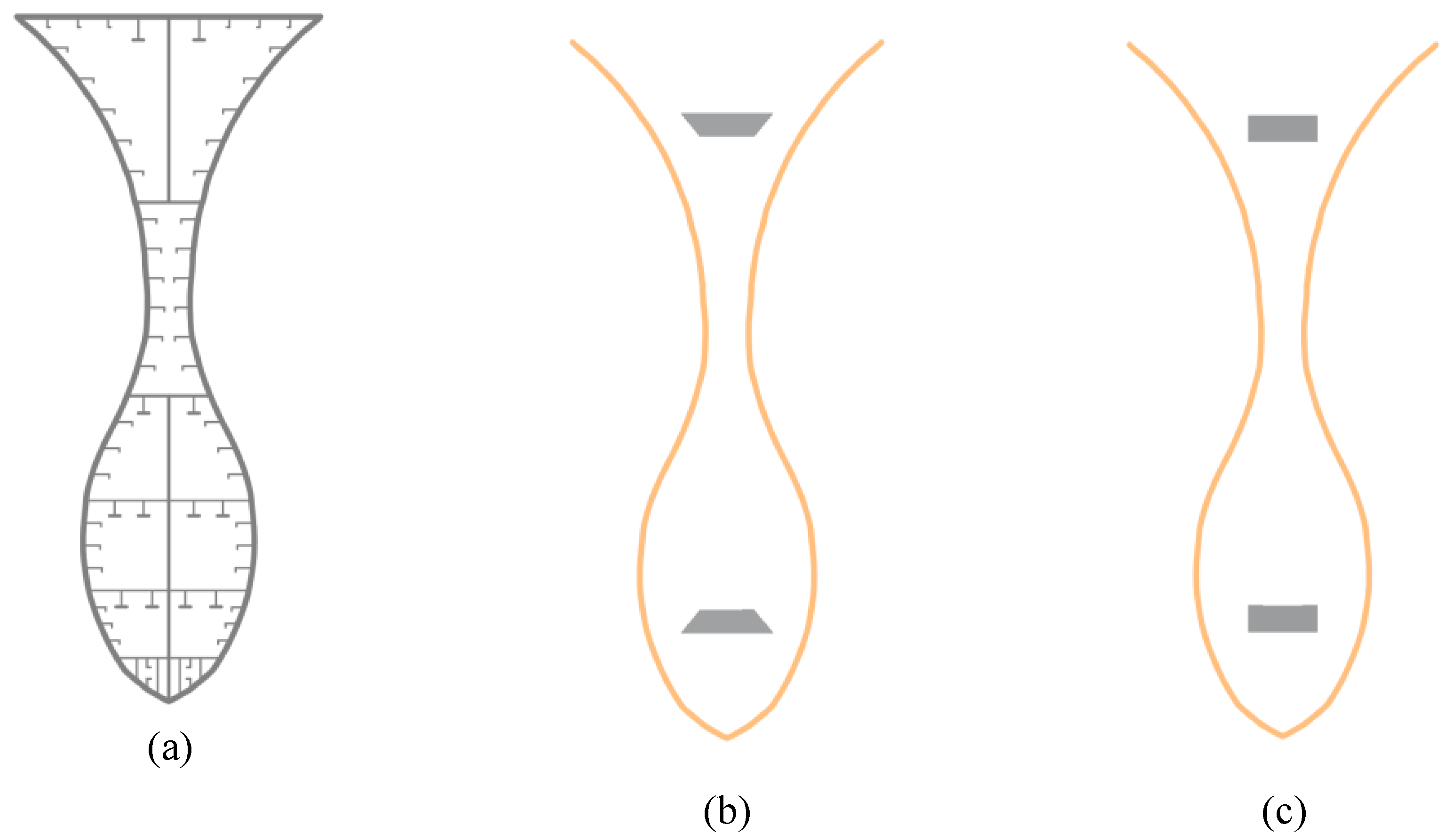
Figure 2.
Body plan of the targeted real ship.
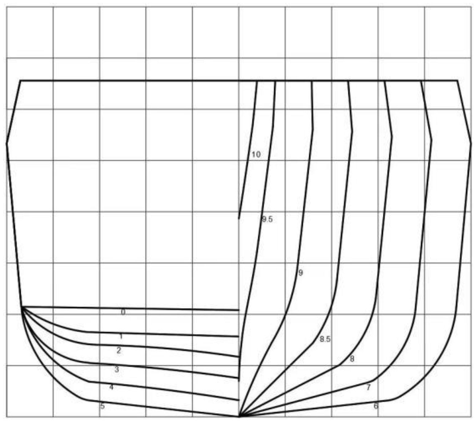
Figure 3.
Comparison of cross-sectional mass densities and second moments of area.
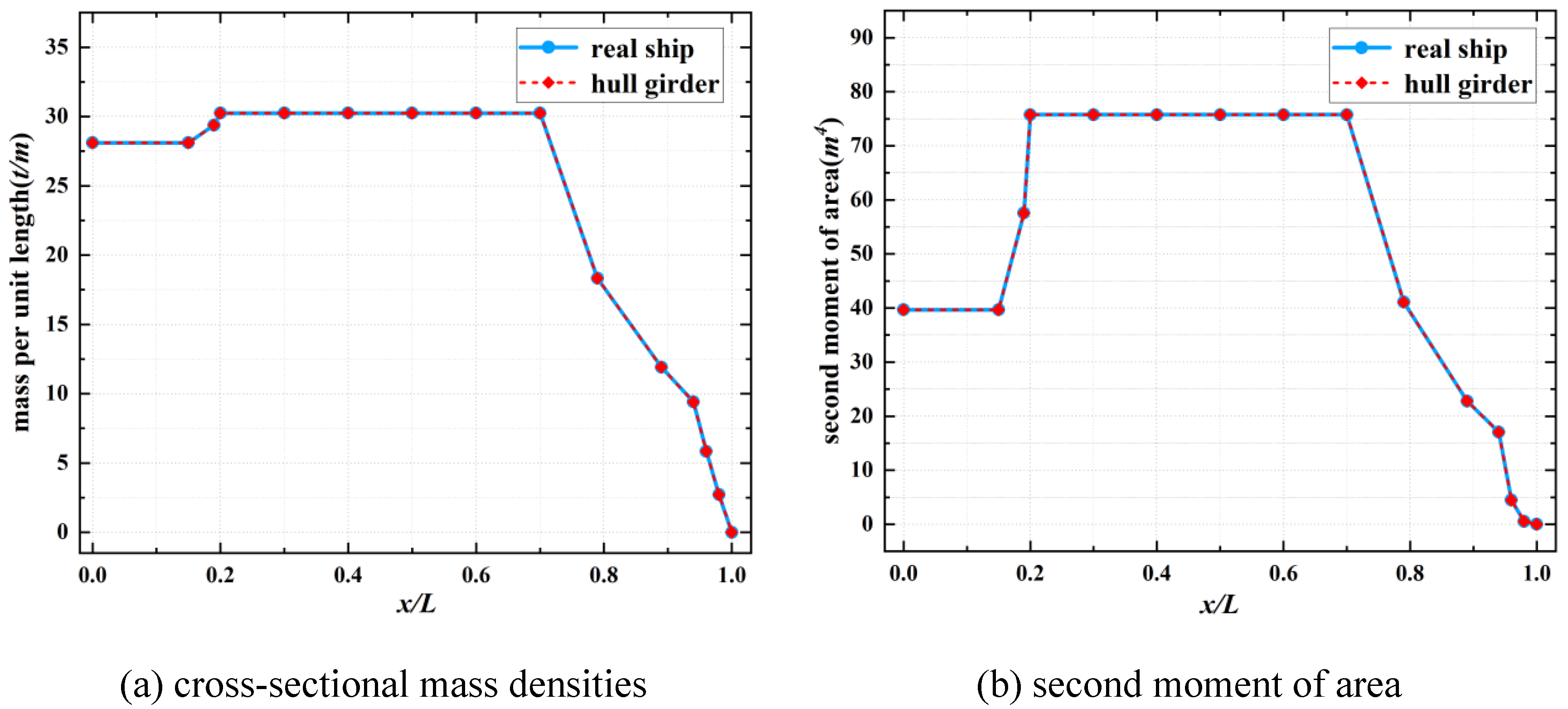
Figure 4.
FE modeling of the ship hull girder system.
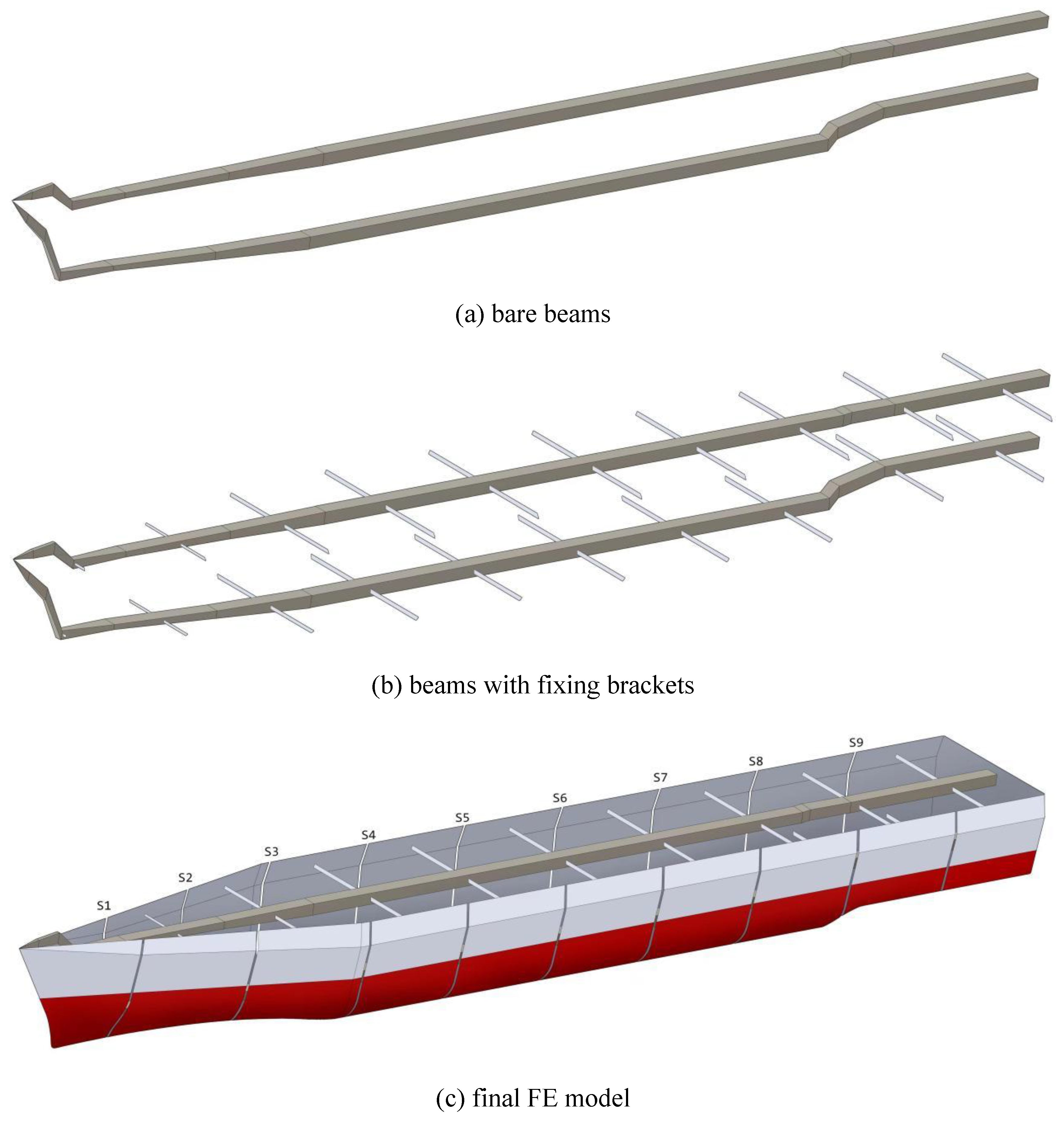
Figure 5.
Full-scale hull girder segment models.
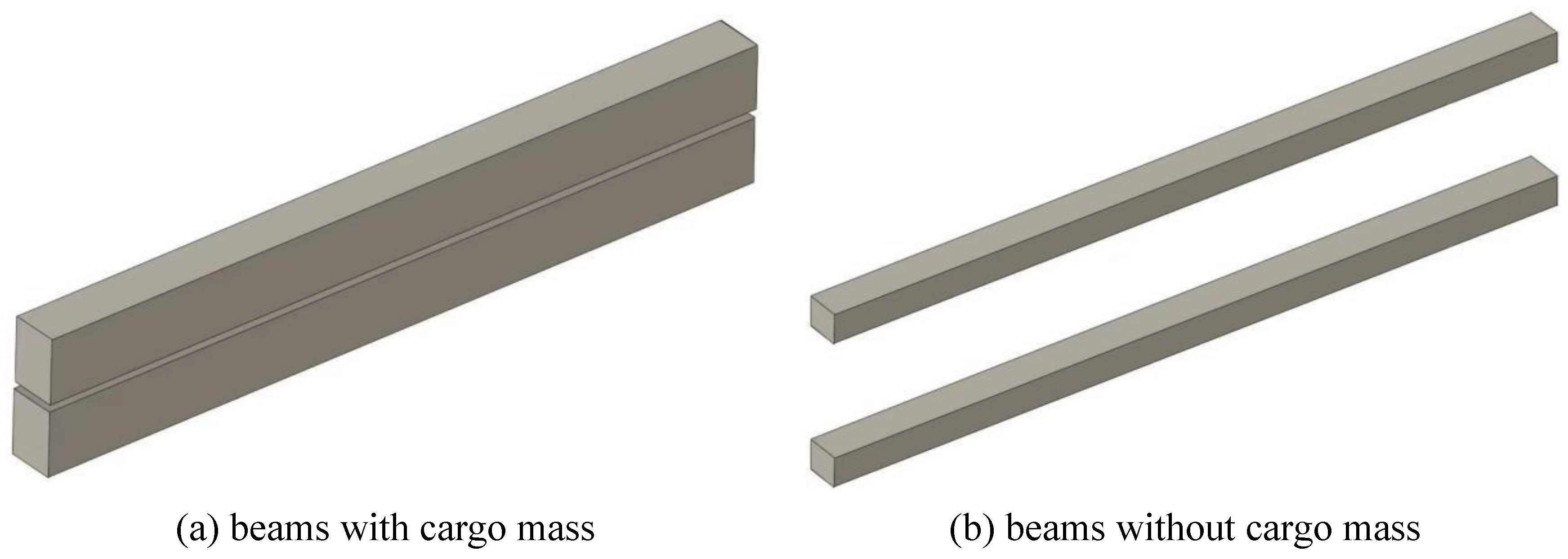
Figure 6.
Complete FE models for the chosen part of the parallel middle body.
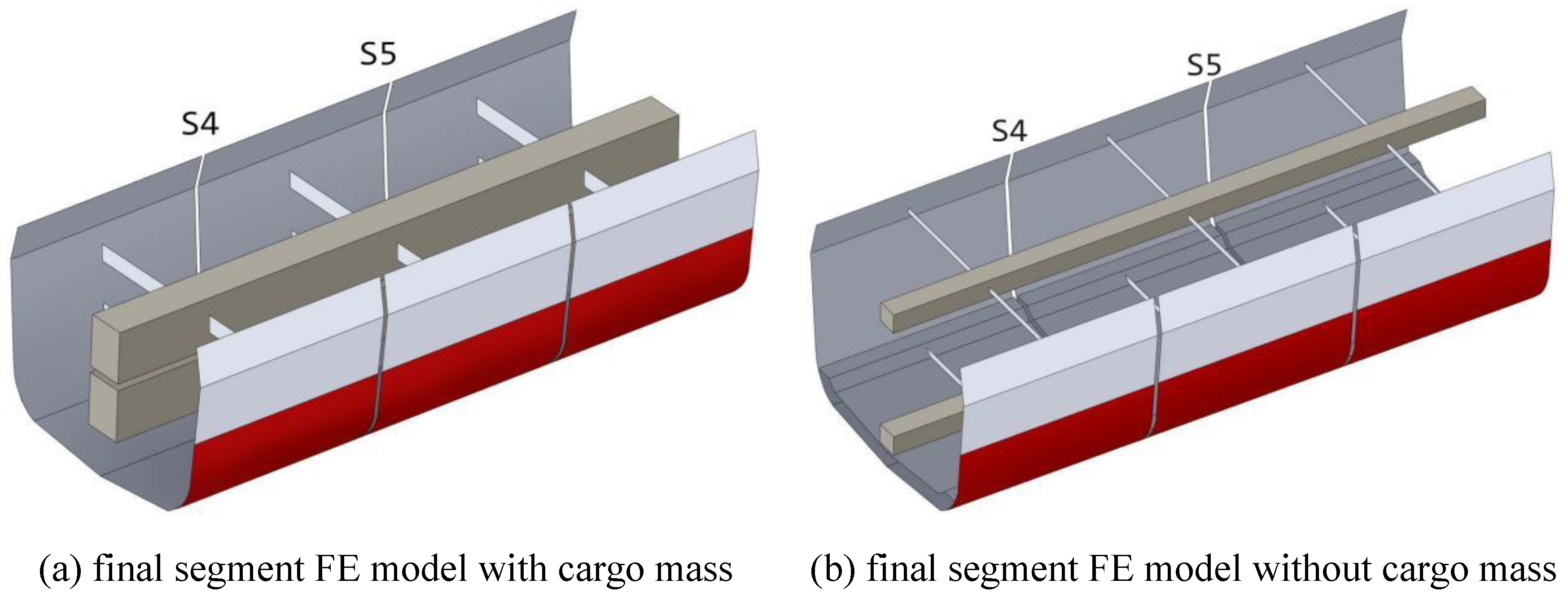
Figure 7.
FE model of the targeted real ship.
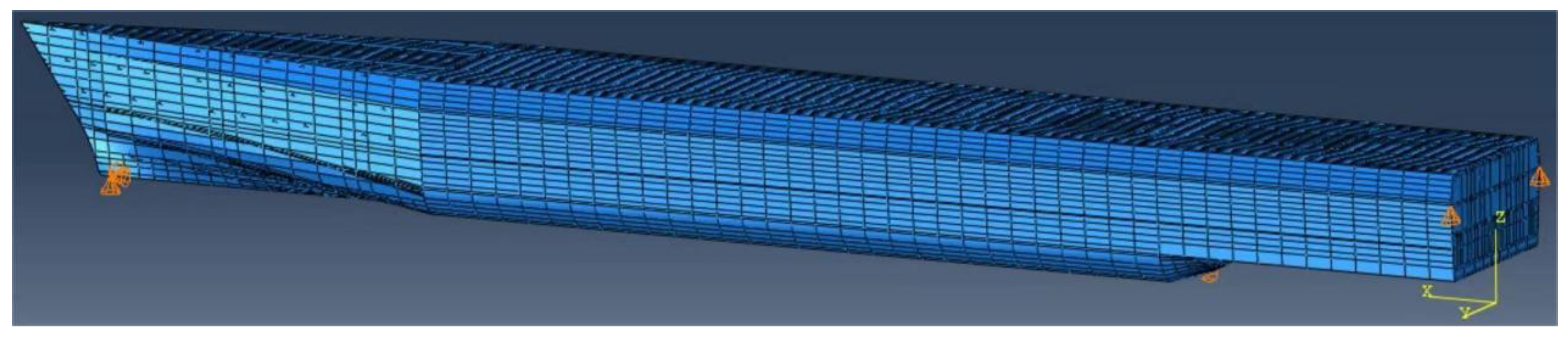
Figure 8.
Initial phase distribution in the dynamic wave pressures.
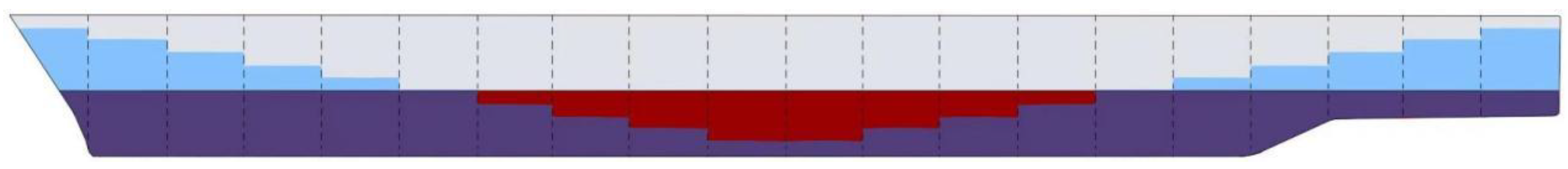
Figure 9.
Comparison of VBM between the hull girder and real ship FE models.
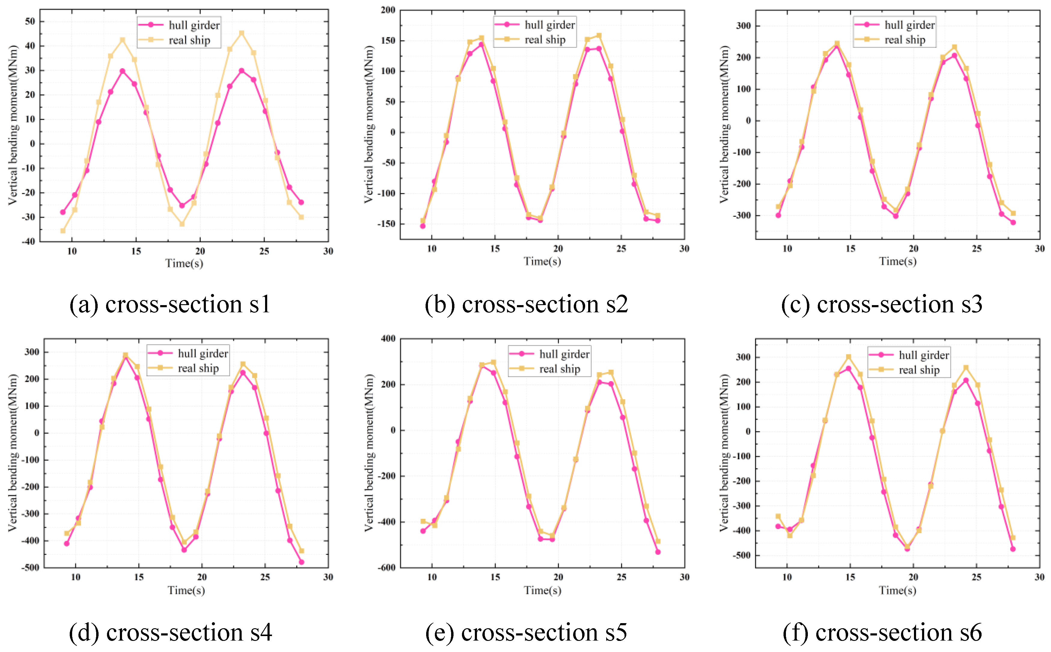
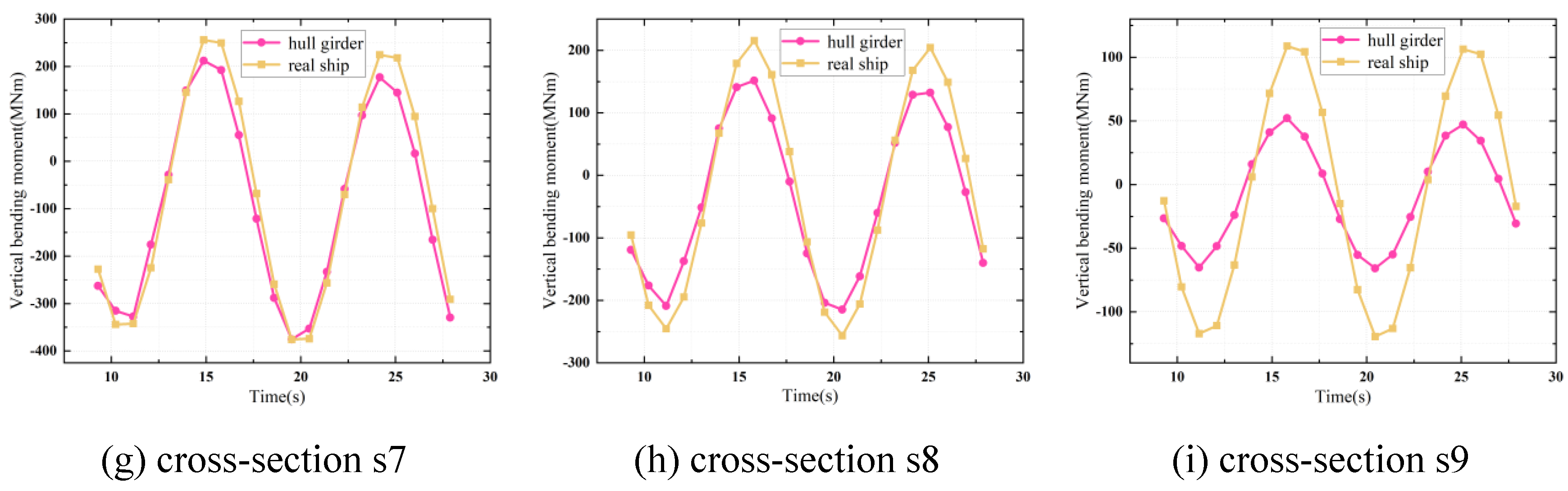
Figure 10.
Local real ship FE model corresponding to cross-section s5.
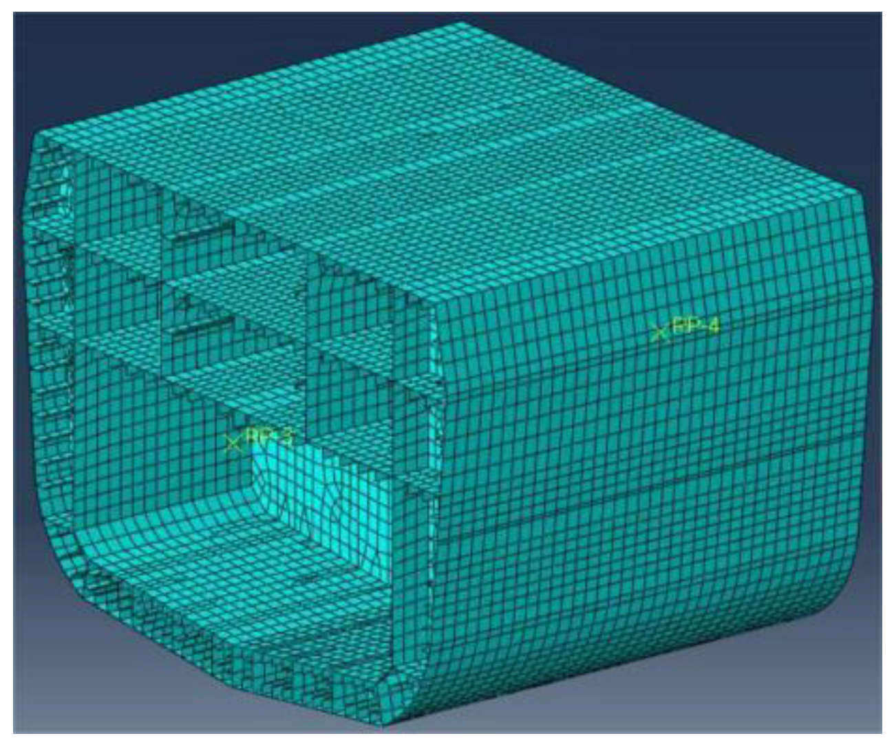
Figure 11.
Calculation locations for each cross-section.
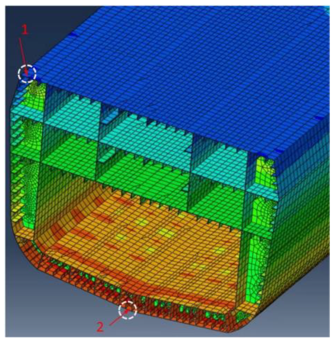
Figure 12.
Comparison of longitudinal bending stresses.
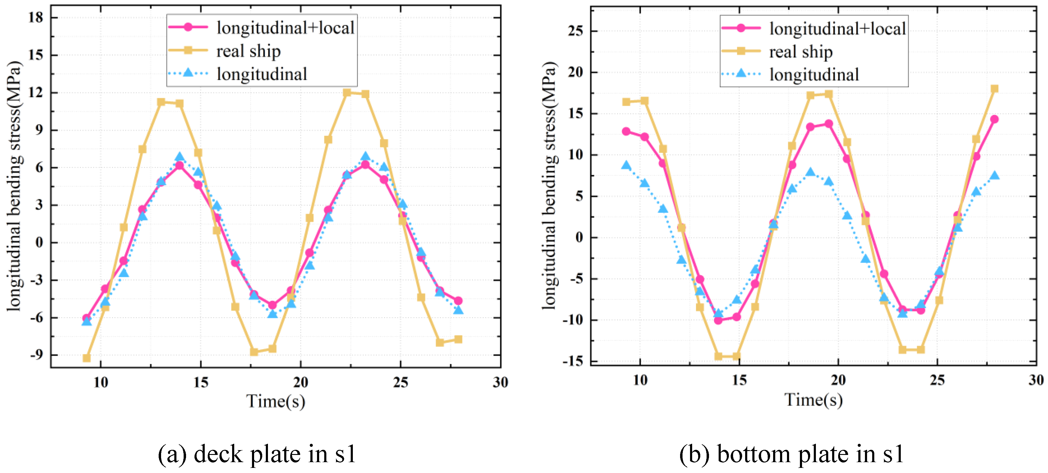
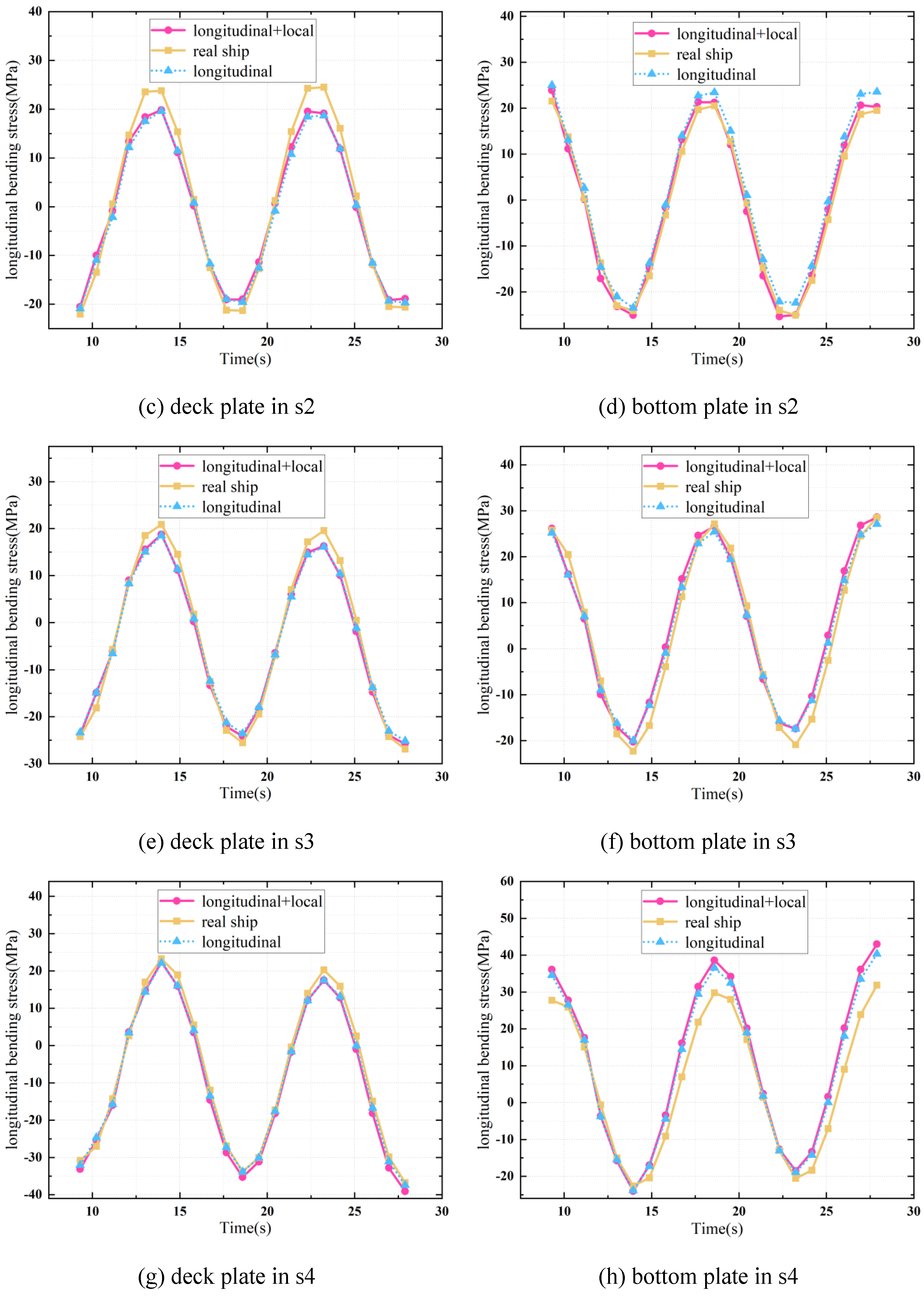
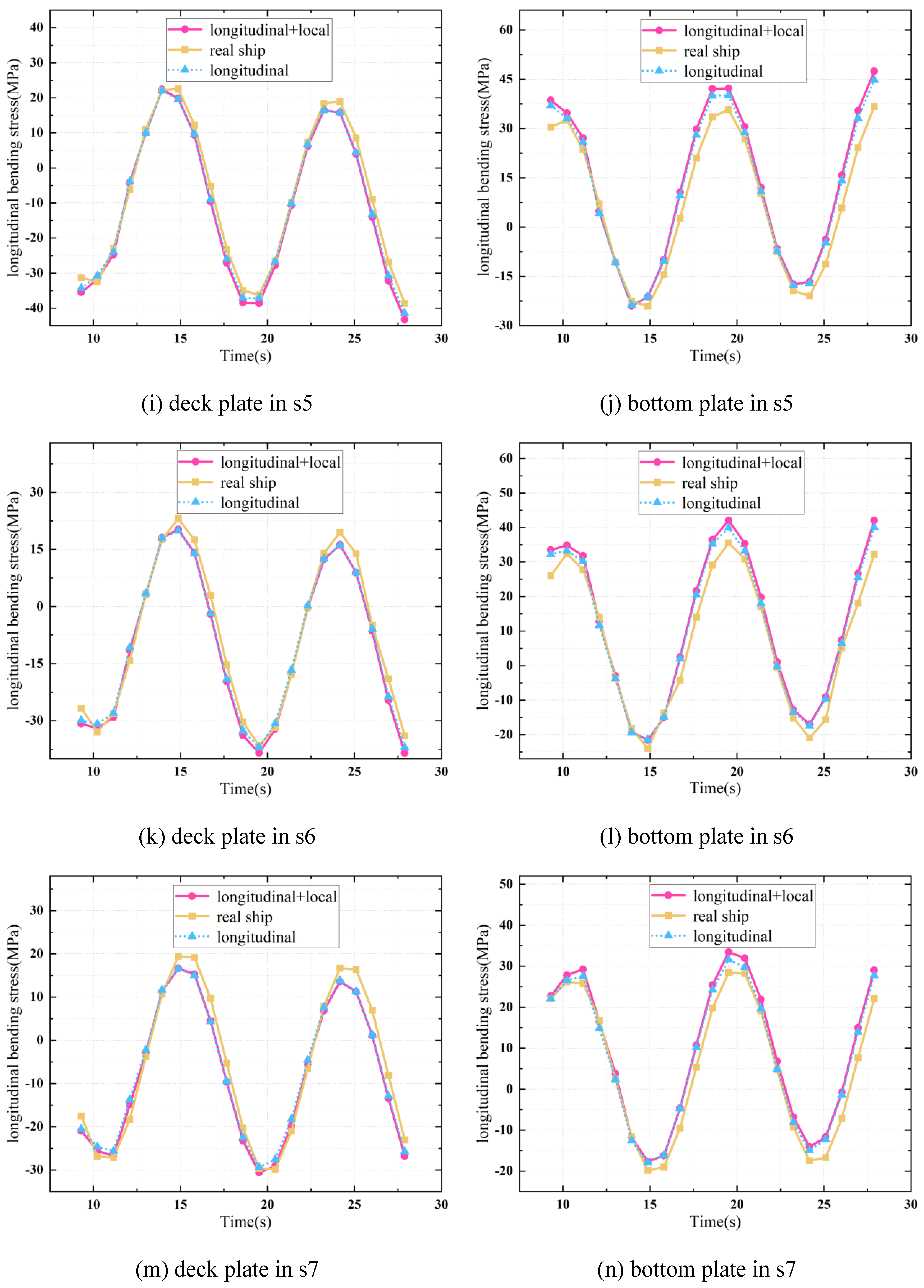
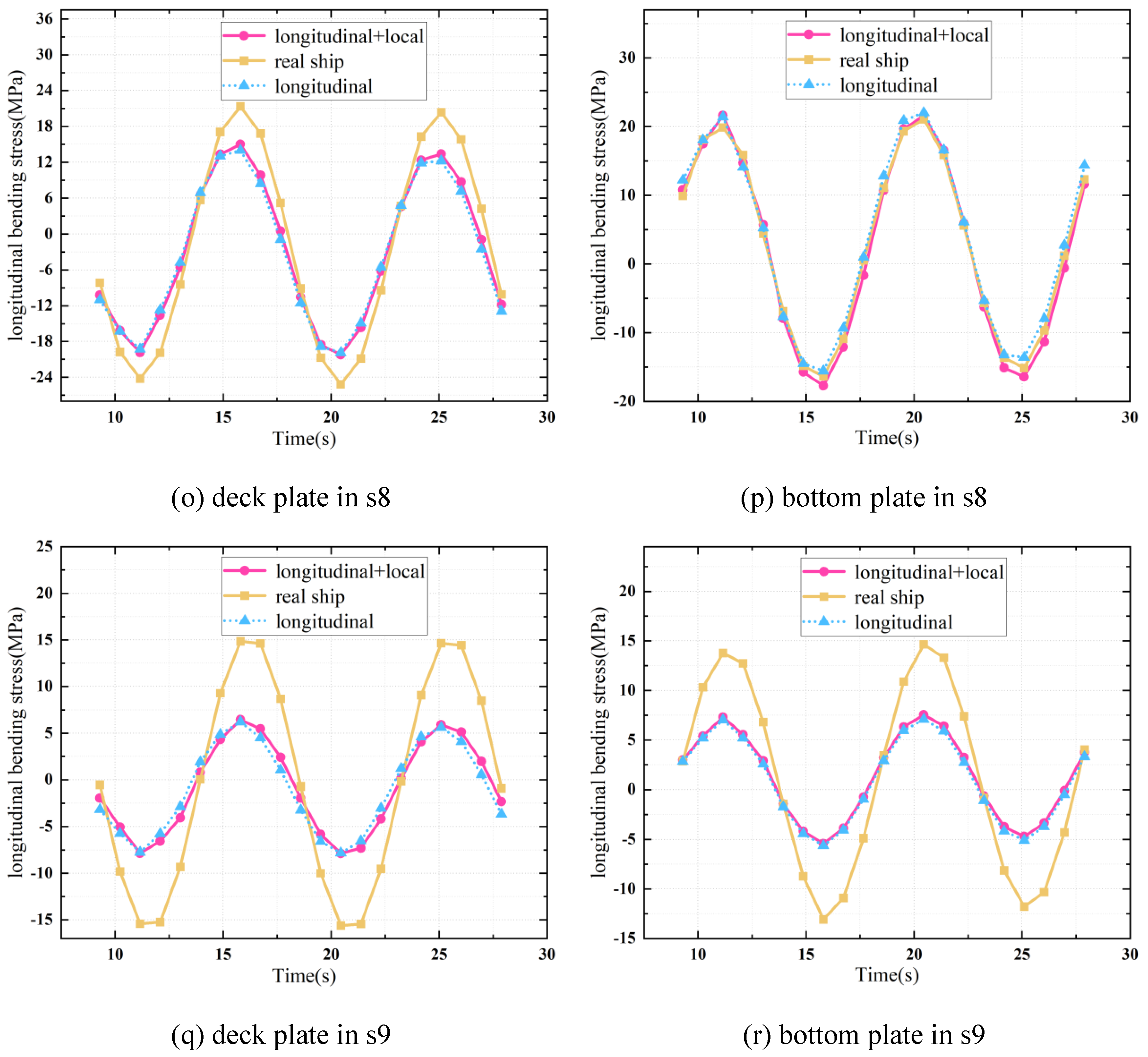
Figure 13.
Illustration of uniform and non-uniform backbone ship models.
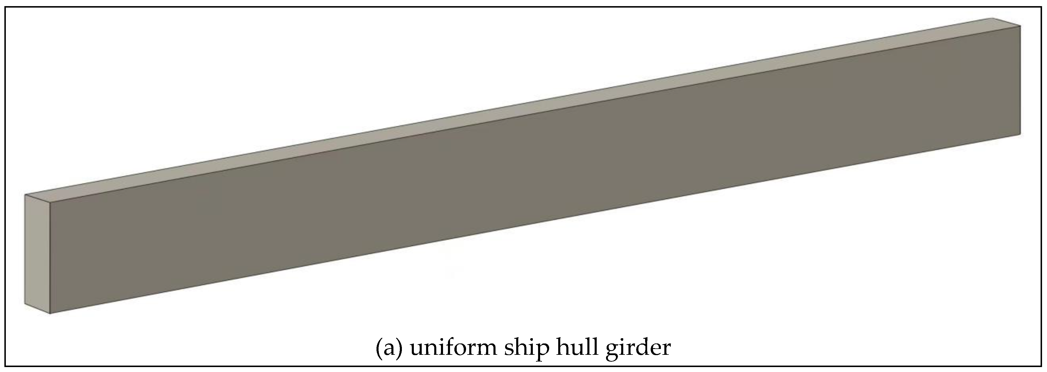
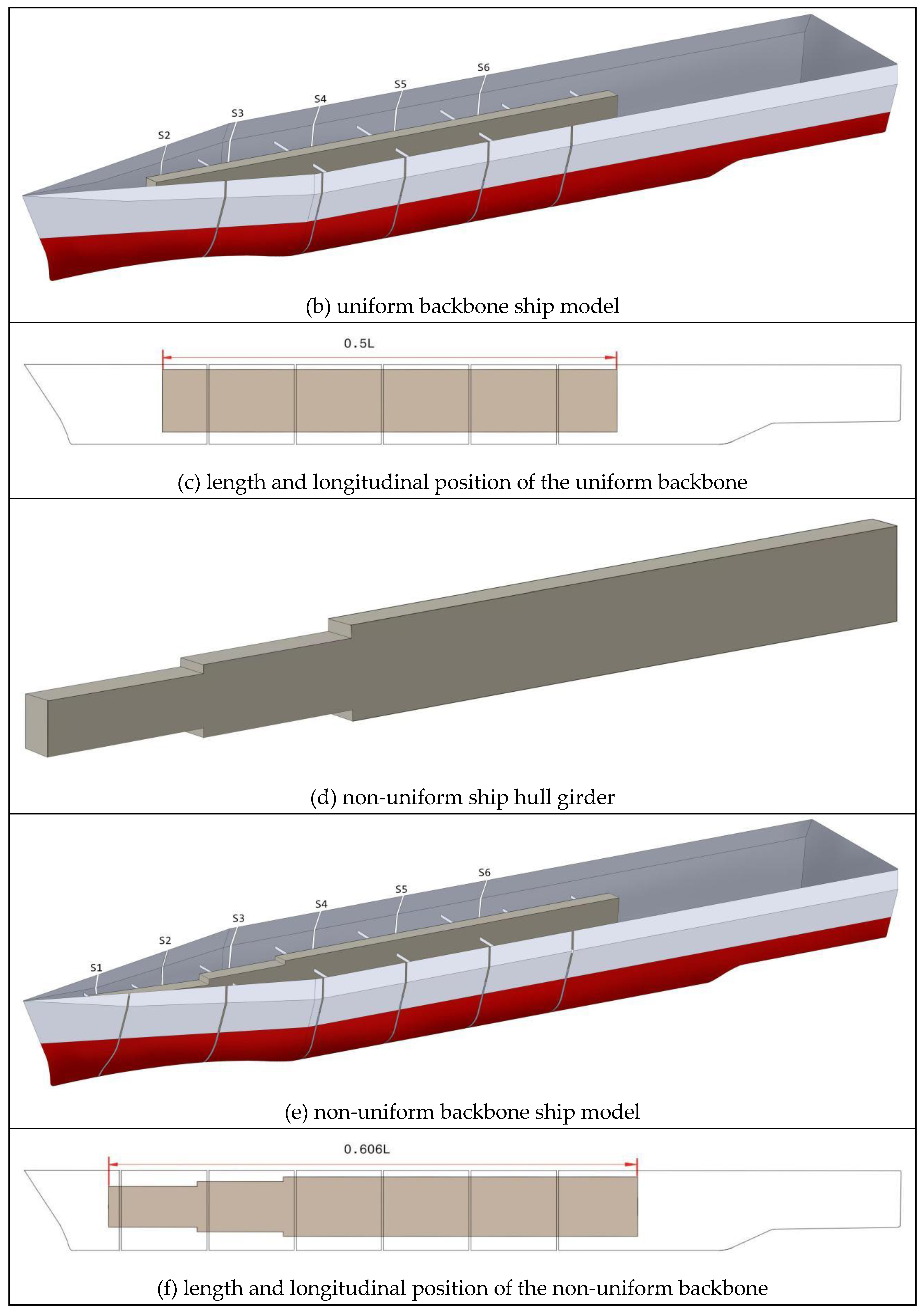
Figure 14.
Illustration of natural vibrational modes.
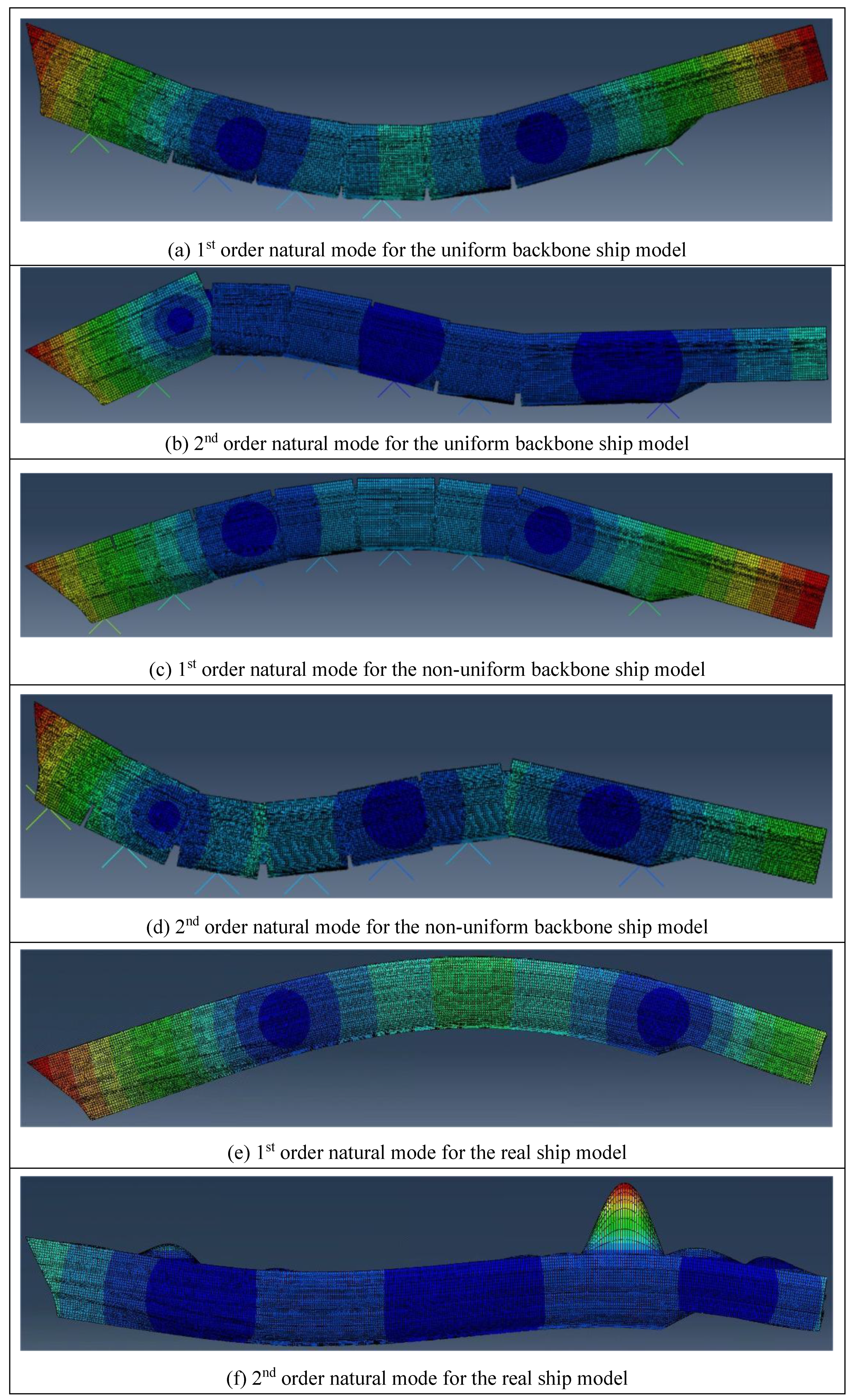
Figure 15.
Comparison of VBMs from different hull girder models.
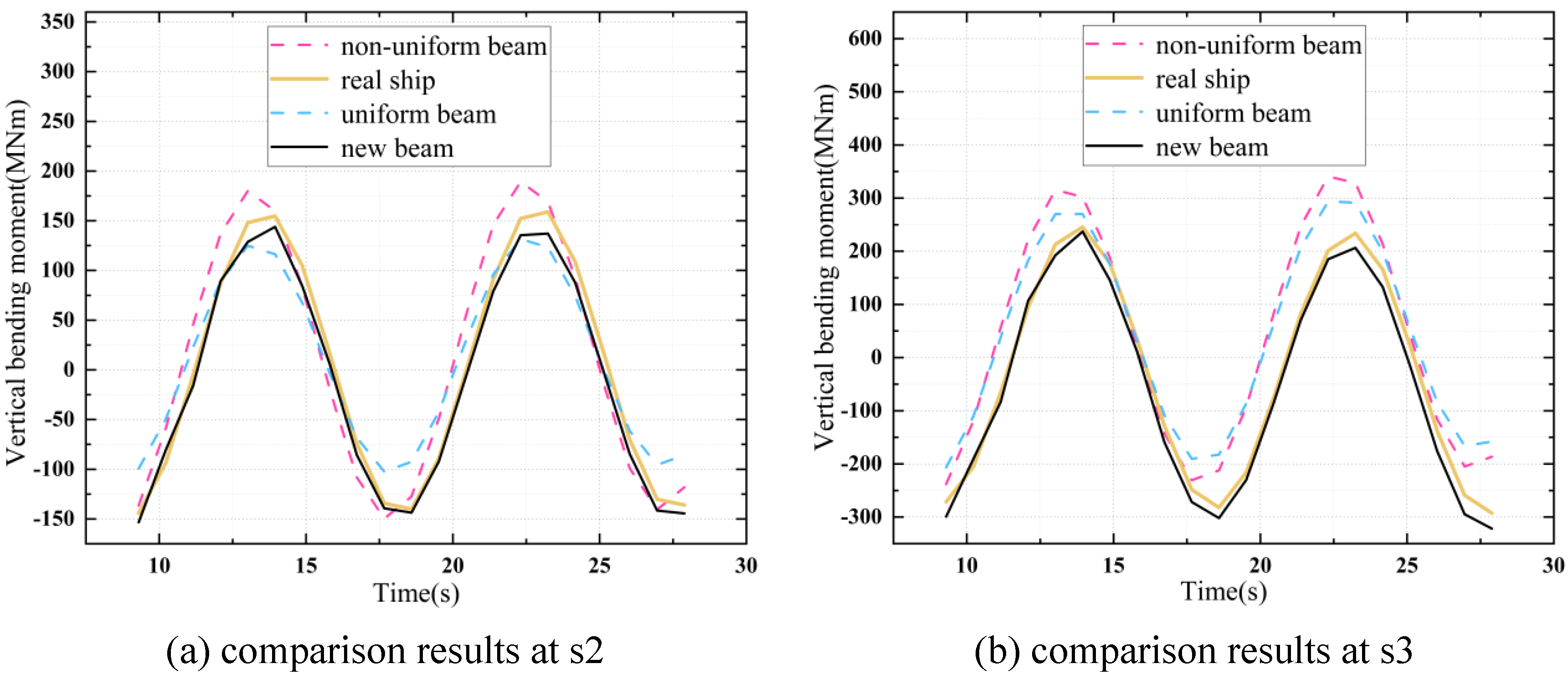
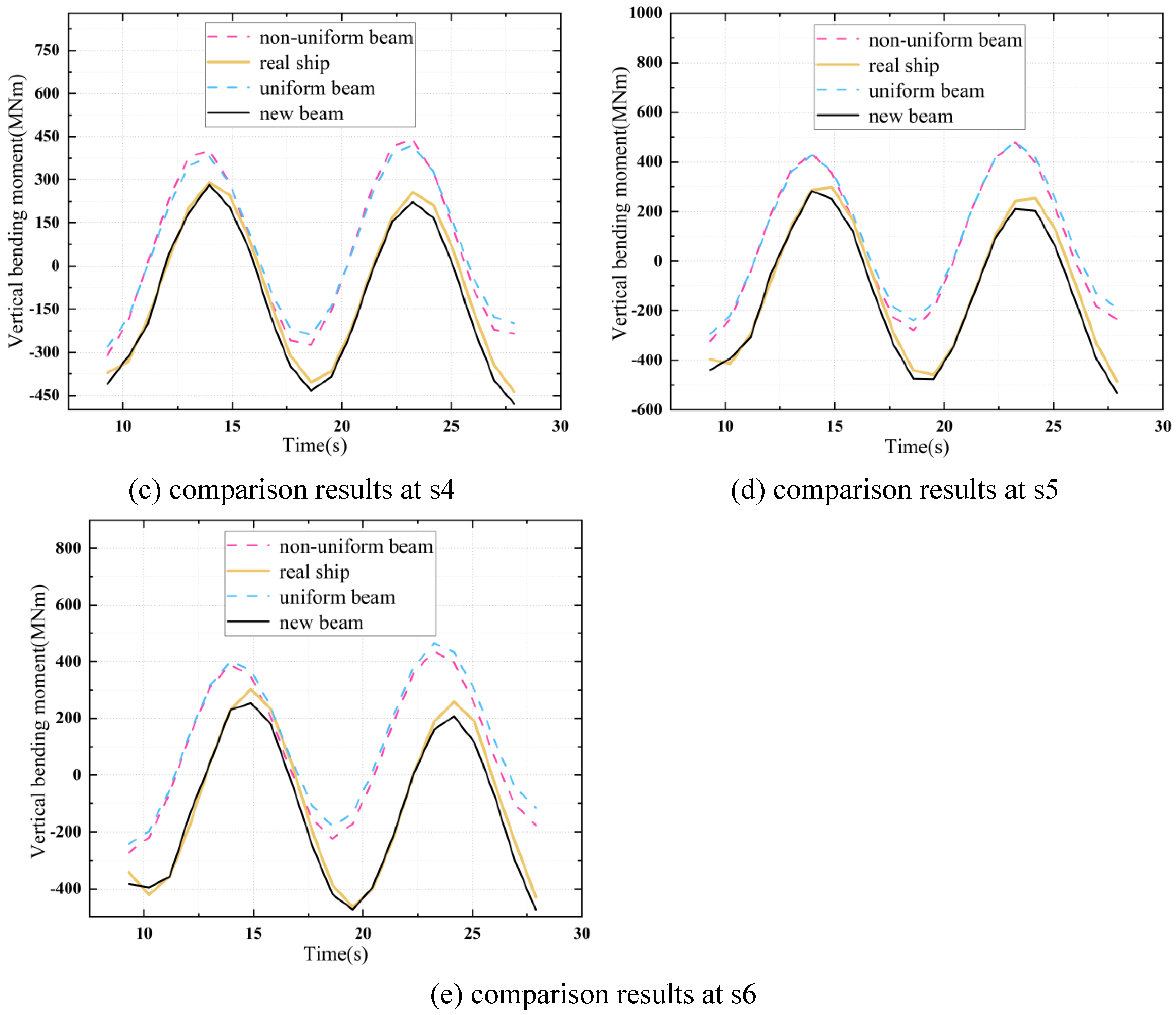

Table 1.
Main parameters of the overall cross-section.
| Item | Value |
|---|---|
| Density ρ(kg/m3) | 7800 |
| Area A(m2) | 2.304 |
| Height of COG ZG(m) | 9.016 |
| Second moment of area IZG(m4) | 85.461 |
Table 2.
Main parameters of the expected isosceles trapezoidal sub-cross-sections.
| Item | Value |
|---|---|
| Length of the upper parallel side WΩu(m) | 2.400 |
| Length of the lower parallel side WΩl(m) | 1.400 |
| Length of the upper parallel side WBu(m) | 1.400 |
| Length of the lower parallel side WBl(m) | 2.400 |
| Heights dΩl-dΩu, dBu-dBl(m) | 0.606 |
| Vertical distances TΩ, TB(m) | 6.088 |
Table 3.
Main parameters of the expected rectangular sub-cross-sections.
| Item | Value |
|---|---|
| Length wU(m) | 1.800 |
| Length hU(m) | 0.640 |
| Length wD(m) | 1.800 |
| Length hD(m) | 0.640 |
| Vertical distances dU, dD(m) | 6.023 |
Table 4.
Main particulars of the targeted real ship.
| Items | Value |
|---|---|
| Length overall Loa(m) Breadth B(m) Depth D(m) Design draft T(m) Displacement Δ(t) Block coefficient CB(m) |
135.00 17.00 12.30 6.00 8642.56 0.66 |
Table 5.
Main material properties of ship structures.
| Property | Value |
|---|---|
| Density ρ(kg/m3) | 7800 |
| Young’s modulus E(GPa) | 2.11 |
| Poisson’s ratio μ | 0.3 |
Table 6.
Basic parameters of the first hull girder segment.
| Item | Value |
|---|---|
| Length wU(m) | 2.500 |
| Length hU(m) | 3.377 |
| Length wD(m) | 2.500 |
| Length hD(m) | 3.377 |
| Vertical distances dU, dD(m) | 1.881 |
Table 7.
Comparison of peak values of VBM and VSF on s4 and s5.
| Cross-section ID | First model(peak values) | Second model(peak values) | Relative error | Relative error | ||
|---|---|---|---|---|---|---|
| VBM(MNm) | VSF(kN) | VBM(MNm) | VSF(kN) | VBM | VSF | |
| s4 | -182.7 | -1360.0 | -155.7 | -3000.0 | 17.3% | -54.7% |
| s5 | -200.0 | 698.0 | -172.9 | 1960.0 | 15.7% | -64.4% |
Table 8.
Main parameters for the targeted real ship and various ship models.
| item | real ship | uniform girder model | non-uniform girder model | |||
|---|---|---|---|---|---|---|
| value | relative error | value | relative error | |||
| natural frequency(Hz) | 1st | 0.74 | 0.71 | 4.1% | 0.72 | 2.7% |
| 2nd | 1.53 | 1.57 | 2.6% | 1.63 | 6.5% | |
| COG(m) | vertical | 6.68 | 6.56 | 1.8% | 6.40 | 4.2% |
| longitudinal | 60.76 | 60.76 | 0.0% | 60.76 | 0.0% | |
| moment of inertia(t×mm2;×1012) | 4.71 | 4.57 | 3.0% | 4.77 | 1.3% | |
Disclaimer/Publisher’s Note: The statements, opinions and data contained in all publications are solely those of the individual author(s) and contributor(s) and not of MDPI and/or the editor(s). MDPI and/or the editor(s) disclaim responsibility for any injury to people or property resulting from any ideas, methods, instructions or products referred to in the content. |
© 2024 by the authors. Licensee MDPI, Basel, Switzerland. This article is an open access article distributed under the terms and conditions of the Creative Commons Attribution (CC BY) license (http://creativecommons.org/licenses/by/4.0/).
Copyright: This open access article is published under a Creative Commons CC BY 4.0 license, which permit the free download, distribution, and reuse, provided that the author and preprint are cited in any reuse.


