
Submitted:
24 November 2024
Posted:
25 November 2024
You are already at the latest version
Abstract
This paper present analysis of electric field distribution on windings of primary side of high frequency, and voltage transformers with variables characteristics. To study the effect of high transformer voltage, induce and high frequency for finding suitable dimension. The objective is analysis of electricity field distribution at the low voltage at the angle 0, 30, 45, 60, and 90 degrees, Comparing voltage flow out of the putting primary coil. Comparing external frequency of primary coil putting. Comparing result of distribution electricity field model between primary coil (Lp) and secondary coil. By consideration from induce that proper for Tesla transformer reproduce by using FEMLAB program. Comparing the Tesla transformer reproduce which is created the frequency 120 kHz and voltage at 120 kV. Analysis use FEMLAB program. The result isn’t flash over between the low and high voltage winding.
Keywords:
tesla transformer
; primary winding
; secondary winding
; FEMLAB program
1. Introduction
At the present electric distribution system in bus far from ele. In the manufacture to produce Porcelain Insulator, it would use high voltage transformer to distribute the voltage for testing every insulator that produce from the manufacturer to check the primary quality that the insulators are not imperfect in the Porcelain insulator. By using flash over the surface of insulators which is follow the standard ANSI C.29.1976 that using the high frequency in testing the defect inside. It would be effect to the high electricity field stress that occur between secondary, and primary coil because this type of transformer is the air axis transformer. It would be a problem in the insulator coil that has the electric air by creating the flash over on the 2 sets of coils. The suitable distance of coil would be reducing that problem. To reduce the problem, it should not make the voltage out of high frequency, and voltage transformers which has set a determine amount. So that, this research would be study the effect of high frequency, and voltage transformers induce (Transformer of Tesla). To find suitable dimension by analyst the result that occurs in this research. It would use the model circuit of tesla transformer by using FEMLAB program. Compare with the testing results that receive from buildup transformer of Tesla [1].
Coil of Tesla was invented by Tesla. The resonance between side of secondary coils on the transformer is the operating principle of the Tesla coil [2]-[3]. Transformer of Tesla is device that provide electrical high potential.
Voltage is generated from damped oscillations at a frequency of 50 to 400 kilohertz. The Tesla transformer was created to effectively test the electrical conditions of suspensions and post-type insulators [4]-[5]. The high-voltage pulses generated will have an amplitude of several megavolts and can discharge electricity over several meters [6]-[7].
In 2008, the electric field and components were optimally designed using the FEMLAB software. The IEC standard was used to determine the PD value in the design of the cable terminator and to design the cable connector with SF6 insulation. The electrical stress was analysed [8]. In 2010, a cost-effective high-performance transformer of Tesla was constructed, and designed for test a insulator. The transformer output was designed at 500 kV. This article presents results of experimental and simulation from transformer of Tesla to suit main design parameters [9].
Therefore, this paper analysed of electric field distribution on primary windings of high voltage high frequency transformers with variables characteristics.
The objective of this paper as follow:
- The analysis of electricity field distribution at the low voltage at the angle 0, 30, 45, 60, and 90 degree.
- Comparing voltage flow out of the putting primary coil.
- Comparing external frequency of primary coil putting.
- Comparing result of distribution electricity field model between primary coil (Lp) and secondary coil.

Table 1.
The tube size and the high that suitable for binding high voltage coil.
| L1 | Primary | Secondary | ||
| L1 (μH) |
C1 (μF) |
L2 (mH) |
C2 (PF) |
|
| 90o | 28.45 | |||
| 60o | ||||
| 450 | 72.09 | 6.366 | 43.97 | 40 |
| 30o | ||||
| 0o | 64.70 | |||
2. Equipment and Research Model
Equipment that using in the research as follow:
1. MATLAB Program–using the tesla transformer model to be a design before building up the real one.
2. FEMLAB Program using to be a model of distribution the electricity field in tesla transformer.
3. PVC tube that has diameter 4 inch – using to be axis for Ls secondary coil binding.
4. Enamel Copper Coil size 31 SWG – using to be a LS secondary coil binding.
5. Copper tube 0.03 inch that diameter 0.25 inch and 0.5 inch. – using to be a Lp primary coil and Transformer Protection Ring.
6. Motor 1 phase – speed at 1450 round per second using for drive the Rotary Spark cap.
7. Low Voltage Capacitor polypropylene size 15 nF 1,600 V
8. Neon Sign Transformer 230 V/15,000V using for transformer power distributor of low voltage tesla transformer.
3. Method
1. High voltage circuit model, high frequency voltage at 120 kV, high voltage at 120 kHz by using MATLAB and FEMLAB Program.
2. Create the model of components and several structure of high voltage high frequency.
3. Build up the components and several structure of high voltage high frequency.
4. Testing to find the best feature in working of high voltage high frequency and correct the defect part.
5. Collect the result from the calculation and the result from the model that using FEMLAB Program and the result of high voltage high frequency that built up to compare.
6. Conclusion of research and testing Tesla transformer circuits.
Transformer of Tesla circuit is shown in Figure 1.
From Figure 1.
- C1
- is main capacitor.
- L1
- is main inductor.
- C2
- is secondary capacitor.
- L2
- is secondary inductor.
- Q
- is spark gap.
High voltage is 120 kVrms. Frequency is 120 kHz. Voltage impulse is 0–15 kVrms. Capacity C2 value around 40 pF. Equation that uses for calculating parameter [10]-[12].
- In case that oscillation has occur between L1 and C1 the frequency that would occur can calculate in equation 1.
- Condition that occur from oscillation low voltage induce and high voltage tune [13] can calculate in equation 2.
| Where | f1 | is primary resonant frequency (Hz). |
| L1 | is primary inductance (H). | |
| C1 | is primary capacitance (F). |
Table 2.
The tube dimeter and coil binding.
| Diameter (inch) | High/diameter | Length of coil binding (inch) |
|---|---|---|
| 3 | 6.0:1 | 18.0 |
| 4 | 5.0:1 | 20.0 |
| 5 | 4.5:1 | 22.5 |
| 6 | 4.0:1 | 24.0 |
| 7 | 3.5:1 | 24.5 |
| 8 | 3.0:1 | 24.0 |
| More 8 | 3.0:1 | 24.0 |
Figure 2.
The dimension in binding high voltage coil [14].
Figure 2.
The dimension in binding high voltage coil [14].
| Where | L | is induce (mH). |
| R | is diameter radius to the center of coil (Inch). | |
| N | is binding amount. | |
| H | is high of binding (Inch). |
Low voltage coil model
1. Angle with the floor at 30o, 45o, 60o, using copper tube size 5/16 inch, thick 0.03 inch for low voltage coil.
Figure 3.
The primary coil at the angle 30o, 45o, 60o [15].
Figure 3.
The primary coil at the angle 30o, 45o, 60o [15].

From Fig. 3.
| Where | W | is diameter of copper tube = 5/16 inch. |
| S | is binding distance = 1/2 inch. | |
| DI | is inside diameter of Lp = 14 inch. | |
| DO | is outside diameter of Lp = 34 inch. | |
| N | is Lp binding = 10 round. |
Angle to the floor at 0o using copper tube size 5/16 inch, thick 0.03 in to be low voltage [16].
Figure 4.
The primary coil at the angle 0o.

4. Results
The model of electricity field distribution of high voltage high frequency transformer that follow to finite element process by using FEMLAB program. It is determined that voltage in the low coil should have electricity voltage at 15 kV. The high voltage coil has permittivity tube of PVC size 3.5, and 120 kV of voltage [14]-[15].
The comparison of electricity field model, and angle of low voltage five degrees viz ninety, sixty, forty-five, thirty, and zero degrees. The result of model of electricity field distribution at the low voltage are shown in Figure 5–10.
Figure 5 shows the amount of electricity field maximum equal to 20.99 kV/cm (1st dimension).
Figure 6 shows the amount of electricity field maximum equal to 15.20 kV/cm (2nd dimension).
Figure 7 shows the amount of electricity field maximum equal to 13.95 kV/cm (3rd dimension).
Figure 8 shows the amount of electricity field maximum equal to 14.91 kV/cm (4th dimension).
Figure 9 shows amount field of electricity maximum equal to 14.99 kV/cm (5th dimension).
The testing result which have put the Lp coil at the angle 90, 60, 45, 30, 0 degree. Oscillation that retains it should be calculated in each type The tesla transformer testing result which have put the Lp coil at the angle 90, 60, 45, 30, 0 degree. Oscillation that retains it should be calculated in each type.
Figure 11.
Testing in putting Lp coil at the angle 90 degree and Wave that could calculate of Lp at the angle 90 degree.
Figure 11.
Testing in putting Lp coil at the angle 90 degree and Wave that could calculate of Lp at the angle 90 degree.
Figure 12.
Testing in putting Lp coil at the angle 60 degree and Wave that could calculate of Lp at the angle 60 degree.
Figure 12.
Testing in putting Lp coil at the angle 60 degree and Wave that could calculate of Lp at the angle 60 degree.
Figure 13.
Testing in putting Lp coil at the angle 45 degree and Wave that could calculate of Lp at the angle 45 degree.
Figure 13.
Testing in putting Lp coil at the angle 45 degree and Wave that could calculate of Lp at the angle 45 degree.
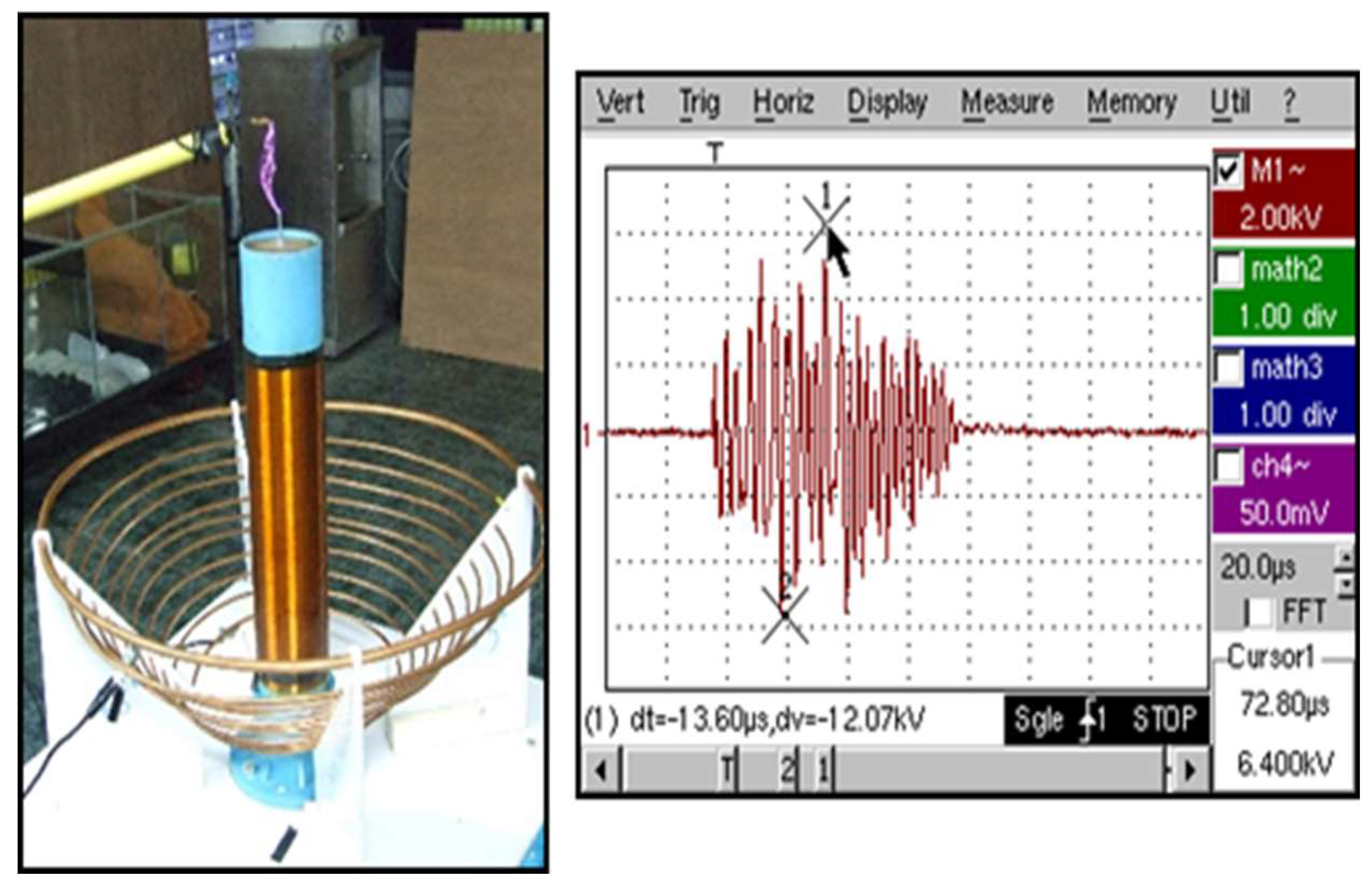
Figure 14.
Testing in putting Lp coil at the angle 30 degree and Wave that could calculate of Lp at the angle 30 degree.
Figure 14.
Testing in putting Lp coil at the angle 30 degree and Wave that could calculate of Lp at the angle 30 degree.
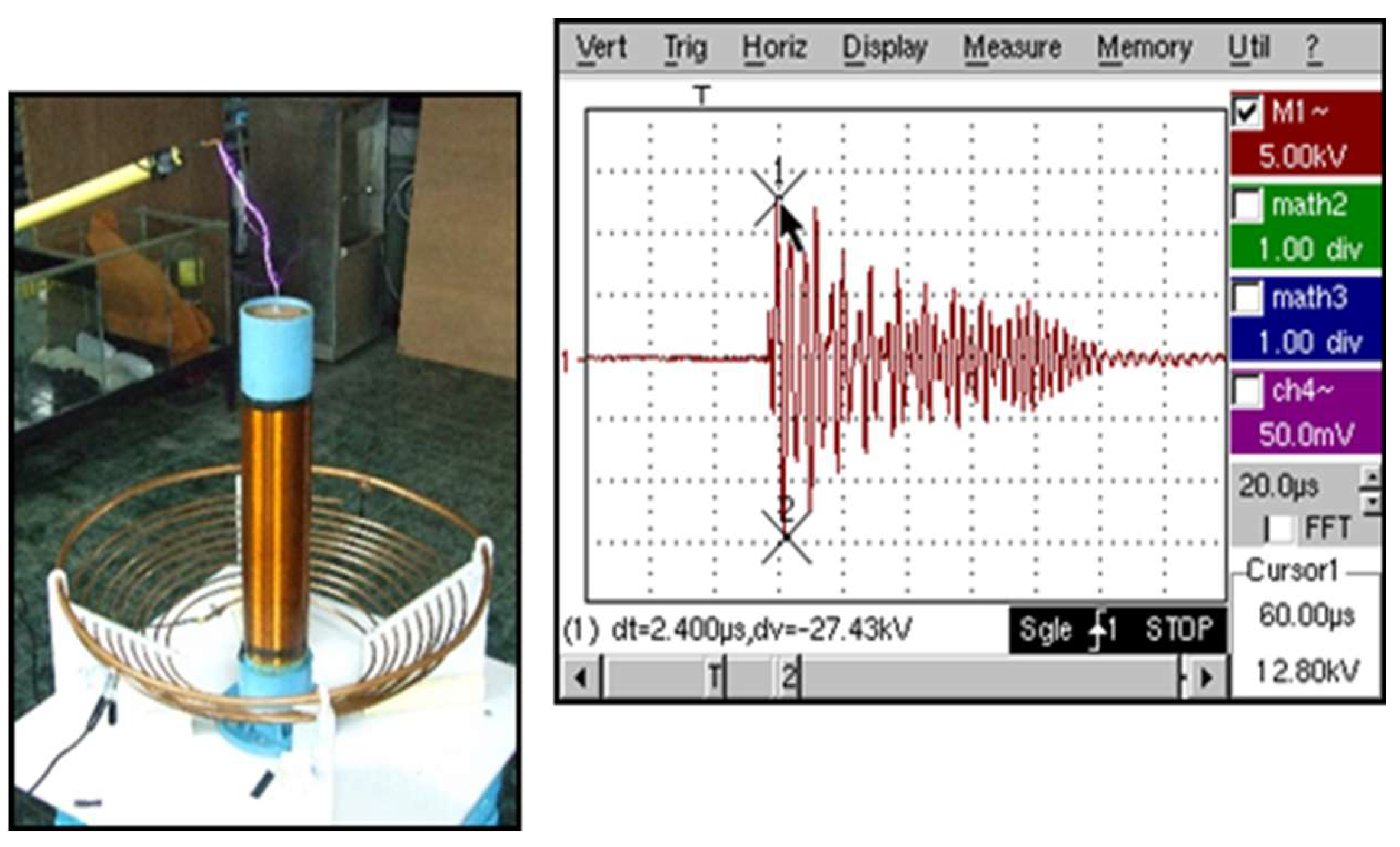
Figure 15.
Testing in putting Lp coil at the angle 0 degree and Wave that could calculate of Lp at the angle 0 degree.
Figure 15.
Testing in putting Lp coil at the angle 0 degree and Wave that could calculate of Lp at the angle 0 degree.
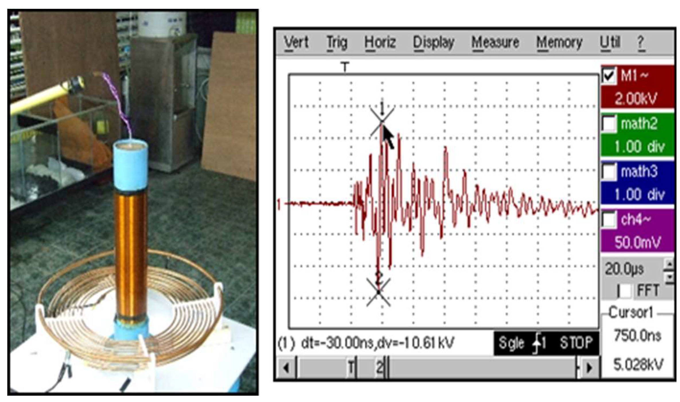
Table 3.
The results of voltage flow out of the putting primary coil at the adjust position from the round 8 in each type.
Table 3.
The results of voltage flow out of the putting primary coil at the adjust position from the round 8 in each type.
| Primary Coil Position (Lp) | External Voltage (kV) | |||
|---|---|---|---|---|
| 1 th Without Toroid |
2nd Without Toroid |
3rd With Toroid |
Remarks | |
| 0o | 106.1 | 96 | 102.4 | |
| 30o | 274.3 | 139.9 | 105.1 | |
| 45o | 120.7 | 131.7 | 102.4 | |
| 60o | 104.2 | 129.8 | 157.7 | |
| 90o | 107.9 | 129.8 | 212.6 | 1st and 3rd Breakdown |
Comparing of voltage flow out of putting primary coil is shown in Figure 16.
Table 4.
The results of external frenquency of primary coil putting at the adjust position at 8 round binding in each type.
Table 4.
The results of external frenquency of primary coil putting at the adjust position at 8 round binding in each type.
| Primary Coil Position (Lp) | External Frequency (kHz) | ||
|---|---|---|---|
| 1 th Without Toroid |
2nd Without Toroid |
3rd With Toroid |
|
| 0o | 102 | 128 | 125 |
| 30o | 108 | 122 | 120 |
| 45o | 110 | 138 | 130 |
| 60o | 135 | 127 | 120 |
| 90o | 125 | 145 | 135 |
Figure 17.
Comparing of external frequency of primary putting.
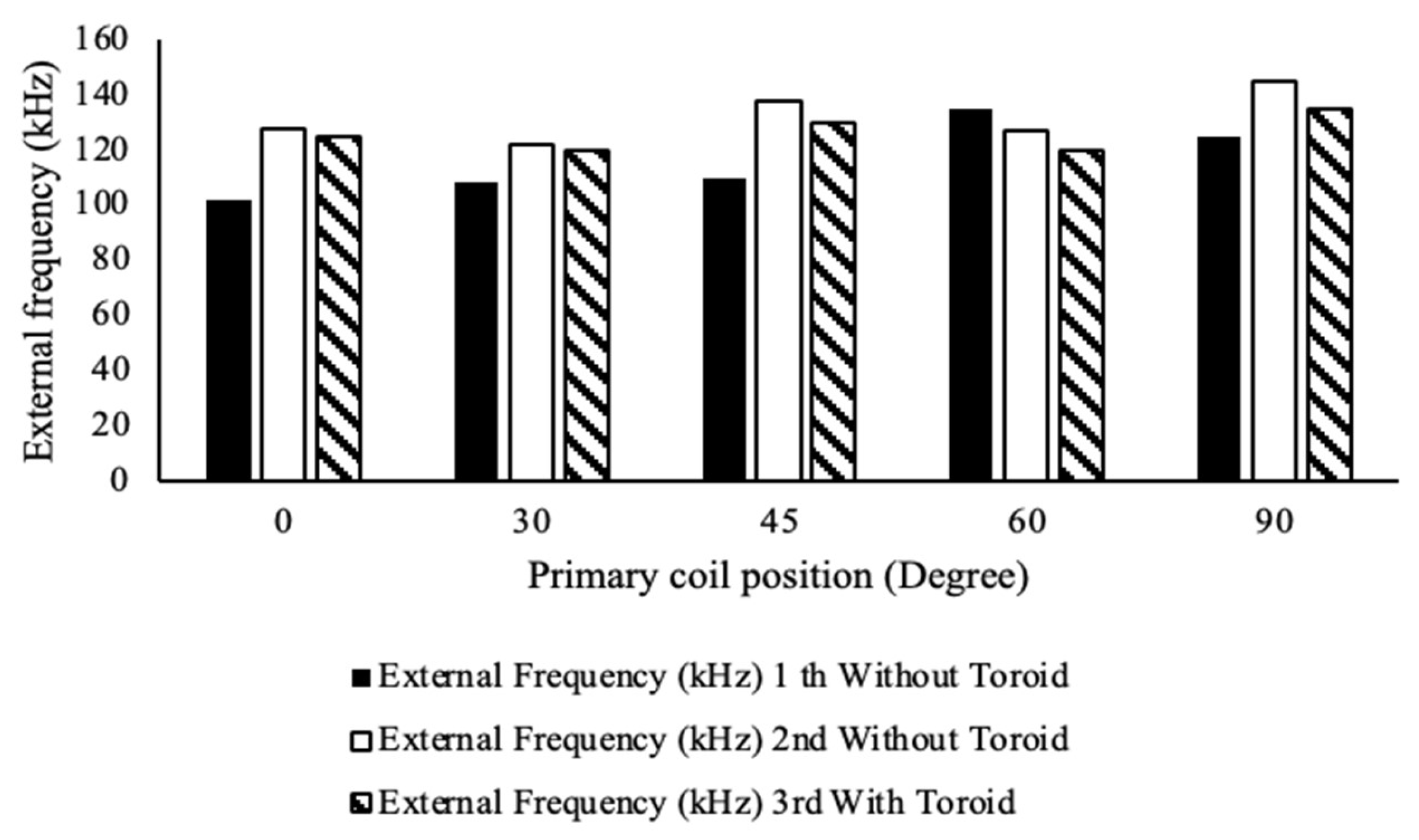
Table 5.
The results of distribution electricity field model between primary and secondary coil in several angle by using FEMLAB and calculation.
Table 5.
The results of distribution electricity field model between primary and secondary coil in several angle by using FEMLAB and calculation.
| Primary Coil Position (Lp) | Maximum of Electricity Field (kV/cm) | |
|---|---|---|
| Model Testing by using FEMLAB Program | Calculating Result by using the formula | |
| 0o | 14.99 | 12.48 |
| 30o | 14.91 | 13.16 |
| 45o | 13.95 | 14.00 |
| 60o | 15.20 | 15.15 |
| 90o | 18.23 | 17.32 |
Figure 18.
Comparing of distribution electricity field model between primary coil (Lp) and secondary coil.
Figure 18.
Comparing of distribution electricity field model between primary coil (Lp) and secondary coil.
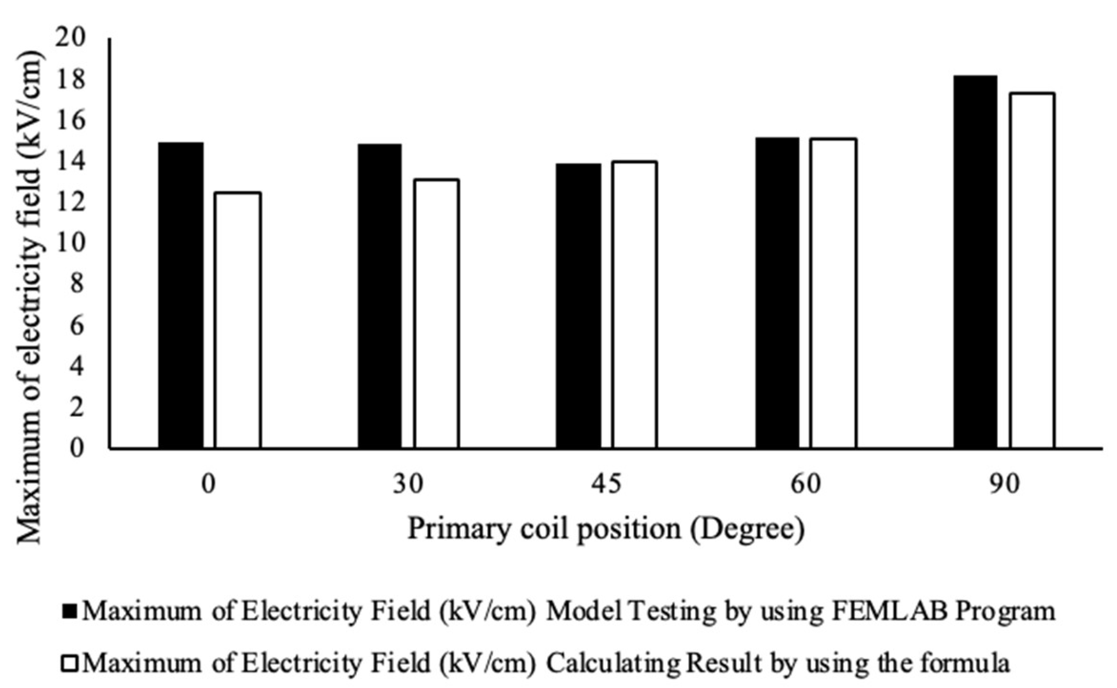
According to the result of tesla transformer testing and the electricity field model that design in the putting of low and high voltage coil of tesla transformer 3 times. It would consider choosing by using the distribution impulse by indicate it in the adjustment atmosphere. Primary coil at the same point which is binding 8 rounds of primary coil at the difference angle and from the table 3 and table 4. It would see that at this point the distribution voltage, would almost the same amount with the model at 120 kV 120 kHz and it is the amount of rounding of primary coil Lp that close to the high amount from the model. According to the comparing, it can conclude that to put the primary coil (Lp) from the floor at the angle. It is the internal voltage and high electricity field stress that has the most suitable than another model.
5. Conclusion
This paper present analysis of electric field distribution on primary side of windings of high frequency and voltage transformers with variables characteristics. To study the effect high voltage side of transformer, induce and high frequency for finding suitable dimension. It would start in determining the transformer is external impulse and frequency. The characters of coil induce (the suitable dimension in putting the low voltage coil Lp in the several positions and the model amount that using FEMLAB. The amounts that receive from simulation, would use for comparing analyst with the result of test that get from high voltage transformer and high frequency which was created.) The analysis in the several parameters, it could be link that to put the Lp coil in the suitable angle, it should be at 60 angle according this research.
Author Contributions
Conceptualization, S.N. and N.R.; Methodology, S.N. and N.R.; Validation, N.R.; Investigation, S.N. and N.R.; Writing—original draft, S.N.; Writing—review & editing, N.R. and S.N. All authors have read and agreed to the published version of the manuscript.
Funding
This research received no external funding.
Data Availability Statement
The study's original contributions are included within the article, and any further inquiries can be directed to the corresponding authors.
Acknowledgments
The authors would like to express his sincere thanks to the Rajamangala University of Technology Phra Nakhon (RMUTP), Thailand for their support.
Conflicts of Interest
The authors declare no conflicts of interest.
References
- Denicolai, M. Tesla Transformer for Experimentation and Research; Helsinki University of Technology: Espoo, Finland,, 2001. [Google Scholar]
- Abbasi, A.; Khanzade, M. H. Analysis of Dual Resonant Solid State Tesla Transformer. International Journal of Modern Engineering Research (IJMER) 2013, 3, 3456–3460. [Google Scholar]
- Tanwar, N.; Kumar, M.R.; Naidu, R.C. Design of Solid State Tesla Coil With Music Playback Functionality. IEEE Access 2024, 12, 14285–14297. [Google Scholar] [CrossRef]
- Hernanda, G.N.S.; Asfani, D.A.; Negara, I.M.Y.; Firdaus, M.Y.; Fatahillah, S.B.; Febrianti, A. Comparison of insulation testing in laboratory using solid-state-based tesla high-frequency voltage generation. International Journal of Innovative Computing, Information and Control 2023, 19, 1265–1279. [Google Scholar]
- woratipromma, S. Study and Analysis of a Design and Construction of Solid State Tesla Transformer Rated 100kV 150 kHz. Master of Engineering, Dept. Elect. Eng., Rajamangala University of Technology Thanyaburi,, Pathum Thani, Thailand, 2014. [Google Scholar]
- Rana, M.S.; Pandit, A.K. Design and Construction of a Tesla Transformer by using Microwave Oven Transfer for Experimentation. Innovative Systems Design and Engineering 2014, 5, 15–22. [Google Scholar]
- Tesla, N. Apparatus for Transmitting Electrical Energy. US Patent No. 1119732 1914. [Google Scholar]
- Lantharthong, T.; Nedphograw, S.; Hiranvarodom, S.; Apiratikul, P. Analysis of Electric field and Modeling Design of High Voltage Cable terminators for PD Testing Using SF6 Insulator. In Proceedings of the International Conference on Electrical Engineering 2008, Okinawa, Japan, 6–10 July 2008. [Google Scholar]
- Plangklang, B.; Apiratikul, P.; Phumkittipich, K. Development of Low-Cost Tesla Transformer for High Performance Testing 115 kV Line Post Insulator. Journal of Engineering, RMUTT 2010, 8, 69–78. [Google Scholar]
- Plangklang, B.; Apiratikul, P.; Boonchiam, P. A Low-Cost High Performance Tesla Transformer for testing 115 kV Line Post Insulator. Proceedings of 2006 International Conference on Power System Technology, Chongqing, China, 22–26 October 2006. [Google Scholar]
- Craven, R.M. A study of secondary winding designs for the two-coil Tesla transformer. Ph.D. dissertation, Dept. Elect. Eng., Loughborough Univ., United Kingdom, 2014. [Google Scholar]
- Jana, S.; Biswas, P.K.; Babu, T.S.; Alhelou, H.H. An Improved Parametric Method for Selecting Different Types of Tesla Transformer Primary Coil to Construct an Artificial Lightning Simulator. IEEE Access 2023, 11, 22174–22186. [Google Scholar] [CrossRef]
- Pongsathit, W.; Yutthagowith, P.; Limcharoen, W. Solid state tesla transformer for flashover test on suspension insulators. Proceedings of 2017 International Symposium on Electrical Insulating Materials (ISEIM), Toyohashi, Japan, 11–15 September 2017. [Google Scholar]
- Nedphograw, S. High Voltage Engineering, Rajamangala University of Technology Phra Nakhon, 2018.
- Sangsa-ard, S. High Voltage Engineering. Edition 2, Chulalongkorn University, 1985.
- Thongkeaw, S.; Nedphograw, S.; Plangklang, B.; Apiratikul, P. The Analysis of high-Voltage Electric Field Stress in Lp and Ls coils of Tesla Transformer for studying the efficiency design. Proceedings of IAENG International Conference on Electrical Engineering (ICEE'08); 2008. [Google Scholar]
Figure 1.
Transformer of Tesla circuit.
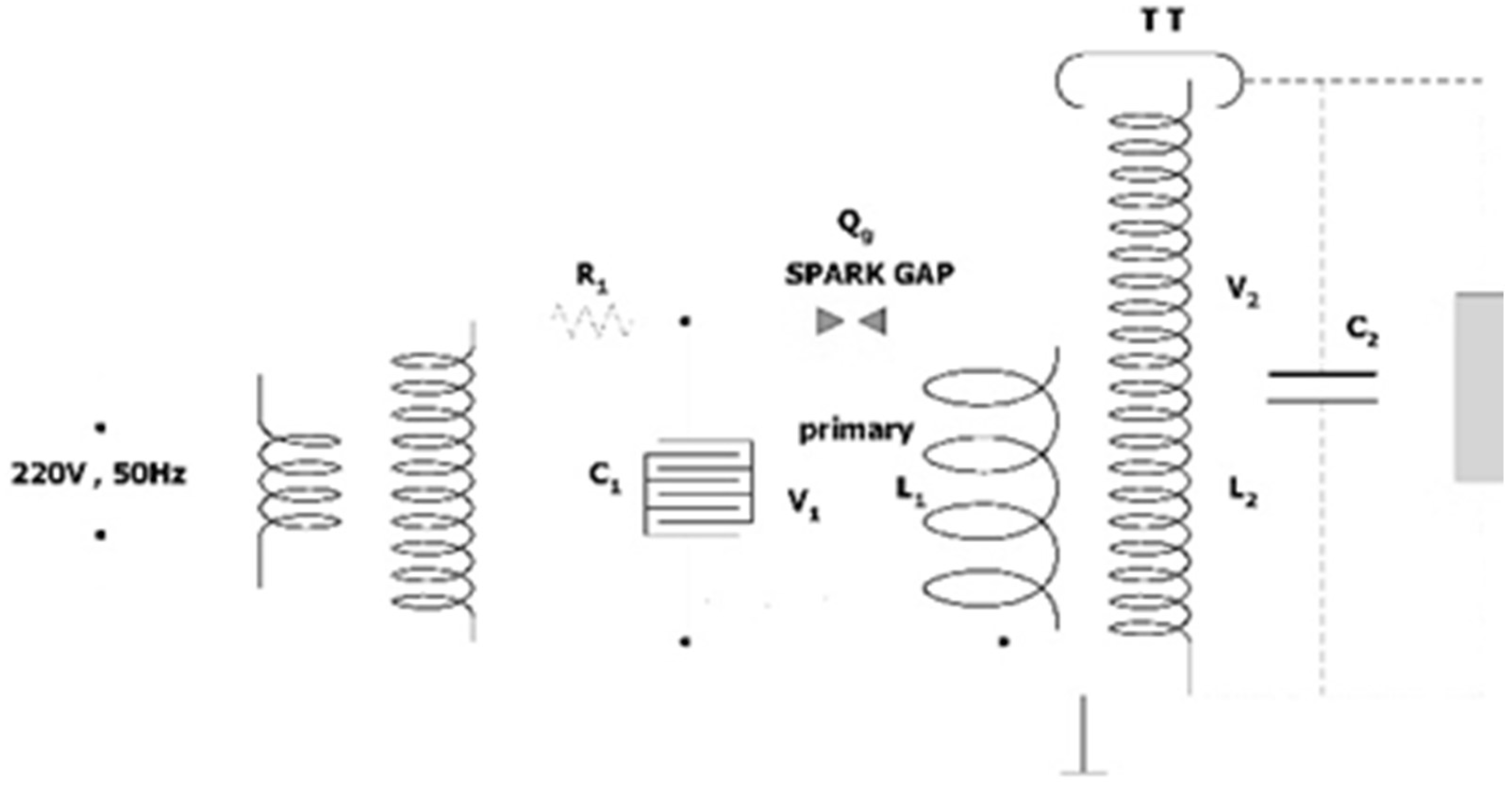
Figure 5.
The model of electricity filed at the low voltage coil in the angle 90 degree from the floor which would have the amount of electricity field maximum equal to 20.99 kV/cm at the beginning of high voltage coil (1st dimension).
Figure 5.
The model of electricity filed at the low voltage coil in the angle 90 degree from the floor which would have the amount of electricity field maximum equal to 20.99 kV/cm at the beginning of high voltage coil (1st dimension).
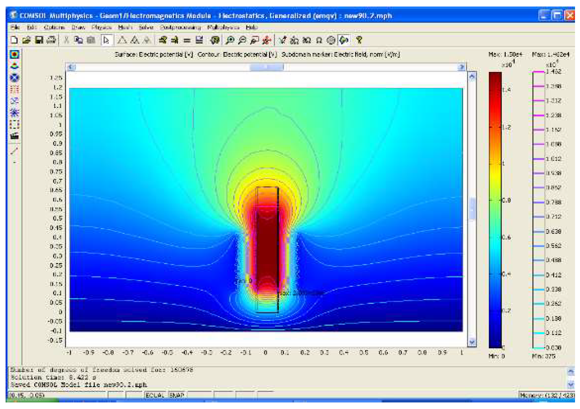
Figure 6.
The result of model of electricity field distribution at the low voltage at the angle 60 degree from the floor. It would have electricity field maximum equal to 15.20 kV/cm at the beginning of high voltage coil (2nd dimension).
Figure 6.
The result of model of electricity field distribution at the low voltage at the angle 60 degree from the floor. It would have electricity field maximum equal to 15.20 kV/cm at the beginning of high voltage coil (2nd dimension).
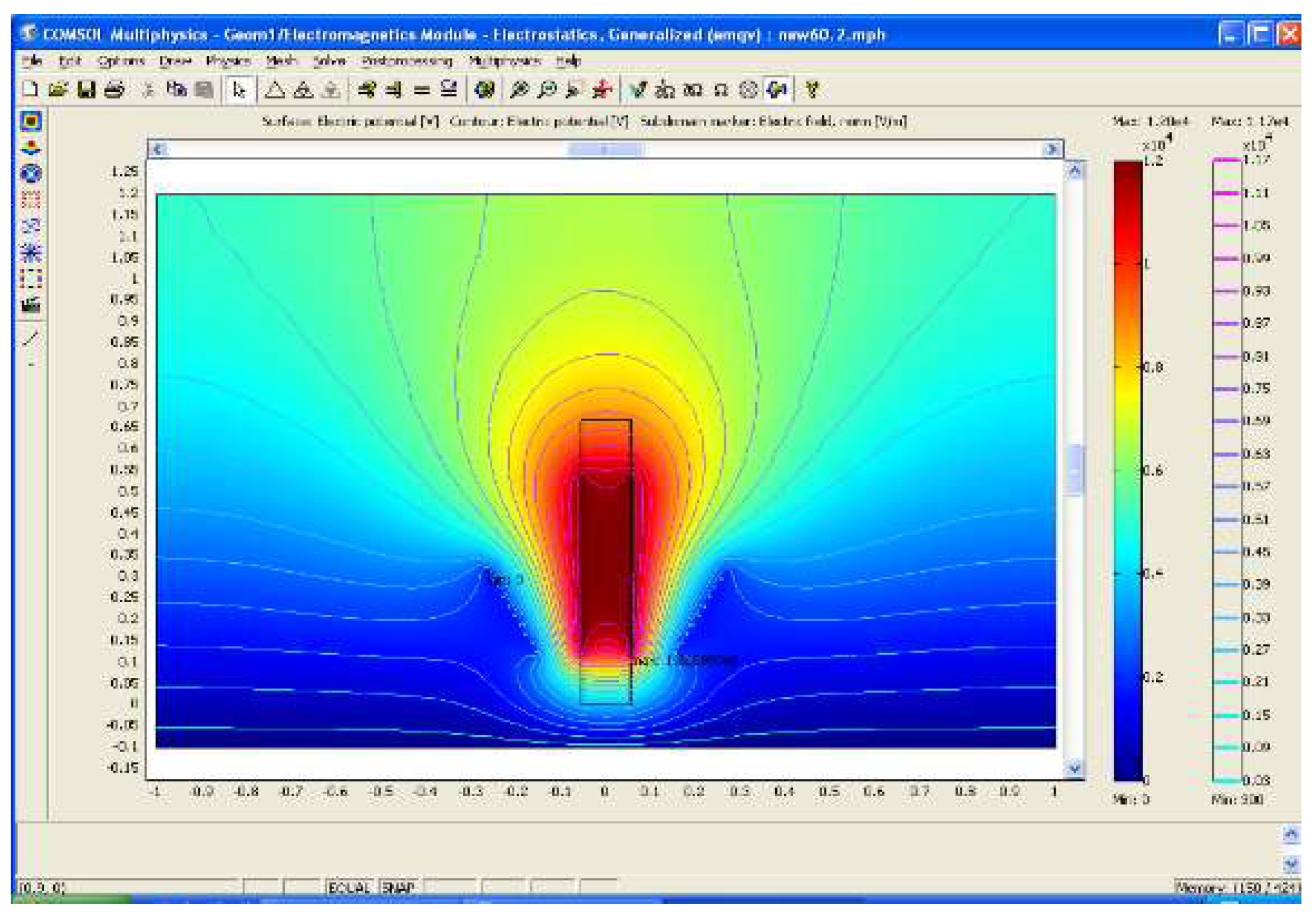
Figure 7.
The result of model of electricity field distribution at the low voltage at the angle 45 degree from the floor. It would have electricity field maximum equal to 13.95 kV/cm at the beginning of high voltage coil (3rd dimension).
Figure 7.
The result of model of electricity field distribution at the low voltage at the angle 45 degree from the floor. It would have electricity field maximum equal to 13.95 kV/cm at the beginning of high voltage coil (3rd dimension).
Figure 8.
The result of model of electricity field distribution at the low voltage at the angle 30 degree from the floor. It would have electricity field maximum equal to 14.91 kV/cm at the beginning of high voltage (4th dimension).
Figure 8.
The result of model of electricity field distribution at the low voltage at the angle 30 degree from the floor. It would have electricity field maximum equal to 14.91 kV/cm at the beginning of high voltage (4th dimension).
Figure 9.
The result of model of electricity field distribution at the low voltage at the angle 0 degree from the floor. It would have electricity field maximum equal to 14.99 kV/cm high voltage of beginning (5th dimension).
Figure 9.
The result of model of electricity field distribution at the low voltage at the angle 0 degree from the floor. It would have electricity field maximum equal to 14.99 kV/cm high voltage of beginning (5th dimension).

Figure 10.
The result of model of electricity field distribution at the low voltage at the angle 90 degree from the floor. It would expand the distance between the Lp and Ls coil from the previous 4 inch to be 5.5 inch., which would have the electricity field amount maximum equal to 18.23 kV/cm. high voltage of beginning (6th dimension).
Figure 16.
Comparing of voltage flow out of putting primary coil.
Disclaimer/Publisher’s Note: The statements, opinions and data contained in all publications are solely those of the individual author(s) and contributor(s) and not of MDPI and/or the editor(s). MDPI and/or the editor(s) disclaim responsibility for any injury to people or property resulting from any ideas, methods, instructions or products referred to in the content. |
© 2024 by the authors. Licensee MDPI, Basel, Switzerland. This article is an open access article distributed under the terms and conditions of the Creative Commons Attribution (CC BY) license (http://creativecommons.org/licenses/by/4.0/).
Copyright: This open access article is published under a Creative Commons CC BY 4.0 license, which permit the free download, distribution, and reuse, provided that the author and preprint are cited in any reuse.


