1. Introduction
Aerostatic bearings use a throttle to regulate external pressurized gas, forming a lubricating gas film on the bearing surface [
1]. With gas film thickness typically in the micron, nanometer, or even sub-nanometer range, aerostatic bearing systems theoretically enable ultra-precise support and rotation. These bearings are widely used in ultra-precision machining, semiconductor equipment, and microgravity simulation [
2]. However, the extremely low viscosity of gas—approximately 1/5000 of fluid viscosity—limits the load capacity and stiffness of aerostatic bearings, restricting their application in heavy-load, high-speed conditions.
Researchers have conducted comprehensive studies on the enhancement of bearing performance through surface microstructures, specifically pressure-equalizing grooves. Guido Belforte et al. compared the static performance of conventional flat and annular groove aerostatic thrust bearings, finding that annular grooves significantly improved the load capacity and stiffness of the aerostatic bearing, particularly under smaller gas film thickness conditions [
3]. Li et al.demonstrated the effectiveness of micro-grooves in improving bearing dynamic stability, showing that they enhance fluid dynamic effects within the bearing clearance [
4]. Chen et al. found that rectangular cross-section uniform grooves exhibited better load capacity and stiffness compared to circular cross-section uniform grooves under certain conditions, particularly when the groove area is small or the eccentricity is high. Bearings achieved optimal load capacity and stiffness when the axial groove length was between 1/4 and 1/2 of the bearing length [
5,
6]. Hong et al. showed that fishbone groove structures effectively suppressed bearing whirl and reduced contact wear risks when the eccentricity was below 0.4 or above 0.62, improving the operational stability of hydraulic suspension micropumps [
7]. Song et al. found that increasing the groove angle beyond 45° had a limited effect on the stability enhancement of aerostatic bearings [
8]. Zhang et al. designed linear, extended, and X-shaped pressure-equalizing grooves on the working surface of gas journal guide rails in ultra-precision micro-machines, finding that the extended grooves exhibited the best load-bearing performance [
9]. Cui et al. pointed out that optimization typically involves parameters such as groove width, depth, and spacing, as well as the positioning of holes and grooves, to improve static and dynamic characteristics of the bearing. Under high gas pressure supply conditions, adding micro-groove structures in the eccentric direction significantly improved the load capacity and stiffness of the bearing, albeit with increased gas flow.The layout direction of micro-groove holes has a significant impact on static characteristics: axial micro-groove holes provide higher load capacity and stiffness with lower gas flow, while circumferential micro-groove holes offer lower load capacity and stiffness but higher gas flow [
10].
The above studies indicate that under low-speed or zero-speed conditions, optimizing the type, layout, and structural parameters of pressure-equalizing grooves can further improve the working characteristics of aerostatic bearings. However, the load-bearing mechanism of aerostatic bearings with pressure-equalizing grooves differ between low- and high-speed ranges. At high-speed rotating bearings, an eccentric distance between the rotor axis and the bearing's geometric center creates a wedge-shaped space, which generates dynamic pressure effect, causing the aerostatic bearing to operate in a mixed state of static and dynamic pressure effect. Su et al. found that the rotational effect significantly affects the load-bearing capacity of dynamic-static pressure mixed bearings, especially when the eccentricity exceeds 0.85. Higher rotational speeds enhance dynamic pressure effects and increase load capacity, but at very high speeds, uneven pressure distribution can reduce stability [
11]. J. Bouyer et al. pointed out that the dynamic-static mixed pressure mode can effectively improve the load capacity and stability of aerostatic bearings, especially in applications involving high loads, high speeds, or frequent startups [
12]. De Pellegrin et al. examined the impact of static pressure grooves on mixed static-dynamic pressure bearings and found that groove depth and shape significantly influence load capacity [
13]. Gao et al. demonstrated that under rotational speeds exceeding 100,000 r/min and low supply pressures, fishbone groove designs significantly improve the performance of ultra-high-speed aerostatic bearings. Groove depth and length were identified as critical factors affecting load capacity, with the geometric parameters of fishbone grooves showing nonlinear dependencies [
14]. Stanev. et al. optimized the design of external pressure bearings with fishbone grooves, achieving excellent spindle performance at speeds exceeding 3.0 ×10⁶DN, limited only by the maximum rotor speed [
15].Schlums et al. studied air-lubricated corrugated bearings for high-speed rotating shafts, showing that optimized geometrical parameters, such as groove inclination angles and depth ratios, are crucial for achieving high-speed stability thresholds [
16].
The load-bearing mechanism of mixed static and dynamic pressure effects in aerostatic bearings under high-speed conditions remains underexplored and lacks a comprehensive theoretical framework. This study leverages gas lubrication theory and the SST k-ω turbulence model, accounting for gas compressibility, to characterize the global gas film flow field in AGSTABs. It investigates how parameters such as eccentricity, groove width ratio, and groove depth ratio influence the static and dynamic pressure effects within the gas film at high speeds, aiming to provide a deeper understanding of the load-bearing mechanism in AGSTABs.
2. Methods
2.1. Flow Field and Mesh Model of Annular Groove Gas Journal Bearing
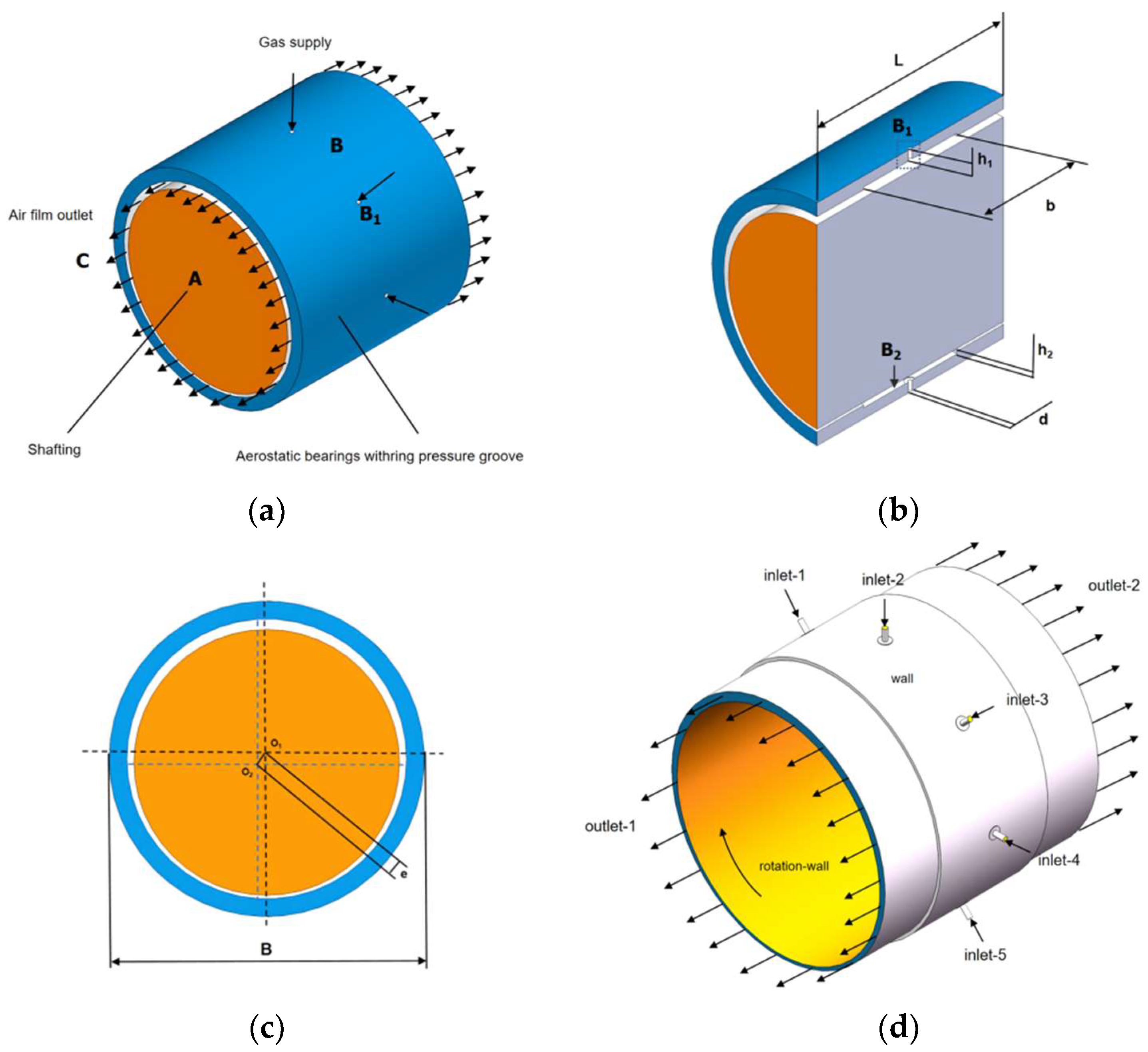
Figure 1 shows the geometric structure of the AGSTABs shaft system. In
Figure 1(a), A represents the rotor, B represents the AGSTABs, and C represents the gas film. In
Figure 1(b)–(c), B
1 represents the throttling holes, B
2 represents the annular groove, L is the bearing length, B is the bearing diameter, e is the eccentricity, d is the diameter of the throttling holes, h
1 is the length of the throttling holes, b is the width of the annular groove, and h
2 is the depth of the annular groove. Gas enters the throttling holes B
1, flows through the pressure-equalizing chamber, the annular groove B
2, the clearance between the bearing and rotor, and finally exits through the outlet holes. As shown in
Figure 1(d), the boundary conditions for the gas film flow field of AGSTABs in numerical solution include inlet, outlet, wall surfaces, and rotating wall surface.
Table 1 lists the structural dimensions of AGSTABs.
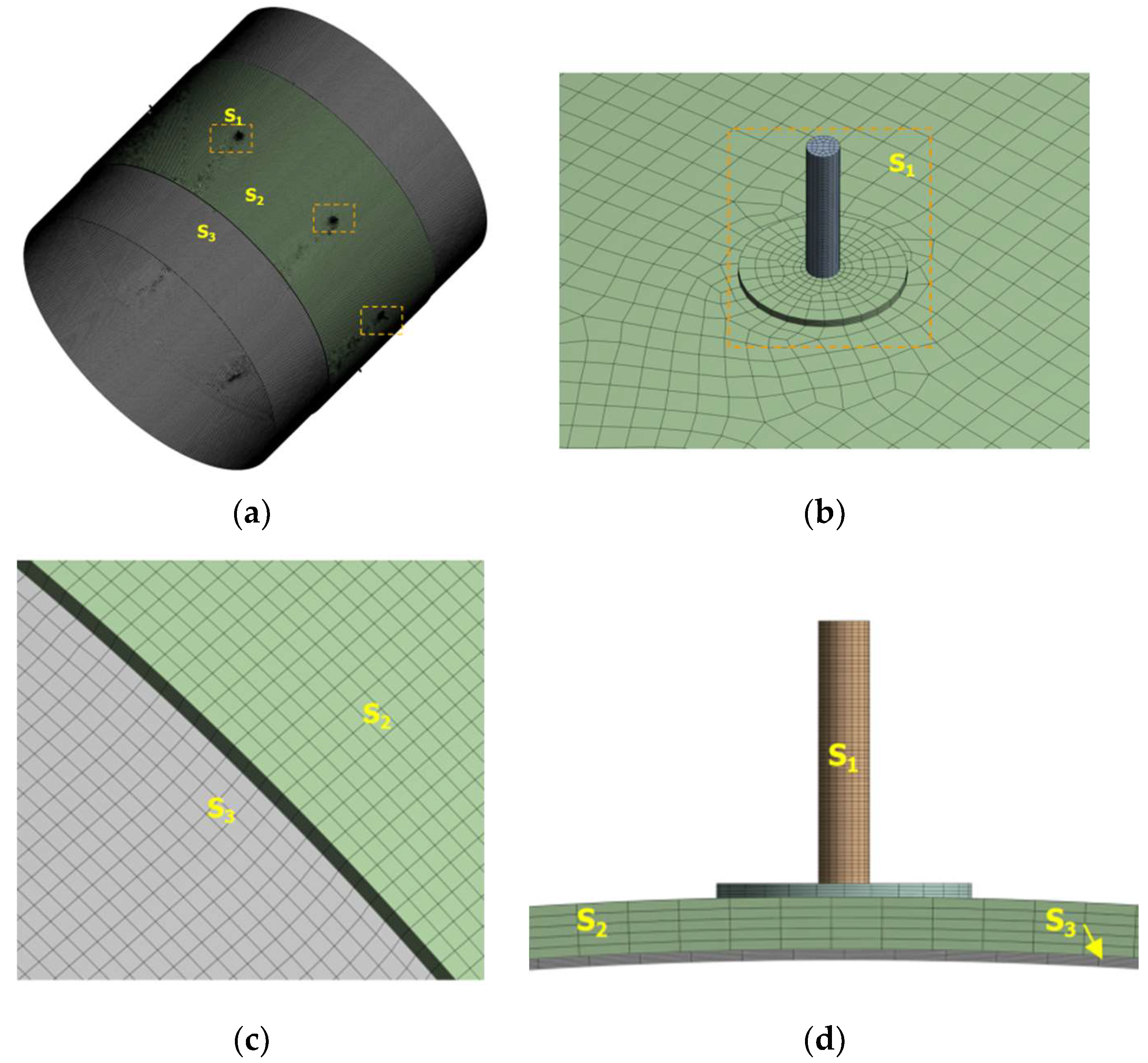
Figure 2 shows the discretization process of the gas film flow field geometry for AGSTABs. As depicted in
Figure 2(a), the geometry is divided into three sections using the ANSYS DesignModeler: the throttling holes and pressure-equalizing chamber (S1), the annular groove gas film (S2), and the main gas film (S3). All contact surfaces are set as shared nodes. The model is then imported into the ANSYS Mesh module for meshing.Following a mesh independence study, the global mesh size is set to 150 µm. The S1 region is meshed using a multi-zone method, while the S2 and S3 regions are meshed using the thin sweeping method. The S1 and S2 regions are further divided into 5 layers along the thickness direction. The final mesh contains approximately 1 million elements, with 99.8% of the mesh elements achieving an orthogonal quality of 1.
2.2. Shear Stress Transport k−ω Model
At high rotational speeds, the flow field within the gas film of an annular groove aerostatic bearing becomes highly complex and turbulent, characterized by multi-scale vortices, significant velocity fluctuations, and pressure pulsations. Solving such flow fields using Direct Numerical Simulation (DNS) is extremely time-intensive and requires substantial computational resources. The SST k-ω turbulence model offers a more practical solution by applying Reynolds-averaged processing to the Navier-Stokes equations at a manageable computational cost. By incorporating additional equations for turbulent kinetic energy (k) and specific dissipation rate (ω), the model separates turbulent fluctuations, enabling accurate prediction of flow separation and turbulence transition phenomena.The SST k-ω model involves two main components: the Reynolds-averaged equations (including the continuity, momentum, and energy equations) and the k-ω equations. The tensor forms of these equations are as follows:
Equation (1) is continuity equation.Where
is the density of the ideal gas,
is time,
u is the time-averaged velocity of the flow field.
Equation (2) is momentum equation.Where p is the time-averaged pressure of the flow field,
is the reynolds stress term,
represents dynamic viscosity,
ui uj represent the velocity tensor component along each coordinate axis,
Si is the source term.
Equation (3) is energy equation.Where
s is the gas thermal conductivity,
cp is the specific heat capacity,
T is the gas temperature,
ST is the viscous dissipation term.
Equations (4) and (5) are the turbulent kinetic energy (k) transport equation and the specific dissipation rate (ω) equation, respectively.Where is the turbulent viscosity, Pk and Pw are the production terms for for k and ω, YK Yw are the divergence terms for k and ω respectively; Dw is the cross-diffusion term, are the Prandtl numbers for k and ω.
Table 2 provides the parameters for the case studies, including the width ratio, depth ratio, and eccentricity of the pressure-equalizing groove. The SST k−ω turbulence model is solved using the SIMPLEC algorithm to obtain the pressure distribution within the gas film flow field of AGSTABs. The gas film flow field medium is set as an ideal gas, the supply pressure (P
S) is 0.4MPa, the outlet pressure (P
o) is 0 Pa, and the ambient pressure (P
e) is 0 Pa. The rotational wall speed is
v.
k and ω are discretized using a second-order upwind scheme. During the iterative solution of the algebraic equations, the convergence residuals for continuity, velocity, and energy are all set to 1×10
−4.
3. Results and Discussion
3.1. Analysis of the Mechanism of Dynamic-Static Pressure Effects
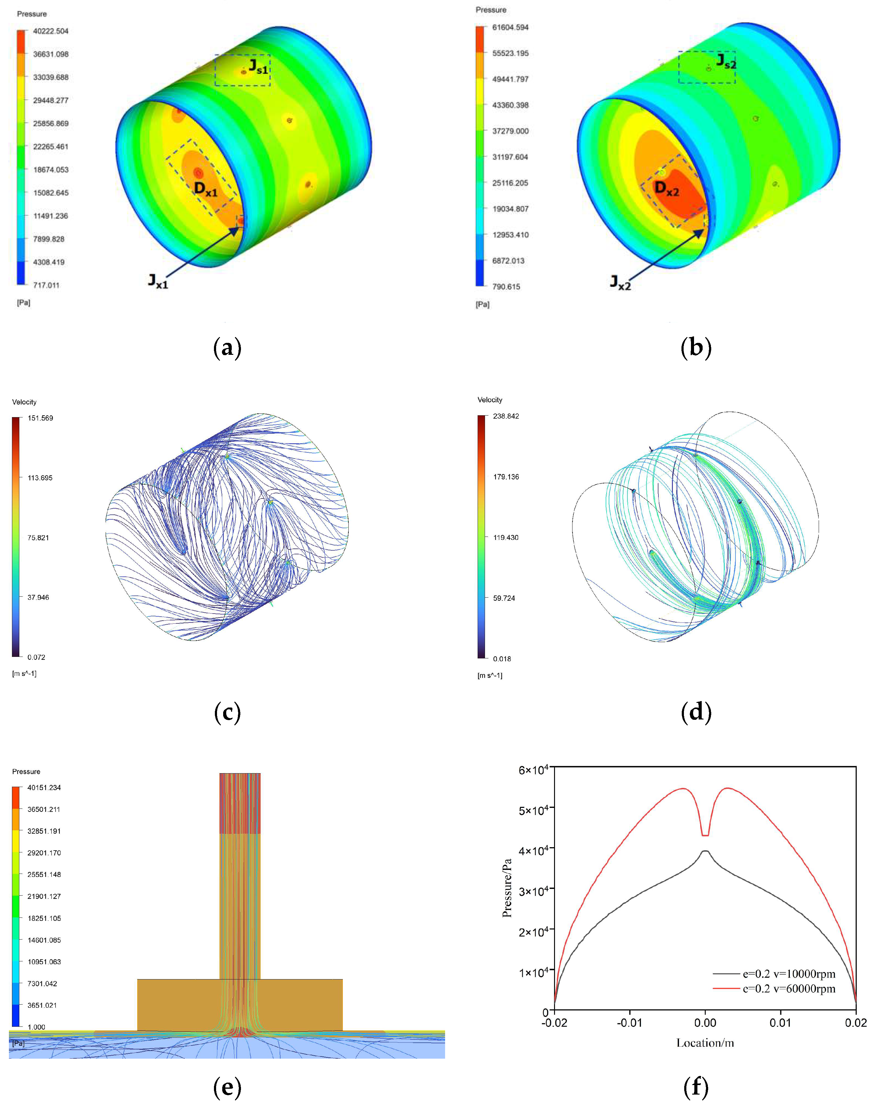
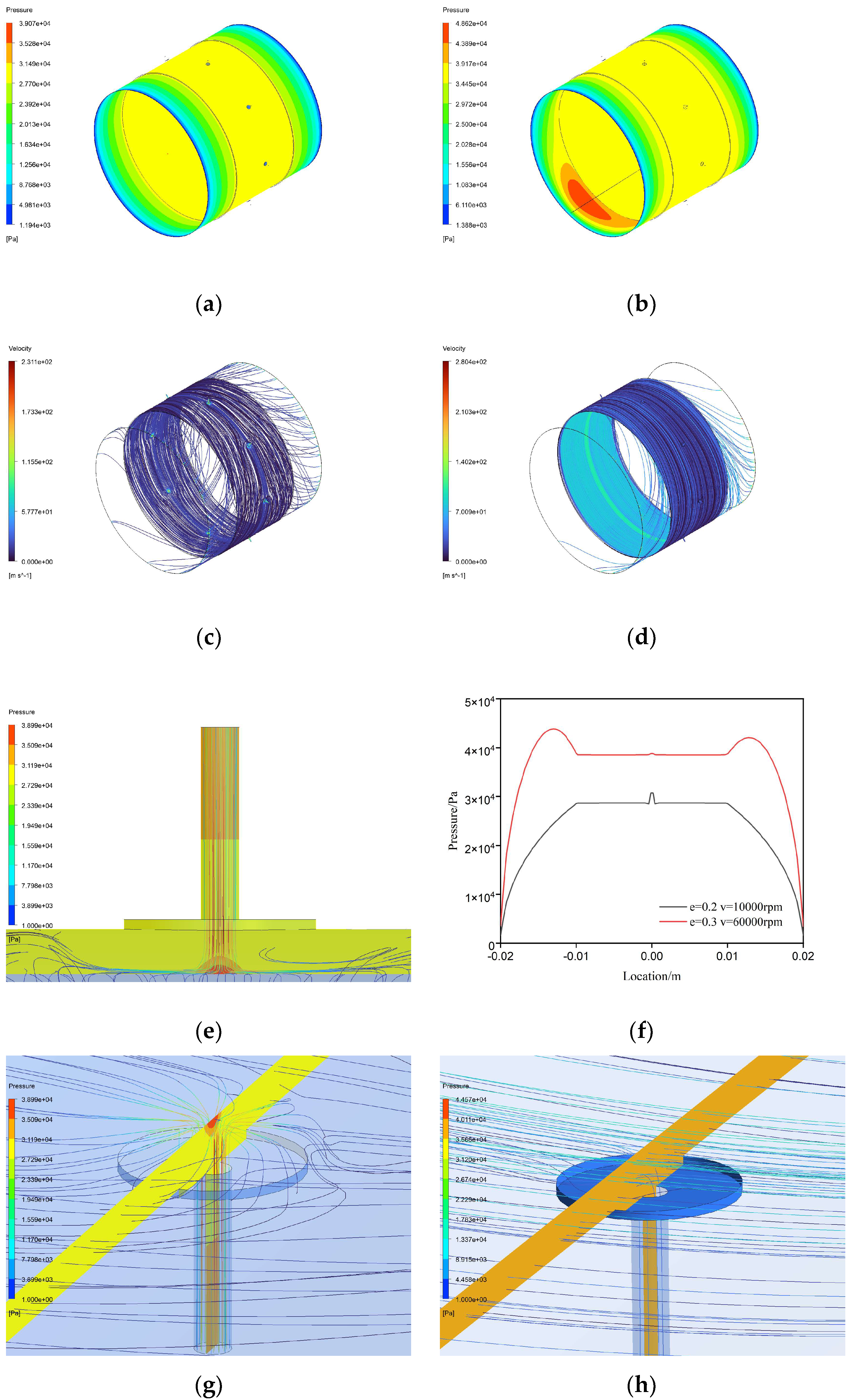
Figure 3 illustrates the pressure distribution and flow characteristics of the gas film flow field in STAB. As shown in Figures 3(a) and (b), the gas film pressure flow field demonstrates a mixed state of static and dynamic pressure effects. The dynamic pressure load-bearing region is concentrated in the area of minimum gas film thickness, denoted as D
x1 or D
x2, while the static pressure load-bearing region is more widespread, encompassing the gas diffusion areas driven by the pressure gradient between the supply and outlet boundaries.In
Figure 3 (f), at a rotational speed of 10,000 rpm, the pressure profile in the mixed region of STAB exhibits an "A"-shaped local high-pressure peak due to the static pressure effect of the small holes, alongside symmetrical "M"-shaped high-pressure peaks generated by the dynamic pressure effect. At 60,000 rpm, the "A"-shaped local high-pressure peak disappears, while the "M"-shaped high-pressure peaks increase significantly.
As shown in
Figure 3 (e), due to the throttling effect, the pressurized gas accelerates through the small holes. Upon entering the bearing clearance, it impacts the wall at high speeds due to inertia, causing abrupt changes in velocity and direction, which form an "A"-shaped local high-pressure region. Comparing Figures 3 (c) and (d), as rotational speed increases, the high-speed gas exiting the small holes is subjected to strong centrifugal forces, pulling it into the rotational flow field and reducing its likelihood of wall impact. Consequently, at 60,000 rpm, the "A"-shaped local high pressure characteristic becomes less pronounced. The "M"-shaped high-pressure results from the spatial overlap of the "A"-shaped local high-pressure field and the pressure field formed by dynamic pressure effects. The formation of dynamic pressure effects depends on the acceleration and compression of gas in the wedge-shaped clearance. The combined effects of gas viscosity, inertia, velocity gradients, and geometry generate dynamic load-bearing capacity. A higher velocity gradient enhances the dynamic pressure effect. Comparing Figures 3 (a) and (b), the dynamic pressure peak in the D
x2 region is significantly higher than in the D
x1 region, resulting in a notable increase in the "M"-shaped high-pressure peaks in
Figure 3 (i).
Furthermore, the enhancement of dynamic pressure effects intensifies the occurrence of vortices and backflow within the flow field. As shown in
Figure 3 (h), noticeable vortices and backflow are present in the J
x2 and W
x regions. At high rotational speeds, as depicted in
Figure 3 (b), the pressure peak in the dynamic pressure region reaches approximately 60,000 Pa, while the supply pressure in the J
x2 region and other throttling holes is 40,000 Pa. This creates a reverse pressure gradient opposing the rotor's rotation, which gradually weakens along the dynamic pressure region in the opposite rotational direction, resulting in backflow in the Wx region. The backflow gas, driven by inertia, further impacts the gas exiting the supply holes in the J
x2 region, generating vortices and backflow in J
x2.
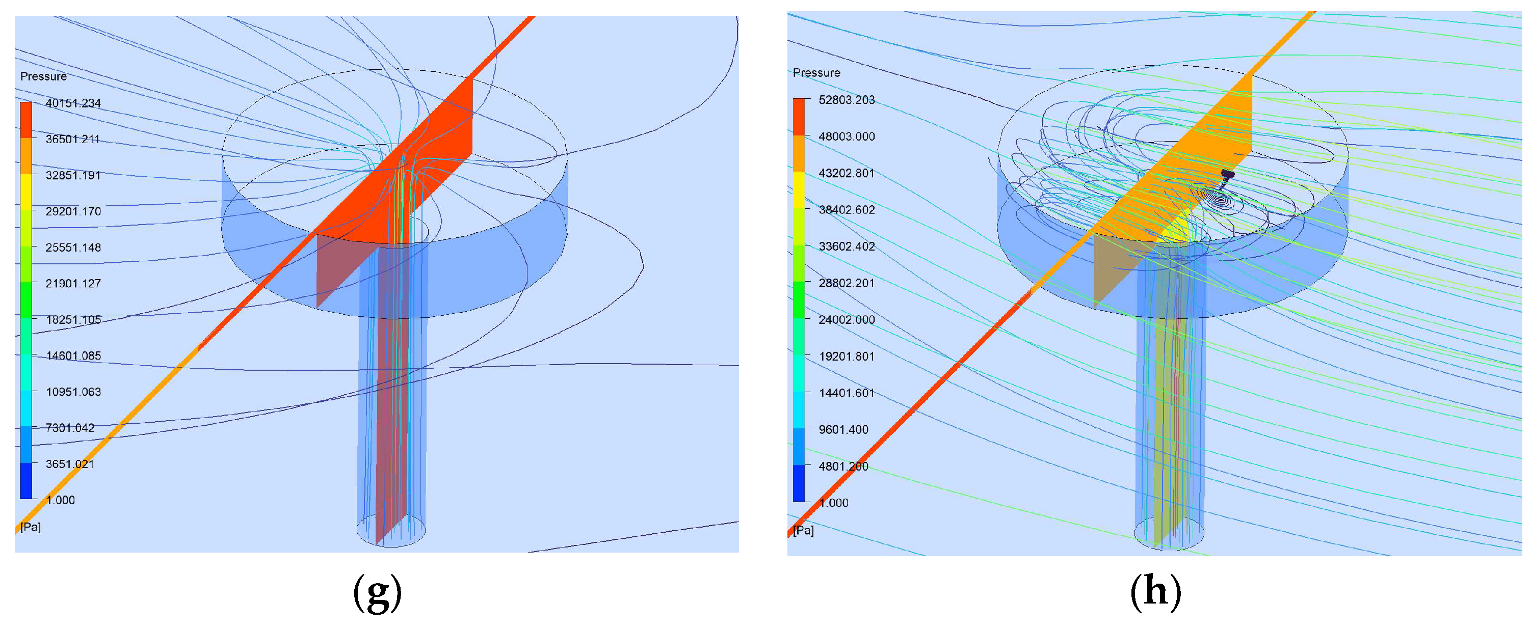
The annular groove structure optimizes the mixed static-dynamic pressure load-bearing mechanism of aerostatic bearings at high rotational speeds. As shown in Figures 4 (a) and (b), under a rotational speed of 10,000 rpm, the pressure flow field of AGSTAB is in a pure static pressure state, exhibiting a broader and more stable pressure distribution within the annular groove. At 60,000 rpm, the flow field transitions to a mixed state of static and dynamic pressure effects. As depicted in
Figure 4 (f), the pressure profile in the static pressure load-bearing region of AGSTAB not only exhibits the "A"-shaped local high-pressure characteristic but also features a "flat-line" constant-pressure zone. This indicates that the static pressure effect in gas film flow field is generated by the dual throttling action of the small holes and the annular groove, resulting in a superior static pressure effect for the annular groove aerostatic bearing. At 60,000 rpm, the "A"-shaped local high-pressure zone nearly disappears, while the "flat-line" constant pressure increases from 28,000 Pa to 35,000 Pa. The dynamic pressure effect region forms a narrower, symmetric "M"-shaped high-pressure distribution. This demonstrates that increasing rotational speed enhances the secondary throttling effect of the annular groove but suppresses the throttling effect of the small holes.
Comparing Figures 3 (c) and Figures 4 (c)-(d), at high rotational speeds, centrifugal and inertial forces cause the gas exiting the throttling holes of AGSTAB to predominantly circulate within the annular groove, with only a small portion exiting through the outlet. This creates a secondary throttling effect in the annular groove, resulting in the "flat-line" constant pressure. Within the annular groove, the spatial scale in the thickness direction of the groove is much larger than the thickness of the gas film. Therefore, at high speeds, dynamic pressure effects are less likely to form within the groove, allowing the throttling effect of the annular groove to fully develop. This increases the secondary throttling effect, leading to a rise in the "flat-line" constant pressure.As shown in
Figure 4 (a) and (b), the load-bearing mechanism of static and dynamic pressure effects in the AGSTAB differs from that of STAB. In the STAB gas film flow field, the static and dynamic pressure fields overlap, while the annular groove structure separates the load-bearing regions of the two effects, minimizing mutual interference. Additionally, the annular groove aerostatic bearing effectively suppresses vortex and backflow phenomena.
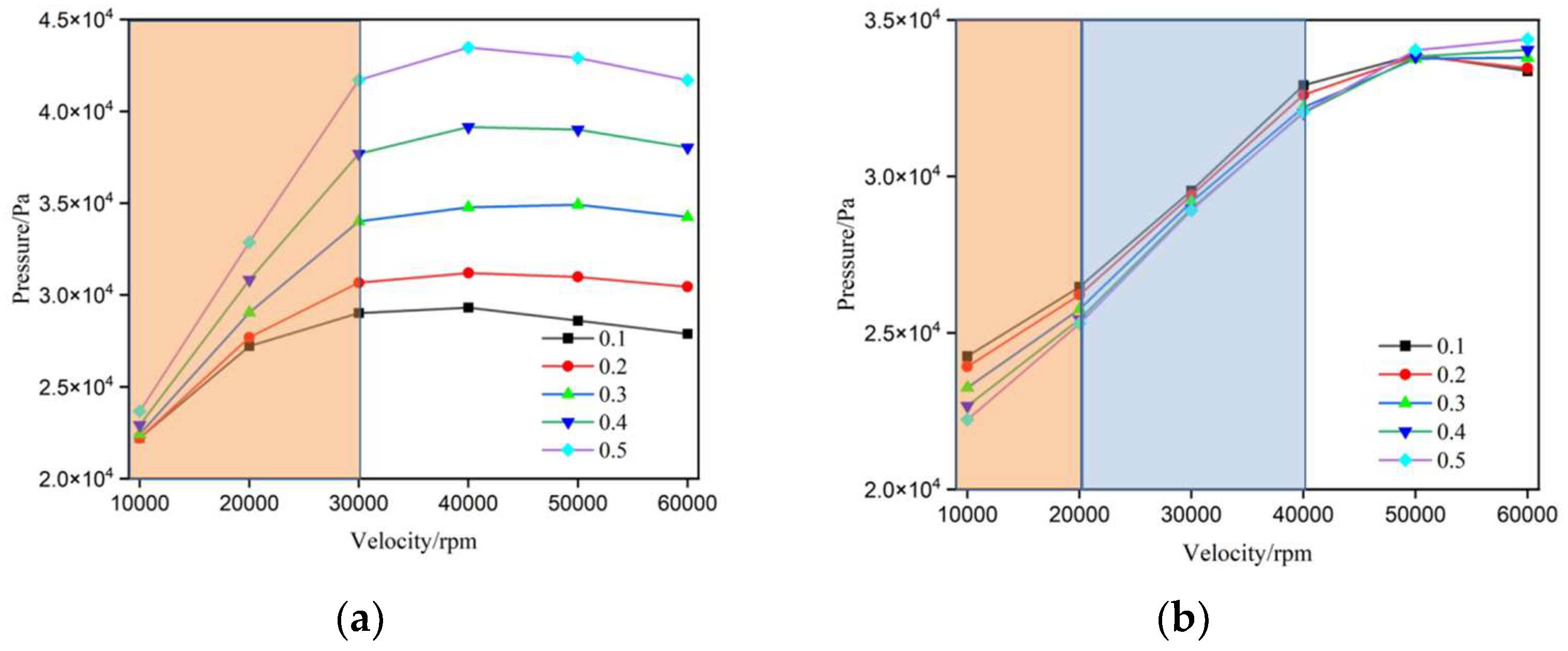
3.2. Eccentricity
Figure 5 shows the relationship between average load capacity and rotational speed for annular groove and non-groove small-hole throttling aerostatic bearings under different eccentricity conditions. For both bearings, as the rotational speed increases from 10,000 rpm to 30,000 rpm, the average load capacity of the gas film increases significantly across all eccentricity levels, demonstrating that higher rotational speeds enhance the load-bearing capacity of STABs. At the same rotational speed, larger eccentricities result in higher average load capacities, while smaller eccentricities produce relatively lower load capacities. This trend indicating that greater eccentricity significantly improves the gas film load-capcaity, regardless of the presence of an annular groove.For eccentricities between 0.1 and 0.3, the AGSTAB outperforms the non-groove design. At an eccentricity of 0.1, the annular groove aerostatic bearing achieves the highest average load capacity, with a 20% improvement over the non-groove STAB. However, for eccentricities between 0.3 and 0.5, the traditional STABs surpasses the annular groove design in average load capacity, reaching its maximum at an eccentricity of 0.5. While the average load capacity of the traditional STABs plateaus at around 30,000 rpm, the AGSTABs continues to show increasing load capacity with rising speeds. This clearly demonstrates that the annular groove structure effectively raises the stability threshold for high-speed operation in aerostatic bearings.
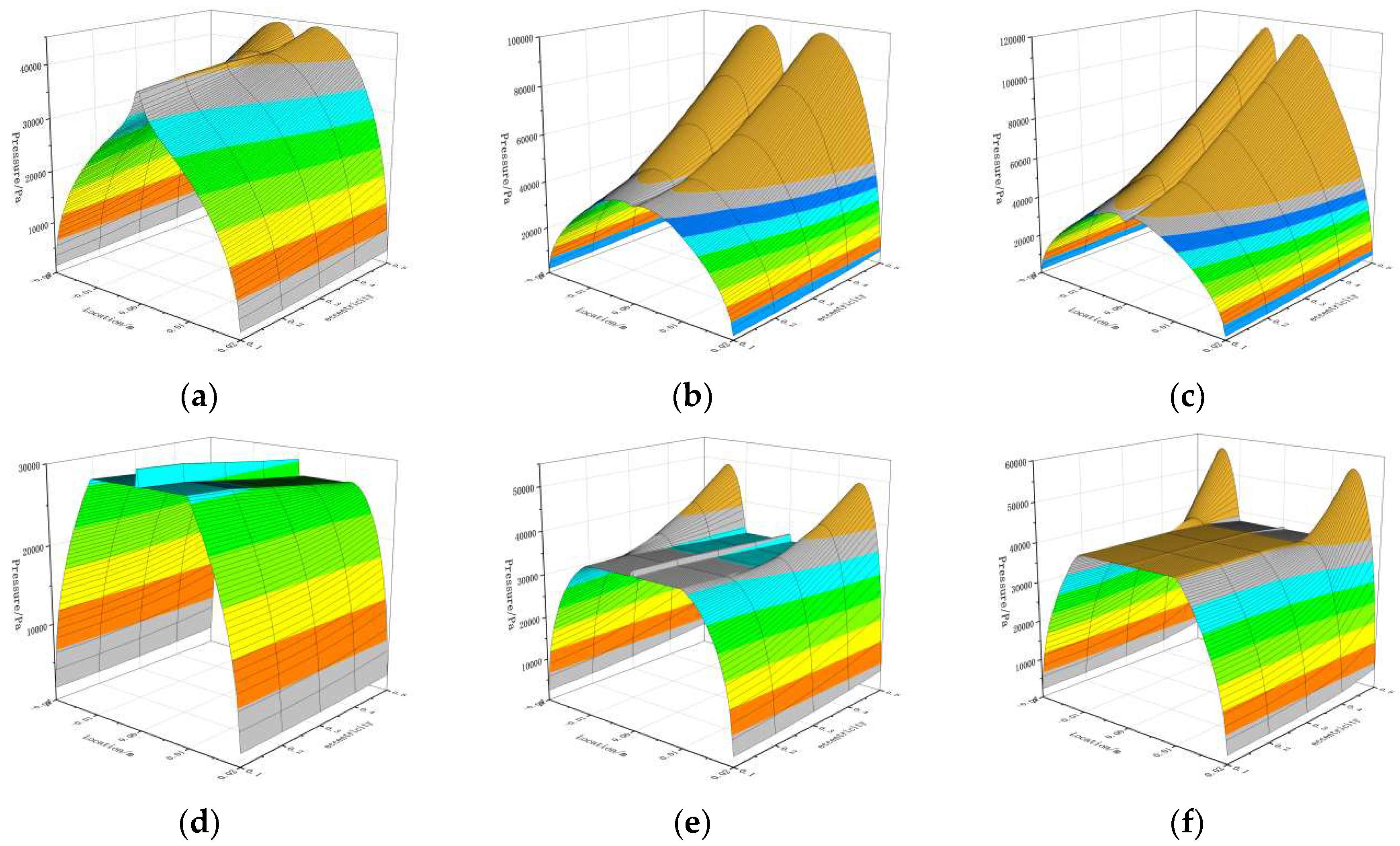
Figure 6 shows the pressure distribution at the thinnest gas film position in STABs and AGSTABs under different eccentricities as the rotational speed varies. Comparing Figure (a) and Figure (d), at 10,000 rpm, the gas film flow fields of both STABs and AGSTABs are dominated by static pressure effects for eccentricities between 0.1 and 0.3. For eccentricities between 0.4 and 0.5, the "A"-shaped local high-pressure characteristic generated by small-hole throttling disappears, while the "M"-shaped dynamic pressure peak increases. Meanwhile, the gas film flow field of AGSTAB remains in a pure static pressure state, with the pressure curve showing both the "A"-shaped local high-pressure and a "flat-line" constant-pressure feature.Comparing
Figure 6 (b) and (e), at 30,000 rpm, the "A"-shaped local high-pressure characteristic in the gas film pressure curve of STABs. As the eccentricity increases from 0.1 to 0.5, the "M"-shaped dynamic pressure peak rises sharply. In contrast, the gas film flow field of the annular groove throttling aerostatic bearing remains in a static pressure state for eccentricities between 0.1 and 0.2. For eccentricities between 0.2 and 0.5, the gas film flow field transitions to a mixed state of static and dynamic pressure effects, with the narrow "M"-shaped dynamic pressure peak increasing from 3MPa to 4.8MPa.
Figure 6 (c) and
Figure 6 (e) show trends similar to
Figure 6 (b) and
Figure 6 (e).
In summary, for both types of bearings, increasing eccentricity enhances the dynamic pressure effects in the flow field while weakening the static pressure effects of small-hole throttling. For the same eccentricity, AGSTABs require higher rotational speeds to generate dynamic pressure effects.
3.3. Width Ratio
Figure 7 illustrates the variation in average load capacity with rotational speed for annular groove aerostatic bearings with different width ratios. For all width ratio conditions, the average load capacity increases significantly as the rotational speed rises from 10,000 rpm to 40,000 rpm. However, beyond 40,000 rpm, the load capacity for certain width ratios (0.1, 0.3, 0.5) starts to decline.At the same rotational speed, narrower width ratios (0.1 and 0.3) result in a notable increase in load capacity, while higher width ratios (0.7 and 0.9) show only marginal improvements. This indicates that narrower grooves are more effective at concentrating pressure, thereby substantially enhancing load capacity.As the width ratio increases, the rotational speed at which the peak average load capacity occurs also rises. For bearings with width ratios of 0.1, 0.3, and 0.5, the average load capacity peaks at 30,000 rpm, 40,000 rpm, and 60,000 rpm, respectively. These findings suggest that the design of annular groove aerostatic bearings should account for the operational speed range to select the most suitable width ratio for achieving optimal load-bearing performance.
Figure 8 depicts the pressure variation at the thinnest point of the gas film in annular groove aerostatic bearings with different width ratios. In
Figure 8 (a), as the width ratio increases from 0.1 to 0.9, the "A"-shaped local high pressure decreases from 3.5 MPa to 1.5 MPa, and the "flat-line" constant pressure drops from 3.3 MPa to 1.4 MPa. During this range, the gas film flow field is predominantly governed by static pressure effects. As shown in
Figure 8 (b), as the width ratio varies from 0.1 to 0.9, the gas film flow field transitions into a mixed state of static and dynamic pressure effects. The "A"-shaped local high pressure decreases from 3.8 MPa to 1.7 MPa, the "flat-line" constant pressure drops from 3.5 MPa to 1.6 MPa, and the narrow "M"-shaped dynamic pressure peak declines from 6.3 MPa to 1.7 MPa. In
Figure 8 (c), the trends in the gas film flow field closely align with those observed in
Figure 8 (b).
In conclusion, the width ratio significantly influences the relative contributions of static and dynamic pressure effects to the overall load-bearing capacity. As the width ratio increases, the peak pressure and contribution of dynamic pressure effects gradually decrease, while the contributions of small-hole throttling and the annular groove structure also diminish. Higher width ratios result in a greater reliance on static pressure effects for load bearing, but they also reduce the throttling efficiency of the annular groove.
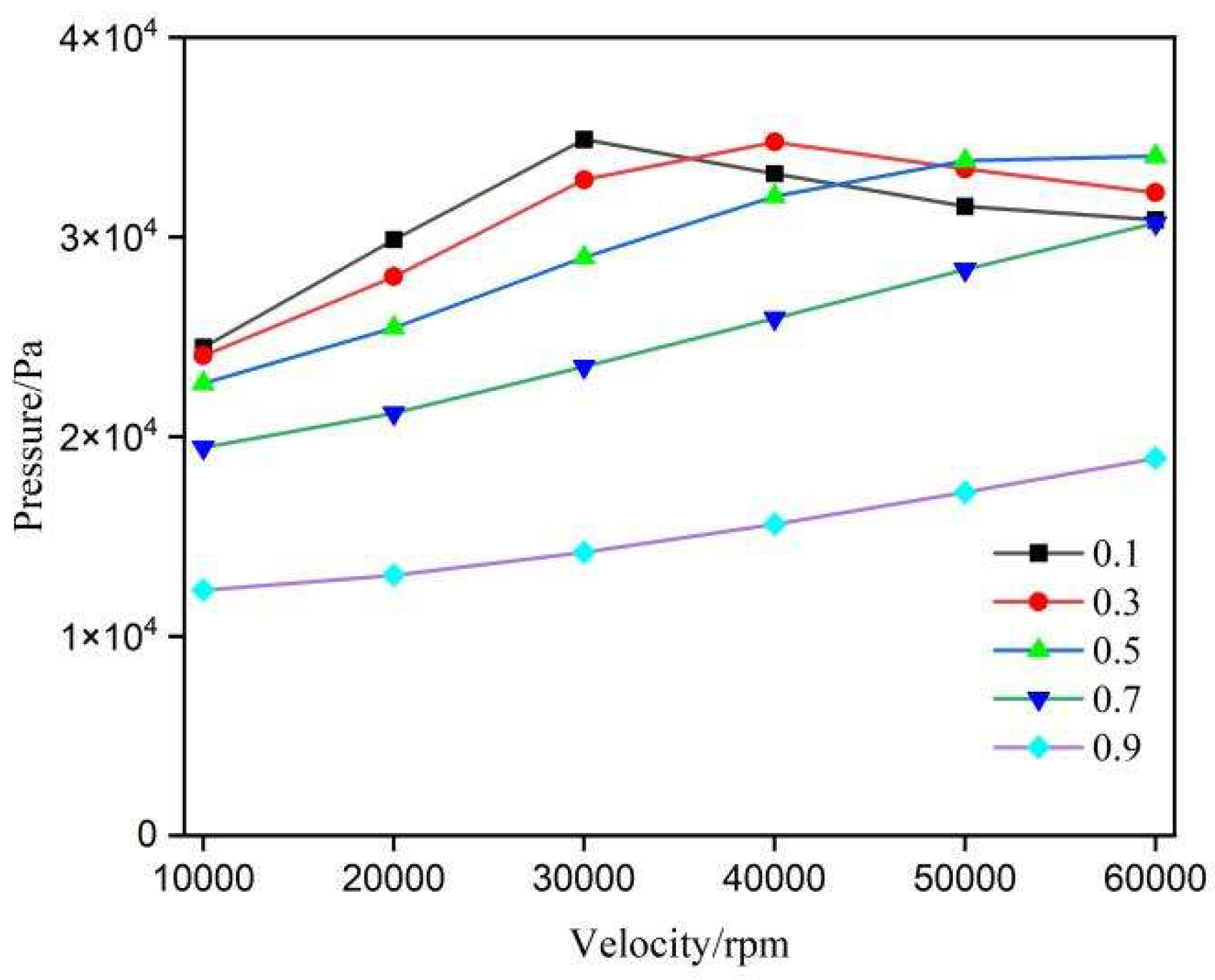
3.4. Depth Ratio
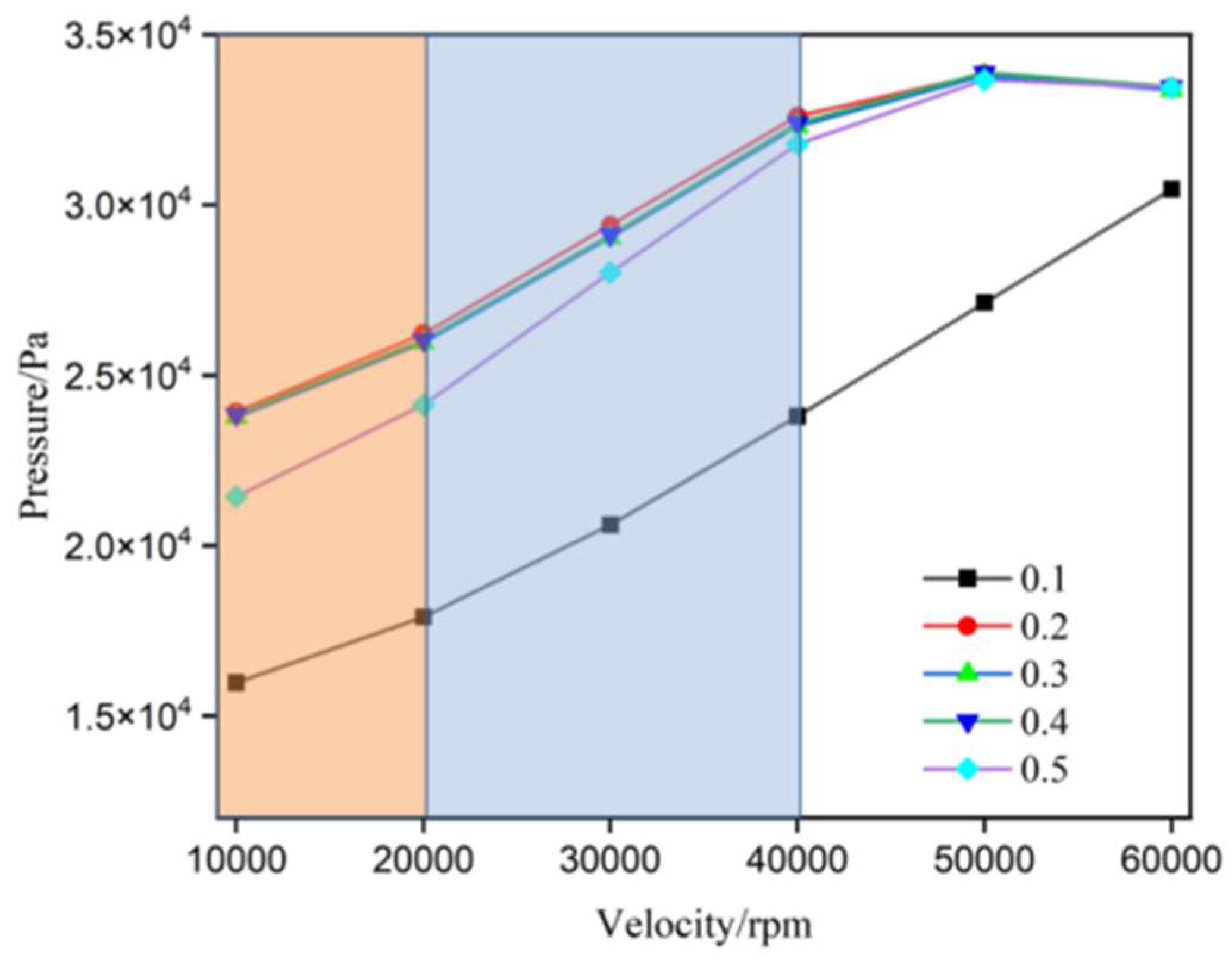
Figure 9 shows the relationship between the average load capacity and rotational speed for gas journal bearings with different annular groove depth ratios. Overall, as the rotational speed increases from 10,000 rpm to 60,000 rpm, the average load capacity exhibits a significant upward trend across all depth ratio conditions. Between 10,000 rpm and 30,000 rpm, the load capacity increases notably with the depth ratio, particularly when the depth ratio rises from 0.1 to 0.4, resulting in an increase of over 60%. However, from 40,000 rpm to 60,000 rpm, the differences in load capacity across various depth ratios gradually diminish, with the curves converging. This is especially true for depth ratios above 0.2, where the variations in load capacity become negligible. These results indicate that at high rotational speeds, the influence of annular groove depth on load capacity weakens.
Figure 10 depicts the pressure variation at the thinnest gas film location for AGSTABs with different depth ratios. As shown in
Figure 9 (a), the flow field remains in a pure static pressure state across all rotational speed ranges. At 10,000 rpm, as the depth ratio increases from 0.1 to 0.2, the "flat-line" constant pressure rises from 1.8 MPa to 2.7 MPa. When the depth ratio increases further from 0.2 to 0.4, the "flat-line" constant pressure continues to rise from 2.7 MPa to 2.8 MPa, though the overall change is minimal. The trends observed in Figures (b) and (c) are consistent with this pattern.
In summary, selecting an appropriate depth ratio can enhance the static pressure effects in the flow field without amplifying the generation of dynamic pressure effects.
4. Conclusions
This study leverages gas lubrication theory and the SST k−ω model, combined with ANSYS Fluent, to compare the load-bearing mechanisms of static and dynamic pressure effects in the flow fields of AGSTABs and STABs at rotational speeds of 10,000 rpm and 60,000 rpm. The effects of eccentricity, width ratio, and depth ratio on static and dynamic pressure performance were analyzed, leading to the following conclusions:
Annular groove aerostatic bearings effectively optimize the mixed load-bearing mechanism of static and dynamic pressure effects in high-speed gas film flow fields. Secondary annular groove throttling significantly enhances static pressure effects. Moreover, the annular groove structure spatially separates static and dynamic pressure zones, reducing the intensity of reverse pressure gradients in the flow field. This minimizes the occurrence of vortices and backflow, improving the high-speed stability of annular groove aerostatic bearings.
Larger eccentricities significantly improve the load-bearing capacity of both AGSTABs and STABs. For eccentricities between 0.1 and 0.3, AGSTABs demonstrate superior performance. High eccentricity and rotational speeds amplify dynamic pressure effects in the flow field but weaken the small-hole throttling effect. However, the secondary throttling effect of the annular groove remains largely unaffected. At the same eccentricity, AGSTABs require higher rotational speeds to develop dynamic pressure effects.
The width ratio affects the contribution of static and dynamic pressure effects to the overall load-bearing capacity. As the width ratio increases, the peak pressure and the proportion of dynamic pressure effects decrease, along with the intensity of static pressure effects from both small-hole throttling and annular groove secondary throttling.
Depth ratio has a minimal effect on dynamic pressure performance. However, selecting an appropriate depth ratio enhances static pressure effects in the flow field, resulting in a modest improvement in the load-bearing capacity of the gas film in AGSTABs.
In conclusion, annular groove aerostatic bearings exhibit superior performance at high speeds by enhancing static pressure effects, segregating static and dynamic pressure zones, and reducing flow instabilities. Optimizing parameters such as eccentricity, width ratio, and depth ratio is critical for achieving optimal bearing performance.
Author Contributions
methodology, W.S.; software, W.S.; validation, W.S., P.C. and M.L.; formal analysis, W.S.; investigation, W.S., D.W.;writing—original draft preparation, W.S.; supervision, C.S.; project administration, J.Z.; funding acquisition, C.S. All authors have read and agreed to the published version of the manuscript.
Funding
This research was funded by National Key Research and Development Plan: Research and Application Demonstration of the Key Technical System for National Quality Infrastructure in the High-Speed Precision Sliding Bearing Industry, grant number 2021YFF0603000.
Data Availability Statement
The original data presented in the study are available from the corresponding author upon reasonable request.
Acknowledgments
The authors thank the China Productivity Center for Machinery for their financial support and would like to thank the editors and anonymous reviewers for their valuable comments and suggestions.
Conflicts of Interest
Minggui Li was employed by the company China Xinshidai Certification Body. The remaining authors declare that the research was conducted in the absence of any commercial or financial relationships that could be construed as a potential conflict of interest.
References
- Rowe W B. Hydrostatic and hybrid bearing design[J]. Tribology International, 1983,17(6):353.
- Colombo F, Lentini L, Raparelli T, et al. Special Issue “Gas Bearings: Modelling, Design and Applications”: Applied Sciences[Z]. 2022: 12.
- Belforte G, Colombo F, Raparelli T, et al. Comparison between grooved and plane aerostatic thrust bearings: static performance[J]. Meccanica (Milan), 2011,46(3):547-555. [CrossRef]
- Li P, Li J, Shi Z, et al. Effects of manufacturing errors and micro-groove surfaces on the static and dynamic characteristics of water-lubricated bearings[J]. Physica scripta, 2023,98(9):95903. [CrossRef]
- Chen X, Mills J K, Bao G. Static performance of the aerostatic journal bearing with grooves[J]. Proceedings of the Institution of Mechanical Engineers. Part J, Journal of engineering tribology, 2020,234(7):1114-1130.
- Chen X, Mills J K, Shi K, et al. Numerical investigation on the static performance of aerostatic journal bearings with different pocket shapes by the finite-element method[J]. Proceedings of the Institution of Mechanical Engineers. Part J, Journal of engineering tribology, 2021,235(9):1897-1911.
- Hong T, Xing G, Zuo H, et al. Increasing operational stability of journal bearing in hydraulic suspension micro-pump by herringbone grooved structure[J]. Science China. Technological sciences, 2024,67(3):853-862. [CrossRef]
- Song L, Yuan G, Zhang H, et al. The Stability of Spiral-Grooved Air Journal Bearings in Ultrahigh Speeds[J]. Materials (Basel), 2022,15(5). [CrossRef]
- Zhang H, Guan X, Wang T, et al. Influence of Pressure-Equalizing Groove on Static Load Performance of Aerostatic Guideway[J]. Journal of applied fluid mechanics, 2023,16(5):992-1004. [CrossRef]
- Cui W, Li S, Zhu B, et al. Research on the influence of a micro-groove-orifice structure and its layout form on the static characteristics of aerostatic journal bearings under a high gas supply pressure[J]. Advances in mechanical engineering, 2023,15(2).
- Su J C T, Lie K N. Rotation effects on hybrid hydrostatichydrodynamic journal bearings[J]. Industrial lubrication and tribology, 2001,53(6):261-269. [CrossRef]
- Bouyer J, Wodtke M, Fillon M. Experimental research on a hydrodynamic thrust bearing with hydrostatic lift pockets: Influence of lubrication modes on bearing performance[J]. Tribology international, 2022,165:107253. [CrossRef]
- De Pellegrin D V, Hargreaves D J. An isoviscous, isothermal model investigating the influence of hydrostatic recesses on a spring-supported tilting pad thrust bearing[J]. Tribology international, 2012,51:25-35. [CrossRef]
- Gao S, Shi Y, Xu L, et al. Investigation on influences of herringbone grooves for the aerostatic journal bearings applied to ultra-high-speed spindles[J]. Proceedings of the Institution of Mechanical Engineers. Part C, Journal of mechanical engineering science, 2019,233(16):5795-5812. [CrossRef]
- Stanev P T, Wardle F, Corbett J. Investigation of grooved hybrid air bearing performance[J]. Proceedings of the Institution of Mechanical Engineers. Part K, Journal of multi-body dynamics, 2004,218(2):95-106.
- Schlums H, Hühne C, Sinapius M. Design of a Herringbone-Grooved Bearing for Application in an Electrically Driven Air Compressor[J]. Machines (Basel), 2022,10(8):662. [CrossRef]
Figure 1.
Geometric structure of AGSTABs shaft system. (a) Complete assembly of the AGSTABs and rotor; (b) Axial Cross-Section of the Assembly Between the AGSTABs and Rotor; (c) Radial Cross-Section of the Assembly Between the AGSTABs and Rotor; (d) Boundary conditions of the gas film flow field for the AGSTABs.
Figure 2.
Discretization process of the gas film flow field geometry model for AGSTABs. (a) Geometry division and meshing of the flow field.; (b) Coincident node meshing.; (c) Local mesh in the region connecting S2 and S3; (d) Meshing of regions S1, S2, and S3.
Figure 2.
Discretization process of the gas film flow field geometry model for AGSTABs. (a) Geometry division and meshing of the flow field.; (b) Coincident node meshing.; (c) Local mesh in the region connecting S2 and S3; (d) Meshing of regions S1, S2, and S3.
Figure 3.
Flow field characteristics of STABs. (a) Pressure distribution of STABs flow field at 10,000 RPM; (b) Pressure distribution of STABs flow field at 60,000 RPM; (c) Streamline characteristics of STABs flow field at 10,000 RPM; (d) Streamline characteristics of STABs flow field at 60,000 RPM; (e) Orifice throttling effect; (f) Pressure curve of the flow field at the Hmin position; (g) Vortices in the ATABs flow field at 10,000 RPM; (h) Vortices and backflow in the STABs flow field at 60,000 RPM.
Figure 4.
Flow field characteristics of annular-groove gas-static bearings. (a) Pressure distribution of AGSTABs flow field at 10,000 RPM; (b) Pressure distribution of AGSTABs flow field at 60,000 RPM; (c) Streamline characteristics of AGSTABs flow field at 10,000 RPM; (d) Streamline characteristics of AGSTABs flow field at 60,000 RPM; (e) Orifice throttling effect; (f) Pressure curve of the flow field at the Hmin position; (g) Vortices in the AGSTABs flow field at 10,000 RPM; (h) Vortices in the AGSTABs flow field at 60,000 RPM.
Figure 5.
Average gas film load capacity of aerostatic bearings under different eccentricity conditions. (a) STABs; (b) AGSTABs.
Figure 5.
Average gas film load capacity of aerostatic bearings under different eccentricity conditions. (a) STABs; (b) AGSTABs.
Figure 6.
Pressure distribution curves at the minimum gas film thickness position of aerostatic bearings under different eccentricity conditions. (a) 10,000 RPM-STABs; (b) 30,000 RPM-STABs; (c) 60,000 RPM-STABs; (d) 10,000 RPM-AGSTABs; (e) 30,000 RPM-AGSTABs; (f) 60,000 RPM-AGST- ABs.
Figure 6.
Pressure distribution curves at the minimum gas film thickness position of aerostatic bearings under different eccentricity conditions. (a) 10,000 RPM-STABs; (b) 30,000 RPM-STABs; (c) 60,000 RPM-STABs; (d) 10,000 RPM-AGSTABs; (e) 30,000 RPM-AGSTABs; (f) 60,000 RPM-AGST- ABs.
Figure 7.
Average gas film load capacity of AGSTABs under different width ratios.
Figure 7.
Average gas film load capacity of AGSTABs under different width ratios.
Figure 8.
Pressure distribution curves at the minimum gas film thickness position of aerostatic bearings under different width ratios. (a) 10,000 RPM-AGSTABs; (b) 30,000 RPM-AGSTABs; (c) 60,000 RPM-AGSTABs.
Figure 8.
Pressure distribution curves at the minimum gas film thickness position of aerostatic bearings under different width ratios. (a) 10,000 RPM-AGSTABs; (b) 30,000 RPM-AGSTABs; (c) 60,000 RPM-AGSTABs.
Figure 9.
Average gas film load capacity of AGSTABs under different depth ratios.
Figure 9.
Average gas film load capacity of AGSTABs under different depth ratios.
Figure 10.
Pressure distribution curves at the minimum gas film thickness position of aerostatic bearings under different different depth ratios. (a) 10,000 RPM-AGSTABs; (b) 30,000 RPM-AGST- ABs; (c) 60,000 RPM-AGSTABs.
Figure 10.
Pressure distribution curves at the minimum gas film thickness position of aerostatic bearings under different different depth ratios. (a) 10,000 RPM-AGSTABs; (b) 30,000 RPM-AGST- ABs; (c) 60,000 RPM-AGSTABs.
Table 1.
Dimensional Parameters of the AGSTAB.
Table 1.
Dimensional Parameters of the AGSTAB.
| Parameter |
Value |
| Bearing Outer Diameter B (mm) |
40 |
| Bearing Length L (mm) |
40 |
| Number of Throttling Holes N |
8 |
| Throttling Hole Length h1 (mm) |
1 |
| Throttling Hole Diameter d (mm) |
0.2 |
| Pressure-equalizing Groove Depth h2 (µm) |
0.1/0.2/0.3/0.4/0.5 |
| Pressure-equalizing Groove Width b (mm) |
4/12/20/28/36 |
Table 2.
Case Parameters.
Table 2.
Case Parameters.
| Parameter |
Value |
| Depth ratio (h2/h1) |
0.1, 0.2, 0.3, 0.4, 0.5 |
| Width ratio (b/B) |
0.1, 0.3, 0.5, 0.7, 0.9 |
| Eccentricity (e/hmin) |
0.1, 0.2, 0.3, 0.4, 0.5 |
| Rotational speed (v,rpm) |
10000, 20000, 30000, 40000, 50000, 60000 |
|
Disclaimer/Publisher’s Note: The statements, opinions and data contained in all publications are solely those of the individual author(s) and contributor(s) and not of MDPI and/or the editor(s). MDPI and/or the editor(s) disclaim responsibility for any injury to people or property resulting from any ideas, methods, instructions or products referred to in the content. |
© 2024 by the authors. Licensee MDPI, Basel, Switzerland. This article is an open access article distributed under the terms and conditions of the Creative Commons Attribution (CC BY) license (http://creativecommons.org/licenses/by/4.0/).