Submitted:
19 November 2024
Posted:
20 November 2024
Read the latest preprint version here
Abstract
Vertical ground source heat pumps are one of the most efficient ways for comfort heating/ cooling. Their effective utilization needs optimization in the borehole heat exchanger length which is a major cost contributing factor. The total length of the borehole piping depends on the heat transfer resistances provided by both the borehole and the surrounding soil. For a typical soil-to-grout thermal conductivity ratio of ≥1, the borehole typically contributes 15-30% to the total resistance, while the soil accounts for the remaining 70-85%. Soil thermal resistance is a function of geographic location and is quite difficult to reduce. Borehole thermal resistance however can be reduced by various practically possible ways. One way to reduce the borehole thermal resistance is by introducing a barrier between the inlet and the outlet legs. Depending on the geometry and the material for the barrier, they can either reduce the thermal short-circuiting between the two legs, improve the heat transfer through the inlet leg or both. This numerical study using FlexPDE, analyses the arrangements for a barrier between the two legs of the U-tube heat exchanger to mitigate the thermal resistance. Implementing these techniques in a conventional U-tube design could lead to a significant reduction in the borehole length.
Keywords:
ground source heat pump
; ground source heat exchanger
; vertical ground source heat pump
; borehole heat exchanger
; heat transfer for ground source heat pump
; borehole thermal resistance
; thermal short-circuiting in borehole heat exchanger
1. Introduction
Closed loop vertical ground source heat pumps are notably widespread for their efficiency and effectiveness compared to other ground source heat pump types like horizontal closed loop, direct exchange, open loop, and surface water ground source heat pumps [1]. One of their key advantages is the compact footprint of the heat exchanger in the form of a borehole, which makes them especially suitable for residential areas with small plots and commercial buildings [1]. They also ensure stable ground temperature and demand minimal pumping energy [1]. However, the system does have drawbacks such requirement for a deep borehole drilling which contributes to a higher cost and challenges related to expertise in borehole drilling and proper implementation [1,2].
Typically, water (or a mixture of water and antifreeze in below-freezing soil conditions) circulates on one side of the ground source heat exchange system, while refrigerant circulates on the other side, directly connected to the heat pump. According to [3], boreholes typically range from 100-150mm in diameter and have depths of 15-120 meters. Borehole length can be further increased to 180m or more if the procedures for deep boreholes are followed. A U-tube containing the circulating fluid is inserted into each borehole, typically made of polyethylene with a diameter of 20-40 mm, although other pipe materials may also be utilized as per [3]. Figure 1 illustrates the U-pipe arrangement.
An alternative to U-tube is coaxial pipe arrangement where a smaller pipe (the inner pipe) is enclosed within a larger outer pipe. The heat transfer fluid can be circulated in two ways. One way is to enter the fluid through the outer pipe (inlet pipe) and return the fluid via inner pipe (outlet pipe). The other flow arrangement is to enter the fluid via inner pipe (inlet pipe) and return the fluid via outer pipe (outlet pipe). Figure 2 illustrates the coaxial pipe arrangements.
Usually the space between the U-tube/ coaxial pipe and the borehole wall is filled with grout, which serves a crucial role in stabilizing the U-tube/ coaxial pipe within the buried system and in preventing water seepage into the borehole. BHX cost (which is mainly the cost of U-pipe, grout and borehole drilling) for GSHP typically accounts for more than 30% of the total cost of the GSHP system [4] Given its significant expense, optimizing this component is vital for enhancing heat transfer efficiency and for harnessing more sustainable energy from the same area of the land.
Increasing the length of the ground loop in a BHX, reduces the approach of BHX defined as the difference between average loop temperature Tf and the initial ground temperature T0. Reducing the thermal resistance between the ground and the circulating fluid enhances the heat transfer, thereby reducing the required length of the heat exchanger for a given approach.
The total thermal resistance consists of two parts: the soil itself and the borehole, which includes grout, pipe material, and the circulating fluid.
Reduction in any of the above two components or both will lead to an improved heat transfer. The heat transfer resistance characteristics of soil vary with geographic location and are generally immutable. Deep soil mixing offers a viable method to lower soil thermal resistance, yet its implementation is expensive and may not be economically feasible across all site conditions and soil types. On the other hand, there are methods to decrease Rb i.e. BHX thermal resistance. Therefore, the overall thermal resistance of the system can be reduced for an enhanced heat transfer by adopting techniques to lower the BHX thermal resistance.
Previous research on the optimization of borehole thermal resistance has investigated the impact of pipe material, borehole diameter, shank spacing, and grout material. Research by Kerma et-al (2024) [5] discusses various geometric factors (shank spacing, borehole size/diameter, borehole depth), grout and soil thermal conductivity for single and double U tube arrangements and then proposes the combined effective measures for heat transfer improvement. Shen et.al (2023) [6]discusses the various influential factors (such as flow rate, inlet temperature, heat extraction rate, length of BHX and backfill material) on the performance of deep U-tube BHX and suggest an optimal control of flow rate. Erol et al. [7] studied various BHE grout materials, including bentonite-based, silica sand-based, and homemade admixtures with graphite. By TRT test, they found that adding just 5% graphite enhances grout thermal conductivity, crucial for optimizing heat transfer efficiency when matched appropriately to ground conductivity.
Liu et al. (2018) [8] conducted a comprehensive study to assess potential cost reductions through enhancements in borehole heat transfer under diverse geological and thermal conditions and revealed that improvements such as enhanced grout and double U-tube loops effectively reduce borehole lengths. The study primarily focuses on installation costs and relies on the simplified geometrical approach of Eskilson’s g-function through commercial software.
Research work is also available on comparison of U-tube with coaxial pipe and a few other arrangements like double U-tube, discussing the thermal behavior of the BHX with these arrangements. Study made by Zanchini et al. [9] showed that in coaxial pipes, the configuration where water flows into the BHX through the outer annular pipe and exits through the inner pipe provides superior thermal performance compared to the opposite arrangement, where inflow occurs through the center or inner pipe and outflow through the outer annular portion. Brown et al. (2023) [10] modelled coaxial, single U-pipe and double U-pipe configurations, finding coaxial pipes exhibiting highest heat transfer rate and lower pressure drop. Harris et al (2022) [Ref. 13] demonstrated that the coaxial BHX configuration is more effective than the double U-pipe design. According to Chen et al. 2010, [11], by using double U-tubes in parallel in BHXs, the heat transfer capacity may increase by over 50% from the single U tube system which could justify the cost increase in installation and pumping energy consumption. Chen et al. 2023 [12] suggest use of VIT (Vacuum Insulated Tube) for coaxial pipe arrangement to prevent thermal short-circuiting. An economic analysis is suggested as the cost of VIT is 5 times more than the cost of un-insulated tubing.
While there is an ample research work available on the comparative study of materials and geometry of the U-tube BHX and its comparison with the other arrangements like coaxial pipes and double U-tube, there is not much research work on segregating the inlet and outlet leg of the U-tube to prevent them from a direct interaction with each other. Al-Chalabi (2013) [13] investigated the effects of introducing obstructions in a U-tube BHX. However, the study did not account for the thickness of the U-tubes, which may have led to overestimated efficiency of the barriers compared to scenarios where tube thickness is considered. Similarly, Ngo et al. (2022) [14] conducted a numerical assessment to evaluate the impact of an insulated barrier between the U-tube legs. While the study provides valuable insights into the effects of Reynolds and Prandtl numbers, it does not address the thermal conductivity of the barrier material, nor does it explore the potential implications of the insulated barrier in greater detail. Additionally, the assumption of laminar flow within the U-tube could increase the risk of thermal short-circuiting, an aspect that warrants further analysis.
Overall, there is a need for a more detailed evaluation of the thermal performance of the barrier, with a specific comparison to a conventional U-tube system. This would allow for a clearer assessment of the barrier's unique contribution. Due to complexity of the BHX geometry, numerical assessment would be more appropriate. Additionally, it would be beneficial to compare these results with other enhancement techniques, such as coaxial pipe arrangements, to offer a broader selection of borehole heat exchanger (BHX) design options.
2. Methods
A traditional single U-tube heat exchanger was numerically assessed and validated for different combinations of shank spacing and grout. A coaxial pipe BHX was assessed to see the improvements in efficiency of the heat transfer in the BHX compared to a traditional single U-tube BHX. Next investigation was to see the effects of different obstructions between the two legs of a U-tube BHX and comparison of the resulting improvement.
Numerical assessment was done on FlexPDE software version 6.51, a finite element model builder and solver.
2.1. Model Assumptions and Governing Equation:
The analysis was performed for a single BHX under steady-state heat transfer. The heat transfer inside the borehole for longer time steps can be considered as steady-state heat transfer within that time step [15]. The lower limit of the time step is 5 times rb2/α. This lower time limit of 5 rb2/α is usually a few hours for different soils and borehole sizes. Similarly, a radial steady-state approximation for the small annulus of the soil near the borehole gives an error of less than 0.3% in determining the resistance of the soil outside the borehole [15]. Thus, for a time efficient model, we conclude that it is appropriate to consider steady-state heat transfer both inside and outside the borehole.
Homogeneous ground condition is considered in the analysis as a simplification assumption [16]. With the assumptions of steady-state heat flow and homogenous ground material, a two-dimensional model can effectively capture the essential heat flow characteristics in the material and is therefore considered for the analysis.
A far-field radius is the radius of influence and beyond it, the temperature of the soil remains un-disturbed [17]. According to study made by Ruan, the soil within 0.5 meters of the borehole reacts to the short-term heat flux from the ground to the fluid. In contrast, the area beyond 0.5 meters is primarily influenced by the long-term net energy input into the ground heat exchange system. After 1 meter from the center of the borehole, there is no significant change in the mean fluid temperature [18]. We therefore have based our analysis for a far-field radius of 1 meter.
No contact resistance, no moisture migration through the soil, homogenous grout & pipe materials, water as a fluid and winter heating mode are considered in the analysis.
Fourier’s law of heat conduction is:
The transient heat transfer equation in three dimensional cartesian coordinate system is as follows:
The steady state two-dimensional equation in cartesian coordinates reduces to the following expression which shall be the governing equation in this study:
2.2. Analysis for Traditional Single U-Tube Borehole Heat Exchanger:
Figure 3 describes the geometry of the U-tube model.
In a conventional U-tube BHX having a geometrical symmetry of the inlet and outlet legs, the fluid temperature to be considered for the evaluation of borehole thermal resistance is the mean temperature of the inlet and outlet fluid temperatures [16].
The size and material of U tube and borehole diameter are in accordance with the recommendations in ASHRAE Applications 2023 [3]. Heating mode for winter operation of the GSHP is considered. For a better efficiency, the outlet temperature of the fluid in heating mode should be 5°C to 8°C less than the undisturbed ground temperature. [2]. ΔT of 4°C to 3°C is adopted for water as a fluid to keep the cost and pumping energy within reasonable limits [2]. To estimate the convective heat transfer coefficient, the correlation provided in ASHRAE Fundamentals 2021, Chapter 4 [19] are utilized for a flow rate of 0.631 L/s (10 USgpm) which is a fully developed turbulent flow under the considered geometry of the U-tube. The physical and thermal properties of the numerical model are as depicted in Table 1.
With these conditions, numerical analysis on FlexPDE version 6.51 was performed.
2.3. Validation of the Results from Numerical Model:
Various analytical and semi-analytical equations available for determination of borehole thermal resistance have been numerically assessed and their validity is compared to the results of numerical analysis by previous studies. Al-Chalabi [13] worked on Equations by Paul (1996), Bennet (1987), Gu and O'Neal (1998), Hellstrom (1991), Shonder and Beck (1999) and Sharaqawy (2009) and found that Bennet equation (equation 6) was the closest to PDE solutions.
λ1 = Db/Dp
λ2 = Db/s
λ3 = Dp/2s = λ2
/ 2λ1
σ = (kg -ks) / (kg
+ ks)
Bennett equation does not consider the thickness of the pipe. As Al-Chalabi [13] work was ignoring thickness of U pipe and its thermal conductivity in the numerical analysis, Bennett equation was used. If thickness of pipe and its thermal conductivity is considered in FlexPDE, the modified Bennett equation by Lamarche et al. (2010) which accounts for pipe material gives accurate results in almost all cases[20,21].
We will therefore validate the results of FlexPDE 6.51 with the modified Bennett equation by Lamarche et al. (2010). The analysis is performed for all conditions of the grout and shank spacings considered in the analysis.
Where,
β = 2πkg (Rp + Rf)
Rp = ln(r2/r1)/(2πkp)
Rf = 1/(2π r1 h)
β = 2πkg Rp
β = 2πkg ln(r2/r1)/(2πkp)
Table 2 shows the results of using equation-11 compared to FlexPDE 6.51 results where the error between the two results is only 0.5% or lesser. This indicates the authenticity of FlexPDE version 6.5 results and further analysis is done using FlexPDE version 6.51.
2.4. Outcome of the analysis for U-tube:
Figure 4 (a), (b) & (c) shows the results of the heat transfer for the inlet & outlet pipes of the U-tube at various soil, grout and shank spacings.
The results show that the inlet pipe has a positive value of heat flux indicating that pipe absorbs heat from the surrounding soil. Heat transfer in the outlet occurs in two ways: a positive gain due to a 6°C temperature difference between the soil and fluid outlet, and a negative loss due to the short-circuiting near the inlet pipe. The net heat transfer through the outlet pipe can be either positive or negative, depending on the direction in which the heat transfer is greater. The more thermally conductive is the soil, the more will be the positive heat transfer and lesser will be the short-circuiting between the inlet and outlet legs. Similarly, wider shank spacing, and thermally enhanced grout materials also lead to lesser short-circuiting.
2.5. Analysis for Coaxial Pipe Arrangement:
Coaxial pipe arrangement was analyzed for the comparison of the improvements in the heat transfer with the U-tube. Coaxial pipes were analyzed with water flowing into the borehole through the outer annular pipe, as previous studies have shown this arrangement to be thermally more efficient [9].
Unlike U-tube, the outlet (inner) pipe of coaxial arrangement has no direct contact with the grout and exchanges heat solely with the inlet (outer) pipe. As a result, short-circuiting effects are more evident in coaxial pipe arrangements because of the significantly improved thermal pathway between the inlet and outlet pipes, Lamarche [16]. Due to the extremely high short-circuiting losses, most of the previous studies recommend insulation on the outlet (inner) pipe of the coaxial arrangement of tubes [12,16]. For insulation of the outlet pipe, the options available are
- (a)
- (b)
Because of two-dimensional study, we analyzed coaxial arrangement with a uniform 3mm insulation of close cell foam on the outlet (inner) pipe under the same operating conditions. To protect the insulation from water, a PVC tube casing is considered. Because the fluid in the outlet pipe is directly exposed only to the borehole, the fluid temperature for the calculation of borehole thermal resistance is the temperature of the fluid in the outer (inlet) pipe Lamarche [16]. Figure 5 describes the geometry of the coaxial model.
Grout & soil properties and the fluid temperatures of the model are identical to the U-tube. The other properties in accordance with the geometry of the arrangement are listed in Table 3.
The resistance network for the arrangement is as follows:
Figure 6 shows the results in terms of the heat transfer rates for inlet and outlet pipes. The thermal short-circuit losses are 3.15 W/m and remain constant for the same geometric and flow parameters, regardless of the thermal conductivity of the soil and grout, therefore their contribution in low thermal conductivity soils and grouts is comparatively high indicating the requirement to further improve the insulation property for these conditions.
2.6. Analysis for Insulated Outlet Leg in a Conventional U-Tube Arrangement:
Insulating the outlet leg of the U-tube is numerically analyzed under the same operating conditions as discussed in the previous section. 3 mm closed cell foam insulation with thermal conductivity of 0.0342 W/m.K is considered.
Figure 7.
U-pipe arrangement with insulated outlet pipe.

Due to insulated outlet leg, the minimum shank spacing is 34.8 mm. Analysis was performed for soil of thermal conductivity 1 W/m.K.
2.7. Analysis for Flat Plate Barrier Arrangement Between the Inlet & Outlet Legs of the U-Tube:
By introducing a flat plate barrier throughout the length of the BHX, the outlet pipe will be thermally separated from the inlet pipe, but its direct contact with the soil and grout will not be restricted. This arrangement was analyzed to see if it leads to a better thermal performance.
Several arrangements were analyzed numerically which are listed as follows. Figure 8 shows these arrangements.
2.7.1. Flat Plate Plastic Barrier:
To minimize the thermal short circuit losses between the inlet and outlet legs, 3mm thick and 80mm long plastic barrier as shown in Figure 8a were analysed. Following thermal conductivity for the plastic barriers were analysed:
0.17 W/m.K. which may be a uPVC material
0.5 W/m.K. which may be a specialized rigid plastic material
2 W/m.K. which may be a specialized rigid plastic material
The thickness of the barrier was considered in the perspective of the strength for its underground installation and the cost.
2.7.2. Flat Plate Plastic Barrier with Metallic Tape:
In addition to the attempt to minimize the short-circuit losses with the plastic barrier, a 0.2mm thermally conductive metallic tape was applied to improve the thermal distribution of the inlet pipe. Metallic tapes are common in heat transfer and electronics application. The thermal conductivity of these tapes is dependent on the thermal conductivity of the metal used, the percentage of impurities in the metal and the thermal conductivity of the adhesive. Copper tapes usually have thermal conductivity in the range of 200-250 W/m.K and are usually available in thicknesses up to 0.2mm.
Figure 8b shows the geometry. The considered tape had an overall thermal conductivity of 200 W/m.K.
2.7.3. Flat Plate Metallic Barrier:
To observe the impact of improvement in temperature distribution of inlet pipe, metallic barriers were considered with a thickness of 3mm and a width of 80mm as shown in Figure 8a. The following materials were considered as a barrier due to their corrosion resistant properties, which makes them suitable for underground application.
- Stainless steel SS304 of thermal conductivity 16 W/m.K
- Brass of thermal conductivity 109 W/m.K
2.7.4. Flat Plate Double Barrier:
Because plastic barrier helps to mitigate short-circuiting losses and metallic barrier helps to enhance the temperature distribution of the inlet pipe, our next analysis was to see the effect of a double flat plate barrier of plastic and metal where flat plate plastic and flat plate metal barriers were combined to form a double flat barrier. The options considered for the analysis were as follows:
- 4mm double flat plate barrier with 3mm plastic (thermal conductivity 0.17 W/m.K) & 1mm aluminium (thermal conductivity 237 W/m.K). Refer Figure 8c.
- 6mm double flat plate barrier with 3mm plastic thermal conductivity 0.17 W/m.K) & 3mm stainless steel (thermal conductivity 16 W/m.K). Refer Figure 8d.
- 6mm double flat plate barrier with 3mm plastic thermal conductivity 0.17 W/m.K) & 3mm brass (thermal conductivity 109 W/m.K). Refer Figure 8d.
2.8. Analysis of U Shape Barrier Arrangement Between the Inlet & Outlet Legs:
For the outlet pipe, the half of the pipe facing the inlet pipe rejects heat while the other half facing the opposite side takes heat from the surrounding grout and soil. An improvement measure may be analyzed by introducing a U barrier instead of a flat plate barrier, surrounding the half perimeter of the outlet pipe from where it rejects heat and the portion of the pipe which takes heat from the ground is kept free. The barrier will be surrounding the half perimeter of the outlet pipe and extending 10mm further to prevent the mixing of thermal distribution of the outlet pipe and the inlet pipe.
The thermal properties of the selected materials were the same as considered in the flat plate scenarios. Several arrangements were analyzed numerically which are listed as follows. Figure 12 shows these arrangements.
- U-barrier with 3mm thick plastic of thermal conductivity 0.17 W/m.K. Refer Figure 9a.
- U-barrier with 3mm thick PVC plastic of thermal conductivity 0.17 W/m.K and 0.2mm self-adhesive metallic tape of an overall thermal conductivity 200 W/m.K. Refer Figure 9b.
- U-barrier with 3mm thick stainless steel of thermal conductivity 16 W/m.K. Refer Figure 9a.
- U-barrier with 3mm thick brass of thermal conductivity 109 W/m.K. Refer Figure 9a.
- 4mm double U- barrier with 3mm plastic (thermal conductivity 0.17 W/m.K) & 1mm aluminium (thermal conductivity 237 W/m.K). Refer Figure 9c.
- 6mm double U- barrier with 3mm plastic thermal conductivity 0.17 W/m.K) & 3mm stainless steel (thermal conductivity 16 W/m.K). Refer Figure 9d.
- 6mm double flat plate barrier with 3mm plastic thermal conductivity 0.17 W/m.K) & 3mm brass (thermal conductivity 109 W/m.K). Refer Figure 9d.
3. Results
3.1. Conventional U-Tube Comparison with a U-Tube Having Insulated Outlet Leg:
As shown in Figure 10, the thermal efficiency of insulated outlet leg of the U-tube BHX is either decreased (for lower thermal conductivity grouts) or shows a marginal increase (for higher thermal conductivity grout). Therefore, restricting the heat flow path of the outlet leg to minimize or eliminate the thermal short-circuit losses does not always lead to better heat transfer efficiency overall. This is due to the two reasons which offset the thermal efficiency improvement by reduction in the thermal short-circuit losses; one being the isolation of the outlet leg from the grout and soil to exchange heat, the other being the changes in the temperature distribution of the inlet pipe which may lead to an overall decrease in the heat flow.
3.2. Comparison of U-Tube with Coaxial Pipe Arrangement:
Figure 11 shows the net heat transfer in W/m from the inlet & outlet pipes at various operating conditions for U-tube and coaxial pipe arrangements. For the soil with comparatively lower thermal conductivity of 0.5 W/m.K, the performance of U-pipe is better than the insulated coaxial pipe arrangement for all scenarios of the shank spacing. For soil with thermal conductivity of 1 W/m.K, the performance of insulated coaxial arrangement is better except for the two cases of maximum shank spacing with kg=0.585 & 1 W/m.K. For soil with thermal conductivity of 2 W/m.K, the performance of insulated coaxial arrangement is better except for maximum shank spacing with kg=0.585 W/m.K.
3.3. U-Tube with Single Flat Plate Barrier Arrangement:
3.3.1. Flat Plate Plastic Barrier:
Table 4 shows the results of the numerical analysis for plastic flat plate barrier at soil thermal conductivity of 1 W/m.K. The results show that the BHX thermal resistance increased causing a reduction instead of an increase in the total heat transfer through the borehole after introducing thermal barrier. The plastic with higher thermal conductivity of 0.5 W/m.K exhibited a marginally smaller negative percentage. The increase in thermal resistance or a decrease in the total heat transfer was more for closer shank spacings and for lower thermal conductivity grouts. To verify this trend, another specialized plastic material with was analysed. The results show a marginal increase in the total heat transfer for a higher thermal conductivity plastic of 2 W/m.K with the same trend of comparitively better performance at closer shank spacings and lower thermal conducivity grouts.
The presence of a barrier having a thermal conductivity lower than the grout material will decrease the heat transfer through the inlet pipe, resulting in a reduction in heat flow from the inlet pipe leg. As a Consequence, despite the mitigation of the short-circuiting losses the net heat transfer is still lower than the base case. The plastic with higher thermal conductivity of 2 W/m.K increases the short-circuiting effect but offers marginal increase in the overall heat transfer.
3.3.2. Flat Plate Plastic Barrier with Self-Adhesive Metallic Tape:
Table 5 shows the resulting heat transfer and plastic flat plate barrier with 0.2mm self adhesive metal tape. The table also shows the previously discussed plastic barrier of 0.17 W/m.K for a comparision of the changes after adding a metallic layer over the plastic barrier. At lower thermal conductivity grout of 0.585 W/m.K and at closest shank spacing of 35mm, there is a significant increase in the overall heat transfer from 10.63 to 11.20 W/m which is around 5% increase from the base case. The percentage increase in the heat transfer rate starts to dimish at increased shank spacings and thermal conductivity of the grout. At lower thermal conductivity grout of 0.585 W/m.K, the heat transfer from the outlet pipe is also improved in addition to an increase in the heat transfer through the inlet pipe. For grout materials with higher thermal conductivity, the heat transfer in the outlet pipe decreases from the case of a simple plastic barrier without any metallic tape. However, due to the increased heat transfer in the inlet leg in case of metallic tape on the plastic barrier, this scenario still results in an overall improvement in heat transfer.
Figure 12, Figure 13 and Figure 14 show the temperature distribution within the BHX for a conventional -tube, a U-tube with 3mm PVC flat plate barrier and a U-tube with 3mm PVC & 0.2mm metal tape flat plate barrier. The temperature distribution shown is for minimum shank spacing at three different soils with thermal conductivity of 0.5, 1 and 2 W/m.K respectively. The PVC plastic barrier is causing a reduction in the temperature on the inlet pipe side within BHX between the region of inlet and outlet pipes due to reduced short-circuiting effects. At the same time, the plastic barrier is also causing an increase in the temperature near the tip of the flat plate due to restriction of the heat transfer area of the inlet pipe.
For example, the temperature in the BHX as shown in Figure 12, at few locations in different scenarios for minimum shank spacing are shown in Table 6. The addition of plastic barrier between the two legs increases the temperature on the outlet leg side of the barrier (Location A) from 7.9 C (case a) to 8.3 C for plastic barrier (case b) and 8.2 C for plastic barrier with 0.2mm self-adhesive metallic tape (case c). At the same time, the addition of plastic barrier decreases the temperature on the inlet leg side of the barrier (Location B) from 7.75 C (case a) to 7.6 C for plastic barrier (case b) and 7.4 C for plastic barrier with 0.2mm self-adhesive metallic tape (case c). At the tip of the barrier, Location C, the temperature noticeably increases from 8.15 C (case a) to 8.8 C (case b) and tends to decrease again to 8.2 C for case c. Similarly, the BHX wall temperature. Location D, the temperature noticeably increases from 8.2 C (case a) to 9.1 C (case b) and tends to decrease again to 8.7 C for case c. This shows that plastic only barrier restricts the temperature distribution in the half portion of the BHX where inlet pipe is located, and the temperature distribution tends to improve when metallic tape is added on the plastic barrier. Overall addition of metal is contributing to lowering the temperature of the half of BHX area surrounding the inlet pipe.
3.3.3. Flat Plate Metallic Barrier:
As shown in Table 7 For closer shank spacing, the improvement in the heat transfer with stainless steel was less than that with a PVC flat plate with 0.2mm self-adhesive metal tape. For farther shank spacings, the performance of stainless-steel barrier was found to be marginally better. The heat transfer performance of the brass barrier was significant for minimum and average shank spacings, whereas for farthest shank spacing of 68.1mm, the lowest increase was noted.
3.3.4. Impact of Flat Plate Barrier on BHX Length:
Table 8 presents the indicative length of the Borehole Heat Exchanger (BHX) per kW of heat extracted from the soil, based on the analysis. As this is a two-dimensional analysis, the BHX length values provided are intended for comparative purposes, highlighting the relative increase or decrease in length. To accurately determine the precise BHX length for each scenario, three-dimensional numerical modelling would be necessary. The table includes results for three different soil thermal conductivities: 0.5, 1, and 2 W/m·K.
Since the short-circuiting effects in a U-tube are minimal for the maximum shank spacing, and the increase in heat transfer rate due to the addition of a barrier is not substantial compared to the minimum and average shank spacings in the same scenario, we further proceeded the analysis focusing only on the minimum and average shank spacings.
The best result in Table 8 are when a barrier is introduced between the U-tube legs with low thermal conductivity grout of 0.585 W/m.K and closest shank spacing. The results of reduction in the BHX length by introducing 3mm thick metallic barriers and a 3mm plastic barrier with metallic tape are shown in Figure 15, Figure 16 and Figure 17 for soil thermal conductivity of 0.5, 1 & 2 W/m.K respectively.
3.4. U-Tube with Double Flat Plate Barrier Arrangement:
3.4.1. 4mm Double Barrier:
Table 8 shows the results for the 4mm barrier (3mm plastic & 1mm aluminum).

Table 9.
BHX heat transfer for 4mm double flat plate barrier at soil thermal conductivity of 1 W/m.K.
Table 9.
BHX heat transfer for 4mm double flat plate barrier at soil thermal conductivity of 1 W/m.K.
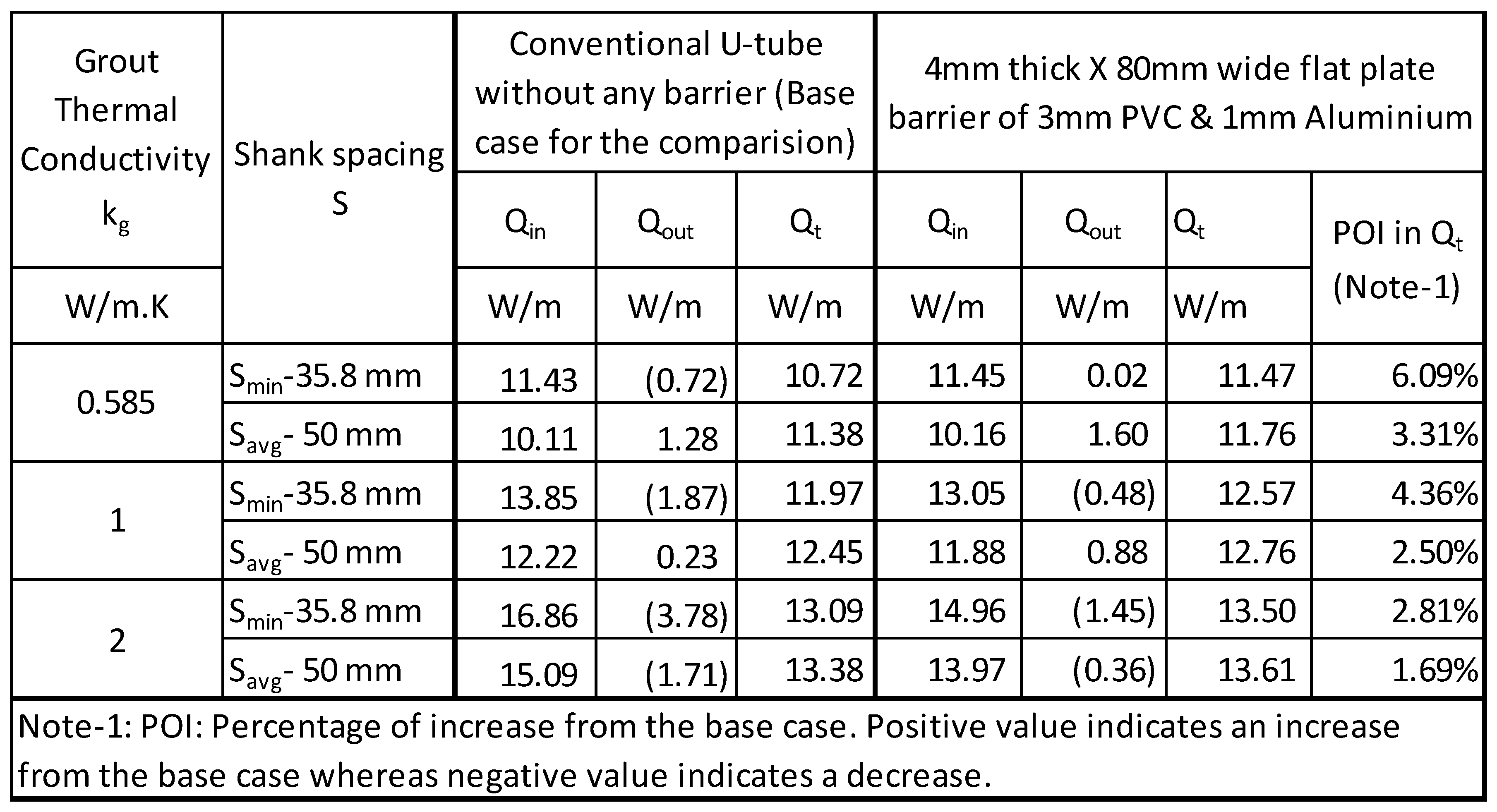
A noticeable increase in heat transfer especially at low thermal conductivity of grout and closer shank spacing results due to barrier.
3.4.2. 6mm Double Barrier:
Table 10 shows the results for the 6mm barrier for two different 3mm thick metallic barriers are used with 3mm PVC to form a 6mm thick barrier. The improvement in heat transfer for 6mm double barrier of PVC & stainless steel is less than observed for 4mm double barrier with PVC & aluminum.
3.3.4. Impact of Double Flat Plate Barrier on BHX Length:
Table 11 presents the indicative length of the Borehole Heat Exchanger (BHX) per kW of heat extracted from the soil, based on the analysis for 4mm double barrier (PVC& aluminum). The table includes results for three different soil thermal conductivities: 0.5, 1, and 2 W/m·K. Length of BHX for 6mm double flat plate barrier of PVC & stainless steel and PVC & brass is shown in Table 12.
The percentage reduction is the highest for the cases with low thermal conductivity grout of 0.585 W/m.K and closest shank spacing. The results of reduction in the BHX length by introducing double flat plate barrier are shown in Figure 18, Figure 19 and Figure 20 for soil thermal conductivity of 0.5, 1 & 2 W/m.K respectively.
3.3.4. Temperature Distribution in BHX with Double Flat Plate Barrier:
Figure 21, Figure 22 and Figure 23 show the temperature distribution within the BHX for a conventional -tube, a U-tube with 3mm PVC flat plate barrier and a U-tube with 3mm PVC & 0.2mm metal tape flat plate barrier. The temperature distribution shown is for minimum shank spacing at three different soils with thermal conductivity of 0.5, 1 and 2 W/m.K respectively. The thermal distribution of this double barrier arrangement is similar to, but improved compared to, the thermal distribution of the plastic flat plate barrier with a 0.2 mm metallic tape, as discussed in the previous section.
3.5. U-Tube with Single U-Barrier Arrangement:
3.5.1. U-Shape Plastic Barrier:
Table 13 depicts the results of single U-shape barrier of PVC plastic with 0.17 W/m.K. Soil thermal conductivity was 1 W/m.K in the analysis. The results showed that the BHX thermal resistance increased causing a reduction instead of an increase in the total heat transfer through the borehole after introducing 3mm thick plastic U-barrier. The trend is similar to the flat plate barrier case and the change of the barrier geometry from flat plate to U-shape does not help in heat transfer improvement in this case.
3.5.2. U-Shape Plastic Barrier with Self-Adhesive Metallic Tape:
Table 14 shows the resulting heat transfer and also shows the previously discussed plastic barrier of 0.17 W/m.K for a comparision of the changes after adding a metallic layer over the plastic barrier. At lower thermal conductivity grout of 0.585 W/m.K and at closest shank spacing of 35mm, the percentage increase in the overall heat transfer from the base case is the highest. The percentage increase in the heat transfer rate starts to dimish at increased shank spacings and thermal conductivity of the grout. Unlike to the flat plate barrier case, at lower thermal conductivity grout of 0.585 W/m.K, the heat transfer from the outlet pipe decreases from the base case. For other grouts of higher thermal conductivity also, the heat transfer in the outlet pipe reduces from a plastic U-barrier with no metal tape. Due to increase in the heat transfer of the inlet leg, in overll this arrangement improves the net heat transfer.
Figure 24, Figure 25 and Figure 26 show the temperature distribution within the BHX for a conventional -tube, a U-tube with 3mm PVC U- barrier and a U-tube with 3mm PVC & 0.2mm metal tape U-barrier for minimum shank spacing at three different soils thermal conductivity of 0.5, 1 and 2 W/m.K respectively.
The temperature in the BHX at few locations in different scenarios for minimum shank spacing and grout thermal conductivity of 0.585 W/m.K for Figure 24 are shown in Table 15. At the tip of the barrier, Location B, the temperature increases from 8.8 C (case a) to 9.2 C (case b) and tends to decrease again to 8.7 C for case c. Similarly, the BHX wall temperature. Location C, the temperature noticeably increases from 8.25 C (case a) to 9.0 C (case b) and tends to decrease again to 8.8 C for case c. Overall addition of metal tape is contributing to lowering the temperature of BHX area near the inlet pipe
3.5.3. U-Shape Metallic Barrier:
Table 15 shows the results of this analysis. Both 3 mm stainless steel barrier and 3mm brass barrier exhibited lower improvement in the net heat transfer than a plastic U-barrier with 0.2mm self-adhesive metallic tape, except one scenario. For farther shank spacings and at lower thermal conductivity grout of 0.585 W/m.K, the performance of 3mm brass barrier was found to be marginally better.
3.3.4. Impact of U-Barrier on BHX Length:
Table 16 presents the length of the Borehole Heat Exchanger (BHX) per kW of heat extracted from the soil, based on the analysis of U-barrier. The table includes results for three different soil thermal conductivities: 0.5, 1, and 2 W/m·K.
3.6. U-Tube with Double Flat Plate Barrier Arrangement:
3.6.1. 4mm Double U-Barrier:
Table 17 shows the results for the 4mm double U-barrier (3mm plastic & 1mm aluminum).
3.6.2. 6mm Double Barrier:
Table 18 shows the results for the 6mm double U-barrier for two different 3mm thick metallic barriers combined with 3mm PVC to form a 6mm thick barrier. The improvement in heat transfer for 6mm double flat plate barrier of PVC & stainless steel is lesser than observed for 4mm double barrier with PVC & aluminum.
3.6.3. Impact of Double U- Barrier on BHX Length:
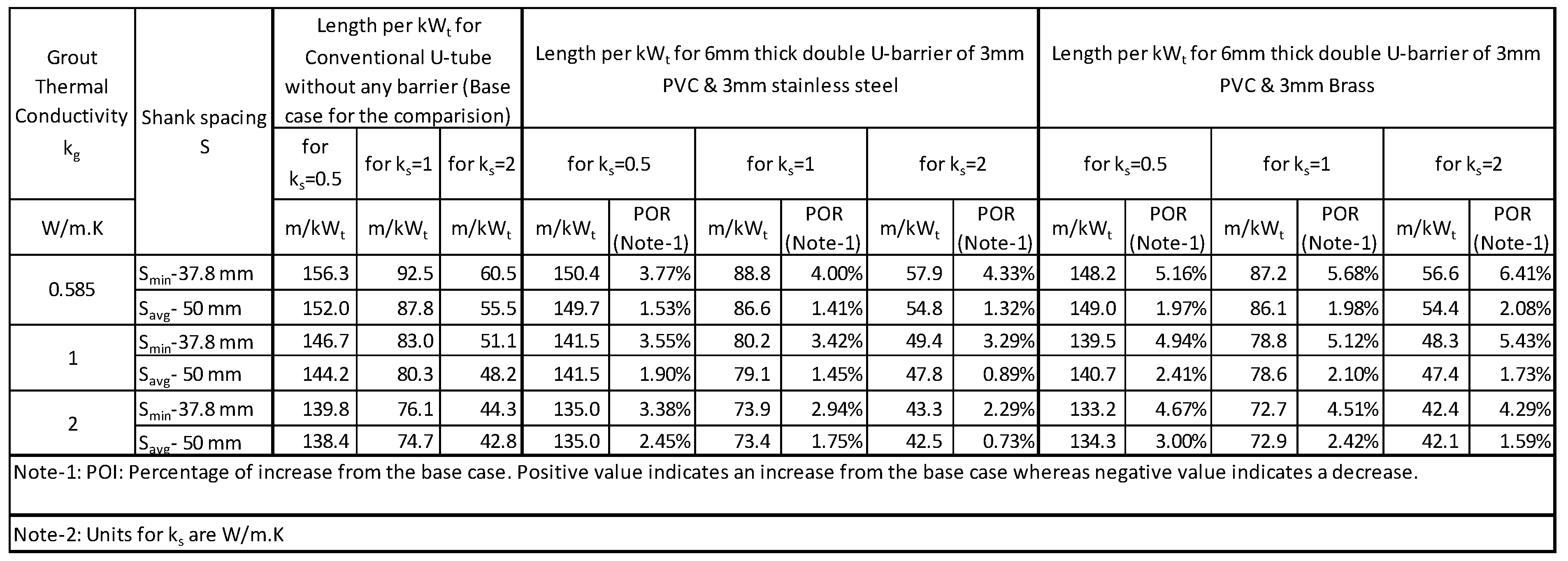
Table 19 presents the length of the Borehole Heat Exchanger (BHX) per kW of heat extracted from the soil, based on the analysis for 4mm double U-barrier (PVC& aluminum). The table includes results for three different soil thermal conductivities: 0.5, 1, and 2 W/m·K. Length of BHX for 6mm double U- barrier of PVC & stainless steel and PVC & brass is shown in Table 20.
3.6.4. Temperature Distribution in BHX with Double Flat Plate Barrier:
Figure 33, Figure 34 and Figure 35 show the temperature distribution within the BHX for a conventional -tube, a U-tube with 3mm PVC flat plate barrier and a U-tube with 3mm PVC & 0.2mm metal tape flat plate barrier. The temperature distribution shown is for minimum shank spacing at three different soils with thermal conductivity of 0.5, 1 and 2 W/m.K respectively. The thermal distribution of this double U-barrier arrangement is like, but improved compared to, the thermal distribution of the plastic U-barrier with a 0.2 mm metallic tape, as discussed in the previous section.
3. Discussion
The results of flat barrier are better than U shape barrier for most of the cases. The increase in heat transfer for double flat plate barrier, from the single metallic barrier, is not significant. For example, for grout thermal conductivity of 0.585 W/m.K, the net heat transfer further increases by 0.2 W/m only when a 3mm plastic barrier is added on the 3mm brass barrier. In the case of U-barrier, the difference between single and double barrier is comparatively more. For example, for grout thermal conductivity of 0.585 W/m.K, the net heat transfer further increases by 0.44 W/m when a 3mm plastic U-barrier is added on the 3mm brass U-barrier. The results of increase in the heat transfer for average shank spacing show a marginal increase only for almost all cases of single and double U barrier with a resulting reduction of less than 3% in the length of BHX.
The construction of a 3mm plastic barrier with 0.2mm metallic self-adhesive tape may be comparatively easier and lower in cost than the case of 4mm or 6mm double barrier; making this option a better choice over 4mm or 6mm double barrier.
The absolute decrease in the length of the BHX because of barrier is more for the lower thermal conductivity soil, however the percentage reduction is more for the higher thermal conductivity soil. For example, in the case of 3mm brass barrier, the absolute reduction of 6.4 m/kWt is the maximum absolute reduction in length for this case, however this length reduction is only 4.04% of the length without barrier under same conditions. The maximum reduction in terms of the percentage reduction in the length is 9.85% which is for soil thermal conductivity of 2 W/m.K. The absolute reduction in length for soil thermal conductivity of 2 W/m.K is 6.1 m/kWt. Because the absolute reduction in length is directly related to the cost of the BHX, comparison of absolute length reduction might lead to better decisions in terms of barrier selection.
Figure 36, Figure 37 and Figure 38 show the comparison of the BHX length per kW of heat transfer for different scenarios of flat plate barriers with U-tube and coaxial pipe arrangements, for soil thermal conductivity of 0.5, 1 and 2 W/m.K respectively. U-shape barrier was found to be less efficient to improve the heat transfer in the BHX than a flat plate barrier, therefore not considered in the comparison.
Due to the reduced heat transfer from the BHX in soils with lower thermal conductivity, short-circuit losses in the coaxial pipe arrangement significantly decrease the overall heat transfer efficiency. As a result, U-tube and U-tube barrier configurations are more effective in maximizing net heat transfer. To make coaxial pipes thermally efficient in lower thermal conductivity soil, improvement of the thermal insulation on the outlet pipe might be required.
The study can be continued for other coaxial pipe arrangements and double U-pipe arrangement. A cost-benefit analysis is also recommended for the selection of the type of BHX arrangement among the various options discussed for a given soil condition, specially where the difference between various options is marginal.
5. Conclusions
Flat plate and U-barrier configurations provide a viable alternative to conventional U-tube arrangements and may also serve as a better option than coaxial pipes in soils with low to moderate thermal conductivity. While flat plate barriers generally result in greater heat transfer improvement compared to U-barriers, the latter can still be a suitable choice if they offer additional advantages, such as easier installation and lower costs
Author Contributions
This research work was conducted as a part of Asfia Nishat’s Master by Research program supervised by Dr. Hossam Abuel Naga, at Latrobe University, Melbourne, Australia.
Nomenclature
| Db | Borehole diameter in mm or m |
| Dp | Pipe external diameter in mm or m |
| h | Convective heat transfer coefficient of the fluid in W/m2K |
| kg | Grout thermal conductivity in W/mK |
| kp | Pipe thermal conductivity in W/mK |
| ks | soil thermal conductivity in W/mK |
| kWt | kilo-watt thermal |
| L | Length of U tube pipe |
| Q or q | Heat flow rate in W/m |
| Qin | Heat transfer rate in the inlet pipe in W/m |
| Qout | Heat transfer rate in the outlet pipe in W/m |
| qgen | Heat generated in W |
| r1 | Pipe internal radius in mm or m |
| rb | Borehole radius in mm or m |
| Rb | Thermal resistance of borehole in (W/mK)-1
|
| Rg | Thermal resistance of grout in (W/mK)-1
|
| Rp | Thermal resistance of pipe in (W/mK)-1
|
| Rs | Thermal resistance of soil in (W/mK)-1
|
| Rt | Total thermal resistance of BHX in (W/mK)-1
|
| S or s | Shank spacing in mm or m |
| Smax | Maximum Shank spacing in mm or m |
| Savg | Average Shank spacing in mm or m |
| Smin | Minimum Shank spacing in mm or m |
| T0 | undisturbed ground temperature in °C |
| Tbhw | temperature of borehole wall in °C |
| Tf | Average Fluid Temperature of inlet and outlet pipe of U tube heat exchanger in °C |
| Tfi | Average Fluid Temperature of inlet pipe of U tube heat exchanger in °C |
| Tfo | Average Fluid Temperature of outlet pipe of U tube heat exchanger in °C |
| τ | Time |
| α | Thermal diffusivity in m2/s |
| γ | Euler's constant = 0.5772 |
Abbreviations
| ASHRAE | American Society of Heating, Refrigeration & Air-conditioning Engineers |
| BHX | Borehole heat exchanger |
| GSHP | Ground source heat pump |
| HX | Heat exchanger |
| PDE | Partial differential equation |
| TRT | Thermal response test |
| uPVC | Un-plasticized Polyvinyl Chloride |
References
- Sarbu, I.; Sebarchievici, C. Using Ground-Source Heat Pump Systems for Heating/Cooling of Buildings. In Advances in Geothermal Energy; 2016; p. 17.
- Kavanaugh, S.; Rafferty, K. Geothermal heating and-Cooling, Design of Ground Source heat Pump systems; W. Stephen Comstock: 2014.
- Committees, A.T. ASHRAE Handbook, Applications, SI Edition 2023; 2023.
- Yoon, S.; Lee, S.-R.; Go, G.-H. A numerical and experimental approach to the estimation of borehole thermal resistance in ground heat exchangers. Energy 2014, 71, 547–555. [Google Scholar] [CrossRef]
- Kerme, E.D.; Fung, A.S.; Leong, W.H. Analysis of the Combined Effect of Major Influencing Parameters for Designing High-Performance Single (sBHE) and Double (dBHE) U-Tube Borehole Heat Exchangers. Energies 2024, 17. [Google Scholar] [CrossRef]
- Junhao Shen, C.Z. , Yongqiang Luo, Zhiyong Tian, Shicong Zhang, Jianhua Fan, Zhang Ling. Comprehensive thermal performance analysis and optimization study on U-type deep borehole ground source heat pump systems based on a new analytical model. Energy 2023, 274. [Google Scholar]
- Fridleifsson, I.B., R. Bertani, E. Huenges, J. W. Lund, A. Ragnarsson, and L. Rybach. The possible role and contribution of geothermal energy to the mitigation of climate change. In Proceedings of the IPCC Geothermal, Luebeck, Germany, 20–25 January 2008.
- Xiaobing Liu, Y.P., Defeng Qian & Joshua Mcdonald. An Analysis on Cost Reduction Potential of Vertical Bore Ground Heat Exchangers Used for Ground Source Heat Pump Systems. In Proceedings of the Stanford Geothermal Workshop 44th Annual Conference, Stanford, California, United States of America, 2019.
- E. Zanchini, S.L.a.A.P., et al., Effects of flow direction and thermal short-circuiting on the performance of coaxial ground heat exchangers, in International Conference on Renewable Energies and Power Quality (ICREPQ’09) 2009: Valencia, Spain.
- Christopher, S.; Brown, I.K. David Banks, Gioia Falcone. omparison of the thermal and hydraulic performance of single U-tube, double U-tube and coaxial medium-to-deep borehole heat exchangers, Geothermics. Geothermics 2024, 117. [Google Scholar]
- Chen, J.; Qiao, W.; Xue, Q.; Zheng, H.; An, E. Research on ground-coupled heat exchangers. International Journal of Low-Carbon Technologies 2010, 5, 35–41. [Google Scholar] [CrossRef]
- Chen, H.; Tomac, I. Technical review on coaxial deep borehole heat exchanger. Geomechanics and Geophysics for Geo-Energy and Geo-Resources 2023, 9. [Google Scholar] [CrossRef]
- Al-Chalabi, R. Thermal Resistance of U-tube Borehole Heat Exchanger System: Numerical Study 2013.
- Ngo, I.L.; Ngo, V.H. A new design of ground heat exchanger with insulation plate for effectively geothermal management. Geothermics 2022, 105. [Google Scholar] [CrossRef]
- Eskilson, P. Thermal Analysis of Heat Extraction Boreholes. University of Lund, Sweden, 1987.
- Lamarche, L. Fundamentals ofGeothermal Heat Pump Systems Design and Application; Springer Nature Switzerland AG 2020.
- Ruan, W.a.H., William Travis. Model-Based Performance Analysis of a Single Borehole in Ground Heat Exchanger. In Proceedings of the International High Performance Buildings Conference, Purdue, 12–15 July 2010.
- Zhou, K.; Mao, J.; Li, Y.; Zhang, H.; Deng, Z. Prediction and parametric analysis of 3D borehole and total internal thermal resistance of single U-tube borehole heat exchanger for ground source heat pumps. Energy and Built Environment 2023, 4, 179–194. [Google Scholar] [CrossRef]
- ASHRAE Handbook, Fundamentals; ASHRAE: 2021.
- Louis Lamarche, S.K. , Benoit Beauchamp. A review of methods to evaluate borehole thermal resistances in geothermal heat-pump systems. Geothermics 2010, 39, 187–200. [Google Scholar] [CrossRef]
- Advances in Ground-Source Heat Pump Systems; Elsevier Science & Technology: 2016.
- Luo, Y.; Xu, G.; Yan, T. Performance evaluation and optimization design of deep ground source heat pump with non-uniform internal insulation based on analytical solutions. Energy and Buildings 2020, 229. [Google Scholar] [CrossRef]
Figure 1.
Schematic diagram showing (a) a typical vertical borehole heat exchanger (b) Section AA of borehole (c) Thermal resistance network of borehole.
Figure 1.
Schematic diagram showing (a) a typical vertical borehole heat exchanger (b) Section AA of borehole (c) Thermal resistance network of borehole.
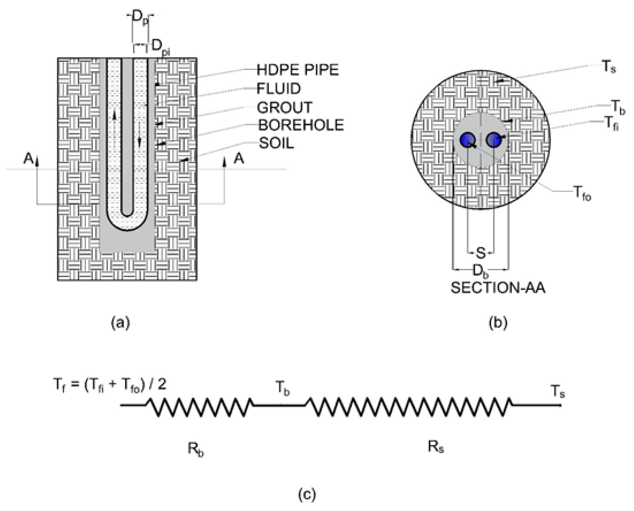
Figure 2.
Schematic diagram showing coaxial pipe arrangement for VBHX (a) Arrangement with inlet flow in the outer pipe (b) Arrangement with inlet flow in the inner pipe (c) Section AA of borehole.
Figure 2.
Schematic diagram showing coaxial pipe arrangement for VBHX (a) Arrangement with inlet flow in the outer pipe (b) Arrangement with inlet flow in the inner pipe (c) Section AA of borehole.
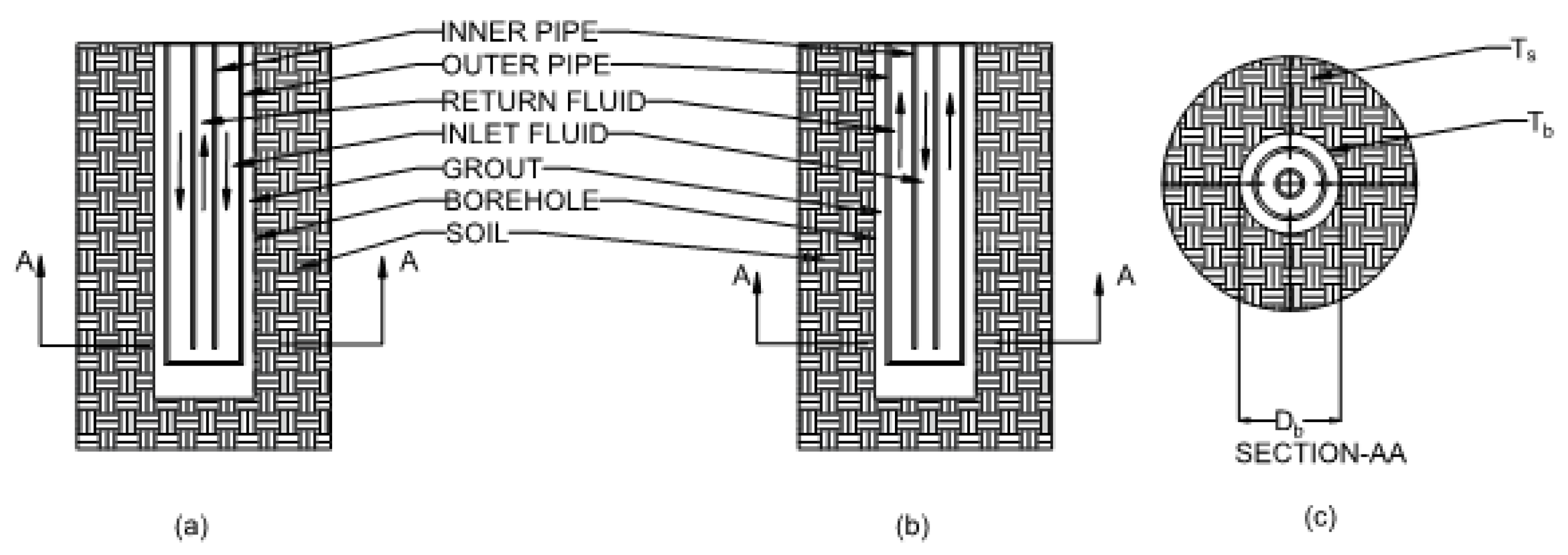
Figure 3.
U-tube model.
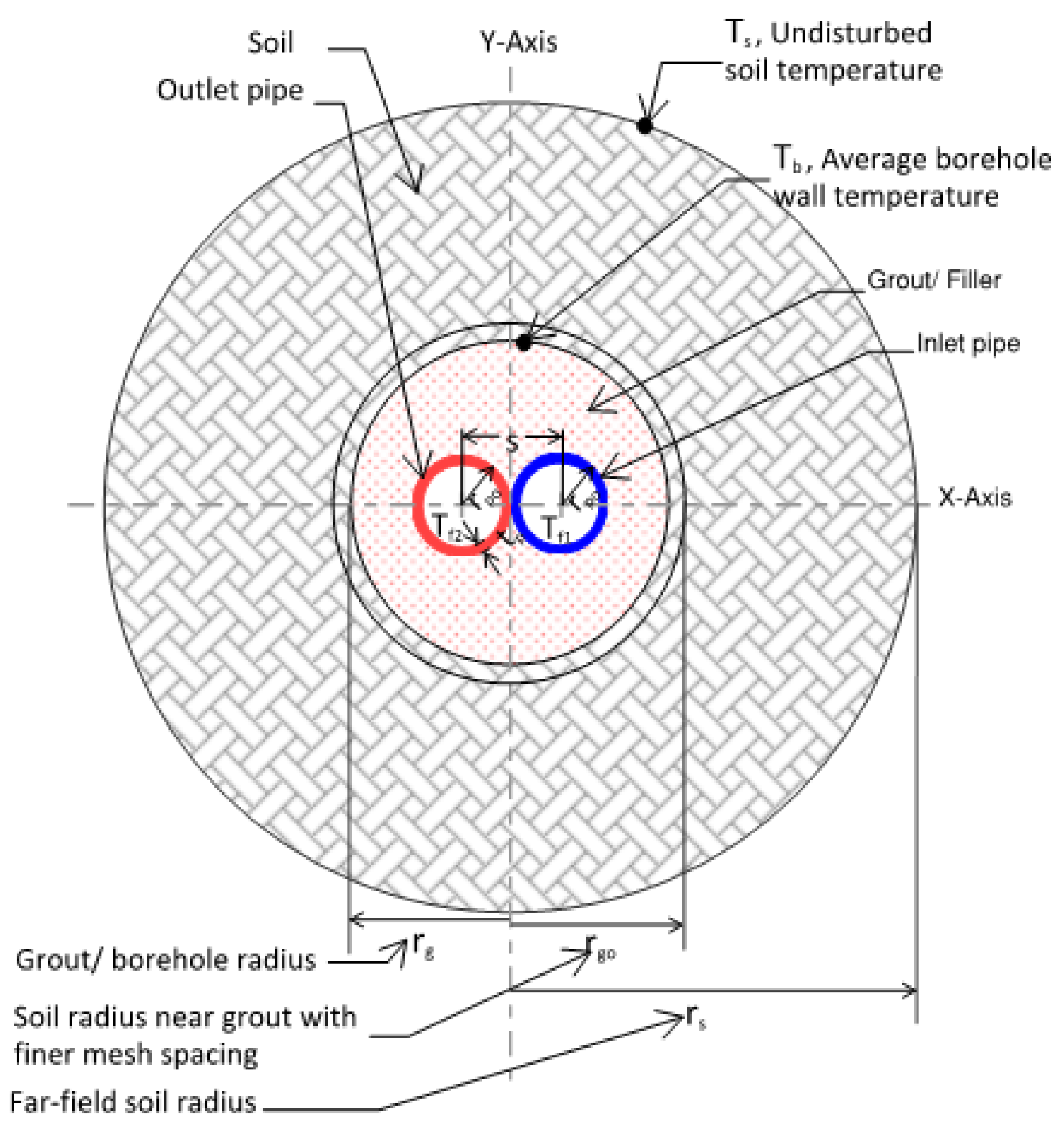
Figure 4.
Heat transfer from U-tube for soil thermal conductivity of (a) 0.5 W/m.K (b) 1 W/m.K (c) 2 W/m.K.
Figure 4.
Heat transfer from U-tube for soil thermal conductivity of (a) 0.5 W/m.K (b) 1 W/m.K (c) 2 W/m.K.
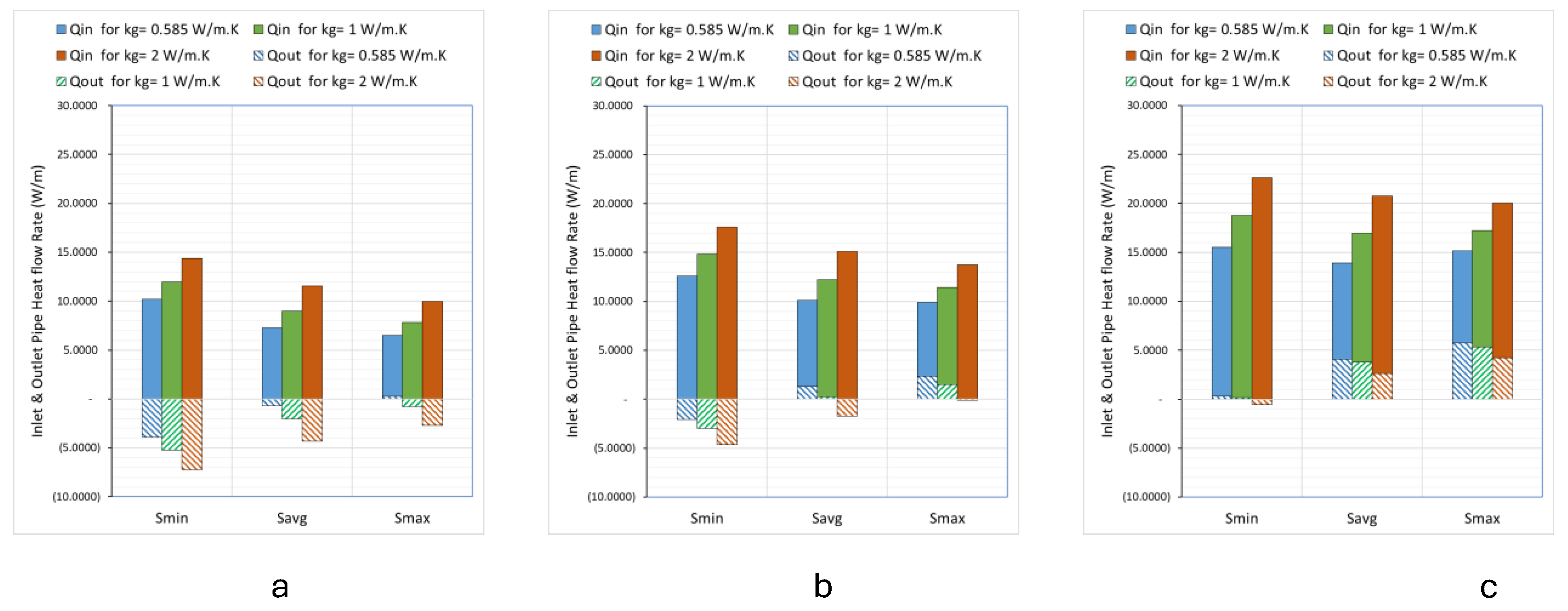
Figure 5.
Coaxial pipes model.
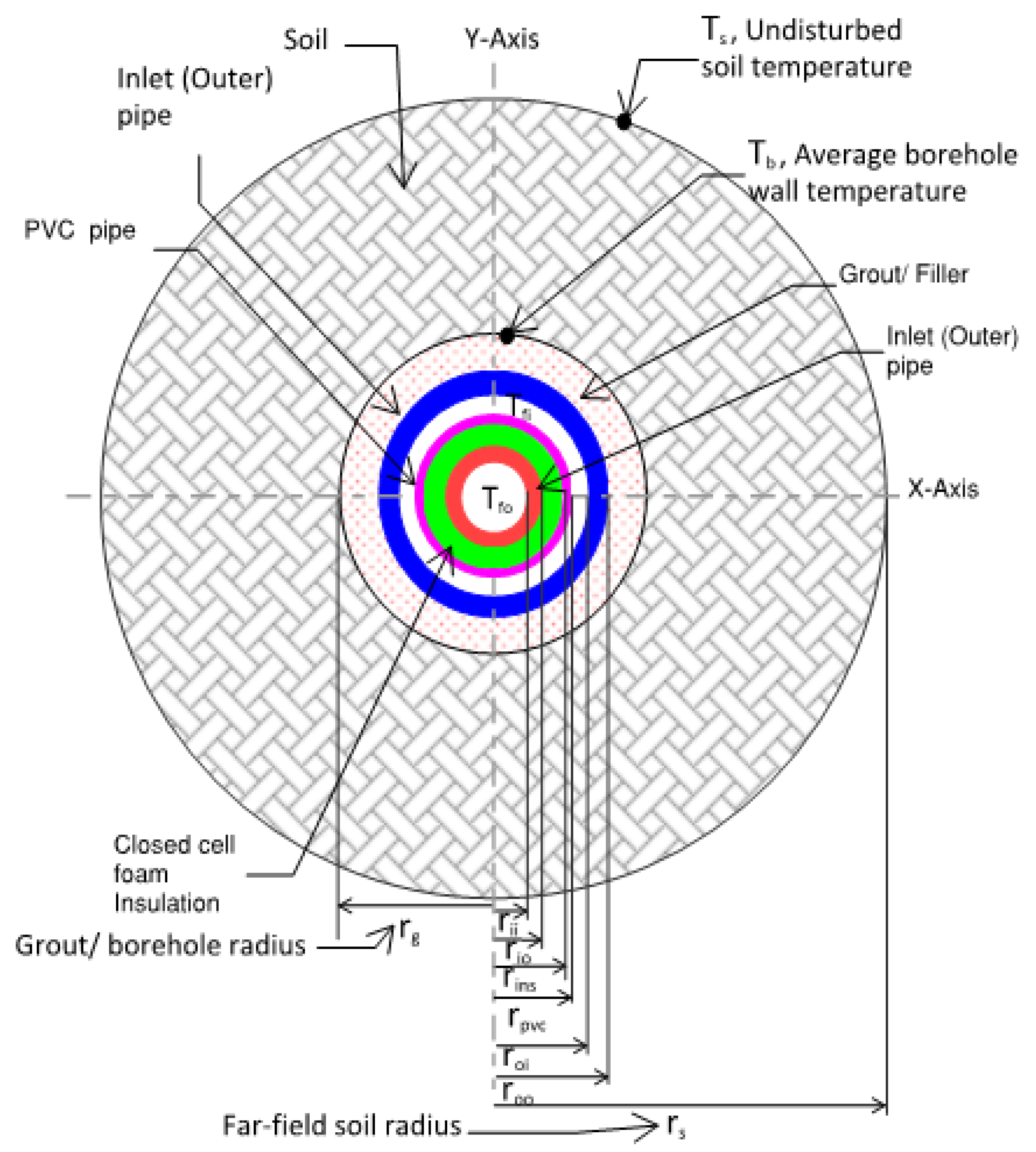
Figure 6.
Heat flow from the inlet & outlet pipes for insulated coaxial pipe arrangement with flow entering through the annular (outer) pipe.
Figure 6.
Heat flow from the inlet & outlet pipes for insulated coaxial pipe arrangement with flow entering through the annular (outer) pipe.
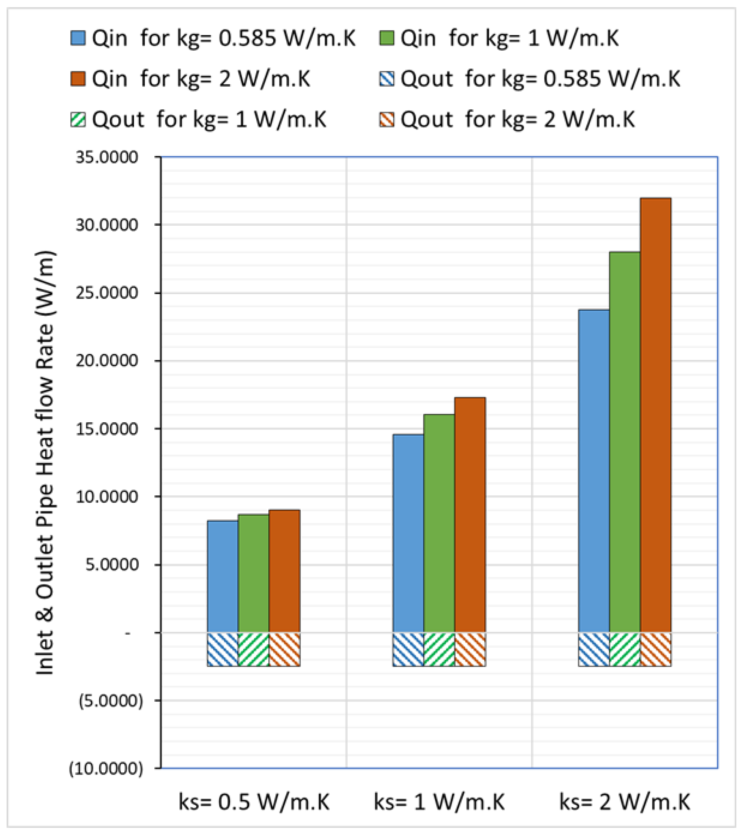
Figure 8.
Flat plate single & double barriers.
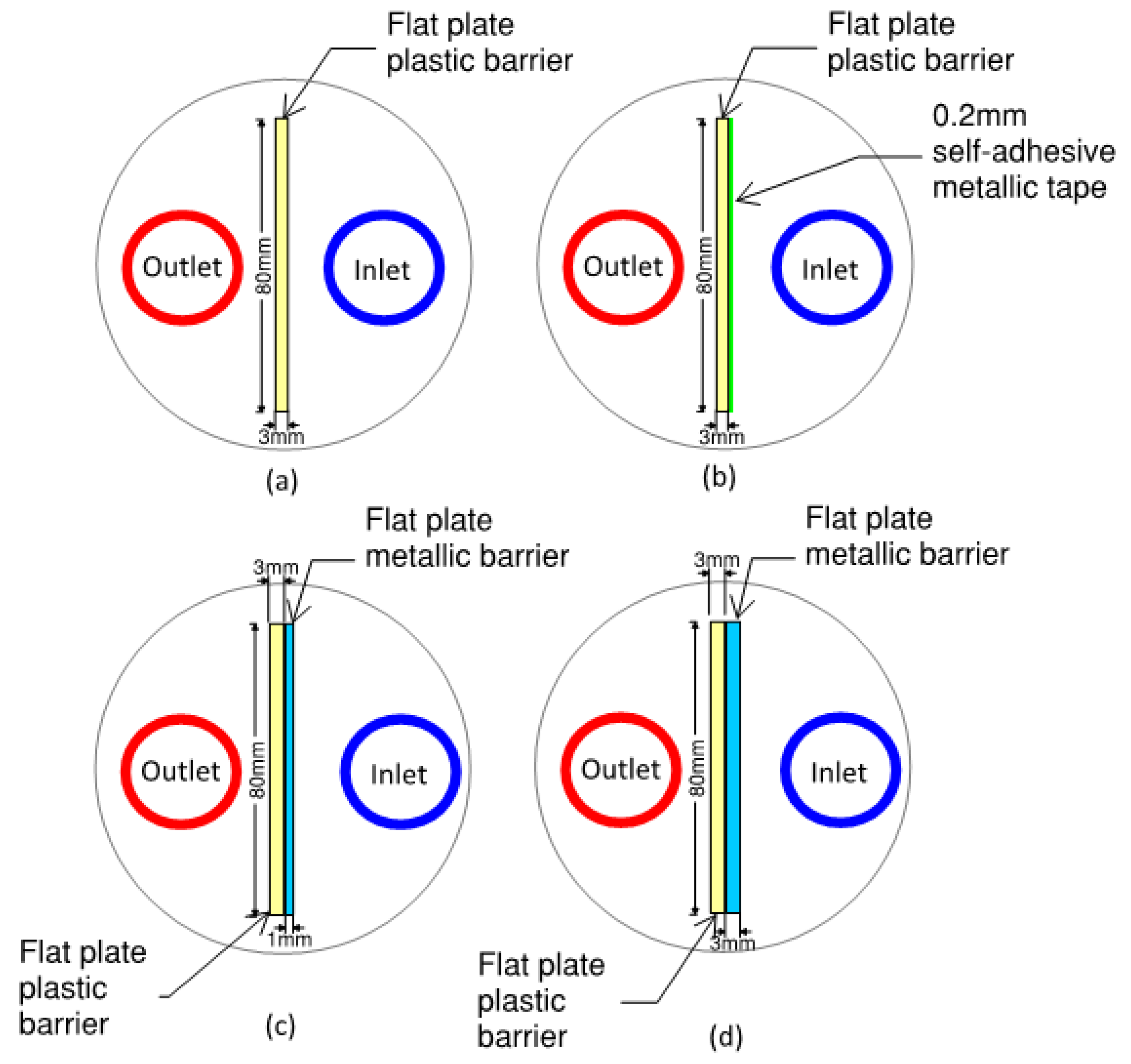
Figure 9.
U-shape single and double barriers.
Figure 10.
Net heat transfer for uninsulated U-tube and U-tube with insulated outlet leg.
Figure 11.
Net heat transfer for U-tube and coaxial pipe arrangement.
Figure 12.
Temperature distribution for different grouts at minimum shank spacing and soil thermal conductivity is 0.5 W/m.K for (a) Conventional U-tube (b) 3mm PVC plastic flat plate barrier & (c) 3mm PVC plastic flat plate barrier with 0.2mm self-adhesive metal tape.
Figure 12.
Temperature distribution for different grouts at minimum shank spacing and soil thermal conductivity is 0.5 W/m.K for (a) Conventional U-tube (b) 3mm PVC plastic flat plate barrier & (c) 3mm PVC plastic flat plate barrier with 0.2mm self-adhesive metal tape.
Figure 13.
Temperature distribution for different grouts at minimum shank spacing and soil thermal conductivity is 1 W/m.K for (a) Conventional U-tube (b) 3mm PVC plastic flat plate barrier & (c) 3mm PVC plastic flat plate barrier with 0.2mm self-adhesive metal tape.
Figure 13.
Temperature distribution for different grouts at minimum shank spacing and soil thermal conductivity is 1 W/m.K for (a) Conventional U-tube (b) 3mm PVC plastic flat plate barrier & (c) 3mm PVC plastic flat plate barrier with 0.2mm self-adhesive metal tape.
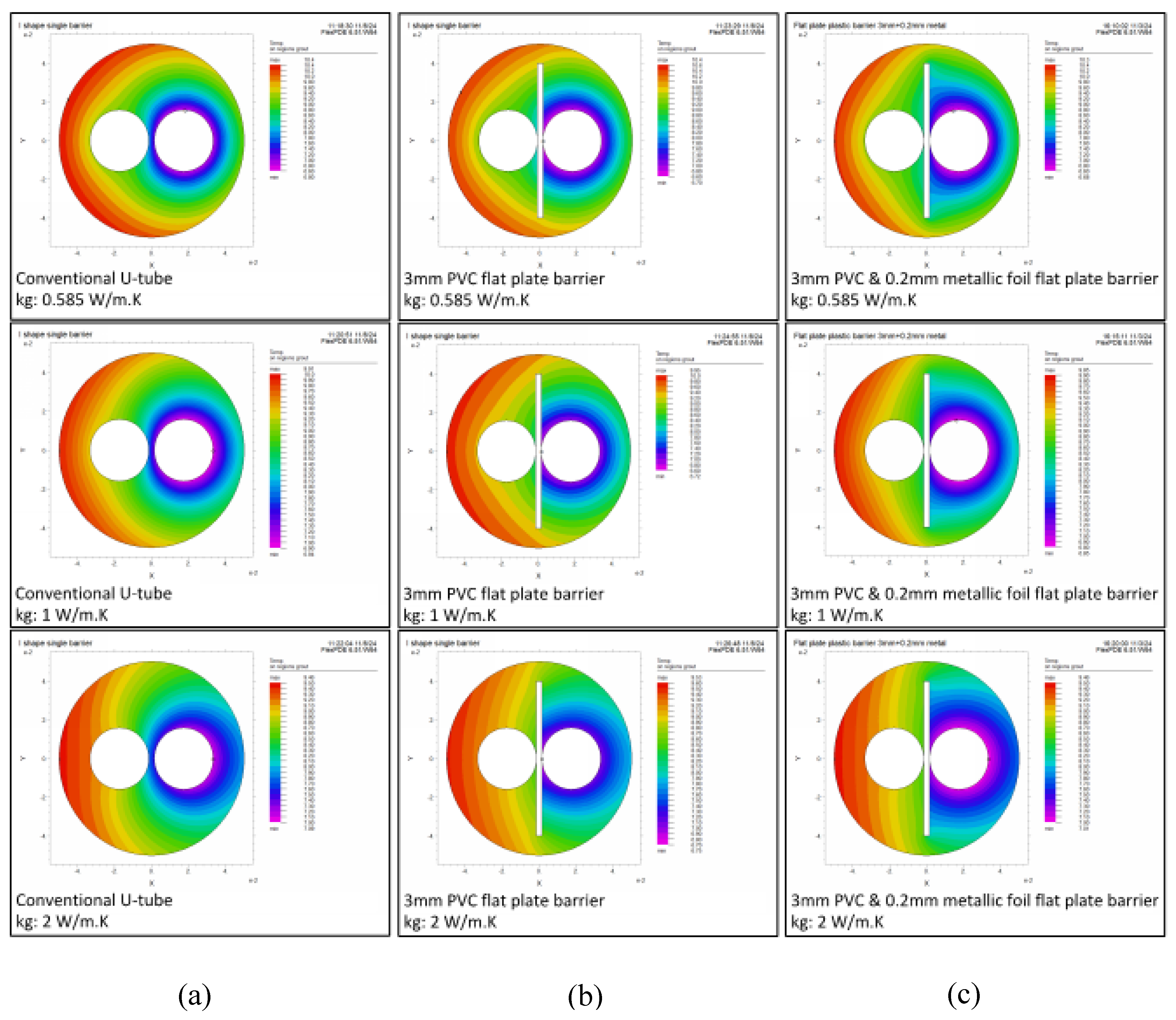
Figure 14.
Temperature distribution for different grouts at minimum shank spacing and soil thermal conductivity is 1 W/m.K for (a) Conventional U-tube (b) 3mm PVC plastic flat plate barrier & (c) 3mm PVC plastic flat plate barrier with 0.2mm self-adhesive metal tape.
Figure 14.
Temperature distribution for different grouts at minimum shank spacing and soil thermal conductivity is 1 W/m.K for (a) Conventional U-tube (b) 3mm PVC plastic flat plate barrier & (c) 3mm PVC plastic flat plate barrier with 0.2mm self-adhesive metal tape.
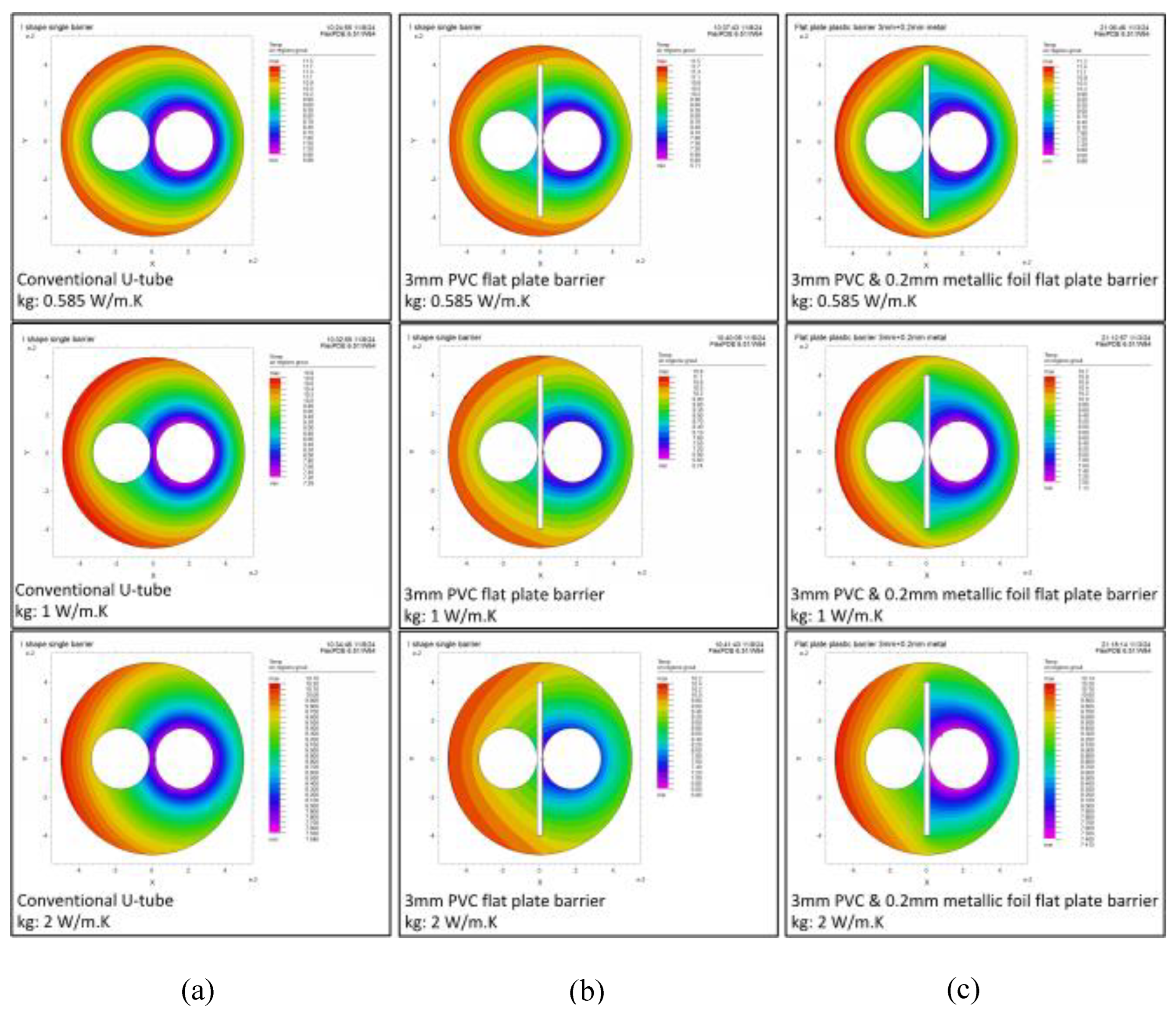
Figure 15.
Reduction in the BHX length for various flat plate barriers- Soil thermal conductivity: 0.5 W/m.K.
Figure 15.
Reduction in the BHX length for various flat plate barriers- Soil thermal conductivity: 0.5 W/m.K.
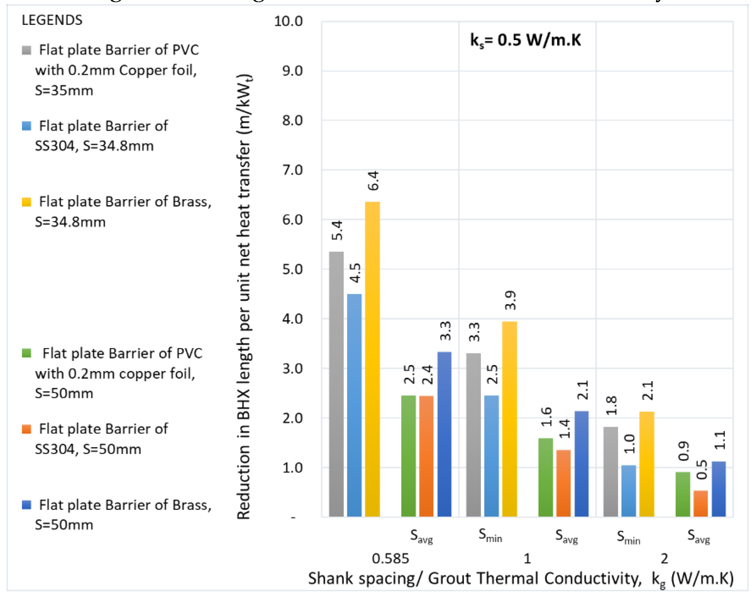
Figure 16.
Reduction in the BHX length for various flat plate barriers- Soil thermal conductivity: 1 W/m.K.
Figure 16.
Reduction in the BHX length for various flat plate barriers- Soil thermal conductivity: 1 W/m.K.
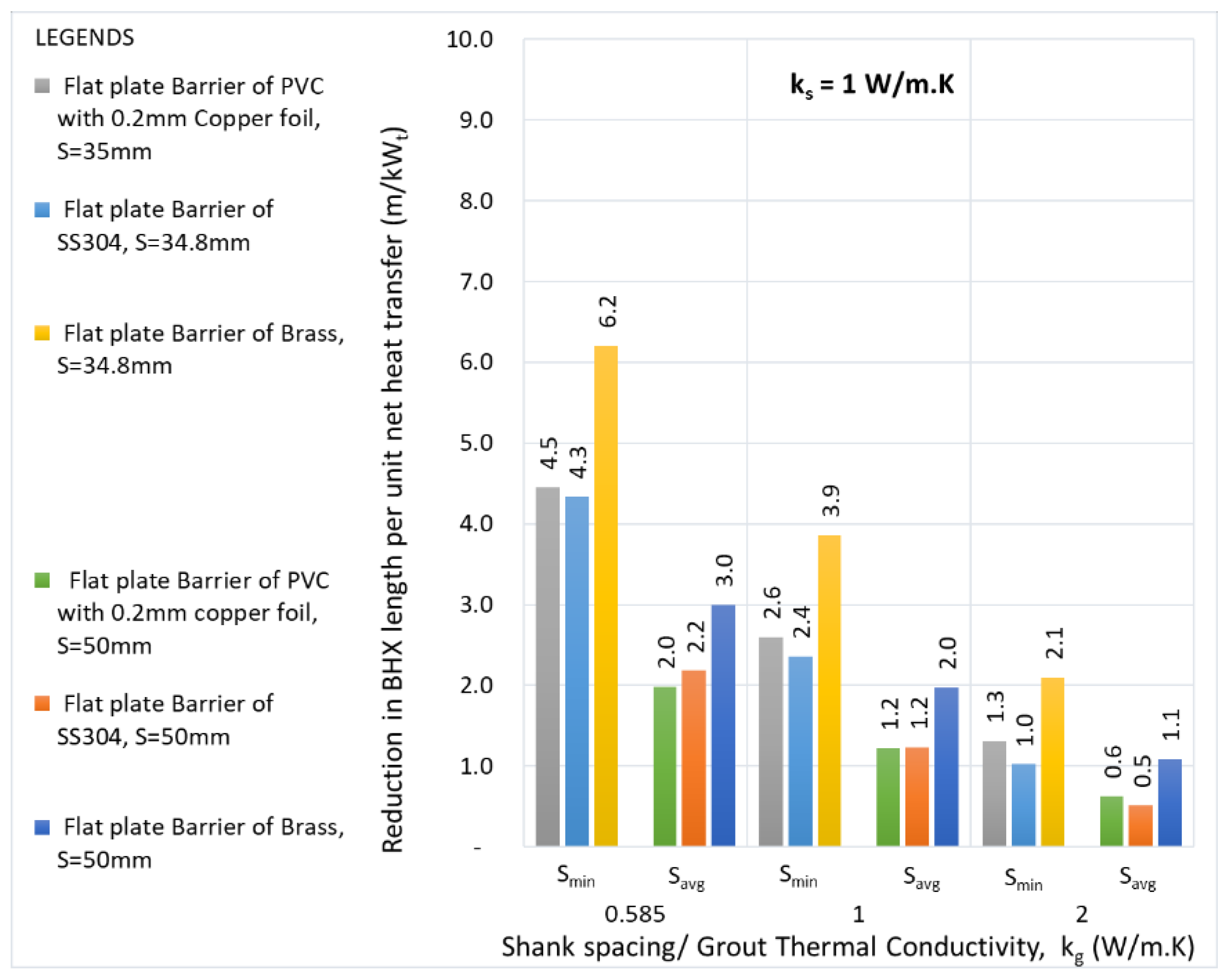
Figure 17.
Reduction in the BHX length for various flat plate barriers- Soil thermal conductivity: 2 W/m.K.
Figure 17.
Reduction in the BHX length for various flat plate barriers- Soil thermal conductivity: 2 W/m.K.
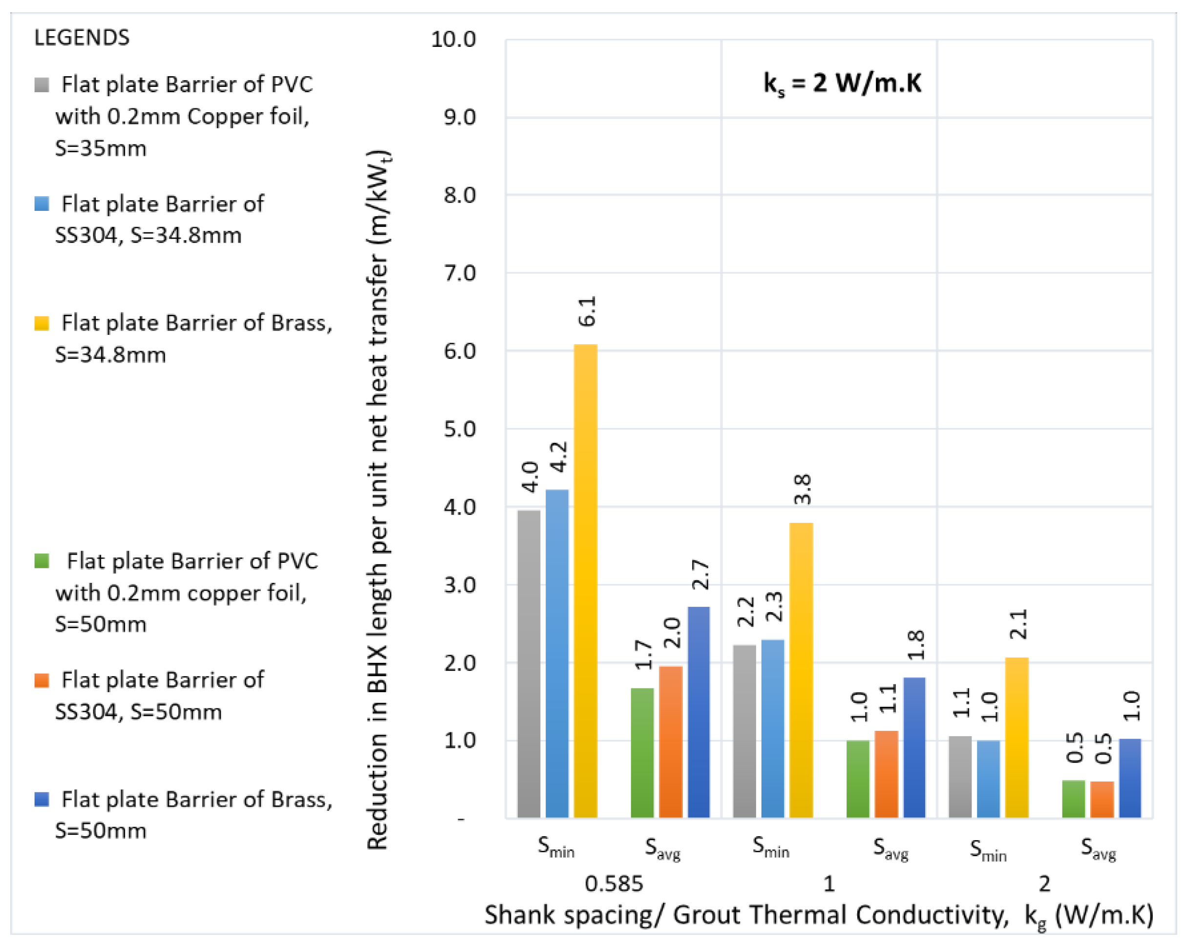
Figure 18.
Reduction in the BHX length for various flat plate double barriers- Soil thermal conductivity: 0.5 W/m.K.
Figure 18.
Reduction in the BHX length for various flat plate double barriers- Soil thermal conductivity: 0.5 W/m.K.
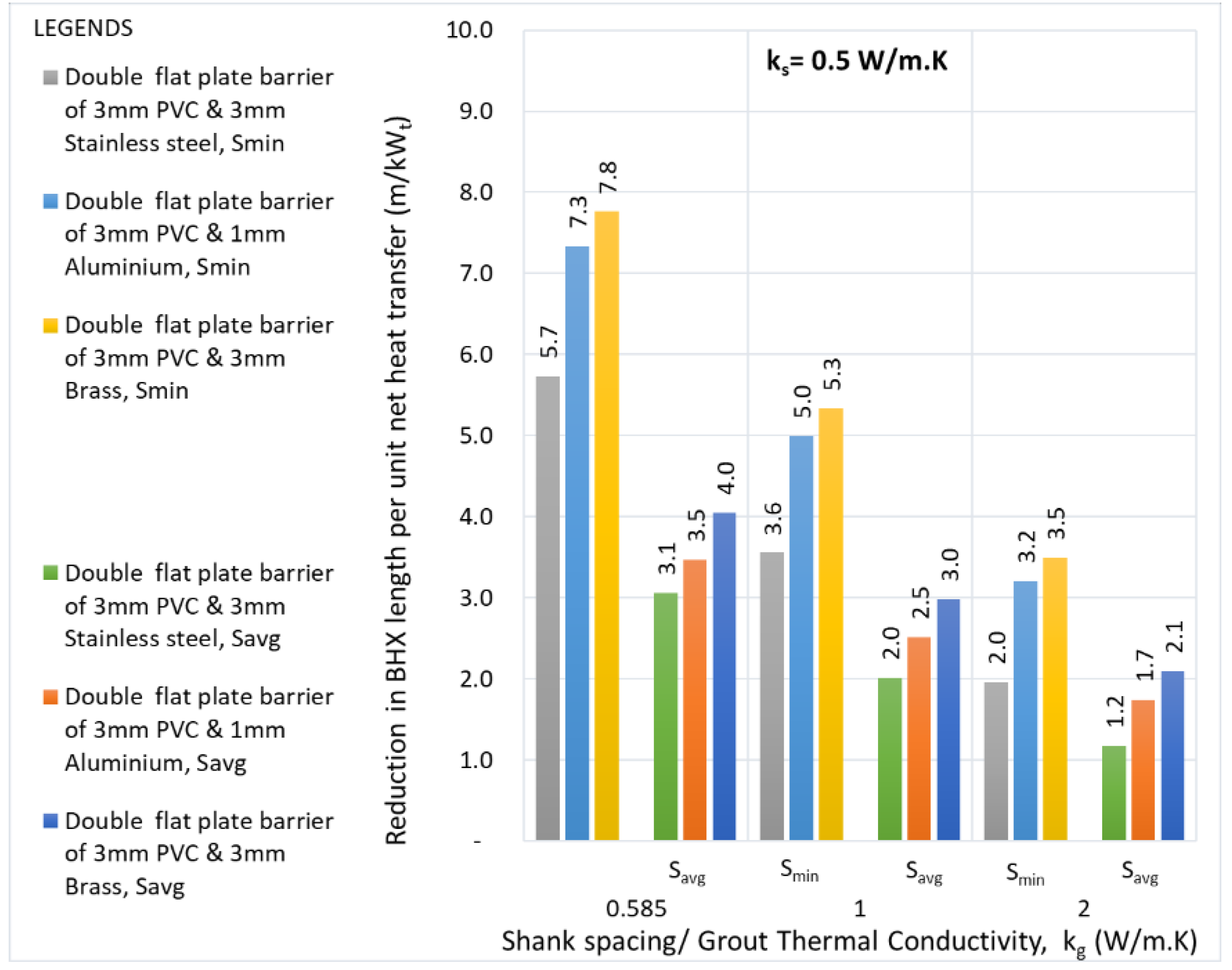
Figure 19.
Reduction in the BHX length for various flat plate double barriers- Soil thermal conductivity: 1 W/m.K.
Figure 19.
Reduction in the BHX length for various flat plate double barriers- Soil thermal conductivity: 1 W/m.K.
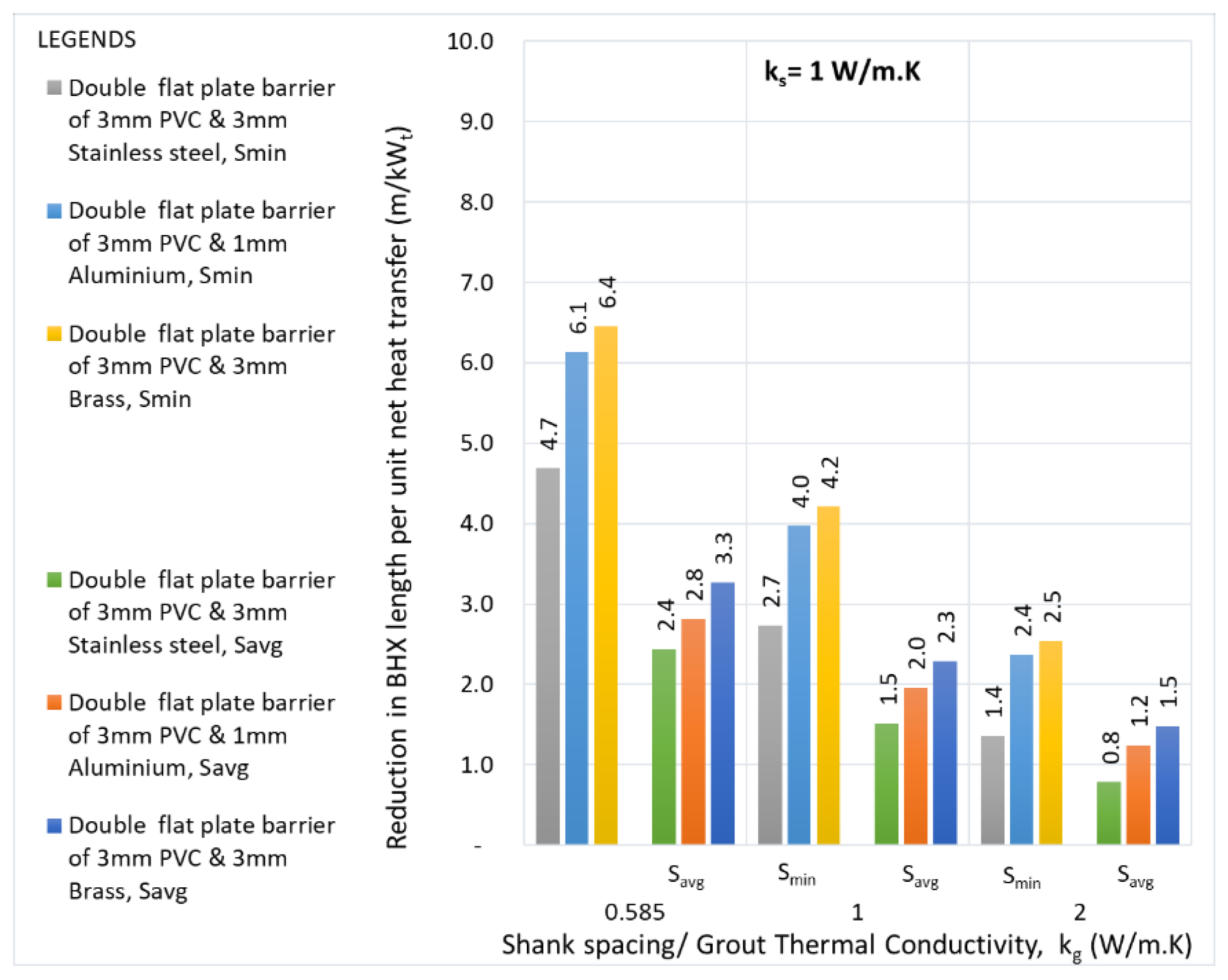
Figure 20.
Reduction in the BHX length for various flat plate double barriers- Soil thermal conductivity: 2 W/m.K.
Figure 20.
Reduction in the BHX length for various flat plate double barriers- Soil thermal conductivity: 2 W/m.K.
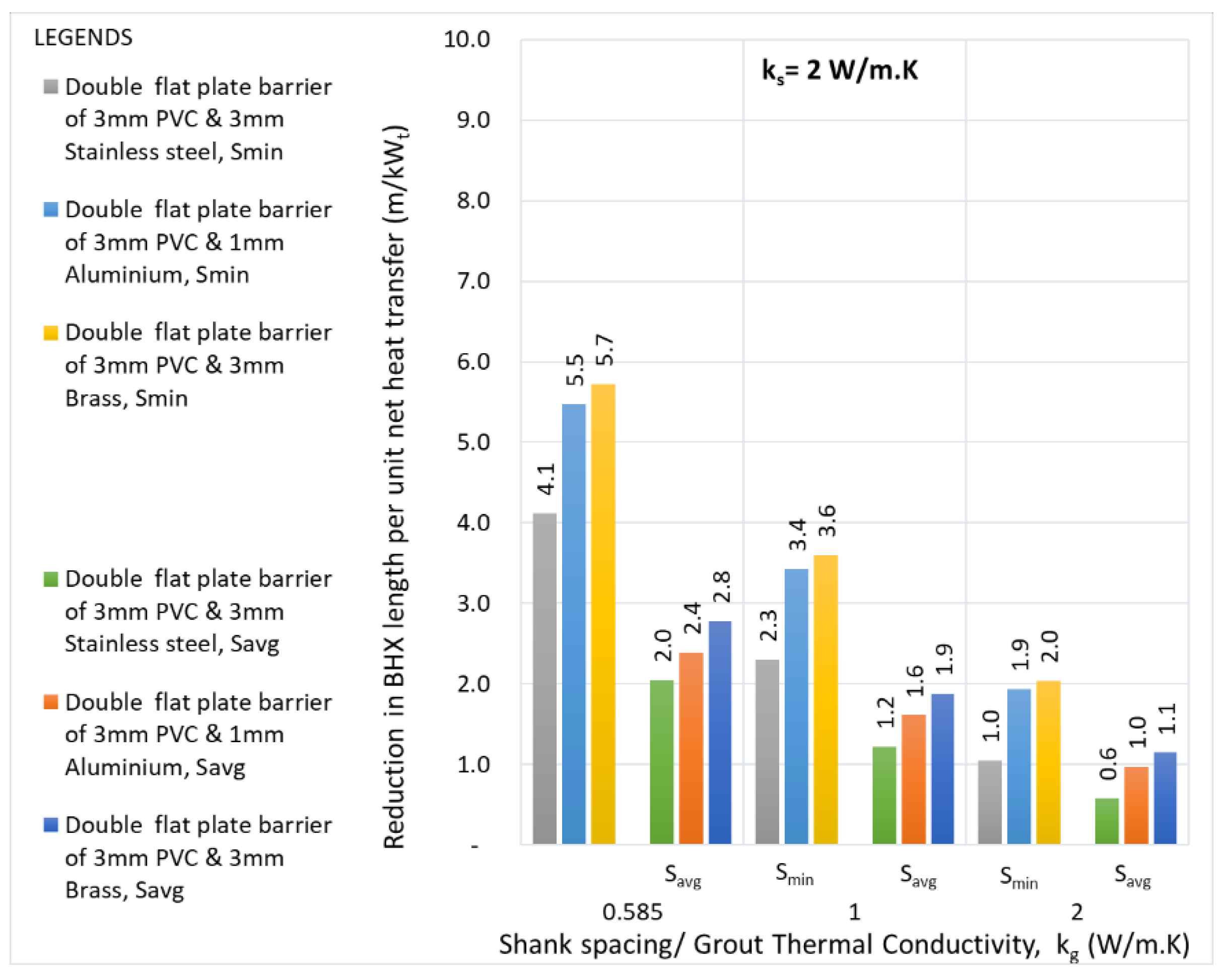
Figure 21.
Temperature distribution for different grouts at minimum shank spacing and soil thermal conductivity of 0.5 W/m.K for (a) Conventional U-tube (b) 3mm PVC & 3mm brass double flat plate barrier.
Figure 21.
Temperature distribution for different grouts at minimum shank spacing and soil thermal conductivity of 0.5 W/m.K for (a) Conventional U-tube (b) 3mm PVC & 3mm brass double flat plate barrier.

Figure 22.
Temperature distribution for different grouts at minimum shank spacing and soil thermal conductivity of 1 W/m.K for (a) Conventional U-tube (b) 3mm PVC & 3mm brass double flat plate barrier.
Figure 22.
Temperature distribution for different grouts at minimum shank spacing and soil thermal conductivity of 1 W/m.K for (a) Conventional U-tube (b) 3mm PVC & 3mm brass double flat plate barrier.
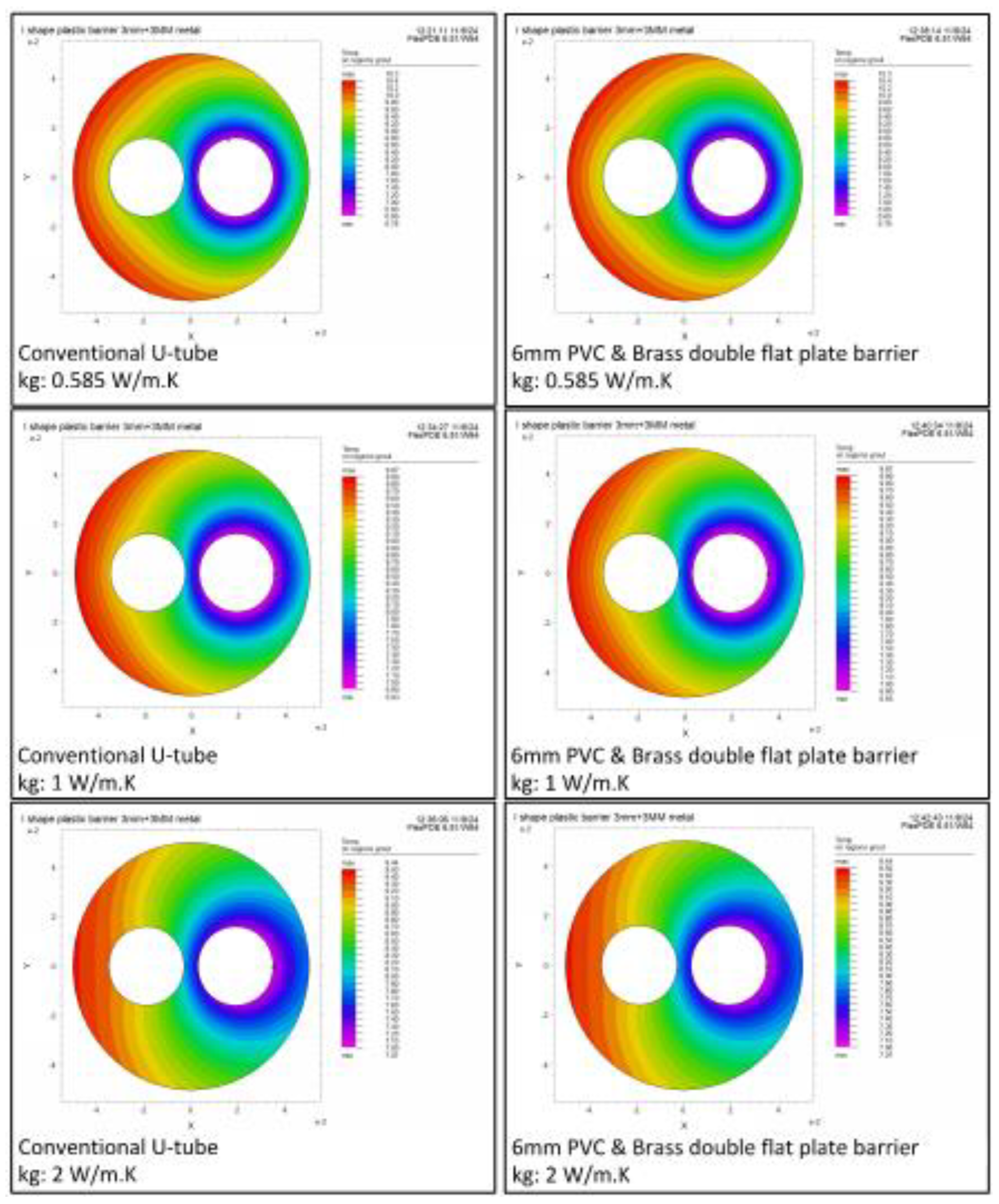
Figure 23.
Temperature distribution for different grouts at minimum shank spacing and soil thermal conductivity of 2 W/m.K for (a) Conventional U-tube (b) 3mm PVC & 3mm brass double flat plate barrier.
Figure 23.
Temperature distribution for different grouts at minimum shank spacing and soil thermal conductivity of 2 W/m.K for (a) Conventional U-tube (b) 3mm PVC & 3mm brass double flat plate barrier.
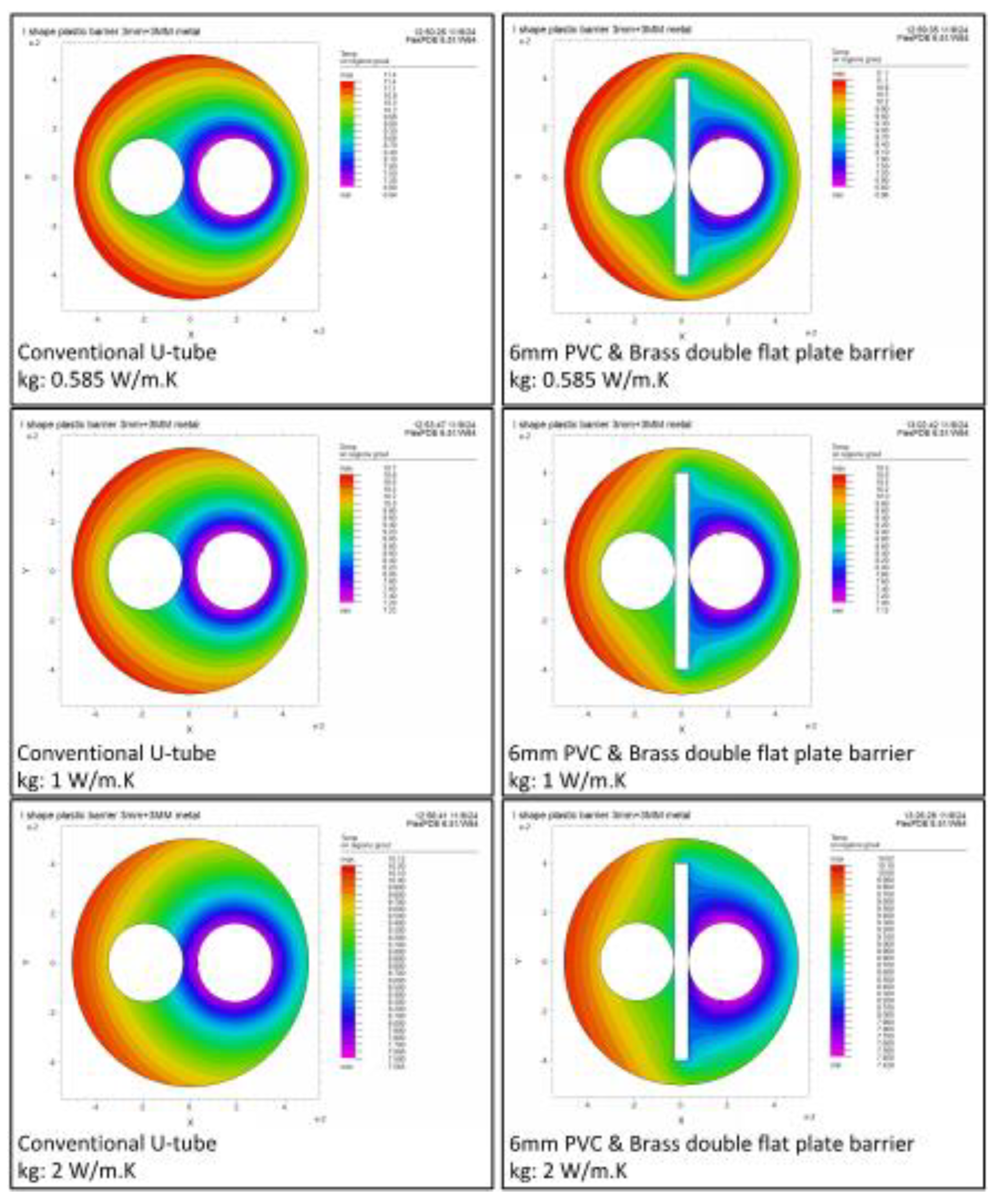
Figure 24.
Temperature distribution for different grouts at minimum shank spacing and soil thermal conductivity of 0.5 W/m.K for (a) Conventional U-tube (b) 3mm PVC plastic U-barrier & (c) 3mm PVC plastic U-barrier with 0.2mm self-adhesive metal tape.
Figure 24.
Temperature distribution for different grouts at minimum shank spacing and soil thermal conductivity of 0.5 W/m.K for (a) Conventional U-tube (b) 3mm PVC plastic U-barrier & (c) 3mm PVC plastic U-barrier with 0.2mm self-adhesive metal tape.
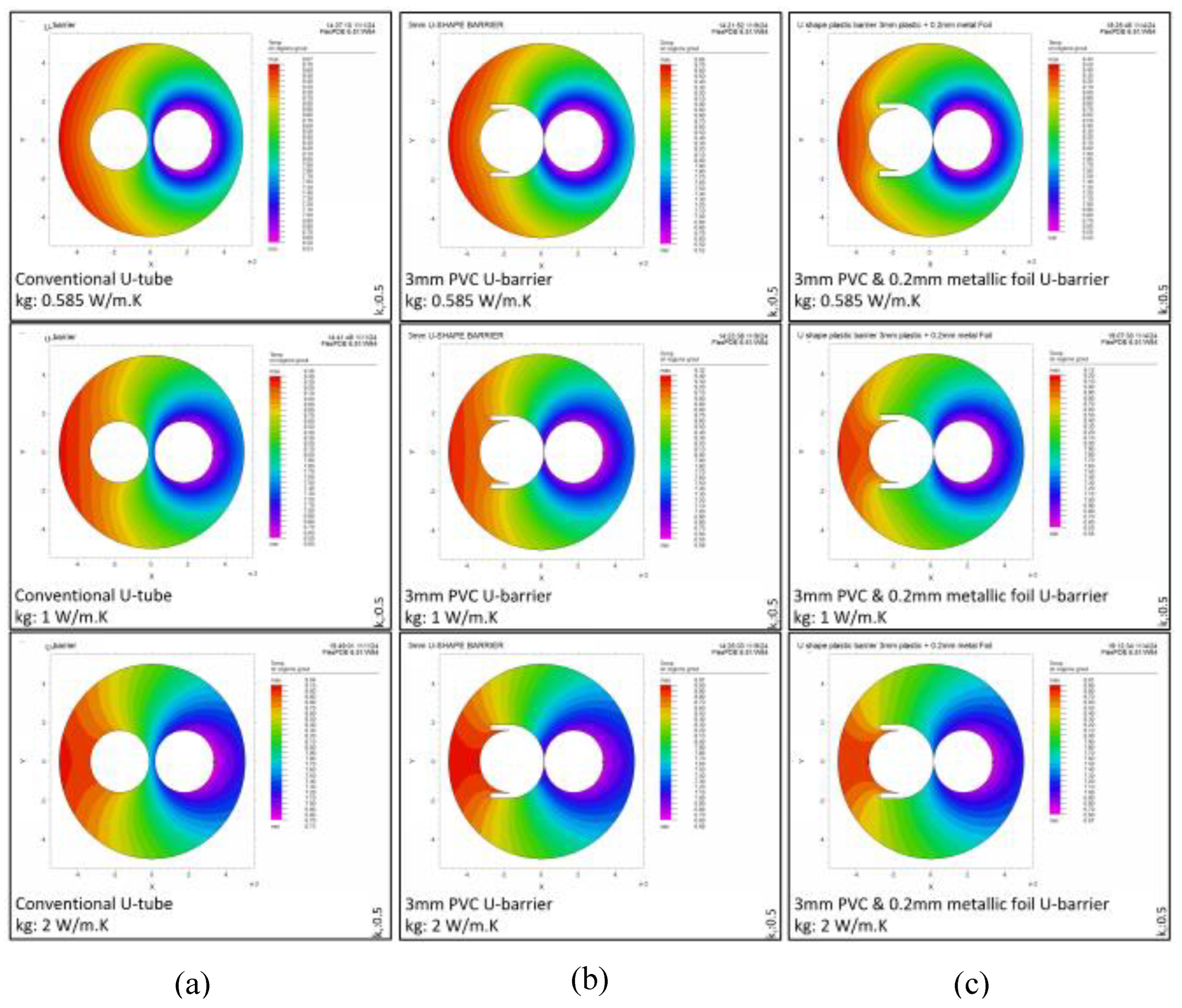
Figure 25.
Temperature distribution for different grouts at minimum shank spacing and soil thermal conductivity of 1 W/m.K for (a) Conventional U-tube (b) 3mm PVC plastic U-barrier & (c) 3mm PVC plastic U-barrier with 0.2mm self-adhesive metal tape.
Figure 25.
Temperature distribution for different grouts at minimum shank spacing and soil thermal conductivity of 1 W/m.K for (a) Conventional U-tube (b) 3mm PVC plastic U-barrier & (c) 3mm PVC plastic U-barrier with 0.2mm self-adhesive metal tape.
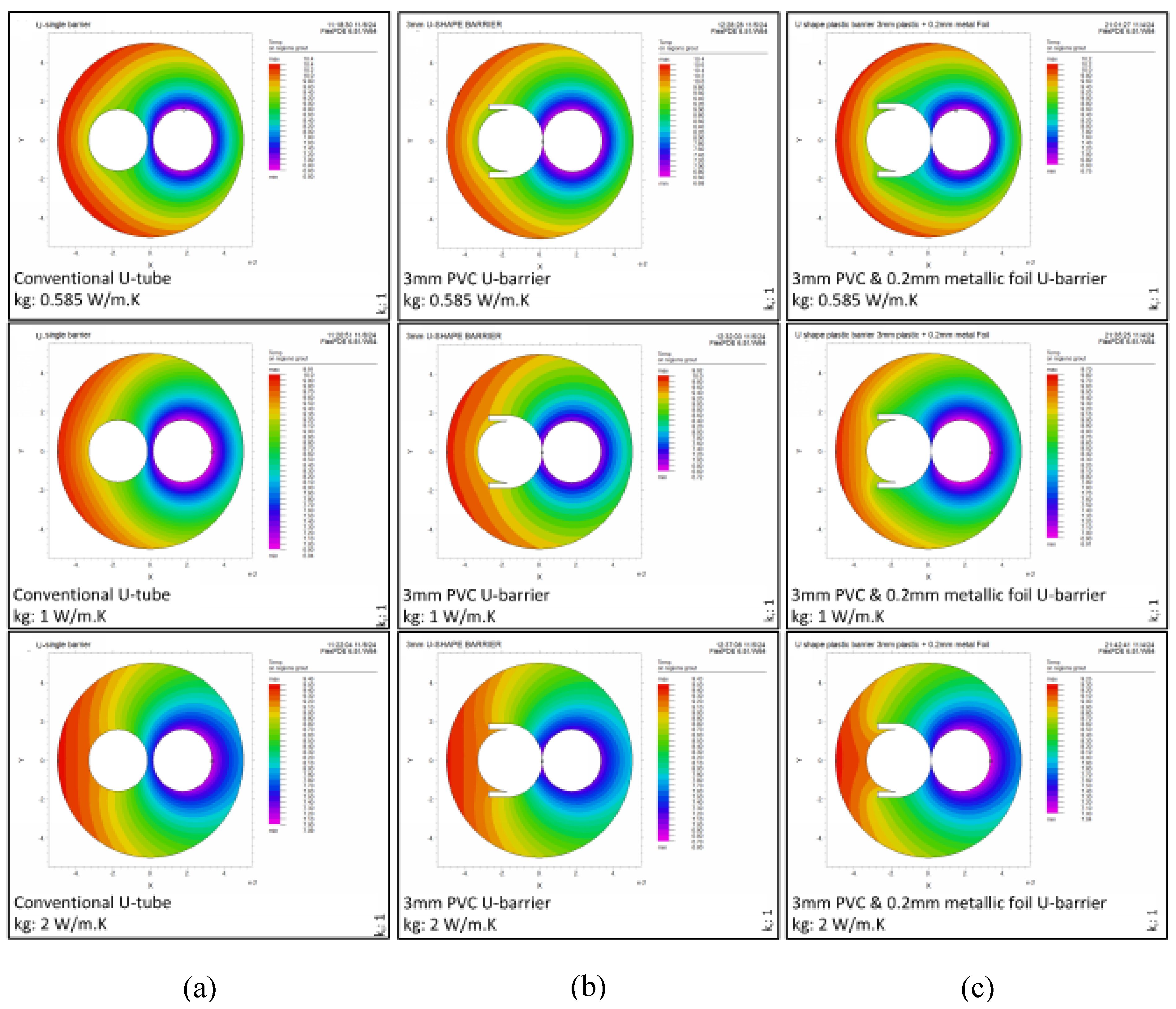
Figure 26.
Temperature distribution for different grouts at minimum shank spacing and soil thermal conductivity of 2 W/m.K for (a) Conventional U-tube (b) 3mm PVC plastic U-barrier & (c) 3mm PVC plastic U-barrier with 0.2mm self-adhesive metal tape.
Figure 26.
Temperature distribution for different grouts at minimum shank spacing and soil thermal conductivity of 2 W/m.K for (a) Conventional U-tube (b) 3mm PVC plastic U-barrier & (c) 3mm PVC plastic U-barrier with 0.2mm self-adhesive metal tape.
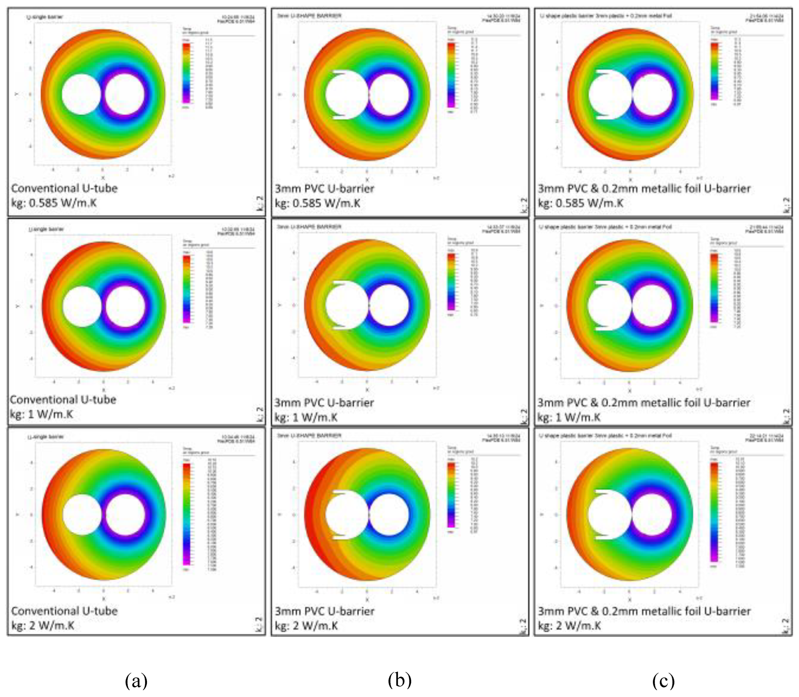
Figure 27.
Reduction in the BHX length for various single U- barriers- Soil thermal conductivity: 0.5 W/m.K.
Figure 27.
Reduction in the BHX length for various single U- barriers- Soil thermal conductivity: 0.5 W/m.K.
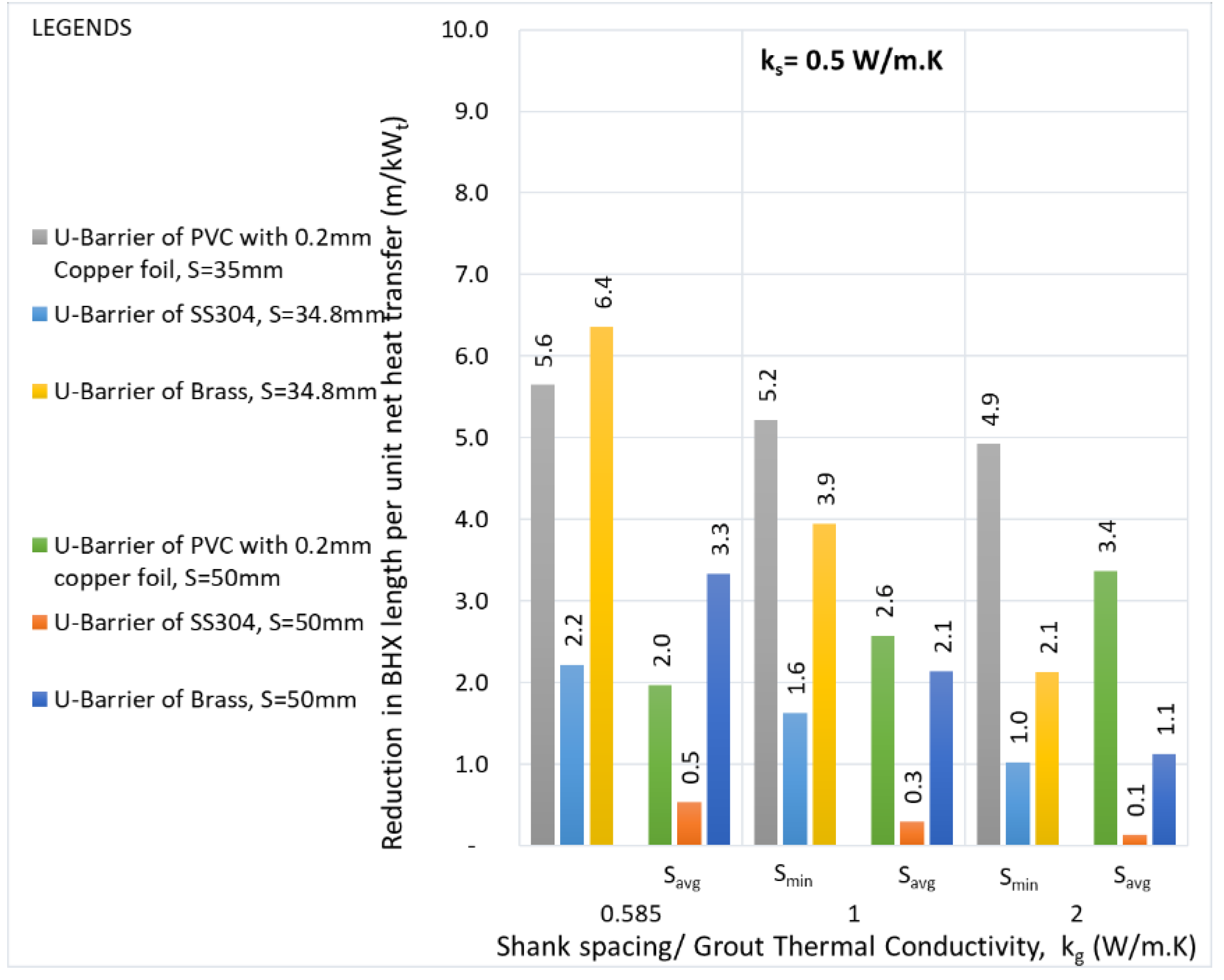
Figure 28.
Reduction in the BHX length for various single U- barriers- Soil thermal conductivity: 1 W/m.K.
Figure 28.
Reduction in the BHX length for various single U- barriers- Soil thermal conductivity: 1 W/m.K.
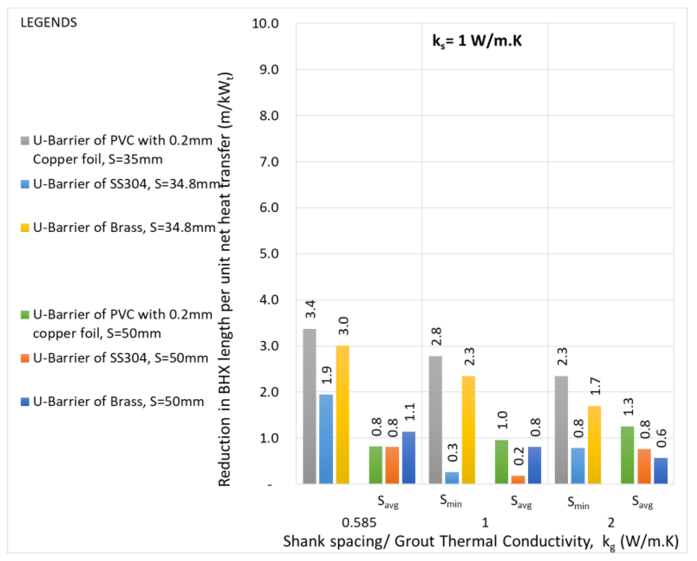
Figure 29.
Reduction in the BHX length for various single U- barriers- Soil thermal conductivity: 2 W/m.K.
Figure 29.
Reduction in the BHX length for various single U- barriers- Soil thermal conductivity: 2 W/m.K.
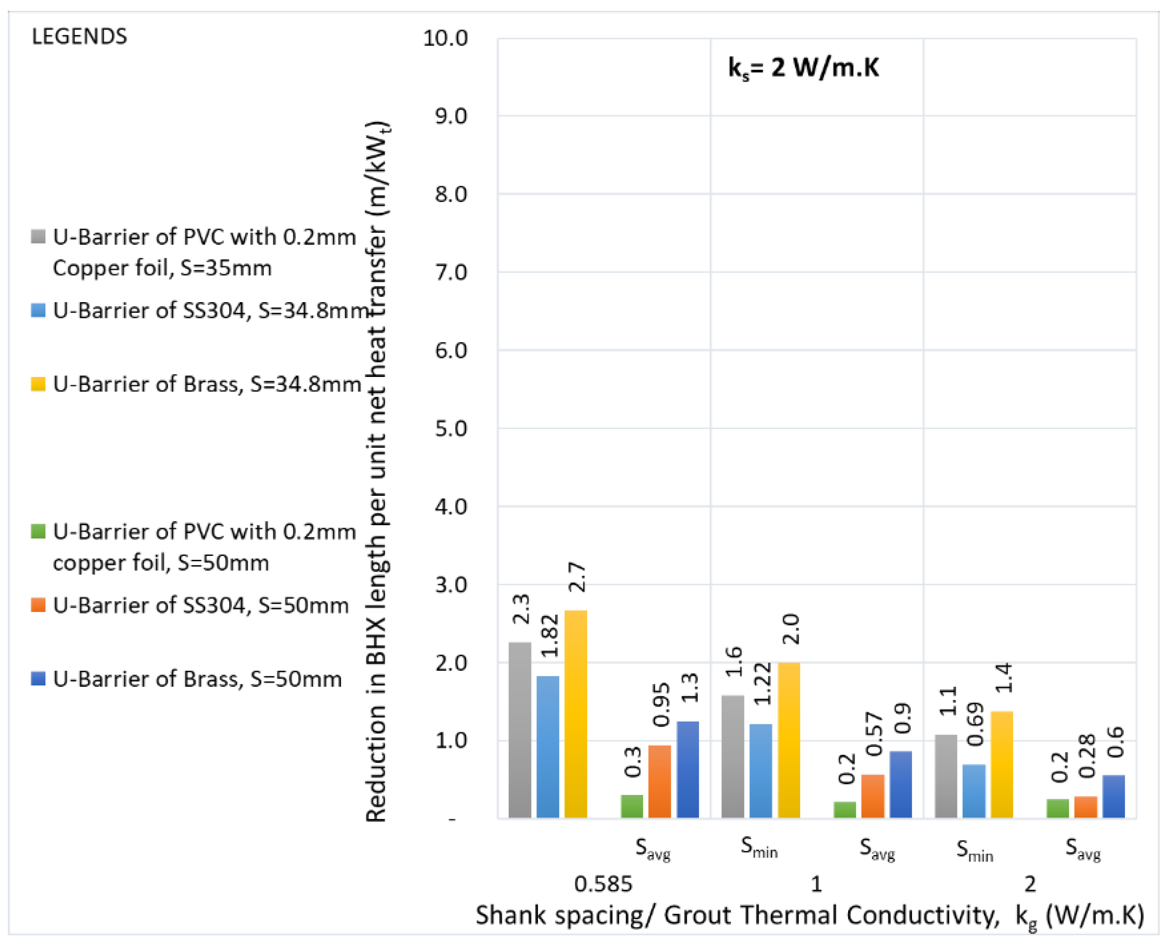
Figure 30.
Reduction in the BHX length for various U- barriers- Soil thermal conductivity: 0.5 W/m.K.
Figure 30.
Reduction in the BHX length for various U- barriers- Soil thermal conductivity: 0.5 W/m.K.
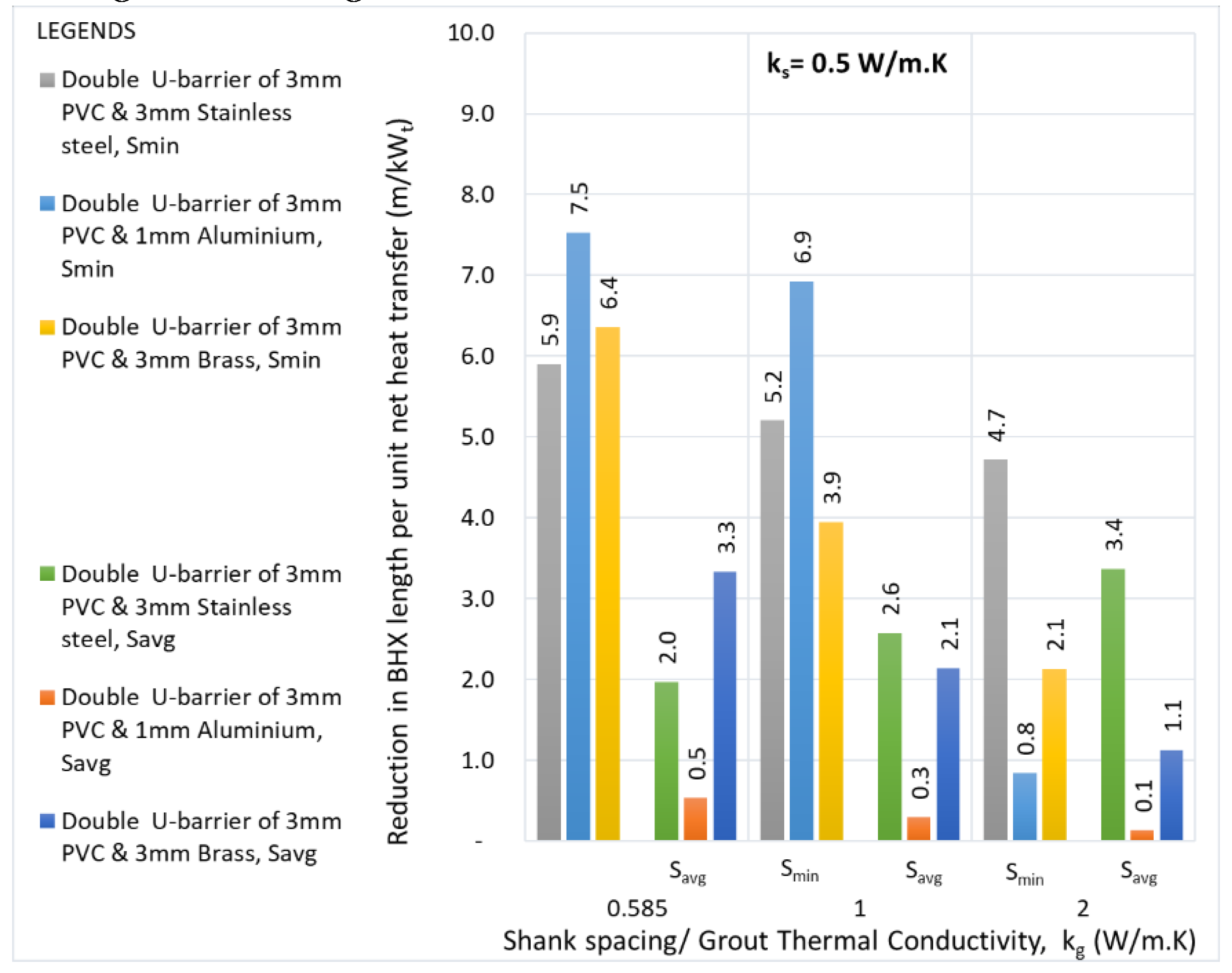
Figure 31.
Reduction in the BHX length for various U- barriers- Soil thermal conductivity: 1 W/m.K.
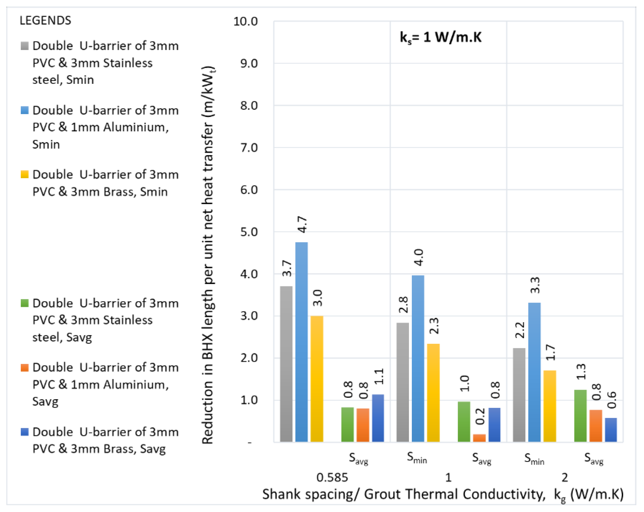
Figure 32.
Reduction in the BHX length for various U- barriers- Soil thermal conductivity: 2 W/m.K.
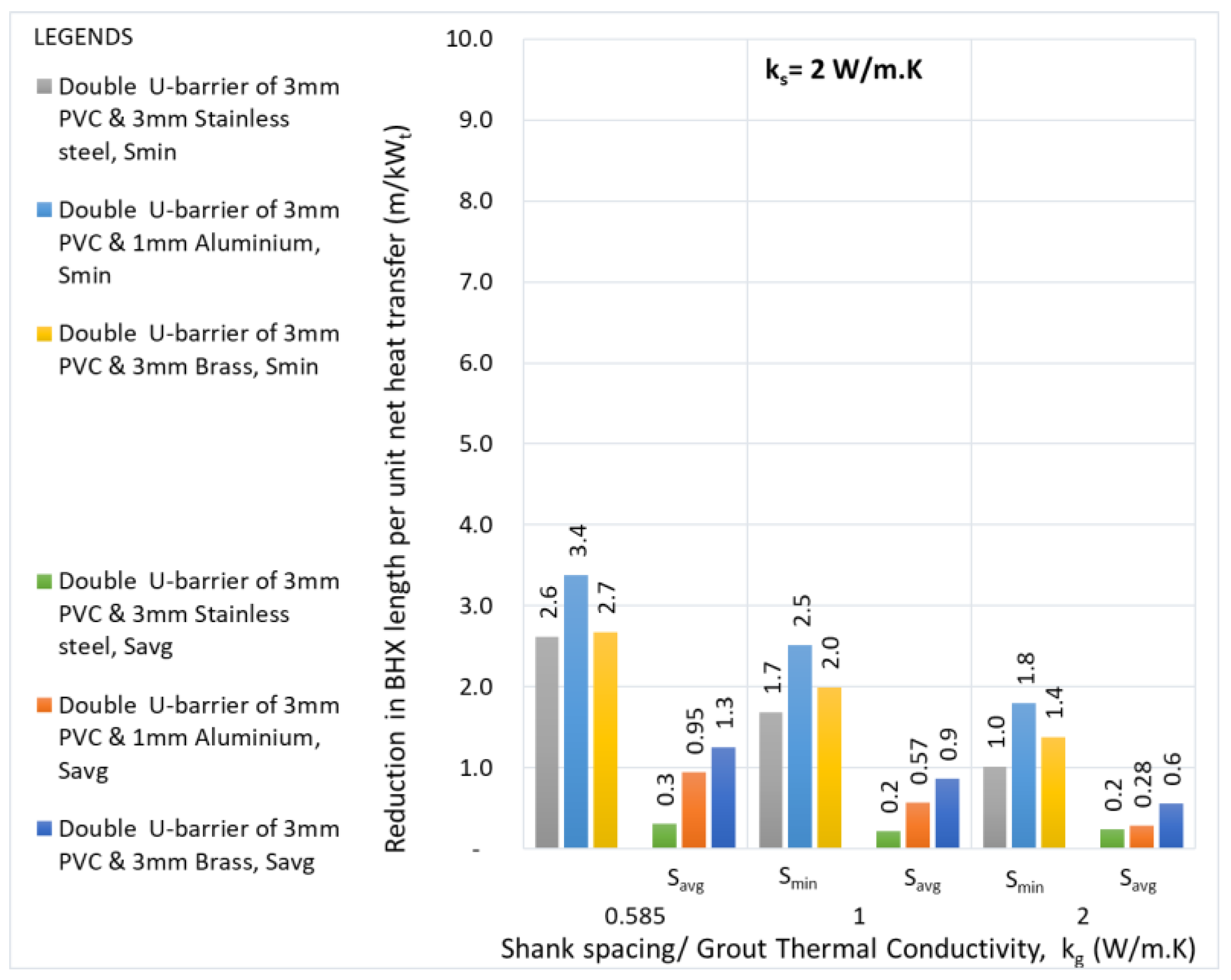
Figure 33.
Temperature distribution for different grouts at minimum shank spacing and soil thermal conductivity of 0.5 W/m.K for (a) Conventional U-tube (b) 3mm PVC & 3mm brass double U- barrier.
Figure 33.
Temperature distribution for different grouts at minimum shank spacing and soil thermal conductivity of 0.5 W/m.K for (a) Conventional U-tube (b) 3mm PVC & 3mm brass double U- barrier.
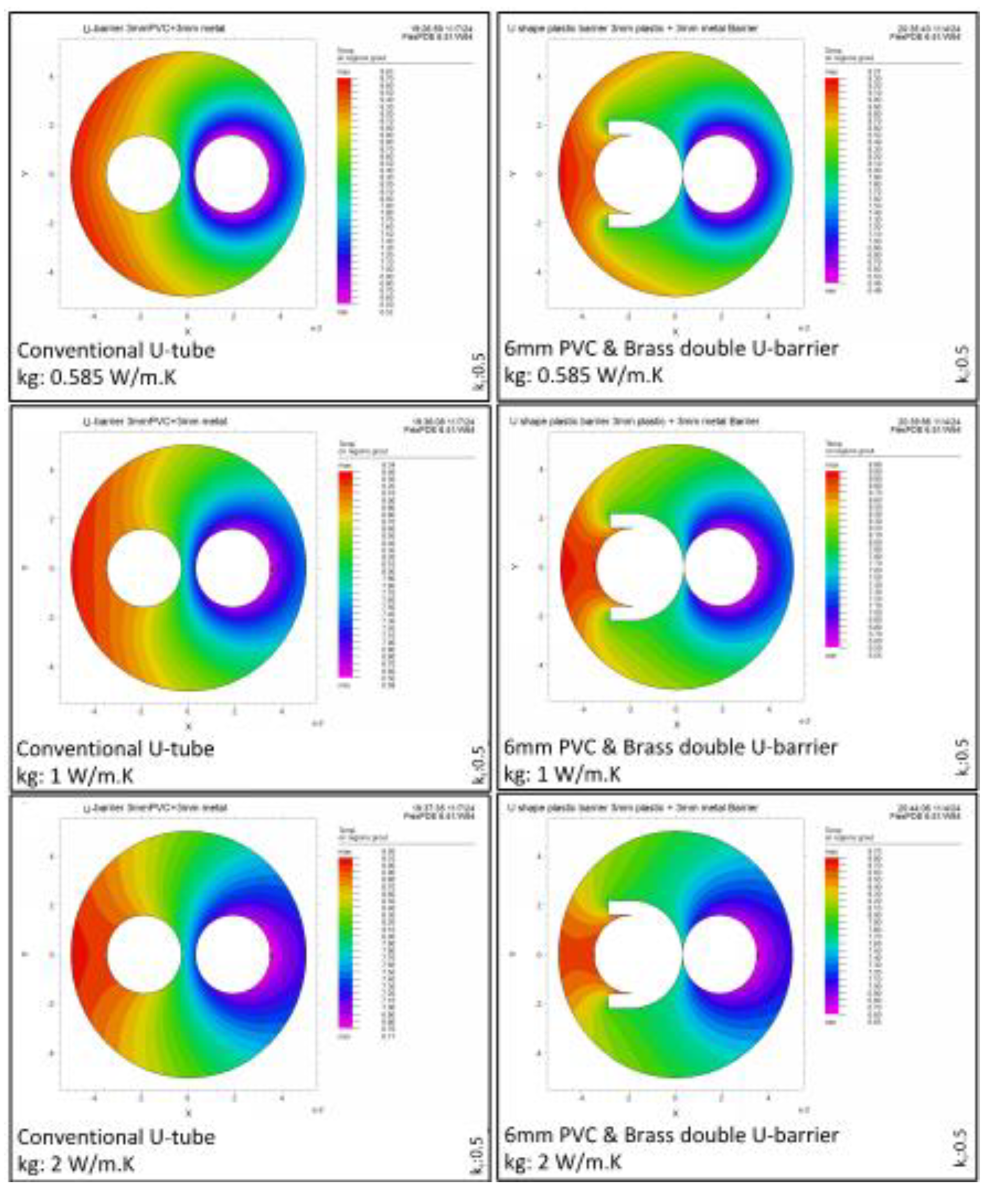
Figure 34.
Temperature distribution for different grouts at minimum shank spacing and soil thermal conductivity of 1 W/m.K for (a) Conventional U-tube (b) 3mm PVC & 3mm brass double U- barrier.
Figure 34.
Temperature distribution for different grouts at minimum shank spacing and soil thermal conductivity of 1 W/m.K for (a) Conventional U-tube (b) 3mm PVC & 3mm brass double U- barrier.

Figure 35.
Temperature distribution for different grouts at minimum shank spacing and soil thermal conductivity of 2 W/m.K for (a) Conventional U-tube (b) 3mm PVC & 3mm brass double U- barrier.
Figure 35.
Temperature distribution for different grouts at minimum shank spacing and soil thermal conductivity of 2 W/m.K for (a) Conventional U-tube (b) 3mm PVC & 3mm brass double U- barrier.
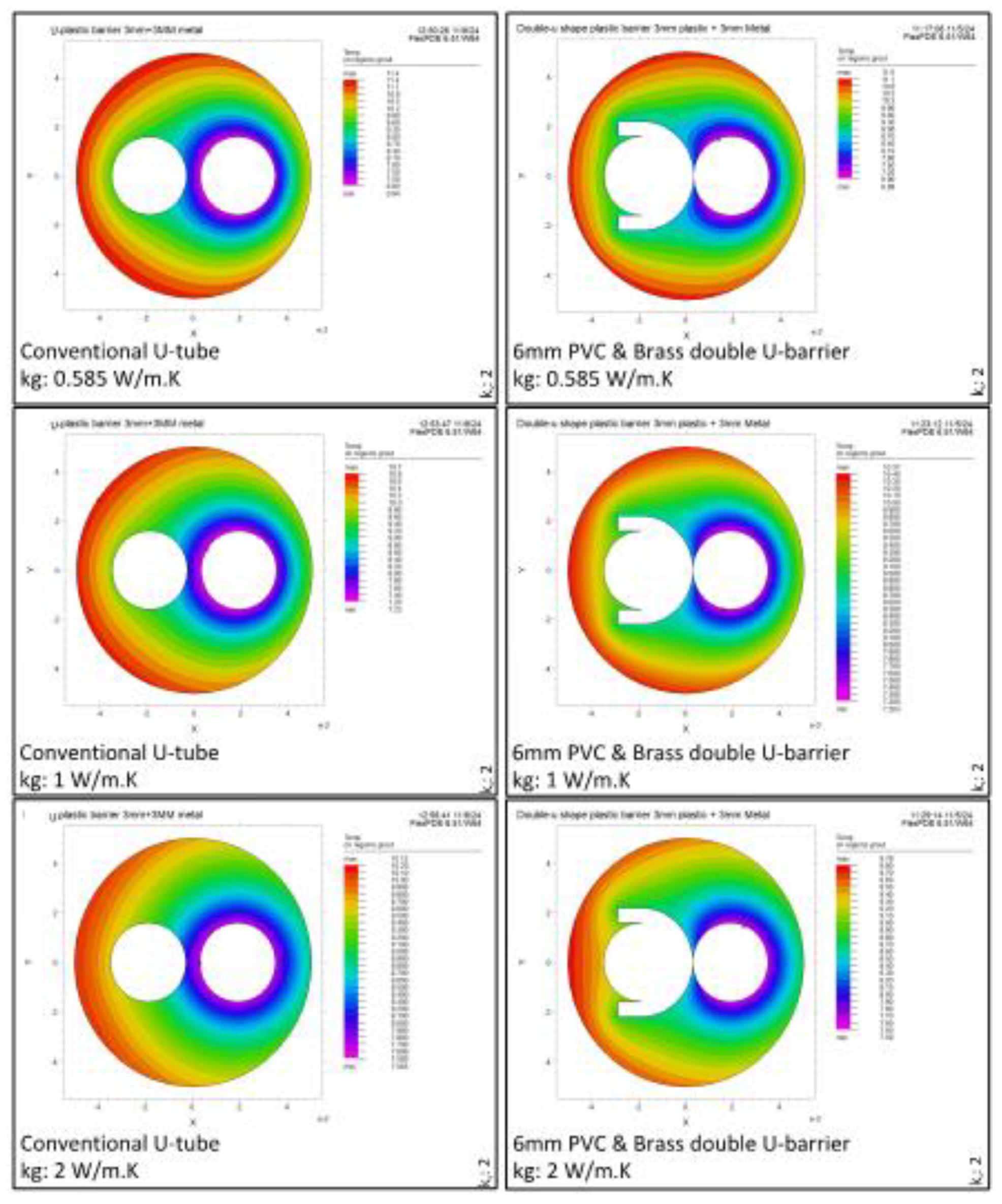
Figure 36.
Required BHX length for soil thermal conductivity of 0.5 W/m.K.

Figure 37.
Required BHX length for soil thermal conductivity of 1 W/m.K.
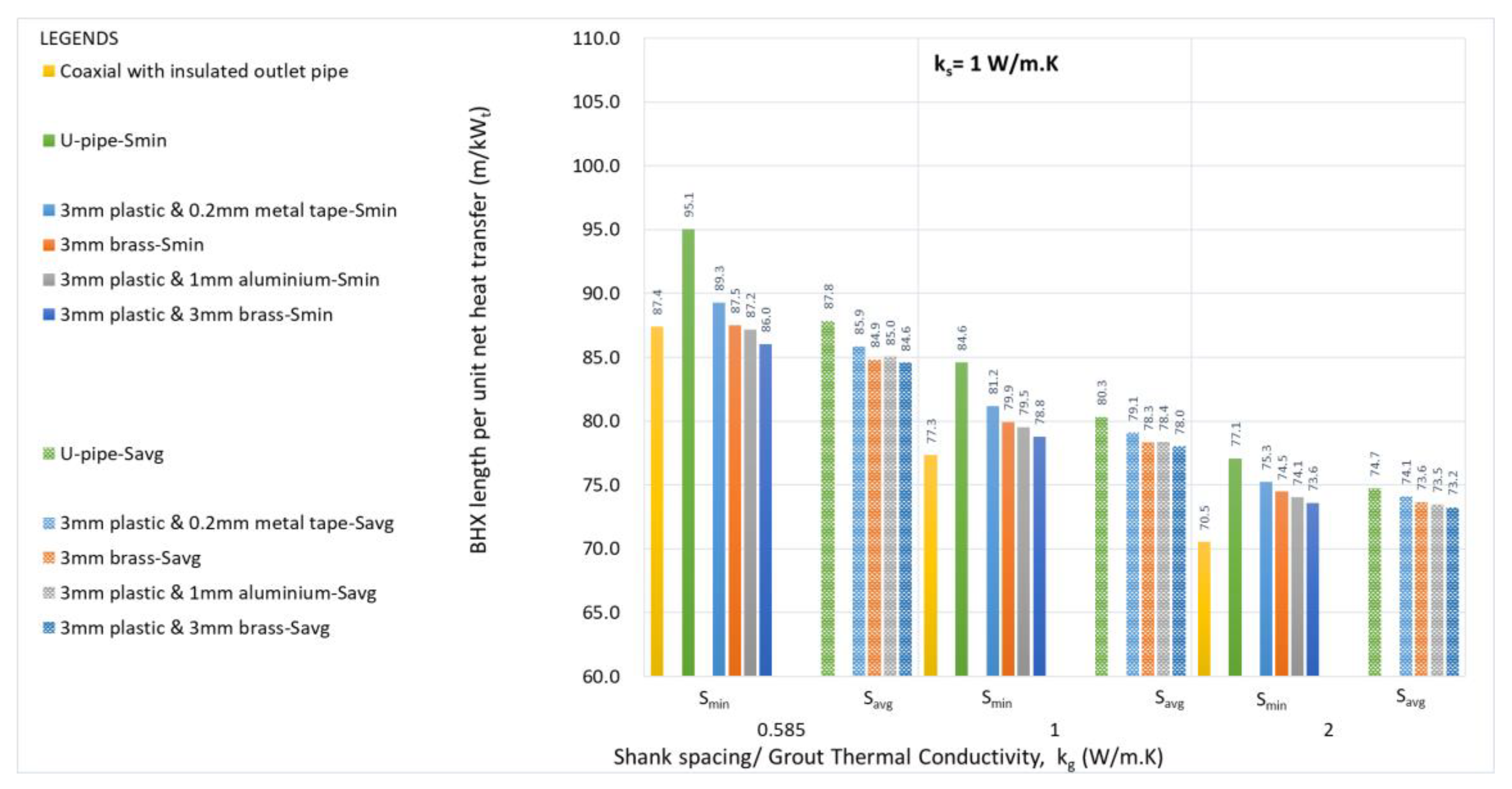
Figure 38.
Required BHX length for soil thermal conductivity of 2 W/m.K.
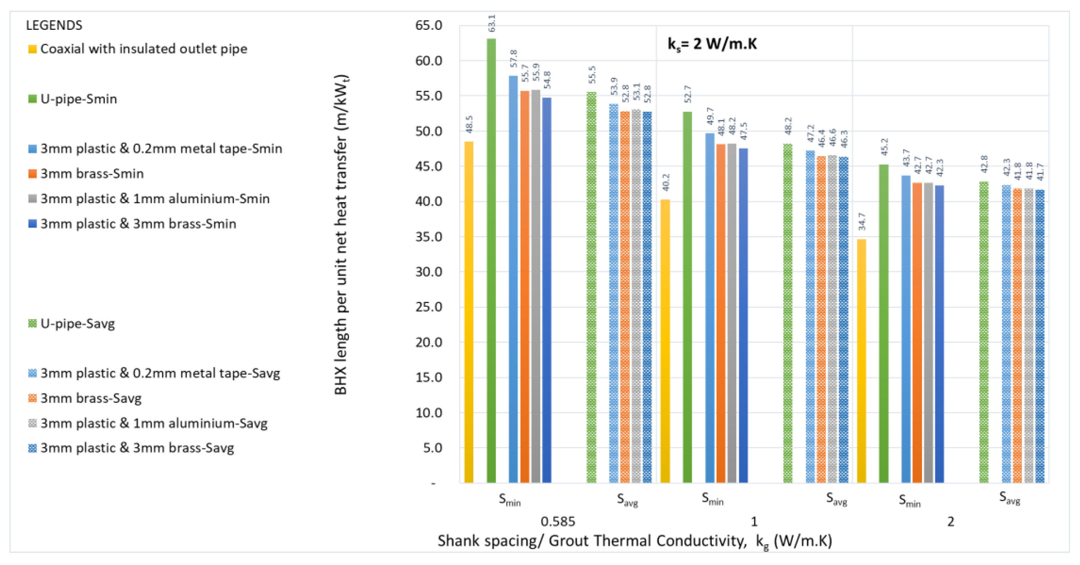
Table 1.
U-tube model Parameters.
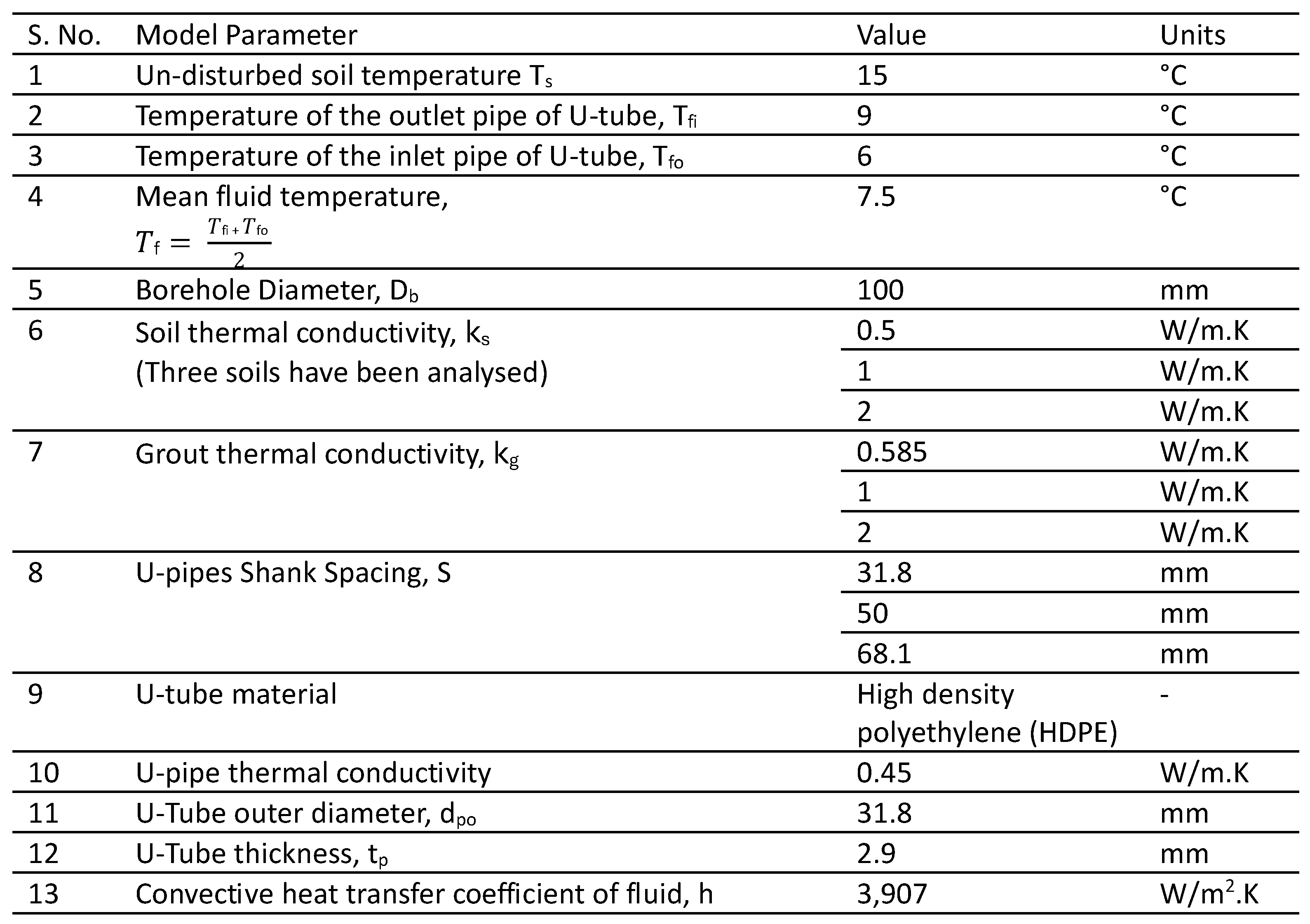
Table 2.
Validation results for FlexPDE analysis.
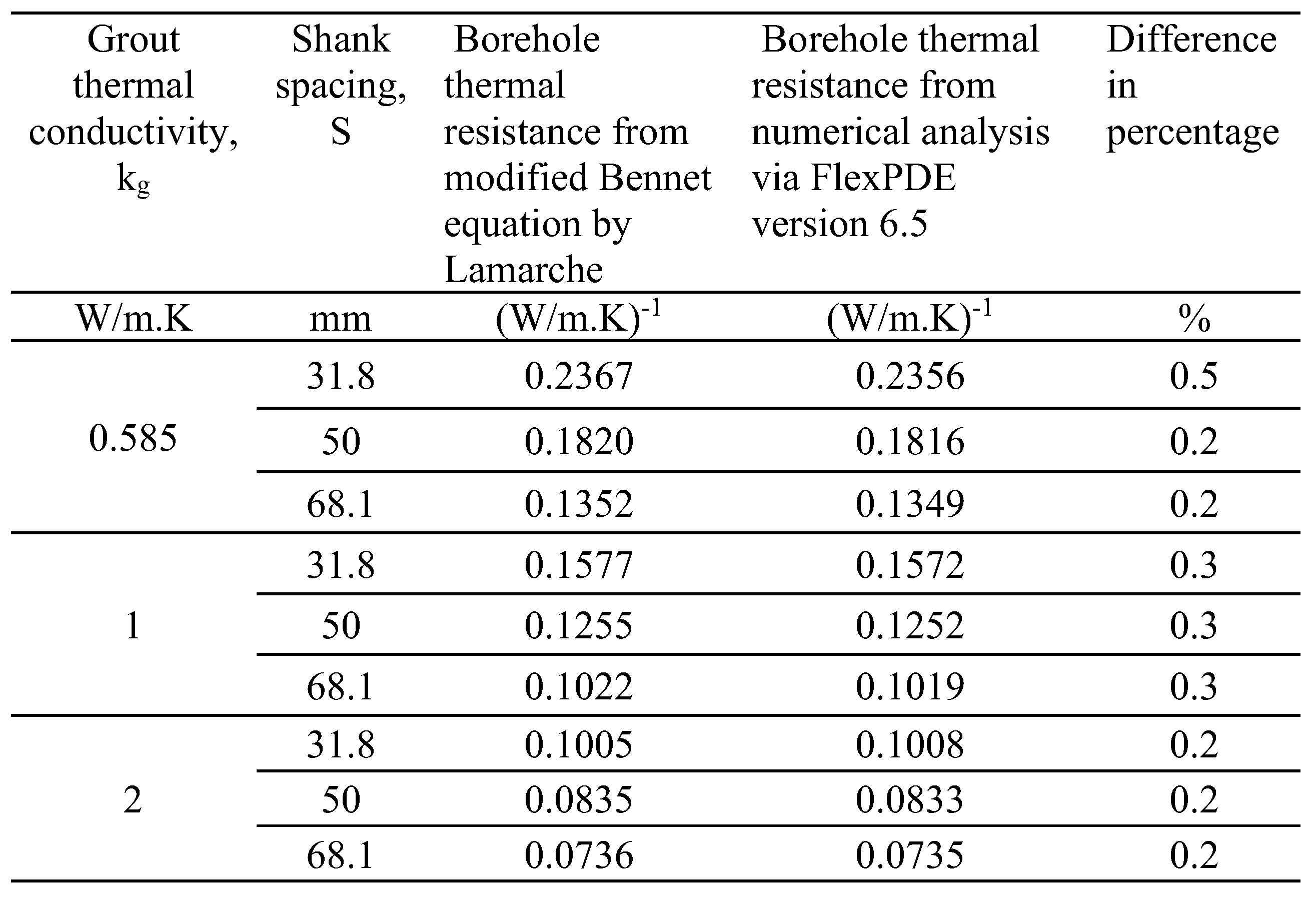
Table 3.
Coaxial pipes arrangement model parameters.
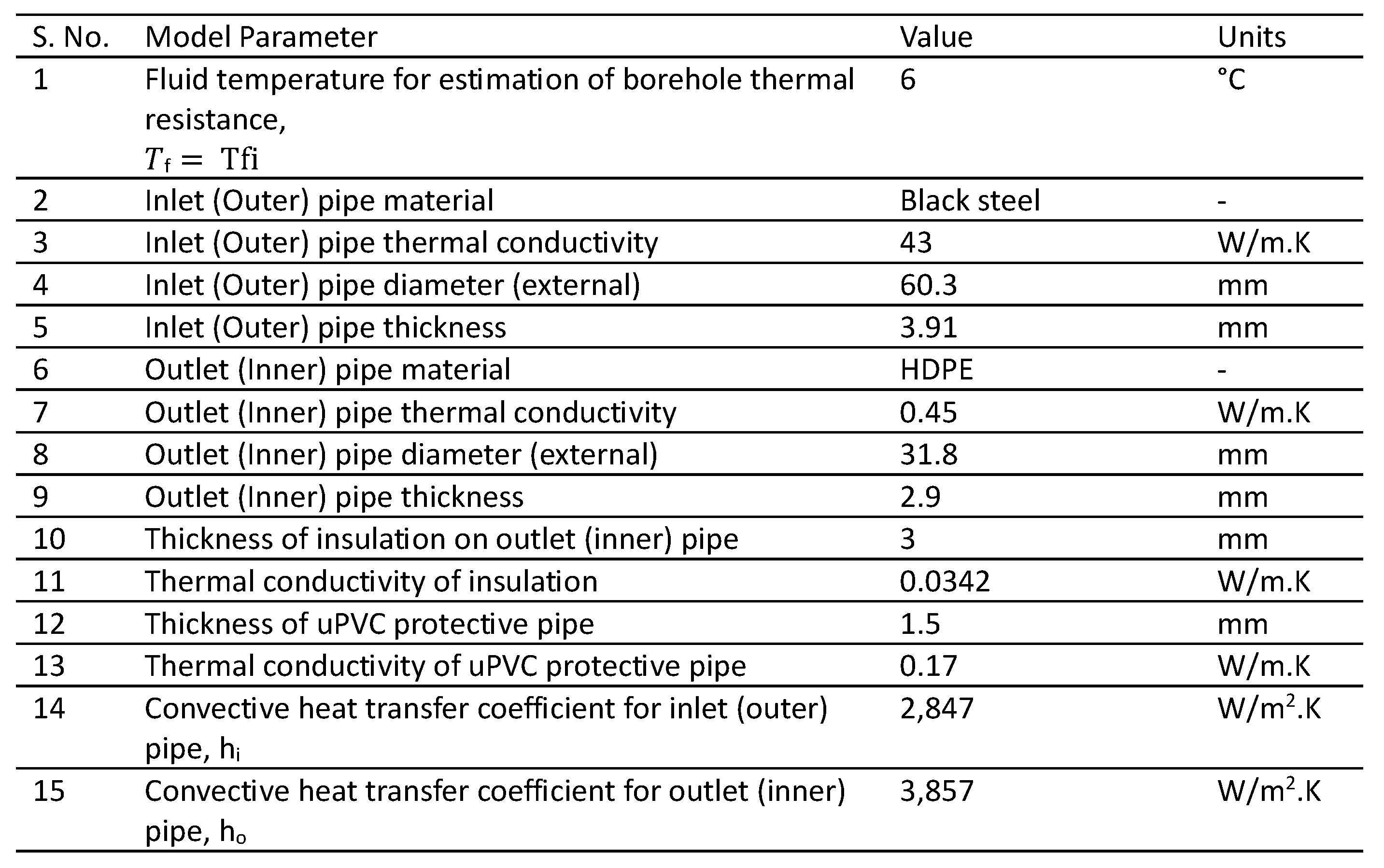
Table 4.
BHX thermal resistance and heat transfer for flat plate plastic barrier at soil thermal conductivity of 1 W/m.K.
Table 4.
BHX thermal resistance and heat transfer for flat plate plastic barrier at soil thermal conductivity of 1 W/m.K.
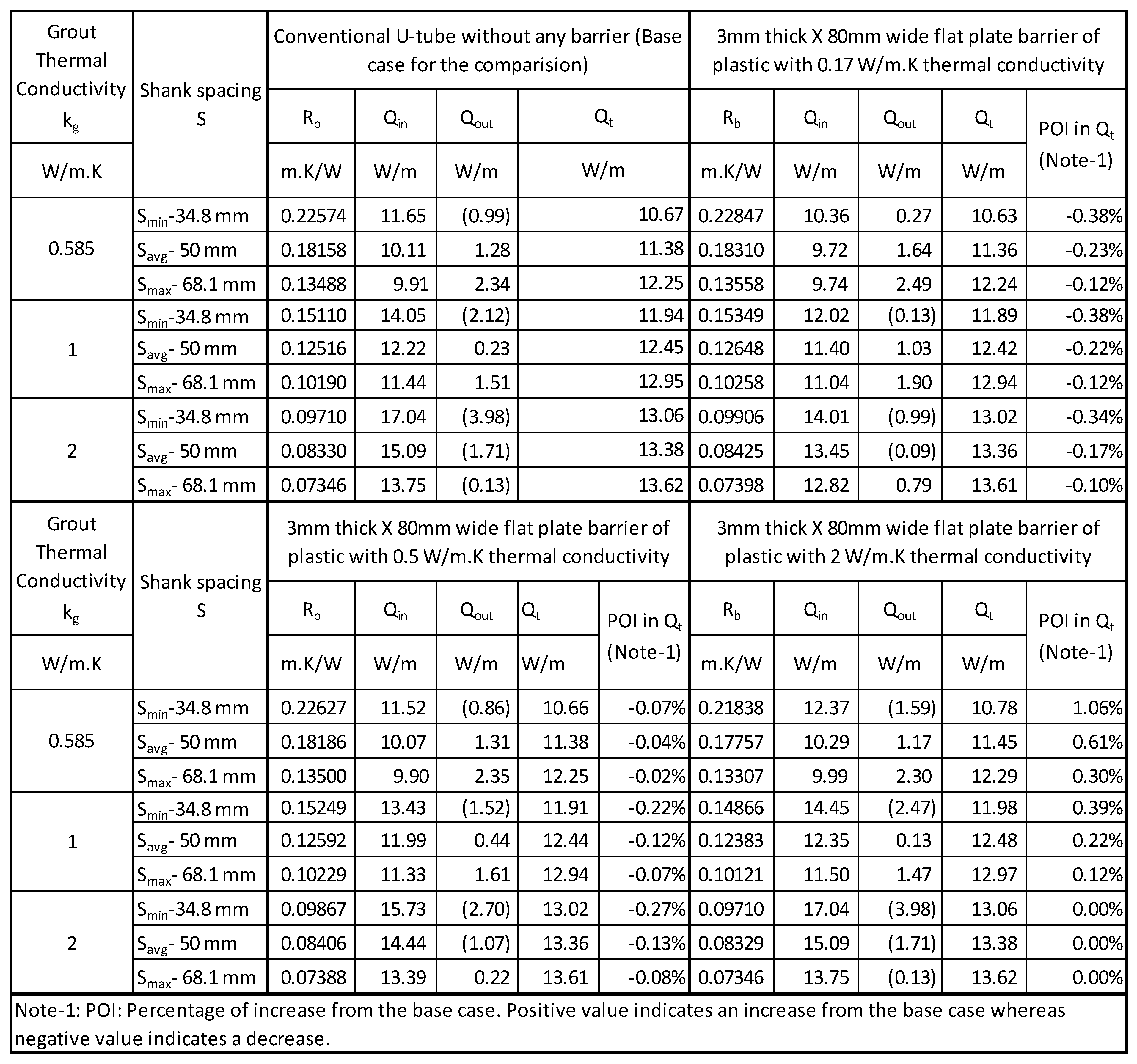
Table 5.
Comparison of heat transfer for flat plate plastic barrier with flat plate plastic barrier with 0.2mm metallic tape at soil thermal conductivity of 1 W/m.K.
Table 5.
Comparison of heat transfer for flat plate plastic barrier with flat plate plastic barrier with 0.2mm metallic tape at soil thermal conductivity of 1 W/m.K.
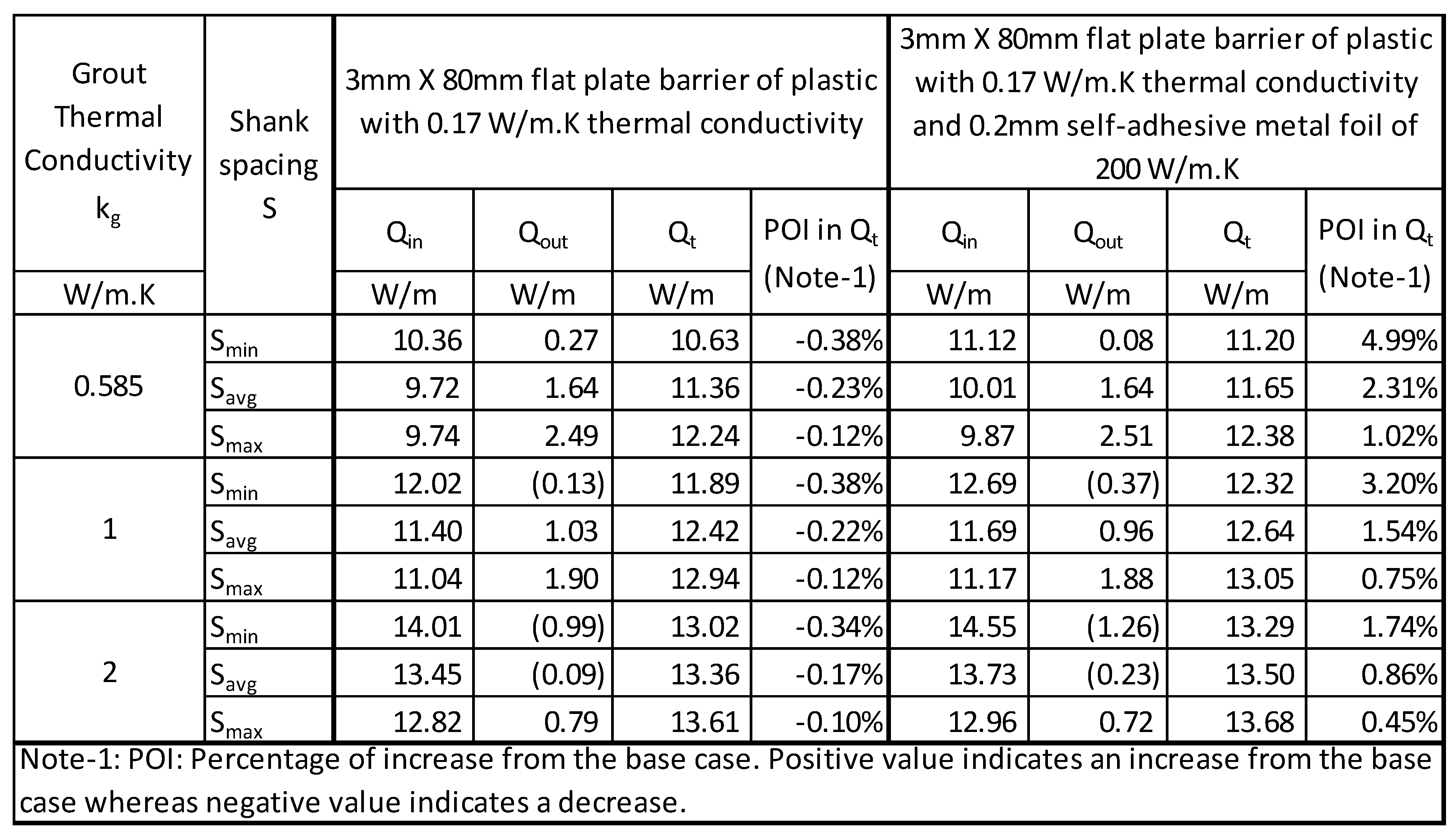
Table 6.
Temperature in the BHX as shown in Figure 12, at few locations in different scenarios for minimum shank spacing.
Table 6.
Temperature in the BHX as shown in Figure 12, at few locations in different scenarios for minimum shank spacing.
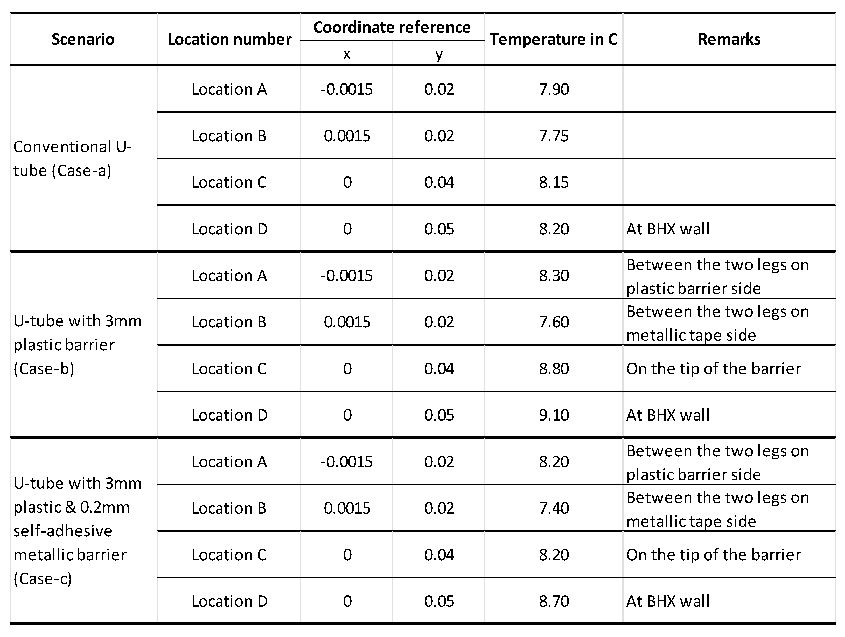
Table 7.
BHX heat transfer for flat plate metallic barrier at soil thermal conductivity of 1 W/m.K.
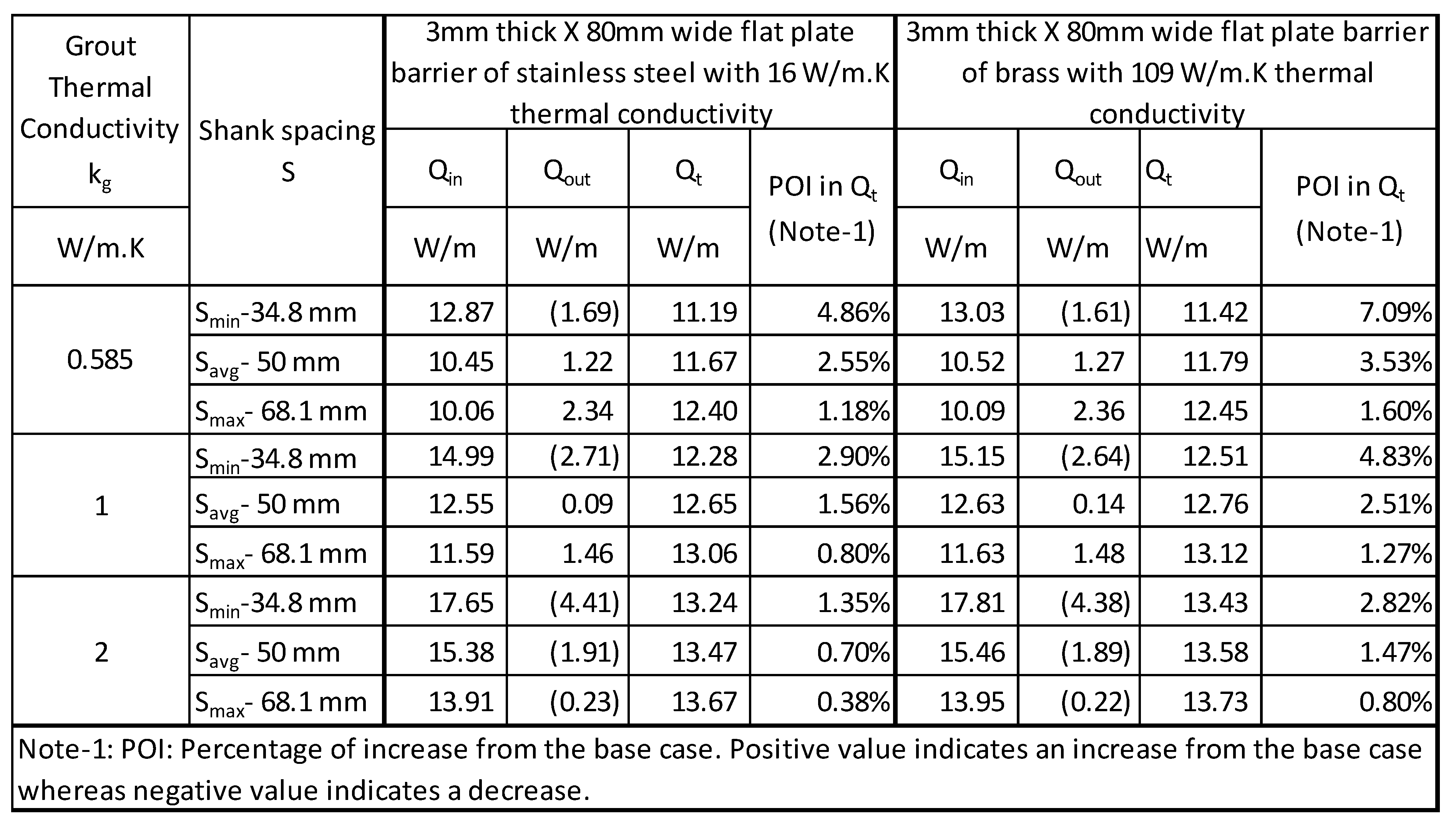
Table 8.
Length of BHX- Single flat plate barrier.
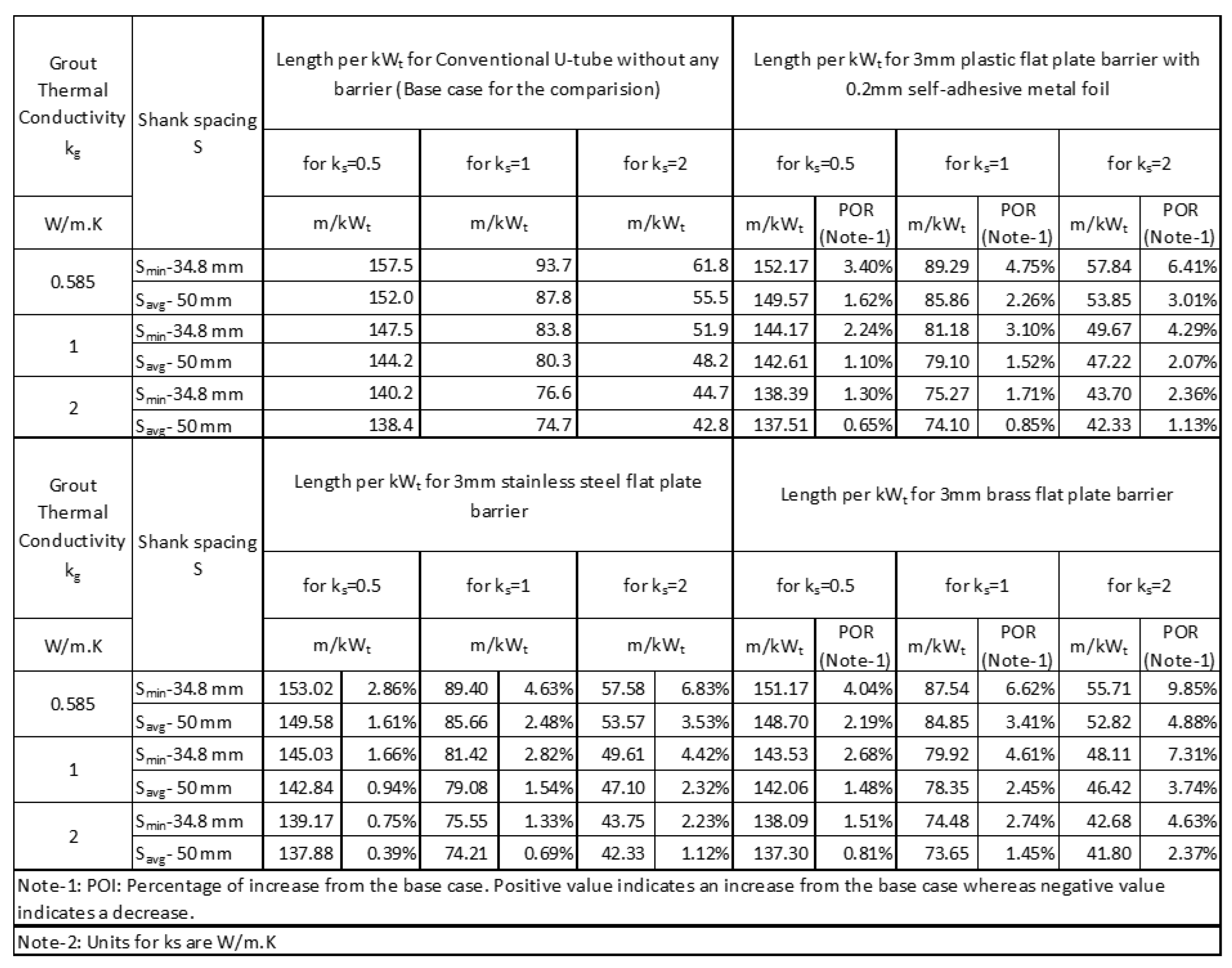
Table 10.
BHX heat transfer for 6mm double flat plate barrier at soil thermal conductivity of 1 W/m.K.
Table 10.
BHX heat transfer for 6mm double flat plate barrier at soil thermal conductivity of 1 W/m.K.
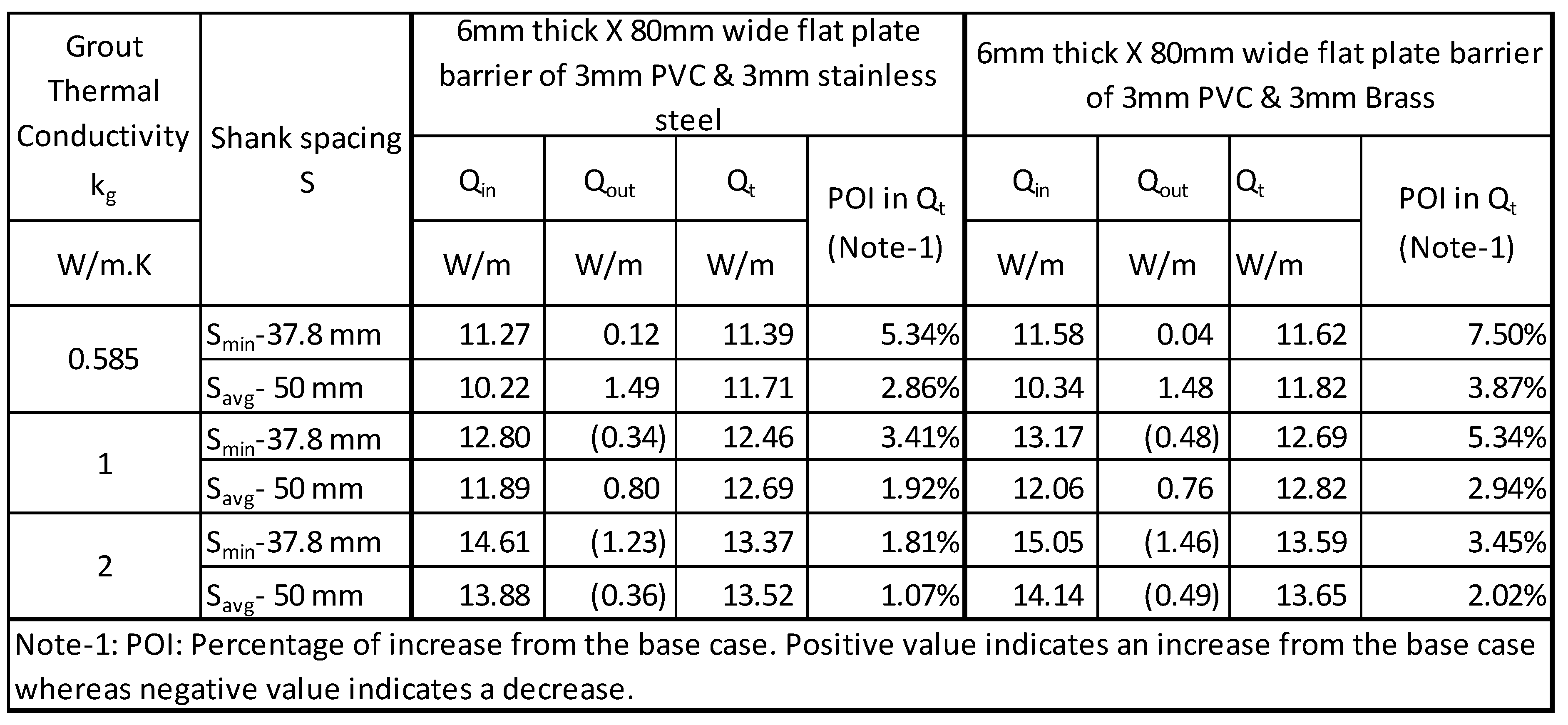
Table 11.
Length of BHX- 4mm double flat plate barrier (PVC & aluminium).
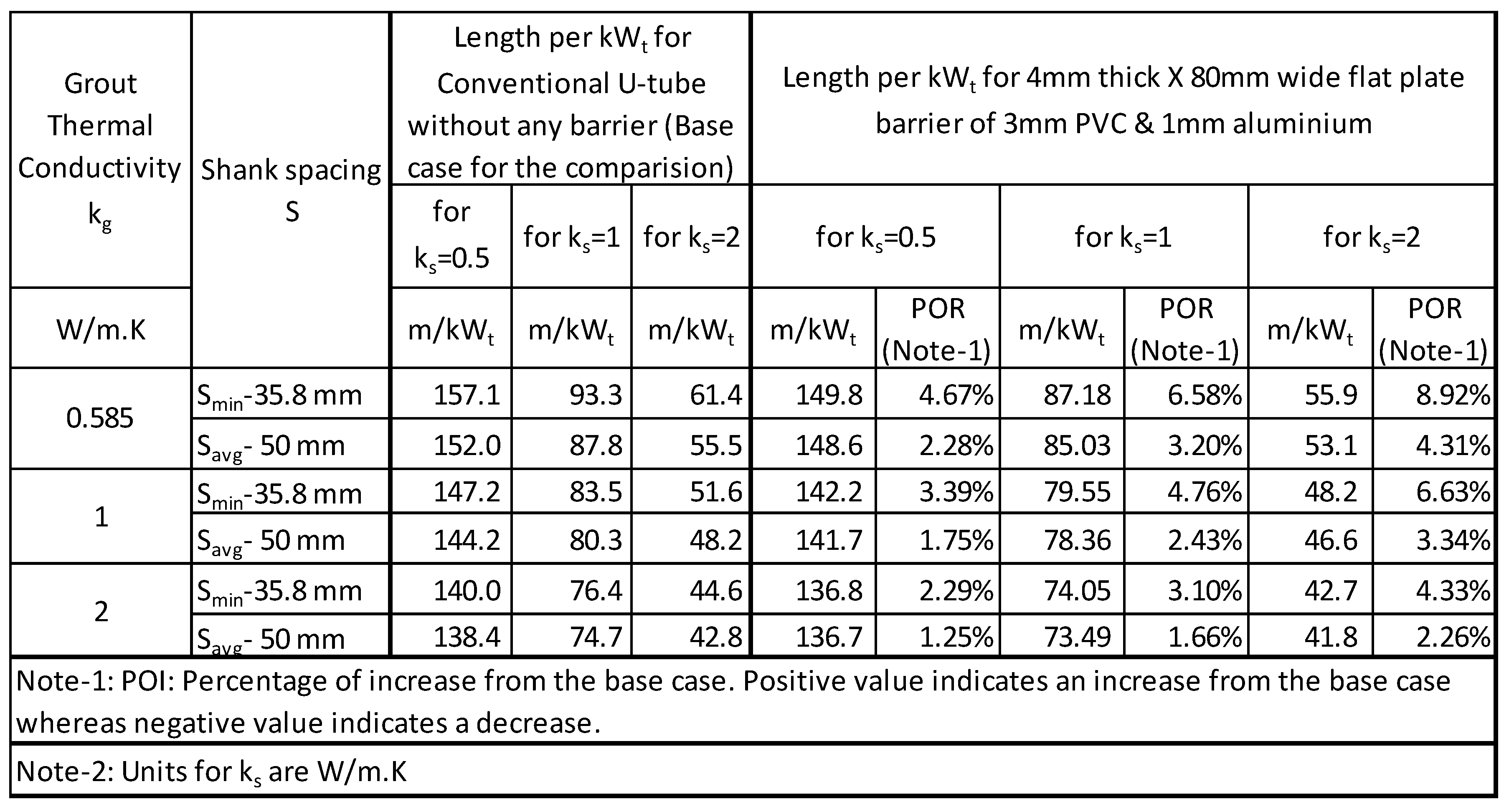
Table 12.
Length of BHX- 6mm double flat plate barrier (PVC &stainless steel, PVC & Brass).
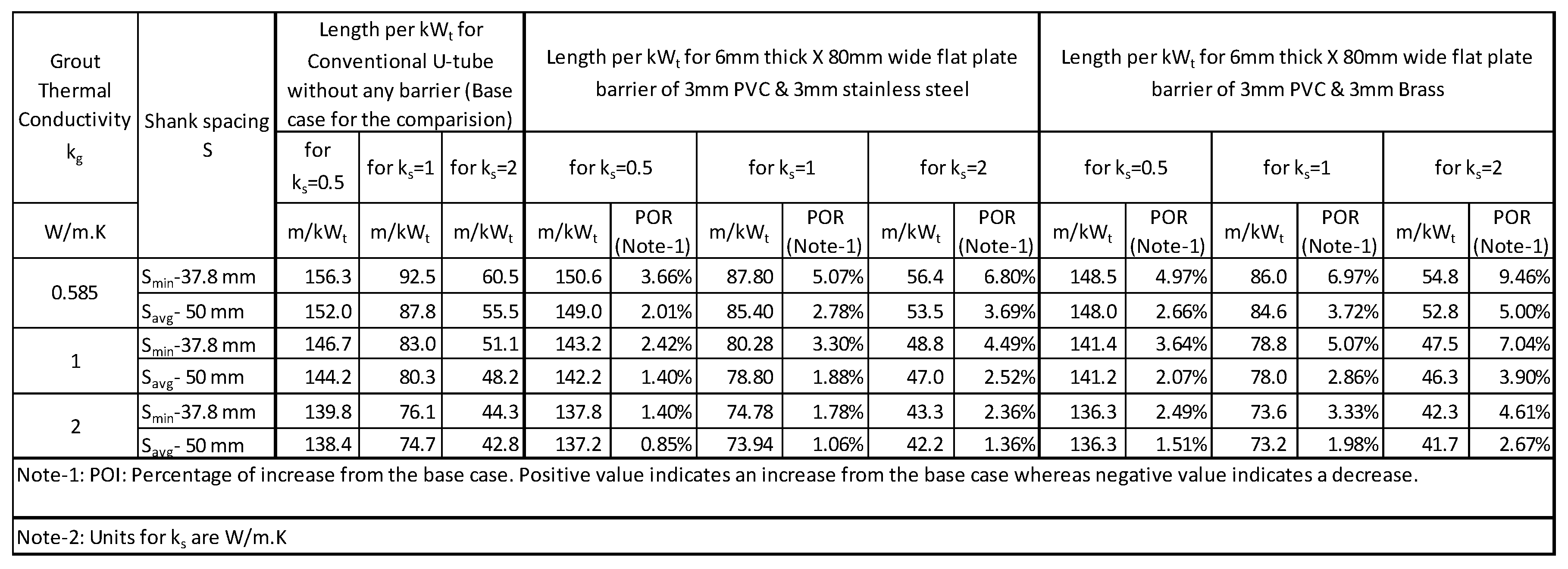
Table 13.
BHX thermal resistance and heat transfer for plastic U-barrier at soil thermal conductivity of 1 W/m.K.
Table 13.
BHX thermal resistance and heat transfer for plastic U-barrier at soil thermal conductivity of 1 W/m.K.
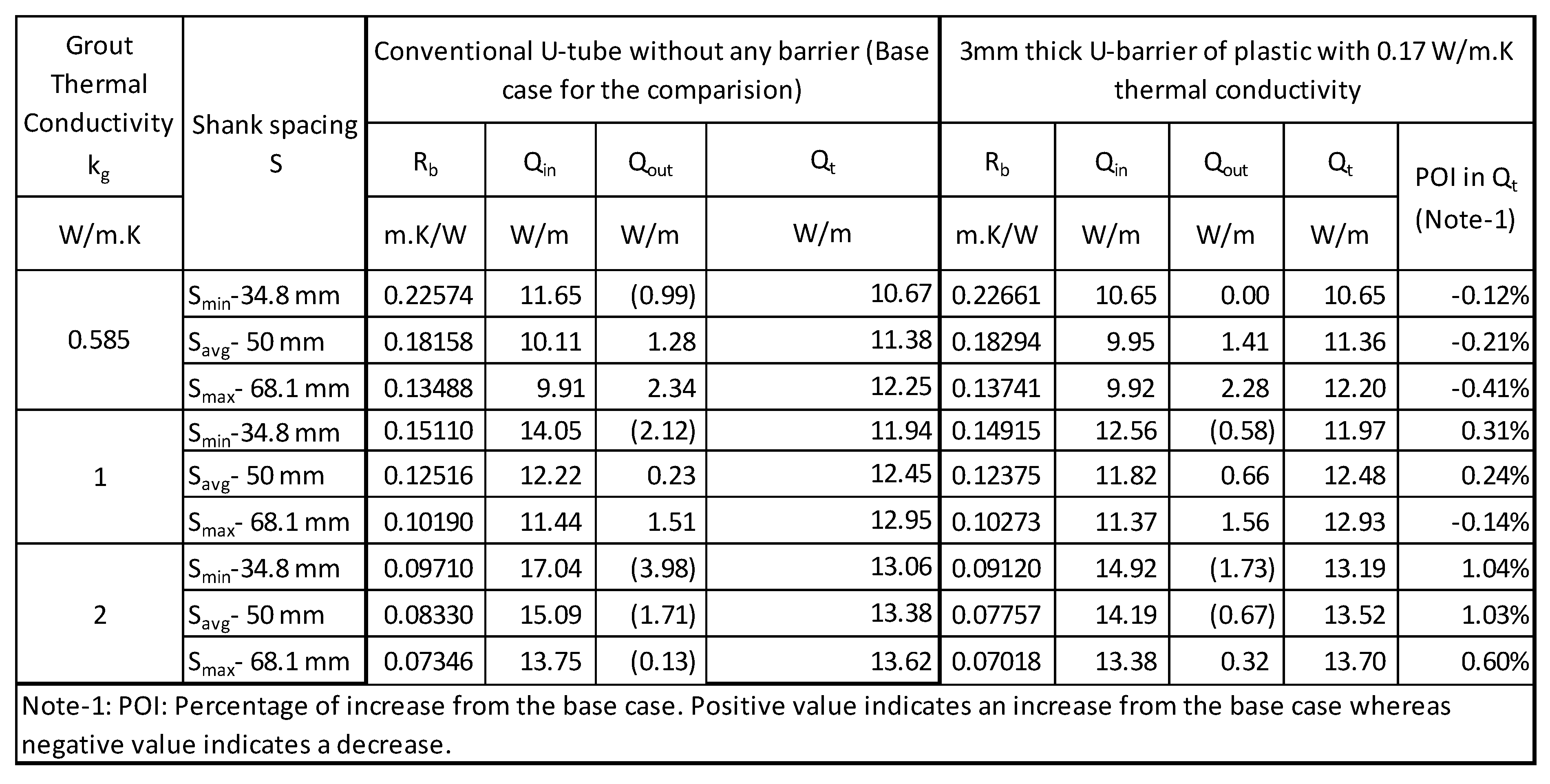
Table 14.
Comparison of heat transfer of plastic U-barrier with plastic U-barrier with 0.2mm metallic tape at soil thermal conductivity of 1 W/m.K.
Table 14.
Comparison of heat transfer of plastic U-barrier with plastic U-barrier with 0.2mm metallic tape at soil thermal conductivity of 1 W/m.K.
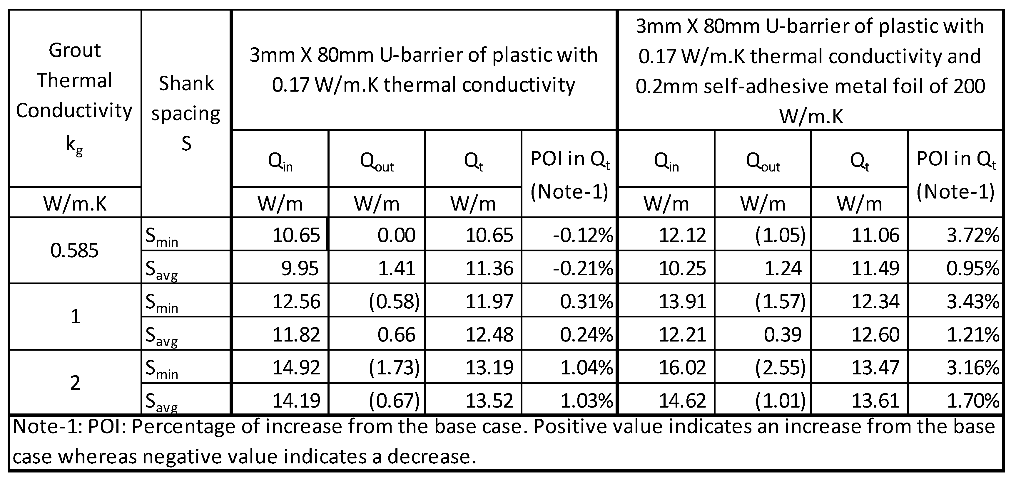
Table 15.
Temperature in the BHX as shown in Figure 24, at few locations in different scenarios for minimum shank spacing.
Table 15.
Temperature in the BHX as shown in Figure 24, at few locations in different scenarios for minimum shank spacing.
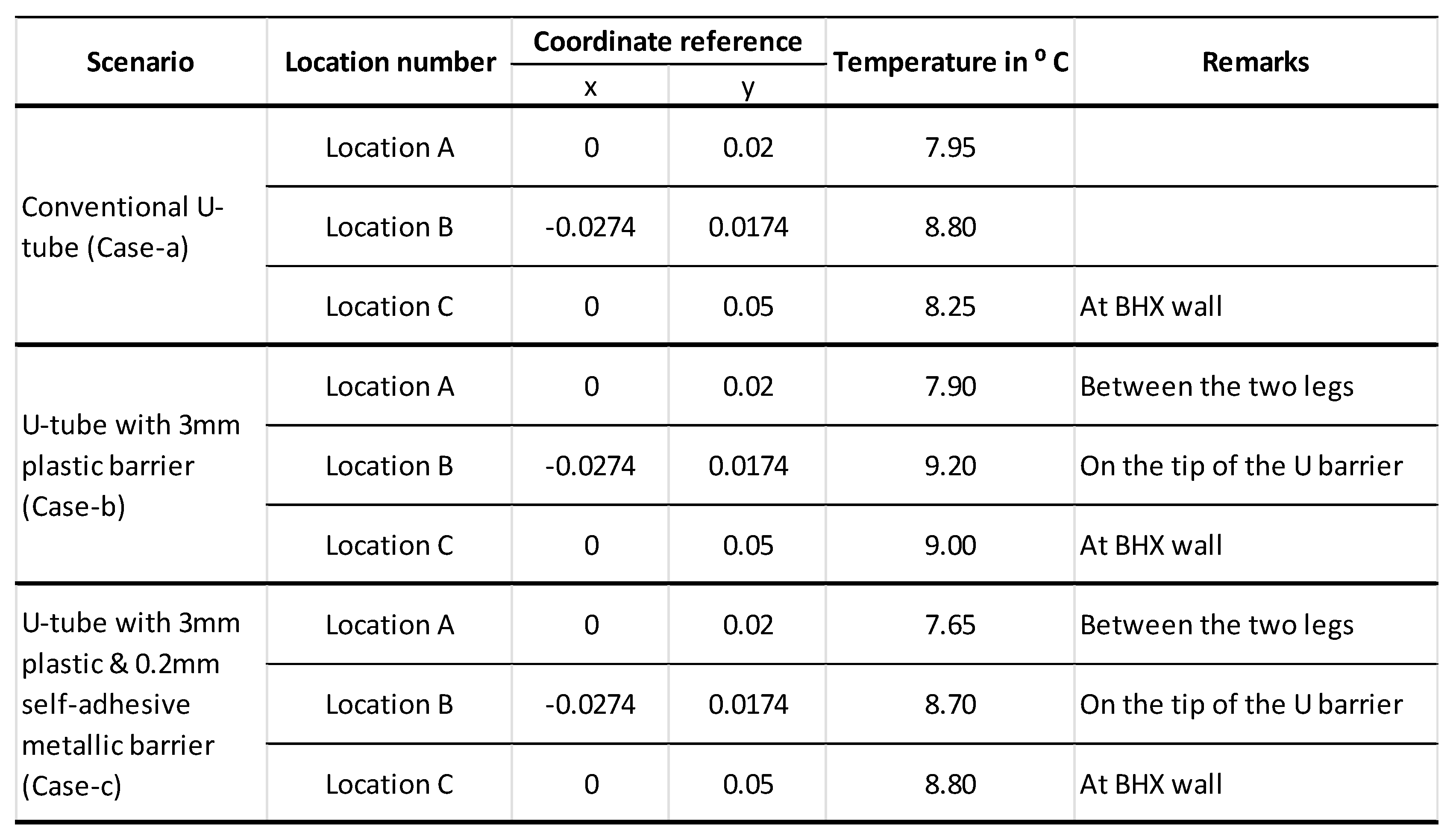
Table 16.
BHX heat transfer for metallic U-barrier at soil thermal conductivity of 1 W/m.K.
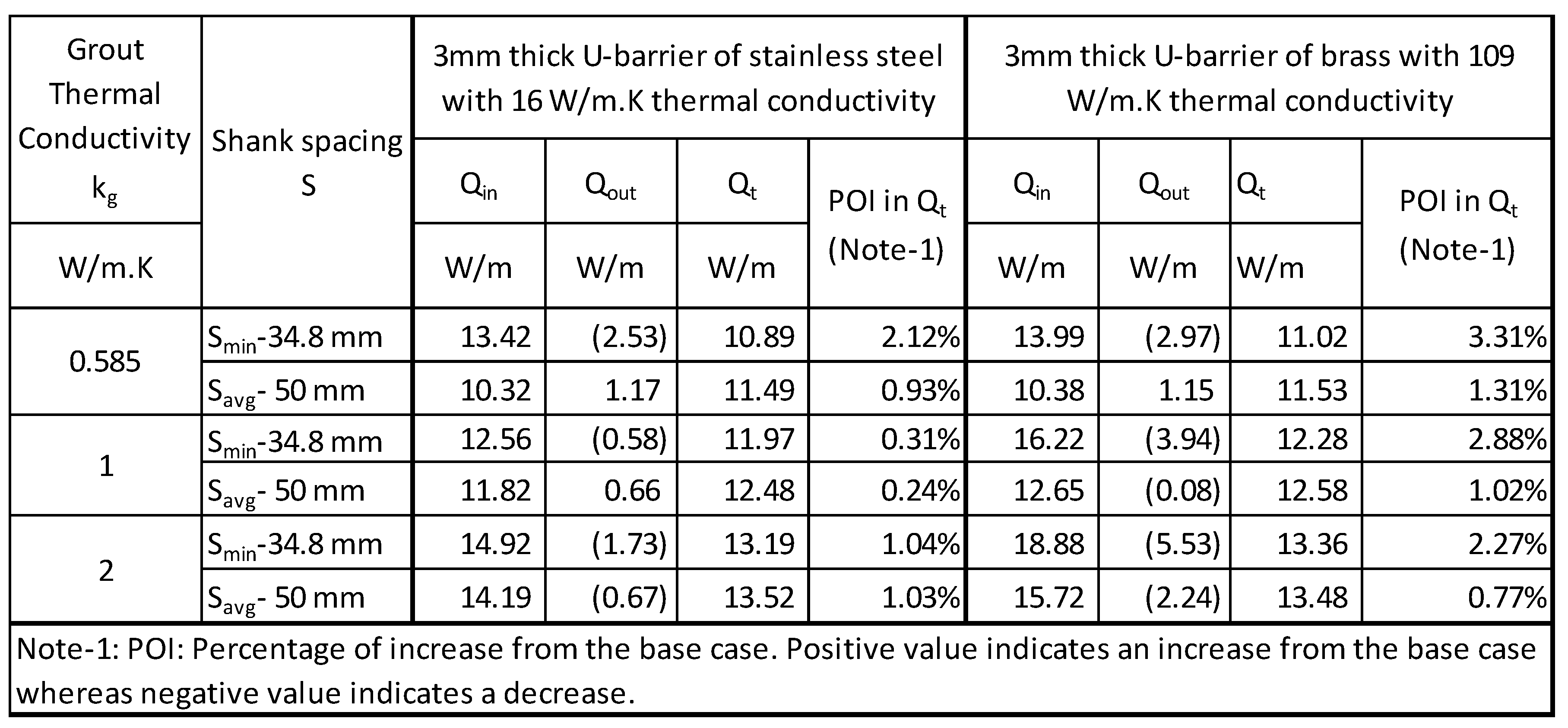
Table 17.
Length of BHX- Single U- barrier.
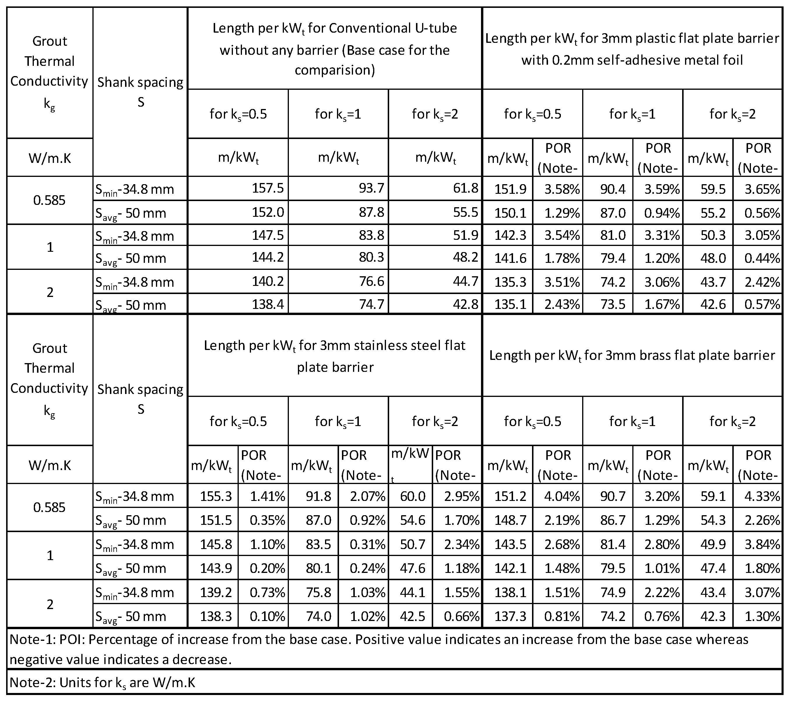
Table 18.
BHX heat transfer for 4mm double flat plate barrier at soil thermal conductivity of 1 W/m.K.
Table 18.
BHX heat transfer for 4mm double flat plate barrier at soil thermal conductivity of 1 W/m.K.
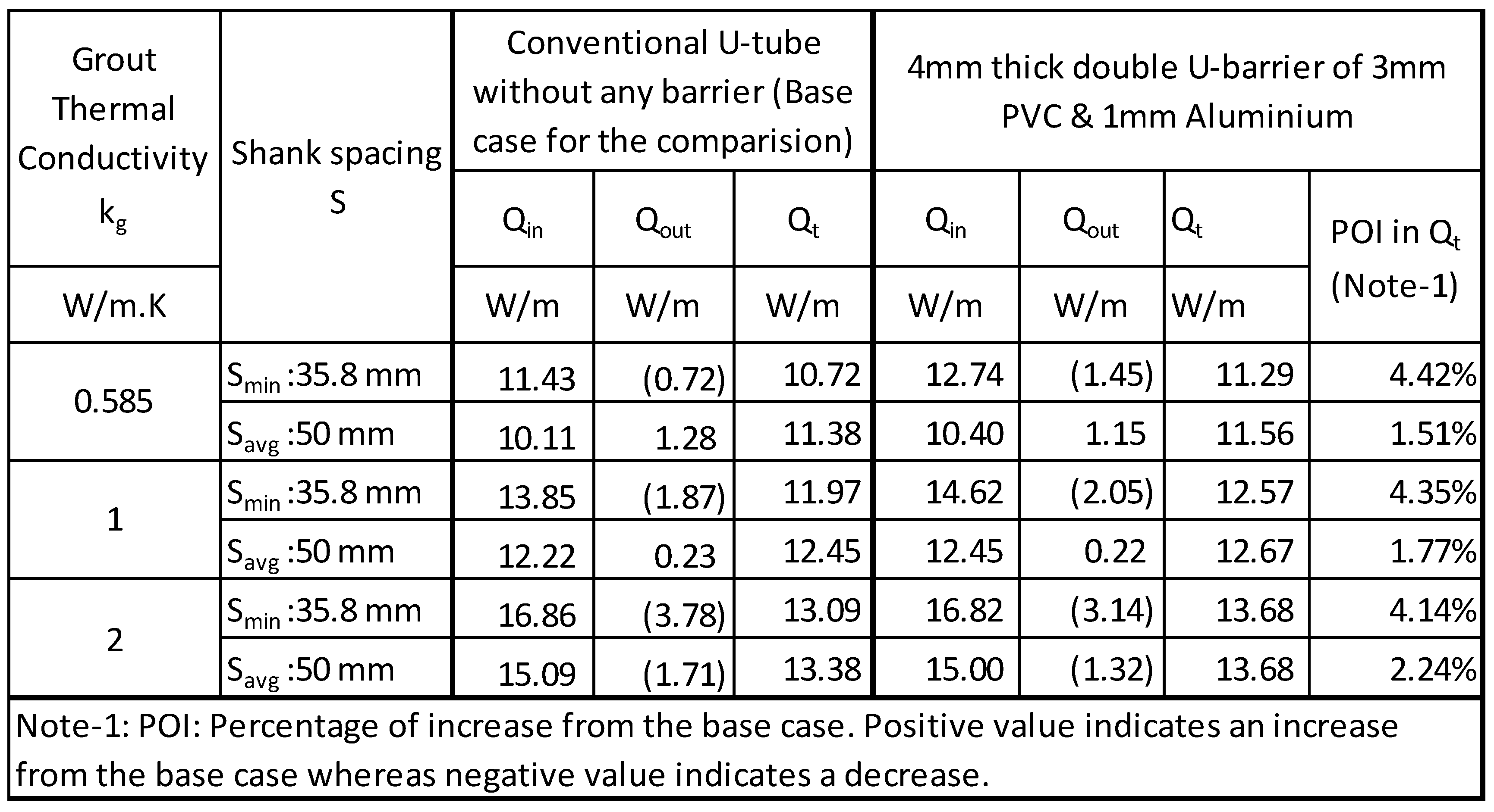
Table 19.
BHX heat transfer for 6mm double U- barrier at soil thermal conductivity of 1 W/m.K.
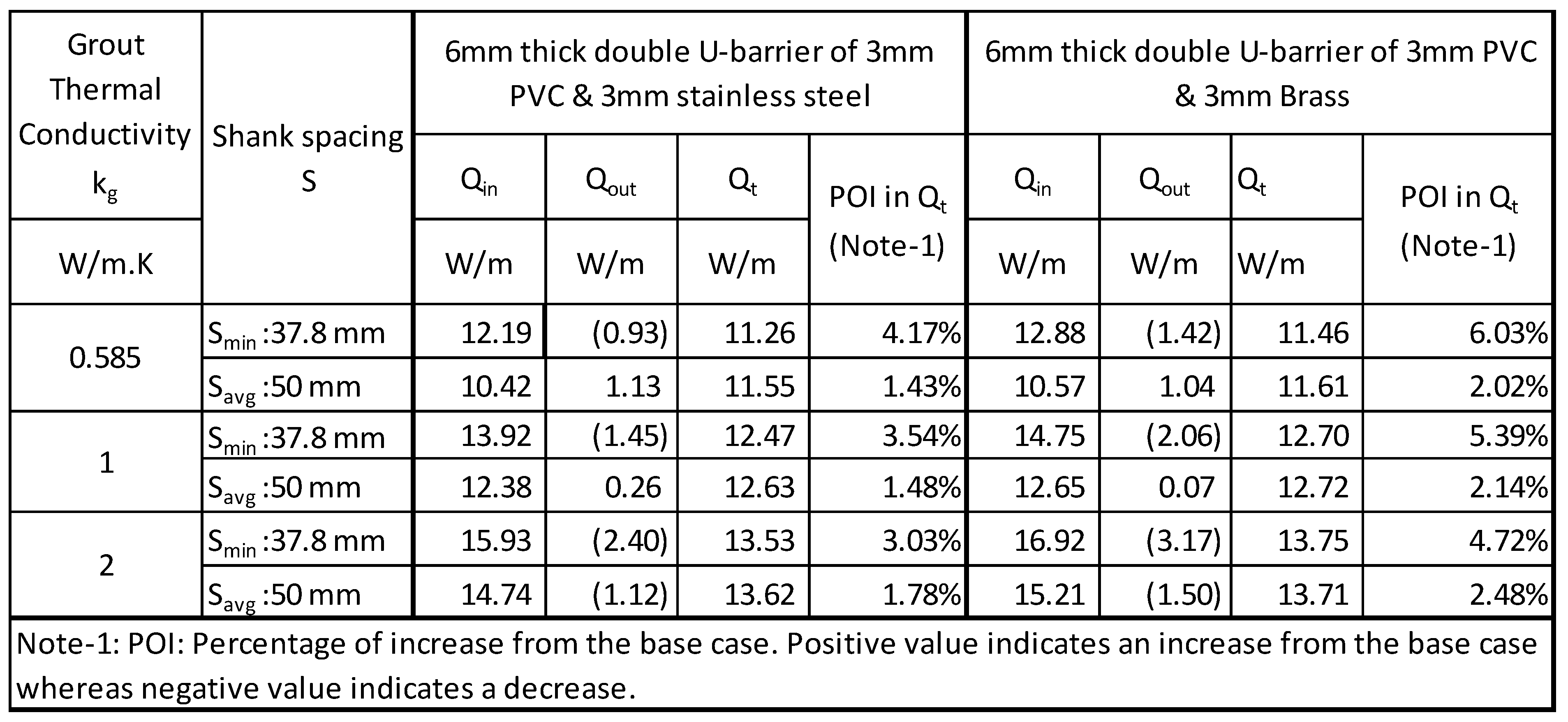
Table 20.
Length of BHX- 4mm double U-barrier (PVC & aluminium).
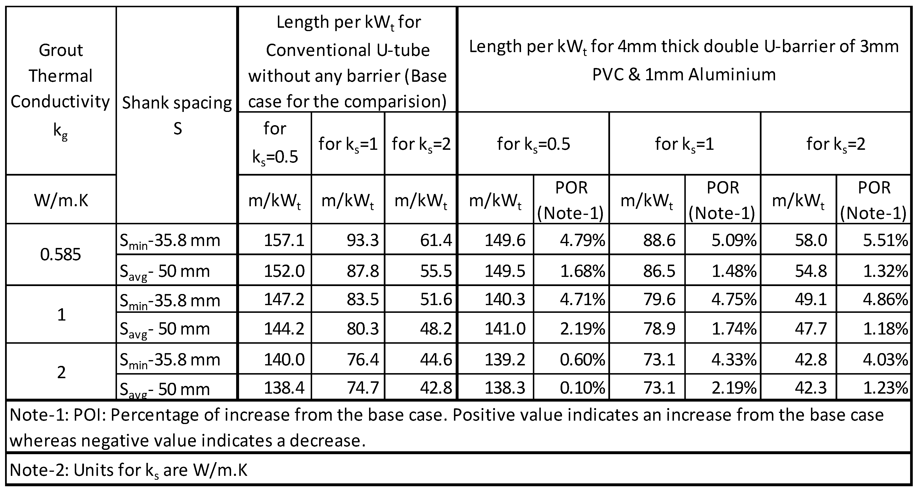
Table 21.
Length of BHX- 6mm double U- barrier (PVC &stainless steel and PVC & Brass).
Disclaimer/Publisher’s Note: The statements, opinions and data contained in all publications are solely those of the individual author(s) and contributor(s) and not of MDPI and/or the editor(s). MDPI and/or the editor(s) disclaim responsibility for any injury to people or property resulting from any ideas, methods, instructions or products referred to in the content. |
© 2024 by the authors. Licensee MDPI, Basel, Switzerland. This article is an open access article distributed under the terms and conditions of the Creative Commons Attribution (CC BY) license (http://creativecommons.org/licenses/by/4.0/).
Copyright: This open access article is published under a Creative Commons CC BY 4.0 license, which permit the free download, distribution, and reuse, provided that the author and preprint are cited in any reuse.


