
Submitted:
18 November 2024
Posted:
18 November 2024
You are already at the latest version
Abstract
We survey delay testing of digital circuits. The advanced semiconductor process technology results in high-speed circuits in which the presences of delay faults are highly possible. Delay faults affect the timing behavior of the circuit when operated at its designated speed of operation. To detect such delay defects and guarantee the timing correctness of the circuit delay testing plays an important role. In this paper, we review several delay testing techniques with emphasis of path delay fault testing. Many innovations have been introduced since 1990s, both in delay fault models and test generation techniques. A review of this paper highlighting important delay test methodologies of the recent past with the assumption of its greater importance in the future than it has now. We also applied the path delay fault testing method in hardware security. Experimental results on several benchmark circuits show that we can achieve 12.7%-19.6% variation in statistical path delay fault coverage in the infected integrated circuits.
Keywords:
Path delay fault testing
; test generation
; path selection
; hardware Trojans
; HT detection
; Hardware security
1. Introduction
As feature lengths of integrated transistors are decreasing, the amount of delay defects appearing in an IC is becoming a major concern while ensuring the timing correctness. This concern mandates appropriate tests to detect violations of the performance specifications of the circuit. Early approaches considered only logical correctness and assumed high stuck-at fault (SAF) coverage is sufficient to guarantee high-quality products. However, in order to increase the yield, industries have encouraged researchers to develop new test methods that can ensure timing correctness. Delay testing is considered as the best solution [1]. This area receives growing attention from both industries and academia. As a result, several delay fault models and numerous test methodologies have been proposed in the past two decades. This paper reviews a selection of existing delay test research results and encompasses basics with state-of-the-art techniques that address some of the current methodologies in delay testing.
Delay fault testing in digital circuits follows the steps of test generation, fault simulation, and fault grading. The creation of effective stimuli is an important part of the delay test procedure because it determines the fault coverage values [2]. Models bridge the gap between physical reality and mathematical abstraction, and therefore physical defects of digital circuits can be modeled as delay fault models when the defect affects the operating speed of the circuit. Test stimuli are then generated based on this delay fault model, which are used to verify the timing correctness of the circuit. The well-known delay fault models are the gate delay fault model, transition delay fault model, and path delay fault model. The gate delay fault model is delay-dependent because it makes assumptions about circuit delays. In this model, small-sized delay defects may not be detectable, and the analysis may be invalidated if certain assumptions on delays in the circuit do not hold [3]. The transition delay fault model and the path delay fault model, on the other hand, are delay-independent since they do not make any assumptions about circuit delays[4].
The transition delay fault model is similar to the gate delay fault model in which slow-to-rise (STR) and slow-to-fall (STF) faults are considered at gate inputs and outputs. The delay due to such slow transitions is assumed to be large enough to cause a delay fault when a signal propagates along any path through the fault site in the circuit. In the transition delay fault model, even though the test generation and fault simulation techniques are simple and require only minor modifications to stuck-at-fault (SAF) tools, it will not detect small delay defects (SDD) [5]. Chatterjee et al. [6] introduced a segment delay fault model to address the limitations of basic delay models. This model represents any general delay defect ranging from a spot defect to a distributed defect but restricts the length of segments and the number of segment faults that need to be considered.
However, the path delay fault model considers cumulative propagation delays along paths in a circuit to detect delay faults [7]. This model addresses the real situation of the circuit when there is a delay defect, and fault detection can be guaranteed by robust tests with no assumptions on circuit delays. Even though the path delay fault model supports an effective delay test method, it has several challenges in generating test patterns. These challenges include: (i) detecting small delay defects and shorter paths, (ii) pre-selection of longest paths in a circuit, and (iii) detection of faults that cannot support robust tests [8]. Path delay fault testing of large circuits remains an open problem, especially in achieving high fault coverage with cost-effective methods. These limitations have resulted in a lack of tools to cope with this type of testing and have prevented the adaptation of PDF testing. Motivated by this lack of tools, several recent research works have been engaged in developing techniques for PDF testing.
In this paper, we focus on surveying such selective test generation and fault simulation techniques based on the path delay fault model. Even though this study presents largely a qualitative view, we believe that this paper provides enlightening information on delay testing. A brief path delay fault (PDF) test primer in Section 2 provides background information. The path-selection techniques and test generation techniques are presented in Section 3 and Section 4, respectively, followed by a PDF testing on hardware security in Section 5 and conclusions in Section 6.
2. PDF Test Primer
Delay testing helps to ensure the hardware design in circuit level meets the desired performance specifications.
2.1. Delay Defect and Delay Test
The delay defect in a circuit is manifested only when the delay of the propagated signal through a path arrives after the specified cycle time. Delay defect size (δ) is directly proportional to the path length (PL) or the difference between the designed cycle time (td) and actual arrival time (ta) [9]. If the defect is only considered at a particular point, such as a gate output or a signal on a path, it is called a point-defect or lumped delay defect. This can be used to model bridges and opens in a circuit.
If the defect is considered distributed along a path, then it is called a distributed delay defect. In this case, the applied signal passes through multiple lines in a path, and the accumulation of delay for those signals may be significant enough to impact circuit speed. This cumulative effect is used to model defects due to process variations [10]. Path delay faults model physical defects in a circuit with a gate-level representation and consider cumulative propagation delays along paths. For example, too low doping in channels leads to higher resistance than specified, yielding increased delays on every transition. However, a path-delay fault test can also detect spot defects in cutting-edge sub-micron level along the path [11].
2.2. Fundamentals of PDF Test
The path delay fault test considers two faults associated with each path in a circuit. Each path begins at a primary input, contains a chain of gates, interconnects, and ends at a primary output. The first fault is related to a falling transition at the source of the path, and the second fault is related to a rising transition at the source of the path. If the signal transition along the path accumulates too much delay due to defects, the rising/falling transition on the output will arrive late. This indicates that the presence of defects has been detected by the applied test stimulus [12]. Two-pattern tests are required to detect delay faults in combinational circuits, while test sequences may be required to detect delay faults in sequential circuits.
Let us consider a two-pattern test P = (p1; p2), in which two consecutive test patterns with opposite values on some input pins are applied to the primary input of the circuit with a pre-determined time interval. The primary input (PI) leads to any path in a circuit and ends up at the primary output (PO). When p1 = 0 and p2 = 1, the test detects a slow-to-rise (STR) fault on the rising transition. In this case, p1 is first applied to PI, initiating the signal transition through the path. The applied logic-low (p1 = 0) signal arrives at PO after the specified delay time (ts) of the circuit and ensures the fault-free arrival of p1 as shown in Figure 1(a). Now the second pattern, logic-high (p2 = 1) signal, is applied to PI, and the output response at PO is observed after ts. If there is any defect in the path, then the actual arrival time (ta) of p2 will exceed td, as shown in Figure 1(b). The time difference between ts and ta gives the delay size. This test detects the slow-to-rise (STR) fault of the path. Similarly, when p1 = 1 and p2 = 0, the test detects a slow-to-fall (STF) fault on the falling transition, as shown in Figure 1 [13,14].
The following procedure summarizes the two-pattern PDF test method:
- Apply the first pattern (p1), which launches an initial transition and establishes the initial state of the circuit;
- Apply the second pattern (p2) after a time interval, launching the second transition in a path and propagating the signal value toward the output;
- Capture the response at the primary output after a pre-determined time interval. If there is a delay defect, an incorrect response will be captured;
This same test procedure can also be applied to sequential circuits with flip-flops at PIs and POs, as shown in Figure 2. In this typical delay test architecture, as indicated in [15], input and output latches are part of the circuit or are provided by the automatic test equipment (ATE) for testing. During test mode, the input and output latches are controlled by two different clocks: the input and output clocks. These independent clocks allow a phase delay to apply the two consecutive test patterns. As mentioned earlier, a two-pattern test assumes that all signals due to p1 have reached a steady state before applying p2. If the steady-state assumption is not true, transient signals may be present in the circuit, which could interfere with the testing of the targeted path [16]. To avoid this problem, test patterns (p1, p2) are applied at slower than the rated clock frequency. As indicated in the timing diagram of Figure 2, p1 is applied at t0, and p2 is applied at t1 of the input clock of the input latch. The time difference (t1 - t0) allows all signals in the circuit to stabilize under p1. Then, the output clock is latched by the time period, which is equal to the rated clock period. This allows the circuit to settle down with signal transitions due to p1 followed by p2. If the delay of the selected path is longer than the rated-clock period, then the faulty output will be observed in the output latch [17].
2.3. Faults Detection in a Gate-Level Circuit
The goal of test generation based on the path delay fault model is to derive test patterns that can be used to test each manufactured circuit/component for timing correctness. Qin et al. [18] analyzed the major reasons for low path delay fault coverage in digital circuits. To achieve higher confidence in path delay fault tests, the number of untested faults in a circuit should be small. In practice, achieving high fault coverage is challenging mainly due to non-activatable paths, and it is difficult to produce two consecutive states effectively to create and propagate a transition through the paths [19]. Based on signal propagation criteria, fault detection under PDF test offers two different test methods: robust and non-robust tests. This subsection provides the basic principle of these two tests, and detailed descriptions can be found in [20,21].
In robust testing, fault detection can be guaranteed with no assumptions about circuit delays. However, it requires stringent logic conditions for the detection of a delay fault. For instance, in robust testing, off-path inputs of logic gates along the targeted path are expected to have stable non-controlling values (NCV) while propagating either a falling or rising transition through on-path inputs, as shown in Figure 3(a). When the test pattern pair activates signal transitions on the targeted path, all off-path inputs of the gates along the path should be robust. This is called a robust sensitizable path, which results in a high-quality test. However, most of the circuit paths cannot be tested under robust conditions, leading to robust untestable path delay faults [22]. In non-robust testing, fault detection requires knowledge about delays in the circuit, even though it is less stringent than robust testing. For example, if there is an NCV → CV (control value) transition in the on-path input of the gate along the targeted path concerning the applied test patterns, then a CV → NCV transition is expected in off-path inputs of the same gate, as shown in Figure 3(b). The transition arrival time on off-path inputs should be earlier than the transition arrival time on on-path inputs to detect faults in the targeted path. If the off-path signal transition arrives after the on-path signal transition, the fault cannot be propagated to the output, resulting in an invalidated non-robust test [23].
3. Path Selection of PDF Testing
The number of testable paths can be huge in the CUT. It is impractical to consider all circuit paths because this would cause the size of the data structure inside the test patterns generation (TPG) tool to blow up. In order to keep the whole path store inside computer memory, the size of the path store with respect to the number of paths was set to a reasonable value. Generally, path selection approaches are based on either selecting paths with high fault probability, i.e., K-longest path selection, or improving the quality of a path set of a specific size with the assumption of structural or spatial correlation and statistical timing analysis, i.e., time defects cause many paths to be faulty that pass through the defective site. However, a simple and effective approach is testing the longest paths through a fault site because it increases the fault detection probability.
Studies such as [26,27,28,29] have analyzed the method of finding the longest paths through each gate or line in a circuit. Other studies [30,31,32] have described the fault propagation under certain sensitization criteria and finding the global longest paths. Many ATPGs, like NEST [33], DYNAMIT [34], RESIST [35], VIPER [36], and KLPG [37], have extensively studied the problem of finding k-longest testable paths through each gate in a circuit. Additional studies [38] have discussed the recursive path selection method, which does not require the iteration process for each path and correlation between paths. It recursively continues and selects a requested number of paths simultaneously. The branch-and-bound algorithm-based statistical path tracing was introduced in [39] and reports the statistically most critical paths from industrial circuits with multi-million gates. However, this section gives an overview of well-known path selection methods and reviews a few selective methods.
3.1. Path Selection: Term Analysis
Generally, in gate-level circuits, timing analysis often relies on gate delays, interconnects, and signal propagation where the earliest, latest, and average signal arrival times are estimated for each PI to PO pin pairs [40]. Based on these discrete timing values, the delay of a path can be defined as the accumulated delay on the path. Then, the set of critical paths can be constructed by selecting either a fixed number of the longest paths or all paths that fall into a pre-defined time range [41,42]. Eventually, this set of longest paths is expected to ensure a complete topological coverage of the circuit. However, this basic definition for the path selection procedure may not be sufficient to model delay defects in deep sub-micron technologies [43]. In deep submicron technologies, delay variations due to the manufacturing process, small defects, and/or signal noise cannot be detected with discrete timing assumptions and accumulated delay effects of longest paths. Even though there is no universal procedure defined for path selection in circuits, some techniques, like k-longest path selection, recursive path selection, and statistical path selection methods, are generally used in PDF testing.
The commonly adopted method in both academia and industries is to select the K-longest testable paths in a circuit. In this method, the fault list is often set equal to the K-longest testable paths. This K value depends on the reasonable number of test patterns [44,45,46]. Also, the selection of the longest or critical path depends on the timing length of a path or all testable path-delay faults considered to be longer than a predefined limit. It is often calculated using discrete delay models based upon worst-case timing scenarios. This K-longest path selection approach guides the test generation process along the longest paths with minimum slack. For instance, the difference between the minimum of the required time and the maximum of the arrival time at any given node is the slack. This simple and effective process selects long paths and obtains the difference between the arrival and required times by propagating fault effects along the longest paths. Even though the path selection technique is closely followed by the test generation, the next subsection only discusses the path selection for our simplification.
3.2. An Overview of Path Selection in ATPGs
An ATPG tool, NEST [33,47], generates paths in a non-enumerative way. This tool can handle a large number of paths and detect large numbers of path delay faults by propagating transitions robustly through parts of the circuit. It does not require enumerating the specific paths through every selected subcircuit where the transitions are propagated. This tool uses labeling techniques that consider only lines in selected subcircuits and is used to determine test generation objectives effectively [48]. However, NEST is only effective in highly testable circuits where a large number of path delay faults are testable. This method removes the most limiting restriction of the path delay fault model while handling a large number of path delay faults.
In contrast to NEST, the Delay Fault Oriented Automatic Test Pattern Generation System (DYNAMITE) [34] introduced an effective method to handle poorly testable circuits. The path sensitization procedure of this tool is used to identify large numbers of path delay faults as redundant by a single ATPG attempt. If the selected subset of paths is not well testable due to the presence of many redundant paths, this method allows dynamic switching to another subset of paths [49]. This will eventually succeed in generating a test set for all testable path delay faults and identifying all redundant ones. However, in highly testable circuits, many faults are treated separately, which results in huge memory consumption. It shows that this method is not suitable for larger circuits.
Recursive selection and sensitization technique (RESIST) [35] overcomes the limitations of NEST and DYNAMITE. RESIST shows a cost effective method for a path selection and to test a large number of path delay faults in both highly testable and poorly testable circuits [50]. It introduces an optimal search strategy for paths selection. For instance, many paths in a circuit have common subpaths which results dependent path delay faults. It is enough if these paths are sensitized only once [51]. This tool addresses this issue by reducing the number of value assignments during path sensitization. To illustrate the basic idea of RESIST, let us use Figure 4, which is from [35]. In Figure 4, a structural path (P) starts at a PI or present state lines (PS) and ends at a PO or next state lines (NS). P consists of several structural subpaths (S0, S1 … Sn). Each subpath leads from a PI/PS or a fanout stem to a PO/NS or a fanout stem.
To simplify the following discussion, we will assume that P is associated with two different faults. They are and (rising and falling transitions at S0. The transitions at all other on-path signals , by uniquely determined by gates along path P. Here only the bold paths starting from y0 (PI) and ending at yn (PO) will be considered. In which, there are 2n different subpaths where and , between consecutive fanout stems. Each path from y0 to yn consists of n subpaths . Altogether there are 2n different paths from y0 to yn.
Conventional ATPGs sensitizes each path separately. Hence, it performs subpath sensitization steps (SPS) in any given circuit Cn. To reduce the number of SPS, RESIST uses a different strategy.
Let us consider the sub-paths and from yo to fanout stem y1. Both subpaths are included in 2"-l paths from yo to yn. Hence, sensitizing and only once reduces the number of SPS from S(n) to,
where S(n-1) := (n-1). 2n-1 is the number of SPS performed by conventional ATPG in circuit Cn-l. Applying the same principle at all subcricuits (Cn-1, Cn-2 … Cn), the number of SPS becomes
Since S(1) = 2, compared with conventional ATPG, the number of SPS is reduced by,
For instance, if n=60 then the reduction factor is 30. The reduction factor increases with an increasing number of fanout branches (fanout > 2) converging to n. This simple sensitization procedure gives a speedup factor of this method that grows linearly with the circuit depth. Performing the sensitization step for a common subpath S only once requires that the TPG status is updated at fanout stems. Both mandatory value assignments for subpath sensitization and the corresponding unjustified lines have to be stored in order to exploit the TPG status for all paths including subpaths. Also RESIST identifies large sets of untestable paths without enumeration.
[52] extends the RESIST technique and introduced an efficient method to solve the problem of finding a set of longest testable paths through different gates under unit delay assumption. This ATPG technique automatically determines the longest testable path passing through a gate or wire in the circuit without first listing all long paths passing through it. The path selection is based on a graph traversal algorithm that can traverse all paths of a given length in a weighted directed acyclic graph (DAG). This method modified the algorithm presented in [53] and used powerful search space pruning techniques while searching for the longest testable path through each node [54]. Since this improved version of RESIST assumes a unit delay model, there is no obvious way to extend it to handle the problem of finding the K longest testable paths through each gate. For instance, this method fails when applied to C6288.
[24] introduced a timing analysis tool based on the recursive learning technique. Recursive learning [25,55] is a technique that can identify all necessary assignments required to satisfy a set of value assignments in a circuit. Necessary assignments are computed by temporarily injecting all combinations of possible values to the gate inputs that would justify the gates and observing the result after direct implication using a novel recursive ATPG technique [56]. This timing analysis tool is used to find indirect conflicts during path building with the forward trimming technique. It efficiently identifies the global longest paths in combinational circuits, and prevents the checking of multiple paths with equivalent constraints. Instead of generating many long structural paths and checking their testability, this tool grows paths from PIs, as shown in Figure 5.
3.3. Paths Selection/Generation Procedure
Step 1: First, during the preprocessing, the circuit netlist is loaded and represented as a graph with n primary inputs and m primary outputs. All circuit components (i.e., logic gates), PIs, and POs are represented as nodes in the graph with edges representing circuit interconnect. Some delay information such as Omax, Imin, and Imax about each gate need to be determined and loaded at this time [57]. First, the maximum distance from each gate to a PO is calculated at each node in the circuit. It is represented as Omax(G). The maximum Omax(G) of all PIs is the delay of the longest structural path in the circuit. This can be calculated through a simple depth-first search. Imin and Imax represent the earliest and last possible time of signal transitions at gate G. These values are calculated assuming that all PI transitions will occur at time zero. But it is possible to relax this condition in order to allow input transitions to occur over a range, helping to reduce constraints applied to the circuit during path building.
Step 2: The path store contains the partial paths. A partial path starts from PI but has not reached PO. The partial path can be extended by adding one gate along its path. When this extension reaches PO, it becomes a complete path. To compute the longest paths during the path generation process, the partial paths are sorted by max Esperance [105]. It is calculated from the delay of the current gate and the largest potential delay to a PO.
Step 3: The path generation process begins by checking the path store for the largest partial path. The paths can be generated in decreasing order of path length based on the determined information. During the path generation process, after selecting a partial path, it is extended through the fanout with the highest esperance.
Step 4: The partial path extension begins by adding a new gate and applying the constraints to that gate. In VIPER [61], logic values are assigned to one or more PIs to satisfy the constraints on the newly added gate. However, this timing analysis tool uses direct implications, which are more efficient in finding local conflicts. It is used to discover blocked paths early.
Step 5:
If there is any conflict then the existing search with series of gates get trimmed off. This is called implicit false path elimination which guides the search toward the true longest path. It improves the search process during the path building phase of the incremental path generation routine. After direct implications if the path extension reaches PO without conflict then it is important to perform the final step, called path justification. The reason is that the immediate prior process such as direct implications of the path generation can only implicitly eliminate false paths with local conflicts. But still there is a possibility to have indirect conflicts which may cause a generated path to be false. This path justification is also used to determine a set of primary input values that can be used to sensitize the path. A FAN style decision tree based justification routine is used to sensitize the generated potential path. This process begins by applying all the constraints necessary to propagate a transition along the path. If the generated path passes the justification, then the path generator will go to another path [59]. This method can handle C6288.
Based on the idea of the path generation procedure described in the timing analysis tool [78], Qiu introduced K-longest path generation (KLPG) tool for both combinational circuits [79] and sequential circuits [80]. To avoid the repeated work during the path extension, Qiu have focused on particular gates one by one. In order to reduce the search space, Qiu also used the extended concept of [81] while relating long paths through different gates.
3.4. Observations
Section 3 shows an overview of some important path selection algorithms. Many path delay faults do not have robust tests, and therefore, it is necessary to develop efficient test generation procedures for non-robust tests. While propagating signal transitions through the path non-robustly, the worst-case delay may occur. It is also observed from the timing analysis that the delay of a path under non-robust test is longer than the delay of a path under robust test [60,61]. This can cause a delay defect affecting the path and may not cause the circuit to fail at its designated speed of operation under a robust test. However, the circuit will fail under a non-robust test or may fail the same test (t) in the presence of the same fault (f1) if the path operates under its worst-case delay. Developing test generation procedures for path delay fault testing is a challenging task.
4. Test Generation for PDF Testing – Non-Scan Technique
The problem of finding the longest path through each gate or line in a circuit has been extensively studied in [62]. Several recent works inherit the framework of the existing techniques for the path selection and have developed different test generation procedures with improved experimental results [63,64]. This section summarizes some existing test generation procedures with analysis.
Generally, PDF tests for digital circuits (combinational and sequential circuits) are based on either non-scan methods or scan methods. These methods are implemented in circuits using self-test techniques because self-test offers the ability to apply the stimuli effectively and analyze at-speed test signals with better accuracy. Built-in Self-Test (BIST) techniques are well-suited in the path delay fault (PDF) testing of digital circuits. This is a most preferable technique for detecting a very large class of physical failures in the circuits [65]. There are different ways to implement BIST, but it usually comprises the following blocks: a test pattern generator (TPG), a circuit under test (CUT), a response analyzer, and a BIST controller [66]. This section focuses on different automatic test pattern generation (ATPG) techniques for PDF testing.
4.1. Non-Scan Based PDF Test Setup
In this subsection, we describe the pseudo random test stimuli generation for PDF testing under the framework of [82,83,84]. Figure 6 shows the non-scan based BIST setup for PDF test. It comprises of netlist generator, path & test stimuli generator, PDF simulator and test controller with fault grading. The netlist generation is important in PDF test because netlist representation of the CUT simplifies the simulation algorithms and their implementation. It means that having an efficient netlist architecture is significant to achieve a better performance from the simulator. The netlist typically contains logic gates and their associated interconnects along with attributes for the gates. The structure of the netlist can be represented using a Directed Acyclic Graph (DAG) with two event-list classes. The fan-outs associated with each gate are in one DAG and the fan-ins associated with each gate are in another. This helps to perform forward and backward propagation through the circuit easily.
Second, the main cause of concern in PDF testing is the path generation. Section III reviews different path selection procedures in order to generate the longest testable paths. However, a K-longest path selection approach guides the test generation process along the longest paths with minimum slack. This approach selects long paths, and obtains the difference between the arrivals and required times by propagating fault effects along the longest paths.
Next important part of the test setup is the test stimuli generator. Test stimuli generator of [82] is based on accumulator and mersenne twister methods. Both accumulator based and mersenne based pseudo random test stimuli generators are using different weighting schemes which are explained in the next subsection. In each weighting scheme, first weights are generated. Those are then used together with the pseudo random generators. The generated weights are based on the single stuck-at fault model and a deterministic test set. It is also important to create the basis patterns based on stuck-at faults. It can help in the path delay fault testing if the weight-based test patterns for stuck-at faults would yield a better fault coverage result or not. In the basis patterns, each bit is shifted once from 0 to 1 and once from 1 to 0. Therefore, testing a path delay fault over with a subsequence of successors and intrinsic complement operations on each path effectively tests for both rising and falling transitions on its inputs. In this way, every basic pattern produces 2N test vectors, and N is the number of inputs to the circuit. Figure 7 shows the basic concept of SIC stimuli generator which produces SIC stimuli by first establishing a basis pattern. Then each bit is toggled twice in order to generate both rising and falling transitions. The test patterns are encoded using smith’s alphabet [88] as shown in Table 1. The concept of different test stimuli generation techniques and summary of different test stimuli generators are presented in the next subsections.
Third, the PDF simulator starts to evaluate the generated test stimuli by applying them into the generated paths. In which, the generated paths are translated into the PDF simulator’s input fault list format. This basically involves mapping the paths and its corresponding gates with levelized information. Then the test vectors need to be applied into the simulator. Thus, the PDF simulator computes the correct simulation value of all gates along the paths from the circuit netlist using the generated test vectors. During simulation, the correct signal value of each gate is computed one at a time in topologically sorted order. The levelization assures that the signal value of a gate is not computed before the signal values of the gates driving the inputs. All gates in the netlist are visited at least once. When a new test vector is applied during simulation, it can cause one or more signal changes at the inputs of the circuit.
Fourth, The PDF test controller manages the process of fault simulation, applying test stimuli and fault grading. According to the fault grading algorithm, it assigns a unique number to each path-delay fault and when a fault is detected the corresponding number is stored in a list. The enumerative algorithm [50] is intractable by definition since the number of path-delay faults is counted one by one. If the number of path-delay faults is very high then it is better to use a non-enumerative algorithm even though it is more complex [85,86]. It is fast and efficient while managing the huge number of longest paths and its corresponding faults. However, the fault grading requires a well-organized datastructure which can handle previously as well as currently detected faults efficiently for each test stimuli applied to the CUT.
4.2. PDF Test Stimuli Generation Techniques
This subsection describes a set of methods and techniques that can be used to design the test stimuli generators.
4.2.1. Pseudo Exhaustive Technique
Pseudo exhaustive test can give high fault coverage but applying test vectors, in the case of stuck-at faults, is only feasible for circuits with few inputs n. However, sometimes, it is possible to partition the circuit so that each sub circuit can be tested exhaustively. Pseudo exhaustive test generators may be realized in many ways. Two interesting pseudo-exhaustive generators based on accumulators were presented by Rajski and Tyszer in [4] as a part of the ABIST methodology. These two generators are given here.
- ACC-FIXED: Optimal accumulator-based generators for single size subspaces: Arithmetic Built-In Self-Test (ABIST) [87] is a term introduced by Rajski and Tyszer. They pointed out the existing components in today’s complex integrated circuits often contain ALUs and memory that can be reused for testing purposes. One efficient way to generate stimuli (measured in the number of clock cycles needed to generate a new vector) is to accumulate a constant as shown in the below equation.
There are ways of choosing pairs of C and I, and the resulting generator exhibits some interesting properties for each pair. By carefully selecting the parameters C and I, it is possible to cover exhaustively every subinterval of size r within the first 2r test vectors. A pseudo exhaustive generator can be used to test modules with physically adjacent input lines (e. g. adders). The value of r should then be set equal to number of inputs to the partition with the largest number of inputs;
- ACC-RANGE: The best accumulator-based generators for subspaces within a range of sizes. The number of inputs to the partitions often varies, and in such cases a generator made for subspaces with fixed size might be suboptimal. However, It is not possible to synthesize values for C and I for equation 1 in such cases.
4.2.2. Pseudo-Random Technique
The cost-effective BIST techniques are basically using pseudo-random patterns. Pseudo random pattern generators are used to generate test sequences that have the same properties as true random sequences even though the sequence is generated by a deterministic algorithm. The number of test vectors needed in order to detect all faults are usually much smaller than the number of test vectors generated during an exhaustive or pseudo-exhaustive test. However, the test sequence might still be long due to random pattern resistant faults.
- TWISTER - Mersenne twister pseudo random generator: Mersenne Twister [74] is a pseudo-random generator which has a period of 219937 − 1. The generator is fairly complex and is not suitable for use in built-in self-test. However, there are many pitfalls when designing pseudo-random generators, and the Mersenne twister may thus be used as a verification tool in the design phase. If, for instance, an LFSR based generator in a BIST environment performs much poorer than the Mersenne twister, it may be caused by some structural or linear dependencies.
- MAC - Multiply and accumulate based generator: In order to reduce the test application time of large sequential circuits with scan, the scan chain is usually broken down into several scan chains. These scan chains must then be fed by the test generator. LFSRs may, due to structural and linear dependencies, fail to produce some test patterns. Instead one can use a generator based on multiply and accumulate (MAC) operations.
Even though pseudo-random BIST provides an cost-effective solution, it has few drawbacks such as low fault coverage and high power dissipation. Random pattern resistant (r.p.r.) faults result in low fault coverage during testing. To address this issue, test points need to be inserted in the circuit that needs to be tested or improve the test pattern generation logic. Both can help to increase r.p.r fault detection probability. However, pseudo-random patterns correspond to high switching activity in the circuit that creates another challenge of high-power dissipation. Thus, overheating occurs but the integrated circuit designed to handle only low power dissipation from the functional operation. Though, this issue in pseudo-random BIST has been explored by different studies, the better options is about adding weight logic to the patterns and targeting to detect r.p.r faults and achieving low power dissipation during testing.
4.3. Weight Technique
Here, the methods for generating weights based on structural analysis of the CUT.
4.3.1. Deterministic Test Set Based Weight Computation (DTW)
There are several ways of creating weights for a weighted stimuli generator. One common method used in conjunction with the single stuck-at fault model, is to create weights based on a deterministic test set for stuck-at faults. It is interesting to find out whether or not a weight set based on a deterministic test set for stuck-at faults would yield a good result. For instance, first a deterministic test set for the circuit under test can be created using TetraMax, an ATPG from Synopsys. This deterministic test set will contain number of test vectors as shown in Figure 8.
Then the weights can be determined by first counting the number of test vectors n1i with the symbols ’1’ and ’X’ present at input i, as well as the number of test vectors n0i with the symbols ’0’ and ’X’ present at input i. Values for n0 and n1 is shown in Figure 9 for the test set in Figure 8. The probability for observing ’1’ at the input of the circuit under test at input i can be computed using p1 = n1/(n1 + n0). [82] showed the ATPG can be used in order to extract the K-longest testable paths in a circuit together with a valid test vector. The weights were then computed based on the deterministic test set for path delay faults. This weights based deterministic test generators are proved their efficiency in detecting pat delay faults (PDF-DTW).
4.3.2. Counting Based Weight Computation (CBW)
Fault coverage measurements helps in generating weights. If we consider the CUT is attached with the pseudo random generator (PRG), the PRG can provide uniformly distributed basis patterns to the inputs of the circuit. Counters associated with each input pin can be used to store the number of faults detected for each applied pattern. When the desired number of basis patterns has been applied then the weighting logic can be computed using counter values associated with each input pin. Generally, circuits will have some paths that are easy to detect while other paths that are more difficult to detect. It is better to tune the weights that can target on to the faults that are more difficult to detect. When weights were generated using this method, a huge number of SIC patterns needed to be applied and computing weights.
4.3.3. Fault Subset Based Weight Computation (FSW)
Each signal propagation uses the input-node as a start point and ends at an output-node. To cover the complete path, the set of all path-delay faults needs to be divided into smaller disjoint subsets. It can contain only faults that ends at a particular output, and also can start from particular input. Instead of trying to detect all faults in the fault set using one fixed weight set, it may be more efficient to restart the generator with weights that target one subset of the fault set at a time. The CBW technique can easily be adapted with this technique.
Figure 10 shows a circuit with two inputs and four outputs. Assume that the uniformly distributed base patterns from a pseudo random generator has been applied to the circuit. There are two arrays of counters associated with each input. One array of counters (S0ctr, S1ctr) for each of the two possible input values (S0, S1). The counters (S0ctr [i], S1ctr [i]) are used to store the number of faults detected that ends at output i when the input has the value either S0 or S1. When the desired number of base patterns have been applied, the weighting factors can be computed for every input and subset i by using the equation, p1[i] = S1ctr [i]) / (S1ctr [i] + S0ctr [i]). These computed weights are used to bias a pseudo random generator. In order to restart the stimuli generator with new weights, either relative fault detection (REL) based or simulation (SIM) based weight sequence optimization technique can be used.
4.4. Implementation of PDF Test Stimuli Generators
Based on the above-mentioned techniques, [82] introduced 14 different types of test stimuli generators. These ATPGs are intended to use in software based BISTs. The stimuli generators are based on accumulator and Mersenne twister based pseudo random generators. For instance, we describe here about the implementation of accumulator based pseudo random test stimuli generator (A-PRG) using assembly code. The fault simulation of this two-pattern test is assumed that the first pattern is held until it has propagated through the CUT. The second vector creates a transition and the signature compactor must sample the response one clock cycle later in order to capture any path delay faults. The test generators were realized in test program programs and test programs were implemented using the instruction set given in Table 2. It is assumed that every instruction executes within one clock cycle. Test generators can easily be extended in order to include a response compactor as well. The test application was assumed that the CUT is connected to the processor through the register R0, and that R0 has the same width as the number of inputs to the CUT.
The implementation of the accumulator based pseudo random test stimuli generator (A-PRG) using assembly code is shown in Figure 11 (a). The program starts at the address with the label INIT where the test program generator is initialized. Rising and falling transitions are then created for each bit as shown from the address with label SIC. When all 2n transitions have been created, a new basis vector is created until a total of N basis vectors have been created. The N basis vectors corresponds to 2n*N two pattern tests. The output of register R0 is assumed connected directly to the CUT, and the sequence generated by the test program is shown in Figure 11 (b). The vertical wave in the Figure 11 illustrates the falling and rising transition on the LSB in the input vector.
This section discussed a review of several non-scan-based test stimuli generation techniques for PDF testing. The next sub-section gives the application path delay testing technique in hardware Trojans detection.
5. PDF Testing in Hardware Security
Hardware Trojans (HTs) have become a significant concern in the trustworthiness of integrated circuits (ICs). If an untrusted foundry fabricates the IC, there is potential for an adversary to insert malicious behavior, known as Hardware Trojans (HTs). Detecting HTs is very challenging because of the diversity of Trojans and the stealthy modifications made to the hardware. HTs can be intelligently inserted in such a way that there is no impact on the function, area, power, and performance of the original design [67]. They can also be inserted in a way that passes typical testing procedures [68], and they can be activated at any instant during runtime. Adversaries typically target weak sites, such as paths with large slack or paths with low switching activities, when inserting HTs [69]. This section discusses detecting such HTs using the path delay fault testing approach. Our method focuses on detecting HTs by comparing the statistical path delay fault coverage (PDF Coverage) values before and after HT insertions for the particular selected paths and test seeds [70].
5.1. HT Detection Principle
The HT detection steps are as follows: i. First, select K shortest paths, ii. Generate m test patterns based on particular seeds, and compute the PDF coverage values, iii. Second, identify paths with large slack values among the selected K shortest paths, and insert an HT into the identified paths, iv. Generate the same m test patterns based on the same seeds, and compute the PDF coverage value for each circuit. This value will differ from the previous one because these patterns are not targeted to excite the inserted HTs, and the added interconnects and gates from HTs will affect the PDF coverage values. To observe the HT payload for each of these paths, an appropriate vector must be generated to excite the path. This requires a different set of test generation conditions from typical path delay fault testing.
In practice, PDF coverage values of HT-free ICs can be obtained by applying test patterns and performing PDF coverage measurement. After applying the patterns, a limited number of ICs are reverse engineered to ensure they are HT-free [71]. Once the reference PDF coverage values are obtained, the same patterns are applied to the rest of the ICs. If the PDF coverage values differ from the reference values, the corresponding ICs are considered suspicious, potentially containing HTs. Different-sized HTs under varying process conditions can be detected by applying test patterns and observing the PDF coverage values [72].
The fault simulation algorithm together with fault grading technique and its test patterns generation are based on three-level (3-L) software platform [83,84] that we have introduced earlier, and [73]. It works with a logic of SIC based test pattern generation technique in detecting K-shortest PDFs rather than K-longest PDFs. The SIC patterns are pairs of patterns and differs in only one bit. The pattern generator varies depending on how the seed patterns are generated. In our previous works, different methods for generating seed patterns were explored, including general arithmetic (GA) and the general Mersenne Twister (GT) test generators. It used the logic of pseudo-exhaustive and weighted random generation techniques [74,75].
The generated weights are associated with the single stuck-at fault model and based on a deterministic test set for stuck-at faults. Even though the test patterns are used to detect path delay faults, creating the seed patterns based on stuck-at faults is a sensible approach. It is also meaningful to test whether weight-based test patterns for stuck-at faults yield good coverage for path delay faults. The enumerative implementation and skip-list-based data structure were used to compute path delay fault coverage values [76]. The skip-list data structure contains multiple pointers since elements can be in more than one list. This implementation makes the software easier to manage, and the open-source code for the skip list is particularly useful [77]. When a path delay fault is detected, a search in the skip-list is performed to find the proper position to store the fault. If the position is empty, the new path delay fault is stored; otherwise, the fault has already been detected.
5.2. Experimental Results
Our experiments considered 10K-shortest paths of ISCAS’85 benchmark circuits. 10 million (10M) single input change (SIC) test patterns were applied and the same was repeated ten times under the consideration of statistical variations. The number of test vectors are high enough to achieve high path delay fault coverage. Results are shown in Table 3. Each path is examined by SIC test vectors (rising/falling transitions) and detected faults associated with are logged.
In case 1, the generated test vectors applied to the CUT. For each detected fault, the simulator logs the path number in which the fault got detected. It makes it easier to account the detected faults and drop its corresponding paths from the path list, immediately. This helps in the realistic testing, and not repeating the test again on the already tested paths. The number of detected faults produced by each test vector can be really huge and it is important to use a right data structure to handle them. Also, one N-bit (N is the number of primary inputs to the CUT) basis pattern is re-used in 2N test vectors and therefore it is vital to create high quality seed patterns. It is significant to note that the fault coverage may differ based on the seed pattern because each good basis pattern may detect several new faults.
In case 2, we performed a timing analysis to compute the slack time at each circuit nodes of the selected k-shortest paths. Slack time in a circuit is the difference between required arrival time based on the design spec and actual arrival time. For example, at the primary output node of the path, the arrival time is 0+2=2, and the required arrival time is 6-2=4, and therefore a slack value is 4-2=2. The more accurate the estimation of the delay is, the better. This delay computation is therefore done after place and route of the original design in order to take into account delays of both gates and interconnects. Furthermore, this is what reflects the best information that an attacker can obtain from the GDSII sent to the foundry.
Once this slack information is known for each of the selected path, it helps to decide about nodes with a large slack time. These nodes and their corresponding paths are dangerous. The reason is that they are insensitive to HT insertions, and they will not result any degradation in the overall timing performance of the original design due to HTs. We consider these dangerous paths to insert HTs. We assume that adversaries may not target other paths which holds a node with a slack time that is less than the threshold value we defined. The reason is that this kind of insertions can be easily detected by classical test methods.
Table 3 shows the experimental results for different benchmark circuits before and after HT insertions. The 10M test vectors were applied to each circuit. Each simulation was repeated ten times with different seed patterns. The PDF coverage values were logged each time after applied test vectors. However, to analyze further on statistical variations, and the quality of the seed patterns, the best, the worst and average case HT detection probabilities were considered, and the results are shown in Table 4. Table 4 gives the results for the statistical variation analysis over 10 trials. From the PDF coverage results of trial runs on each circuit, it presents values for ‘VMax’ (variation between the best-case values), ‘VMin’ (variation between the worst case values), and ‘VAve’ as (variation between the average values of before and after attacks). The experiment results conclude that the variation (before and after attacks) is observable such as 12.7% - 19.6%.
6. Conclusions
Today’s advanced ICs require a delay fault testing to ensure the manufactured circuits meet their timing specification. Development of efficient test generation and fault simulation algorithms for delay faults has been an active area of research in the last two decades. In this paper, a survey of related literature revealed that there is considerable scope for the development of path delay fault models for delay fault testing in combinational as well as sequential circuits. We discussed about the details of path delay fault test method, its principle, various paths selection and test generation procedures. We have also presented a new path delay fault coverage comparison of HT-free and infected integrated circuits. This proposed idea utilizes shortest paths of the circuit, and particularly targeted on paths that are prone to get attacked by adversaries. Our methodology does not require activation of the HT and does not require additional HT prevention mechanism (i.e. design-for trust circuits). The possibilities to detect HTs are very high using PDF coverage comparison method where the variation is more than 10% in all benchmarks under attacks.
Author Contributions
For research articles with several authors, a short paragraph specifying their individual contributions must be provided. The following statements should be used “Conceptualization, P.M., and S.G.; methodology, P.M., and S.G.; software, P.M., and S.G.; validation, P.M., and S.G.; formal analysis, P.M., and S.G.; investigation, P.M., and S.G.; resources, P.M., and S.G.; data curation, P.M., and S.G.; writing—original draft preparation, P.M., and S.G.; writing—review and editing, P.M.; visualization, P.M., and S.G.; supervision, P.M., and S.G.; project administration, P.M., and S.G.; funding acquisition, P.M., and S.G. All authors have read and agreed to the published version of the manuscript.
Funding
This research received no external funding.
Data Availability Statement
The original contributions presented in this study are included in this article; further inquiries can be directed to the corresponding authors.
Acknowledgments
The authors express their gratitude to the anonymous reviewers and the editor.
Conflicts of Interest
The authors declare no conflicts of interest.
References
- Rajski, J.; Tyszer, J.; Kundu, S. Delay Testing: Principles and Recent Advances. IEEE Design & Test 2021, 38, 31–41. [Google Scholar] [CrossRef]
- Zou, X.; Girard, P.; Wen, X.; Marinissen, E.J.; Tang, Z.; Lee, S. Analysis and generation of stimuli for small-delay-defect testing. IEEE Transactions on Very Large Scale Integration (VLSI) Systems 2020, 28, 2724–2735. [Google Scholar] [CrossRef]
- Shi, S.; Miura, Y.; Yasuura, H. A comprehensive delay fault model to improve test quality for deep-submicron circuits. IEEE Transactions on Very Large Scale Integration (VLSI) Systems 2017, 25, 2098–2111. [Google Scholar] [CrossRef]
- Blanton, R.D.; Dworak, J.A. Delay-independent faults: How to effectively target them using stuck-at test patterns. IEEE Transactions on Computer-Aided Design of Integrated Circuits and Systems 2016, 35, 1521–1532. [Google Scholar] [CrossRef]
- Kundu, S.; Al-Hashimi, B.M. Delay testing for small delay defects in nanometer technologies. IEEE Design & Test 2018, 35, 22–31. [Google Scholar] [CrossRef]
- Chatterjee, D.; Mukherjee, N.; Rajski, J. Segment delay fault model for delay testing. IEEE Transactions on Computer-Aided Design of Integrated Circuits and Systems 2016, 35, 603–616. [Google Scholar] [CrossRef]
- De Micheli, G.; Benini, L.; Macii, E. Path delay fault test generation: An overview. IEEE Design & Test 2017, 34, 18–30. [Google Scholar] [CrossRef]
- Hsiao, M.S.; Chakravarty, S. Timing-aware test generation for small-delay defects. IEEE Transactions on Very Large Scale Integration (VLSI) Systems 2020, 28, 2054–2062. [Google Scholar] [CrossRef]
- Qin, H.; Cheng, K.T. Timing-aware path delay fault testing for nanometer ICs. IEEE Transactions on Computer-Aided Design of Integrated Circuits and Systems 2016, 35, 963–976. [Google Scholar] [CrossRef]
- Hu, Z.; Liu, T.; Wen, X.; Chakravarty, S. Process-variation-aware delay fault testing. IEEE Design & Test 2018, 35, 22–30. [Google Scholar] [CrossRef]
- Piuri, V.; Sami, M. Delay fault modeling and simulation in deep-submicron CMOS technologies. IEEE Transactions on Circuits and Systems II: Express Briefs 2020, 67, 422–435. [Google Scholar] [CrossRef]
- Alizadeh, N.; Yaghmaee, S.; Gholami, M. Path delay testing and modeling for advanced node technologies. IEEE Transactions on Circuits and Systems I: Regular Papers 2021, 68, 2224–2235. [Google Scholar] [CrossRef]
- Chen, J.; Cai, W.; Zhou, Y. Path delay test challenges in modern ICs. IEEE Transactions on Computer-Aided Design of Integrated Circuits and Systems 2020, 39, 1595–1605. [Google Scholar] [CrossRef]
- Sharma, S.; Malik, S. Efficient delay test pattern generation using path clustering. IEEE Transactions on Computer-Aided Design of Integrated Circuits and Systems 2021, 40, 1450–1462. [Google Scholar] [CrossRef]
- Piuri, V.; Femia, N.; Yang, C. Path delay test automation and evaluation in sequential circuits. IEEE Transactions on Circuits and Systems II: Express Briefs 2019, 66, 2110–2118. [Google Scholar] [CrossRef]
- Yang, K.; Zhang, M. Delay fault detection for high-speed circuits with pipelining. IEEE Transactions on Computer-Aided Design of Integrated Circuits and Systems 2019, 38, 980–990. [Google Scholar] [CrossRef]
- Lehtonen, T.; Lin, D.; Plosila, J. Path delay fault testing in networks-on-chip. IEEE Transactions on Circuits and Systems II: Express Briefs 2020, 67, 921–929. [Google Scholar] [CrossRef]
- Qin, H.; Ghasempour, A.; Sapatnekar, S.S. Path delay fault diagnosis and test generation. IEEE Transactions on Computer-Aided Design of Integrated Circuits and Systems 2019, 38, 1205–1217. [Google Scholar] [CrossRef]
- Islam, M.; Bayoumi, M.; Yeasin, M. Automated test pattern generation for path delay faults using machine learning. IEEE Transactions on Computer-Aided Design of Integrated Circuits and Systems 2021, 40, 1785–1798. [Google Scholar] [CrossRef]
- Pan, D.; Zhang, X.; Bhunia, S. Path delay fault testing using non-robust delay tests and critical path selection. IEEE Transactions on Circuits and Systems I: Regular Papers 2022, 69, 322–335. [Google Scholar] [CrossRef]
- Alizadeh, N.; Wen, X.; Yoshida, H. A review of delay fault testing for CMOS circuits. IEEE Transactions on Very Large Scale Integration (VLSI) Systems 2018, 26, 377–389. [Google Scholar] [CrossRef]
- Li, Y.; Wei, X.; Xie, C. Sensitization and propagation of robust and non-robust delay faults. IEEE Transactions on Computer-Aided Design of Integrated Circuits and Systems 2020, 39, 2135–2147. [Google Scholar] [CrossRef]
- Le, D.H.; Liu, J.; Radu, S. Detection of non-robust delay faults in high-speed circuits. IEEE Transactions on Circuits and Systems I: Regular Papers 2023, 70, 865–876. [Google Scholar] [CrossRef]
- Zhang, Y.; Wang, J.; Huang, X. Statistical path delay fault testing: A comprehensive review. IEEE Transactions on Computer-Aided Design of Integrated Circuits and Systems 2020, 39, 347–358. [Google Scholar]
- Chen, L.; Zhang, Z.; Kim, S. Recursive learning for delay fault testing in deep sub-micron circuits. Journal of Electronic Testing 2019, 35, 55–69. [Google Scholar]
- Nguyen, V.; Chen, P.; He, X. K-longest path selection techniques for delay fault testing in high-speed circuits. IEEE Transactions on Circuits and Systems I: Regular Papers 2018, 65, 3270–3281. [Google Scholar]
- Gupta, A.; Kumar, A.; Shukla, A. Path delay testing of combinational circuits: Challenges and solutions. VLSI Design 2017, 2017, 1–12. [Google Scholar]
- Wang, Z.; Li, F.; Han, Y. Global longest path testing under process variation. IEEE Transactions on Very Large Scale Integration (VLSI) Systems 2020, 28, 92–103. [Google Scholar]
- Kim, S.; Park, J.; Choi, M. Fault propagation under sensitization constraints for path delay fault testing. IEEE Transactions on Device and Materials Reliability 2021, 21, 405–417. [Google Scholar]
- Liu, G.; Sato, M. Path selection algorithms for industrial circuits: A comparative study. Journal of Testing and Verification 2022, 8, 68–85. [Google Scholar]
- Gaur, A.; Narayanan, A. Recursive path selection for ATPG optimization. ACM Transactions on Design Automation of Electronic Systems 2019, 24, 1–23. [Google Scholar]
- Sharma, K.; Roy, P. Timing analysis for path selection in fault detection. IEEE Transactions on Computers 2016, 65, 2410–2421. [Google Scholar]
- Zhang, H.; Yuan, H. Nonenumerative path delay fault detection using labeling techniques. Microelectronics Reliability 2018, 84, 114–124. [Google Scholar]
- Liu, S.; He, L.; Zhang, T. DYNAMITE: An ATPG tool for handling poorly testable circuits. Journal of Integrated Circuits 2023, 42, 355–370. [Google Scholar]
- Johnson, C.; Zhang, Q.; Li, X. RESIST: A novel recursive path selection technique for efficient ATPG. IEEE Transactions on Very Large Scale Integration (VLSI) Systems 2020, 28, 1121–1134. [Google Scholar]
- Park, S.; Ahn, H. VIPER: Advanced path delay ATPG for industrial applications. Microelectronics Journal 2022, 97, 213–225. [Google Scholar]
- Kim, J.; Choi, Y. KLPG: K-longest path generation algorithm for ATPG tools. IEEE Transactions on Circuits and Systems II: Express Briefs 2019, 66, 759–764. [Google Scholar]
- Singh, R.; Tomar, A. Recursive path delay fault detection using correlation analysis. IEEE Transactions on Circuits and Systems I: Regular Papers 2020, 67, 1322–1334. [Google Scholar]
- Ye, H.; Li, W. Branch-and-bound algorithm for statistical path delay fault testing in VLSI circuits. IEEE Transactions on Very Large Scale Integration (VLSI) Systems 2017, 25, 3432–3445. [Google Scholar]
- Miller, S.; Li, J. Timing analysis for gate-level circuit delay fault testing. Microelectronics Reliability 2019, 93, 192–206. [Google Scholar]
- Narayan, V.; Verma, D. Critical path analysis and delay modeling for high-speed VLSI circuits. IEEE Transactions on Circuits and Systems I: Regular Papers 2020, 67, 2990–3002. [Google Scholar]
- Zhang, Y.; Ma, L. Critical path selection in complex VLSI circuits: A machine learning-based approach. ACM Journal on Emerging Technologies in Computing Systems 2021, 17, 1–16. [Google Scholar] [CrossRef]
- Hu, Z.; Zhou, X. A timing-aware path selection strategy for delay fault testing in nanometer technologies. IEEE Transactions on Very Large Scale Integration (VLSI) Systems 2015, 23, 726–735. [Google Scholar] [CrossRef]
- Liu, C.; Zhang, P.; Xie, Y. Dynamic path selection for efficient delay testing in advanced nodes. IEEE Transactions on Device and Materials Reliability 2019, 19, 467–475. [Google Scholar] [CrossRef]
- Wu, Z.; Zhu, L.; Wang, D. Statistical timing analysis for path selection in delay testing of nanometer circuits. IEEE Transactions on Very Large Scale Integration (VLSI) Systems 2018, 26, 897–910. [Google Scholar] [CrossRef]
- Huang, T.; Li, X.; Ma, H. A novel algorithm for path selection in delay fault testing based on timing correlation. Journal of Electronic Testing 2019, 35, 189–202. [Google Scholar] [CrossRef]
- Kulkarni, K.; Patel, P. Recursive fault propagation techniques for delay test in multi-clock domain circuits. IEEE Transactions on Computer-Aided Design of Integrated Circuits and Systems 2019, 38, 1699–1712. [Google Scholar] [CrossRef]
- Tang, H.; Zhang, X.; Zhang, M. Adaptive path selection for delay fault testing with timing uncertainty. IEEE Transactions on Circuits and Systems I: Regular Papers 2020, 67, 1379–1389. [Google Scholar] [CrossRef]
- Yang, L.; Jiang, W.; Wang, D. Delay fault testing of critical paths using ATPG with timing constraints. IEEE Transactions on Circuits and Systems II: Express Briefs 2018, 65, 1721–1725. [Google Scholar] [CrossRef]
- Sun, W.; Chen, H.; Chang, C.H. Fast and efficient ATPG for path delay faults in digital circuits. IEEE Transactions on Computer-Aided Design of Integrated Circuits and Systems 2018, 37, 764–775. [Google Scholar] [CrossRef]
- Chakraborty, A.; Bhunia, S. Power-aware path delay fault testing using adaptive test pattern generation. IEEE Transactions on Circuits and Systems I: Regular Papers 2019, 66, 2703–2712. [Google Scholar] [CrossRef]
- Rahman, M.; Islam, S. ATPG for robust path delay fault testing using enhanced sensitization criteria. Journal of Electronic Testing 2020, 36, 311–325. [Google Scholar] [CrossRef]
- Tang, K.; Liu, J. Recursive learning-based ATPG for testing of critical paths in digital circuits. IEEE Transactions on Circuits and Systems I: Regular Papers 2019, 66, 3946–3954. [Google Scholar] [CrossRef]
- Lee, J.; Song, H. Dynamic path selection for delay fault testing using statistical correlation analysis. Journal of Electronic Testing 2020, 36, 159–170. [Google Scholar] [CrossRef]
- Wei, Z.; Zhang, X. Efficient recursive path delay fault testing in digital circuits using machine learning techniques. IEEE Transactions on Very Large Scale Integration (VLSI) Systems 2021, 29, 921–931. [Google Scholar] [CrossRef]
- Sun, H.; Zhao, X. A novel recursive ATPG technique for robust path delay testing in complex digital circuits. IEEE Transactions on Circuits and Systems II: Express Briefs 2022, 69, 3456–3460. [Google Scholar] [CrossRef]
- Sekar, S. Logic Encryption Methods for Hardware Security. PhD Dissertation, University of Cincinnati, 2017. [Google Scholar]
- Bell, D.J.; Walker, D.M. Timing Analysis of Logic-Level Digital Circuits Using Mixed-Mode Delay Fault Simulation. Journal of Electronic Testing: Theory and Applications 2018, 34, 560–577. [Google Scholar]
- Majhi, A.K.; Agrawal, V.D. Algorithms for Test Generation and Fault Simulation of Path Delay Faults. IEEE Design & Test of Computers 2017, 34, 58–67. [Google Scholar]
- Krishnamachary, A. Timing Analysis and Delay-Fault Test Generation Using Recursive Path Functions. Proceedings of International Conference on Computer Aided Design 2020, 18, 152–165. [Google Scholar]
- Xie, Q.; Zhang, Y. Efficient Test Generation for Path Delay Faults in Sequential Circuits. Journal of Electronic Testing 2019, 35, 495–508. [Google Scholar]
- Rajski, J.; Tyszer, J.; Mukherjee, S. Longest path analysis in digital circuits for delay fault testing. IEEE Transactions on Computer-Aided Design of Integrated Circuits and Systems 2015, 34, 463–475. [Google Scholar] [CrossRef]
- Li, X.; Zhao, M.; Li, W. Advanced path selection techniques for delay fault testing in high-performance circuits. IEEE Transactions on Very Large Scale Integration (VLSI) Systems 2017, 25, 2512–2523. [Google Scholar] [CrossRef]
- Zhang, Y.; Wu, W.; Sun, G. A novel ATPG framework for path delay fault testing based on modified longest path selection. IEEE Transactions on Computer-Aided Design of Integrated Circuits and Systems 2019, 38, 688–698. [Google Scholar] [CrossRef]
- Xu, H.; Lin, Y. Built-in self-test methodology for path delay fault testing using recursive ATPG techniques. IEEE Transactions on Circuits and Systems I: Regular Papers 2020, 67, 1564–1574. [Google Scholar] [CrossRef]
- Peng, J.; He, Y. Efficient built-in self-test schemes for delay fault detection in digital circuits. IEEE Transactions on Very Large Scale Integration (VLSI) Systems 2019, 27, 2599–2610. [Google Scholar] [CrossRef]
- Tehranipoor, M.; Koushanfar, F.; Chakraborty, R. Hardware Trojan detection: Methods and challenges. IEEE Design & Test 2017, 34, 58–69. [Google Scholar] [CrossRef]
- Bhunia, S.; Hsiao, M.S. A survey on hardware Trojan detection techniques. IEEE Design & Test 2017, 34, 10–25. [Google Scholar] [CrossRef]
- Xu, R.; Wang, H.; Zhang, X. Trustworthy design and detection of hardware Trojans in digital circuits: A comprehensive survey. IEEE Transactions on Computer-Aided Design of Integrated Circuits and Systems 2021, 40, 1647–1660. [Google Scholar] [CrossRef]
- Hasan, M.H.; Mishra, P. Trojan-aware path delay fault testing in integrated circuits. IEEE Transactions on Very Large Scale Integration (VLSI) Systems 2019, 27, 1616–1629. [Google Scholar] [CrossRef]
- Bhunia, S.; Hsiao, M.; Forte, D. Hardware Trojan detection by statistical path delay analysis. IEEE Transactions on Computer-Aided Design of Integrated Circuits and Systems 2020, 39, 2777–2790. [Google Scholar] [CrossRef]
- Jin, Y.; Makris, Y. Hardware Trojan detection using delay-based statistical techniques. IEEE Transactions on Very Large Scale Integration (VLSI) Systems 2020, 28, 2498–2509. [Google Scholar] [CrossRef]
- Xu, M.; Lee, D.; Yang, H. A three-level approach for efficient path delay fault testing. IEEE Transactions on Computer-Aided Design of Integrated Circuits and Systems 2019, 38, 1376–1388. [Google Scholar] [CrossRef]
- Jiang, W.; Wei, Y.; Huang, J. Efficient test pattern generation for path delay faults using arithmetic and Mersenne Twister-based methods. IEEE Access 2020, 8, 105493–105504. [Google Scholar] [CrossRef]
- Liu, J.; Zhang, X. Test pattern generation for delay fault detection using pseudo-random and weighted random methods. IEEE Transactions on Semiconductor Manufacturing 2022, 35, 145–154. [Google Scholar] [CrossRef]
- Ghosh, A.; Ganguly, S. A skip-list based approach for efficient path delay fault detection. IEEE Transactions on Very Large Scale Integration (VLSI) Systems 2018, 26, 1308–1317. [Google Scholar] [CrossRef]
- Yang, H.; Xu, M.; Huang, J. Open-source skip-list implementation for fault detection in delay testing. IEEE Transactions on Computer-Aided Design of Integrated Circuits and Systems 2019, 38, 1681–1692. [Google Scholar] [CrossRef]
- Bell, J.A. Timing Analysis of Logic-Level Digital Circuits Using Uncertainty Intervals. MS Thesis, Department of Computer Science, Texas A&M University, 1996. [Google Scholar]
- Qiu, W.; Walker, D.M.H. An Efficient Algorithm for Finding the K Longest Testable Paths Through Each Gate in a Combinational Circuit. In Proceedings of the IEEE International Test Conference; 2003; pp. 592–601. [Google Scholar]
- Qiu, W.; Wang, J.; Walker, D.M.H.; Reddy, D.; Lu, X.; Li, Z.; Shi, W.; Balachandran, H. K Longest Paths Per Gate (KLPG) Test Generation for Scan-Based Sequential Circuits. In Proceedings of the IEEE International Test Conference; 2004; pp. 223–231. [Google Scholar]
- Sharma, M.; Patel, J. Finding a small set of longest testable paths that cover every gate. In Proceedings of the International Test Conference; 2002; pp. 974–982. [Google Scholar]
- Gjermundnes, Ø. Exploiting Arithmetic Built-In Self-Test Techniques for Path Delay Fault Testing. PhD Thesis, NTNU, Norway, 2006. [Google Scholar]
- Manikandan, P.; Aas, E.J.; Larsen, B.B. An enhanced Path Delay Fault Simulator for Combinational Circuits. Proceedings of IEEE International Conference on DSD-2011; 2011; pp. 375–381. [Google Scholar]
- Manikandan, P.; Aas, E.J.; Larsen, B.B. Experiments with ABIST Test Methodology Applied to Path Delay Fault Testing. In Proceedings of the IEEE International Conference on EWDTS-2010; 2010; pp. 110–115. [Google Scholar]
- Pomeranz, I.; Reddy, S.M.; Uppaluri, P. NEST: A Nonenumerative Test Generation Method for Path Delay Faults in Combinational Circuits. IEEE Transactions on Computer-Aided Design of Integrated Circuits and Systems 1995, 14, 1505–1515. [Google Scholar] [CrossRef]
- Kagaris, D.; Tragoudas, S. On the nonenumerative path delay fault simulation problem. IEEE Transactions on Computer-Aided Design of Integrated Circuits and Systems 2002, 21, 1095–1101. [Google Scholar] [CrossRef]
- Rajski, J.; Tyszer, J. Arithmetic Built-In Self-Test for Embedded Systems; Prentice Hall: Upper Saddle River, NJ, USA, 1998. [Google Scholar]
- Smith, G.L. Model for Delay Faults Based Upon Paths. In Proceedings of the IEEE International Test Conference; 1985; pp. 342–349. [Google Scholar]
Figure 1.
Path Delay Fault Test for STR with two patterns – Only one input pin is considered for transition: using (a) Pattern 1 and (b) Pattern 2.
Figure 1.
Path Delay Fault Test for STR with two patterns – Only one input pin is considered for transition: using (a) Pattern 1 and (b) Pattern 2.
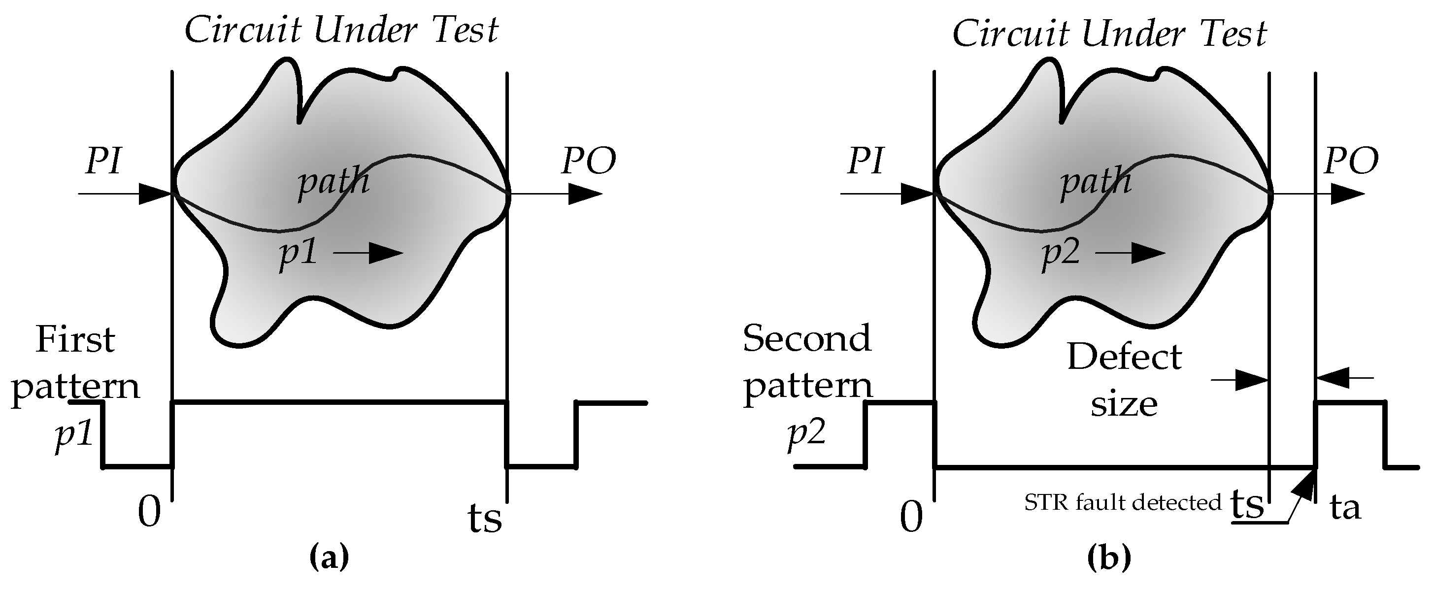
Figure 2.
Delay test architecture with its timing diagram.

Figure 3.
Principle of robust and non-robust PDF test.
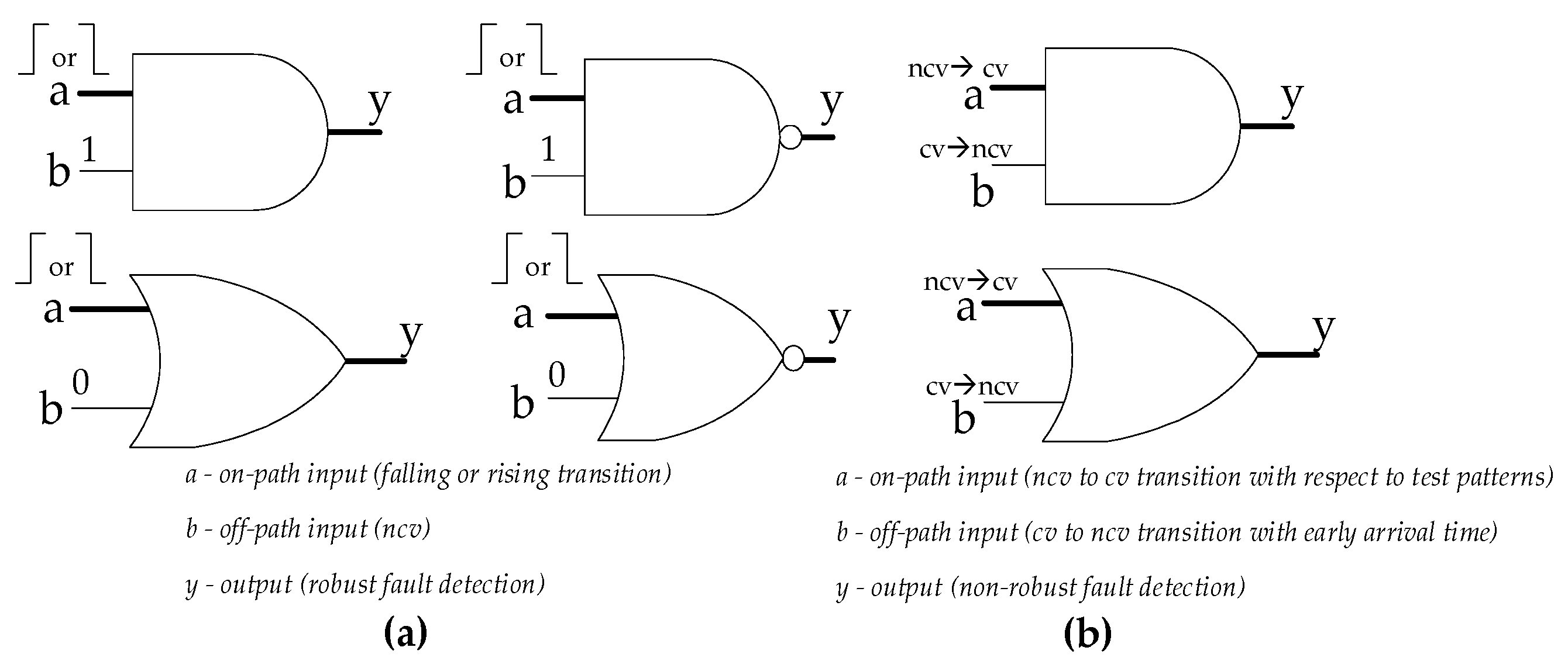
Figure 4.
Dependency of PDFs due to Common sub-paths in main paths.
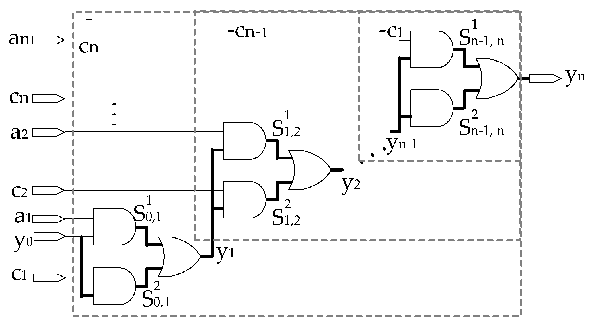
Figure 5.
Incremental Path Generation Procedure.
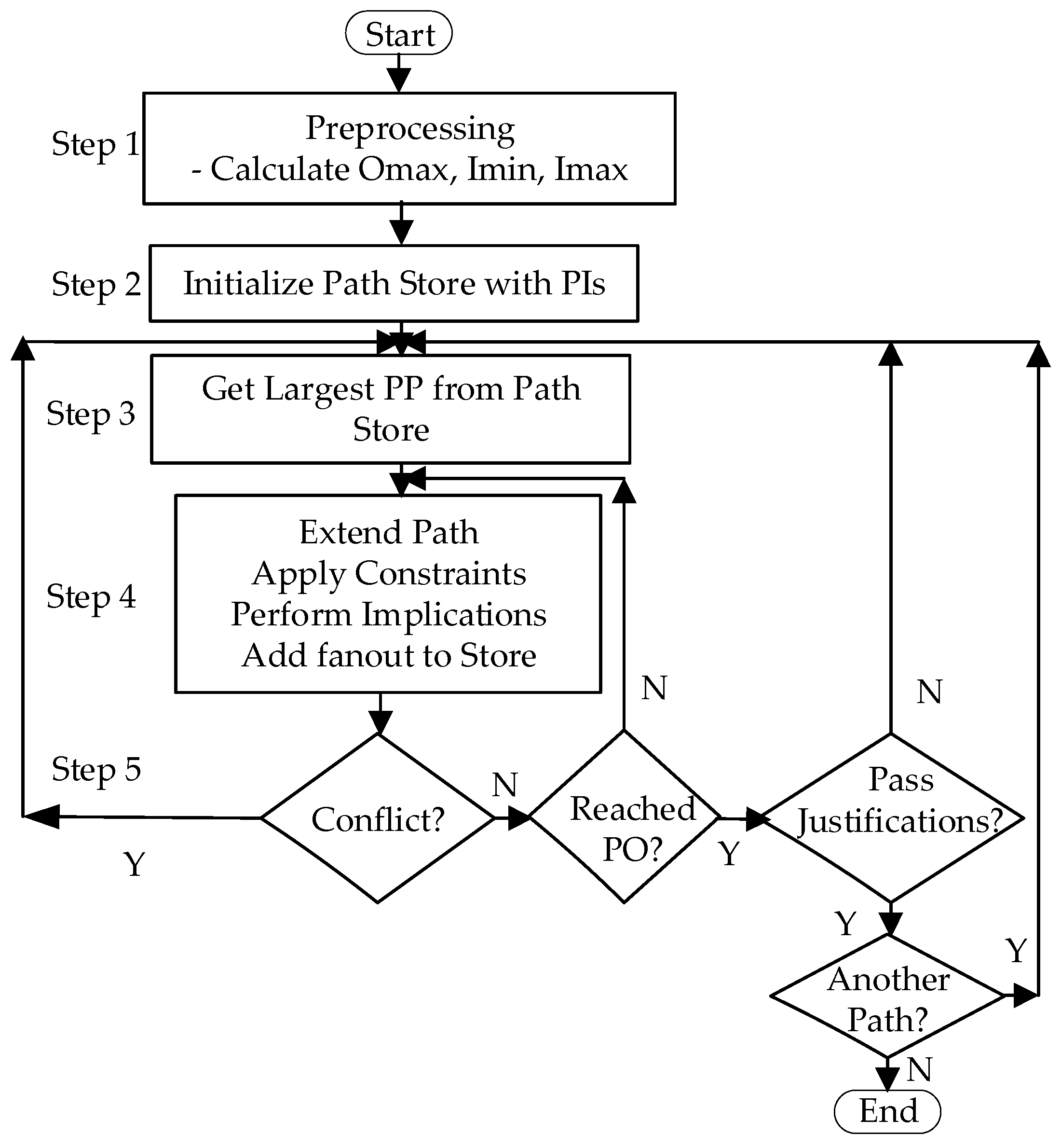
Figure 6.
Non-scan-based BIST setup for PDF Test.
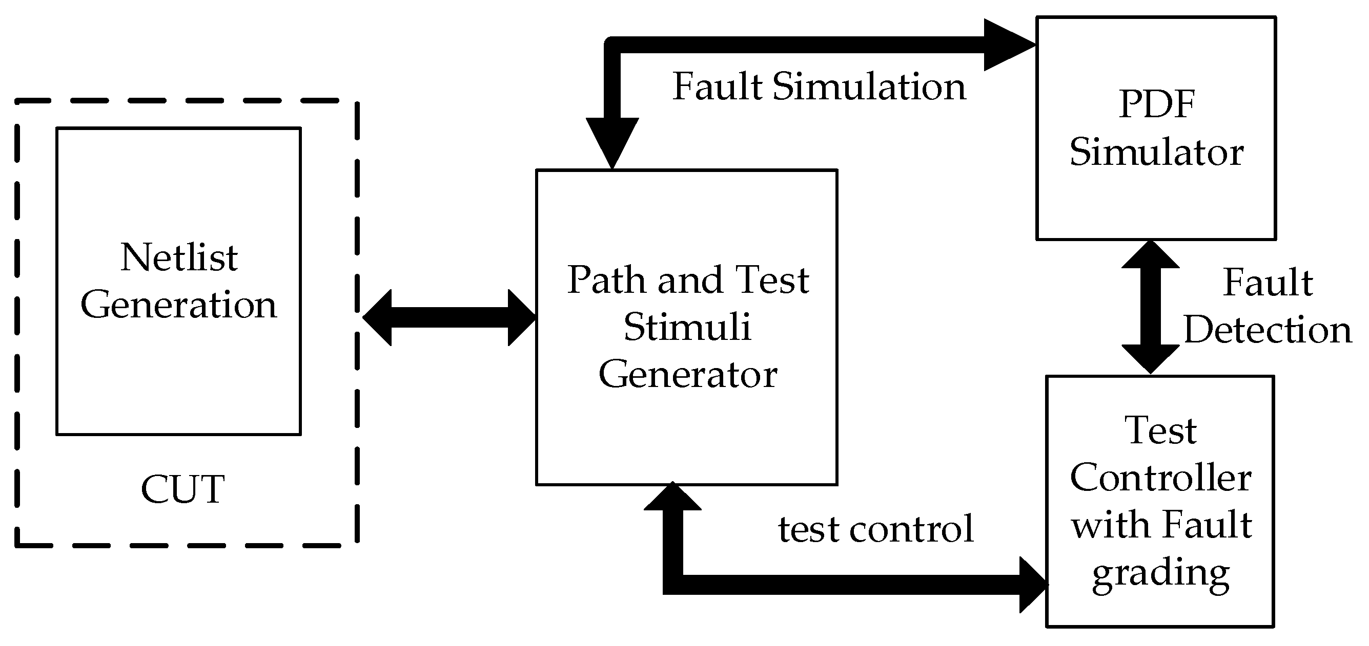
Figure 7.
SIC Test Stimuli Generation.
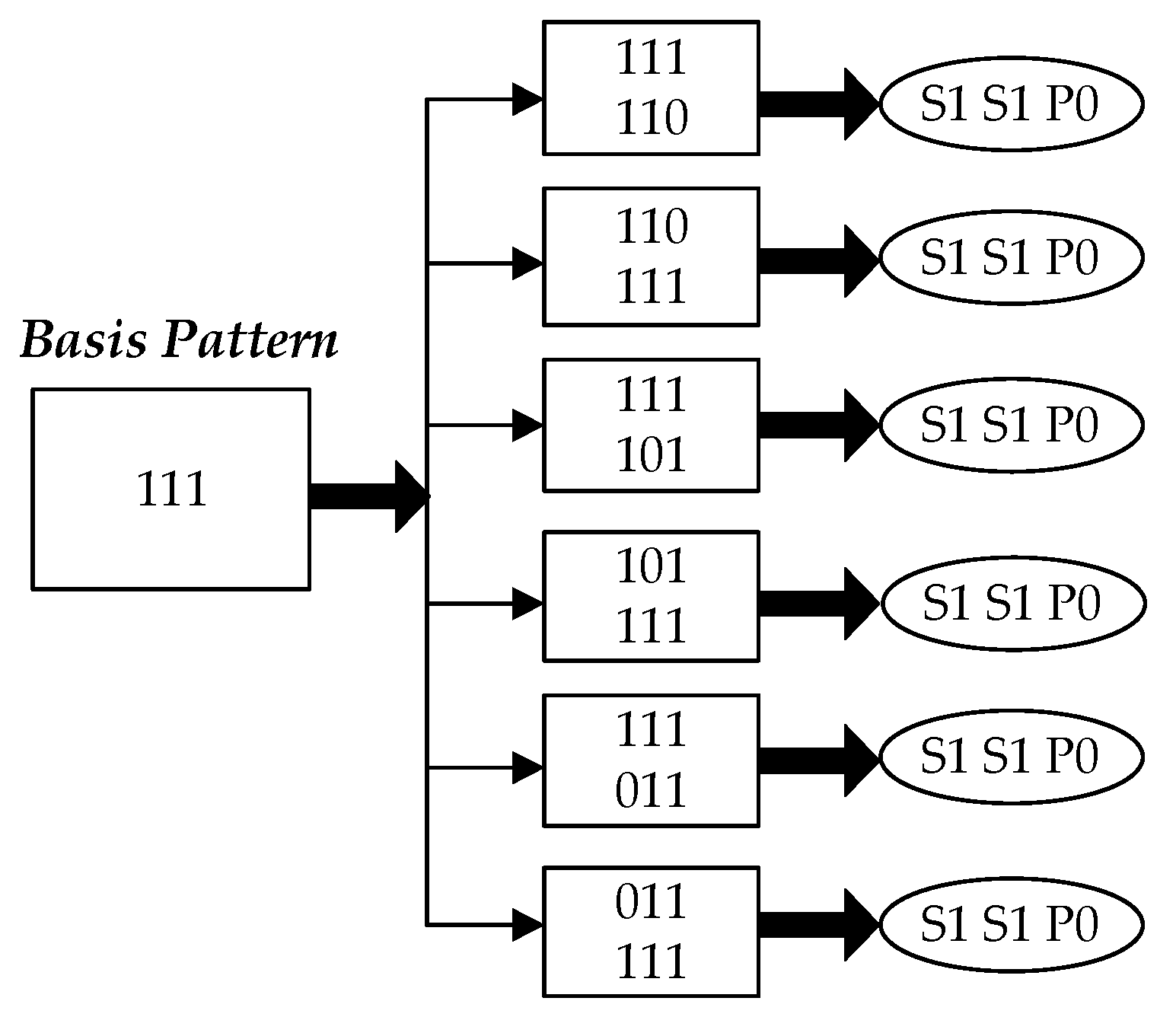
Figure 8.
A deterministic test set.
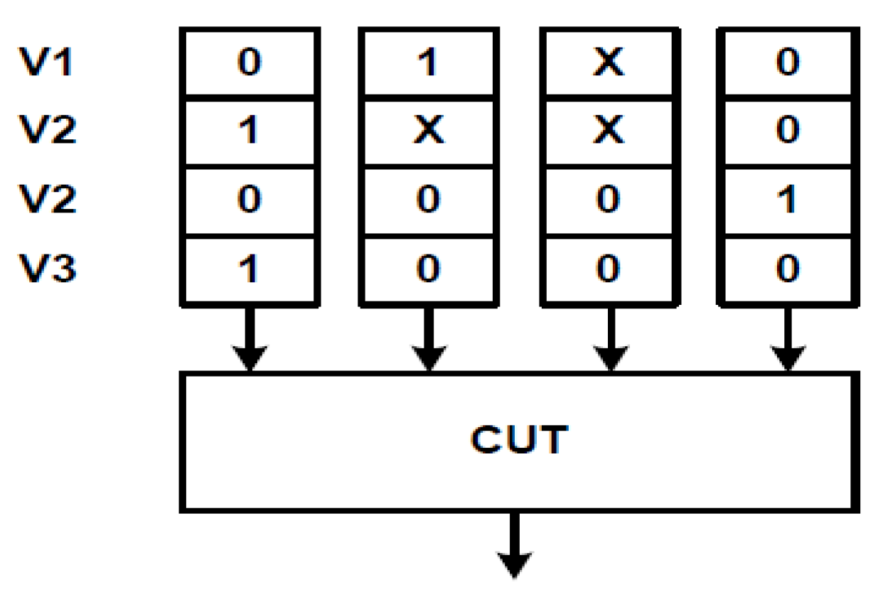
Figure 9.
Weights computation based on a deterministic test set for stuck-at faults.
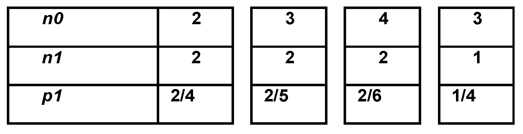
Figure 10.
Weights computation based on a deterministic test set for stuck-at faults.
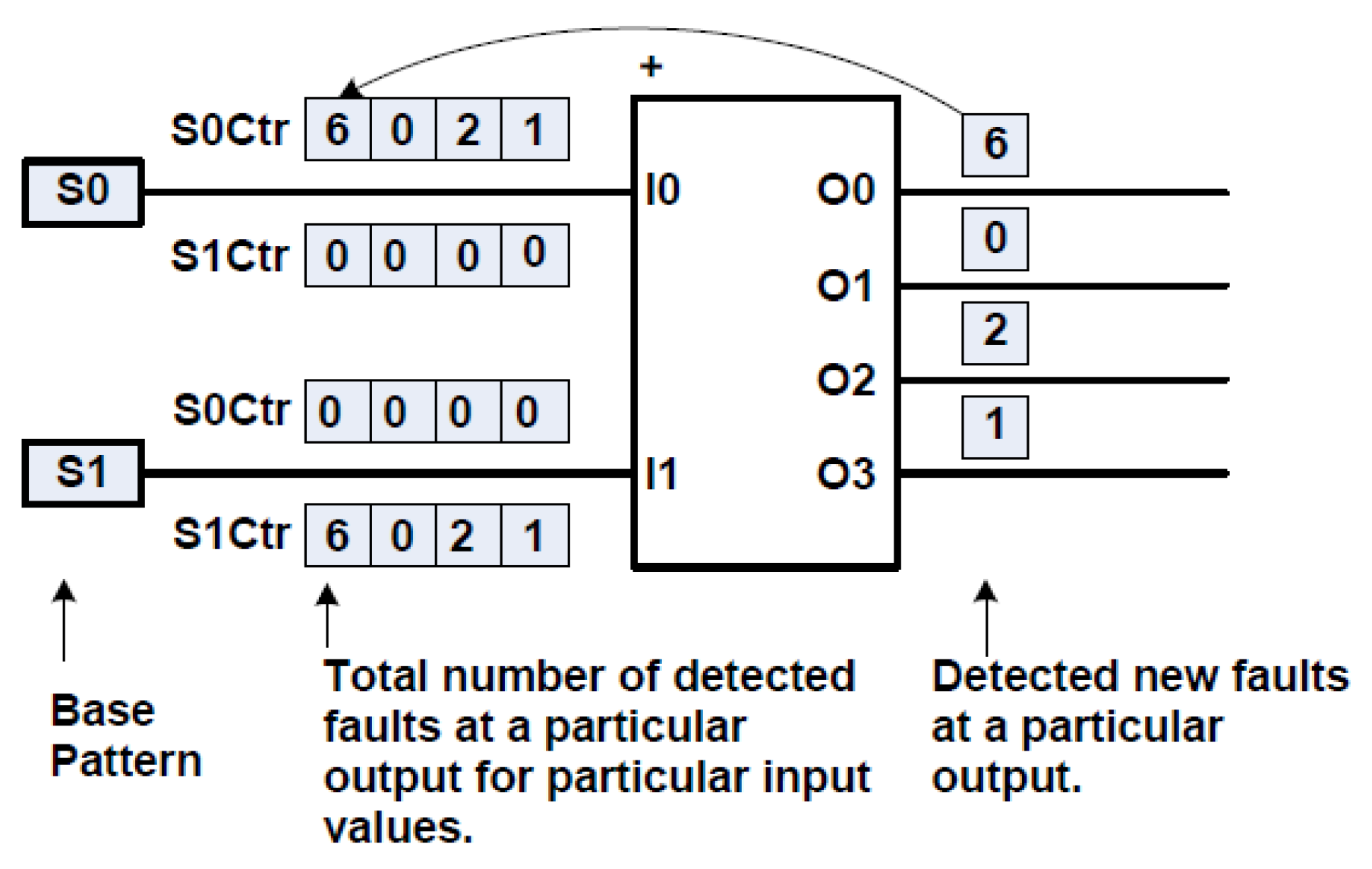
Figure 11.
(a) Assembly code implementation of A-PRG and (b) Output of A-PRG with N=4, C=1011 & I=1001.
Figure 11.
(a) Assembly code implementation of A-PRG and (b) Output of A-PRG with N=4, C=1011 & I=1001.
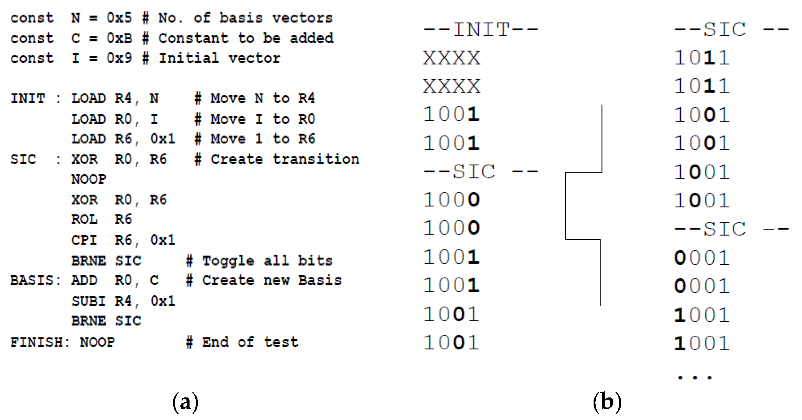

Table 1.
Encoding – Smith’s alphabet.
| S0 | S1 | P0 | P1 |
|---|---|---|---|
| 0 | 1 | 0 | 1 |
| 0 | 1 | 1 | 0 |
Table 2.
Instruction Set.
| Instruction | Description |
|---|---|
| LOAD Rd, k LOADI Rd, k |
Set the content of register Rd to [data stored in memory address k - immediate] |
| MOV Rd, Rr | Move content of Rr to Rd |
| ADD Rd, Rr ADDI Rd, k |
Add the content of [reg. Rr — immediate] to Rd. Store the result in Rd |
| ADDC Rd, Rr ADDCI Rd, k |
Add the content of [reg. Rr—immediate] with carry to Rd. Store the result in Rd |
| AND Rd, Rr ANDI Rd, k |
Bitwise AND operation of [reg. Rr — immediate] and Rd. Result is stored in Rd |
| OR Rd, Rr ORI Rd, k |
Bitwise OR operation of [reg. Rr—immediate] and Rd. Result is stored in Rd |
| XOR Rd, Rr | Bitwise XOR operation of Rr and Rd. Result is stored in Rd |
| NOT Rd | Invert the bits in Rd |
| ROL Rd | Rotate left the content of Rd |
| BRNE k | Set program counter to k if the equal flag is not set |
| CPI Rd, k | Compare register with immediate |
Table 3.
Encoding – Smith’s alphabet.
| Benchmark | Circuit type | Inputs/Outputs | Gates/Levels | Considered paths / Upper bound | Case 1: PDF Coverage (Before HT insertion) | Case 2: PDF Coverage (After HT insertion) |
|---|---|---|---|---|---|---|
| c432 | Channel Interrupt Controller | 36/7 | 203/18 | 10K/132K | 100% | 84.2% |
| c880 | 8-bit ALU | 60/26 | 469/25 | 10K/16652 | 100% | 89.1% |
| c1355 | 32-bit SEC Circuit | 41/32 | 619/25 | 10K/1110K | 100% | 82.3% |
| c1908 | 16-bit SEC Circuit | 33/25 | 938/41 | 10K/355K | 98.8% | 78.1% |
| c2670 | 12-bit ALU and Controller | 233/140 | 1566/33 | 10K/1306K | 89.5% | 72.2% |
| c3540 | 8-bit ALU | 50/22 | 1741/48 | 10K/12330K | 97.8% | 75.4% |
| c5315 | 9-bit ALU | 178/123 | 2608/50 | 10K/353K | 98.7% | 78.3% |
| c7552 | 32-bit adder/comparator | 207/108 | 3827/44 | 10K/282K | 98.3% | 81.1% |
Table 4.
Analysis of PDF coverage-based HT Detection.
| Benchmark | PDF coverage variation in % | ||
|---|---|---|---|
| Statistical Simulation trials | |||
| VMax | VMin | VAve | |
| c432 | 18.6% | 15.1% | 17.5% |
| c880 | 14.3% | 11.9% | 12.7% |
| c1355 | 19.3% | 17.4% | 19% |
| c1908 | 20.1% | 19.2% | 19.6% |
| c2670 | 18.4% | 14.3% | 17.8% |
| c3540 | 23.1% | 18.6% | 19.5% |
| c5315 | 21.6% | 17.2% | 18.9% |
| c7552 | 17.8% | 16.1% | 16.8% |
Disclaimer/Publisher’s Note: The statements, opinions and data contained in all publications are solely those of the individual author(s) and contributor(s) and not of MDPI and/or the editor(s). MDPI and/or the editor(s) disclaim responsibility for any injury to people or property resulting from any ideas, methods, instructions or products referred to in the content. |
© 2024 by the authors. Licensee MDPI, Basel, Switzerland. This article is an open access article distributed under the terms and conditions of the Creative Commons Attribution (CC BY) license (http://creativecommons.org/licenses/by/4.0/).
Copyright: This open access article is published under a Creative Commons CC BY 4.0 license, which permit the free download, distribution, and reuse, provided that the author and preprint are cited in any reuse.


