
Submitted:
12 November 2024
Posted:
13 November 2024
You are already at the latest version
Abstract
The increasing volatility of the markets and the growing demand for customized products are the challenges for the production of the future to ensure maximum flexibility and adaptability. This paper presents the development of a cyber-physical chain linking product features to requirements and their fulfillment in machine and process hardware to form a modular, reconfigurable production system. The conception and realization of universal production systems is investigated. A modular construction kit of individually combinable hardware and associated software modules is presented. These modules are coordinated via a digital process chain that enables holistic simulations, optimizations, and planning based on digital twins. This system is based on software-defined manufacturing but extends it into autonomous reconfigurable machines. The virtual planning and commissioning of entire production lines aims to achieve efficient and adaptable production in volatile markets.
Keywords:
Industry 4.0
; production science
; digital production
1. Introduction
The trend towards individuality and shorter product life cycles demands that modern production systems swiftly adapt to product changes [1] while maintaining a high degree of automation. To satisfy these demands, we propose software-defined value stream process systems (SVPS), which enable automatic reconfiguration of machine tools based on product requirements and machine capabilities.
Product changes, such as the need to change between process types in the value stream of a product or to change tolerance specifications for processes in a product, are the trigger for such reconfiguration. To optimize efficiency in production, the product features and the machine capabilities have to be considered equally. The task is to find a product that satisfies the customer's requirements and to find a machine configuration that is optimal for manufacturing this product.
Among the current production systems, reconfigurable manufacturing systems (RMS) offer the best potential for rapid, cost-effective adaptation while maintaining high productivity [2]. RMS utilize modular reconfigurable machine tools (MRMT), which can be reconfigured quickly to meet customer demands, as supported by Mehrabi et al. [3] and Padayachee & Bright [4]. These tools, designed for specific machining features, consist of basic and add-on modules that can be assembled or disassembled as needed. Extensive research has aimed at enhancing MRMT through open standards, control architecture, algorithms, and optimization metrics [5].
In Software-Defined Manufacturing (SDM) [6,7], integrating machines' physical behavior with digital machine images allows for complete digital planning and control, where physical processes follow digital specifications and machines can make automated decisions. However, manual intervention remains necessary, and production machines are often rigid and specialized. Agile production systems address heterogeneous product groups with limited usability [8]. Preliminary work in the Value Stream Kinematics project has explored eliminating the restriction of machine tools to specific processes using standardized kinematics based on six-axis industrial robots [9,10,11]. There remains a need for specialized machine tools with process-specific dynamic properties, especially for high-quality demand processes. Research has investigated adjustable damping systems to adapt machining stability [12,13,14].
In soft robotics, new concepts for continuously growing links (robot axes) are being studied, but these approaches primarily manipulate geometric dimensions and are mostly irreversible [15,16]. Other relevant technical properties for production machines remain unadaptable, and using polymer materials results in insufficient basic technical properties. Studies have only examined individual property adaptations, like stiffness or resonance behavior [17,18,19].
The critical aspect of automating the reconfiguration process is still missing. Addressing this gap is essential for faster changes and overcoming the skilled worker shortage. Our approach aims to bridge this gap by integrating SDM with MRMT into SVPS. This integration allows automatic reconfiguration based on specific product requirements. Using an electrical machine product as an example, this approach demonstrates autonomous reconfiguration from product design to mapping features to machine tools and kinematics.
2. State of the Art
A suitable software environment is necessary to enable the autonomous reconfiguration of the system and product features. In the SVPS environment, models for the machine, tools, and product, as well as interfacing models are required. A digital twin, which encompasses all machine and tool models, is required for digital planning and control (Section 2.1). An exemplary product is used as a demonstrator to validate the novel manufacturing system presented in this article (Section 2.2). The development of products for SVPS has excellent potential but faces specific challenges, such as aligning functional product requirements with design realization. Therefore, a product configurator is presented (Section 2.3). SVPS, which dynamically adapts to the specific products and their required quantities, requires a software-based selection of processes addressed by a process kit (Section 2.4). Furthermore, process simulation is needed (Section 2.5). A machine kit is used to adapt the characteristics of machine tools to the different requirements of manufacturing a specific product (Section 2.6).
2.1. Digital Twins
As described above, autonomous planning and execution of manufacturing processes require a digital representation of all components involved in production. This representation is often referred to as a digital twin, although there is no generally accepted definition of the term “digital twin”. Generally, a Digital Twin is a virtual representation of a real object, system, or process with which the real counterpart's properties, states, and behaviors can be calculated, simulated, and controlled [20]. As such, it is an essential component of digitalization and Industry 4.0. Digital machine images depict the physical behavior of machines and the resulting interactions for product manufacturing [7]. Their integration in the SDM context enables complete digital planning and control of production [6]. An essential aspect of the digital twin is that it not only imitates real behavior but can also be used to analyze the properties and behavior under different environmental and boundary conditions. The real object can thus be influenced by feeding back suitable signals.
A distinction can also be made when implementing digital twins based on the degree of integration. Kritzinger [21] provides a proposal for the classification into digital model, digital shadow, and digital twin:
Digital Model: a digital representation of an object without automated data exchange between real and digital objects. This can include simulation models that use physical data for the creation of the model but with manual data exchange, so physical and digital models don't affect each other.
Digital Shadow: a digital representation with an automated data flow in one direction from the physical to the digital object. A change of the real object leads to a change of the digital object.
Digital Twin: a digital representation with an automated data exchange in both directions. This means that the digital twin not only represents the current state of the physical object but can also be used as a controlling instance for the real object. A visual representation of this is given in Figure 1 below.
This categorization is used within this paper with the term digital image for general description and when it is irrelevant.
In addition to the lack of a standardized definition, there is no standardized format for describing a digital twin and its physical properties. The characteristics of digital twins are highly dependent on the application [22]. This also means they are usually created with a specific application in mind and are not very flexible for other applications. There are several approaches to creating a framework for digital twins to reduce the effort required to create them [23,24].
One aspect of the digital model of machines that is particularly relevant to this work is the description of machine kinematics and dynamics. A common option, which is mainly used in the robotics field, is the Unified Robot Description Format (URDF), which describes the kinematic and dynamic parameters in a standardized text file (XML) and can be used by various simulation and visualization environments [25].
2.2. Product: Electrical Machine
The definition and design of a sample product enable extensive testing of the new production system. In this case, an electrical machine (EM) is utilized as a demonstrator product. EMs are electromechanical energy converters using magnetic energy as an intermediate energy form and unintentionally converting fractions of the power flow to heat. Consequently, the four physical domains of mechanics, electronics, magnetics, and thermics influence the resulting and achievable product behavior during operation [26]. Therefore, an EM consists of subsystems that individually fulfill subfunctions from one or two of the mentioned domains. The latter is the case if the subsystem fulfills an interface role between different domains. The interactions between individual subsystems vary greatly in the number and complexity of their interdependencies and form a highly complicated overall system behavior [27]. Particularly in the active zone of the EM, there are diverse and highly non-linear interactions between the four domains mentioned and the subsystems involved, such as the coil winding system, the soft magnetic cores, the cooling system, and the structural components that absorb the mechanical loads [28]. However, for the actual operation of an electrical machine, additional peripheral subsystems not located directly in the active zone of the EM are usually required. Examples of these subsystems are the bearing system, the sealing system, or the bearing shields [26]. Located outside the active zone, these subsystems are characterized by less interaction with the other domains, so the subsystems mentioned mainly fulfill mechanical functions. Accordingly, the density of functional integration is lower for these peripheral subsystems, which leads to increased manufacturability. Therefore, starting from the peripheral subsystems and moving on to the subsystems belonging to the active zone, EMs offer the possibility of testing and further developing the novel production process at increasing levels of difficulty [29,30]. However, a suitable type and design of the electrical machine must be elaborated to fulfill these desired properties.
2.3. Product Configurator
The development and manufacture of products for SVPS offer significant potential for the future design of production environments. To fully exploit this potential, the specific challenges and requirements that must be considered when designing such products must be identified. One challenge is the type of information in the product models used [31,32]. A critical aspect in this context is aligning functional product requirements with their design realization during product development [33,34]. To date, there are no methods to ensure the functional quality of the products to be manufactured [35].
2.4. Process Kit and Process Modules
The current state of research in end effectors for process technologies such as milling or component handling is on permanently installed and non-convertible systems. Verl et al. [36] gave an overview of current developments in industry and research on industrial robots (IR).
Consequently, current production systems often lack the necessary adaptability and scalability to effectively respond to the rapidly evolving and variable demands of contemporary markets up to now, there have been approaches for an adaptable production system, as demonstrated by Möhring [37], but other methods have tended to exist as isolated solutions as shown by ElMaraghy et al. [38]. Therefore, a primary objective should be to advance the development of universal production systems, which serve as cost-efficient and sustainable solutions for achieving adaptability in manufacturing processes. For instance, one approach being pursued involves adapting existing production systems by utilizing and interconnecting sensor and actuator data. This strategy aims to evolve these systems into Self-Optimizing Manufacturing Systems (SOMS), which can autonomously enhance their performance and efficiency [39].
To realize a versatile and sustainable production for the future, this approach needs to be expanded beyond its current scope to include broader aspects of software and hardware integration, as Bergs et al. show [40]. The outcome of this expanded approach is a production system that dynamically adapts to the specific product and its required quantity. This system can be reconfigured or repurposed in a modified form, thereby establishing a modular framework composed of interlinked subsystems, including hardware and software components. Bleicher et al. have summarised approaches for sensors and actuators in production systems through intelligent tools [41].
The processes must first be characterized to make a software-related selection of processes for certain products make a software-related selection of processes for certain products, the processes must first be characterized. According to DIN [42], manufacturing processes can be fundamentally categorized into the main groups: "primary forming", "forming", "cutting", "joining", "coating", and "changing material properties" (source). Contrary to the "universality" approach, SVPS is looking for reconfigurable, process-specific solutions that, when combined, can implement almost any manufacturing process chain on a diverse range of components to manufacture a wide variety of products in a software-driven, demand-orientated manner. Based on a decomposition of exemplary production parts, a solution space consisting of process modules to be provided ad hoc is initially defined here. Each process module is characterized by its technology (e.g., FDM 3D printing, milling, joining, gripping), a characteristic parameter field (e.g., performance, speed, gripping range), and capability features (e.g., range of materials, accuracy, rigidity). Finally, the integration of sensor technology is analyzed, providing the subsequent information sources for digital images.
2.5. Process-Simulation
Commercially marketed CAD-CAM systems make it possible to recognize features on components from the design and to derive manufacturing operations to a limited extent. A focus on artificial intelligence was also used early on to identify different features. In 2001, Öztürk [43] presented a neural network for recognizing non-standardized complex shape features. Using CAD-CAM systems, these recognized geometric features can be assigned to machining processes. However, machine influences on component quality and tolerances are not considered. For this reason, a conservative process design is used, which does not utilize the existing performance and rigidity of the machine to avoid critical components or machine states. As a result, machines are oversized in rigidity and drive power, resulting in large moving masses and unnecessary energy consumption.
However, if machines are undersized for a process strategy, this can lead to tool failure due to overloading caused by vibrations or excessive deviation of the process variables. In addition to damage to the tool, the required component qualities and tolerances cannot be met [44].
2.6. Machine Kit
Machine tools comprise four main assemblies critical to generating relative motion between the tool and the workpiece: the frame, the guideway, the drive, and the control system. The frame is the machine's structural foundation, holding components in place and absorbing mechanical and thermal loads. Frames are designed as open or closed structures depending on the machine's force flow, with open frames offering better accessibility at the expense of potential structural deflection under machining forces. Guides mounted on the frame are integral to the precise guidance of axis movements, facilitating the accurate execution of both rotary (rotary guides) and linear (linear guides) motions. Drives convert electrical, hydraulic, or pneumatic energy into mechanical energy, distinguishing between primary motors for energy conversion and gears for mechanical energy conversion. They include main and auxiliary drives for specific tasks requiring high dynamic and static drive stiffness and high geometric and kinematic accuracy [45]. Machine tool controls automate operations and guide tools along programmed paths to shape workpieces. Key components include input sensors, processors, and output actuators. To facilitate flexible production, control systems must be adaptable, capable of rapid reprogramming, and equipped with real-time monitoring, simulation, and adjustment capabilities.
The design of these essential machine tool components, particularly the frame and guideways, prioritizes balancing structural integrity with the precision required for effective operations. In contrast, drives necessitate high stiffness and accuracy to function optimally. Modular and reconfigurable machine tools have established themselves as vital solutions to address the need for flexibility and efficiency in production.
These tools facilitate rapid reconfiguration through interchangeable modules, significantly reducing the development and setup time associated with new product cycles. This modular approach was highlighted in research by Heisel & Michaelis in 1998 [46] and further explored by Abolhassan in 2013 [47].
2.7. Research Gap
In conclusion, enabling autonomous reconfiguration in production systems requires a robust software environment, with the digital twin playing a key role in digital planning and control. While this technology shows great potential, challenges such as the lack of a standardized definition and format for digital twins limit their flexibility across different applications. The chapter also highlights the need for a product configurator to address the gap in aligning functional product requirements with design realization. Additionally, while process kits and simulations offer adaptability, there is still a need for more advanced methods to account for machine influences on quality and tolerances in process design. Current solutions for modular and reconfigurable machine tools demonstrate the potential for flexible production. However, further research is required to develop universal systems that can dynamically adapt to varying product demands in real time.
3. Software-Defined Value Stream Process – Conceptual Process Chain
The advancement of autonomous reconfiguration in production systems depends on a flexible software environment, with digital twins central to digital planning, process control, and real-time adaptation. However, challenges remain, including the lack of standardized digital twin definitions and limitations in aligning product requirements with design realization.
The Software-Defined Value Stream, as part of SVPS, is introduced as a solution to address these issues. SVPS integrates digital twins, modular, reconfigurable machine tools (MRMTs), and process simulations to create an adaptable production environment. It optimizes product design, manufacturing, and quality assurance using a product configurator, CAD/PMI models, and machine kits, offering a dynamic, reconfigurable solution.
This chapter presents the conceptual process chain for SVPS, detailing the steps from product design to realization on the machine. An overview is shown in Figure 2. This chapter outlines the conceptual process chain for SVPS, focusing on four major steps:
- Product Design using the Product Configurator (Section 3.3), where the Product (Section 3.2) is designed and made available as a CAD or PMI model.
- Process Strategies are defined through Process Simulation (Section 3.5 optimizing the tool path, manufacturing technology, and system requirements under set constraints. ) The Digital Twin (Section 3.1) maps the requirements of the product and process to the capabilities of the machine.
- Process Controllability leverages the Digital Twin, along with the machine kit (Section 3.6 and Process kit (Section 3.4), to configure the machine in a virtual space before transitioning to the real world.
- Implementation is achieved through the real machine Demonstrator, enabling flexible manufacturing of the realized Product, followed by quality assurance, with empirical data fed back into the Product Configurator for continuous improvement.
The modules within steps 1-3 will be discussed in detail in the following sections.
3.1. Digital Twin
The common vision described in this paper is to autonomously plan the manufacturing process from design to product manufacturing. This requires a digital work chain consisting of different work steps (modules). All modules require a digital image corresponding to at least a digital shadow and, in some cases, a digital twin. These digital images enable the digital planning process, as outlined in Figure 2, starting from the product and ending in a physical demonstrator.
A unified structure must be created for these digital images to represent planning consistently and autonomously. Strictly speaking, two structures of digital images are required: one for the product and one for the machine. The digital mapping of the product is the task of the product configurator and its underlying systems. The digital twin of this part focuses on the machine side and production.
The resulting requirements are
- Mapping of (simplified) production processes or simulations
- Mapping of the physical machine modules
- Mapping of the processing modules
-
Mapping of the production system, which is made up of smaller components
- Mapping of the kinematic boundary conditions
- Mapping of dynamic properties
- Feedback of relevant sensor and production data
The digital image of the modular system modules, therefore, contains the following: A URDF file to describe the geometry and kinematic structure, CAD data, characteristic values of the mechanical modules (simplification as a multi-body model for dynamic simulation), a standardized display of existing sensor data from the module and a defined XML structure for reading out the characteristic data. The required characteristic values are also added for activated components, whereby only the electrical energy supply is initially considered. Modules for processing contain interfaces for connecting the process simulation and introducing process forces. The kinematic description of the individual modules also includes joints for linking with other modules so that they can be combined as required in an automatic configuration to form a complete machine. The structure of the digital twin is shown in Figure 3.
The data is displayed in this structure and will be used in the various steps of production planning. The details of the multiple modules and the specific processing in the individual steps are described in more detail in the following sub-chapters.
3.2. Product: Highly Modularised Electrical Machine
The novel manufacturing process requires extensive test scenarios and assemblies to test the process chain and the contained sub-processes. Furthermore, the test assemblies must be designed uniformly and as a self-contained unit to ensure the feasibility, repeatability, and comparability of tests while evaluating the effects of deviations on the behavior of the end product. For this reason, the principle of modularization is used to divide the different zones of the electrical machines into modules, increasing the manufacturing difficulty. With regard to modularization, a special type of electrical machine known as an axial flux machine is selected as a demonstration product [48]. For this type, the magnetic field passes through a disc-shaped air gap, mainly in the axial direction. In contrast to the common radial flux machine, which has a cylindrical air gap, the axial flux machine offers geometrically uniform sub-segments that can be stacked axially, even when realized with multiple air gaps [49]. Using fixed modules, products that can be flexibly customized in terms of performance and installation space can be manufactured and evaluated in the early stages of testing and implementing the new manufacturing process.
For the axial flux machine, the modules bearing shield (front and back), shaft segment, housing segment, rotor disc (outer and inner), and stator ring are defined. These modules require increasing tolerances and degrees of integration and thus are more difficult to produce. The first design of such an axial flux machine, showing the mentioned modules, is given in Figure 4.
The testing of the novel production process will first be trialed on the comparatively simple modules, i.e., the housing segment and the bearing shields. However, several combined process steps are already necessary for these modules, as additive steps must be supplemented by subtractive steps to achieve the desired shape and position tolerances, e.g., in the bearing seat of the bearing shield, thus enabling smooth operation of the resulting product.
With ongoing development of the entire manufacturing process, increasingly complex modules and the resulting end products are being tested. As the autonomous stage of the production process is approached, the modules and interfaces are made increasingly flexible, and the resulting complexity is no longer a problem.
3.3. Product Configurator
A product configurator is being developed to improve the alignment of functional product requirements with their design realization during product development (see Figure 5).
To improve alignment, a product configurator is being developed to enable designers to acquire the necessary knowledge for function modelling. This configurator helps by modelling the product and effectively illustrating the interactions between design requirements and their implementation in production. It is vital to consider the interactions between production processes and the functional requirements of the product subsystems to successfully produce the product.
The product configurator plays a key role by identifying when human approval is needed after an optimization step in its process chain and which adjustments to the product design the system can autonomously make to optimize production processes. The aim is to guide a product from the functional requirement stage through the design phase and into production while supporting the optimization of the production process chain to fully utilize the potential of SVPS.
A modular product configurator is being developed as a design demonstrator. This configurator allows for the exploration of design principles and the development of solutions to fully exploit the potential of SVPS and optimize manufacturing processes. The configurator's flexibility in customization and configuration enables efficient and customer-oriented production.
3.4. Process Kit
Figure 6 shows an end-effector (EE) that can adapt to the production-related requirements of a product and map various manufacturing processes in the additive-subtractive process chain. Furthermore, the EE can use integrated sensors and intelligent tools and components to record its status and use the data obtained by the actuators to counteract process deviations, e.g. drifting of the milling cutter or unwanted vibrations.
To determine which parameters the multi-process EE must-have, a virtual process kit is created that selects the necessary processes based on the product to be manufactured. For this purpose, a comprehensive solution space consisting of various process modules and their technological properties will be defined. Technologies such as FDM 3D printing, milling, joining, and gripping are considered. A characteristic parameter field describes the solution space, including power, speed, and gripping range. Furthermore, the capability characteristics of the process modules, including the material spectrum, accuracy, and stiffness, are presented in detail.
A central aspect of this work package is the abstraction of the processes using metadata to enable software-controlled selection, configuration, and combination of the process modules in the virtual solution space. This includes the definition of process chain configurations that consider the requirements of the individual technologies and the process combinations that can be realized and excluded.
Another focus is the conception, design, and construction of a multi-process-capable EE. This involves analyzing how the various process modules interact with each other and what effects these interactions have on the geometry, surface, and edge zone of the component.
The integration of sensor technology is being analyzed to complete the digital image of the processes. Sensors serve as a source of information to enable precise and comprehensive data acquisition, which is essential for software-driven process control. These investigations are intended to create a solid basis for developing flexible and adaptable manufacturing processes that meet the increasing demands for precision and efficiency.
3.5. Process Simulation
The process simulation of the machining serves to identify the framework conditions that the manufacturing system must provide. As an example, the housing of an axial flux motor is considered to be the housing that is additively manufactured. The required precision for a bearing seat, into which a ball bearing is pressed, is to be achieved by machining the housing while it is still in the additive process. The additive process is not able to achieve the required tolerance. As the component must remain on the build platform for the subsequent continuation of the additive process, machining is carried out by milling. The process optimization for this component should be carried out as described below.
Production planning uses commercial CAM tool planning to specify different machining strategies for a range of tools. Input parameters are, on the one hand, the tools available in the system and, on the other hand, technological target values such as precision and surface quality that must be achieved. The tool paths are calculated based on these input parameters. Various machining strategies for roughing and finishing are considered. As an insufficiently defined offset has been added to the functional surfaces to be machined, a defined offset consistent with the final geometry is required to produce high-precision components. This can be ensured by a roughing process followed by a semi-finishing process, which leads to longer machining times. The tools also influence the machining process, as maximum axial and radial infeed depend on them and, therefore, the process forces that occur. Machining strategies such as trochoidal milling have a further influence, which reduces process forces but requires higher dynamics from the manufacturing system. The surface quality can, in turn, be influenced by the feed rate of the tool; if this is set high, clear feed marks remain on the surface.
After configuration of different machining strategies, evaluation and ranking are carried out. The required target values are compared with the predicted ones, and the production system requirements are defined. The weighting of the target variables can range from simple factors such as manufacturing time to complex, predictable variables such as the expected dimensional accuracy. The requirements can be conflicting and influence each other, which requires an optimization and a balancing of the target values. In addition to ranking the machining strategies from the portfolio, the specific technical requirements that the manufacturing system must fulfill are analyzed. This includes the calculation of dynamic loads from the tool paths and accelerations, as well as the estimation of process forces from machining using suitable simulations. Process forces are estimated in critical areas where high dynamic loads are superimposed with process forces or where the component contour leads to large tool penetrations. This can be done using simple cutting force models like the Kienzle model.
In addition to the forces that occur, the manufacturing system must also be able to absorb dynamic excitations of the structure and provide sufficient damping. These excitations are caused, among other things, by the engagement frequency of the tool, which can be calculated based on the geometry and speed. These frequencies are usually high in the range of several hundred Hertz. Also, cyclical movements of the tool paths lead to dynamic, mostly low-frequency excitations. For example, trochoidal milling can lead to an excitation frequency due to the constant circular movement of the tool path. Process planning results in the definition of the process strategy that best fulfills the requirements of the component and optimally considers the limiting conditions. In addition to the basic machining strategy, which contains technology and path information, the determined requirements are also passed on to the manufacturing system.
If the production system is unable to perform these requirements, the control system reports this to the process planning. This removes the selected strategy from the portfolio of possible processes and re-evaluates the machining strategies. The newly selected strategy with the best ranking that fulfills the framework conditions is passed on.
3.6. Machine Kit
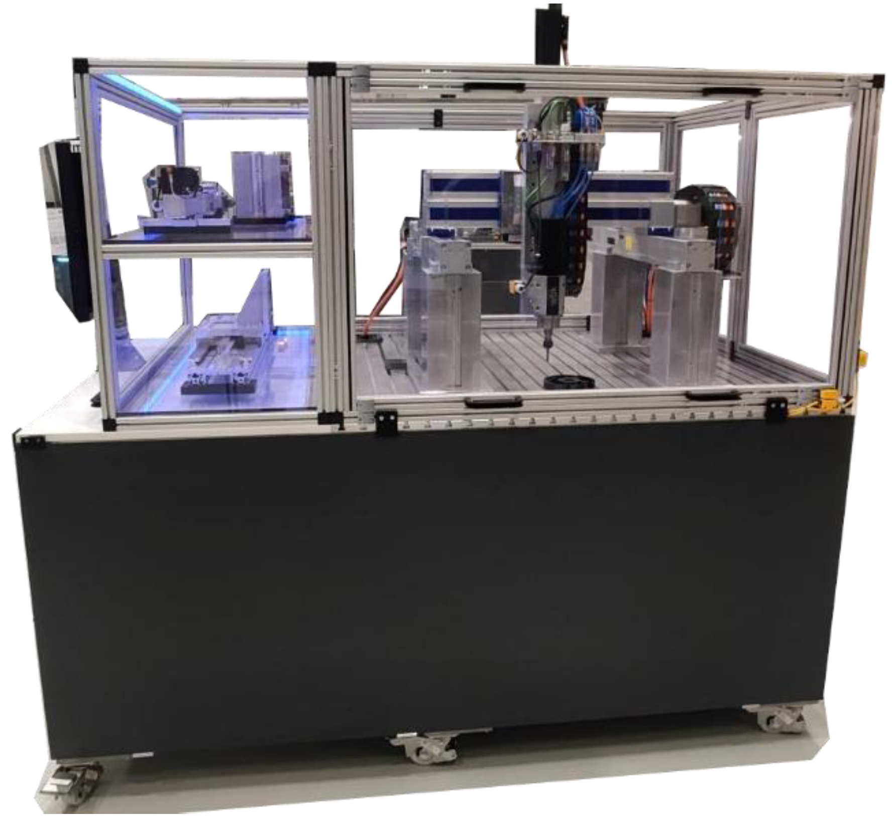
The process requires a suitable MRMT designed to autonomously adapt its configuration based on process requirements, specifically workspace, process forces, and chatter. The demonstrator, as shown in Figure 7, provides this flexibility. It achieves this flexibility by utilizing a modular setup consisting of interchangeable machine axes connected through standardized interfaces. This modular design allows the machine to adjust its kinematic and dynamic properties to meet the specific demands of each manufacturing task, enabling highly versatile production.
The demonstrator can reconfigure itself by selecting and combining different axes based on the task trajectory and the process forces involved. For example, the workspace can be adjusted via length-adaptable axes to match the product's size, eliminating the need to oversize the machine for future requirements. Unused axes are stored in a designated area for swift changes, minimizing downtime during reconfigurations.
The demonstrator features a customizable frame with a working area of 1.3 by 1.3 meters, and it includes essential components such as safety housing, control electronics, and human-machine interfaces. It is designed to execute various manufacturing processes, including milling, FDM 3D printing, and joining, each requiring different machine configurations. The milling operations require a robust machine configuration. Here, the heavy-duty axes are arranged as a reinforced gantry structure that ensures enhanced rigidity, which is crucial due to the significant forces encountered during milling. Furthermore, milling may induce chatter into the system due to process forces exciting the machine structures' natural frequencies. To reduce the chatter, a module to shift the natural frequencies of the structure has to be designed.
The fused deposition modeling (FDM) process does not necessitate high rigidity but instead benefits from agile and dynamic machine movements. A lightweight kinematic structure is optimal for this process, enabling rapid and efficient production dynamics. This lightweight kinematic structure also benefits from machine axes with high acceleration profiles, such as belt-driven axes, which are selected for this process. Another consideration is the workspace, where state-of-the-art machines have a fixed workspace and, therefore, have to be designed for the largest possible future product; this demonstrator can adapt its workspace to the product via length-adaptable axes.
Figure 8.
Concepts for length-adaptable machine axes, one with continuous length and one with discrete modules.
Figure 8.
Concepts for length-adaptable machine axes, one with continuous length and one with discrete modules.
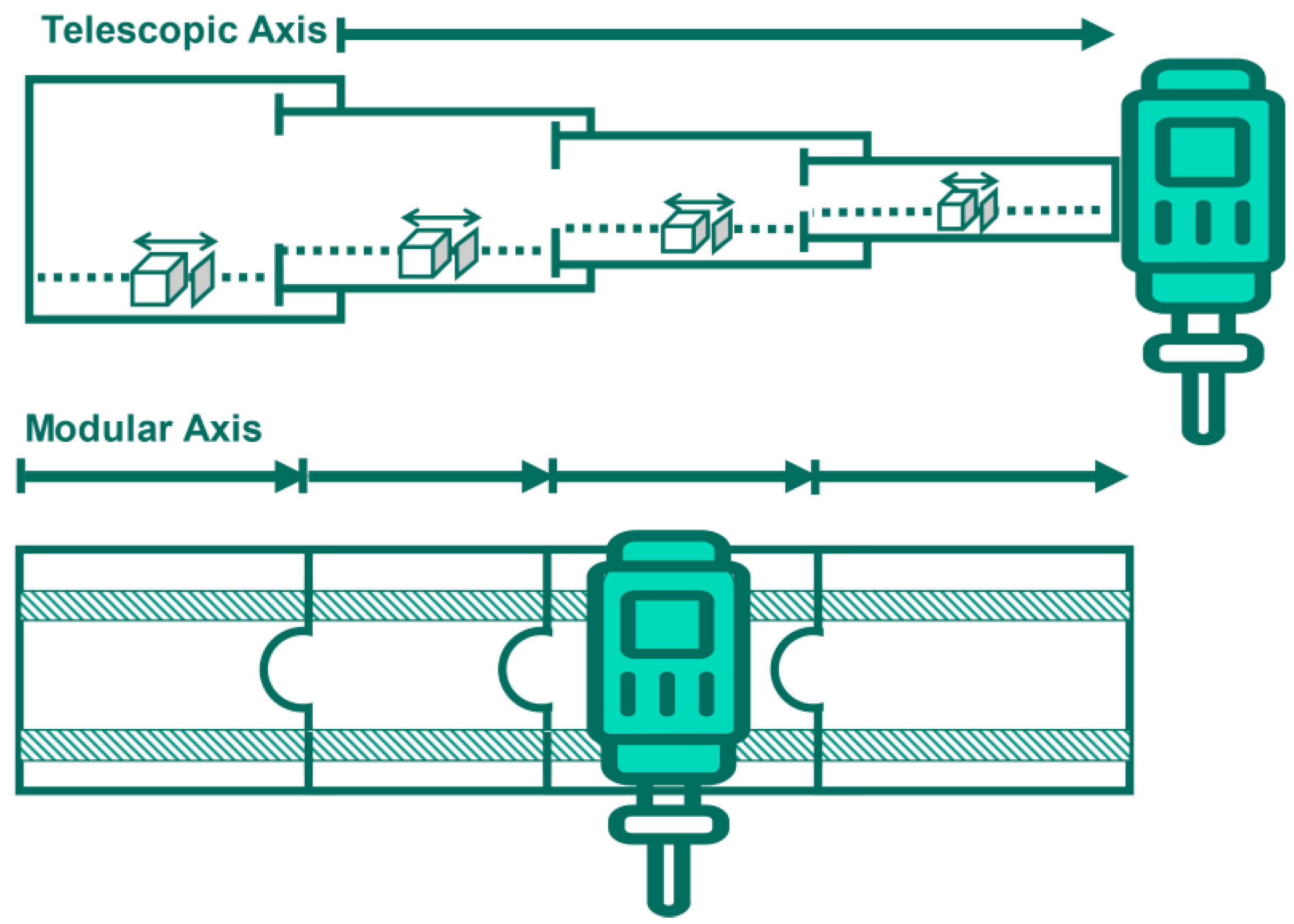
Kinematic parametrization refers to modifying the physical movement and configuration of machine components to adapt to different production needs, such as product sizes. To deal with such changing requirements, two main approaches are considered. The first is “growing” axis systems such as telescopic mechanisms, which allow machines to adjust their size automatically and facilitate continuous production without manual intervention. Another approach utilizes extendable modular systems that, while requiring manual setup, are simpler in design and easier to implement. Such systems might include technologies like linear direct drives or pinion drives, which can be adjusted to suit the specific dimensions needed for different tasks.
Figure 9.
Concept for changing machine dynamics uses internal or external stiffness-adaptable machine axis.
Figure 9.
Concept for changing machine dynamics uses internal or external stiffness-adaptable machine axis.
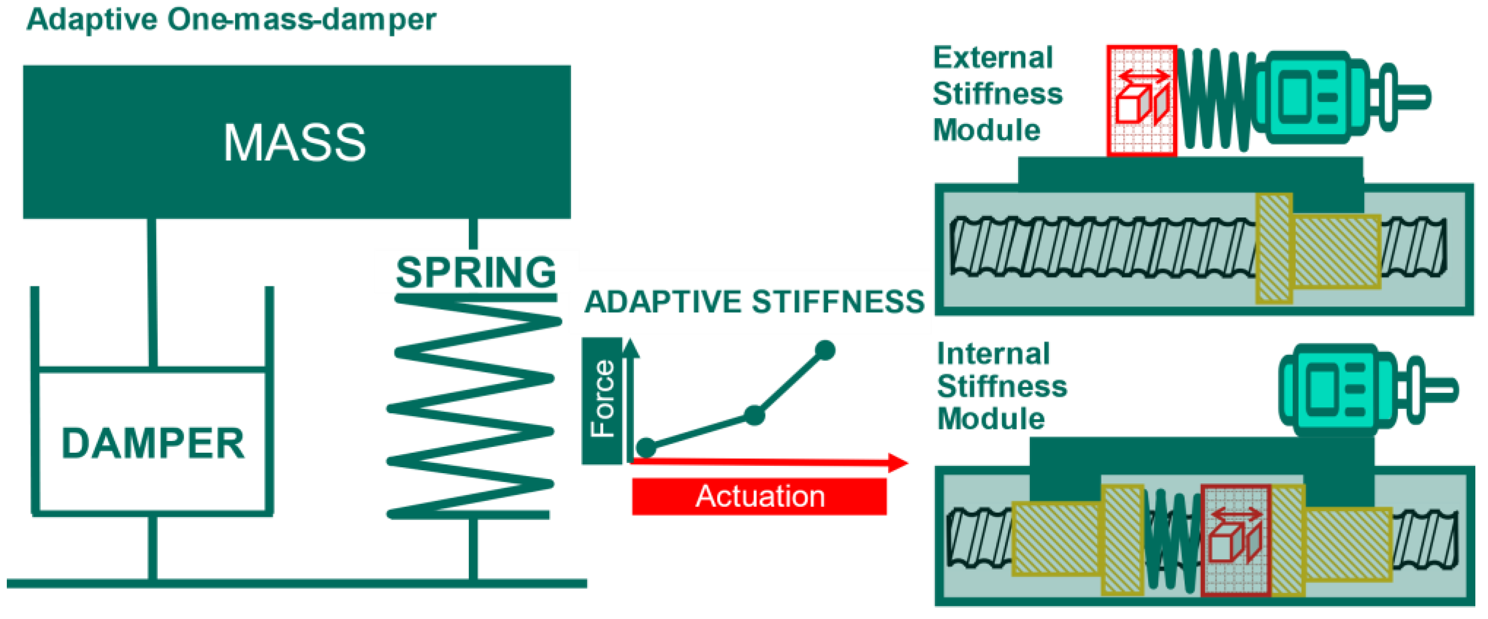
Dynamic parametrization focuses on modifying the mechanical properties, such as stiffness and damping, of machine components to optimize their performance under different operational conditions. This capability is essential for maintaining high precision and stability in production, particularly when dealing with varying process forces and speeds. Plans include enhancing the dynamic characteristics by developing adaptive stiffness modules, which can change their stiffness by preloading springs using an actuator. This technique improves the dynamic stiffness of the machinery, which is crucial for processes requiring high precision, like milling. Another module, which is placed between the ball screw drive and spindle, could also be used to change the stiffness of the structure.
Furthermore, safety measures such as protective housings and sensors are integral to the setups, ensuring a secure production environment. These systems also have to be modular to ensure safety when switching between different axis configurations. The final demonstrators should then be able to showcase the flexibility and adaptability of modular machine tool systems by covering a wide range of machine kinematics and dynamics.
5. Discussion and Conclusions
This project addresses the key challenge identified in the research gap: the need for a higher degree of automation in modular and reconfigurable machine tools (MRMTs), which are currently reconfigured manually. We have laid a solid foundation by developing the software and hardware tools necessary to enable autonomous reconfiguration in MRMTs. SVPS integrates digital twins, process simulations, and modular, reconfigurable systems to bridge the gap between product requirements and manufacturing capabilities.
Our work demonstrates significant progress toward enabling automated reconfiguration by addressing these challenges. The SVPS provides a flexible, adaptable production environment that reduces time-to-market and lowers engineering costs for new products or changes. However, further research is needed to realize autonomous reconfiguration fully. This includes advancements in software-defined control systems, autonomous calibration, system modeling, adaptive machine components, and seamless integration of quality assurance and product configuration.
Author Contributions
Conceptualization, methodology, validation, formal analysis, writing—original draft preparation, visualization: Max Goebels, Alexander Schulte, Patrick Georgi, Fabian Heimberger, Jannik Schwalm, Oliver Liewerenz and Adrian Schäfer; review and editing, supervision: Jürgen Fleischer, Alexander Verl, Hans-Christian Möhring, Volker Schulze, Sven Matthiesen and Nejila Parspour.. All authors have read and agreed to the published version of the manuscript.
Funding
This research was funded by InnovationsCampus Mobilität der Zukunft (ICM), grant number SdManu7. The APC was funded by ICM. This work was supported by the Ministry of Science, Research and Arts of the Federal State of Baden-Württemberg within the InnovationsCampus Future Mobility.
Data Availability Statement
The raw data supporting the conclusions of this article will be made available by the authors on request.
Acknowledgments
The Authors want to thank Alexander Puchta, Patrick Grauberger, Jonas Hemmerich, and Armin Lechler for their support.
Conflicts of Interest
The authors declare no conflict of interest. The funders had no role in the design of the study; in the collection, analyzes, or interpretation of data; in the writing of the manuscript; or in the decision to publish the results.
References
- Westkämper, E. Einführung in die Organisation der Produktion; Springer: Berlin, Heidelberg, 2006; ISBN 3-540-26039-0. [Google Scholar]
- Spath, D.; Westkämper, E.; Bullinger, H.-J.; Warnecke, H.-J. Neue Entwicklungen in der Unternehmensorganisation; Springer Berlin Heidelberg: Berlin, Heidelberg, 2017; ISBN 978-3-662-55425-8. [Google Scholar]
- Mehrabi, M.G.; Ulsoy, A.G.; Koren, Y.; Heytler, P. Trends and perspectives in flexible and reconfigurable manufacturing systems. Journal of Intelligent Manufacturing 2002, 13, 135–146. [Google Scholar] [CrossRef]
- Padayachee, J.; Bright, G. Modular machine tools: Design and barriers to industrial implementation. Journal of Manufacturing Systems 2012, 31, 92–102. [Google Scholar] [CrossRef]
- Gadalla, M.; Xue, D. Recent advances in research on reconfigurable machine tools: a literature review. International Journal of Production Research 2017, 55, 1440–1454. [Google Scholar] [CrossRef]
- Lechler, A.; Kircher, C.; Verl, A. SDM – Software Defined Manufacturing*/SDM – Software Defined Manufacturing. wt 2018, 108, 307–312. [Google Scholar] [CrossRef]
- Jaensch, F.; Csiszar, A.; Scheifele, C.; Verl, A. Digital Twins of Manufacturing Systems as a Base for Machine Learning. In 2018 25th International Conference on Mechatronics and Machine Vision in Practice (M2VIP). 2018 25th International Conference on Mechatronics and Machine Vision in Practice (M2VIP), Stuttgart, 20–22 Nov. 2018; IEEE, 2018; pp 1–6, ISBN 978-1-5386-7544-1.
- Fleischer, J.; Fraider, F.; Kößler, F.; Mayer, D.; Wirth, F. Agile Production Systems for Electric Mobility. Procedia CIRP 2022, 107, 1251–1256. [Google Scholar] [CrossRef]
- Arndt, T.; Schulze, V.; Bertram, T.; Bryg, M.; Kipfmüller, M.; Kotschenreuther, J. Drehen mit dem Roboter und mehreren Werkzeugen/Turning with a robot and several tools. wt 2022, 112, 722–726. [Google Scholar] [CrossRef]
- Mühlbeier, E.; Gönnheimer, P.; Hausmann, L.; Fleischer, J. Value Stream Kinematics. In Production at the leading edge of technology; Behrens, B.-A., Brosius, A., Hintze, W., Ihlenfeldt, S., Wulfsberg, J.P., Eds.; Springer Berlin Heidelberg: Berlin, Heidelberg, 2021; ISBN 978-3-662-62137-0. [Google Scholar]
- Mühlbeier, E.; Oexle, F.; Gerlitz, E.; Matkovic, N.; Gönnheimer, P.; Fleischer, J. Conceptual control architecture for future highly flexible production systems. Procedia CIRP 2022, 106, 39–44. [Google Scholar] [CrossRef]
- Burtscher, J. Erhöhung der Bearbeitungsstabilität von Werkzeugmaschinen durch semi-passive masseneinstellbare Dämpfungssysteme. Dissertation.
- Burtscher, J.; Fleischer, J. Adaptive tuned mass damper with variable mass for chatter avoidance. CIRP Annals 2017, 66, 397–400. [Google Scholar] [CrossRef]
- Herder, S. Piezoelektrischer Self-Sensing-Aktor zur Vorspannungsregelung in adaptronischen Kugelgewindetrieben. Zugl.: Karlsruhe, Karlsruher Inst. für Technologie (KIT), Diss., 2013; Shaker Verl.: Aachen, 2013; ISBN 978-3-8440-2342-8. [Google Scholar]
- Hausladen, M.M.; Zhao, B.; Kubala, M.S.; Francis, L.F.; Kowalewski, T.M.; Ellison, C.J. Synthetic growth by self-lubricated photopolymerization and extrusion inspired by plants and fungi. Proc. Natl. Acad. Sci. U. S. A. 2022, 119, e2201776119. [Google Scholar] [CrossRef]
- Liang, H.; Wu, Y.; Zhang, Y.; Chen, E.; Wei, Y.; Ji, Y. Elastomers Grow into Actuators. Adv. Mater. 2023, 35, e2209853. [Google Scholar] [CrossRef]
- Sturm, C.; Lindenmann, A.; Gwosch, T.; Matthiesen, S. An adjustable bearing seat stiffness element for targeted vibration influencing. inter noise 2021, 263, 757–766. [Google Scholar] [CrossRef]
- NAKASHIMA, K.; TAKAFUJI, K. Stiffness of a pre-loaded ball screw. Trans.JSME, Ser.C 1987, 53, 1898–1904. [Google Scholar] [CrossRef]
- Tadic, B.; Matejic, M.; Šimunović, G.; Kljajin, M.; Kocovic, V.; Bogdanovic, B.; Vukelic, D. Increasing Stiffness of Constructions through Application of Enhancing Elements. Teh. vjesn. 2018, 25. [Google Scholar] [CrossRef]
- Lattanzi, L.; Raffaeli, R.; Peruzzini, M.; Pellicciari, M. Digital twin for smart manufacturing: a review of concepts towards a practical industrial implementation. International Journal of Computer Integrated Manufacturing 2021, 34, 567–597. [Google Scholar] [CrossRef]
- Kritzinger, W.; Karner, M.; Traar, G.; Henjes, J.; Sihn, W. Digital Twin in manufacturing: A categorical literature review and classification. IFAC-PapersOnLine 2018, 51, 1016–1022. [Google Scholar] [CrossRef]
- Jones, D.; Snider, C.; Nassehi, A.; Yon, J.; Hicks, B. Characterising the Digital Twin: A systematic literature review. CIRP Journal of Manufacturing Science and Technology 2020, 29, 36–52. [Google Scholar] [CrossRef]
- Agrawal, A.; Fischer, M.; Singh, V. Digital Twin: From Concept to Practice. J. Manage. Eng. 2022, 38. [Google Scholar] [CrossRef]
- Rolle, R.P.; Martucci, V.d.O.; Godoy, E.P. Modular Framework for Digital Twins: Development and Performance Analysis. J Control Autom Electr Syst 2021, 32, 1485–1497. [Google Scholar] [CrossRef]
- ROS. URDF: XML Specifications. Available online: https://wiki.ros.org/urdf/XML (accessed on 10 July 2024).
- Roşu, M.; Zhou, P.; Lin, D.; Ionel, D.; Popescu, M.; Blaabjerg, F.; Rallabandi, V.; Staton, D. Multiphysics simulation by design for electrical machines, power electronics and drives; IEEE Press: Piscataway, NJ, 2018; ISBN 978-1-119-10344-8. [Google Scholar]
- Sun, Y.; Ma, Q.; EL-Refaie, A. Investigation of Coupling Mechanism of Multidisciplinary Sub-models of Electric Machines for Multi-physics optimization. In 2020 International Conference on Electrical Machines (ICEM). 2020 International Conference on Electrical Machines (ICEM), Gothenburg, Sweden, 23–26 Aug. 2020; IEEE, 2020; pp 204–210, ISBN 978-1-7281-9945-0. [CrossRef]
- Schäfer, A.; Baranowski, M.; Springmann, M.; Hof, L.; Frölich, F.; Peter, A.; Parspour, N.; Fleischer, J.; Middendorf, P.; Kärger, L.; et al. Design concept of a repairable YASA axial flux machine with a hybrid cooling system. In 12th International Conference on Power Electronics, Machines and Drives (PEMD 2023). 12th International Conference on Power Electronics, Machines and Drives (PEMD 2023), Brussels, Belgium, 23-; Institution of Engineering and Technology, 2023; pp 119–128, ISBN 978-1-83953-950-3. 24 October. [CrossRef]
- Springmann, M.; Matkovic, N.; Schäfer, A.; Waldhof, M.; Schlotthauer, T.; Friedmann, M.; Middendorf, P.; Fleischer, J.; Parspour, N. Flexible and High-Precision Integration of Inserts by Combining Subtractive and Non-Planar Additive Manufacturing of Polymers. KEM 2022, 926, 268–279. [Google Scholar] [CrossRef]
- Baranowski, M.; Matkovic, N.; Kleim, S.; Friedmann, M.; Fleischer, J.; Springmann, M.; Middendorf, P.; Schäfer, A.; Waldhof, M.; Parspour, N. Additive-Subtractive Process Chain for Highly Functional Polymer Components. IJMERR 2023, 339–346. [Google Scholar] [CrossRef]
- Paehler, L.; Matthiesen, S. How to facilitate comparability among product models: applying a standardizing description approach. Proc. Des. Soc. 2024, 4, 443–452. [Google Scholar] [CrossRef]
- Paehler, L.; Matthiesen, S. Mapping the landscape of product models in embodiment design 2024. [CrossRef]
- Li, J.; Horber, D.; Grauberger, P.; Goetz, S.; Wartzack, S.; Matthiesen, S. Supporting early robust design for different levels of specific design knowledge – An adaptive method for modeling with the Embodiment Function Relation and Tolerancing model, 2024.
- Li, J.; Horber, D.; Keller, C.; Grauberger, P.; Goetz, S.; Wartzack, S.; Matthiesen, S. Utilizing the Embodiment Function Relation and Tolerance Model for Robust Concept Design 2023. [CrossRef]
- Liewerenz, O.; Grauberger, P.; Nelius, T.; Matthiesen, S. Identifying successful approaches during testing activities in engineering design 2023. [CrossRef]
- Verl, A.; Valente, A.; Melkote, S.; Brecher, C.; Ozturk, E.; Tunc, L.T. Robots in machining. CIRP Annals 2019, 68, 799–822. [Google Scholar] [CrossRef]
- Möhring, H.-C. Fast reacting maintenance of moulds with a transportable hybrid kinematics machining unit. Dissertation; Leibniz Universität Hannover, Hannover, 2008.
- ElMaraghy, H.; Monostori, L.; Schuh, G.; ElMaraghy, W. Evolution and future of manufacturing systems. CIRP Annals 2021, 70, 635–658. [Google Scholar] [CrossRef]
- Möhring, H.-C.; Wiederkehr, P.; Erkorkmaz, K.; Kakinuma, Y. Self-optimizing machining systems. CIRP Annals 2020, 69, 740–763. [Google Scholar] [CrossRef]
- Bergs, T.; Biermann, D.; Erkorkmaz, K.; M'Saoubi, R. Digital twins for cutting processes. CIRP Annals 2023, 72, 541–567. [Google Scholar] [CrossRef]
- Bleicher, F.; Biermann, D.; Drossel, W.-G.; Moehring, H.-C.; Altintas, Y. Sensor and actuator integrated tooling systems. CIRP Annals 2023, 72, 673–696. [Google Scholar] [CrossRef]
- Deutsches Institut für Normung e., V. DIN 8580-0 Fertigungsverfahren Spanen -Teil 0 Allgemeines; Beuth Verlag GmbH: Berlin, 2003. [Google Scholar]
- Öztürk, N.; Öztürk, F. Neural network based non-standard feature recognition to integrate CAD and CAM. Computers in Industry 2001, 45, 123–135. [Google Scholar] [CrossRef]
- NIU, J.; XU, J.; REN, F.; SUN, Y.; GUO, D. A short review on milling dynamics in low-stiffness cutting conditions: Modeling and analysis. Journal of Advanced Manufacturing Science and Technology 2021, 1, 2020004–0. [Google Scholar] [CrossRef]
- Weck, M.; Brecher, C. Werkzeugmaschinen 4; Springer Berlin Heidelberg: Berlin, Heidelberg, 2006; ISBN 978-3-642-38747-0. [Google Scholar]
- Heisel, U.; Michaelis, M. Rekonfigurierbare Werkzeugmaschinen. Zeitschrift für wirtschaftlichen Fabrikbetrieb 1998, 93, 506–507. [Google Scholar] [CrossRef]
- Abolhassan, F. Der Weg zur modernen IT-Fabrik; Springer Fachmedien Wiesbaden: Wiesbaden, 2013; ISBN 978-3-658-01482-7. [Google Scholar]
- Echle, A.; Neubauer, A.; Parspour, N. Design and Comparison of Radial Flux and Axial Flux Brushless DC Motors for Power Tool Applications. In 2018 XIII International Conference on Electrical Machines (ICEM). 2018 XIII International Conference on Electrical Machines (ICEM), Alexandroupoli, 03–06 Sep. 2018; IEEE, 2018; pp 125–130, ISBN 978-1-5386-2477-7. [CrossRef]
- Habib, A.; Mohd Zainuri, M.A.A.; Che, H.S.; Ibrahim, A.A.; Rahim, N.A.; Alaas, Z.M.; Ahmed, M.M.R. A systematic review on current research and developments on coreless axial-flux permanent-magnet machines. IET Electric Power Appl 2022, 16, 1095–1116. [Google Scholar] [CrossRef]
- Georgi, P.; Ehnert, S.; Güzel, K.; Möhring, H.-C. Design and simulation of a multisensory-multi-process end-effector for application to various kinematics. CIRP CMS 2024. [Google Scholar]
Figure 1.
Data Flow in a Digital Model (a), Digital Shadow (b), and Digital Twin (c) (see [21]).
Figure 1.
Data Flow in a Digital Model (a), Digital Shadow (b), and Digital Twin (c) (see [21]).
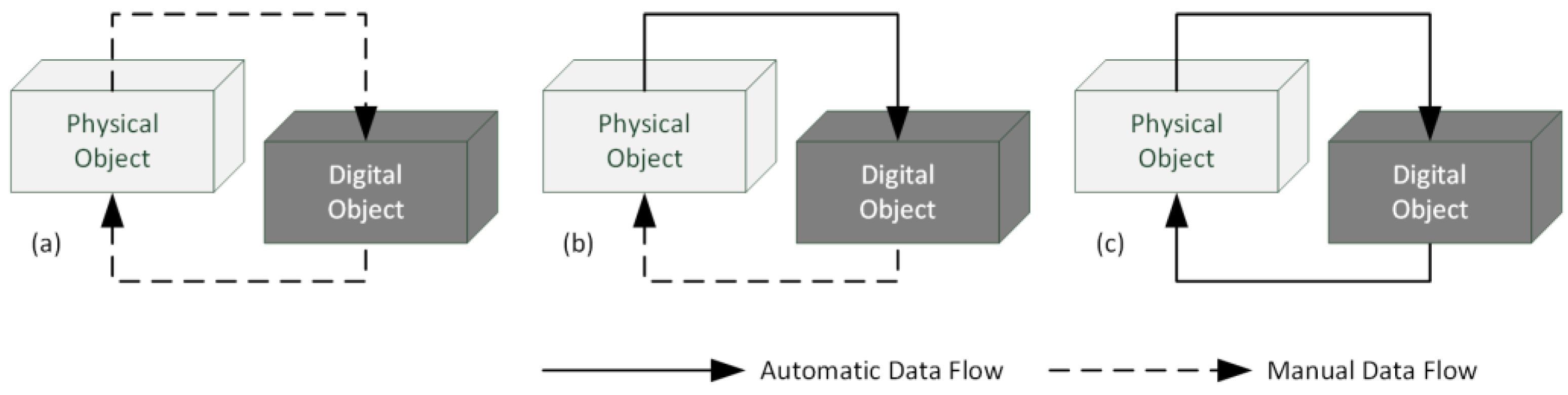
Figure 2.
Conceptual process chain for the software-defined value stream process systems (SVPS). The features of a product are planned digitally, and the machine configuration is optimized to produce these features. Specialized digital twins bridge the gap between product features and machine capabilities.
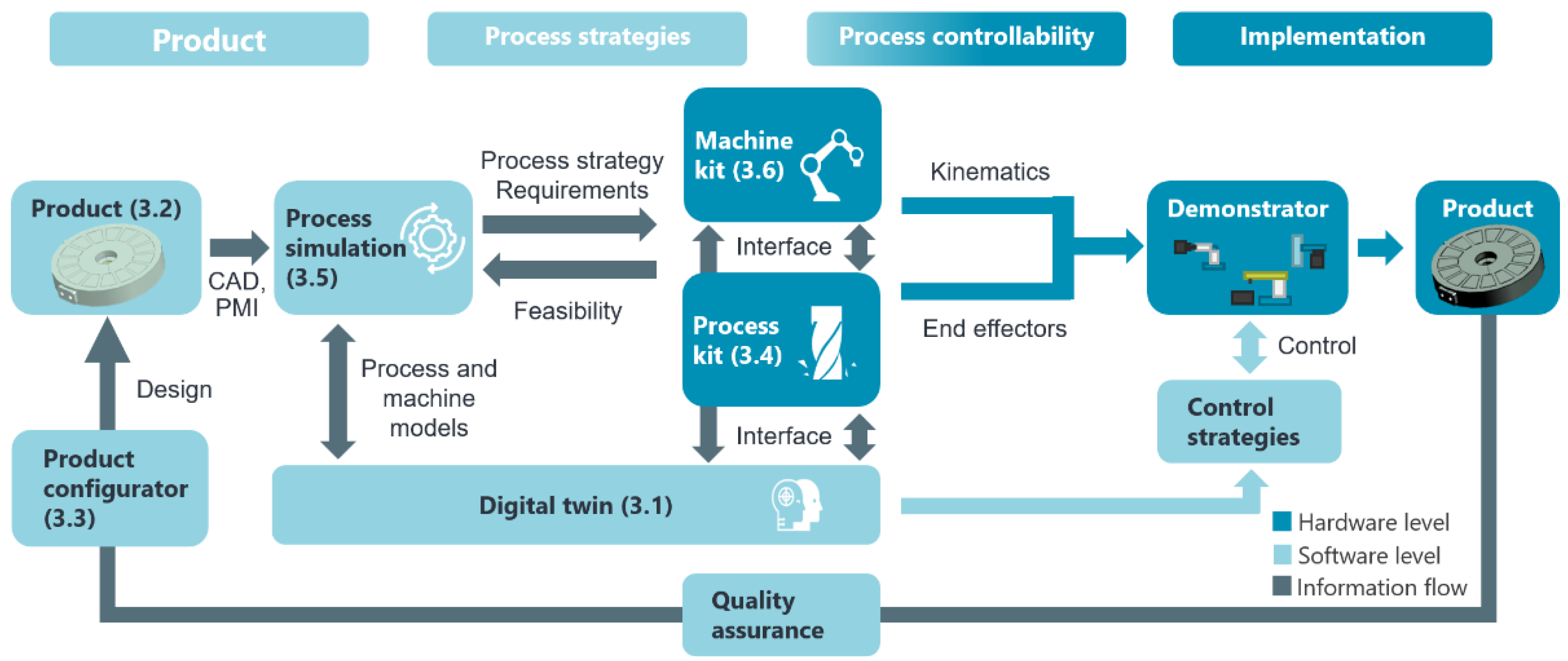
Figure 3.
Structure of the digital twin.
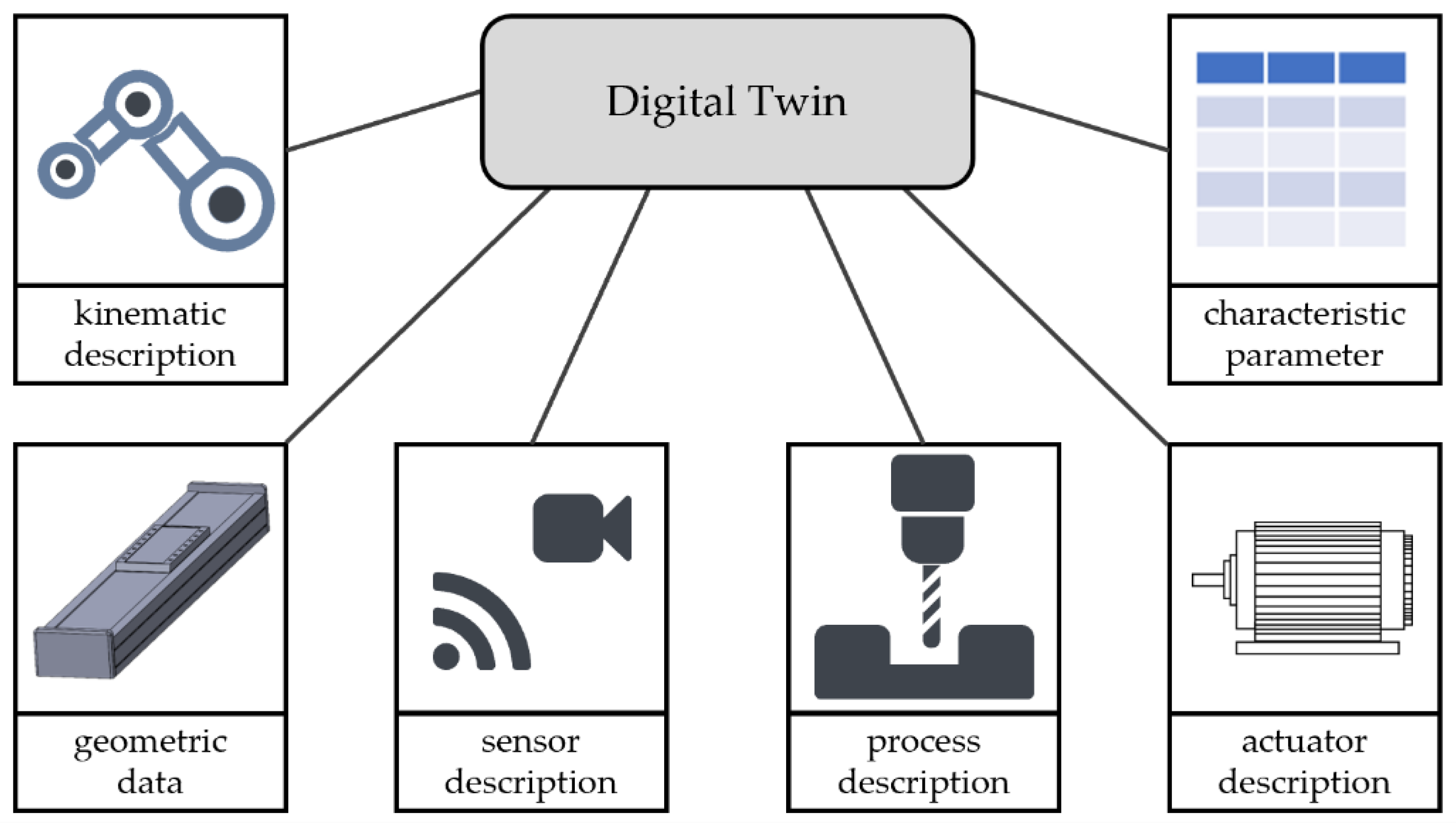
Figure 4.
Modules of an exemplary axial flux machine.
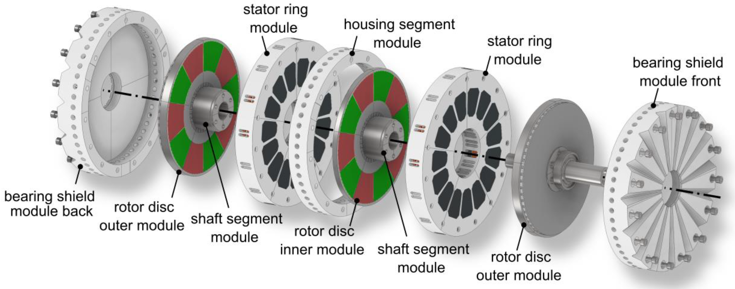
Figure 5.
Product configurator to model the product and effectively illustrate the interactions between design requirements and their implementation in production.
Figure 5.
Product configurator to model the product and effectively illustrate the interactions between design requirements and their implementation in production.
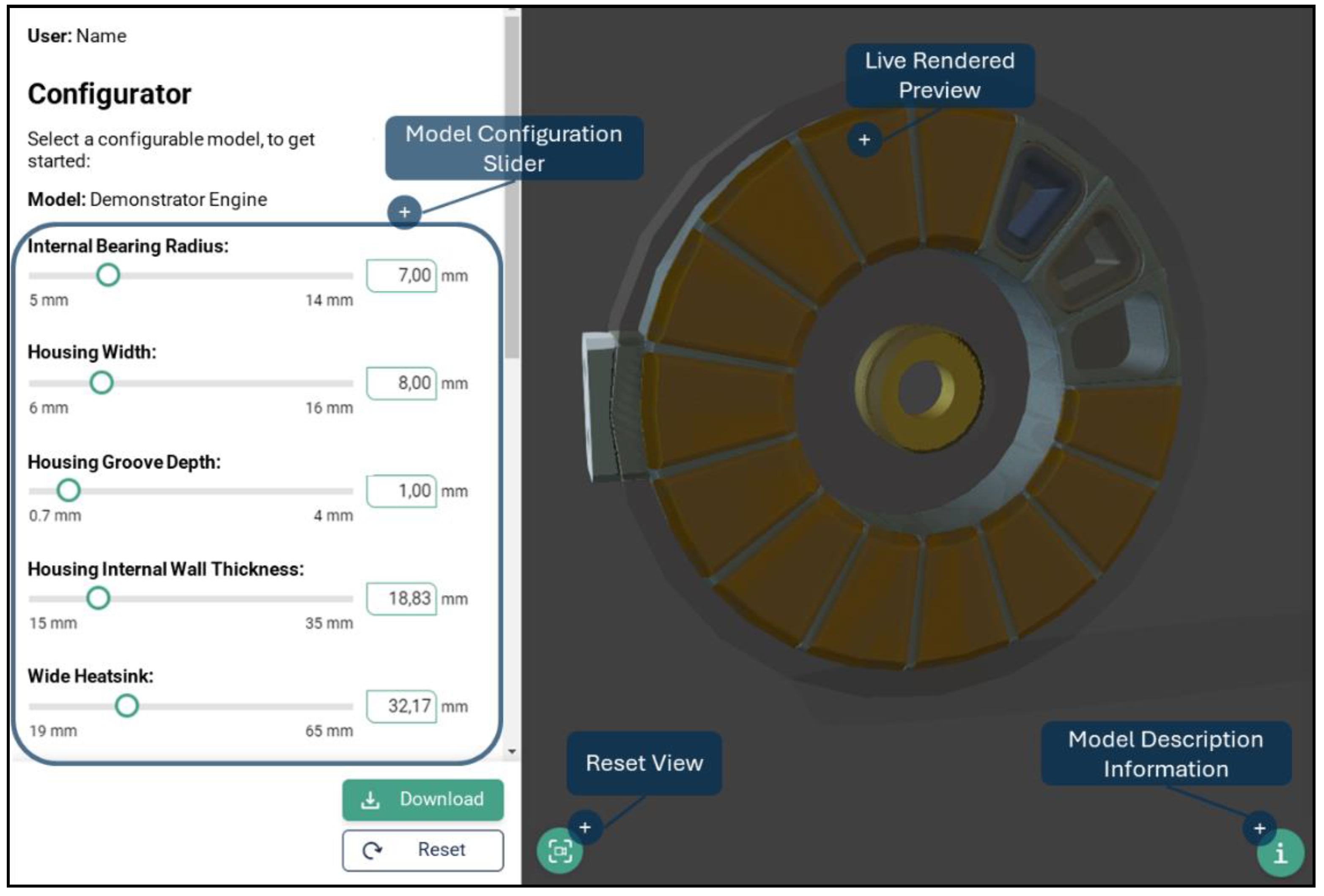
Figure 6.
Multisensory-multi-process end-effector for application to various kinematics according to [50].
Figure 6.
Multisensory-multi-process end-effector for application to various kinematics according to [50].
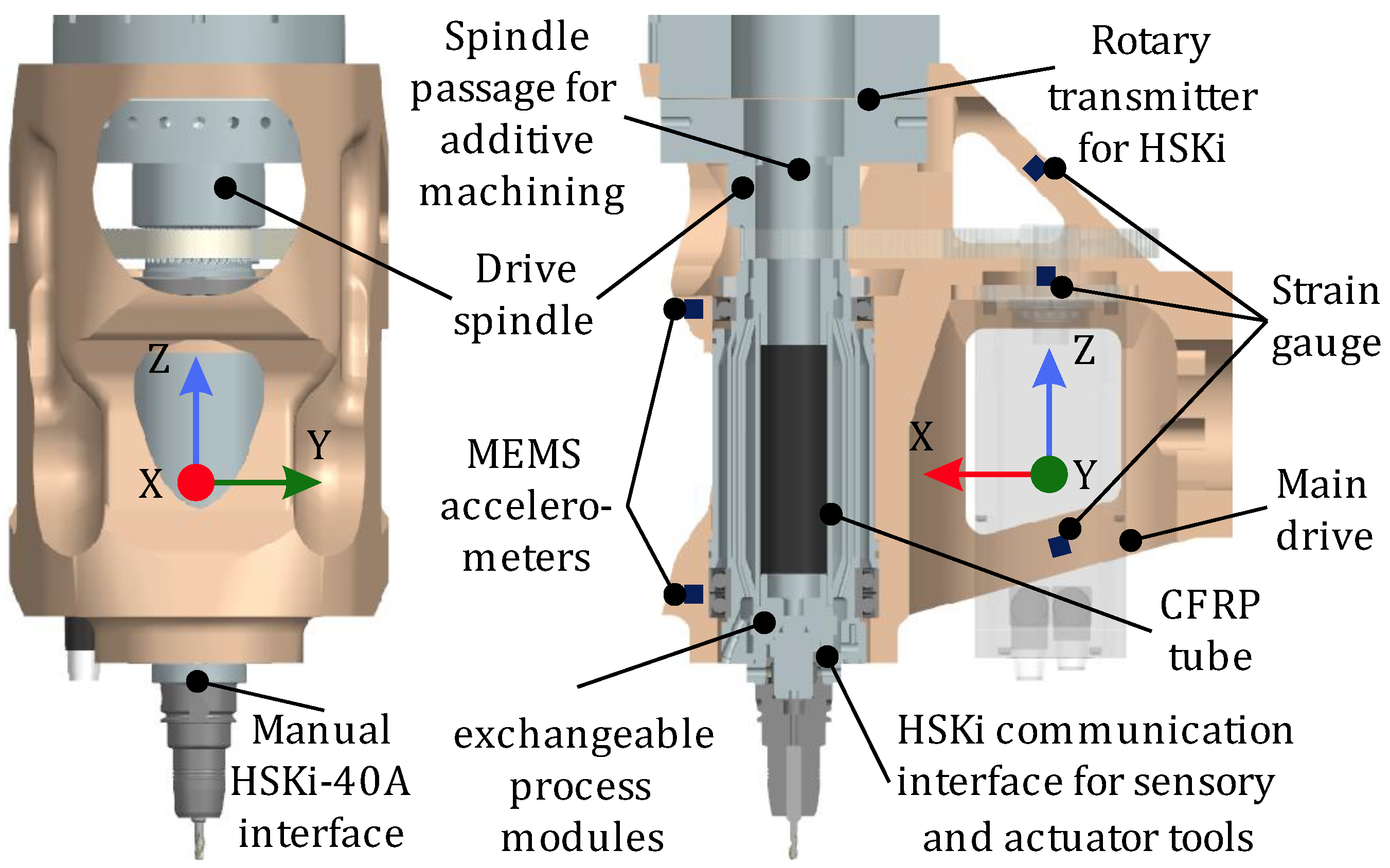
Figure 7.
Machine demonstrator setup for milling. Includes reconfigurable machine axes, interfaces between them, and storage to enable the production of processes requiring different machine configurations.
Figure 7.
Machine demonstrator setup for milling. Includes reconfigurable machine axes, interfaces between them, and storage to enable the production of processes requiring different machine configurations.
Disclaimer/Publisher’s Note: The statements, opinions and data contained in all publications are solely those of the individual author(s) and contributor(s) and not of MDPI and/or the editor(s). MDPI and/or the editor(s) disclaim responsibility for any injury to people or property resulting from any ideas, methods, instructions or products referred to in the content. |
© 2024 by the authors. Licensee MDPI, Basel, Switzerland. This article is an open access article distributed under the terms and conditions of the Creative Commons Attribution (CC BY) license (http://creativecommons.org/licenses/by/4.0/).
Copyright: This open access article is published under a Creative Commons CC BY 4.0 license, which permit the free download, distribution, and reuse, provided that the author and preprint are cited in any reuse.


