Submitted:
12 November 2024
Posted:
13 November 2024
You are already at the latest version
Abstract
The use of Very High Energy Electron (VHEE) beams, with energies between 50 and 400 MeV, has drawn considerable interest in radiotherapy due to their deep tissue penetration, sharp beam edges, and low sensitivity to tissue density. VHEE beams can be precisely steered with magnetic components, positioning VHEE therapy as a cost-effective option between photon and proton therapies. However, clinical implementation of VHEE Therapy (VHEET) requires advances in several areas: developing compact, stable, and efficient accelerators; creating sophisticated treatment planning software; and establishing clinically validated protocols. In addition, the perspective of VHEE to access ultra-high dose-rate regime presents a promising avenue to practical integration of FLASH radiotherapy of deep tumors and metastases with VHEET (FLASH-VHEET), enhancing normal tissue sparing while maintaining the inherent dosimetric advantages of VHEET. However, FLASH-VHEET systems require validation of time-dependent dose parameters, thus introducing additional technological challenges. Here we discuss recent progress in VHEET research, focusing on both conventional and FLASH modalities, and covering key aspects including dosimetric properties, radioprotection, accelerator technology, beam focusing, radiobiological effects, and clinical outcomes. Furthermore, we provide a comprehensive analysis of initial VHEET in silico studies on coverage across various tumor sites.
Keywords:
External beam radiotherapy
; VHEE
; FLASH radiotherapy
1. Introduction
Electron beams, with energies ranging from 5 to 20 MeV, are widely used in the RadioTherapy (RT) treatment of shallow tumour volumes [1,2]. However, due to their limited penetration ability, they are not suitable for deep-seated tumors (> 10 cm). Additionally, they exhibit significant lateral spread, especially at the depths of their practical range, and their air scattering is high enough to prohibit pencil beam scanning.
Around two decades ago [3,4,5] research suggested that by significantly increasing the energy of electrons, all the principal limitations of low-energy External Beam RT (EBRT) could be adequately addressed. In this context, the study of Very High Energy Electron (VHEE) beams, ranging from 50 to 400 MeV, opened the possibility of developing a new type of electron EBRT, termed VHEET, which could potentially treat deep-seated tumor sites. From an academic perspective, a key question arose from initial studies: is it worthwhile to pursue the clinical development of VHEET? Or does VHEET offer significant advantages over well-established X-rays RT? A stimulating discussion on these questions can be found in the 2004 point/counterpoint debate titled Are VHEE beams an attractive alternative to photon IMRT (Intensity-Modulated RT)? by Papiez and Bortfield [6], which first highlighted the pros and cons of VHEET. To the point, listed advantages included higher healthy tissue sparing potential than photons, reduced sensitivity to anatomical inhomogeneities, and ease of ElectroMagnetic (EM) scanning in pencil beam configuration. On the counterpoint, noted disadvantages were the relatively flat dose distribution with a high entrance dose and a significant yield of secondaries (mainly neutrons). Most of these issues have been addressed in subsequent studies.
From a chronological perspective, the rising interest in VHEET has paralleled the growing attention to the so-called FLASH effect [7]. Characterized by Ultra-High Dose-Rate (UHDR) irradiation of 40 Gy/s, FLASH is now considered one of the most promising breakthroughs in RT. Although the mechanism behind the FLASH effect remains unclear as of this writing, the benefits of FLASH-RT have been proved: at UHDR, normal tissue toxicity is reduced while anti-tumor efficacy is maintained. In this context, VHEE FLASH-RT could represent an exceptional treatment solution, as it would combine the normal tissue sparing capability of FLASH with the unique dosimetric advantages of VHEET. Therefore, the use of VHEE beams for FLASH-RT is highly anticipated in the near future, with numerous studies aimed at developing reliable clinical platforms.
Despite the highly attractive properties of VHEE beams for therapeutic use, their successful clinical implementation critically depends on academic research [8]. To this end, developing safe, stable, and compact VHEE beam delivery systems is crucial. At the actual status of research, VHEET acceleration systems primarily rely either on research-based RadioFrequency (RF) linear accelerators [9,10,11] or laser-driven [12,13,14,15] plasma accelerators. However, a more systematic investigation as well as major engineering and industrial efforts are required before compact and clinically compliant prototypes will emerge from these technologies. The development of VHEET delivery systems also calls for the advancement of fast and accurate VHEET treatment planning systems [16]. Moreover, the clinical translation of VHEET still necessitates the development of accurate and practical secondary dosimeters [17], as well as a deeper understanding of VHEE radiobiology [18].
This paper reviews the most recent developments in VHEET-related research and is organized as follows: Section 2 covers the physical properties of VHEE beams. Section 3 evaluates dose contributions from secondary neutrons and induced radioactivity. Section 4 discusses FLASH-VHEET under UHDR conditions. Section 5 examines advancements in VHEE RF linac-based and laser-driven accelerators. Section 6 highlights the benefits of beam focusing, while Section 7 addresses VHEE dosimetry. Section 8 reviews recent findings in VHEE radiobiology. Section 9 presents the current status of VHEE treatment planning systems and provides an overview of preliminary clinical assessment results across various tumor sites.
2. VHEE Beams Physical and Dosimetric Properties
This section evaluates the key properties of VHEE beams. The terms divergent and non-divergent/collimated beam will be used frequently throughout the paper, with definitions provided in Table Section 11.
2.1. Longitudinal Dose Distribution
The main properties of VHEE beams were first evaluated in the early 2000s by DesRosiers et al. [3], who highlighted their potential clinical advantages compared to photon RT. In general, the main longitudinal dosimetric parameters of an electron beam are: a) , the depth at which the maximum dose deposition occurs; b) PFO, the Proximal Fall-Off at 90% of ; and c) TR, the Therapeutic Range at 90% of . As shown in Figure 1a, for an ideal parallel beam with no divergence (i.e., collimated) and a transverse extent greater than the electron mean free path, the VHEE depth-dose curve presents three distinct regions: 1) a build-up region (surface to PFO), where the dose increases from its surface value toward 90% of , 2) a wide dose peak region (PFO to TR), where all dose values are above 90% of , and 3) a rapid fall-off region (beyond the TR), where the dose quickly decreases.
At depths greater than the maximum VHEE range, the tail of the depth-dose distribution is due to Bremm. photons. Ideally, the tumor should be located in the dose peak region, with both the build-up and fall-off regions kept as steep as possible to ensure effective sparing of the skin and the healthy tissues surrounding the tumor site. Bohlen et al. [19] systematically examined the dosimetric properties of VHEE beams. They found that, for a parallel beam, both the PFO and the TR increase with energy in a linear and non-linear fashion, respectively. For beams smaller than 10×10 cm2, both PFO and TR markedly increase with beam size. For beams larger than this value, the same trend is observed, but the growth with beam size is smoother. With a dose peak region potentially extending up to 40 cm (for a 250 MeV beam with a 15×15 cm2 beam size), it is evident that VHEE beams ensure solid and adequate penetration through the patient’s body. Figure 2a and b show the Percentage Depth Dose Distribution (PDD) in water (with vacuum beforehand) of ideal VHEE beams, ranging in energy from 50 to 400 MeV in steps of 50 MeV, for an entrance beam diameter of 1 and 10 cm, respectively.
Differently from low-energy electrons, the VHEE divergence due to scattering in air is quite negligible. However, a relatively extended Source to Surface Distance (SSD), may lead the beam to diverge. As observed by Bohlen et al., for a divergent (i.e., non collimated) VHEE beam, the PFO lies almost at the surface, causing the build-up region to shift within the peak region. In this situation, the TR values show almost no energy and beam size dependencies, resulting in smaller TR values compared to collimated setup, with the difference increasing with beam energy.
2.2. Transversal Dose Distribution
The transversal profile of an electron beam can be characterized by the Lateral Penumbra (LP), i.e., the distance between the 90% and 20% intensity levels, and the Beam Width (BW), i.e., the width at 90% of the maximum dose value at a given depth. Intensity levels are typically normalized to the maximum dose value. For a collimated 200 MeV VHEE beam in water, the LP and BW values are depicted in Figure 1b, Figure 1c, Figure 1d at a depth of , 20, and 30 cm, respectively. Generally, VHEE beams lateral penumbras increase with depth: for VHEE beams with energy higher than 100 MeV, this increase is very slow at shallow depths, as fast electrons experience less scattering. However, penumbras grow considerably as electrons propagate to greater depths. Lateral scattering, which is relatively higher further away from the central axis, causes a disparity between the on-axis and integrated PDDs, as also observed from the difference between the main plots and the inset plots in Figure 2. This disparity is more pronounced in VHEE beams compared to photons and protons, nonetheless, all significant PDDs properties, shape and peak position, remain unaltered.
Beam broadening at any given depth significantly decreases with increasing beam energy and only slightly decreases with decreasing beam sizes. In comparison to photon beams, VHEE beam penumbras are relatively narrower at depths less than 5 cm and relatively wider at depths greater than 10 cm. However, since the photon PDD decreases more rapidly, the central axis dose is lower for photon than for VHEE beams at greater depths. In other words, in absolute terms, there is more spread in photon beams than in VHEE beams, which is not fully reflected by the values of relatively normalized penumbras.
For collimated beams the BW significantly decreases with depth. Conversely, beam divergence leads to a proportional increase in the BW at the phantom entrance, thus broadening the beam. As depth increases, the BW widening from divergence is counteracted by the predominant amplitude of scattering [20]. Consequently, there is generally no beam size reduction with depth.
2.3. Surface Dose
For a collimated beam, the surface dose to ratio decreases with increasing beam energy and/or enlarging beam size. This reduction is due to the greater contribution of secondary electrons and the longer build-up region of higher energy VHEE beams. However, at its best, the surface dose only lowers to about 66% of for a 250 MeV beam energy and a 10×10 cm2 beam size. Conversely, the surface dose to ratio of a divergent VHEE beam ranges from 90 to 95%. In its current state, the surface-sparing potential of single VHEE beams is substantially lower than that of single-photon beams; indeed, the photon surface dose is equal to or even lower than 20% of . To circumvent this, the introduction of focusing systems along the VHEE beamline is being evaluated, as these systems could lower the entrance dose.
When multiple-beam arrangements are planned, the high VHEE entrance dose becomes less of a concern. In fact, the VHEE relative surface dose decreases to 60–80% with two parallel beams and to less than 50% with two perpendicular beams. Increasing the number of beams further reduces the surface dose. For example, the VHEE surface dose to ratio decreases to less than 30% when four beams are employed. Conversely, with two parallel opposed photon beams, the surface dose is more than doubled.
2.4. Insensitivity to Density Variations
Due to the lack of electronic disequilibrium, VHEE beams exhibit robustness against density variations and anatomical changes, making them a promising option for treating highly inhomogeneous tumors. The dosimetric effects of inhomogeneities on VHEE beam dose profiles were studied in-silico by Papiez et al. [21] and Zhou et al. [22], and by Lagzda et al. [23], both in-silico and experimentally. Papiez et al. modeled a 200 MeV VHEE beam and compared it with a 15 MV photon beam in a water phantom scenario. They introduced a 2 cm spherical air cavity positioned tangentially to the beam path at a depth of 10 cm. At the edge of the cavity, a 50% decrease in dose was observed for the photon beam, whereas no significant dose variation was seen for the VHEE beam. The study by Lagzda et al. involved delivering a 156 MeV VHEE beam onto a water phantom containing slabs inserted at a depth of 2 cm. Various slab materials were chosen to simulate the dosimetric properties of soft tissue, water, and cortical bone, covering a density range from 0.001 - 2.2 g/cm3. For each slab material, simulations compared the dose profiles of VHEE beams with those of therapeutic photons and protons under the same conditions of material heterogeneity. The results indicated that, for all embedded materials, the on-axis dose variation of VHEE beams was below 5–8%. In comparison, photon and proton dose variations were found to be as high as 74 and 100%, respectively. Lastly, using GATE Monte Carlo (MC) toolkit, Zhou et al. evaluated the influence of inhomogeneities on 200 MeV VHEE beams, either focused or just collimated, 6 MV CyberKnife beams, and 150 MeV proton beams. A spherical air or rib-bone insert was embedded within a water phantom before the dose peak, along or slightly below the beam axis. Compared to photon and proton beams, VHEE beams, especially the focused ones, showed almost no dosimetric impact. Conversely, an extended dose under- and over-shoot was observed for photon and proton beams when rib and air inserts, respectively, were placed in the two positions.
2.5. Electromagnetic Scanning
VHEE can be easily manipulated by magnetic components. The charge-to-mass ratio of electrons is 1836 times higher than that of protons [24], resulting in a magnetic rigidity that is lower by a factor of approximately 3–4 compared to protons of similar energy [8,25]. This means that, relative to protons, electrons can be steered and accelerated with a substantially lower intensity magnetic field, leading to a smaller technological footprint. By applying EM scanning, VHEE beams could be precisely steered along both the transverse and perpendicular planes, facilitating advanced control over beam delivery, including Intensity-Modulated VHEE Therapy (IM-VHEET).
Because of their magnetic rigidity, electrons are highly susceptible to the Lorentz force in a Magnetic Resonance (MR) field, making MR-guided VHEE RT particularly challenging. Nevertheless, Yang et al. [26] proposed a potential solution, MR-PVHEE, which comprises a steering device and an MR imaging device. Using TOPAS simulations, the authors demonstrated that the steering device, i.e. a triple-stage electromagnetic steering coil set, can successfully prevent VHEE beam trajectory twisting and deflection due to the MR field.
3. Radiation Protection in VHEE Radiotherapy
3.1. Secondary Radiation Produced by the VHEE Beam in the Patient
3.1.1. Neutrons
From a radiobiological perspective, neutron emission is of particular concern due to its high Linear Energy Transfer (LET) and Relative Biological Effectiveness (RBE), which lead to significant radiation damage. In the VHEE energy region, neutrons are primarily produced through nuclear fission initiated by Bremsstrahlung (Bremm.) photons. The Bremm. photon fluence decreases monotonically with energy, forming a broad spectrum that extends to the maximum value, the Bremm. endpoint. The Bremm. photons angular distribution is sharp, with the main emission along the beam direction. Regarding neutron production and considering the Bremm. spectrum, two key energy regions can be identified. The first is the region of Giant Dipole Resonance (GDR) (E<50 MeV). The second, more relevant for high-Z materials, is the region of photon energies higher than that of the GDR.
- The giant dipole resonance (GDR) [27] occurs at photon energies equal to the (,n) reaction threshold: 10 to 19 MeV for low-Z nuclei (up to Z = 20, such as H, C, N, and O), and 4 to 6 MeV for high-Z nuclei (above Z = 20, such as Ca). During this process, the photon interacts with the nucleus as a whole, followed by the evaporation of neutrons from the excited nucleus.
- Above the GDR energy range, photons interact with nuclear clusters, initiating a nuclei-nuclei shower within the nucleus before neutron evaporation occurs. During this shower, parts of the nucleus gain energies that exceed the nuclear potential and are subsequently expelled.
The main channels of neutron production are the (,n), (,p), (,2n), and (,pn) reactions, with the (,2n) and (,pn) reactions being one order of magnitude less frequent than the (,n) reaction. The GDR can be assumed to yield neutrons exclusively. The angular distribution of GDR-produced neutrons is isotropic, with a Maxwellian energy distribution. In materials of interest for RT, considering both photon energy regions, the overall neutron distribution is nearly isotropic. The neutron yield increases as the upper limit of the Bremm. spectrum increases. The neutron spectrum averages at about few MeV, reaches a maximum in the low-energy region, and rapidly decreases with increasing energy. The neutron quality factor for RBE estimation is conservatively taken as 10 [28].
Using Swanson theory of (,n) cascade [29], DesRosiers et al. [3] estimated the neutron fluence to be 0.027 and 0.037 neutrons per incident electron (n/e) for VHEE beams of 150 and 200 MeV, respectively. These values are several orders of magnitude higher than those reported in recent studies. Using FLUKA MC code, Subiel et al. [30], reported an order of 10−5 n/e for a 165 MeV VHEE beam, while Kokurewicz et al. [31] predicted an order of 10−4 n/e for a 200 MeV VHEE beam. Considering an SSD of 100 and 5 cm, using TOPAS MC simulations, Masilela et al. [32] estimated a n/e yield of 7·10−8 and 2·10−7 for a 200 MeV beam at 0 and 30 cm depth within a water phantom. These authors further evaluated the difference in n/e values based on the various Geant4/TOPAS physics list employed in the simulation, with good agreement between the BERT, BIC, and INCLXX models.
According to DesRosiers et al., a VHEE beam with 2·109 electrons (2 Gy at ) results in a neutron flux of 5.5·107 (150 MeV) and 7.3·107 (200 MeV) per cm2, leading to a 0.2% dose increase due to neutrons fluence at d. Conversely, Kokurewicz et al. reported about 105 neutrons on a 2 Gy fraction at the target. By means of comparison, Howell et al. [33] estimated the neutron fluence due to the secondary neutron emission for a low-energy clinical electron beam (Varian 21 EX linac, 20 MV nominal energy, 10×10 cm2 beam). A fluence of 1.69·105 neutrons (cm2 MU−1) was reported at . In general, all findings agreed that neutron contamination has a negligible effect on dose deposition.
3.1.2. Radioactive Isotopes
Induced radioactivity is also caused by reactions initiated by Bremm. photons. Based on the Cember theory [34], DesRosiers et al. [3] theoretically estimated a 0.01% dose increment from induced O, C, and N radioactivity when using a 150 MeV VHEE beam. Using FLUKA MC code, Subiel et al. [30] reported an averaged equivalent dose-rate of 96 and 3 pSv s−1 at the front wall of a water phantom, and 458 and 38 pSv s−1 at the rear phantom wall, at one and 20 minutes post-irradiation time, respectively. The 165 MeV VHEE beam activity was attributed to 11C (=22.3 min) and 15O (=122.4 s) at one minute, and 11C only at 20 minutes. Due to the higher Bremm. production, dose-rate values increased with depth. Kokurewicz et al. [35] assessed activation from VHEE interaction with dense body materials such as bone and skeletal muscle, identifying isotopes like 10C, 11Be, 14N, and 23Ne. Assuming a dose-rate of 2 Gy s−1 at the target, the total activity for a 200 MeV VHEE beam was 240 Bq at one minute and 5 Bq at 20 minutes post-irradiation. The equivalent dose due to induced radioactivity was found to be insignificant and, at post-irradiation times of about 10 minutes, even lower than the natural background (∼100 pSv s−1).
3.2. Ambient Dose in VHEET Treatment Rooms
Masilela et al. [32] investigated the ambient dose outside a water phantom within a modeled treatment room surrounded by semi-infinite concrete walls. The neutron yield in ambient air decreased with distance from the water phantom but increased in proximity to the walls due to interactions occurring there. The highest ambient dose was estimated to be ∼0.17 mSv/Gy, which is comparable to that of proton therapy treatments [36]. In conclusion, no additional shielding is envisaged for future VHEET treatment rooms.
4. VHEE FLASH Radiotherapy
FLASH-RT traces back to the 1970s, when significant normal tissue protection was first observed after exposure to FLASH-RT [37,38]. This effect was later confirmed in the 1980s with reduced toxicity in mice irradiated with low-energy electrons [39]. After a three-decade gap, Favaudon et al. [40] re-discovered the FLASH phenomenon. Since then, FLASH-RT has emerged as a highly promising modality [41], with standard RT now often referred to as CONVentional (CONV) for comparison. At its core, FLASH-RT involves the delivery of radiation dose at Ultra-High Dose-Rates (UHDR). Generally, FLASH-RT mean dose-rate is ≥ 40 Gy/s, with an optimal rate around 100 Gy/s [42], whereas CONV dose-rate is ≥ 0.01 Gy/s. However, the full FLASH effect is more complex and also depends on other interdependent temporal parameters [43]. Ideally, to elicit the FLASH effect: 1) the beam should be pulsed at a frequency of about 100 Hz, 2) the dose-per-pulse should be ≥ 1 Gy, 3) the dose-rate within the pulse should be ≥ than 106 Gy/s [44]. Together, these parameters should provide a total FLASH-RT delivery time ranging from microseconds to hundred of milliseconds, where a CONV-RT treatment typically requires several minutes [45]. To clarify, Figure 3 schematically depicts the inter-dependent temporal parameters characterizing an entire RT treatment, a single RT fraction, and a single pulse, for both the CONV and FLASH-RT modalities.
Despite numerous ongoing studies [46], the mechanisms behind FLASH-RT remain unclear. Various hypotheses have been suggested [47,48,49,50], and it is likely that all these mechanisms contribute to the FLASH effect to varying extents [51]. Compared to CONV modalities, the rationale for FLASH-RT lies in its ability to offer relative protection to normal tissue while preserving the anti-tumor efficacy of CONV-RT. Clinically, leveraging the FLASH effect is promising for radio-resistant tumors, enabling higher dose escalation without severely harming surrounding tissues. Moreover, FLASH-RT could serve as an alternative when CONV-RT delivers effective tumor doses but results in significant normal tissue damage [44].
A major challenge in translating FLASH-RT to the clinic is developing optimal technological systems capable of delivering FLASH-RT. Low-energy electrons were the first type of radiation whose feasibility at UHDR was assessed under pre-clinical and clinical conditions. The Kinetron (CGR-MeV, Paris, France) [52,53] and Oriatron eRT6 [45,54] (PMB, Peynier, France) experimental electron linacs, developed at Orsay and Lausanne University Hospital, respectively, are the most notable FLASH delivery systems. These systems offer FLASH irradiation with energy ranges of 4-5 and 4.9-6 MeV, respectively, featuring millisecond macro pulses and an intra-pulse dose-rate of 106 Gy/s. In 2019, the Oriatron eRT6 was used to perform the first FLASH-RT treatment on a patient with cutaneous lymphoma [55].
Several efforts have been made to tune existing clinical linacs for low-energy electron FLASH-RT experiments. A scheme to achieve a mean dose-rate between 30-300 Gy/s and of 74 Gy/s was demonstrated on an Elekta Precise linac [56] and Varian Clinac 21EX [57] and 23EX [58] linacs, respectively. Compared to the experimental ones, clinical linacs offer beam energies, 8 to 20 MeV in range. However, due to their geometrical and dosimetric properties, they are suitable only for small animal experiments.
The procedure for transforming an IORT linac into a FLASH machine was also evaluated, with investigations performed by the same group on the NOVAC C7 (3, 5, 7, 9 MeV) [59] and Mobetron (6 MeV) [60] systems. Based on this experience, in collaboration with the SIT company [61], ElectronFLASH was designed; a compact S-band standing wave linac, operating in FLASH modality at 5 and 7 MeV [62,63].
Research accelerators such as the Electron Linear Accelerator for Beams of High Brilliance and Low Emittance (ELBE) at HZDR in Dresden, Germany [64,65], and the Advanced Rare Isotope Laboratory (ARIEL) at TRIUMF in Vancouver, Canada [66], which deliver pulsed electron beams with energies up to 40 and 30 MeV, respectively, may also provide access to ultra-high pulse dose-rates suitable for FLASH-RT.
VHEE FLASH-RT represents a unique treatment solution, as it combines the normal tissue sparing capability of FLASH with the unique dosimetric advantages of VHEET. From a technological standpoint, the development of FLASH-RT VHEE systems, like the development of RT VHEE systems at CONV dose-rates, is currently limited to a few research infrastructures [67]. Recently, radiobiological assessments of VHEE beams at UHDR have been conducted [68,69], while novel dosimeter concepts capable of withstanding UHDR were introduced [17,70]. These studies are laying the groundwork for further investigations into VHEE FLASH-RT.
5. Accelerators for VHEE Beams
VHEE delivery systems fall into two main categories: 1) RF linear accelerators and 2) laser-plasma accelerators. Several RF linac-based facilities currently produce VHEE beams, supporting both CONV and FLASH studies. However, these large academic setups lack delivery control features like rotating gantries and EM steering [43]. To address this, more compact RF linac platforms for FLASH-RT are also being developed. Laser-plasma accelerators, with high-gradient energy boost, offer a compact alternative for VHEE generation. Their short bunch duration and high charge per pulse enable high peak dose rates, making them suitable for UHDR investigations. Figure 4 shows the global distribution of RF linac-based (green), laser-based (red), and RF linac-based compact FLASH-dedicated (yellow) VHEE accelerators. For a broader overview of laser systems, including those not involved in VHEET research, the reader is referred to [71].
5.1. RF Linacs VHEE Beams Accelerators
Figure 5 schematically depicts the bare-bone structure of an RF linac. The particle source, typically powered by a high voltage supply, generates charged particles and injects them into the beamline. A common electron source is a photon-electron gun. To prevent collisions between the accelerated electrons and air molecules, the source and all other beamline components are housed within a vacuum chamber. The length of the vacuum pipe containing the beamline can range from meters to thousands of meters, depending on the application. The electrons to be accelerated pass through a series of hollow cylindrical electrodes, which are progressively spaced farther apart as they move away from the source. This design ensures that the electrons pass through each electrode in half a cycle of the accelerating voltage. The open-ended cylindrical electrodes are powered by a microwave source, such as a klystron or magnetron, which generates an RF AC voltage on the order of thousands of volts. This setup applies opposite voltages to successive electrodes. The RF source can operate in various frequency bands, including L-band (1-2 GHz), S-band (2-4 GHz), C-band (4-8 GHz), or X-band (8-12 GHz). Low power accelerators typically use a single RF source, while high power machines comprise separate amplifiers, all synchronized by a frequency modulator. After passing through the final electrode, the electrons reach the beam diagnostic and manipulation area.
5.1.1. RF Linacs VHEE Beams Accelerators, Facilities Overview
RF linac-based facilities capable of producing VHEE beams are listed below. The Compact C-band system and the PHASER platform occupy the final positions; these are novel, more compact, RF linac platforms specifically designed for FLASH-RT.
CLEAR (CERN, Switzerland)
Located in the former CLEX experimental area [72] at the CERN Meyrin site (Geneva, Switzerland), the CERN Linear Electron Accelerator for Research (CLEAR) [73] is a user facility generating stable 60–220 MeV quasi-monoenergetic VHEE beams with adaptable beam size, bunch charge, and energy. The CLEAR facility comprises the 25 m long CALIFES (Concept d’Accélérateur Linéaire pour Faisceau d’Electron Sonde) beamline, followed by a 16-meter beamline that can be modified to meet user requirements. The electron source consists of a Cs2Te photo-cathode pulsed by a UV laser. The beam is then accelerated along three S-band acceleration structures powered by two independent klystrons. CLEAR is equipped with a full set of diagnostics, allowing precise bunch length and beam energy measurements. The VHEE beam at CLEAR has a charge-per-pulse range from 10 pC to 75 nC. The pulse width ranges from 0.1 ps to 100 ns, spaced at a frequency between 0.833 and 10 Hz. Each pulse is further subdivided into up to ∼150 shorter bunches, with an rms length from 0.1 to 10 ps and a charge-per-pulse from 10 pC to 1.5 nC. The bunches have a repetition frequency of either 1.5 or 3 GHz [74]. In recent years, several studies were conducted at CLEAR to investigate VHEET in both CONV and FLASH regimens. These studies focused on: VHEE beams physical characterization [23], radiobiology [75], dosimetry via ionization chambers [76,77], newly developed silica optical fiber sensors [70], inorganic [17] and organic [78] scintillators, focusing [11,35], and mini-GRID RT [79].
NLCTA (SLAC, USA)
The Next Linear Collider Test Accelerator (NLCTA) at SLAC National Accelerator Laboratory (Stanford, CA, USA) is a test accelerator delivering VHEE beams with energies up to 165 MeV and bunch charges up to 200 pC [80,81]. The VHEE beam is generated from a UV photocathode illuminated by a laser pulse and accelerated though an S-band gun. The beam is than boosted by two X-band accelerating structures. Bazalova-Carter et al. [82] benchmarked their MC simulations with VHEE beams measurements at NLCTA. Subsequent studies [83,84] modeled VHEE beam emittance based on NLCTA tests.
PITZ & ARES (DESY, Germany)
Two electron linear accelerators at DESY (Hamburg, Germany) were used to study 1) UHDR low-energy electron therapy (PITZ) and 2) VHEET (ARES). At the Photo Injector Test Facility at DESY in Zeuthen, PITZ, [85,86] the beam is generated by a 1.5 cell L-band RF gun and a Cs2Te photocathode and is further accelerated by a booster cavity. The beam energy is currently limited to 22 MeV, but an upgrade up to 250 MeV is planned. Single bunch lengths are produced in the range 0.1 to 60 ps and are repeated with a frequency ranging from 100 kHz to 1 MHz. From a technical standpoint, the pulse width can be up to 1 ms, with pulses spaced at frequencies between 1 and 10 Hz (0.1 and 1 s). Each pulse is further sub-divided in 1 to 1000 bunches (for 1 MHz repetition rate), with duration from 10 ps to 150 ns, and repetition frequencies ranging from 100 kHz and 1 MHz (1 and 10 s). The beams charge per pulse spans from 0.1 (low dose case/single bunch) to 5000 pC (high dose case/1000 bunches-per-pulse). Reaching a dose-rate per pulse of 4·1013 Gy/s in the high dose setup, the PITZ facility has demonstrated excellent potential for FLASH investigations [87]. The Accelerator Research Experiment at DESY in SINBAD (Short INnovative Bunches and Accelerators at DESY), ARES [88], is capable of producing VHEE beams with energies up to 155 MeV. After being generated with an RF photoinjector, the beam is accelerated by two S-band accelerating structures. The ARES charge per bunch ranges from 0.01 to 200 pC, with a repetition rate spanning from 1 to 50 Hz, and a pulse length ranging from 30 fs to 1 ps. Recently, the ARES beamline was used for VHEE radiobiology investigations [18].
SPARC (INFN-LNF, Italy)
Located at the INFN-LNF (Frascati, Italy), the Sources for Plasma Accelerators and Radiation Compton with Laser And Beam, SPARC, can produce VHEE beams up to 170 MeV in energy [89]. The SPARC photoinjector consists of a 1.6 cell RF gun with a Cu photocathode, generating a 6 MeV beam. A 1.6-cell RF gun includes one full RF cavity cell and an additional partial cell, which helps in optimizing the acceleration and phase stability of the emitted electron beam. The beam is then accelerated by three S-band accelerating sections. The SPARC beamline was emplyed for VHEE dosimetric assessments [30].
PRAE (Paris-Sud University, France)
The Platform for Research and Applications with Electrons (PRAE) [90], located at Orsay campus of Paris-Sud University, features an electron RF linac accelerator. The beam, up to 70 MeV in energy, is initially generated by a photo-injector that includes a normal-conducting RF gun, a drive laser, and two focusing solenoids. It is then further accelerated by an S-band accelerating structure. A second accelerating structure, expected to be added in the near future, aims to increase the beam energy up to 140 MeV. The PRAE beamline has been considered for UHDR mini-GRID VHEET [91].
The Compact C-Band System (Sapienza University/INFN-LNF, Italy)
A collaboration led by the Sapienza University of Rome and the Italian Institute for Nuclear Physics of Frascati (INFN-LNF), has proposed the design of a novel VHEE machine for FLASH-RT [9]. The system is based on an injector, operating at a frequency of 5.712 GHz capable of accelerating a CD gun pulsed current up to 200 mA at an energy of 10 MeV. The electron beam is then accelerated by four C-band linear travelling wave accelerating structures with a high accelerating gradient (> 40 MeV/m). Using four 90 cm long structures, the beam reaches the final energy of 130 MeV. Compared to the S-band accelerators typically used in research RF linac, the C-band technology ensures good particle transmission efficiency even at larger currents, with the added advantage of compactness. Furthermore, an upgrade to 160 MeV is envisaged if RF power amplification, through pulse compressors, is implemented. In this scenario, only three accelerating structures would be needed, keeping the whole system within a total length of 4 m. MC FLUKA simulations reported a delivered pulse dose-rate much greater than 106 Gy/s and a dose per pulse up to 200 Gy at buildup. Once commissioned and fully functional the system will be suitable for pre-clinical and radiobiological FLASH-VHEET investigations.
The PHASER Platform (SLAC, USA)
The Pluridirectional High-energy Agile Scanning Electronic Radiotherapy (PHASER) platform [10] (Stanford University) is a compact system under development at for FLASH IMRT. The PHASER project comprises 16 RF power sources with a large duty factor (330 kW peak RF power at 60 kV). The outputs of all RF sources are summed up via an RF phased-array power distribution network. The resulting 5.3 MW peak is directed to one of the 16 DRAGON (Distributed RF-coupling Architecture with Genetically Optimized call desigN) stationary non-coplanar beamline, with very high accelerating gradients (above 100 MeV/m). With fast-switching (300 ns) beamlines, the system eliminates the need for gantry rotation and meets the required time (< 500 ms) for FLASH-RT. It also removes the need for a multileaf collimator, achieving IMRT capability through either pencil-beam scanning or photocathode-derived spatially fractionated source images, accelerated in unison. The foreseen PHASER upgrade will involve the production of 100-200 MeV VHEE beams at UHDR. The shift from X-ray to VHEE is envisaged to be straightforward, requiring a higher RF power but a shorter pulse length.
5.2. Laser-Driven VHEE Beams Accelerators
Following the seminal work by Tajima and Dawson [92], the development of laser-plasma accelerators began in the early 1980s. This field, however, experienced a significant boost in the 1990s with the increasing availability of ultrashort and ultraintense lasers, which enabled access to the regime of Laser WakeField Acceleration (LWFA). As schematically depicted in Figure 6, the initial physical process of a laser-plasma VHEE accelerator involves focusing an ultra-short, ultra-intense laser pulse into a suitable target. The target, a gas-jet produced by a gas cell or a supersonic nozzle, forms an “underdense" plasma (i.e., transparent to the laser radiation) upon interaction with the laser pulse, through which the laser propagates. Due to the mass difference between ions and electrons, this force induces a strong, localized, charge separation. When “quasi-resonant" conditions are met, this separation results in a density perturbation that travels in the wake of the laser pulse. The resulting longitudinal EM field is named WakeField and propagates in the plasma at a velocity close to c. Due to the longitudinal nature of the electric field (i.e., parallel to the wave propagation direction), electrons can become “trapped" in the accelerating phase of the field and then boosted to relativistic speeds.
Given that the accelerating field in a plasma wave is up to 3-4 times larger than the corresponding field in a RF linac cavity, the most striking feature of LWFA is its ability to accelerate relativistic energy beams over very short distances. For instance, VHEE beams can be obtained with accelerating structures (i.e., plasmas) on the order of (sub)millimeters. The laser pulse, WakeField, and accelerated electron bunch are depicted in Figure 7 (produced by the authors using Particle-In-Cell simulations [93]).
In order to be effectively accelerated by the WakeField, electrons need a sufficient initial energy. LWFA techniques vary in how electrons are injected and trapped within the accelerating region of the traveling electric field. The choice of the injection technique is crucial, as it impacts the beam quality in terms of energy distribution, charge, divergence and, ultimately, emittance. LWFA injection techniques can be external or internal, usually referred to as self-injection. In external injection electron beams from an external source are injected into the plasma, with the timing of the injection triggering the trapping of the external electrons into the wave. In self-injection the accelerated electrons originate from the same plasma supporting the WakeField. Self-injection, in turn, can be further sub-categorized, as various techniques have been developed over the past few years. These techniques primarily aim to reduce the volume of the phase-space of the electrons injected into the wake; in this way, the final quality of the resulting accelerated beam can be improved. Primary methods of internal injection include bubble, ionization, and downramp or shock injection. A detailed description of all these techniques is beyond the scope of this review, and the reader is referred to [94].
In the context of RT applications the main features of LWFA-driven VHEE accelerators have been discussed in details [13,95] and are summarized below:
- Beam pulse duration: LWFA electron bunches feature a duration inherently in the few fs up to the ps range; this can be even several orders of magnitude shorter than that of medical RF accelerators (s), while a similar pulse duration can be obtained by advanced research type RF accelerators. Since the charge per pulse is comparable, this results in a much higher peak dose-rate in the LWFA compared to medical RF linac bunches, enabling UHDR investigations [96].
- System compactness: Unlike RF cavities, plasma can sustain extremely high electron fields, up to 100 GV/m or more for plasma electron densities of ne = 1019 cm−3 [97]. In comparison, the electric field in RF cavities are typically around 10-100 MV/m. Therefore, LWFA can boost electron energy over much smaller distances, making compact clinical installations possible [96].
- Beam steering: The VHEE beam direction follows mostly the laser propagation axis, which allows for active scanning techniques to be implemented by moving the final focusing optics and the gas target [12].
- System safety: No overall shielding of the accelerator system is needed, as the laser propagates from the laser facility up to the gas-jet target. Shielding is required only for the small section housing the accelerating structure [12].
Conversely, several issues with LWFA-driven VHEE accelerators still need to be addressed.
- Repetition rate: The current repetition rate of LWFA-driven VHEE accelerators is limited by the low repetition rate of high-power lasers (typically of 10 Hz), which restricts the mean dose-rate and/or the beam size. Indeed, mean dose-rates of Gy/min have been reported in recent literature [100]. Laser systems with repetition rates of 100 Hz and above are highly desirable, as they are expected to increase the mean dose-rate by 1-2 orders of magnitude [101]. Driven by research infrastructure developments [102,103], such systems are emerging at an industrial level and are likely to become operational in a few years.
- Stability: A critical feature hindering the forthcoming clinical use of LWFA VHEE beams is their poor stability, characterized by shot-to-shot fluctuations of bunch parameters, mainly energy, charge, and beam pointing [104]. Recently, major progress has been made in this field introducing correlation studies of parameters influencing the electron beam stability [105,106]. Similar to mean dose-rate, beam stability could be enhanced by high repetition rate lasers [107] introducing active feedback control loops. Furthermore, positive results in reducing beam pointing fluctuations have been obtained using a magnetic beam control system [14,108].
- Beam energy: Unlike RF linac-based VHEE beams, LWFA-beams produced using the injection mechanisms, are characterized by a broad to moderate electron energy spectrum, with the low-energy end (below 40 MeV) typically eliminated by the beam transport system [14,108]. This issue can affect beam focusing and must be accounted for in dosimetric considerations.
5.2.1. VHEE Laser-Driven Accelerators: Studies Overview
The use of laser-plasma accelerators for RT applications was firstly envisaged by Glinec et al. [12] and later theorized by Malka et al. [96]. In their study, Glinec et al., investigated the dosimetric aspects of a VHEE laser-accelerated electron beam. The beam was generated at the Laboratoire d’Optique Appliquée, LOA (CNRS/École Polytechnique/l’ENSTA-Paris). The beam specifications obtained were then imported into Geant4 MC simulations to model its propagation in a water phantom, assuming a 10 mrad FWHM divergence. No air scattering was considered and the beam was propagated in vacuum up to the phantom. The modeled dose distribution in water was considered of relevance for RT applications. Due to the quasi-monoenergetic nature of the beam, with a 170 MeV peak and 40 MeV FWHM energy spread, the shape of the dose distribution in the first 10 cm of the water phantom was found to be strongly dependent on the initial electron distribution. This effect, however, diminishes at greater depths where scattering dominates. Fuchs et al. [20] and Lundh et al. [97] continued the work of Glinec et al. at LOA. In the experiment conducted by Semushin and Malka [109], which served as the basis for the study by Fuchs et al., laser-driven beams were generated with peak energies from 60 to 250 MeV. In the study by Fuchs et al., beams with peak energies of 150, 185, and 250 MeV, and corresponding E/E energy spreads of 11.5, 8, and 6.5%, respectively, were imported into Geant4 to investigate the influence of laser-driven characteristics, primarily beam energy, energy spread, and angular spread, on dose distribution. Furthermore, using the same MC toolkit, a prostate IM-VHEET treatment was simulated, considering the beams with energies of 150 and 250 MeV. In the work by Lundh et al., a quasi-monoenergetic laser pulse was generated at LOA via external injected LWFA: 120 MeV peak with 20 MeV energy spread. Simulated and measured dose depth distributions, the latter obtained using the Geant4 MC toolkit, were compared within a water phantom. VHEE beams longitudinal profiles were found to be suitable for efficiently covering deep-seated targets.
Subiel et al. [30] assessed the response of radiochromic films, a common secondary dosimeter, to laser-driven VHEE beams. Films irradiation was performed at the ALPHA-X accelerator within the Terehertz to Optical Pulse Source (TOPS) facility (University of Strathclyde, UK) [110], using a VHEE beam spectrum of 135±44 MeV (rms).
More than a decade later, Kim et al. [111], at the Korea Electrotechnology Research Institute (KERI), evaluated the dosimetric and physical property of VHEE beams. The beam spectrum peaked at 94 MeV with an 80 MeV . Labate et al. [15] demonstrated that complex anatomical scenarios could be successfully irradiated using LWFA VHEE beams, utilizing stereotactic treatments and intensity modulation techniques similar to those characterising photon IMRT. This study was carried out using the 220 TW laser beamline at the Intense Laser Irradiation Laboratory (ILIL) at CNR, INO (Pisa, Italy) [112]. The beam spectrum ranged approximately from 50 to 250 MeV, with a relatively flat profile above 100 MeV.
Svendsen et al. [14], Lund High-Power Laser Facility (Lund, Sweden), and Guo et al. [108], Tsinghua University (Beijing, China), demonstrated that magnetic beam control leads to a reduction in beam dimensions and beam pointing instability. For example, according to Svendsen et al., when quadrupoles are in place, the beam pointing instability is reduced by an order of magnitude, while the beam spatial profile decreases threefold along the horizontal axis and twofold along the vertical axis. In these studies the very broad beam spectrum spanned from 0 to 150 [14] / 175 MeV [108], with a peak at 95 MeV in [14], and a flat distribution in [108]. Additionally, Glinec et al., Svendsen et al., and Guo et al., demonstrated that by combining LWFA with a magnetic control system, a deeply penetrating VHEE beam can be generated, yielding excellent 3D dose distributions. As will be described in Section 6.2, all these authors consider a magnetic system, comprising three magnetic quadrupoles, for VHEE beam focusing. On the other hand, Zhou et al. [22], (same group of Guo et al.), presented a new focusing system, based on two magnetic dipoles, specifically designed for LWFA beams.
Significant efforts are needed to transition LWFA structures from research platforms to treatment machines. Guo et al. [108] presented the first stable and compact LWFA treatment set-up, allowing the delivery of homogeneous dose distributions. The designed machine, about 2.8×1.4 m2 in size, could, potentially, be easily installed within a hospital-based therapy room. Stable operations were assessed on a prototype over 22 weekdays, with 2000-3000 shots per day, equating to tens of continuous running hours per day over a month. The prototype was used for radiobiological assessments, including mice irradiation, with the aim of comparing VHEET to photon RT.
LWFA VHEE systems in conjunction with a robotic arm represent another safe, compact, and efficient concept worth developing. In this regard, Nakajima et al. [113] presented the conceptual design of an LWFA-driven VHEET robotic system. Energy-amplified intense laser pulses are generated by a drive laser system and guided through a vacuum structure, the main robot body, to an accelerator chamber attached to the robot head. Within the accelerator chamber, laser pulses are focused onto the gas target, and the accelerated VHEE beam is then transported and delivered to the patient. Due to the six-degrees-of-freedom of the robotic arm, the target can be irradiated from multiple directions.
6. VHEE Beams Focusing
Beam focusing allows to concentrate dose deposition at deep locations, offering benefits such as 1) lowering entrance dose, 2) reducing lateral scattering in depth, and 3) precisely targeting small 3D volumes while sparing OARs and healthy tissue. Strong VHEE beam focusing is achieved using magnetic quadrupoles, each focusing the beam in one transverse plane and defocusing it in the other. The quadrupole’s magnetic field lines are shown in Figure 8, while Figure 9a, Figure 9b, and Figure 9c depict graphic rendering from the thin lens approximation and matrix formalism for focusing and defocusing quadrupoles and drifts, respectively. Final focus can be symmetrical (Figure 9d) or asymmetrical (Figure 9e), depending on whether the beam converges in one or both planes. A collimated beam, with only air scattering divergence accounted for, is considered non-focused. Terms like asymmetrically or line/symmetrically focused are defined in Table Section 11. Monochromatic VHEE beams from RF linacs allow uniform focusing using quadrupoles. In contrast, LWFA-produced VHEE beams have a broad energy spectrum, meaning only electrons with matching energy will be focused together.
6.1. Focusing Monochromatic VHEE Beams from RF Linacs
As reported in Section 2.3, a single parallel VHEE beam with no divergence yields a surface dose of at least 66% of . While multi-beam plans significantly reduce skin dose, the high entrance dose remains a limitation of VHEE beams. Single beam arrangements are important for accounting for tumor motion and could be crucial in FLASH-RT for reducing treatment times. Kokurewicz et al. [31] first observed that highly focused VHEE beams can concentrate dose peaks in small, well-defined volumetric elements (0.1-1 cm3), at selected target depths, achieving highly localized dose deposition while sparing adjacent tissues. Using FLUKA MC simulations, the effects of an ideal beam-focusing system were evaluated. A 200 MeV VHEE beam with Diameter (D) of 20 cm was modeled focused at a depth of 15 cm into a water phantom. The source-to-phantom distance, set at 9.1, 12.5, 16.7, 22.3, 30.1, 41.7, 61, and 99.3 cm, plus the focusing depth, yielded the Focal length (F), i.e., the source to focusing depth distance. As defined in optics, the f-number = F/D represents the focusing geometry; strongly focused beams were observed with an f-number ≤ 3.8 (F=61 cm), whereas non-focused, collimated beams correspond to f-number=∞. The shape of the volumetric element was found to be symmetrical with respect to the propagation axis for all f-numbers. At small f-numbers, the longitudinal and transverse dimensions of the volumetric element were comparable, the former being slightly higher, producing a nearly spherical volume shape. By increasing the f-numbers the spot size decreased and the longitudinal dimension of the volumetric element increased, yielding a more elliptical shape. For an f-number of 1.2 and 2.8, with respect to f-number=∞, the max surface dose was reduced by 40 and 211 times, respectively, and the total integral dose was decreased by 77.8 and 84.9%, respectively. For an f-number of 11.5, the peak dose at the surface was almost as high as the peak dose, whereas for an f-number of 1.2, it was more than 10 times lower. By shifting the source-to-phantom distance, the investigation was repeated to focus depths of 5 and 10 cm into the phantom; it was found that the peak dose decreases significantly with depth.
The first experimental analysis of focused VHEE beams was performed by Kokurewicz et al. [35]. Initially, the VHEE beam was expanded by using three magnetic quadrupoles, followed by focusing on another set of three quadrupoles. Due to technical constraints, only a line focus with a short focal length was achieved on the horizontal axis. For comparison, a symmetrical focus was examined using FLUKA MC simulations. Within a water phantom, the line focus was achieved at a depth of 14 cm for a 158 MeV VHEE beam (f/11.2), and at a depth of 10 cm for a 158 MeV VHEE beam (f/12.3) and a 210 MeV VHEE beam (f/18.2). Compared to a collimated VHEE beam, the line focus reduces the entrance dose. The symmetrical focus, on the other hand, shift the at deeper ranges within the phantom. This results in a more pronounced dose peak, with a significant reduction of the proximal and distal doses, providing a more favorable dose distribution. However, due to scattering, the peak dose is lower when symmetrical focusing is applied.
Whitmore et al. [114], conducted a MC TOPAS simulation study to compare the dose distributions of symmetrically focused, asymmetrically focused, and collimated 250 MeV VHEE beams. The focusing was achieved using quadrupole magnets, with four magnets for line focusing and six for symmetric focusing. The focal point depths for the collimated, asymmetrically focused, and symmetrically focused beams were 4, 12.6, and 17.4 cm, respectively. At the focal point, the Gaussian beam and were comparable. The symmetrically focused beam did not exhibit sharp focusing at , whereas the asymmetrically focused beam showed a sharper focus along the horizontal axis. Symmetric focusing had minimal impact on the dose distribution shape, while asymmetric focusing resulted in noticeable differences in beam shape along the two axes. Entrance dose for the collimated, asymmetrically focused, and symmetrically focused beams were 91, 41, and 25% of the peak dose, respectively. At the phantom entrance, the symmetrically focused beam was sharply focused, while the asymmetrically focused beam had a broader spread, leading to a lower dose at any point of the phantom surface. Exit doses were similar across all beam types, with the asymmetrically focused beam showing slightly more spread. Additionally, asymmetrically focused VHEE beams of varying energies (100, 150, 200, and 250 MeV) were studied. Higher beam energies resulted in more sharply focused on-axis dose distributions due to reduced penumbra and increased focusing strength. The focal spot for the 100 MeV beam was 55% larger than for the 250 MeV beam. Entrance doses for the 100, 150, 200, and 250 MeV beams were 45, 36, 31, and 25% of the peak dose, respectively, with focal point depths of 14.4, 15.9, 17.1, and 17.4 cm. The s values for the 200 and 250 MeV beams were less than or equal to 1 cm in both x and y directions. Whitmore et al. was pioneering in demonstrating that focused VHEE beams could be combined to create a Spread Out Electron Peak (SOEP), analogous to the Spread Out Bragg Peak (SOBP) in proton therapy. By adjusting the final quadrupole strength, the focus of four beams was set at different depths, and these beams were then weighted and combined to produce a flat dose region spanning 5 cm (from 13 to 17 cm).
Krim et al. [115] developed the Virtual Magnetic Approach (VMA) to reduce the lengthy computational times of MC simulations. The VMA, developed with the GATE MC toolkit, is an in-silico method that enables fast and efficient VHEE beam focusing by creating a virtual particle source. Each particle’s momentum is adjusted to ensure it is focused, symmetrically or asymmetrically, at a selected focal depth f. The depth-dose curves obtained using VMA modulation were compared with those from Whitmore et al. [114], showing a ±2% difference. The spot size of the focused beam was also estimated for different VHEE beam energies, revealing a fivefold decrease in spot size as the beam energy increased from 100 to 200 MeV. Krim et al. highlighted the advantages of VHEE beam focusing for anatomical variations. They simulated a prostate RT plan with focused VHEE beams, demonstrating the technique’s practical benefits in treatment planning.
In their 2024 study, Whitmore et al. [11] experimentally tested a focusing system consisting of six quadrupole magnets using a 201 MeV VHEE beam with a 2 MeV energy spread. The beam was asymmetrically focused, resulting in a wide, non-diverging beam, along the vertical axis and a strongly focused beam along the horizontal axis. Depth-dose curves were reconstructed from measurements taken within a water phantom and were compared with results from MC TOPAS simulations, in both water and air. The in-silico evaluation indicated that focusing in water was less effective and occurred at shallower depths compared to air, mainly due to electron scattering. Experimentally, at the focal point in water, the beam’s horizontal was reduced to 50% of its initial value. Additionally, the study demonstrated that adjusting the magnetic strength of the final quadrupole allowed the focal point to shift almost linearly, facilitating the first experimental production of SOEP. However, due to technical limitations, this evaluation was restricted to focusing depths less than 6 cm, with longer depths being modeled. The study also explored the effect of reversing the polarity of the last three quadrupoles. This reversal resulted in an almost symmetric depth-dose distribution, where the beam size in the horizontal plane was swapped with that of the vertical plane throughout the phantom. This demonstrates that a symmetric 2D dose distribution could be achieved by merging distributions from beams with opposite polarities.
6.2. Focusing Polychromatic LWFA-Produced VHEE Beams
Inspired by the previous work of Fouktal et al. [116] on proton therapy, Glinec et al. [12] first conceptualized the use of focusing systems in the context of VHEET. By means of MC Geant4 simulations, focusing was achieved via three quadrupole magnets. Before being focused, the LWFA-derived VHEE beam, retrieved from experimental tests, was filtered by a monochromator to reduce its energy width. Thanks to beam focusing, the authors observed several dosimetric improvements. First, the value is higher, and its depth is shifted deeper within the phantom. Second, the electron fluence is more concentrated around the central axis, thus, compared to collimated beams, the transversal and lateral dose distributions decreases more slowly. Third, within the first 6 cm, focusing compensates for beam broadening due to electron scattering. Consequently, isodose curves remain parallel to the longitudinal axis, allowing for better sparing of healthy tissues near the entrance channel. The focusing system developed by Glinec et al. was also used by Fuchs et al. [20], who found that VHEE beam focusing improves lateral penumbra. This technique was also applied in a prostate RT plan.
The first experimental assessment of LWFA-based focused VHEE beams was performed by Svendsen et al. [14]. The beam had a maximum energy of 160 MeV and a 90 MeV peak. To focus the beam, three quadrupoles were considered. Given the beam spectrum, their focal point was determined for an energy of 90 MeV. By varying the focal position within the phantom, the depth dose profile was tuned. Penumbra was smaller when the VHEE beam was focused at the entrance, and larger when focused at the exit. The maximum dose was always located at the entrance except when the beam was focused 3 cm behind, in this case was 7.2 mm. In general, being the VHEE beam polychromatic and the focal point set for 90 MeV, if the focus is at the exit, all electrons enter the phantom converging. Beam electrons whose energy is lower than 90 MeV focus at shallow depths, while electrons whose energy is higher that 90 MeV focus at greater depths. Typically, low-energy electrons are more scattered; however, in this specific situation, low-energy electrons are also more strongly focused. Thus, by focusing the beam at the phantom exit, scatter is reduced. For this reason, when the beam is focused at the exit, the central-to-final end of the phantom receives the higher dose. Conversely, by focusing the beam at the phantom entrance, all electrons whose energy is lower than 90 MeV will be diverging, resulting in a shallower depth dose curve.
Zhou et al. [22] pointed out that quadrupole magnets are unsuitable for beams with large energy dispersion and proposed a two-dipole focusing system. The focusing distance f, calculated from the second dipole’s front face, depends solely on the magnets’ strengths and lengths. Using TOPAS MC simulations, several VHEE beams were modeled to reflect those from standard LWFA beamlines. In different runs, the beams had an energy of 200 MeV, with rms of 0.1, 5, and 20%, and a uniform energy distribution between 100 and 300 MeV. The dipoles parameters where set for a beam focusing at f = 15 cm. The beam was asymmetrical, with electrons at the phantom entrance converging along the horizontal axis and diverging along the vertical axis. Despite significant disparities in energy spread, the system could focus all VHEE beams, with comparable dose distributions and dose peaks concentrated at similar depths. The VHEE beams with a 200 MeV peak energy exhibited negligible differences. The beam with a 100-200 MeV uniform energy distribution showed minor variations of less than 5%. By modifying the magnetic strengths, the focal depth was set to increase from 7 to 20 cm. The surface dose, estimated for a 300 MeV beam with 5% rms, slightly increased with the focal depth, raising from approximately 26% for f = 7 cm, and to 56%, for f = 20 cm. Lastly, similarly to Whitmore et al. [114], five and seven weighted VHEE beams, each associated with different dipole magnetic fields, were summed together to provide a flat high-dose plateau of 5 cm (from 8 to 13 cm) and 7 cm (from 8 to 17 cm) with a of 0.45 and 0.34%, respectively.
7. Secondary Dosimetry for VHEE Beams
Establishing accurate dosimetry protocols with standard secondary dosimeters is crucial for the clinical translation of VHEET in hospitals. Both radiochromic films and ionization chambers, well-established for low-energy electrons, have been considered for VHEET. While VHEE beams at CONV dose rates pose dosimetric challenges, the FLASH effect further complicates finding the optimal instrument.
Radiochromic films are commonly employed self-developing dosimeters, with well documented properties for photons, protons, and low-energy electrons [117,118]. Films are tissue-equivalent with high spatial resolution, they exhibit energy independence in the 6-20 MeV range [117], and dose-rate independence up to 1.5·1010 Gy/s [119]. However, films require a ∼24-48 hours post-irradiation process, making them less suitable for clinical tests where a beam monitoring system with real-time readout would be preferred.
Ionization chambers, RT gold standard, are the most practical online clinical dosimeters. However, they suffer from high recombination loss, and initial calibration against a primary standard is not available for VHEE beams. VHEE beams come in ultra-short fs/ps pulses, 106-108 times shorter than those of clinical linacs. To this extent Subiel et al [120] evaluated the energy downshift of a 150 MeV VHEE beam as it penetrates a water phantom using Geant4 and FLUKA MC simulations. At a 17.5 cm depth, the peak energy was reduced to 112 MeV. As the bunch length increases with beam broadening, it was raised from ∼1.1 fs, at phantom entrance, to 1 ps, at 30 cm depth, still several order of magnitude shorter than clinical linacs.
The search for the most suitable VHEET dosimeter began with systems already in clinical use. However, new VHEET-tailored prototypes are showing promising potential at both CONV and FLASH regiments.
7.1. Radiochromic Films
Subiel et al. [30] performed dosimetric measurements with VHEE beams on a water phantom with ten films. Beams were generated at the ALPHA-X laser-plasma accelerator, 135 MeV, and at the SPARC RF linac, 165 MeV. Bazalova-Carter et al. [82] considered nine films within a polystyrene phantom; the set-up was impinged with 50 and 70 MeV VHEE beams at NLCTA. In both studies results were benchmarked with FLUKA [30] and EGSnrc [82] MC simulations. The films calibration curves were based on the measured response at 20 MeV (Clinac iX, Varian) [30] and 12 MeV (Trilogy, Varian) [82]. For both the laser and RF linac-generated beams, Subiel et al. found the experimental and in-silico measured dose profiles along the central beam axis to be in excellent agreement. Similarly, Bazalova-Carter et al. reported good agreement between experimental and simulated data; the FWHM and dose discrepancy were found to be, at most, 4 and 5%, respectively. Both Subiel et al. and Bazalova-Carter et al. investigated films response in the VHEE energy range. Previous proton therapy studies suggested a potential films response dependence on LET [121]. For this reason, Subiel et al. simulated the LET spectrum for the 20 MeV electron beam used in calibration as well as for the ALPHA-X beam (135 MeV peak) at a few depths within the phantom. At all energy values, a very similar LET spectrum was observed, leading to a negligible film response dependence on LET and, in turn, on beam energy. Subsequently, based on the model from Sutherland and Rogers [122], Bazalova-Carter et al. modeled the film response to electron beams, 1 to 100 MeV in energy, and reported a flat ≤2.5% energy response. Bazalova-Carter et al. further experimentally studied the film response of a 60 MeV VHEE beam at a dose-rate of ∼1012 Gy/s. For this assessment, the polystyrene phantom was irradiated with 3, 2, and 1 pulses at 3·1012, 4.5·1012, and 9·1012 Gy/s, respectively. Results were dose-rate independent within 3.7±3.5%.
Lagzda et al. [23] and Clements et al. [79] used films at CLEAR in the framework of their VHEET investigations. In both studies, experimental results were compared with the outcomes of TOPAS MC simulations. Film calibration was performed with 15 MeV (commercial Elekta linac) [23] and 5.5 MeV electrons (eRT6 Oriatron) [79]. Lagzda et al. evaluated VHEE beam dose penetration within heterogeneous media. Experimental tests were performed with a 156 MeV VHEE beam on a water phantom with ten films within. Results were consistent with the simulation within a 5% uncertainty. Clements et al. considered VHEE GRID therapy and performed experimental tests with and without a mini-GRID collimator. In all cases, a VHEE beam, 140, 175, and 200 MeV in energy, was shot onto a water phantom with films inserted. In silico modeling was performed reproducing the 200 MeV VHEE beam run. Considering the open beam set-up, the and difference between MC and film dose was below 0.5% on average. The central axis dose was 3% on average, worse at a depth of up to 30 cm. In the mini-GRID set-up, the peak-to-valley-dose ratio was lower by 14%, while the central axis dose and the valley dose were 14 and 27% higher on films. The high central axis and valley doses could be caused by the Bremm. contamination at the collimator, which is captured by the films.
7.2. Ionization Chambers
Low-energy electrons dosimetry at UHDR via ionization chambers was studied by Petersson et al. [123], Jaccard et al. [54], and Jorge et al. [124], all using an Oriatron eRT6 linac. Petersson et al. showed recombination losses of up to 70%.
Typically, with low-energy electrons and CONV dose-rates, ion recombination in ionization chamber is addressed with the standard Two Voltage Analysis (TWA) [125,126,127]. Several theoretical models of ion collection efficiency in ionization chambers have been presented by Boag et al. [128,129] and Burns and McEwen [130]. Di Martino et al. [131] developed a recombination model specifically designed for IORT, while Petersson et al. [123] proposed an empirical model by fitting a logistic function to the data. Finally, Di Martino et al. [132] showed a new calculation method for the UHDR regimen.
Using the TWA, Subiel et al. [120] estimated the IBA CCO4 chamber recombination factor for a Varian iX linac 20 MeV beam and a 165 MeV beam from SPARC. The V1/V2 ratio was 2 or 3, with V1 equal to 300 V and V2 equal to 150 or 100 V. At a V2 of 150 and 100 V, respectively, the value was 1.0100 and 1.0094 for the 20 MeV electron beam, and 1.5953 and 1.5968 for the VHEE beam, indicating a general 60% recombination for VHEE beams.
McManus et al. [77] and Poppinga et al. [76] performed charge measurements with ionization chambers and compared them to the dose reading of different dosimeters. Both studies were performed at CLEAR with a 200 MeV VHEE beam. McManus et al. used a PTW Roos Type-34001 ionisation chamber, with voltages of 75, 200, 350, or 600 V, at a dose-rate per pulse ranging from 0.03 and 5.04 Gy/pulse. In parallel, a Graphite calorimetry from the National Physical Laboratory, the UK primary standard, was also employed. The value was evaluated by comparing the absolute dose readings from the chamber and the calorimeter. The previous findings of Subiel et al. were confirmed: the collection efficiency increased with voltage and markedly decreased as the pulse dose-rate increased. The chamber collection efficiency ranged from up to 97% (0.03 Gy/pulse), similar to that from clinical linacs, to just 4% (5.04 Gy/pulse). Furthermore, the Boag [129], Di Martino [131], and Petersson [123] recombination models, as well as the TVA method, were applied to analytically esteem the value, using the same voltages and pulse dose-rates as the experimental results. The Boag and the Di Martino models, both including the free-electron fraction (i.e., the fraction of charge which originates from the collection of free-electrons instead of negative ions) were found to fit the experimental data reasonably well, although the value was not accurately predicted over the whole pulse dose-rate range. The TVA method significantly underestimated for pulse dose-rates higher than 0.5 Gy/pulse. Finally, the logistic model from Petersson yielded the most accurate esteem, with accurate predictions over the full pulse dose-rate range. Poppinga et al. considered a PTW Advanced Markus Type-34045 ionisation chamber, with a voltage of 400 V, at a dose-rate per pulse ranging from 0.2 to 12 Gy/pulse. In parallel, 15 films, calibrated with a 15 MeV electron beam (Simens Primus), were employed. Both the chamber and films were inserted in a water phantom. The from the chamber/films dose readings comparison was retrieved at different depths. At the highest pulse dose-rate, a 30% collection efficiency was observed. No significant change in ion collection efficiency was reported by doubling the beam size from 3.5 to 7 cm.
7.3. Novel Concepts
Novel dosimetry devices have recently been proposed for low-energy electron beams at UHDR. In this framework, silicon [133,134], diamonds [135] and multi-layer nanoporous aerogel high-energy-current [136] state solid detectors have been introduced. Regarding VHEET, new beam monitoring concepts have been investigated by Bateman et al. [70], Hart et al. [17], and Rieker et al [78] with potential use specifically suited for FLASH-RT. These new technologies provide online monitoring and their response does not saturate at ultra-short beam pulses, even at UHDR. All studies took place at CLEAR, with beams energies of 160 [70] and 200 MeV [17,70,78]with results benchmarked against film dosimetry. Bateman et al. presented the Fibre Optic Flash Monitor (FOFM) which comprises an array of silica optical fibre-based sensors. In this system, the Cherenkov signal is produced upon radiation and coupled with a photodetector (CMOS camera) for signal readout. Initial results showed that the FOFM beam monitor exhibited a linear response from 0.9 to 57.4 Gy/pulse. No beam energy or instantaneous dose-rate dependence was observed. The authors emphasized the possibility of pulse-by-pulse beam size measurements, a potentially crucial feature in FLASH-RT, currently non available with ionisation chambers. The use of Plastic Scintillator Detectors (PSD) as dosimeters for VHEET at UHDR was investigated by Hart et al. PSDs present many advantages: online dose reading, dose-rate independent response, sub-millimetric spatial resolution, and radiographic properties similar to those of human tissue. Two PSDs were considered: a polystyrene-based (BCF-12) and a proprietary polyvinyltoluene-based material (PTV). Irradiation proved linearity up to 1.16·109 and 9.92·108 Gy/s dose-rate within a single pulse, for the BCF-12 and the PTV, respectively. Nevertheless, accumulated doses on the order of kGy may diminish the light output, necessitating routine recalibration. Lastly, the authors highlighted the excellent radiation hardness of the detectors, with output decreasing by less than 1.5%/kGy at 200 MeV. They noted that damages up to 18 kGy were temporarily recoverable, but permanent damage occurred at higher doses. Reiker et al. presented a dosimetry method using cerium-activated yttrium aluminum garnet (YAG:Ce) scintillating crystals positioned perpendicular to the beam. The scintillation light was reflected by a mirror located downstream of the scintillator and directed toward a vertically displaced digital camera. The measured beam sizes and their longitudinal evolution in air showed good agreement between YAG and radiochromic film readings, aside from a systematic YAG underestimation of 10% and overestimation of 5% in CONV and FLASH irradiation, respectively. While the cause of these offsets is not yet fully understood, they may be associated with the YAG signal-to-noise ratio, which increases in FLASH mode due to the higher dose per pulse.
8. Radiobiology of VHEE Beams
8.1. The Estimation of RBE for VHEE Beams
The Relative Biological Effectiveness (RBE) is defined as the ratio of the biological effectiveness of one type of radiation relative to another, typically 60Co X-rays, given the same dose amount. Many studies have determined the RBE of low-energy electrons (≤50 MeV). Specifically, electron RBE was quantified for beams energy of 6 [75], 10 [75,137], 11 [138], 15 [75], and 50 MeV [139]. All RBE values were ∼1.
Considering 100, 150, and 200 MeV VHEE beams, Small et al. [75] used the CLEAR linear accelerator at CERN to perform the first irradiation of pBR322 plasmid (i.e., DNA ring-like structures found in bacteria [140]), carried out in both aqueous and dry environments. Very high yields of Single and Double Strand Breakes (SSBs and DSBs) were observed post-VHEE beams delivery. Thus, with more than 99% caused damages, it was inferred that with this type of radiation, DNA damage occurs primarily through indirect effects, that is, after radiation-induced dissociation of water molecules (radiolysis of water), free radicals (mainly OH− and H+) rupture the DNA helix [141]. Furthermore, due to the small variation in Linear Energy Transfer (LET) (0.220 - 0.226 keV/m), only a slight difference in DSB yield was observed over the 100-200 MeV energy range. Lastly, DSB yields were used as a biological endpoint for RBE calculation [142]. The RBE of VHEEs was estimated to be 1.1-1.2 for aqueous plasmids and almost 1 for dry plasmids. A potential RBE increase with electrons energy was hypothesized.
Delorme et al. [143] compared the macro- and micro-dosimetric properties of 60Co X-rays, 20 MeV electrons, 100-300 MeV VHEEs, 154 MeV/n carbon ions, and 262 MeV/n neon ions. The evaluation was performed using the MC GATE toolkit with a numerical approach. The macroscopic metric was the dose-averaged LET (), while the microscopic metrics were the dose mean linear energy () and the dose-weighted linear energy distribution (). From a macrodosimetric point of view, the ratio of 300 MeV VHEEs compared to protons, 100 MeV VHEEs, and 20 MeV electrons was 0.2, 1.9, and 3.3, respectively, positioning VHEEs somewhere between low-energy electrons and protons in terms of biological efficiency. Conversely, the microdosimetric data revealed no substantial difference between VHEEs and low-energy electrons with indistinguishable survival curves. VHEE RBE was estimated to be ∼1, using survival curves as the biological endpoint.
Wanstall et al. [18] experimentally (ARES, DASY) delivered a 300 kVp X-rays beam and a 154 MeV VHEE beam to prostate (PC3) and lung (A549) cells in suspension. A clonogenic assay was performed to determine VHEE beams RBE in cancer cells. The evidence suggested that VHEEs are as damaging as photons. The RBE was quantified at 50 % (D0.5) and 10% (D0.1) cell survival: for PC3 cells, the results were 0.74 (D0.5) and 0.93 (D0.1), while for A549 cells, the results were 0.93 (D0.5) and 0.95 (D0.1).
Based at INFLPR (Magurele, Romania), Orobeti et al. [69] carried out experimental tests using high-intensity laser-plasma VHEE beams performed on A375, radiation resistant human metastatic melanoma cells, and NHEM, normal human epidermal melanocyte cocultures, both grown on chamber slides. The used VHEE beam was polyenergetic, with a ∼190±40 MeV peak energy. Serving as positive controls for radiation-induced DSBs, in parallel tests, cell co-cultures of the same type were irradiated with pulsed X-rays. By means of a microscopic p--H2AX foci count, the DNA damage foci in response to radiation stress were quantified. The occurrence of DNA damage foci is the first consequence of radiation damage inflicted on the targeted cells [144], and the p--H2AX count represents a marker for DSB formation. Interestingly, the number of induced foci, after 30 minutes of incubation at 37°C following beam delivery, was higher with VHEEs than with photons, at a cumulative VHEE beam dose one order of magnitude lower than that of photons. This significant finding warrants further investigation. To date, the study by Orobeti et al. is the first radiobiological study performed on laser-driven VHEE beams. While a few studies have focused on the genetic effects of laser-driven electron beams ([65,145,146,147,148]), all of these studies have used low-energy electron beams and various biological endpoints.
8.2. VHEE Radiobiology and FLASH
Small et al. [75] and Wanstall et al. [68] experimentally investigated the impact of dose-rate on the irradiation of pBR322 aqueous plasmids using VHEE beams with energies of 100 [75], 150, and 200 MeV [68,75] using CLEAR. Small et al. considered a dose-rate of ∼0.5 Gy/s for CONV-RT and >108 Gy/s for FLASH-RT, while Wanstall et al. examined plasmid DNA damage at dose-rates of 0.08 Gy/s for CONV-RT, and 96 and 2·109 Gy/s for FLASH-RT. Small et al. used the DSBs yield as the biological endpoint. At all beam energies, Small et al. did not observe any statistically significant variation in DSBs yield with dose-rate. This result was attributed to the lack of key experimental conditions essential to the FLASH effect, namely the use of oxygenated water and room temperature (25°C). Conversely, Wanstall et al. chose SSBs, whose frequency is significantly higher than DSBs, as biological endpoints. Additionally, Wanstall et al. increased the hydrolixyl radical scavenger Tris concentration to 10 or 100 mM, (whereas Small et al. used a 1 mM concentration). By doing so, the plasmids’ scavenger capacity was markedly increased, reaching the levels typically characterizing cells. Samples were irradiated with the plasmid solution at room temperature/air conditions. With a notable reduction in SSBs from CONV-to-UHDR, the FLASH effect was indeed observed in a cell-like environment after VHEE beam irradiation. For instance, at 200 MeV, the magnitude of the FLASH sparing, quantified in SSBs reduction, was 27 and 16% in a 10 and 100 mM Tris environment, respectively.
Orobeti et al. [69] (INFLPR) exposed A375 melanoma tumor cells and NHEM normal melanocyte cells to VHEE UHDR irradiation with beam energy peaking at 190 MeV. The radiation impact was lower on the non-cancerous NHEM cells.
These studies show, for the first time, preliminary evidence of a differential in-vitro response from UHDR to CONV VHEE irradiation.
9. VHEET Case Studies
This section begins with an overview of the current status of VHEET Treatment Planning Systems (TPSs) development, followed by a review of published VHEE clinical studies where dosimetric calculations were performed using MC toolkits. Investigations primarily focus on IM-VHEET for prostate cancer, though studies also include lung, pediatric brain, non-pediatric intracranial & head, and gastrointestinal tumors. A summary of these studies is provided in Tables Section 11, Section 11, and Section 11. The 3D-CRT (3D Conformal Radiation Therapy) RT modality was also implemented in a few investigations. In general, most studies investigate VHEET-RT treatments by comparing them with photon RT, with fewer comparisons made to proton RT. The quality of VHEET plans is typically assessed by evaluating 1) the integral dose, 2) the target or GTV/PTV (Gross/Planning Target Volume) coverage, and 3) the sparing of OARs and external volumes, (i.e., healthy tissues outside the OARs). Furthermore, in a few studies, Table Section 11, FLASH-RT has been considered.
9.1. Treatment Planning Systems for VHEET
A clinical TPS should provide realistic dose distributions within patient anatomies [16]. Currently, with no existing VHEE RT devices, medically certified software is unavailable for VHEET planning [149]. VHEET also lacks a therapeutic protocol to guide clinicians in choosing irradiation geometry, leading most early planning studies to adopt photon plan orientations [149]. To date, VHEET treatment planning studies have exclusively utilized MC simulations [150], with toolkits such as PENELOPE [151], FLUKA [152], EGSnrc/DOSXYZnrc [153], Geant4 [154], TOPAS [155], and/or GATE [156]. These studies have shown that MC codes are accurate for initial VHEET planning [16]. However, within the VHEET energy range, some basic physical quantities are still affected by cross-section uncertainties [16,157]. For instance, the radiative stopping power uncertainty for VHEEs above 50 MeV is approximately 2% [16,157].
Few studies have investigated the new concepts for analytical VHEE TPSs. Ronga et al. [158] and Sitarz et al. [159], from the same group, presented a deterministic algorithm based on the Fermi-Eyges theory of multiple Coulomb scattering [160], while Naceur et al. [150] extended an existing Boltzmann-Fokker-Plank (BFP) chain [161] to VHEE. Algorithms were validated in comparison to the TOPAS and Geant4 MC toolkits, respectively.
9.2. Prostate Tumors
9.2.1. Beam Number Selection
Yeboah et al. [4] first reported on the impact of the number of VHEE beams on IM-VHEET prostate plans. IM-VHEET treatment plans were designed using 2 to 25 200 MeV beams. Except for the two-beams plan, which used an orthogonal arrangement, the beams were evenly spaced around the phantom. Results indicated that a minimum of nine beams is needed for an acceptable plan, with target coverage improving as the number of beams reaches 19–21. Above 21 beams, those on opposite sides of the phantom overlap, leading to higher doses to sensitive structures. A comparison of the 21-beams plan with the nine-beams plan showed a 25% improvement in target dose and reductions in rectal and bladder doses of 6.3% and 16.1%, respectively. Garnica-Garza [162] evaluated 3D-CRT VHEET plans with 3, 5, and 9 beams, and beam energies ranging from 75 to 250 MeV. The study found that the GTV dose remained invariant regardless of the number of beams. However, PTV coverage worsened as the number of beams decreased. Acceptable PTV coverage was still achievable with a smaller number of beams if beam energies of at least 200 MeV were used. The non-tumoral integral dose was significantly reduced as the number of beams decreased, particularly at higher beam energies. Regarding the rectum, the average dose decreased with an increase in the number of beams. The maximum rectal dose increased with the number of beams for beam energies below 150 MeV, but for higher energies, the maximum rectal dose reached its minimum value, which was independent of the number of beams. Spek et al. [163] considered IM-VHEET plans with 9, 18, and 36 beams, using beam energies within the 100-400 MeV range. Across all beam energies, the PTV dose remained almost unaffected. However, the dose to OARs was significantly reduced as the number of beams increased. This reduction in OAR dose was more pronounced at beam energies of 100-200 MeV compared to 300-400 MeV.
The aforementioned work by Yeboah et al. was the first to evaluate a form of VHEE arc therapy. They implemented a 75 equi-spaced beams arrangement. Compared to the 21-beam fixed-angle plan, rotation-therapy resulted in a more homogeneous target dose, but with an increased integral dose to the rectum, bladder, and normal tissues.
9.2.2. Beam Energy Selection
The impact of VHEE beam energy on IM-VHEET prostate plans has been the subject of several investigations. Yeboah et al. [4] evaluated a nine-beams prostate plan with beam energies of 50, 100, 150, 200, or 250 MeV. Raising the energy from 50 to 150 MeV led to a 23.3% improvement in target dose homogeneity and a reduction in rectal, bladder, and normal tissue integral doses by 24.8, 10.9, and 8.4%, respectively. However, Yeboah et al. noted that further increasing the VHEE energy up to 250 MeV had an insignificant effect on these quantities. This finding disagrees with subsequent studies by Fuchs et al. [20], Garnica-Garza [162], Schuler et al. [84], and Spek et al. [163]. Fuchs et al. found that increasing the energy from 150 to 250 MeV reduces the mean dose to the rectum and bladder by 2.4 Gy. Garnica-Garza evaluated 3D-CRT VHEET plans with beam energies of 75, 100, 150, 200, or 250 MeV. At all VHEE beams energies the non-tumoral integral dose was lower that its prescribed value and also slightly decreased with increasing beam energy. Higher VHEE energies resulted in better sparing for the rectum and bladder, while the femur heads experienced the opposite effect. Both GTV and PTV coverage increased with beam energy, with 150 MeV generally being the minimum VHEE energy for an acceptable plan. Schuler et al. observed an enhanced OAR sparing improvement by increasing the beam energy from a 100 to 200 MeV. Lastly, Spek et al. compared IM-VHEET plans with beam energy of 100, 200, 300, and 400 MeV, finding that target and OARs dose metrics improved with higher energies, with more pronounced differences at lower energies.
IM-VHEET plans are typically reported using monoenergetic beams. Yeboah et al. evaluated energy modulation effects in both nine-beam and 75-beam arrangements. For the nine-beams plan, minor improvements in dose distributions were obtained when modulation was performed using no more than 3 energy bins (50, 150, and 250 MeV). Energy modulation in rotation-therapy did not affect target coverage but increased the integral dose to the rectum, bladder, and external tissues by 2.6, 3.9, and 0.9%, respectively.
9.2.3. Comparison to Other Radiotherapy Modalities
VHEET vs Photons
Many studies have compared VHEET with photon RT modalities, including 3D-CRT [3,162,164], IMRT [5,20], and VMAT (Volumetric Modulated Arc Therapy) [84,165]. These studies agree that IM-VHEET offers more conformal target dose distribution and comparable or better target coverage than photons.
VHEET offers a greater dose sparing of sensitive OARs, mainly the rectum and bladder, and external volumes. Moskin et al. [164], DesRosiers et al. [166], and Garnica-Garza [162] compared 3D-CRT plans with VHEE and photon beams. According to Moskin et al., VHEE beams offered more uniform target coverage and a lower dose to normal tissues. DesRosiers et al. found photon 3D-CRT to offer a slightly better rectum sparing, while 3D-CRT VHEET significantly improved bladder sparing. In general, these authors found that VHEE beams moderately outperform photons in the high-dose range for external volumes. Garnica-Garza found photon dose metrics to be slightly superior for the rectal wall, while the difference between photons and VHEE beams was negligible for the bladder. For the non-tumoral integral volume, Garnica-Garza stressed the superiority of VHEET over photons, with a more targeted dose distribution.
With respect to IMRT, Yeboah and Sandison [5] found that the IM-VHEET mean dose to the rectum and bladder was reduced by up to 10.4 and 10.1%, respectively, while the integral dose to the external volumes was lowered by up to 11.8%. Additionally, they reported a posterior rectal wall dose reduction of up to 19.4% with IM-VHEET, potentially allowing for higher dose escalations with a lower probability of complications. Fuchs et al. [20] showed that for the rectum and bladder, IM-VHEET reduced the minimum dose to zero and lowered the mean dose by 5 Gy compared to IMRT. Beam focusing led to additional improvements, notably a 6.5 Gy bladder mean dose reduction was achieved when a 250 MeV beam was focused in vacuum with a 30 cm focusing distance. Bazalova-Carter et al. [165] found that the IM-VHEET dose to the rectum and other OARs was 3 and 14–84% lower than that of VMAT, respectively. Conversely, the mean dose to the urethra and penile bulb was 3% higher. Schuler et al. [84] found that for a 100 MeV IM-VHEET plan, the bladder and rectum mean doses were 21% and 8% higher than those of a VMAT plan, respectively. However, a 200 MeV IM-VHEET plan showed reductions in the bladder and rectum mean doses by 1% and 13%, respectively, compared to VMAT. Similarly, Spek et al. [163] observed that a 100 MeV IM-VHEET plan resulted in higher OAR mean doses than VMAT, with reductions in OAR mean doses seen only with VHEE beams of at least 300 MeV and more than 18 beams. Regarding the femurs, Fuchs et al. found no dose metrics improvement from IM-VHEET plans compared to photons, even with focusing. In their study, the IM-VHEET maximum dose to the femurs was 7 Gy higher than that of IMRT. Similarly, Spek et al. observed that even in the best IM-VHEET treatment scenario (300 MeV and 18 beams), the femur dose metrics were higher than those of VMAT. According to Garnica-Garza, compared to photons, the percentage volume of the femoral heads receiving a dose above 10% of the prescribed value was significantly lower with VHEET. Schuler et al. observed that a 200 MeV IM-VHEET plan reduced the femur dose by 23–27% compared to VMAT. Both Garnica-Garza and Schuler et al. claimed that lower VHEE energy implies reduced OAR sparing for the femoral heads. Schuler et al. reported a femur dose escalation of 13–15% when the VHEE dose increased from 100 to 200 MeV.
VHEET vs PT
Yeboah and Sandison [5] and Schuler et al. [84] both compared IM-VHEET and IMPT (Intensity-Modulated Proton Therapy), with IMPT clearly outperforming IM-VHEET. Both studies considered a two-beams IMPT arrangement with 90° and 270° beam orientations. For the most complex scenarios, Yeboah and Sandison also considered a four-beams IMPT plan (0°, 90°, 180°, 270°). IMPT always resulted in better dose homogeneity and a more conformal dose distribution around the target. In addition, IMPT significantly reduced the dose to sensitive structures and external volumes. Compared to IM-VHEET, Yeboah and Sandison found that IMPT delivers a 16.8% lower mean dose to the rectum and bladder and a 23.4% lower integral dose to the external volumes. Schuler et al. reported the mean integral dose to be about the 50% lower in IMPT than in IM-VHEET. Both modalities guarantee an efficient sparing of the posterior rectal wall. However, in cases of non-overlapping targets and sensitive structures, IMPT may offer a greater protection of the anterior rectal wall. Based on these results, the authors claim a significant improvement with IMPT compared to IM-VHEET. On the other hand, proton range uncertainties, potentially leading to over/under-exposure of the distally located OARs, are not considered. More recently, Böhlen et al. [24] compared proton and VHEET plans using the transmission modality (see Section 9.7.3). They utilized a research version of the RayStation TPS for proton pencil beam scanning, which included a newly developed dose engine for VHEET. Seven equispaced co-planar beams were used. Proton plans had an energy of 250 MeV, while VHEET plans ranged from 50 to 250 MeV in 50 MeV steps. For deep-seated targets like the prostate, VHEE beam energies lower than 150 MeV produce large beam penumbra that substantially degrade conformity compared to PT plans. Thus, to achieve similar conformity to PT, VHEET requires an energy of at least 250 MeV. Although having partially reduced dosimetric conformity, VHEET energies of 150 MeV and above are enough to achieve dose metrics comparable to, though slightly worse than, PT plans.
9.3. Lung Tumors
Zhang et al. [167] evaluated an IM-VHEET lung plan with 11 VHEE beams at energies of 100, 120, or 140 MeV, finding that the 140 MeV plan provided the best quality. The first IM-VHEET/VMAT comparative study for lung cancer, presented by Bazalova-Carter et al. [165], found that a 36-beam, 100 MeV IM-VHEET plan may offer superior conformity compared to VMAT. Subsequent studies by the same group, Palma et al. [83] and Shuler et al. [84], also concluded that IM-VHEET generally outperforms VMAT. Palma et al. compared a 16-beam, 100 MeV IM-VHEET plan to VMAT, achieving similar PTV coverage and dose homogeneity. Shuler et al. reported a mean integral dose reduction of 14% and 16% compared to VMAT for 100 and 200 MeV beams, respectively. The 100 MeV IM-VHEET plan showed mean dose reductions to the esophagus, right lung, and left lung by 3, 20, and 12%, respectively, while the 200 MeV plan resulted in reductions of 7%, 21%, and 16% for the same OARs. Additionally, Spek et al. [163] found that, relative to VMAT, a nine-beams, 400 MeV IM-VHEET plan reduced doses to the esophagus and spinal cord but increased the dose to the plexus.
Bohlen et al. [168] reported on IM-VHEET plans with 3, 5, 7, or 16 VHEE beams at energies of 100 or 200 MeV. The chosen configurations were 5×100, 3×200, 5×200, 7×200, and 16×200 MeV. Compared to photons, the mean dose to the body, lung, and heart was higher in the 5×100 IM-VHEET plan, while the mean dose to the esophagus and trachea was higher in the 3×200 plans. All other dose metrics were almost unaltered between the two modalities, with only the 16×200 IM-VHEET plan yielding a 2.1% improvement in PTV coverage. In the context of VHEET lung studies, the findings of Bohlen et al. appear slightly less encouraging. This study, however, compared the 3D-CRT modality for VHEET with the standard-of-care IMRT for photons. As a result, the plan quality of 3D-CRT VHEET plans is substantially degraded relative to IMRT, which is typically the case when comparing photon 3D-CRT and IMRT treatments. Similarly, IM-VHEET plans are superior to 3D-CRT VHEET plans. The 3D-CRT modality for both VHEE and photon beams was also considered by Moskvin et al. [164], who reported a 7.1% VHEET-averaged improvement in normal tissue sparing.
Shuler et al. compared IM-VHEET plans, at energies of 100 and 200 MeV to IMPT, finding the mean integral dose for IM-VHEET to be steadily about 50% higher. For the OARs, the 200 MeV IM-VHEET plan resulted in a 5% mean dose to the left lung, while the bronchial tree and esophagus received 5% and 8% higher doses, respectively.
9.4. Pediatric Brain Tumors
Bazalova-Carter et al. [165] and Schuler et al. [84] evaluated two pediatric brain tumor cases, a glioblastoma and a posterior fossa ependymoma, respectively. Bazalova-Carter et al. compared IM-VHEET plans comprising 13 VHEE beams at energies of 60, 80, 100, or 120 MeV, as well as IM-VHEET plans with 13, 17, or 36 VHEE beams at 80 MeV. The best configuration was the 36×100 MeV. Compared to VMAT, the IM-VHEET plan was more conformal around the target, with a 33% integral dose reduction. Shuler et al. considered IM-VHEET plans with 16 beams at energies of 100 or 200 MeV and found a similar integral dose between the VMAT and IM-VHEET modalities. Regarding the OARs, Bazalova-Carter et al. found that IM-VHEET reduced the mean doses to the cochleae and temporal lobes by 70 and 33%, respectively. Accordingly to Shuler et al., for a beam energy of 100 MeV, the brain, brainstem, and spinal cord showed a modest mean dose decrease compared to VMAT. Differently, the chiasm and left and right parotid glands had mean dose reductions of 75, 5, and 36%, respectively. Higher reductions were reported for 200 MeV VHEE beams.
Clements et al. [169] simulated the treatment plan of a pediatric glioblastoma using a GRID-fractionated technique with sub-millimetre-sized VHEE beamlets (minibeams). A cylindrical tungsten collimator, comprising a 2D rectangular array of parallel holes, was placed along the VHEE beamline close to the patient’s surface. A second, tumour-shaped, cutout collimator adjusted the contour of the minibeams pattern as they exited the cylinder. VHEE beams, 150 and 200 MeV in energy, were used both in the minibeams and open beam (IM-VHEET) configuration and were compared to VMAT. Results showed that the averaged OARs doses for the 150 and 250 MeV VHEE beams, respectively, were 17 and 38% higher in the GRID setup than in VMAT. However, with respect to VMAT, the open beam configuration led to an averaged OAR dose that was 25 and 22% lower at 150 and 200 MeV, respectively. Overall, unlike open-beams VHEE plans, mini-GRID VHEET performed worse than VMAT. Nevertheless, from a broader prospective, minibeam Spatially Fractionated RT (SFRT) may offer advantages (e.g. lower toxicity, enhanced tumor control, improved immune response, and hypoxia mitigation) supporting further studies.
Compared to IMPT, Shuler et al. reported a 29 and 39% mean dose reduction to the spinal cord, and a 16 and 19% mean dose reduction to the chiasm, for the 100 and 200 MeV VHEE beams, respectively. However, IMPT outperformed IM-VHEET in terms of dose metrics for brain, cochlea, and parotid glands.
9.5. Non-Pediatric Intracranial & Head Tumors
Palma et al. [83] considered an acustic neuroma and compared the following plans: IM-VHEET with 32 beams at 120 MeV, CyberKnife, and VMAT. The conformity indices of IM-VHEET were higher than those of the CyberKnife but lower than those of VMAT. PTV coverage was nearly equal across all plans. The VHEE mean dose to the brainstem was the lowest, while the VHEE mean dose to the right cochlea was 15% higher than that of VMAT but 12% lower than that of CyberKnife. For a glioblastoma case Bohlen et al. [168] compared 3D-CRT IM-VHEET to IMRT. For 3D-CRT 3, 5, 7, or 16 VHEE beams at 100 or 200 MeV were selected. In the 5×100 MeV 3D-CRT VHEET plan the mean dose to the body and the OARs was higher compared to IMRT. However, by increasing the VHEE beam energy at 200 MeV, all dose metrics significantly improved. For example, in the 5×200 MeV 3D-CRT VHEET plan, the mean dose to the brainstem, chiasm, and optic nerve was 46.1, 46.7, and 34.8% lower than that of IMRT, respectively. For the 16×200 set-up, the same reductions were 52.5, 42.9, and 27.2%. In a subsequent paper, Böhlen et al. [24] compared proton and VHEET plans for a glioblastoma case using the transmission modality (see Section 9.7.3). VHEET plans ranged from 50 to 250 MeV in 50 MeV steps, with seven equispaced co-planar beams. Glioblastoma represents a shallow target, and as such, acceptable conformity can be achieved using VHEE beams of 100 MeV and above. For VHEET energies of 100-250 MeV, only small dose metric differences were reported between the two modalities.
Muscato et al. [149] evaluated IM-VHEET, IMRT, and IMPT for targeting meningioma and skull base chordoma. The chordoma is a particularly complex case, where OAR sparing requirements limit PTV coverage. Priority was given to minimizing the absorbed dose to the brainstem and spinal cord, even if the desired PTV coverage was not achieved. IM-VHEET plans had three beams (100 and 110 MeV) or seven beams (90, 100, 110 MeV) for the meningioma, and four beams (90 and 120 MeV) or seven beams (60, 80, 120 MeV), for the chordoma. For the meningioma case, PTV coverage and OAR dose metrics were of comparable quality among all modalities, with IM-VHEET slightly underperforming in PTV coverage. Within IM-VHEET, the PTV coverage of the four-beams plan (98.97%) was slightly superior to that of the seven-beams plan (97%). For the chordoma case, the IM-VHEET plan provided the lowest PTV coverage: 85 and 87% for the four-beams and seven-beams IM-VHEET plans, respectively, compared to 92.96 and 93.57% for IMRT and IMPT, respectively. The four-beams IM-VHEET plan resulted in low OAR dose metrics, comparable to those of IMPT. Conversely, the seven-beams IM-VHEET plan yielded high OAR dose metrics, similar to those of IMRT. Overall, even with a small number of beams and beam energies lower than 130 MeV, IM-VHEET plans could approach the quality of IMRT/IMPT. Krim et al. [115] evaluated a two beam 3D-CRT VHEET plan for a virtual brain tumor. VHEET was considered with both collimated and focused beams. Results showed that focused VHEE beams could precisely concentrate high dose peaks into small volumetric targets, while sparing adjacent healthy tissues. Compared to collimated VHEE beams, focusing significantly reduces both the entrance and exit doses.
For a head case Zhang et al. [167] evaluated the dose metrics of a 16 beams IM-VHEET plan at energies of 80, 100, or 120 MeV. All plans satisfied the clinical requirements, with similar OARs and external volumes dose metrics. The 16×80 MeV was associated to the best PTV dose distribution.
9.6. Gastrointestinal Tumors
Palma et al. [83] considered IM-VHEET in anus, esophagus, and liver cancer. The liver case had a single PTV, while the anal and esophagus case had two PTVs. Compared to VMAT, the following IM-VHEET plans were evaluated: anus, 32 beams at 100 MeV, and esophagus and liver, 32 beams at 120 MeV. In both anal and esophagus sites, the IM-VHEET plan excelled in conformity and sparing of external volumes. For example, in the anal case, IM-VHEET reduced the mean doses to the genitalia and perineum by 21.8 and 18.5%, respectively. Similarly, in the esophagus case, the mean doses to the spinal cord and heart were reduced by 23 and 20%, respectively. In the lung, the PTV dose was superior with IM-VHEET, and the OARs mean doses were very similar, with the most significant difference being a 19% higher chest wall dose for VMAT. In the anal and esophagus cases, IM-VHEET also reduced the integral dose by 13 and 22%, respectively. In the liver cancer case, however, no significant variation was reported. Böhlen et al. [24] also examined an esophagus case, comparing VHEET plans with energies of 50, 100, 150, 200, and 250 MeV to a proton plan. All plans utilized seven beams and were designed according to the transmission modality. VHEET energies between 100 and 250 MeV are needed for dose metrics to be comparable to those of proton therapy, while a VHEET energy of 250 MeV is required to achieve similar conformity.
9.7. VHEE FLASH-Radiotherapy in the Clinic
9.7.1. IM-VHEET Treatment Time
The studies by Bazalova-Carter et al. [165], Palma et al. [83] and Shuler et al. [84], evaluated IM-VHEET treatment time, finding it potentially shorter than that of photon-based treatments. Assuming a dose-rate of 14 Gy/min for the Varian TrueBeam linac in the 6 MV FFF mode with a 6% X-ray beam production efficiency, Bazalova-Carter et al. estimated the dose-rate of a 100 MeV VHEE beam to be approximately 117 Gy/s. Therefore, if scanning time is ignored, large VHEE treatment doses could be delivered in sub-second times, which is theoretically compatible with FLASH applications.
9.7.2. 3D-CRT VHEET Treatment Modality
As IMRT, IM-VHEET may require an extended delivery time, which can reduce or eliminate the FLASH effect. Ronga et al. [8] clarified that to trigger the FLASH effect within a 1 L volume, a single beam comprising approximately 2500 VHEE pencil beams with 2 mm spacing would need to be delivered in 100 ms. Using a step-and-shoot approach, this would require a scanning speed of at least 5.1 m/s without pauses, implying a minimum repetition rate of 25 kHz. Since no current system can meet such requirements, only small sub-volumes could receive UHDR irradiation in this setup. DesRosiers et al. [166], Moskin et al. [164], Garnica−Garza [162] and more recently, Bohlen et al. [168], presented VHEET treatments in the 3D-CRT modality. Garnica−Garza found the Non-Tumoral Integral Dose (NTDI) to be lower in 3D-CRT VHEET than in 3D-CRT photons. As the photon NTDI is independent of the RT modality [170], the authors reasonably postulated that VHEET NTDI is superior to both photon 3D-CRT and IMRT plans. In brain cancer, Bohlen et al. showed that even a 3D-CRT VHEET treatment with 3 to 7 beams may provide dose distributions competitive with IMRT. In lung cancer, the same authors estimated the differences, in OARs dose metric, between VHEE 3D-CRT and IMRT, mostly below 10%; which is small compared to the potential FLASH sparing effect. Thus, the increased biological selectivity of FLASH, due to normal tissue sparing, could compensate for or even surpass the dose metrics of IMRT. Moreover, the FLASH effect is prominent in the high dose region, and a biologically selective sparing of healthy tissues in the GTV-to-PTV margin could be achieved, even if 3D-CRT plans fail to provide the steep PTV dose gradients of IM-VHEET.
9.7.3. Transmission VHEET Treatment Modality
Also known as transmission FLASH [171], TRansmission Proton Therapy (TR-PT) is a proton planning modality where the patient’s tissue is irradiated with the beam section proximal to the Bragg peak, and the Bragg peak is preferably kept outside the patient. TR-PT sacrifices IMPT conformity to allow UHDR delivery [172]. Böhlen et al. [24] were the first to compare the TR modality in VHEET and proton plans. The authors demonstrate that TRansmission VHEET (TR-VHEET) plans with energies in the 150-250 MeV range may provide acceptable dosimetric plan quality compared to TR-PT plans.
9.7.4. VHEET with Dose/FLASH Modifying Factors
The Dose Modifying Factor (DMF) [173] is defined as the ratio of doses required at UHDR and CONV rate to achieve an isoeffect for a given biologic system. The inverse of the DMF, known as the FLASH Modifying Factor (FMF) was first introduced by Bohlen et al. [174] and is analogous to the RBE definition for different radiation qualities. A DMF, or FMF, of 1 corresponds to the CONV regime. Sarti et al. [175] and Muscato et al. [149] evaluated UHDR in IM-VHEET by employing a set of DMFs, with values computed according to the most recent finding on healthy tissues sparing under FLASH conditions. Sarti et al. optimized IM-VHEET treatments plans with DMFs of 0.6, 0.7, 0.8, 0.9, and 1, while Muscato et al. used a DMF value of 0.8 (corresponding to an FMF of 1.25). In both studies, the IM-VHEET plan at CONV dose rates was modified as follows: in each voxel outside the PTV, the absorbed dose was multiplied by the DMF, applying the same factor to all tissues. Sarti et al. found that with a DMF of 0.8, even an 80 MeV IM-VHEET plan could, in theory, compete with IMRT. Muscato et al. considered two clinical situations, leading to different treatment approaches. In the first case, the CONV IM-VHEET plan already provided a satisfactory PTV coverage, and the FLASH effect further reduced OAR dose metrics, increasing OAR sparing. In the second case, the CONV IM-VHEET plan had a limited PTV coverage due to OAR dose limits, and the FLASH effect allowed the overall dose to be rescaled, improving PTV coverage until OAR dose metric limits were reached.
9.7.5. GRID-Based VHEET at FLASH UHDR
Using TOPAS MC simulations, Clements et al. [169] modeled UHDR in the PTV for both multi-GRID and open beam VHEE configurations, considering a beam current of 0.75 A. Regarding the OARs, the open beam configurations had UHDR higher than 40 Gy/s in 8/9 and 9/9 OARs, for 150 and 250 MeV VHEE beams, respectively. In multi-GRID configurations, the peak (in-beam) dose-rates were likely above 40 Gy/s. However, because an OAR volume-averaged dose-rate encompasses all OAR structures, including low-dose valleys, in the multi-GRID setup only 3/9 OARs had volume-averaged dose-rates higher that 40 Gy/s.
9.7.6. VHEET Total Treatment Time at FLASH UHDR
Using the Geant4 toolkit, Zhang et al. [167]) performed a quantitative comparison of different VHEE beams energies concerning FLASH-related parameters, specifically the Dose Averaged Dose-Rate (DADR) and the Total Treatment Time (TTT). For a head IM-VHEET treatment with 4655 scanning spots and beam energy of 80, 100, and 120 MeV, a minimum beam intensity of ∼2.5·1011 electrons/s is needed for more than 90% of the PTV volume to be irradiated under FLASH conditions (DADR > 40 Gy/s). This corresponds to a TTT of 5258.75, 5149.75, and 4976.75 ms (including a scanning “repositioning" time of 872.75 ms), for the three selected VHEE energies, respectively. For a lung treatment with 1591 scanning spots and beam energies of 100, 120, and 140 MeV, the minimum beam intensity was ∼9.37·1011 electrons/s, and the TTT was 1034.25, 981.55, and 928.15 ms (including a scanning time of 298.75 ms), for the three energy values, respectively. Results were reported for a 10 Gy fraction dose and a constant beam intensity per spot. In both PTV and OARs, a higher VHEE beam energy leads to a higher dose-rate, thus shortening the beam-on delivery time.
10. Conclusions
Due to their advantageous dosimetric properties, VHEE beams are being considered an innovative RT modality. They possess high penetrability and a sharp beam penumbra. Compared to photons and protons, VHEE beams’ negligible sensitivity to density variations makes VHEET ideal for treating movable or highly inhomogeneous targets.
Since first being considered for clinical use, concerns about secondary radiation from neutrons and induced radioactivity were raised. However, both experimental and simulation studies have shown negligible neutron and induced radioactivity contamination, with doses even lower than natural background levels. Similarly, secondary radiation along the VHEE beamline is minimal, and ambient dose levels in VHEET rooms are comparable to those of proton therapy.
Another concern with VHEET, particularly in single-beam arrangements, is the high surface dose. To address this, VHEE systems should include beam focusing systems, typically comprising multiple magnetic quadrupoles, which reduce entrance dose and minimize lateral scattering while precisely targeting small 3D volumes within the patient.
The development of compact clinical VHEE delivery systems aims to make VHEET both accessible and affordable. Two main VHEE acceleration concepts are being explored: RF-based linear accelerators and laser-driven LWFA plasma accelerators. RF-based linacs are a well-established technology, offering high beam quality and stability. Advanced C/X-band systems could provide compact VHEE sources for clinical use. LWFA systems, capable of sustaining much higher accelerating fields than RF cavities, are a rapidly developing technology with great potential for compactness, versatility, and cost reduction. However, they face stability challenges, requiring active control of fluctuations in key bunch parameters such as energy, charge, and beam pointing. Additionally, they exhibit a broad electron energy spectrum.
Due to the lack of VHEE delivery systems, no medically certified TPS currently exists for VHEET, with most studies relying on MC simulations. Clinical implementation of VHEET also requires accurate and practical secondary dosimeters. While radiochromic films have demonstrated energy independence at VHEE levels, their clinical use is limited by lengthy post-irradiation processing times. In contrast, ionization chambers, widely used online dosimeters with immediate feedback, experience high recombination losses. Ultimately, the search for the best clinical dosimeter for VHEET is ongoing, with promising developments expected from new prototypes.
To date, VHEET planning evaluations have primarily focused on dose distribution within complex anatomies, comparing VHEET with standard-of-care photon RT and, to a lesser extent, proton therapy. The general findings from the main published studies, to be considered as overall trends rather than specific to individual studies, are as follows:
- Compared to photon therapy, VHEET offers a more conformal target dose distribution and comparable or improved target coverage, often with better sparing of OARs. However, VHEET provides less conformal dose distribution and inferior/comparable target coverage than proton therapy. These results apply when particle plans within the same treatment modality are evaluated, such as 3D-CRT or IMRT.
- Increasing the number of beams improves PTV coverage but may raise OAR doses, which can be reduced by increasing beam energy. VHEET plans generally use the same beam arrangements as photon plans, though further research is needed to develop an optimal VHEET strategy that may differ slightly from photon therapy approaches.
- Higher VHEE energy levels, near the 250 MeV limit or beyond, are often linked to better plan quality and improved OAR sparing. If confirmed, this could have significant technological and cost implications.
Globally regarded as one of the most promising advancements in RT, the FLASH effect is expected to find in VHEET its ideal application. Designing VHEET systems capable of triggering the FLASH effect can leverage the knowledge gained from low-energy electron FLASH systems. However, the different energy ranges of VHEE beams pose significant additional challenges. Compared to CONV VHEET systems, FLASH VHEET systems require precise tuning of time-dependent dose parameters, introducing new technological hurdles. Therefore, the transition from low-energy electron FLASH to VHEE FLASH, as well as from CONV VHEET to FLASH VHEET, is not going to be straightforward. Establishing a multidisciplinary FLASH-centered roadmap for VHEET development is essential to address all involved complexities.
- Radiobiology. Studies are required to assess the FLASH effect in VHEET, examining how treatment temporal parameters influence the effect itself.
- Clinical. A therapeutic protocol is essential to guide clinicians in selecting the appropriate irradiation geometry for FLASH RT. A key consideration is whether single beam arrangements will be the primary approach for FLASH or if multi-beam plans should also be considered. Additionally, it must be determined whether plan quality should be compromised for shorter delivery times and if intensity-modulated techniques should be replaced by 3D-CRT or transmission techniques.
- Technological. Efforts should focus on creating stable, compact, and cost-efficient VHEE systems that are capable of sustaining UHDRs.
- Clinical/Technological. The development of medical certified VHEE TPS that accounts for the FLASH effect is crucial, with healthy tissue doses rescaled to reflect the sparing effect at UHDR.
- Technological. Compact, easy-to-use, online beam monitoring systems, energy independent in the VHEE energy range and capable of sustain UHDR regiments, need to be developed.
The economic impact of new therapies is crucial. Electrons’ charge-to-mass ratio, 1836 times higher than protons, results in 3–4 times lower magnetic rigidity, facilitating particle acceleration and steering. This enables smaller, cost-effective VHEE systems for both CONV and UHDR treatments. This advantage is especially significant for FLASH therapy, allowing multi-directional beams at UHDR within required time limits.
In the years to come, photon and proton RT technologies will continue to advance, but improvements in RF linacs and laser-driven systems suggest even faster development of VHEET technologies, driven by growing demand for VHEE systems in various fields of physics. This technological progress, combined with the unique dosimetric potential of VHEE beams, inspires confidence in the future tuning and integration of VHEET in the existing clinical environments.
11. Tables

Table 1.
VHEET beams types
| VHEE beam type: | Description: |
|---|---|
| Divergent | The beam widens transversely as it travels before reaching the patient. |
| Non divergent/Collimated/Parallel | The beam maintains its transverse size constant before reaching the patient. |
| Asymmetrically/Linefocused | The beam converges along one axis and either diverges or remains collimated along the other. |
| Symmetricallyfocused | The beam converges along both axes. |
Table 2.
Clinical studies applying VHEET treatments for prostate cancer
| Study | VHEE beam | VHEE beam | VHEET | Others RT | FLASH? | Dose |
|---|---|---|---|---|---|---|
| energy [MeV] | number | technique | modalities | engine | ||
| Yeboah et al. [4] | 1) 50, 100, 150, 200, 250 | 1) 9 | IM-VHEET | NO | NO | PENELOPE |
| 2) 200 | 2) 2, 3, 5, 7, 9, 11, | |||||
| 13, 15, 19, 21, 25 | ||||||
| 3) 50-150-250 | 3) 9, 75 | |||||
| 4) 50-100-150-200-250 | 4) 9 | |||||
| 5) 50, 100, 150, 200, 250 | 5) 75 | |||||
| Yeboah and Sandison [5] | 250 | 9, 11 | IM-VHEET | a) 15 MV IMRT | NO | PENELOPE |
| b) 200 MeV IMPT | ||||||
| DesRosiers et al. [166] | 200 | 8 | 3D-CRT VHEET | 16 MV 3D-CRT | NO | PENELOPE |
| Fuchs et al. [20] | 150, 250 | 7 | IM-VHEET | 6 MV IMRT | NO | Geant4 |
| Moskvin et al. [164] | 200 | 8 | 3D-CRT VHEET | 16 MV 3D-CRT | NO | PENELOPE |
| Garnica-Garza [162] | 75, 100, 150, 200, 250 | 3, 5, 9 | 3D-CRT VHEET | 15 MV 3D-CRT | NO | PENELOPE |
| Bazalova-Carter et al. [165] | 100 | 36 | IM-VHEET | 15 MV VMAT | YES | EGSnrc + RayStation |
| Schuler et al. [84] | 100, 200 | 16 | IM-VHEET | a) 6 MV VMAT | YES | EGSnrc + RayStation |
| b) IMPT | ||||||
| Sarti et al. [175] | a) 70-120-130 | a) 7 | IM-VHEET | 10 MV IMRT | YES | FLUKA |
| b) 70-120-130, 100-110-130 | b) 5 | |||||
| Spek et al. [163] | 100, 200, 300, 400 | 9, 18, 36 | IM-VHEET | VMAT | NO | FLUKA |
| Bohlen et al. [24] | 50, 100, 150, 200, 250 | 7 | TR-VHEET | 250 MeV TR-PT | YES | RayStation |
Studies listed in chronological order.
Energy modulation.
Simulating arc-therapy.
Research version.
TRansmission planning (TR): pencil beams scanning without intensity modulation-
Table 3.
Clinical studies applying VHEET treatments for lung cancer
| Study | VHEE beam | VHEE Beam | VHEET | Others RT | FLASH? | Dose |
|---|---|---|---|---|---|---|
| energy [MeV] | number | technique | modalities | engine | ||
| Moskvin et al. [164] | 200 | 8 | 3D-CRT VHEET | 6 MV 3D-CRT | NO | PENELOPE |
| Bazalova-Carter et al. [165] | 100 | 36 | IM-VHEET | 6 MV VMAT | YES | EGSnrc + RayStation |
| Palma et al. [83] | 100 | 16 | IM-VHEET | 10 MV VMAT | YES | EGSnrc + RayStation |
| Schuler et al. [84] | 100, 200 | 16 | IM-VHEET | a) 6 MV VMAT | YES | EGSnrc + RayStation |
| b) IMPT | ||||||
| Bohlen et al. [168] | 1) 100 | 1) 5 | 3D-CRT VHEET | 6 MV VMAT | YES | eMC RayStation |
| 2) 200 | 2) 3, 5, 7, 16 | |||||
| Zhang et al. [167] | 100, 120, 140 | 11 | IM-VHEET | NO | YES | Geant4 |
| Spek et al. [163] | 100, 200, 300, 400 | 9, 18, 36 | IM-VHEET | VMAT | NO | FLUKA |
Studies listed in chronological order.
Research version.
Table 4.
Clinical studies applying VHEET treatments for: pediatric brain, non-pediatric intracranial tumors, head & neck, liver, esophagus, and anus
Table 4.
Clinical studies applying VHEET treatments for: pediatric brain, non-pediatric intracranial tumors, head & neck, liver, esophagus, and anus
| Study | VHEE beam | VHEE beam | VHEET | Others RT | FLASH? | Dose |
|---|---|---|---|---|---|---|
| energy [MeV] | number | technique | modalities | engine | ||
| Pediatric Brain | ||||||
| Bazalova-Carter et al. [165] | 1) 60, 80, 100, 120 | 1) 13 | IM-VHEET | 6 MV VMAT | YES | EGSnrc + RayStation |
| 2) 80 | 2) 13, 17, 36 | IM-VHEET | 6 MV VMAT | YES | EGSnrc + RayStation | |
| Schuler et al. [84] | 100, 200 | 16 | IM-VHEET | a) 6 MV VMAT | YES | EGSnrc + RayStation |
| b) IMPT | ||||||
| Clements et al. [169] | 150, 200 | 12 | a) SFRT (GRID) | 6 MV VMAT | YES | TOPAS |
| b) IM-VHEET | ||||||
| Non-pediatric intracranial tumors | ||||||
| Palma et al. [83] | 120 | 32 | IM-VHEET | a) 6 MV VMAT | YES | EGSnrc + RayStation |
| b) 6 MV CyberKnife | ||||||
| Bohlen et al. [19] | 1) 100 | 1) 5 | 3D-CRT VHEET | 3 MV VMAT | YES | eMC RayStation |
| 2) 200 | 2) 3, 5, 7, 16 | |||||
| Muscato et al. [149] | 1) 110-100 | 1) 3 | IM-VHEET | a) 6 MV IMRT | YES | FLUKA |
| 2) 90-100-110 | 2) 7 | b) IMPT | YES | |||
| 3) 90-120 | 3) 4 | |||||
| 4) 60-80-220 | 4) 7 | |||||
| Krim et al. [115] | 200 | 2 | 3D-CRT VHEET | NO | YES | GATE |
| Bohlen et al. [24] | 50, 100, 150, 200, 250 | 7 | TR-VHEET | TR-PT | YES | RayStation |
| Head & Neck | ||||||
| Zhang et al. [167] | 80, 100, 120 | 16 | IM-VHEET | NO | YES | Geant4 |
| Anus | ||||||
| Palma et al. [83] | 100 | 32 | IM-VHEET | 15 MV VMAT | YES | EGSnrc + RayStation |
| Esophagus | ||||||
| Palma et al. [83] | 120 | 32 | IM-VHEET | 6 MV VMAT | YES | EGSnrc + RayStation |
| Bohlen et al. [24] | 50, 100, 150, 200, 250 | 7 | TR-VHEET | 250 MeV TR-PT | YES | RayStation |
| Liver | ||||||
| Palma et al. [83] | 120 | 32 | IM-VHEET | 10 MV VMAT | YES | EGSnrc + RayStation |
Studies listed in chronological order (within each section).
Research version.
Energy modulation.
TRansmission Planning (TR): pencil beams scanning without intensity modulation.
Table 5.
Clinical VHEET studies with implications for FLASH therapy and/or directly considering the FLASH effect.
Table 5.
Clinical VHEET studies with implications for FLASH therapy and/or directly considering the FLASH effect.
| Study | Treatment site | FLASH-specific actions/considerations |
|---|---|---|
| Non FLASH studies with FLASH implications | ||
| Bazalova-Carter et al. [165] | Lung, prostate, paediatric brain | UHDR esteemed (dose-rate ∼117 Gy/s) |
| Palma et al. [83] | Acoustic neuroma, liver, esophagus, anus | UHDR esteemed (dose-rate ∼117 Gy/s) |
| Schuler et al. [84] | Prostate, lung, head and neck, paediatric brain | UHDR esteemed (dose-rate ∼117 Gy/s). |
| DesRosiers et al. [166] | Prostate | 3D-CRT treatments: easy CONV-to-FLASH transition |
| Moskvin et al. [164] | Prostate, lung | 3D-CRT treatments: easy CONV-to-FLASH transition |
| Garnica-Garza [162] | Prostate | 3D-CRT treatments: easy CONV-to-FLASH transition |
| Bohlen et al. [168] | Lung and brain | 3D-CRT treatments: easy CONV-to-FLASH transition |
| Bohlen et al. [24] | Prostate, brain, esophagus | TR: easy CONV-to-FLASH transition |
| FLASH studies | ||
| Sarti et al. [175] | Prostate | DMF application |
| Muscato et al. [149] | Non-pediatric intracranial tumors | FMF application |
| Clements et al. [169] | Pediatric brain | UHDR (> 40 Gy/s) with GRID-RT |
| Zhang et al. [167] | Lung, head | UHDR (> 40 Gy/s) |
Studies listed in chronological order (within each section).
TRansmission planning (TR): pencil beams scanning without intensity modulation.
Dose Modifying Factor (DMF).
FLASH Modifying Factor (FMF).
Author Contributions
C.M.V.P. writing and original draft preparation. S.P., L.U.L, A.B., G.B. writing, review, and editing of Section 1, Section 2, Section 3, Section 4, Section 5, Section 6, Section 7, and Section 10. A.B., M.G.A. writing, review, and editing of Section 1, Section 4, Section 8, and Section 10. E.M., M.B., A.D., M.P. writing, review, and editing of Section 1, Section 4, Section 8, Section 9, and Section 10. L.A.G. writing, review, editing, and supervision. All authors have read and agreed to the published version of the manuscript.
Funding
We acknowledge financial support from the “Tuscany Health Ecosystem—THE” “Spoke 1—Advanced Radiotherapies and Diagnosticsin Oncology” funded by the Next Generation EU (PNRR), Codiceproget to ECS_00000017, D.D. MUR No. 1055 23 May 2022. We alsoacknowledge contribution from the following projects: Next Generation EU Integrated Infrastructure Initiative in Photonicand Quantum Sciences—I−PHOQS (CUP B53C22001750006, IDD2B8D520,IR0000016); Horizon 2020 Framework Programme Researchand Innovation; Program EuPRAXIA Preparatory Phase (No. 101079773); EuPRAXIA Advanced Photon Sources—EuAPS (CUP I93C21000160006, IR0000030),INFN CSN5 funded project “FRIDA”.
Acknowledgments
Conflicts of Interest
The authors declare no conflicts of interest.
References
- Hogstrom, K. R.; Almond, P R. Review of electron beam therapy physics. Phys. Med. Biol. 2006, 51, R455. [Google Scholar] [CrossRef]
- Gahbauer, R.; Landberg, T.; Chavaudra, J.; Dobbs, J.; Gupta, N.; Hanks, G.; Horiot, J-C. ; Johansson, K-A.; Möller, T.; Naudy, S.; others. Prescribing, Recording, and Reporting Electron Beam Therapy. Journal of the ICRU 2004, 4, 5–9. [Google Scholar] [CrossRef]
- DesRosiers, C.; Moskvin, V.; Bielajew, A. F.; Papiez, L. 150-250 MeV electron beams in radiation therapy. Phys. Med. Biol. 2000, 45, 1781. [Google Scholar] [CrossRef] [PubMed]
- Yeboah, C.; Sandison, G. A.; Moskvin, V. Optimization of intensity-modulated very high energy (50–250 MeV) electron therapy. Phys. Med. Biol. 2002, 47, 1285. [Google Scholar] [CrossRef] [PubMed]
- Yeboah, C.; Sandison, G. A. Optimized treatment planning for prostate cancer comparing IMPT, VHEET and 15 MV IMXT. Phys. Med. Biol. 2002, 47, 2247. [Google Scholar] [CrossRef]
- Papiez, L.; Bortfeld, T. Very high energy electromagnetically-scanned electron beams are an attractive alternative to photon IMRT. Med. Phys. [CrossRef]
- Ursino, S.; Gadducci, G.; Giannini, N.; Gonnelli, A.; Fuentes, T.; Di Martino, F.; Paiar, F. New insights on clinical perspectives of FLASH radiotherapy: from low-to very high electron energy. Front. Oncol. 2023, 13, 1254601. [Google Scholar] [CrossRef]
- Ronga, M. G.; Cavallone, M.; Patriarca, A.; Leite, A. M.; Loap, P.; Favaudon, V.; Créhange, G.; De Marzi, L. Back to the future: very high-energy electrons (VHEEs) and their potential application in radiation therapy. Cancers 2021, 13, 4942. [Google Scholar] [CrossRef]
- Faillace, L.; Alesini, D.; Bisogni, G.; Bosco, F.; Carillo, M.; Cirrone, P.; Cuttone, G.; De Arcangelis, D.; De Gregorio, A.; Di Martino, F.; others. Perspectives in linear accelerator for FLASH VHEE: Study of a compact C-band system. Phys. Med. 2022, 104, 149–159. [Google Scholar] [CrossRef]
- Maxim, P. G.; Tantawi, S. G.; Loo, B. W., Jr. PHASER: A platform for clinical translation of FLASH cancer radiotherapy. Radiother. Oncol. 2019, 139, 28–33. [Google Scholar] [CrossRef]
- Whitmore, L.; Mackay, R. I.; Van Herk, M.; Korysko, P.; Farabolini, W.; Malyzhenkov, A.; Corsini, R.; Jones, R. M. Cern-based experiments and monte carlo simulations on focused vhee (very high energy electron) beams for radiotherapy. Sci. Rep. 2024, 14, 11120. [Google Scholar] [CrossRef]
- Glinec, Y.; Faure, J.; Malka, V.; Fuchs, T.; Szymanowski, H.; Oelfke, U. Radiotherapy with laser-plasma accelerators: Monte Carlo simulation of dose deposited by an experimental quasimonoenergetic electron beam. Med. Phys. 2006, 33, 155–162. [Google Scholar] [CrossRef] [PubMed]
- Giulietti, A. Laser-driven particle acceleration for radiobiology and radiotherapy: where we are and where we are going. Medical Applications of Laser-Generated Beams of Particles IV: Review of Progress and Strategies for the Future. Prague, Czech Republic. SPIE, , Vol. 10239, p. 1023904. 16 May. [CrossRef]
- Svendsen, K.; Guénot, D.; Svensson, J. B.; Petersson, K.; Persson, A.; Lundh, O. A focused very high energy electron beam for fractionated stereotactic radiotherapy. Sci. Rep. 2021, 11, 5844. [Google Scholar] [CrossRef] [PubMed]
- Labate, L.; Palla, D.; Panetta, D.; Avella, F.; Baffigi, F.; Gizzi, L. A.; Cristoforetti, G.; Brandi, F.; D’Arrigo, G.; Fazzi, A.; others. Toward an effective use of laser-driven very high energy electrons for radiotherapy: Feasibility assessment of multi-field and intensity modulation irradiation schemes. Sci. Rep. 2020, 10, 17307. [Google Scholar] [CrossRef] [PubMed]
- Rahman, M.; Trigilio, A.; Franciosini, G.; Moeckli, R.; Zhang, R.; Böhlen, T. T. FLASH radiotherapy treatment planning and models for electron beams. Radiother. Oncol. 2022, 175, 210–221. [Google Scholar] [CrossRef]
- Hart, A.; Giguère, C.; Bateman, J.; Korysko, P.; Farabolini, W.; Rieker, V.; LeChasseur, Y.; Bazalova-Carter, M.; Beaulieu, L. Plastic scintillator dosimetry of ultrahigh dose-rate 200 MeV electrons at CLEAR. IEEE Sens. J. 2024. [Google Scholar] [CrossRef]
- Wanstall, H. C.; Jones, R.; Small, K.; Merchant, M.; Jones, R.; Merchant, M. First in vitro measurement of VHEE relative biological effectiveness (RBE) in lung and prostate cancer cells using the ARES linac at DESY. Sci. Rep. 2024, 14, 10957. [Google Scholar] [CrossRef]
- Böhlen, T. T.; Germond, J-F. ; Traneus, E.; Bourhis, J.; Vozenin, M-C.; Bailat, C.; Bochud, F.; Moeckli, R. Characteristics of very high-energy electron beams for the irradiation of deep-seated targets. Med. Phys. 2021, 48, 3958–3967. [Google Scholar] [CrossRef]
- Fuchs, T.; Szymanowski, H.; Oelfke, U.; Glinec, Y.; Rechatin, C.; Faure, J.; Malka, V. Treatment planning for laser-accelerated very-high energy electrons. Phys. Med. Biol. 2009, 54, 3315. [Google Scholar] [CrossRef]
- Papiez, L.; Poppinga, C.; Moskvin, V. Very high energy electrons (50–250 MeV) and radiation therapy. Technol. Cancer Res. Treat. 2002, 1, 105–110. [Google Scholar] [CrossRef]
- Zhou, B.; Guo, Z.; Wan, Y.; Liu, S.; Hua, J.; Lu, W. Angular scanning VHEE (very high energy electron) pencil beam delivery for radiotherapy. arXiv preprint arXiv:2401.01557, arXiv:2401.01557 2024.
- Lagzda, A.; Angal-Kalinin, D.; Jones, J.; Aitkenhead, A.; Kirkby, K. J.; MacKay, R.; Van Herk, M.; Farabolini, W.; Zeeshan, S.; Jones, R. M. Influence of heterogeneous media on Very High Energy Electron (VHEE) dose penetration and a Monte Carlo-based comparison with existing radiotherapy modalities. Nucl. Instrum. Methods Phys. Res. B 2020, 482, 70–81. [Google Scholar] [CrossRef]
- Böhlen, T. T.; Germond, J-F. ; Desorgher, L.; Veres, I.; Bratel, A.; Landström, E.; Engwall, E.; Herrera, F. G.; Ozsahin, E. M.; Bourhis, J.; others. Very high-energy electron therapy as light-particle alternative to transmission proton FLASH therapy–An evaluation of dosimetric performances. Radiother. Oncol. 2024, 194, 110177. [Google Scholar] [CrossRef] [PubMed]
- DesRosiers, C. M. An evaluation of very high energy electron beams (up to 250 MeV) in radiation therapy. PhD thesis, Purdue University, 2005.
- Yang, X.; Zhang, H.; Zhao, Y.; Shao, Q.; Li, S.; Tang, D.; Peng, Z.; Cao, Y.; Yang, Z. MR-PVHEE: A novel magnetic resonance-guided parallel-beam very high-energy electron radiotherapy system. Radiat. Phys. Chem. 2024, 223, 111980. [Google Scholar] [CrossRef]
- Mao, X.; Kase, K. R.; Nelson, W. R. Giant dipole resonance neutron yields produced by electrons as a function of target material and thickness. Health Phys. 1996, 70, 207–214. [Google Scholar] [CrossRef] [PubMed]
- Streffer, C. The ICRP 2007 recommendations. Radiat. Prot. Dosim. 2007, 127, 2–7. [Google Scholar] [CrossRef]
- Swanson, W. P. Calculation of neutron yields released by electrons incident on selected materials. Health Phys. 1978, 35, 353–367. [Google Scholar] [CrossRef]
- Subiel, A.; Moskvin, V.; Welsh, G. H.; Cipiccia, S.; Reboredo, D.; Evans, P.; Partridge, M.; DesRosiers, C.; Anania, M. P.; Cianchi, A.; others. Dosimetry of very high energy electrons (VHEE) for radiotherapy applications: using radiochromic film measurements and Monte Carlo simulations. Phys. Med. Biol. 2014, 59, 5811. [Google Scholar] [CrossRef]
- Kokurewicz, K.; Brunetti, E.; Welsh, G. H.; Wiggins, S. M.; Boyd, M.; Sorensen, A.; Chalmers, A. J.; Schettino, G.; Subiel, A.; DesRosiers, C.; others. Focused very high-energy electron beams as a novel radiotherapy modality for producing high-dose volumetric elements. Sci. Rep. 2019, 9, 10837. [Google Scholar] [CrossRef]
- Masilela T., A. M, Delorme R and Prezado Y. Dosimetry and radioprotection evaluations of very high energy electron beams. Sci. Rep. 2021, 11, 20184. [Google Scholar] [CrossRef] [PubMed]
- Howell, R. M.; Kry, S. F.; Burgett, E.; Hertel, N. E.; Followill, D. S. Secondary neutron spectra from modern Varian, Siemens, and Elekta linacs with multileaf collimators. Med. Phys. 2009, 36, 4027–4038. [Google Scholar] [CrossRef]
- Cember, H. Introduction to health physics; Pergamon, 1969; p. 150––153.
- Kokurewicz, K.; Brunetti, E.; Curcio, A.; Gamba, D.; Garolfi, L.; Gilardi, A.; Senes, E.; Sjobak, K. N.; Farabolini, W.; Corsini, R.; others. An experimental study of focused very high energy electron beams for radiotherapy. Commun. Phys. 2021, 4, 33. [Google Scholar] [CrossRef]
- Hälg, R. A.; Schneider, U. Neutron dose and its measurement in proton therapy—current state of knowledge. Br. J. Radiol. 2020, 93, 20190412. [Google Scholar] [CrossRef] [PubMed]
- Hornsey, S.; Alper, T. Unexpected dose-rate effect in the killing of mice by radiation. Nature 1966, 210, 212–213. [Google Scholar] [CrossRef] [PubMed]
- Field, S. B.; Bewley D., K. Effects of dose-rate on the radiation response of rat skin. Int. J. Radiat. Biol. Relat. Stud. Phys. Chem. Med. 1974, 26, 259–267. [Google Scholar] [CrossRef]
- Hendry, J. H.; Moore, J. V.; Hodgson, B. W.; Keene, J. P. The constant low oxygen concentration in all the target cells for mouse tail radionecrosis. Radiat. Res. 1982, 92, 172–181. [Google Scholar] [CrossRef] [PubMed]
- Favaudon, V.; Caplier, L.; Monceau, V.; Pouzoulet, F.; Sayarath, M.; Fouillade, C.; Poupon, M-F. ; Brito, I.; Hupé, P.; Bourhis, J.; others. Ultrahigh dose-rate FLASH irradiation increases the differential response between normal and tumor tissue in mice. Sci. Transl. Med. 2014, 6, 245ra93–245ra93. [Google Scholar] [CrossRef]
- Maxim, P. G.; Keall, P.; Cai, J. FLASH radiotherapy: Newsflash or flash in the pan? Med. Phys. 2019, 46, 4287–4290. [Google Scholar] [CrossRef] [PubMed]
- Montay-Gruel, P.; Petersson, K.; Jaccard, M.; Boivin, G.; Germond, J-F. ; Petit, B.; Doenlen, R.; Favaudon, V.; Bochud, F.; Bailat, C.; others. Irradiation in a flash: Unique sparing of memory in mice after whole brain irradiation with dose rates above 100 Gy/s. Radiother. Oncol. 2017, 124, 365–369. [Google Scholar] [CrossRef]
- Esplen, N.; Mendonca, M. S.; Bazalova-Carter, M. . Physics and biology of ultrahigh dose-rate (FLASH) radiotherapy: a topical review. Phys. Med. Biol. 2020, 65, 23TR03. [Google Scholar] [CrossRef]
- Wilson, J. D.; Hammond, E. M.; Higgins, G. S.; Petersson, K. Ultra-high dose rate (FLASH) radiotherapy: Silver bullet or fool’s gold? Front. Oncol. 2020, 9, 1563. [Google Scholar] [CrossRef]
- Bourhis, J.; Montay-Gruel, P.; Gonçalves Jorge, P.; Bailat, C.; Petit, B.; Ollivier, J.; Bochud, F.; Vozenin, M-C. Clinical translation of FLASH radiotherapy: Why and how? Radiother. Oncol. 2019, 139, 11–17. [Google Scholar] [CrossRef]
- Borghini, A.; Vecoli, C.; Labate, L. U.; Panetta, D.; Andreassi, M. G.; Gizzi, L. A. FLASH ultra-high dose rates in radiotherapy: preclinical and radiobiological evidence. Int. J. Radiat. Biol. 2022, 98, 127–135. [Google Scholar] [CrossRef] [PubMed]
- Adrian, G.; Konradsson, E.; Lempart, M.; Bäck, S.; Ceberg, C.; Petersson, K. The FLASH effect depends on oxygen concentration. Br J Radiol 2020, 93, 20190702. [Google Scholar] [CrossRef] [PubMed]
- Favaudon, V.; Labarbe, R.; Limoli, C. L. Model studies of the role of oxygen in the FLASH effect. Med. Phys. 2022, 49, 2068–2081. [Google Scholar] [CrossRef] [PubMed]
- Baikalov, A.; Abolfath, R.; Schüler, E.; Moha. R.; Wilkens, J. J.; Bartzsch, S. Intertrack interaction at ultra-high dose rates and its role in the FLASH effect. Front. Phys 2023, 11. [Google Scholar] [CrossRef]
- Kim, Y-E. ; Gwak, S-H.; Hong, B-J.; Oh, J-M.; Choi, H-S.; Kim, M. S.; Oh, D.; Lartey, F. M.; Rafat, M.; Schüler, E.; others. Effects of ultra-high doserate FLASH irradiation on the tumor microenvironment in lewis lung carcinoma: role of myosin light chain. Int. J. Radiat. Oncol. Biol. Phys. 2021, 109, 1440–1453. [Google Scholar] [CrossRef]
- Lin, B.; Gao, F.; Yang, Y.; Wu, D.; Zhang, Y.; Feng, G.; Dai, T.; Du, X. FLASH radiotherapy: history and future. Front. Oncol. 2021, 11, 644400. [Google Scholar] [CrossRef]
- Lansonneur, P.; Favaudon, V.; Heinrich, S.; Fouillade, C.; Verrelle, P.; De Marzi, L. Simulation and experimental validation of a prototype electron beam linear accelerator for preclinical studies. Phys. Med. 2019, 60, 50–57. [Google Scholar] [CrossRef]
- Favaudon, V.; Lentz, J–M. ; Heinrich, S.; Patriarca, A.; De Marzi, L.; Fouillade, C.; Dutreix, M. Time-resolved dosimetry of pulsed electron beams in very high dose-rate, FLASH irradiation for radiotherapy preclinical studies. Nucl. Instrum. Methods Phys. Res. A 2019, 944, 162537. [Google Scholar] [CrossRef]
- Jaccard, M.; Durán, M. T.; Petersson, K.; Germond, J-F. ; Liger, P.; Vozenin, M. C.; Bourhis, J.; Bochud, F.; Bailat, C. High dose-per-pulse electron beam dosimetry: commissioning of the Oriatron eRT6 prototype linear accelerator for preclinical use. Med. Phys. 2018, 45, 863–874. [Google Scholar] [CrossRef]
- Bourhis, J.; Jeanneret Sozzi, W.; Gonçalves Jorge, P.; Gaide, O.; Bailat, C.; Duclos, F.; Patin, D.; Ozsahin, M.; Bochud, F.; Germond, J-F. ; Moeckli, R.; Vozenin, M-C. Treatment of a first patient with FLASH-radiotherapy. Radiother. Oncol. 2019, 139, 18–22. [Google Scholar] [CrossRef]
- Lempart, M.; Blad, B.; Adrian, G.; Bäck, S.; Knöös, T.; Ceberg, C.; Petersson, K. Modifying a clinical linear accelerator for delivery of ultra-high dose rate irradiation. Radiother. Oncol. 2019, 139, 40–45. [Google Scholar] [CrossRef] [PubMed]
- Schüler, E.; Trovati, S.; King, G.; Lartey, F.; Rafat, M.; Villegas, M.; Praxell, A. J.; Loo, B. W., Jr.; Maxim, P. G. Experimental platform for ultra-high dose rate FLASH irradiation of small animals using a clinical linear accelerator. Int. J. Radiat. Oncol. Biol. Phys. 2017, 97, 195–203. [Google Scholar] [CrossRef] [PubMed]
- Oh, K.; Gallagher, K. J.; Hyun, M.; Schott, D.; Wisnoskie, S.; Lei, Y.; Hendley, S.; Wong, J.; Wang, S.; Graff, B.; others. Initial experience with an electron FLASH research extension (FLEX) for the Clinac system. J. Appl. Clin. Med. Phys. 2024, 25, e14159. [Google Scholar] [CrossRef]
- Felici, G.; Barca, P.; Barone, S.; Bortoli, E.; Borgheresi, R.; De Stefano, S.; Di Francesco, M.; Grasso, L.; Linsalata, S.; Marfisi, D.; others. Transforming an IORT linac into a FLASH research machine: procedure and dosimetric characterization. Front. Phys. 2020, 8, 374. [Google Scholar] [CrossRef]
- Moeckli, R.; Gonçalves Jorge, P.; Grilj, V.; Oesterle, R.; Cherbuin, N.; Bourhis, J.; Vozenin, M-C. ; Germond, J-F.; Bochud, F.; Bailat, C. Commissioning of an ultra-high dose rate pulsed electron beam medical LINAC for FLASH RT preclinical animal experiments and future clinical human protocols. Med. Phys. 2021, 48, 3134–3142. [Google Scholar] [CrossRef]
- Sordina IORT Technologies. VHEE Concept. https://www.soiort.com/vhee-concept/, 2024. Accessed: 2024-06-28.
- Di Martino, F.; Felici, G.; Barca, P.; Barone, S.; Bortoli, E.; Borgheresi, R.; De Stefano, S.; Di Francesco, M.; Grasso, L.; Linsalata, S.; others. FLASH radiotherapy with electrons: issues related to the production, monitoring, and dosimetric characterization of the beam. Front. Phys. 2020, 8, 570697. [Google Scholar] [CrossRef]
- Faillace, L.; Barone, S.; Battistoni, G.; Di Francesco, M.; Felici, G.; Ficcadenti, L.; Franciosini, G.; Galante, F.; Giuliano, L.; Grasso, L.; others. Compact S-band linear accelerator system for ultrafast, ultrahigh dose-rate radiotherapy. Phys. Rev. Accel. Beams 2021, 24, 050102. [Google Scholar] [CrossRef]
- Michel, P.; Lehnert, U.; Seidel, W. Operational experience at ELBE. Advances in X-ray Free-Electron Lasers Instrumentation III, Prague, Czech Republic. SPIE, , Vol. 9512, pp. 251–256. 12 May. [CrossRef]
- Laschinsky, L.; Karsch, L.; Leßmann, E.; Oppelt, M.; Pawelke, J.; Richter, C.; Schürer, M.; Beyreuther, E. Radiobiological influence of megavoltage electron pulses of ultra-high pulse dose rate on normal tissue cells. Radiat. Environ. Bioph. 2016, 55, 381–391. [Google Scholar] [CrossRef]
- Dilling, J.; Krücken, R.; Merminga, L. ARIEL overview; Springer, 2014; pp. 253–262.
- Schulte, R.; Johnstone, C.; Boucher, S.; Esarey, E.; Geddes, C. G. R.; Kravchenko, M.; Kutsaev, S.; Loo, B. W., Jr.; Méot, F.; Mustapha, B.; others. Transformative technology for FLASH radiation therapy. Appl. Sci. 2023, 13, 5021. [Google Scholar] [CrossRef]
- Wanstall, H. C.; Korysko, P.; Farabolini, W.; Corsini, R.; Bateman, J. J.; Rieker, V.; Hemming, A.; Henthorn, N. T.; Merchant, M. J.; Santina, E.; others. VHEE FLASH sparing effect measured at CLEAR, CERN with DNA damage of pBR322 plasmid as a biological endpoint. Sci. Rep. 2024, 14, 14803. [Google Scholar] [CrossRef]
- Orobeti, S.; Sima, L E. ; Porosnicu, I.; Diplasu, C.; Giubega, G.; Cojocaru, G.; Ungureanu, R.; Dobrea, C.; Serbanescu, M.; Mihalcea, A.; others. First in vitro cell co-culture experiments using laser-induced high-energy electron FLASH irradiation for the development of anti-cancer therapeutic strategies. Sci. Rep. 2024, 14, 14866. [Google Scholar] [CrossRef]
- Bateman, J. J.; McManus, M.; Farabolini, W.; Corsini, R.; Jones, R.; Merchant, M.; Subiel, A.; Jaroszynski, D. A. Development of a novel fibre optic beam profile and dose monitor for very high energy electron radiotherapy at ultrahigh dose rates. Phys. Med. Biol. 2024, 69, 085006. [Google Scholar] [CrossRef] [PubMed]
- The International Commetteee of on Ulta-High Intensity Lasers (ICUIL). VHEE Concept. https://www.easymapmaker.com/map/ICUIL_World_Map_v3, 2024. Accessed: 2024-30-07.
- Geschonke, G.; Ghigo, A. CTF3 design report. Technical report, CERN, 2002.
- Gamba, D.; Corsini, R.; Curt, S.; Doebert, S.; Farabolini, W.; McMonagle, G.; Skowronski, P. K.; Tecker, F.; Zeeshan, S.; Adli, E.; others. The CLEAR user facility at CERN. Nucl. Instrum. Methods Phys. Res. A 2018, 909, 480–483. [Google Scholar] [CrossRef]
- Korysko, P.; Bateman, J.; Corsini, R.; Dosanjh, M.; Dyks, L.; Farabolini, W.; Gilardi, A.; Rieker, V.; Robertson, C.; Sjobak, K. Updates, status and experiments of CLEAR, the CERN linear electron accelerator for research. 13th International Particle Accelerator Conference, Bangkok, Thailand, 2022, pp. 3022–3025. [CrossRef]
- Small, K. L.; Henthorn, N. T.; Angal-Kalinin, D.; Chadwick, A. L.; Santina, E.; Aitkenhead, A.; Kirkby, K. J.; Smith, R. J.; Surman, M.; Jones, J.; others. Evaluating very high energy electron RBE from nanodosimetric pBR322 plasmid DNA damage. Sci. Rep. 2021, 11, 3341. [Google Scholar] [CrossRef]
- Poppinga, D.; Kranzer, R.; Farabolini, W.; Gilardi, A.; Corsini, R.; Wyrwoll, V.; Looe, H. K.; Delfs, B.; Gabrisch, L.; Poppe, B. VHEE beam dosimetry at CERN Linear Electron Accelerator for Research under ultra-high dose rate conditions. Biomed. Phys. Eng. Express 2020, 7, 015012. [Google Scholar] [CrossRef]
- McManus, M.; Romano, F.; Lee, N. D.; Farabolini, W.; Gilardi, A.; Royle, G.; Palmans, H.; Subiel, A. The challenge of ionisation chamber dosimetry in ultra-short pulsed high dose-rate Very High Energy Electron beams. Sci. Rep. 2020, 10, 9089. [Google Scholar] [CrossRef]
- Rieker, V. F.; McManus, M.; Farabolini, W.; Corsini, R.; Jones, R.; Merchant, M.; Subiel, A.; Jaroszynski, D. A. Active dosimetry for VHEE FLASH radiotherapy using beam profile monitors and charge measurements. Nucl. Instrum. Methods Phys. Res. A 2024, 1069, 169845. [Google Scholar] [CrossRef]
- Clements, N.; Esplen, N.; Bateman, J.; Robertson, C.; Dosanjh, M.; Korysko, P.; Farabolini, W.; Corsini, R.; Bazalova-Carter, M. Mini-GRID radiotherapy on the CLEAR very-high-energy electron beamline: collimator optimization, film dosimetry, and Monte Carlo simulations. Phys. Med. Biol. 2024, 69, 055003. [Google Scholar] [CrossRef]
- Garcia, B.; Dunning, M. P.; Hast, C.; Hemsing, E.; Raubenheimer, T. O.; Xiang, D. Facility upgrades for the high harmonic echo program at SLAC’s NLCTA. 37th Int. Free Electron Laser Conf. Daejeon, Korea, -28, 2015, pp. 422–426. 23 August. [CrossRef]
- Dunning, M.; Adolphsen, C.; Chu, T. S.; Colby, E.; Gilevich, S.; Hast, C.; Jobe, K.; Limborg-Deprey, C. G.; McCormick, D.; McKee, B. D. Status and upgrade of NLCTA for studies of advanced beam acceleration, dynamics and manipulations. Particle Accelerator Conference. New York, NY, USA.
- Bazalova-Carter, M.; Liu, M.; Palma, B.; Dunning, M.; McCormick, D.; Hemsing, E.; Nelson, J.; Jobe, K.; Colby, E.; Koong, A. C.; others. Comparison of film measurements and Monte Carlo simulations of dose delivered with very high-energy electron beams in a polystyrene phantom. Med. Phys. 2015, 42, 1606–1613. [Google Scholar] [CrossRef]
- Palma, B.; Bazalova-Carter, M.; Hårdemark, B.; Hynning, E.; Qu, B.; Loo, B. W., Jr.; Maxim, P. G. Assessment of the quality of very high-energy electron radiotherapy planning. Radiother. Oncol. 2016, 119, 154–158. [Google Scholar] [CrossRef]
- Schüler, E.; Eriksson, K.; Hynning, E.; Hancock, S. L.; Hiniker, S. M.; Bazalova-Carter, M.; Wong, T.; Le, Q. T.; Loo, B. W., Jr.; Maxim, P. G. Very high-energy electron (VHEE) beams in radiation therapy; Treatment plan comparison between VHEE, VMAT, and PPBS. Med. Phys. 2017, 44, 2544–2555. [Google Scholar] [CrossRef] [PubMed]
- Oppelt, A.; Abrahamyan, K.; Bähr, J.; Bohnet, I.; Gensch, U. ; Grabosch, H-J.; Han, J. H., Krasilnikov, M., Lipka, D., Eds.; Miltchev, V. The Photo Injector Test Facility at Zeuthen: Results of the First Phase. 22nd International Linear Accelerator Conference, Lübeck, Germany, 20 August 2004; p. 375. [Google Scholar]
- Stephan, F.; Boulware, C. H.; Krasilnikov, M.; Bähr, J.; Asova, G.; Donat, A.; Gensch, U.; Grabosch, H. J.; Hänel, M.; Hakobyan, L. Detailed characterization of electron sources yielding first demonstration of European X-ray Free-Electron Laser beam quality. Phys. Rev. Spec. Top. - Accel. Beams 2010, 13, 020704. [Google Scholar] [CrossRef]
- Stephan, F.; Gross, M.; Grebinyk, A.; Aboulbanine, Z.; Amirkhanyan, Z.; Budach, V.; Ehrhardt, V. H.; Faus-Golfe, A.; Frohme, M.; Germond, J-F. ; others. FLASHlab@ PITZ: New R&D platform with unique capabilities for electron FLASH and VHEE radiation therapy and radiation biology under preparation at PITZ. Phys. Med. 2022, 104, 174–187. [Google Scholar] [CrossRef]
- Burkart F, Assmann R W, Dinter H, Jaster-Merz S, Kuropka W, Mayet F, Stacey B and Vinatier T. The ARES Linac at DESY. 1st Int. Linear Accel. Conf. Liverpool, UK, 28 August -. 2 September. [CrossRef]
- Alesini, D.; Bertolucci, S.; Biagini, M. E.; Biscari, C.; Boni, R.; Boscolo, M.; Castellano, M.; Clozza, A.; Di Pirro, G.; Drago, A. ; others. Status of the SPARC project. 25th International Free Electron Laser Conference and the 10th FEL Users Workshop, Tsukuba, Ibaraki, Japan, 8-, pp. 586–590. 12 September. [CrossRef]
- Delorme, R.; Marchand, D.; Vallerand, C. The PRAE multidisciplinary project. Nucl. Phys. News 2019, 29, 32–35. [Google Scholar] [CrossRef]
- Han, Y.; Faus Golfe, A.; Vallerand, C.; Bai, B.; Duchesne, P.; Prezado, Y.; Delorme, R.; Poortmans, P.; Favaudon, V.; Fouillade, C. Optics Design and Beam Dynamics simulation for a VHEE Radiobiology beam line at PRAE accelerator. 10th International Particle Accelerator Conference, Melbourne, Australia, , Vol. 1350, p. 012200. 19–24 May. [CrossRef]
- Tajima, T.; Dawson, J. M. Laser electron accelerator. Phys. Rev. Lett. 1979, 43, 267. [Google Scholar] [CrossRef]
- Tskhakaya, D.; Matyash, K.; Schneider, R.; Taccogna, F. The Particle-In-Cell Method. Contrib. Plasma Phys. 2007, 47, 563–594. [Google Scholar] [CrossRef]
- Esarey, E.; Schroeder, C. B.; Leemans, W. P. Physics of laser-driven plasma-based electron accelerators. Rev. Mod. Phys. 2009, 81, 1229–1285. [Google Scholar] [CrossRef]
- Giulietti, A. Laser-driven particle acceleration towards radiobiology and medicine; Springer, 2016.
- Malka, V.; Faure, J.; Gauduel, Y. A. Ultra-short electron beams based spatio-temporal radiation biology and radiotherapy. Mutat. Res. Rev. Mutat. Res. 2010, 704, 142–151. [Google Scholar] [CrossRef]
- Lundh, O.; Rechatin, C.; Faure, J.; Ben-Ismaïl, A.; Lim, J.; De Wagter, C.; De Neve, W.; Malka, V. Comparison of measured with calculated dose distribution from a 120-MeV electron beam from a laser-plasma accelerator. Med. Phys. 2012, 39, 3501–3508. [Google Scholar] [CrossRef]
- Yoo, S. H.; Min, B. J.; Cho, S.; Kim, E. H.; Park, J. H.; Jung, W-G. ; Kim, G. B.; Kim, K. B.; Kim, J.; Jeong, H.; others. Dosimetric properties of plasma density effects on laser-accelerated VHEE beams using a sharp density-transition scheme. J. Korean Phys. Soc 2017, 70, 66–74. [Google Scholar] [CrossRef]
- Mirzaie, M.; Zhang, G.; Li, S.; Gao, K.; Li, G.; Ain, Q.; Hafz, N. A. M. Effect of injection-gas concentration on the electron beam quality from a laser-plasma accelerator. Phys. Plasmas 2018, 25. [Google Scholar] [CrossRef]
- Gizzi, L. A.; Labate, L. U.; Baffigi, F.; Brandi, F.; Bussolino, G. C.; Fulgentini, L.; Koester, P.; Palla, D.; Rossi, F. Laser-plasma acceleration of electrons for radiobiology and radiation sources. Nucl. Instrum. Methods Phys. Res. B 2015, 355, 241–245. [Google Scholar] [CrossRef]
- Albert, F.; Couprie, M. E.; Debus, A.; Downer, M. C.; Faure, J.; Flacco, A.; Gizzi, L. A.; Grismayer, T.; Huebl, A.; Joshi, C. 2020 roadmap on plasma accelerators. New J. Phys 2021, 23, 031101. [Google Scholar] [CrossRef]
- Gizzi, L. A.; Koester, P.; Labate, L.; Mathieu, F.; Mazzotta, Z.; Toci, G.; Vannini, M. A viable laser driver for a user plasma accelerator. Nucl. Instrum. Methods Phys. Res. A 2018, 909, 58–66. [Google Scholar] [CrossRef]
- Assmann, R. W.; Weikum, M. K.; Akhter, T.; Alesini, D.; Alexandrova, A. S.; Anania, M. P.; Andreev, N. E.; Andriyash, I.; Artioli, M.; Aschikhin, A. EuPRAXIA conceptual design report. Eur. Phys. J. Spec. Top. 2020, 229, 3675–4284. [Google Scholar] [CrossRef]
- Hooker, S. M. Developments in laser–driven plasma accelerators. Nat. Photonics 2013, 7, 775–782. [Google Scholar] [CrossRef]
- Maier, A. R.; Delbos, N. M.; Eichner, T.; Hübner, L.; Jalas, S.; Jeppe, L.; Jolly, S. W.; Kirchen, M.; Leroux, V.; Messner, P. Decoding sources of energy variability in a laser-plasma accelerator. Phys. Rev. X 2020, 10, 031039. [Google Scholar] [CrossRef]
- Jalas, S.; Kirchen, M.; Messner, P.; Winkler, P.; Hübner, L.; Dirkwinkel, J.; Schnepp, M.; Lehe, R.; Maier, A. R. Bayesian optimization of a laser-plasma accelerator. Phys. Rev. Lett. 2021, 126, 104801. [Google Scholar] [CrossRef] [PubMed]
- Cavallone, M.; Rovige, L.; Huijts, J.; Bayart, É.; Delorme, R.; Vernier, A.; Gonçalves Jorge, P.; Moeckli, R.; Deutsch, E.; Faure, J.; others. Dosimetric characterisation and application to radiation biology of a kHz laser-driven electron beam. Appl. Phys. B 2021, 127, 1–8. [Google Scholar] [CrossRef]
- Guo, Z.; Liu, S.; Zhou, B.; Liu, J.; Wang, H.; Wan, Y.; Pi, Y.; Wang, X.; Mo, Y.; Guo, B. ; others. Experimental demonstration of mice tumor control with a laser-accelerated high-energy electron radiotherapy prototype. arXiv preprint arXiv:2312.03481, arXiv:2312.03481 2023.
- Semushin, S.; Malka, V. High density gas jet nozzle design for laser target production. Rev. Sci. Instrum. 2001, 72, 2961–2965. [Google Scholar] [CrossRef]
- Jaroszynski, D. A.; Ersfeld, B.; Giraud, G.; Jamison, S.; Jones, D. R.; Issac, R. C.; McNeil, B. M. W.; Phelps, A. D. R.; Robb, G. R. M.; others. The Strathclyde terahertz to optical pulse source (TOPS). Nucl. Instrum. Methods Phys. Res. A 2000, 445, 317–319. [Google Scholar] [CrossRef]
- Kim, K. N.; Hwangbo, Y.; Jeon, S.; Kim, J.; Han, S.; Kim, K. B. Characteristics of a very high energy electron beam in a laser wakefield accelerator for cancer therapy. J. Korean Phys. Soc 2020, 77, 399–403. [Google Scholar] [CrossRef]
- Gizzi, L. A.; Labate, L.; Baffigi, F.; Brandi, F.; Bussolino, G.; Fulgentini, L.; Köster, P.; Palla, D. Overview and specifications of laser and target areas at the Intense Laser Irradiation Laboratory. High Power Laser Sci. Eng. 2021, 9, e10. [Google Scholar] [CrossRef]
- Nakajima, K.; Yuan, J.; Chen, L.; Sheng, Z. Laser-driven very high energy electron/photon beam radiation therapy in conjunction with a robotic system. Appl. Sci. 2014, 5, 1–20. [Google Scholar] [CrossRef]
- Whitmore, L.; Mackay, R. I.; Van Herk, M.; Jones, J. K.; Jones, R. M. Focused VHEE (very high energy electron) beams and dose delivery for radiotherapy applications. Sci. Rep. 2021, 11, 14013. [Google Scholar] [CrossRef]
- Krim, D.; Rrhioua, A.; Zerfaoui, M.; Bakari, D. Monte Carlo modeling of focused Very High Energy Electron beams as an innovative modality for radiotherapy application. Nucl. Instrum. Methods Phys. Res. A 2023, 1047, 167785. [Google Scholar] [CrossRef]
- Fourkal, E.; Li, J. S.; Ding, M.; Tajima, T.; Ma, C–M. Particle selection for laser-accelerated proton therapy feasibility study. Med. Phys. 2003, 30, 1660–1670. [Google Scholar] [CrossRef] [PubMed]
- Arjomandy, B.; Tailor, R.; Anand, A.; Sahoo, N.; Gillin, M.; Prado, K.; Vicic, M. Energy dependence and dose response of Gafchromic EBT2 film over a wide range of photon, electron, and proton beam energies. Med. Phys. 2010, 37, 1942–1947. [Google Scholar] [CrossRef]
- Devic, S. Radiochromic film dosimetry: past, present, and future. Phys. Med. 2011, 27, 122–134. [Google Scholar] [CrossRef]
- Karsch L, Beyreuther E, Burris-Mog T, Kraft S, Richter C, Zeil K, and Pawelke J. Dose rate dependence for different dosimeters and detectors: TLD, OSL, EBT films, and diamond detectors. Med. Phys. 2012, 39, 2447–2455. [Google Scholar] [CrossRef]
- Subiel, A.; Moskvin, V.; Welsh, G. H.; Cipiccia, S.; Reboredo, D.; DesRosiers, C.; Jaroszynski, D. A. Challenges of dosimetry of ultra-short pulsed very high energy electron beams. Phys. Med. 2017, 42, 327–331. [Google Scholar] [CrossRef] [PubMed]
- Angellier, G.; Gautier, M.; Herault, J. Radiochromic EBT2 film dosimetry for low-energy protontherapy. Med. Phys. 2011, 38, 6171–6177. [Google Scholar] [CrossRef] [PubMed]
- Sutherland, J. G. H.; Rogers, D. W. O. Monte Carlo calculated absorbed-dose energy dependence of EBT and EBT2 film. Med. Phys. 2010, 37, 1110–1116. [Google Scholar] [CrossRef] [PubMed]
- Petersson, K.; Jaccard, M.; Germond, J-F. ; Buchillier, T.; Bochud, F.; Bourhis, J.; Vozenin, M-C.; Bailat, C. High dose-per-pulse electron beam dosimetry—A model to correct for the ion recombination in the Advanced Markus ionization chamber. Med. Phys. 2017, 44, 1157–1167. [Google Scholar] [CrossRef]
- Gonçalves J, P.; Jaccard, M.; Petersson, K.; Gondré, M.; Durán, M. T.; Desorgher, L.; Germond, J-F. ; Liger, P.; Vozenin, M-C.; Bourhis, J. Dosimetric and preparation procedures for irradiating biological models with pulsed electron beam at ultra-high dose-rate. Radiother. Oncol. 2019, 139, 34–39. [Google Scholar] [CrossRef]
- Andreo, P.; Burns, D. T.; Hohlfeld, K.; Huq, M. S.; Kanai, T.; Laitano, F.; Smythe, V. G.; Vynckier, S. Absorbed Dose Determination in External Beam Radiotherapy. Technical report, IAEA, 2000.
- Huq, M. S.; Song, H.; Andreo, P.; Houser, C. J. Reference dosimetry in clinical high-energy electron beams: Comparison of the AAPM TG-51 and AAPM TG-21 dosimetry protocols. Med. Phys. 2001, 28, 2077–2087. [Google Scholar] [CrossRef]
- Musolino, S. V. Absorbed dose determination in external beam radiotherapy: an international code of practice for dosimetry based on standards of absorbed dose to water; technical reports series No. 398. Health Phys. 2001, 81, 592–593. [Google Scholar] [CrossRef]
- Boag, J.W. Ionization measurements at very high intensities—Part I. Br. J. Radiol. 1950, 23, 601–611. [Google Scholar] [CrossRef] [PubMed]
- Boag, J. W.; Hochhäuser, E.; Balk, O. A. The effect of free-electron collection on the recombination correction to ionization measurements of pulsed radiation. Phys. Med. Biol. 1996, 41, 885. [Google Scholar] [CrossRef]
- Burns, D.T.M.M.R. Ion recombination corrections for the NACP parallel-plate chamber in a pulsed electron beam. Phys. Med. Biol. 1998, 43, 2033. [Google Scholar] [CrossRef]
- Di Martino, F.; Giannelli, M.; Traino, A. C.; Lazzeri, M. Ion recombination correction for very high dose-per-pulse high-energy electron beams. Med. Phys. 2005, 32, 2204–2210. [Google Scholar] [CrossRef] [PubMed]
- Di Martino, F.; Del Sarto, D.; Barone, S.; Bisogni, M. G.; Capaccioli, S.; Galante, F.; Gasparini, A.; Mariani, G.; Masturzo, L.; Montefiori, M.; others. A new calculation method for the free electron fraction of an ionization chamber in the ultra-high-dose-per-pulse regimen. Phys. Med. 2022, 103, 175–180. [Google Scholar] [CrossRef] [PubMed]
- Vignati, A.; Giordanengo, S.; Fausti, F.; Martì Villarreal, O. A.; Mas Milian, F.; Mazza, G.; Shakarami, Z.; Cirio, R.; Monaco, V.; Sacchi, R. Beam monitors for tomorrow: the challenges of electron and photon FLASH RT. Front. Phys. 2020, 8, 375. [Google Scholar] [CrossRef]
- Romano, F.; Milluzzo, G.; Di Martino, F.; D’Oca, M. C.; Felici, G.; Galante, F.; Gasparini, A.; Mariani, G.; Marrale, M.; Medina, E. First characterization of novel silicon carbide detectors with ultra-high dose rate electron beams for FLASH radiotherapy. Appl. Sci. 2023, 13, 2986. [Google Scholar] [CrossRef]
- Marinelli, M.; Felici, G.; Galante, F.; Gasparini, A.; Giuliano, L.; Heinrich, S.; Pacitti, M.; Prestopino, G.; Vanreusel, V.; Verellen, D.; others. Design, realization, and characterization of a novel diamond detector prototype for FLASH radiotherapy dosimetry. Med. Phys. 2022, 49, 1902–1910. [Google Scholar] [CrossRef]
- Brivio, D.; Liles, A.; Gagne, M.; Sajo, E.; Zygmanski, P. Toward a multi-layer micro-structured detector for high-energy electron radiotherapy. Med. Phys. [CrossRef]
- Herskind, C.; Ma, L.; Liu, Q.; Zhang, B.; Schneider, F.; Veldwijk, M. R.; Wenz, F. Biology of high single doses of IORT: RBE, 5 R’s, and other biological aspects. Radiat. Oncol. 2017, 12, 1–14. [Google Scholar] [CrossRef]
- Spadinger, I.; Palcic, B. The relative biological effectiveness of 60Co γ-rays, 55 kVp X-rays, 250 kVp X-rays, and 11 MeV electrons at low doses. Int. J. Radiat. Biol. 1992, 61, 345–353. [Google Scholar] [CrossRef]
- Zackrisson, B.; Johansson, B.; Östbergh, P. Relative biological effectiveness of high-energy photons (up to 50 MV) and electrons (50 MeV). Radiat. Res. 1991, 128, 192–196. [Google Scholar] [CrossRef] [PubMed]
- Couturier, M.; Bex, F.; Bergquist, P L. ; Maas, W. K. Identification and classification of bacterial plasmids. Microbiol. Rev. 1988, 52, 375–395. [Google Scholar] [CrossRef]
- Scholes, G.; Ward, J. F.; Weiss, J. Mechanism of the radiation-induced degradation of nucleic acids. J. Mol. Biol. 1960, 2, 379–391. [Google Scholar] [CrossRef]
- McMahon, S. J.; Currell, F. J. A robust curve-fitting procedure for the analysis of plasmid DNA strand break data from gel electrophoresis. Radiat. Res. 2011, 175, 797–805. [Google Scholar] [CrossRef] [PubMed]
- Delorme, R.; Masilela, T. A. M.; Etoh, C.; Smekens, F.; Prezado, Y. First theoretical determination of relative biological effectiveness of very high energy electrons. Sci. Rep. 2021, 11, 11242. [Google Scholar] [CrossRef] [PubMed]
- Rothkamm, K.; Barnard, S.; Moquet, J.; Ellender, M.; Rana, Z.; Burdak-Rothkamm, S. DNA damage foci: Meaning and significance. Environ. Mol. Mutagen. 2015, 56, 491–504. [Google Scholar] [CrossRef] [PubMed]
- Andreassi, M. G.; Borghini, A.; Pulignani, S.; Baffigi, F.; Fulgentini, L.; Koester, P.; Cresci, M.; Vecoli, C.; Lamia, D.; Russo, G. Radiobiological effectiveness of ultrashort laser-driven electron bunches: Micronucleus frequency, telomere shortening and cell viability. Radiat. Res. 2016, 186, 245–253. [Google Scholar] [CrossRef]
- Babayan, N.; Hovhannisyan, G.; Grigoryan, B.; Grigoryan, R.; Sarkisyan, N.; Tsakanova, G.; Haroutiunian, S.; Aroutiounian, R. Dose-rate effect of ultrashort electron beam radiation on DNA damage and repair in vitro. J. Radiat. Res. 2017, 58, 894–897. [Google Scholar] [CrossRef]
- Babayan, N.; Grigoryan, B.; Khondkaryan, L.; Tadevosyan, G.; Sarkisyan, N.; Grigoryan, R.; Apresyan, L.; Aroutiounian, R.; Vorobyeva, N.; Pustovalova, M.; others. Laser-driven ultrashort pulsed electron beam radiation at doses of 0.5 and 1.0 Gy induces apoptosis in human fibroblasts. Int. J. Mol. Sci. 2019, 20, 5140. [Google Scholar] [CrossRef]
- Babayan, N.; Vorobyeva, N.; Grigoryan, B.; Grekhova, A.; Pustovalova, M.; Rodneva, S.; Fedotov, Y.; Tsakanova, G.; Aroutiounian, R.; Osipov, A. Low repair capacity of DNA double-strand breaks induced by laser-driven ultrashort electron beams in cancer cells. Int. J. Mol. Sci. 2020, 21, 9488. [Google Scholar] [CrossRef]
- Muscato, A.; Arsini, L.; Battistoni, G.; Campana, L.; Carlotti, D.; De Felice, F.; De Gregorio, A.; De Simoni, M.; Sarti, C. Treatment planning of intracranial lesions with VHEE: comparing conventional and FLASH irradiation potential with state-of-the-art photon and proton radiotherapy. Front. Phys. 2023, 11, 1185598. [Google Scholar] [CrossRef]
- Naceur, A.; Bienvenue, C.; Romano, P.; Chilian, C.; Carrier, J–F. Extending deterministic transport capabilities for very-high and ultra-high energy electron beams. Sci. Rep. 2024, 14, 2796. [Google Scholar] [CrossRef]
- Baró, J.; Sempau, J.; Fernández-Varea, J. M.; Salvat, F. PENELOPE: An algorithm for Monte Carlo simulation of the penetration and energy loss of electrons and positrons in matter. Nucl. Instrum. Methods Phys. Res. B 1995, 100, 31–46. [Google Scholar] [CrossRef]
- Battistoni, G.; Boehlen, T.; Cerutti, F.; Chin, P. W.; Esposito, L. S.; Fassò, A.; Ferrari, A.; Lechner, A.; Empl, A.; Mairani, A.; others. Overview of the FLUKA code. Ann. Nucl. Energy 2015, 82, 10–18. [Google Scholar] [CrossRef]
- Walters, B.; Kawrakow, I.; Rogers, D. W. O. DOSXYZnrc users manual. Nrc Report Pirs 2005, 794, 57–58. [Google Scholar]
- Agostinelli, S.; Allison, J.; Amako, K.; Apostolakis, J.; Araujo, H.; Arce, P.; Asai, M.; Axen, D.; Banerjee, S.; Barrand, G.; others. Geant4–a simulation toolkit. Nucl. Instrum. Methods Phys. Res. A 2003, 506, 250–303. [Google Scholar] [CrossRef]
- Perl, J.; Shin, J.; Schumann, J.; Faddegon, B.; Paganetti, H. TOPAS: an innovative proton Monte Carlo platform for research and clinical applications. Med. Phys. 2012, 39, 6818–6837. [Google Scholar] [CrossRef] [PubMed]
- Papadimitroulas, P. Dosimetry applications in GATE Monte Carlo toolkit. Phys. Med. 2017, 41, 136–140. [Google Scholar] [CrossRef]
- Berger, M. J. ESTAR, PSTAR, and ASTAR: Computer programs for calculating stopping-power and range tables for electrons, protons, and helium ions. http://physics.nist.gov/Star, 2024. Accessed: 2024-10-5.
- Ronga, M-G. ; Deut, U.; Bonfrate, A.; De Marzi, L. Very high-energy electron dose calculation using the Fermi-Eyges theory of multiple scattering and a simplified pencil beam model. Med. Phys. 2023, 50, 8009–8022. [Google Scholar] [CrossRef]
- Sitarz, M.; Ronga, M. G.; Gesualdi, F.; Bonfrate, A.; Wahl, N.; De Marzi, L. Implementation and validation of a very-high-energy electron model in the matRad treatment planning system. Med. Phys. 2024. [Google Scholar] [CrossRef]
- Eyges, L. Multiple scattering with energy loss. Phys, Rev. 1948, 74, 1534. [Google Scholar] [CrossRef]
- Naceur, A.; Hébert, A.; Romano, P.; Forget, B.; Chilian, C.; Carrier, J-F. Feasibility of a multigroup Boltzmann–Fokker–Planck solution for electron beam dose calculations. Sci. Rep. 2023, 13, 1310. [Google Scholar] [CrossRef]
- Garnica-Garza, H. M. Influence of the electron energy and number of beams on the absorbed dose distributions in radiotherapy of deep seated targets. Appl. Radiat. Isot. 2014, 94, 101–108. [Google Scholar] [CrossRef]
- Spek, B. Evaluating VHEE radiotherapy treatment plans for prostate and lung cancer. Master’s thesis, Delft University of Technology, 2023.
- Moskvin, V.; Salvat, F.; Stewart, D. K.; Kokurewicz, C. M. PENELOPE Monte Carlo engine for treatment planning in radiation therapy with very high energy electrons (VHEE) of 150–250 MeV. Nuclear Science Symposuim & Medical Imaging Conference. Knoxville, TN, USA. IEEE, - 06 November 2010. 30 October. [CrossRef]
- Bazalova-Carter, M.; Qu, B.; Palma, B.; Hårdemark, B.; Hynning, E.; Jensen, C.; Maxim, P G. ; Loo, B. W., Jr. Treatment planning for radiotherapy with very high-energy electron beams and comparison of VHEE and VMAT plans. Med. Phys. 2015, 42, 2615–2625. [Google Scholar] [CrossRef] [PubMed]
- DesRosiers, C.; Moskvin, V.; Cao, M.; Joshi, C. J.; Langer, M. . Laser-plasma generated very high energy electrons in radiation therapy of the prostate. Commercial and Biomedical Applications of Ultrafast Lasers VIII. San Jose, California, United States. SPIE, , Vol. 6881, pp. 49–62. 15 February. [CrossRef]
- Zhang, G.; Zhang, Z.; Gao, W.; Quan, H. Treatment planning consideration for very high-energy electron FLASH radiotherapy. Phys. Med. 2023, 107, 102539. [Google Scholar] [CrossRef] [PubMed]
- Böhlen, T. T.; Germond, J-F. ; Traneus, E.; Vallet, V.; Desorgher, L.; Ozsahin, E. M.; Bochud, F.; Bourhis, J.; Moeckli, R. 3D-conformal very-high energy electron therapy as candidate modality for FLASH-RT: A treatment planning study for glioblastoma and lung cancer. Med. Phys. 2023, 50, 5745–5756. [Google Scholar] [CrossRef] [PubMed]
- Clements, N.; Esplen, N.; Bazalova-Carter, M. A feasibility study of ultra-high dose rate mini-GRID therapy using very-high-energy electron beams for a simulated pediatric brain case. Phys. Med. 2023, 112, 102637. [Google Scholar] [CrossRef] [PubMed]
- D’Souza, W. D.; Rosen, I. I. Nontumor integral dose variation in conventional radiotherapy treatment planning. Med. Phys. 2003, 30, 2065–2071. [Google Scholar] [CrossRef]
- Rothwell, B.; Lowe, M.; Traneus, E.; Krieger, M.; Schuemann, J. Treatment planning considerations for the development of FLASH proton therapy. Radiother. Oncol. 2022, 175, 222–230. [Google Scholar] [CrossRef]
- Van Marlen, P.; Dahele, M.; Folkerts, M.; Abel, E.; Slotman, B. J.; Verbakel, W. Ultra-high dose rate transmission beam proton therapy for conventionally fractionated head and neck cancer: Treatment planning and dose rate distributions. Cancers 2021, 13, 1859. [Google Scholar] [CrossRef]
- Bond V P, Curtis S, Cormack D, Elkind M M, Lindop P, and Pohlit W. 2. Quantitative Concepts in Radiobiology. Reports of the International Commission on Radiation Units and Measurements.
- Böhlen T T, Germond J–F, Bourhis J, Vozenin M–C, Ozsah, E M, Bochud F, Bailat C and Moeckli R. Normal tissue sparing by FLASH as a function of single-fraction dose: a quantitative analysis. Int. J. Radiat. Oncol. Biol. Phys. 2022, 114, 1032–1044. [Google Scholar] [CrossRef]
- Sarti, A.; De Maria, P.; Battistoni, G.; De Simoni, M.; Di Felice, C.; Dong, Y.; Fischetti, M.; Franciosini, G.; Marafini, M.; Marampon, F.; others. Deep seated tumour treatments with electrons of high energy delivered at FLASH rates: the example of prostate cancer. Front. Oncol. 2021, 11, 777852. [Google Scholar] [CrossRef]
Figure 1.
a) Longitudinal on-axis dose distribution of a collimated VHEE parallel beam impinging on a water phantom (with vacuum beforehand); the beam has an energy of 200 MeV and a 1 cm diameter, showing the (maximum dose depth), PFO (Proximal Fall-Off at 90% of ), and TR (Therapeutic Range at 90% of ). The transversal dose distribution is shown at depths of c) , d) 20, and e) 30 cm. The LP (Lateral Penumbra) is the distance between the 90% and 20% intensity levels, whereas the BW (Beam Width) is the width at 90% of the maximum dose value at that depth.
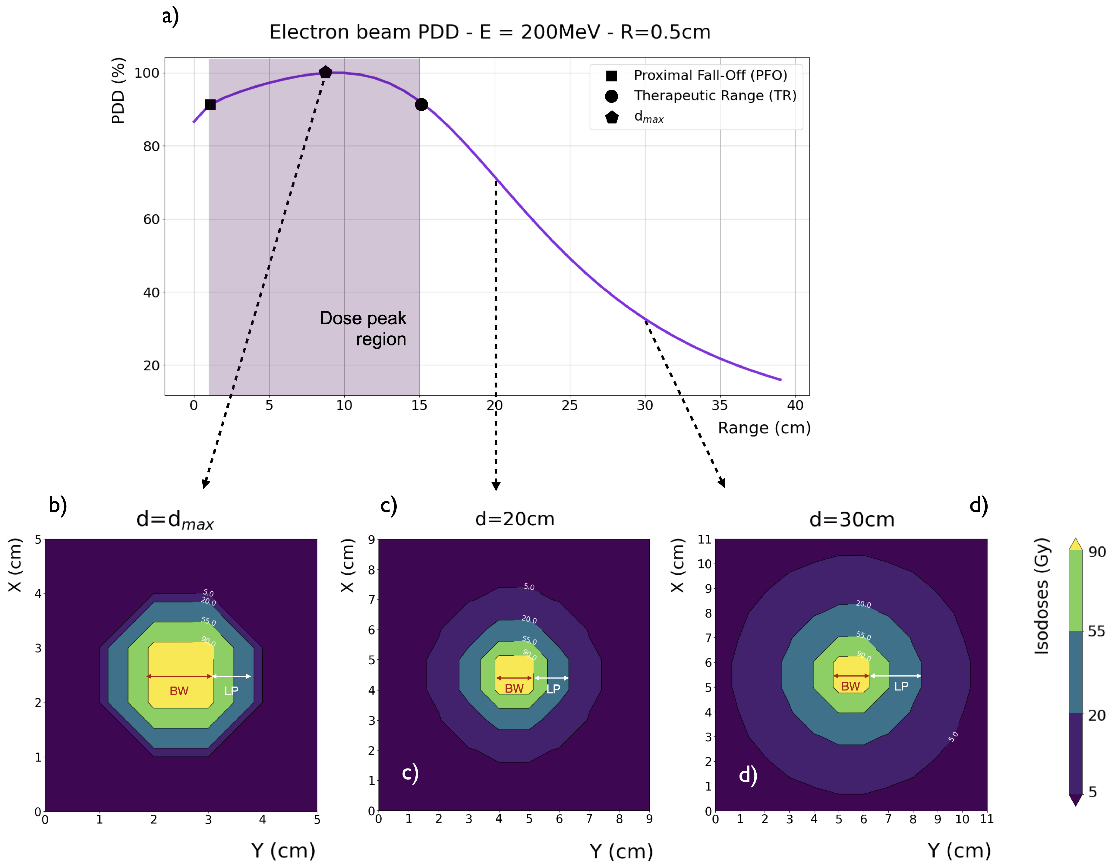
Figure 2.
Longitudinal on-axis (main) and integral (insert) dose distributions of collimated beams impinging on a water phantom (with vacuum beforehand). The beam energy varies from 50 to 300 MeV in 50 MeV increments. The beam diameters are a) 1 cm and b) 10 cm.
Figure 2.
Longitudinal on-axis (main) and integral (insert) dose distributions of collimated beams impinging on a water phantom (with vacuum beforehand). The beam energy varies from 50 to 300 MeV in 50 MeV increments. The beam diameters are a) 1 cm and b) 10 cm.
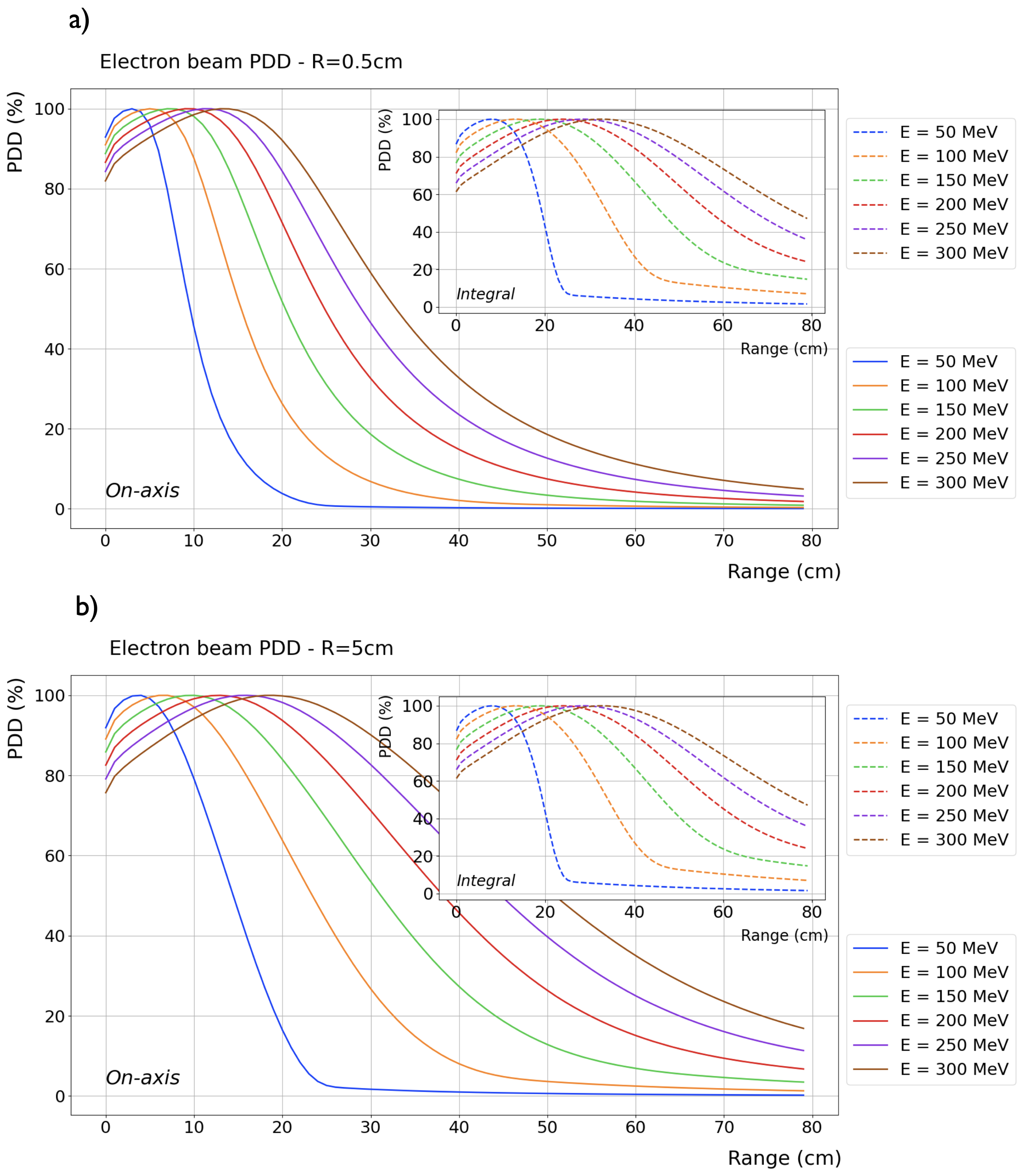
Figure 3.
FLASH vs. CONV-RT modality: inter-dependent temporal parameters characterizing the entire RT treatment, a single fraction, and a single pulse.
Figure 3.
FLASH vs. CONV-RT modality: inter-dependent temporal parameters characterizing the entire RT treatment, a single fraction, and a single pulse.
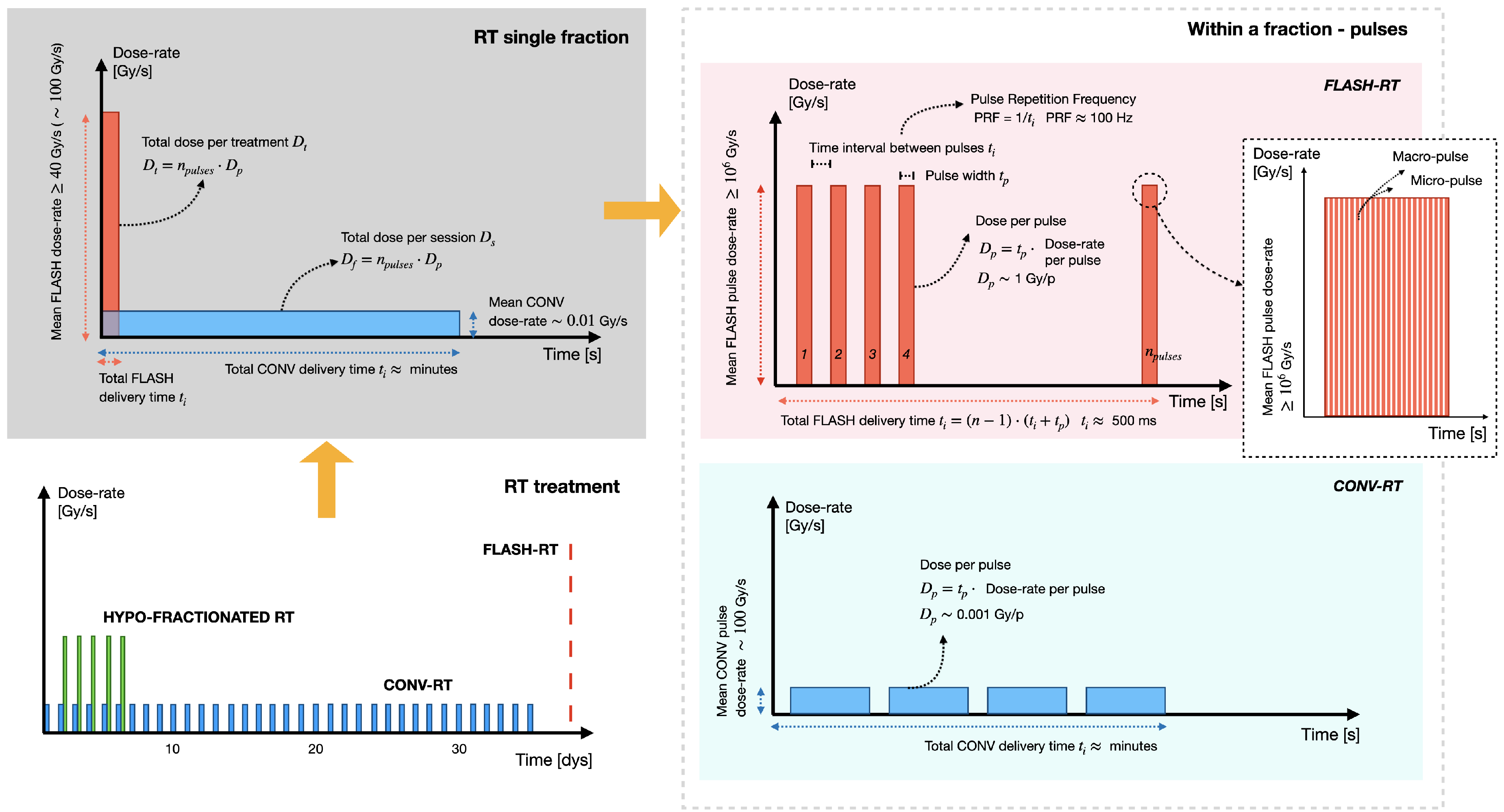
Figure 4.
Facilities currently being used worldwide for VHEE beam production are categorized as follows: Green for RF-based research linear accelerators (RF linacs), yellow for compact FLASH VHEET dedicated RF linac platforms, and red for research laser-plasma accelerators exploiting the WakeField effect. Listed under each facility are the papers based on research conducted at that center.
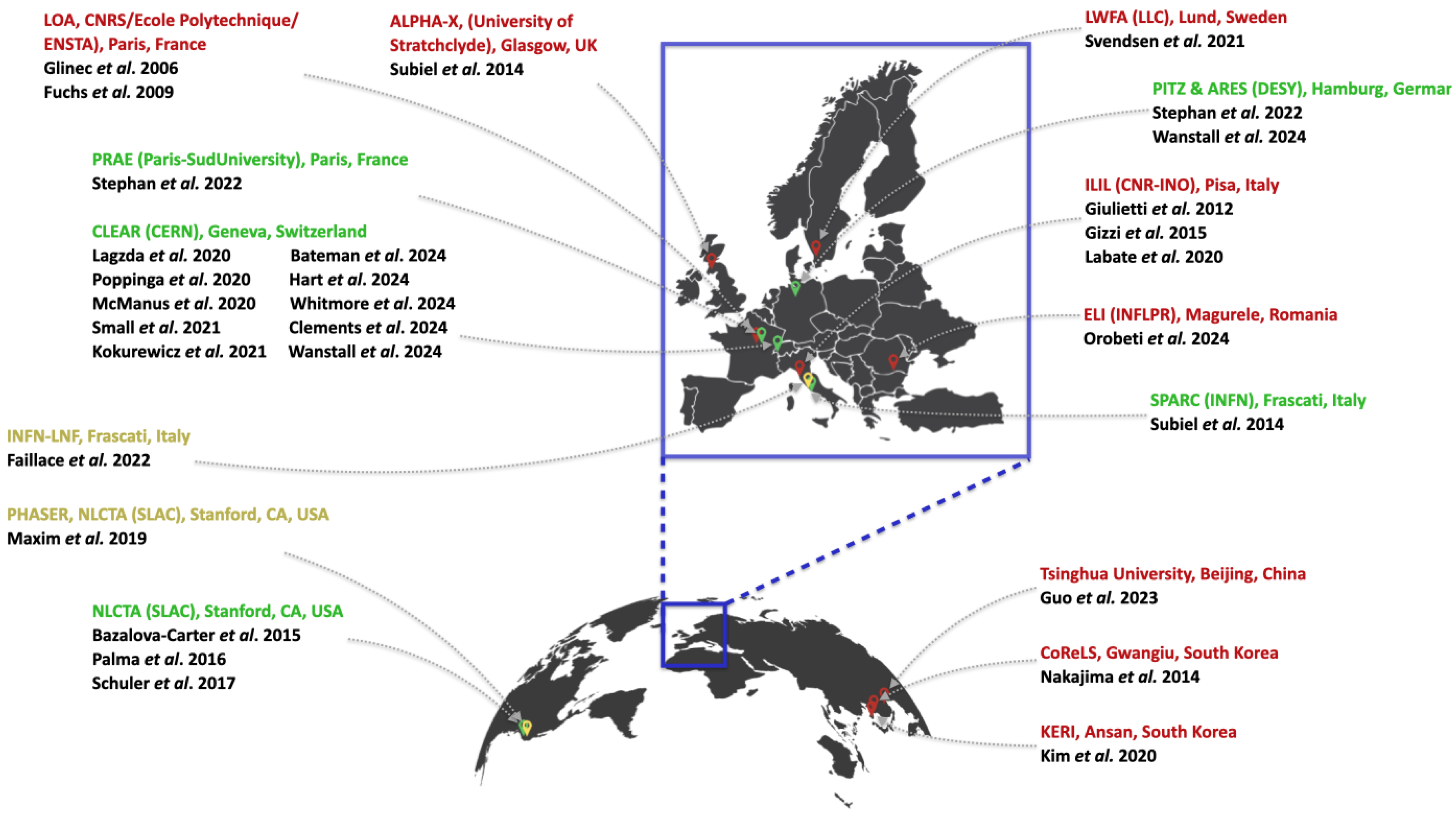
Figure 5.
Schematic representation of a linear accelerator (linac) and its main components: Electrons are generated by a particle source within a vacuum chamber, using either a cold cathode, a hot cathode, a photocathode, or an RF source. A microwave source, such as a klystron or magnetron, powers the accelerating waveguide, a series of open-ended cylindrical electrodes guiding the electron beam towards the diagnostic and manipulation (focusing) area. Finally, the VHEE beam reaches the user beamline.
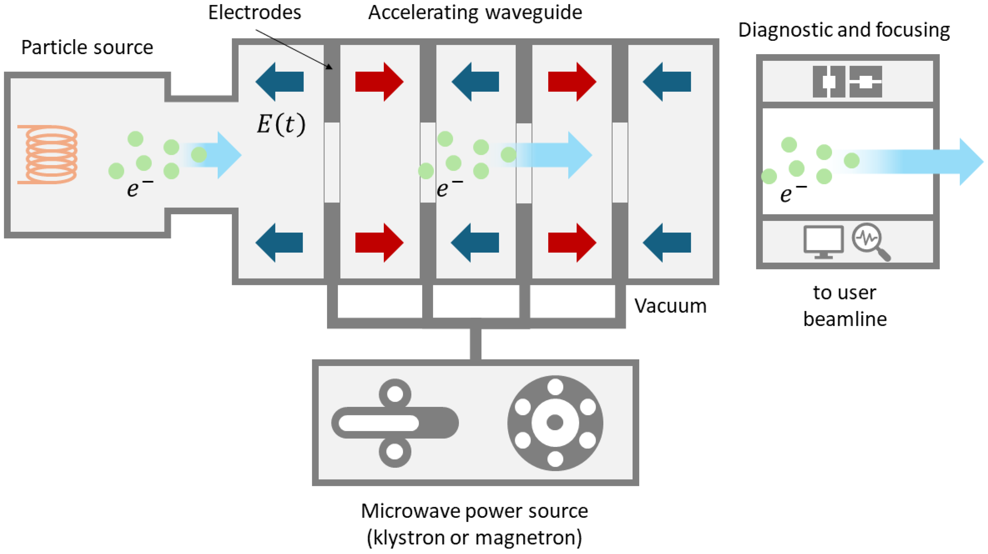
Figure 6.
Schematic representation of a laser WakeField accelerator with its main components. An ultra-short (∼10s of fs) laser pulse is generated, amplified, and transported to the interaction area. The laser pulse is then focused on a gas target, usually by an off-axis parabolic mirror. Electrons are accelerated within the plasma and propagate in the forward direction.
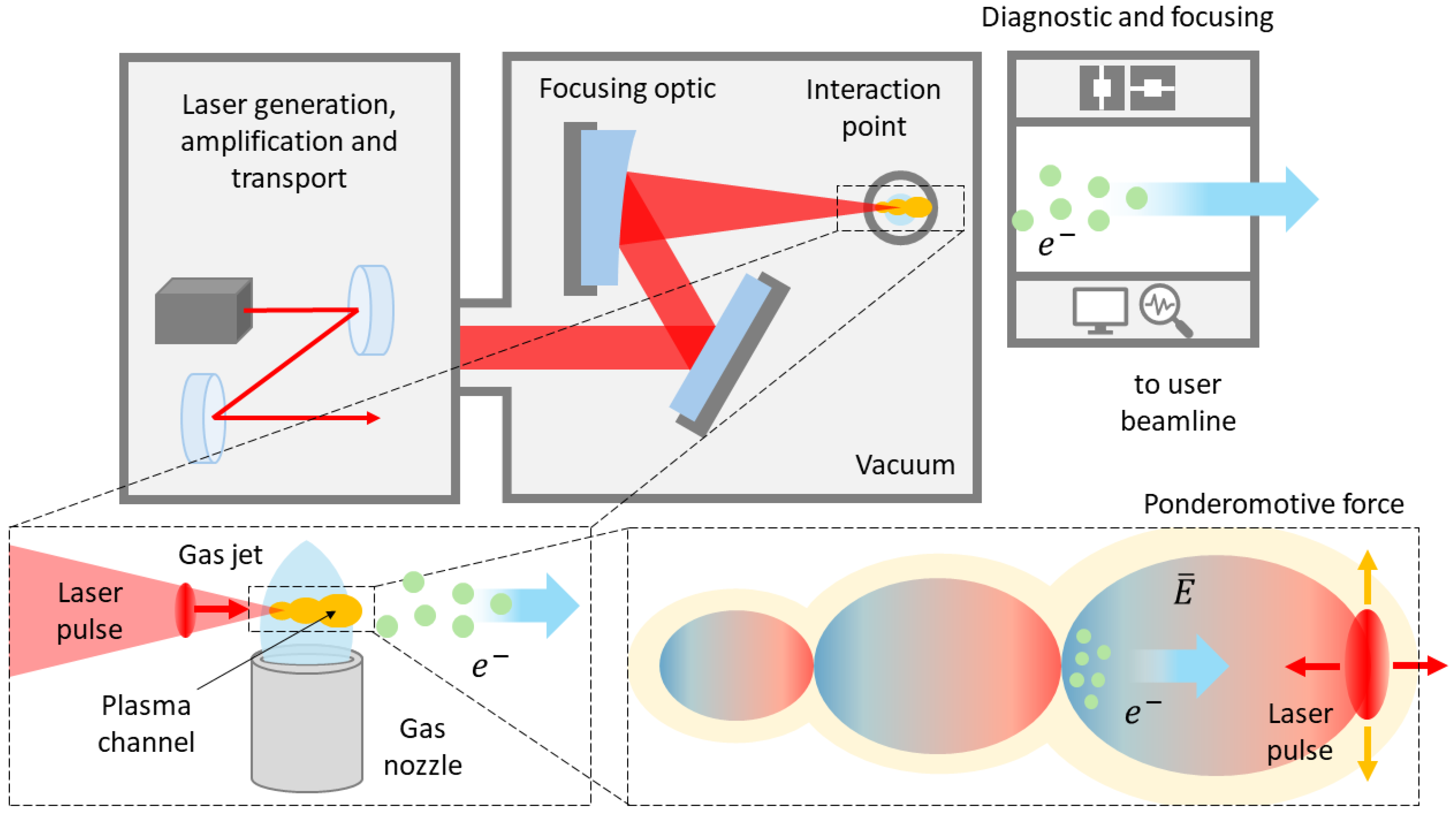
Figure 7.
Particle-In-Cell simulation artwork of laser WakeField electrons acceleration. The laser pulse propagates in an underdense "transparent” plasma, generating a strong longitudinal electric field, whose velocity is close to c, the WakeField. When electrons get trapped within the accelerating region of the electric field, their energy is boosted to very high values over very short distances.
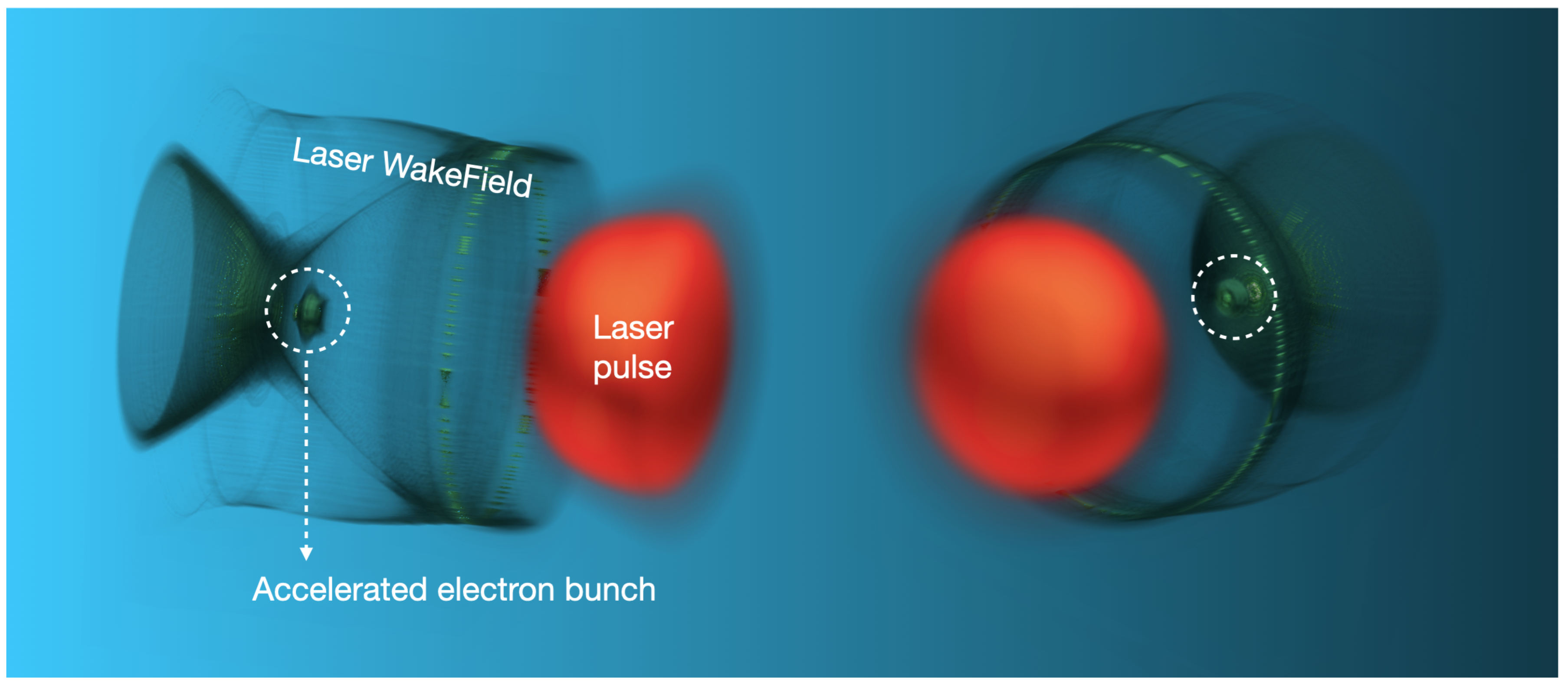
Figure 8.
Quadruple magnetic field lines.
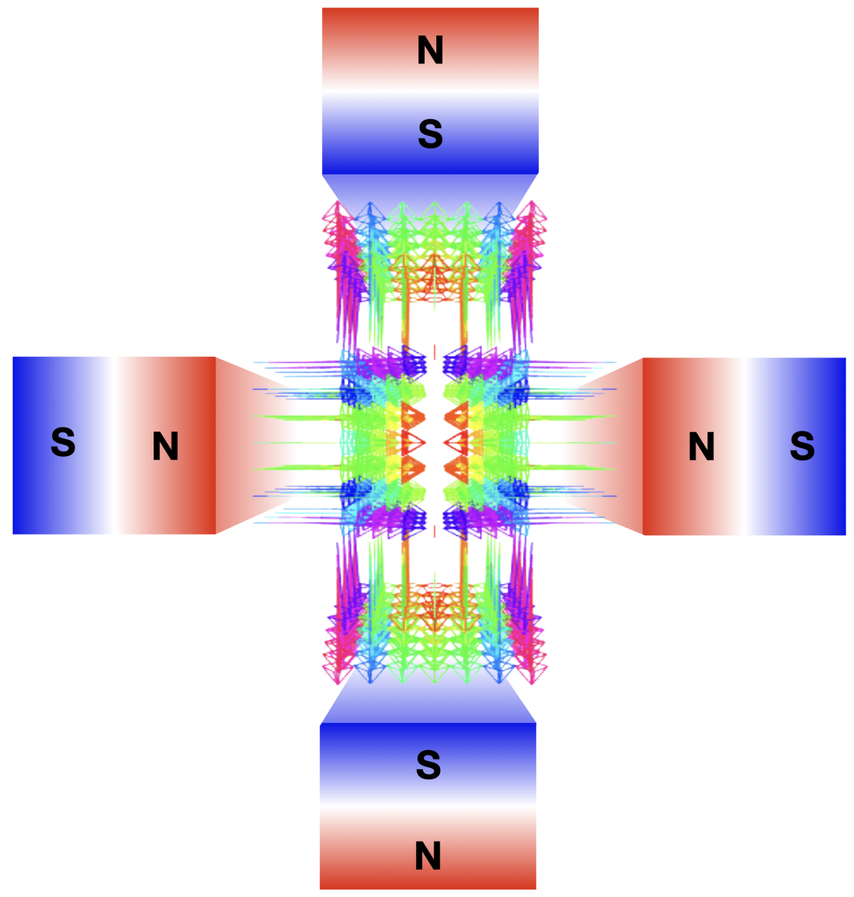
Figure 9.
VHEE beam focusing: a) focusing and b) de-focusing magnetic quadrupoles, graphic rendering from the thin lens approximation and matrix formalism. c) Drift graphic rendering and matrix formalism. The final focusing can be symmetric d), meaning the beam converge along both planes, or asymmetric e), with the beam converging along one plane only.
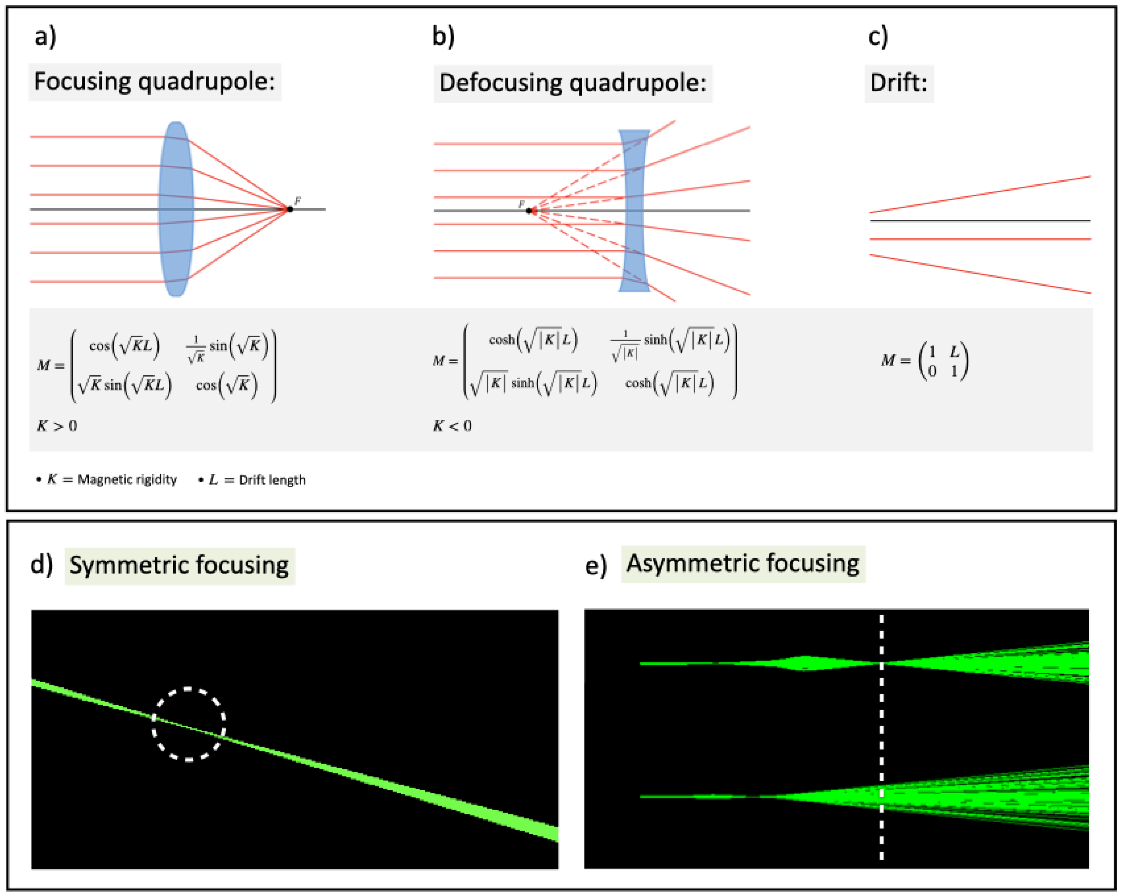
Disclaimer/Publisher’s Note: The statements, opinions and data contained in all publications are solely those of the individual author(s) and contributor(s) and not of MDPI and/or the editor(s). MDPI and/or the editor(s) disclaim responsibility for any injury to people or property resulting from any ideas, methods, instructions or products referred to in the content. |
© 2024 by the authors. Licensee MDPI, Basel, Switzerland. This article is an open access article distributed under the terms and conditions of the Creative Commons Attribution (CC BY) license (http://creativecommons.org/licenses/by/4.0/).
Copyright: This open access article is published under a Creative Commons CC BY 4.0 license, which permit the free download, distribution, and reuse, provided that the author and preprint are cited in any reuse.


