Submitted:
08 November 2024
Posted:
12 November 2024
You are already at the latest version
Abstract
As the complexity of structures and materials used in modern engineering increases, so does the need for more accurate and reliable methods of stress and strain monitoring. Strain gauges, in turn, are used to measure force or strain on the surface of an object. Strain gauges and strain gauge transducers are important tools in the field of materials resistance research to measure stresses and strains in solids. These methods and devices have a wide range of applications, from construction to mechanical engineering, where the mechanical properties of materials need to be monitored and optimized.
The paper considers different types of composites based on polymer matrices with additives of dispersed nanomaterials, which are designed for strain gauge tasks. Thermoplastics and elas-tomers can be used as polymer matrices. Dispersed fillers can be based on MXene and nano-materials: carbon nanotubes, graphene, metals, etc. Despite the obvious advantages of strain gauges based on conducting polymers modified with dispersed structures - there are problems of creating effective strain gauges with the ability to operate under large deformations with im-proved sensitivity and accuracy of measurements in a wide range.
The use of nanomaterials in strain gauges allows for more sensitive and compact sensors. Nanotechnology makes it possible to create strain gauges with improved mechanical and electrical properties. At the same time, nanomaterials have unique properties that make them ideal for use in strain gauges. The purpose of this review study is to determine the prospects for the use of various nanomaterials as additives in polymers to create strain gauges.
Keywords:
strain sensor
; strain gauge
; strain sensitivity
; polymer
; nanocomposite
; carbon nanomaterials
; carbon nanotubes
1. Introduction
Measurement of pressure and associated deformation and mechanical stresses acting on different types of surfaces of parts or devices is relevant in a wide range of technological and scientific and technical tasks [1]. Traditional and classical devices for strain gauge measurements may be insufficiently accurate or inconvenient for application in certain situations. This creates the need to develop more effective and convenient technical solutions for strain gauge tasks. The ability to measure mechanical deformations such as tension, torsion and compression is required in portable electronics devices [2], soft robotics [3], human motion parameter detection [4], virtual reality technology [5], human health monitoring [6], rock fracture research [7], strain gauging of car parts [8], mechanical engineering technology [9], aviation technology [10] and other various technical applications [11,12,13,14]. Strain gauge, strain gauge or strain resistor (from Latin tensus - "tense") is a load meter used in devices for determining the mass of a load (Figure 1).
Strain gauges are of high relevance for measurement technology, control and management systems [15]. The main sensitive element of strain gauges is a primary measuring transducer that generates an electrical signal under mechanical deformation. In 1843, S. Wheatstone described the effect of resistance change in an electric conductor under the action of mechanical strain. In 1938, E.E. Simons and A.C. Ruge invent, almost simultaneously but independently, the strain gauge. In 1952, the "metal-foil strain gauge" method is mentioned for the first time [16,17,18]. A strain gauge is defined as a change in the specific electrical resistance of materials caused by mechanical deformation [19]. Thus a strain gauge is a resistor whose electrical resistance changes depending on its deformation. This follows, in particular, from the well-known formula for the electrical resistance of a conductor:
where R is the resistance of the conductor, Ohm;
l – length, m; S – cross-sectional area of conductor, m2;
ρ – is the proportionality coefficient depending on the conductor material or specific resistance (Ohm∙m2)/m.
Formula (1) shows that when a conductor included in an electric circuit is deformed, its geometric parameters l and S change, hence its electrical resistance. A change in the electrical resistance of the conductor leads to a change in the electric current flowing in the circuit, which can be recorded by an electrical measuring device, including the use of a bridge circuit.
The wire resistance sensor (Figure 2) of the most common type with the so-called loop winding of the wire [20]. The sensor is based on thin paper 2, to which the sensor wire is glued, arranged in the form of several identical loops, forming the wire grid 1 of the sensor. To the ends of the sensor wire lattice are connected by soldering or welding leads 3 made of copper wire or foil, which are used to connect the sensor to the measuring equipment. The length of individual loops l is called the base of the wire resistance sensor. The wire grid of the sensor is usually sealed with another protective layer on top.
Often aluminum wire, film or foil are used as materials for strain gauges [21]. Commercial metal strain gauges have limited sensitivity and cover very small areas, and their typical operating voltage range is less than 3% [22]. When designing strain gauges, it is necessary to achieve high sensitivity, linearity, low hysteresis and temperature stability of measurements over the maximum possible range of strain variation [23]. Strain gauges have significant advantages, but there are some disadvantages associated with both temperature stability and special operating conditions. These data are summarized in Table 1.
One of the main problems faced by specialists in the field of mechanical load research is the need for accurate measurement of stresses and strains under various operating conditions [24]. Strain gauges and strain gauge transducers provide an opportunity to perform such control, which makes this area relevant and promising for further research and development in mechanics [25]. The disadvantage associated with temperature sensitivity can most often be corrected.
Nanomaterials for strain gauges appear to be innovative, which have unique mechanical properties and ability to respond to mechanical stress [26]. One of the main advantages of nanomaterials for strain gauges is their high sensitivity to mechanical stress at small dimensions. Due to this, such materials allow the development of more accurate and efficient strain gauges capable of operating in a wide range of conditions [27]. Animportant advantage of using nanomaterials for strain gauges is also their resistance to various external factors such as humidity, temperature and corrosion. This increases the lifetime and performance of strain gauges, which is especially important when they are used in extreme environments or in medical devices [28,29]. Polymer-based load cells containing nanomaterials have high mechanical strength, elasticity, and electrical conductivity, making them ideal for use in a variety of devices. Among the most promising nanomaterials for strain gauges are carbon nanotubes (CNTs) [30], graphene [28], carbon fibers [31], functionalized and modified nanomaterials [26,27,28,29,30,31,32].
Therefore, the aim of the review study is to determine the prospects of using var ous nanomaterials as additives in polymers to create strain gauges. In order to achieve the objective, the following tasks were set:
- -
- To consider the theoretical basis of strain gauging;
- -
- To study the types of strain gauge transducers and their characteristics;
- -
- Consider the possibility of using nanomaterials as filler in polymers for strain gauge;
- -
- Carry out a classification of modern load cells.
2. Applications of Strain Gauges
The application area of strain gauges includes a wide range of devices for various purposes, which requires the use of various types of strain gauges (Figure 3) to measure physical effects [33].
Strain gauges are used in several types of measuring instruments such as laboratory scales, industrial scales, platform scales and universal testing machines [34,35]. The principle of operation of strain gauges is based on the measurement of changes in the resistance of a material under mechanical strain. Strain gauges also find application in the production of scales, the use of which is common in various industries [36]. The principle of operation of electronic scales is to measure the force of gravity acting on the strain gauge and convert this force into a corresponding electrical output signal through strain.
Since 1993, the British Antarctic Survey has been installing load cells in fiberglass nests to weigh albatross chicks [37]. Strain gauges are used in a wide variety of products, such as the seven-post shaker that is often used to tune race cars [38]. Load cells are installed in hot beverage dispensers such as coffee and tea (Figure 4) to dispense the volume of liquid [39].
The column load cell is a column-type sensor used in truck, wagon, hopper and capacitance scales. Other names of the sensor are cylindrical sensor, compression sensor, "barrel" and tower load cell [40]. This load cell is made in two versions - digital or analog. Figure 5 shows a column load cell ZSFY-A/-SS (KELI sensing Technology, China) mounted for measuring the mass of trucks.
Other popular applications of strain gauges are summarized in Table 2.
Category I - studies of physical properties of materials and structures, where a large number of measurement points, wide ranges of parameter changes and impossibility to calibrate measurement channels are required. The error in such cases ranges from 2% to 10%;
Category II - measurement of mechanical quantities, where the sensors are graded by the measured quantity and the errors are in the range from 0.5% to 0.05%.
Figure 6 presents a block diagram of the algorithm of strain gauge selection for various technical applications (medicine, construction, science, engineering, aviation and automotive, etc.), which includes the following components: material selection; installation; resistance measurement; transformation of strain value; interpretation of the results of resistance change measurement. The causes of measurement errors (stochastic and systematic) when using strain gauges can be related both to the measurement method, the way of its realization, and a number of external factors. Incorrect installation or fixation of the load cell on the object of measurement can distort the results by forming a measurement error. Excessive mechanical load on the load cell can lead to its damage or deformation. Insufficient stabilization of environmental parameters before measurement, such as temperature or vibration changes, can also affect the accuracy of the results. Improper calibration prior to measurement can lead to inaccurate results. Wear or damage to load cell components can cause distortion in the measurement data. Electrical interference can also cause measurement errors. Incorrect data processing and interpretation, as well as insufficient understanding of the principles of strain gauge operation, can also cause errors [18].
Various methods are used to compensate for temperature error in strain gauges. One way is to use compensating elements such as thermistors or thermocouples to monitor temperature changes and adjust the measurements accordingly. Another way is to use special materials to make strain gauges that have more stable characteristics with temperature changes. Software compensation methods are also used, when special algorithms are used to process the received data and correct them according to known temperature dependencies. In addition, compensation is possible by installing temperature sensors near the strain gauges and using these data to correct the measurements.
3. Types, Types and Properties of Load Cells
3.1. Types of Load Cells
To date, strain gauges can be categorized into three main types: wire, foil, and film (Figure 7).
As an example, Figure 7 c shows a film strain gauge RFP602 (China) for measurements in the range of 0...1 kg. RFP602 strain gauges are installed in Wavgat (China) strain gauges and table electronic scales for measuring small items, e.g. precious metals. Film analog strain gauge RFP602 with a maximum allowable load of 1 kg changes resistance under the action of applied force. The diameter of the sensing part is 10 mm.
3.1.1. Wire Strain Gauges
Wire strain gauges in measurement technology are used in two main directions [43,44]. In the first case, the tenso-effect of a pressurized conductor is used. A coil of wire, usually made of manganin, is placed in the area of gas or liquid pressure measurement, and the change in the active resistance of the wire serves as the output signal of the transducer. In the second case, the tenso-effect of a tensile wire made of a stress-sensitive material is used. Strain gauges can be "free", where the wire is fixed between two elements and acts as an elastic element, or adhesive. Adhesive strain gauges consist of a wire sensor attached to a substrate using thin paper or film. The wire is usually zigzag shaped and has a diameter of 0.02 to 0.05 mm. The ends of the wire are connected to lead wires and the sensor is coated with a layer of varnish, sometimes additionally protected with paper or felt.
3.1.2. Foil Load Cells
Foil load cells are one of the most common types of adhesive sensors. Because of the possibility of increasing the area of the leads, a more reliable contact connection is provided compared to wired sensors [45,46,47]. They are a thin strip of foil from which some of the metal is removed, forming a grid with leads. The advantage of foil strain gauges is the possibility of creating a variety of meshes, which makes them more flexible. They can be used to measure both linear stresses and torques, for example when glued to a shaft or diaphragm [48]. Compared to wire transducers, foil strain gauges offer several advantages, such as larger surface area and smaller cross-section, which ensures stable operation at high temperatures and long-term loads [49]. Meanwhile, the large surface area also improves the temperature contact with the sample, which reduces self-heating. Foil voltage sensors have a high ratio of sensing element to cross section (sensitivity). This ensures their stability at high temperatures and long term loads [50]. In the process of creating foil sensors, metals such as constantan and nichrome, as well as various materials, including titanium-aluminum alloy, are used. The latter provides the ability to measure strains up to 12%. In addition, semiconductor materials are also used. Materials for foil load cells are presented in Table 3.
For constantan foil with epoxy backing, the recommended range is about -75 to +205 ºC and the maximum temperature is -200 to +315 ºC.
3.1.3. Strain Gauge Transducers
The 3rd type of strain gauge transducers are film transducers. Strain gauge transducers can be made on the basis of metal or semiconductor film [51,52,53]. Figure 8 shows a semiconductor strain gauge.
Production of film strain gauges is carried out by deposition of sensitive material on a substrate. The thin layer of such strain gauges is ~15-30 μm and has a significant advantage when measuring strains in dynamic mode, as well as at high temperatures. Film strain gauges based on bismuth, titanium, silicon, germanium, etc. are known [54,55,56]. They are in the form of a single conductive strip and are not subject to a decrease in sensitivity with respect to the material from which they are made. For strain gauge transducers based on metal film, the strain ratio ranges from 2 to 4 and the resistance is in the range of 100 to 1000 ohms. Transducers based on semiconductor film have a much larger range of coefficients: from 50 to 200. They are more sensitive to voltage, so they do not require amplifiers. The output voltage of a semiconductor strain gauge bridge can be as high as 1 volt. However, note that the resistance of the semiconductor transducer varies with voltage and has a non-linear characteristic. An amplifier is required to work with a metal film based strain gauge. The linearity of this transducer is very high, which effectively compensates for the effect of temperature. Thus, the transducers based on metal and semiconductor film have their own features, but provide the necessary functionality according to specific requirements and application conditions [57]. This type of strain gauge transducers has high thermal stability. The evaluation of the feasibility of a high-temperature Pt-based thin-film resistor at a temperature of 700 °C and 5 cycles is presented in Figure 9 [54].
3.2. Calculation of Main Parameters of Strain Gauges
The main characteristic of a strain gauge is the relative strain sensitivity coefficient K, the ratio of the change in resistance to the change in conductor length:
where ‒ is the relative change in resistance of the conductor;
‒ is the relative change in conductor length.
A change in the length of solids is associated with a change in volume, and their properties and the value of resistivity ρ change accordingly (1). The value of the strain-sensitivity coefficient is expressed from the formula:
(1+2μ)‒ characterizes the change in resistance by geometric measurements (length and cross-section) of the conductor, and m characterizes the change in specific resistance of the material by physical properties.
Manufacturing of strain gauge transducer using semiconductor materials makes it possible to determine sensitivity mainly through the change in the material properties of the grating when it is deformed. The sensitivity factor K≈m can vary for different materials from 40 to 200. Typical values of strain sensitivity coefficient for different materials, including carbon nanomaterials such as carbon nanotubes (CNTs) and multilayer nanotubes (MWCNTs) are summarized in Table 4.
Having thus analyzed the main types of sensors (wire, foil and film) and their properties, we can highlight their strengths and weaknesses, which are summarized in a comparative table 5.
3.3. Connection Method of Strain Gauge Transducers
There are several types of strain gauge transducers, according to the method of connection for measuring resistance under strain [1,15,19]:
1. Semi-bridged. This is the most common type (Figure 9). They have two strain resistors connected as a half-bridge. One resistor is in the deformed zone and the other in the non-deformed zone, which allows to compensate for temperature effects and improve measurement accuracy.
2. Bridged. This uses four strain gauges forming a bridge circuit. This provides high sensitivity and stability in strain measurement.
3. Multi-point strain gauges. These transducers have multiple sensing elements to measure strains at different points on the object. This is useful for estimating stress distributions.
4. Integral. These are also referred to as "voltage sensors". They are built directly into the design and can measure voltages in real time.
5. Centrally symmetrical. They are used for measuring uniaxial deformations. They have two sensing elements arranged symmetrically about the center.
Each type of strain gauge transducer has a number of features that allow its application depending on the required accuracy, type of deformation and other measurement parameters. Figure 10 shows a half-bridge strain gauge transducer.
3.4. Classification of Strain Gauges
The nominal value of the maximum perceived load of load cells ranges from 5 H and over 50 MH. They have become the most widely used of all measuring systems and can be used as a standard for force transmission with high-resolution digital displays [1]. At the same time, load cells differ depending on the type of load and their design features. Cantilever (beam), S-beam, diaphragm (washer), column (rod) and torsion load cells are used for different types of measurements (Figure 11).
To summarize the information presented, strain gauges can be classified based on several factors, as shown in Figure 12.
4. Strain Gauges Based on Polymer Composites Containing Carbon Nanostructures
Recently, there has been considerable interest in the development of strain gauges based on polymers with conductive fillers [81]. One option for producing strain gauges is to use polymers filled with conductive materials and, in particular, carbon dispersed structures [82]. Among carbon nanomaterials (Figure 13), the most effective are CNTs, the use of which allows measuring small deformations with high accuracy [83,84]. At the same time, CNTs have high strength and elasticity, which allows creating very sensitive sensors. Graphene is an allotropic modification of carbon, which has high electrical conductivity and can be used to create sensors with a fast response and high measurement accuracy.
MWCNTs show good results in the field of strain gauge creation, which is related to their unique electromechanical properties [68,69,70,71,72,73,74,75,76,77,78,79,80,84,85]. The conducted studies in the field of strain gauges show which aspects of using CNTs for strain measurement, both at the nano- and macro-levels, are of great importance. In this case, the main method for obtaining a polymer composite containing CNTs is mixing, as shown in Figure 14.
First of all, CNTs undergo changes in their band structure under the influence of mechanical deformations [87]. The electrical resistance of CNTs increases linearly with increasing strain, which makes it an ideal material for piezoresistive strain sensors. Conductive composite films can be made by blending single-walled or multi-walled CNTs with polymers to improve the performance of strain sensors [88]. Studies also show that CNTs exhibit stable and predictable stress response as a function of temperature.
It should be noted that polymer nanocomposites have a high calibration coefficient and stable response to mechanical stress [89]. Nanocomposites based on polymer matrices are optimal for measuring large deformations (> 10%), which is especially important for applications such as intelligent robots and human motion monitoring. When a densely packed array of CNTs is stretched, the configuration of their network changes, which leads to a change in its electrical resistance (ΔR) [90], as shown in Figure 15.
The polymer coating the CNT array affects its piezoresistive response not only during the first loading but also during subsequent (cyclic) loading. Such a response may depend on the dielectric and mechanical properties of the polymer coating (Figure 16).
This is mainly influenced by the contact between individual CNTs, tunneling and electron hopping, which depend on the distance between individual CNTs (Figure 17).
Thin-film CNT sensors also exhibit resistance hysteresis under cyclic strain loading [92], which is due to irreversible degradation of the CNT/polymer interface. Temperature can also cause changes in the electrical resistance of the strain gauge. For piezoresistive strain gauges, these temperature-induced changes in electrical resistance can be misinterpreted as strain. Thus, the thermoresistive response of strain gauges also needs to be characterized to account for potential temperature compensation factors of the strain gauges.
Commercial strain gauges have a sensitivity factor of 2 with compensated temperature coefficient of resistance (TCR). In this case, it is necessary to use strain gauge materials with a high calibration factor and a small TCR. The effect of self-compensation of strain gauges can be achieved by combining a semiconductor material with a negative TCR with a high calibration factor and a metal with a positive TCR, leading to a TCR close to zero. Alternatively, nickel-containing diamond-like carbon films (Ni-DLC or aC:H:Ni) and Ag-ITO compounds can be used, which allows achieving zero-crossings in the TCR and calibration factors above 10 [58].
The geometry of the conductive mesh of a CNT strain gauge has an important effect on its piezoresistive response [93]. The main physical mechanism of sensitivity to mechanical action is based on a change in geometric dimensions that occurs during deformation from an external effect, which leads to a change in the electrical resistance of the sensor material, which is measured using controllers with analog-to-digital converters [94]. Three calibration methods can be used to improve the accuracy of sensors: single-point, two-point, and three-signal [95]. The optimal option is a direct connection of the strain gauge to the microcontroller [96], and in this regard, strain gauges should provide good metrological characteristics ‒ accurate measurement of small and large deformations. The use of a polymer matrix type is of key importance in the formation of a strain gauge [97]. The cohesion of filler particles and their dispersion in the composite depend on it, affecting the mechanical and electrophysical characteristics of strain gauges based on them [98]. Improving the distribution of MWCNTs in the polyurethane (PU) matrix reduces the percolation threshold and improves the electrical conductivity and strain-sensing properties of MWCNT-filled PU nanocomposites. In this way, the calibration coefficients can be improved in both small and large strain regimes. Elastomers with a uniform distribution of CNTs have increased strain resistance, as well as improved strength and tunable sensitivity. In [99], it was shown that the resistance of CNT-polymer strain gauges changes with time, both with and without strain, which leads to several limitations that need to be overcome before CNTs can be used as sensing materials for polymer composite strain gauges. It is necessary to improve the reproducibility of the measurement results, as well as their stability. Reproducibility is related to the repeatability of the resistance-strain characteristics with the stability of the measured resistance over a long period of strain gauge operation. The resistance of CNT thin films varies depending on a number of factors such as strain, defects, temperature, chemical influences and size effects [100].
Thus, polymers filled with CNTs are promising materials possessing a number of properties preferable for strain measurement, such as flexibility, resistance to aggressive environments (anti-corrosion properties), small weight and size dimensions, etc. At the same time, in polymer composites, the strain sensitivity characteristics can be tuned for various applications by changing the morphology of the conductive structures and composition. The conductivity of such composites usually changes nonlinearly and has an exponential character, while the conductivity of the matrix increases significantly (by several orders of magnitude) upon reaching the percolation threshold. With increasing deformation or under compressive stress, the geometry and length of the conductive networks present in the matrix change, which in turn leads to a deformation-dependent change in electrical resistance [89,101]. In most cases, such changes are reversible and have a wider range than the changes observed in their metallic analogs. The diversity of characteristics and the wide range of electrophysical properties observed in polymers modified with carbon nanomaterials allow them to be classified as the so-called class of “intelligent” or “smart” materials for strain gauge measuring transducers (strain sensors) [68,69,70,71,72,73,74,75,76,77,78,79,80,102].
It is necessary to take into account modern technological capabilities when using polymer composites associated with the use of 3D printers [103], which allows obtaining sensors with stable parameters [104]. Therefore, despite the obvious advantages of strain gauges based on polymers modified with dispersed conductive structures, there are problems in creating effective strain gauges with the ability to operate under conditions of large deformations with improved sensitivity and measurement accuracy. That is, directly implementing the effect of self-compensation of strain gauges when combining a semiconductor material with a negative TCR with a high calibration coefficient and a metal with a positive TCR, as well as improved resource characteristics - allowing for long-term operation with multiple compression / decompression modes. At the same time, individual tasks associated with strain measurement require their own approach, which can be implemented based on the selection of various options for polymer matrices and synthesized conductive metallized carbon nanostructures [105].
5. Modern Strain Gauge Technologies Using Polymer Composites
There are several emerging trends and developments in strain measurement that are making significant contributions to modern strain and stress measurement techniques [101,106,107,108]:
1. Nanotechnology. The use of nanomaterials in strain measurement allows for the creation of more sensitive and compact sensors. Nanotechnology allows for the creation of strain gauges with improved mechanical and electrical properties. Nanomaterials have unique properties that make them ideal for use in strain gauges. The use of nanotechnology in strain measurement also allows for the creation of wireless sensors that use nanomaterials to transmit data wirelessly. This opens up new possibilities for monitoring and controlling various processes, as the sensors can be placed in hard-to-reach places without the need for wired communication.
2. Wireless strain gauges. The development of wireless communication technologies allows for the creation of strain gauges that can transmit strain and stress data wirelessly. This is especially useful in cases where wired connections are inconvenient or impossible. Wireless strain gauges are strain gauge transducers that can transmit data without using wires. They are widely used in various fields where it is necessary to measure stress, strain, or weight and transmit this data to a remote device for analysis or monitoring. This is especially convenient in cases where wires may be damaged or interfere with the environment. Wireless strain gauges can be used in various fields such as medicine, automotive, construction, industry, and sports. They provide accurate and reliable measurement and transmission of data, which makes them an important element in modern technologies [108].
3. Integration with the Internet of Things (IoT). Strain gauges integrated with IoT technologies can transmit strain and strain data in real time, which allows you to monitor and control the condition of structures and equipment remotely. Integrating strain gauges with IoT opens up new prospects for monitoring and controlling various processes. Connecting strain gauges to the IoT network allows you to transmit strain and stress data in real time to a remote server for analysis and decision making [109]. Data on deformations and stresses can be transmitted in real time, which allows for a prompt response to changes and the necessary adjustments. Thanks to the Internet connection, data from strain gauges can be accessed from anywhere in the world, which is especially important for remote monitoring of objects. The use of IoT allows for the automation of data collection and analysis processes, which reduces the risk of errors and increases the efficiency of the monitoring system. Accurate and timely information on deformations and stresses makes it possible to use resources more efficiently and prevent emergency situations [110].
4. Data modeling and analysis. Modern methods of machine learning, data analysis and artificial intelligence (AI) allow for more accurate and efficient processing of data obtained from strain gauges, identifying patterns and predicting the behavior of structures and materials [111].
5. Miniaturization and integration. New developments are aimed at creating more compact and lightweight strain gauges, which makes them more convenient to use and allows for an expansion of their scope of application. These new trends and developments in strain gauge technology promise to significantly improve the accuracy, ease of use and wide range of applications of strain gauges in various industries and sciences [112,113].
The development of strain gauge technology promises to be innovative and exciting. New materials and technologies will enable the creation of more sensitive and resolving strain gauges. Integration with other sensors and technologies, such as microcontrollers and optical systems, will increase their functionality. Wireless data transmission technologies will make their installation and use more convenient. Software developments will improve data analysis and processing. New calibration and error compensation methods will increase measurement accuracy. All this will make strain gauges more accurate, convenient and versatile for various fields of science and industry.
In addition, trends in strain gauge development point to wider application in various fields such as biomedicine, sports, robotics and the automotive industry. The development of hybrid and integrated systems will allow for the creation of more compact and efficient devices for measuring stress and strain. Improvements in the environmental and energy characteristics of strain gauges are also expected, which will facilitate their wider application in various areas of life, including miniature devices.
In addition, nanomaterials and nanotechnologies aimed at creating polymer composite materials will be able to create strain gauges with even higher sensitivity and resolution. The use of artificial intelligence and machine learning in the analysis of strain gauge data will improve the accuracy and speed of information processing. There is also a tendency to create more flexible and universal strain gauges capable of operating in various conditions and on various surfaces, which will make them more attractive for a wide range of applications. It should be noted that further development of nanotechnology and synthesis methods will make it possible to create even more advanced nanomaterials for strain gauges with improved characteristics and new functionality. This opens up broad prospects for the use of such materials in various fields. There are 4 main areas of application of polymer composite strain gauges:
1. Medicine. Nanomaterials make it possible to create thin and flexible strain gauges based on biologically safe polymers, which can be used to monitor biomechanical parameters in medical applications, such as measuring vascular pressure or monitoring cardiac function [114].
2. Construction and engineering. Nanomaterials make it possible to create strain gauges with high accuracy and sensitivity for monitoring stresses and strains in structures and machines [115].
3. Electronics. Nanomaterials are used to create ultra-thin strain gauges that can be integrated into electronic devices for measuring mechanical parameters [101,116].
4. Technological processes in the chemical industry. Measuring the level of cavitation in liquids with various parameters, including aggressive environments [117].
In general, the prospects for the development of strain gauge technology promise a significant improvement in its characteristics and an expansion of its scope of application.
6. Conclusions
Thus, in accordance with the objectives of the review study, the following conclusions can be drawn:
1. Strain measurement plays a key role in modern measurement technologies, providing accuracy and reliability in measuring strains and stresses in various materials and structures;
2. A variety of strain gauge types, such as wire, foil and film, allows you to choose the most suitable option for a specific application, taking into account the requirements for sensitivity, size and cost of measuring equipment;
3. With the advent of new technologies in the field of nanomaterials and microelectronics, further development of strain measurement is expected, including the creation of more accurate and compact transducers with improved characteristics.
4. The use of strain measurement is not limited to the field of strength of materials, but also finds application in medicine, automotive, aerospace and other areas where accurate measurements of strains and stresses are required.
5. Further research in the field of strain measurement will create more efficient and innovative measurement methods, contributing to the development of science and technology in general. The development of nanoelectronics and nanomaterials technologies opens up new opportunities for creating more sensitive and compact strain gauge transducers. Nanomaterials such as carbon nanotubes or graphene can be used to create highly sensitive sensors with low power consumption.
6. An important area of strain gauge development is improving methods for compensating for temperature effects on measuring devices. This will improve the accuracy of measurements (reduce the error) in a wide range of temperatures and operating conditions.
7. With the development of the Internet of Things (IoT) and smart technologies, strain gauge can become a key technology for monitoring the condition of infrastructure, building structures, vehicles and other objects, which will make it even more in demand in various industries. An important aspect of strain gauge development is also improving the methods for processing and analyzing data obtained from strain gauge transducers. This will help improve the accuracy and reliability of the measurement results.
8. Despite the obvious advantages of strain gauges based on polymers modified with dispersed conductive structures, there are problems in creating effective strain gauges that have the ability to operate under conditions of large deformations with improved sensitivity and measurement accuracy.
Author Contributions
Conceptualization, Aleksei V. S. and Alexander.V. S.; software, M.A.K.; validation, V.V.K. and M.A.K.; formal analysis, M.A.K.; investigation, Aleksei V. S.; resources, Alexander.V. S.; data curation, M.A.K.; writing—original draft preparation, Aleksei V. S.; writing—review and editing, Aleksei V. S.; visualization, Aleksei V. S.; supervision, V.V.K.; project administration, Alexander.V. S.; funding acquisition, Aleksei V. S. All authors have read and agreed to the published version of the manuscript.
Funding
Aleksei V. Shchegolkov is thankful for financial support from the Ministry of Science and Higher Education of the Russian Federation (State assignment FZRR-2024-0003).
Data Availability Statement
The data presented in this study are available on request from the first author.
Acknowledgments
This work was carried out with the financial support of the Ministry of Science and Higher Education of the Russian Federation (State assignment FZRR-2024-0003).
Conflicts of Interest
The authors declare no conflicts of interest. The funders had no role in the design of the study; in the collection, analysis, or interpretation of the data; in the writing of the manuscript; or in the decision to publish the results.
Abbreviations
TCR – temperature coefficient of resistance;
NTR – negative temperature coefficient of resistance;
PTR – positive temperature coefficient of resistance;
CNT – carbon nanotubes;
MWCNTs – multiwalled carbon nanotubes;
PDMS – polydimethylsiloxane;
PU – polyurethane;
TPU – thermoplastic polyurethane;
IoT – Internet of Things;
AI – artificial intelligence
References
- Kamble, V.A.; Shinde, V.D.; Kittur, J. K. Overview of Load Cells. J. Mech. Eng. 2020, 6(3), 22–29. [Google Scholar]
- Yao, H.; Cao, H.; Li, J. Design and Implementation of a Portable Wireless System for Structural Health Monitoring. Measurement and Control. 2016, 49(1), 23–32. [Google Scholar] [CrossRef]
- Choe, J.K.; Kim, J.; Song, H.; Bae, J.; Kim, J. A soft, self-sensing tensile valve for perceptive soft robots. Nature communications. 2023, 14:3942, 1-10. [CrossRef]
- Wang, F.; Yu, H.; Ma, X.; Lv, X.; Liu, Y.; Wang, H.; Wang, Z.; Chen, D. A Highly Sensitive Strain Sensor with Self-Assembled MXene/MultiWalled Carbon Nanotube Sliding Networks for Gesture Recognition. Micromachines 2024, 15, 1301. [Google Scholar] [CrossRef]
- Tuli, A.; Singh, A.P. Polymer-based wearable nano-composite sensors: a review. Int. J. Polym. Anal. Charact. 2023, 28(2), 156–191. [Google Scholar] [CrossRef]
- Abubakre, O.K.; Medupin, R. O.; Akintunde, I.B.; Jimoh, O.T.; Abdulkareem, A.S.; Muriana, R.A; James, J.A.; Ukoba, K.O.; Jen, T.-C.; Yoro, K.O. Carbon nanotube-reinforced polymer nanocomposites for sustainable biomedical applications: A review. Journal of Science: Advanced Materials and Devices. 2023, 8(2), 2468–2179. [Google Scholar] [CrossRef]
- Ma, H.; Wang, J.; Qian, J.; Luo, Q.; Wei, X. Experimental investigations of fractured rock deformation: A direct measurement method using strain gauges. Journal of Structural Geology. 2023, 171, 104869. [Google Scholar] [CrossRef]
- Pástor, М.; Živcák, J.; Puškár, M.; Lengvarský, P.; Klacková, I. Application of Advanced Measuring Methods for Identification of Stresses and Deformations of Automotive Structures. Appl. Sci. 2020, 10, 7510; [Google Scholar] [CrossRef]
- Dubey, K.A.; Mondal, R.K.; Grover, V.; Bhardwaj, Y.K.; Tyagi, A.K. Development of a novel strain sensor based on fluorocarbon–elastomeric nanocomposites: Effect of network density on the electromechanical properties. Sensors and Actuators A: Physical. 2015. 221, 33-40. [CrossRef]
- Festin, N.; Plesse, C.; Pirim, P.; Chevrot, C.; Vidal, F. Electro-active Interpenetrating Polymer Networks actuators and strain sensors: Fabrication, position control and sensing properties, Sensors and Actuators B: Chemical. 2014, 193, 82-88. [CrossRef]
- Cetin, M.S.; Toprakci, H.A.K. Flexible electronics from hybrid nanocomposites and their application as piezoresistive strain sensors. Composites Part B: Engineering. 2021, 224, 109199. [Google Scholar] [CrossRef]
- Pratt, L.; Bisson, C.; Warin, T. Bringing advanced technology to strategic decision-making: The Decision Intelligence/Data Science (DI/DS) Integration framework. Futures. 2023, 152, 103217. [Google Scholar] [CrossRef]
- Tung, S.; Witherspoon, S.R.; Roe, L.A. ; Silano, Al; Maynard, D. P.; Ferraro, N. A MEMS-based flexible sensor and actuator system for space inflatable structures. Smart Mater. Struct. 2001, 10, 1230. [Google Scholar] [CrossRef]
- Sharma, S.; Verma, A.; Rangappa, S.M.; Siengchin, S.; Ogata, S. Recent progressive developments in conductive-fillers based polymer nanocomposites (CFPNC's) and conducting polymeric nanocomposites (CPNC's) for multifaceted sensing applications. Journal of Materials Research and Technology. 2023, 26, 5921–5974. [Google Scholar] [CrossRef]
- Tutak, P. Application of Strain Gauges in Measurements of Strain Distribution in Complex Objects. JACSM. 2014, 6(2), 135–145. [Google Scholar] [CrossRef]
- Keil, S. On the strain gage’s 50th jubulee – a review of its evolution and of 33 years strain gage production at Darmstadt. RAM. 1988, 4(2), 39–48. [Google Scholar]
- Stein, P.K. Strain gage history and the end of the twentieth century, Exp. Techn. 2001, 15–16. [CrossRef]
- Hoffmann K. An Introduction to Stress Analysis and Transducer Design using Strain Gauges. HBM Test and Measurement 2012, p.240.
- Gürkan İrsel Research on electrical strain gages and experimental stress analysis: Case study for a full wheatstone bridge. DUJE (Dicle University Journal of Engineering). 2021, 12:5, 783-792. [CrossRef]
- Hidalgo-López, J.A. Direct interface circuits for resistive sensors affected by lead wire resistances. Measuremen. 2023, 218, 113250. [Google Scholar] [CrossRef]
- Schomburg, W.K.; Rummler, Z.; Shao, P.; Wulff, K.; Xie, L. The design of metal strain gauges on diaphragms. Journal of Micromechanics and Microengineering. 2004, 14, 1101. [Google Scholar] [CrossRef]
- Mao, N., Enrique, P.D.; Chen, A.I.; Zhou, N.Y.; Peng, P. Dynamic response and failure mechanisms of a laser-fabricated flexible thin film strain gauge. Sensors and Actuators A: Physical. 2022, 342, 113655. [CrossRef]
- Han, J.-H.; Min, S.J.; Kim, J.H.; Min, N.K. Reciprocating Arc Silicon Strain Gauges. Sensors 2023, 23, 1381. [Google Scholar] [CrossRef]
- Hesse, J.; Gardner, J.W.; Göpel, W. Sensors for Automotive Technology; Wiley-VCH Verlag: Weinheim, Germany, 2003. [Google Scholar]
- Stepanova, L.; Kabanov, S.; Matveeva, I.; Chernova, V. Strength Tests of Carbon Plastic Samples Using Dynamic Tensometry. Transportation Research Procedia. 2021, 54, 220–227. [Google Scholar] [CrossRef]
- Mehmood, A.; Mubarak, N.M.; Khalid, M.; Walvekar, R.; Abdullah, E.C.; Siddiqui, M.T.H.; Baloch, H.A.; Nizamuddin, S.; Shaukat, M. Graphene based nanomaterials for strain sensor application—a review. Journal of Environmental Chemical Engineering. 2020, 8, 3, 103743; [Google Scholar] [CrossRef]
- Yee, M.J.; Mubarak, N.M.; Abdullah, E.C.; Khalid, M.; Walvekar, R.; Karri, R.R.; Nizamuddin, S.; Numan, A. Carbon nanomaterials based films for strain sensing application—A review. Nano-Structures & Nano-Objects. 2019, 18, 100312. [Google Scholar] [CrossRef]
- Khodke, M.; Chavan, U.; Joshi, S.; Shinde, S. Experimental studies on carbon nanotube strain sensors. Materials today: Proceedings. 2023. [Google Scholar] [CrossRef]
- Yamada, T.; Hayamizu, Y.; Yamamoto, Y.; Yomoida, Y.; Izadi-Najafabadi, A.; Futaba, N.; Hata, K. A stretchable carbon nanotube strain sensor for human-motion detection. Natue Nanotechnoloy. 2011, 296–301. [Google Scholar] [CrossRef] [PubMed]
- Omprakash, P.; Kuruveri, U.B.; Panemangalore, B. Carbon and Metallic-based Nanomaterials for Strain Sensors - A Review. Current Nanomaterials. 2021, 6(3), 172–184. [Google Scholar] [CrossRef]
- Nag, A.; Alahi, M..E.E; Mukhopadhyay, S.C.; Liu, Z. Multi-Walled Carbon Nanotubes-Based Sensors for Strain Sensing Applications. Sensors 2021, 21, 1261. [CrossRef]
- Nag, A.; Feng, S.; Mukhopadhyay, S.; Kosel, J.; Inglis, D. 3D printed mould-based graphite/PDMS sensor for low-force applications. Sens. Actuators A: Phys. 2018, 280, 525–534. [Google Scholar] [CrossRef]
- Pástor,М.; Trebuňa, F.; Lengvarský, P.; Bocko, J. Possibility of Using of Tensometry in Deformation Analysis in Areas With Sudden Change of Geometry. American Journal of Mechanical Engineering. 2016, 4(7), 363–367. [CrossRef]
- Lin, H.; Li, H.; Shao, G.; Ye, Y.; Yang, Y. Zero-point fault detection of load cells in truck scale based on recursive principal component analysis and comprehensive evaluation method. Measurement. 2020, 159, 107706. [Google Scholar] [CrossRef]
- Ayu, H.D.; Jufriadi, A.; Pranata, K.B.; Endarko; Muntini, M.S. Strain gauge sensor of mass measurement using a brass cantilever. Jurnal neutrino: Jurnal Fisika dan Aplikasinya. 2017, 9(2), 52–59.
- Al-Dahiree, O.S.; Tokhi, M.O.; Hadi, N.H.; Hmoad, N.R.; Ghazilla, R.A.R.; Yap, H.J.; Albaadani, E.A. Design and Shape Optimization of Strain Gauge Load Cell for Axial Force Measurement for Test Benches. Sensors 2022, 22, 7508. [Google Scholar] [CrossRef]
- Sugishita, J.; McKenzie, M.; Torres, L.G.; Seddon, P.J. Automated techniques for measuring meal size in great albatrosses. New Zealand Journal of Ecology. 2017, 41(1), 120–125. [Google Scholar] [CrossRef]
- Petrone, N.; Capuzzo, M.; Paoli, E.; Biliato, N. The Measurement of Aerodynamic Loads using Dynamometric Load Cells. Measurement and Testing. 2004, 4, 56–59. [Google Scholar] [CrossRef]
- Kamatchi, M.; Mendoza, C.; Venusamy, K. Design and Implementation of PLC based Smart Coffee Maker. IOP Conf. Series: Earth and Environmental Science. 2022, 1055, 012011. [Google Scholar] [CrossRef]
- Rogacheva, N.; Sidorov, V.; Zheglova, Y. Piezoelectric Gauge of Small Dynamic Bending Strains. Buildings 2024, 14, 2447. [Google Scholar] [CrossRef]
- Robinson, G.M. Finite element modelling of load cell hysteresis. Measurement. 1997, 20(2), 103–107. [Google Scholar] [CrossRef]
- Rogacheva, N.N. The Theory of Piezoelectric Shells and Plates; CRC Press: Boca Raton, FL, USA; Ann Arbor, MI, USA; London, UK; Tokyo, Japan, 1994; 260p. [Google Scholar]
- Swainger, K.H. Electrical Resistance Wire Strain-Gauges to Measure Large Strains. Nature. 1947, 159, 61–62. [Google Scholar] [CrossRef]
- Shepherd, R. Strain measurement using vibrating-wire gages. Experimental Mechanics. 1964, 4, 244–248. [Google Scholar] [CrossRef]
- Sinha, N.K. Use of foil strain gauges in ice over a wide loading rate. Cold Regions Science and Technology. 1989, 16(2), 145–158. [Google Scholar] [CrossRef]
- Tuttle, M.E.; Brinson, H.F. Resistance-foil strain-gage technology as applied to composite materials. Experimental Mechanics. 1984, 24, 54–65. [Google Scholar] [CrossRef]
- Kular, G.S. Use of foil strain gage at high hydrostatic pressure. 1972, 12, 311-316.
- Manshin, Yu P.; Manshina, E. Yu, Geue, M. About the dynamic error of strain gauge torque measuring devices. Journal of Physics: Conference Series. 2021, 2131, 052041. [CrossRef]
- Ort, W. New Developments in Foil Strain-gage Transducers. Experimental Techniques. 1983, 7, 19–23. [Google Scholar] [CrossRef]
- Qiu, H.; Yang, Y.; Sun, P.; Chao, G.; Wu, Y.; Chen, Y. Hypersonic aerodynamic force balance using temperature compensated semiconductor strain gauges. Advances in Aerodynamics. 2023, 5(29), 1–16. [Google Scholar] [CrossRef]
- Cui, Y.; Li, X.; Zhang, T.; Ding, W.; Yin, J. Development of High-Temperature Wire-Grid Thin Film Strain Gauges. Sensors 2022, 22, 7595. [Google Scholar] [CrossRef] [PubMed]
- Wu, C.; Lin, F.; Fu, Y.; Zeng, Y.; Chen, G.; Xu, L.; Pan, X.; Chen, Q.; Sun, D.; Hai, Z. Multilayer co-sintered Pt thin-film strain gauge for high-temperature applications. Surface and Coatings Technology. 2023, 459, 129380. [Google Scholar] [CrossRef]
- Lei, J.F.; Will, H.A. Thin-film thermocouples and strain-gauge technologies for engine applications. Sensors and Actuators A 65. 1998, 187–193. [Google Scholar] [CrossRef]
- Pan, X.; Lin, F.; Wu, C.; Zeng, Y.; Chen, G.; Chen, Q.; Sun, D.; Hai, Z. Additive-Manufactured Platinum Thin-Film Strain Gauges for Structural Microstrain Testing at Elevated Temperatures. Micromachines 2022, 13, 1472. [Google Scholar] [CrossRef]
- Hempel, M.; Nezich, D.; Kong, J. ; Hofmann A Novel Class of Strain Gauges Based on Layered Percolative Films of 2D Materials. Nano Lett. 2012, 12(11), 5714–5718. [Google Scholar] [CrossRef]
- Zhao, Y.; Liu, J.; Ying, Y.; Chen, H.; Wang, W.; Zhang, S.; Hai, Z. Temperature self-compensation thin film strain gauges based on nano-SiO2/AgNP composites. J. Mater. Chem. C, 2024, 12, 12491–12498. [Google Scholar] [CrossRef]
- Shu, J.; Yang, R.; Chang, Y.; Guo, X.; Yang, X. A flexible metal thin film strain sensor with micro/nano structure for large deformation and high sensitivity strain measurement. Journal of Alloys and Compounds. 2021, 879, 160466. [Google Scholar] [CrossRef]
- Heckmann, U.; Bandorf, R.; Gerdes, H.; Lübke, M.; Schnabel, S.; Bräuer, G. New materials for sputtered strain gauges. Procedia Chemistry. 2009, 1, 64–67. [Google Scholar] [CrossRef]
- Zarfl, C.; Schmid, P.; Balogh, G.; Schmid, U. Electro-mechanical properties and oxidation behaviour of TiAlNxOy thin films at high temperatures. Sens. Actuators A Phys. 2015, 226, 143–148. [Google Scholar] [CrossRef]
- Schmid, P.; Triendl, F.; Zarfl, C.; Schwarz, S.; Artner, W.; Schneider, M.; Schmid, U. Influence of the AlN/Pt-ratio on the electromechanical properties of multilayered AlN/Pt thin film strain gauges at high temperatures. Sens. Actuators A Phys. 2020, 302, 111805. [Google Scholar] [CrossRef]
- Schmid-Engel, H.; Uhlig, S.; Werner, U.; Schultes, G. Strain sensitive Pt-SiO2 nano-cermet thin films for high temperature pressure and force sensors. Sens. Actuators A Phys. 2014, 206, 17–21. [Google Scholar] [CrossRef]
- Kalpana, H.M.; Prasad, V.S. Development of the invar36 thin film strain gauge sensor for strain measurement. Meas. Sci. Technol. 2014, 25, 065102; [Google Scholar] [CrossRef]
- Kayser, P.; Godefroy, J.C.; Leca, L. High-Temperature Thin-Film Strain-Gauges. Sens. Actuators A Phys. 1993, 37, 328–332. [Google Scholar] [CrossRef]
- Fricke, S.; Friedberger, A.; Seidel, H.; Schmid, U. A robust pressure sensor for harsh environmental applications. Sens. Actuators A Phys. 2012, 184, 16–21. [Google Scholar] [CrossRef]
- Yang, Y.; Shi, L.; Cao, Z.; Wang, R.; Sun, J. Strain sensors with a high sensitivity and a wide sensing range based on a Ti3C2Tx (MXene) nanoparticle–nanosheet hybrid network. Adv. Funct. Mater. 2019, 29, 1807882. [Google Scholar] [CrossRef]
- Yang, K.; Yin, F.; Xia, D.; Peng, H.; Yang, J.; Yuan, W. A highly flexible and multifunctional strain sensor based on a networkstructured MXene/polyurethane mat with ultra-high sensitivity and a broad sensing range. Nanoscale 2019, 11, 9949–9957. [Google Scholar] [CrossRef]
- Li, T.; Li, J.; Zhong, A.; Han, F.; Sun, R.; Wong, C.-P.; Niu, F.; Zhang, G.; Jin, Y. A flexible strain sensor based on CNTs/PDMS microspheres for human motion detection. Sens. Actuators A Phys. 2020, 306, 111959. [Google Scholar] [CrossRef]
- Fu, X.; Ramos, M.; Al-Jumaily, A.M.; Meshkinzar, A.; Huang, X. Stretchable strain sensor facilely fabricated based on multi-wall carbon nanotube composites with excellent performance. J. Mater. Sci. 2019, 54, 2170–2180. [Google Scholar] [CrossRef]
- Lu, S.; Ma, J.; Ma, K.; Wang, X.; Wang, S.; Yang, X.; Tang, H. Highly sensitive graphene platelets and multi-walled carbon nanotube-based flexible strain sensor for monitoring human joint bending. Appl. Phys. A 2019, 125, 1–11. [Google Scholar] [CrossRef]
- Abshirini, M.; Charara, M.; Liu, Y.; Saha, M.; Altan, M.C. 3D printing of highly stretchable strain sensors based on carbon nanotube nanocomposites. Adv. Eng. Mater. 2018, 20, 1800425; [Google Scholar] [CrossRef]
- Alamusi; Hu, N.; Fukunaga, H.; Atobe, S.; Liu, Y.; Li, J. Piezoresistive Strain Sensors Made from Carbon Nanotubes Based Polymer Nanocomposites. Sensors. 2011, 11, 10691–10723. [CrossRef] [PubMed]
- Kumar, S.; Gupta, T.K.; Varadarajan, K. Strong, stretchable and ultrasensitive MWCNT/TPU nanocomposites for piezoresistive strain sensing. Compos. Part. B: Eng. 2019, 177, 107285; [Google Scholar] [CrossRef]
- Giffney, T.; Bejanin, E.; Kurian, A.S.; Travas-Sejdic, J.; Aw, K. Highly stretchable printed strain sensors using multi-walled carbon nanotube/silicone rubber composites. Sens. Actuators A: Phys. 2017, 259, 44–49. [Google Scholar] [CrossRef]
- Li, X.; Wang, R.; Wang, L.; Li, A.; Tang, X.; Choi, J.; Zhang, P.; Jin, M.L.; Joo, S.W. Scalable fabrication of carbon materials based silicon rubber for highly stretchable e-textile sensor. Nanotechnol. Rev. 2020, 9, 1183–1191. [Google Scholar] [CrossRef]
- Tadakaluru, S.; Thongsuwan, W.; Singjai, P. Stretchable and flexible high-strain sensors made using carbon nanotubes and graphite films on natural rubber. Sensors 2014, 14, 868–876. [Google Scholar] [CrossRef]
- He, Z.; Zhou, G.; Byun, J.-H.; Lee, S.-K.; Um, M.-K.; Park, B.; Kim, T.; Lee, S.B.; Chou, T.-W. Highly stretchable multi-walled carbon nanotube/thermoplastic polyurethane composite fibers for ultrasensitive, wearable strain sensors. Nanoscale 2019, 11, 5884–5890. [Google Scholar] [CrossRef]
- Abshirini, M.; Charara, M.; Marashizadeh, P.; Saha, M.C.; Altan, M.C.; Liu, Y. Functional nanocomposites for 3D printing of stretchable and wearable sensors. Appl. Nanosci. 2019, 9, 2071–2083. [Google Scholar] [CrossRef]
- Sahatiya, P.; Badhulika, S. Eraser-based eco-friendly fabrication of a skin-like large-area matrix of flexible carbon nanotube strain and pressure sensors. Nanotechnology 2017, 28, 095501; [Google Scholar] [CrossRef]
- Zhang, S.; Wang, H.; Wen, L.; Zhu, K.; Liao, Z.; Deng, Y.; Zhang, M. Reinforced standing multi-walled carbon nanotube film for stretchable strain sensor. In Proceedings of the 2017 IEEE 17th International Conference on Nanotechnology (IEEE-NANO), Pittsburgh, PA, USA, 25–27 July 2017; pp. 474–478. [Google Scholar]
- Huang, K.; Ning, H.; Hu, N.; Liu, F.; Wu, X.; Wang, S.; Liu, Y.; Zou, R.; Yuan, W.; Wu, L. Ultrasensitive MWCNT/PDMS composite strain sensor fabricated by laser ablation process. Compos. Sci. Technol. 2020, 108105. [Google Scholar] [CrossRef]
- Kouediatouka, A.N.; Liu, Q.; Mawignon, F.J.; Wang, W.; Wang, J.; Ruan, C.; Yeo, K.F.H.; Dong, G Sensing characterization of an amorphous PDMS/Ecoflex blend composites with an improved interfacial bonding and rubbing performance. Applied Surface Science. 2023, 635, 157675. [CrossRef]
- Ke, K.; Yue, L.; Shao, H.; Yang, M.-Bo; Yang, W.; Manas-Zloczower, I. Boosting electrical and piezoresistive properties of polymer nanocomposites via hybrid carbon fillers: A review, Carbon, 2021, 173, 1020-1040. [CrossRef]
- Liu, W., Xue, C.; Long, X.; Ren, Yu; Chen, Z.; Zhang, W. Highly flexible and multifunctional CNTs/TPU fiber strain sensor formed in one-step via wet spinning. Journal of Alloys and Compounds. 2023, 948, 169641. [CrossRef]
- Abot, J.L; Góngora-Rubio, М.R.; Anike, J.C.; César Y. Kiyono, C.Y. etc. Foil Strain Gauges Using Piezoresistive Carbon Nanotube Yarn: Fabrication and Calibration. Sensors 2018, 18, 464. [CrossRef]
- Arana, G.; Mora, A.; Pérez, I.; Avilés, F. Design and analysis of a carbon nanotube-based strain gauge via multiscale modeling. Meccanica. 2023, 58, 1717–1732. [Google Scholar] [CrossRef]
- Santos, A.R.; Viana, J.C. The Development of a Flexible Humidity Sensor Using MWCNT/PVA Thin Films. Nanomaterials 2024, 14, 1653. [Google Scholar] [CrossRef] [PubMed]
- : Chumak, M.A.; Shchegolkov, A.V.; Popov, E.O.; Filippov, S.V.; Kolosko, A.G.; Shchegolkov, A.V.; Babaev, A.A. Investigation of Field Emission Properties of Carbon Nanotube Arrays of Different Morphologies. Nanomaterials 2024, 14, 763. [Google Scholar] [CrossRef]
- Georgousis, G.; Pandis, C.; Kalamiotis, A.; Georgiopoulos, P.; Kyritsis, A.; Kontou, E.; Pissis, P.; Micusik, M.; Czanikova, K.; Kulicek, J.; Omastova, M. Strain sensing in polymer/carbon nanotube composites by electrical resistance measurement. Composites Part B: Engineering. 2015, 68, 162–169. [Google Scholar] [CrossRef]
- Salaeh, S.; Das, A.; Stöckelhuber, K.W.; Wießner, S. Fabrication of a strain sensor from a thermoplastic vulcanizate with an embedded interconnected conducting filler network. Composites Part A: Applied Science and Manufacturing. 2020, 130, 105763. [Google Scholar] [CrossRef]
- Tang, Z.; Huang, Q.; Liu, Y.; Chen, Yi; Guo, B.; Zhang, L. Uniaxial Stretching-Induced Alignment of Carbon Nanotubes in Cross-Linked Elastomer Enabled by Dynamic Cross-Link Reshuffling. ACS Macro Lett. 2019, 8(12), 1575–1581. [Google Scholar] [CrossRef]
- Tran, V.V.; Lee, K.; Nguyen, T.N.; Lee, D. Recent Advances and Progress of Conducting Polymer-Based Hydrogels in Strain Sensor Applications. Gels 2023, 9, 12. [Google Scholar] [CrossRef]
- Knite, M. R.; Tupureina, V.; Fuith, A.; Zavickis, J.; Teteris, V. Polyisoprene‒multi-wall carbon nanotube composites for sensing strain. Materials Science and Engineering: C. 2007; 27, 5-8, 1125–1128. [Google Scholar] [CrossRef]
- Xiang, D.; Zhang, X.; Li, Y.; Harkin-Jones, E.; Zheng, Y.; Wang, L.; Zhao, C.; Wang, P. Enhanced performance of 3D printed highly elastic strain sensors of carbon nanotube/thermoplastic polyurethane nanocomposites via non-covalent interactions. Composites Part B: Engineering. 2019, 176, 1359–1368. [Google Scholar] [CrossRef]
- Simić, M. Microcontroller-based Readout of Resistive Sensors. IFAC-PapersOnLine. 2022, 55(4), 242–247. [Google Scholar] [CrossRef]
- Reverter, F.; Jordana, J.; Gasulla, M.; Pallàs-Areny, R. Accuracy and resolution of direct resistive sensor-tomicrocontroller interfaces. Sensors and Actuators A: Physical. 2005, 121(1), 78-87. [CrossRef]
- Ferran, R. The Art of Directly Interfacing Sensors to Microcontrollers. Journal of Low Power Electronics and Applications 2. 2012, 4, 265–281. [Google Scholar] [CrossRef]
- Yi, W.; Wang, Y.; Wang, G.; Tao, X. Investigation of carbon black/silicone elastomer/dimethylsilicone oil composites for flexible strain sensors. Polymer Testing. 2012, 31(5), 677–684. [Google Scholar] [CrossRef]
- Yang, S.; Lu, N. Gauge Factor and Stretchability of Silicon-on-Polymer Strain Gauges. Sensors. 2013, 13, 8577–8594. [Google Scholar] [CrossRef] [PubMed]
- Kang, I.; Schulz, M. J.; Kim, J. H.; Shanov, V.; Shi, D. A carbon nanotube strain sensor for structural health monitoring. Smart materials and structures. 2006, 15(3), 737. [Google Scholar] [CrossRef]
- Loh, K. J.; Kim, J.; Lynch, J. P.; Kam, N. W. S.; Kotov, N. A. Multifunctional layer-by-layer carbon nanotube–polyelectrolyte thin films for strain and corrosion sensing. Smart Materials and Structures. 2007, 16(2), 429. [Google Scholar] [CrossRef]
- Zhang, C.; Zhang, X.; Qi, Xi; Liu, Y.; Li, N.; Zeng, F.; Jiang, S.; Ding, J. Polymer-based strain sensors: review. J. Mater Sci: Mater Electron. 2024, 35, 1166. [CrossRef]
- Ramírez, J.; Urbina, A.D.; Kleinschmidt, A.T.; Finn, M.; Edmunds, S.J.; Guillermo L Esparza, G.L., Lipomi, D.J. Exploring the Limits of Sensitivity for Strain Gauges of Graphene and Hexagonal Boron Nitride Decorated with Metallic Nanoislands. Nanoscale. 2020, 12(20), 11209–11221. [CrossRef]
- Mora, A.; Verma, P.; Kumar, S. Electrical conductivity of CNT/polymer composites: 3D printing, measurements and modeling, Composites Part B: Engineering. 2020, 183, 107600. [CrossRef]
- Osman, A.; JLu, J. 3D printing of polymer composites to fabricate wearable sensors: A comprehensive review, Materials Science and Engineering: R: Reports. 2023, 154, 100734. [CrossRef]
- Chen, J.; Yu, Q.; Cui, X.; Dong, M.; Zhang, J.; Wang, C.; Fan, J.; Zhu, Y.; Guo, Z. An overview of stretchable strain sensors from conductive polymer nanocomposites. J. Mater. Chem. C, 2019, 7, 11710–11730. [Google Scholar] [CrossRef]
- Kablov, E.N.; Sivakov, D.V.; Gulyaev, I.N.; Sorokin, K.V.; Fedotov, M.Yu.; Dianov, E.M.; Vasil’ev, S.A.; Medvedkov, O.I. Application of optical fiber as strain gauges in polymer composite materials. Polymer Science Series D. 2011, 4, 246–251. [Google Scholar] [CrossRef]
- Xie, B.; Chen, X.; Ding, M.; Zhou, G.; Zhao, X. Design and development of a new strain measuring method based on smartphone and machine vision. Measurement. 2021, 182, 109724. [Google Scholar] [CrossRef]
- Li, W.H.; Zhang, X.Z.; Du, H. Magnetorheological elastomers and their applications. In Advances in Elastomers I: Blends and Interpenetrating Networks; Visakh, P.M., Thomas, S., Chandra, A.K., Mathew, A.P., Eds.; Springer: Berlin, Germany, 2013; pp. 357–374. [Google Scholar]
- Bi, Z.; Liu, Y.; Krider, J.; Buckland, J.; Whiteman, A.; Beachy, D.; Smith, J. Real-time force monitoring of smart grippers for Internet of Things (IoT) applications. Journal of Industrial Information Integration. 2018, 11, 19–28. [Google Scholar] [CrossRef]
- Lozoya-Santos, J.de-J.; Félix-Herrán, L. C.; Tudón-Martínez J.C.; Vargas-Martinez A.; Ramirez-Mendoza R.A. Design and Implementation of an IoT-Oriented Strain Smart Sensor with Exploratory Capabilities on Energy Harvesting and Magnetorheological Elastomer Transducers. Appl. Sci. 2020, 10, 4387; [CrossRef]
- Liu, L.; Wang, H.; Wang, B. The more and less of AI-assisted strain sensor. Matter. 2023, 6, 653–676. [Google Scholar] [CrossRef]
- Rohrbach, Chr.; Lexow, J. Miniature force transducers with strain gauges. Measurement. 1986, 4(3), 93–100. [CrossRef]
- Tervo, J.; Vuorio, J. ; Paro, Ruusuvuori, K.; Ronkainen, H. Miniature plasma sprayed strain gauges for torque sensing. Power Metallurgy. 2014, 56(5), 335–336. [Google Scholar] [CrossRef]
- Sharma, K.; Singh, T.; Sehgal, S.; Goyal, P. Design and development of strain gauge for biomedical applications: State of the art review. Innovation and Emerging Technologies. 2024, 11, 4. [Google Scholar] [CrossRef]
- Baldwin, J.K.; Gullett, P.M.; Howard, I.L. Strain-Based elevation monitoring during construction of the Salesforce Tower. Engineering Structures. 2023, 297, 116957; [Google Scholar] [CrossRef]
- Koivikko, A.; Lampinen, V.; Pihlajamäki, M.; Yiannacou, K.; Sharma, V.; Sariola, V. Integrated stretchable pneumatic strain gauges for electronics-free soft robots. Communications engineering. 2022, 1:14, 1-10. [CrossRef]
- Ali, I.; Shchegolkov, A. V.; Shchegolkov, A. V. Chumak, M. A., Agustiono, K. T.; Bin, J. A.; Imanova, G. Synthesis and characterization of MWCNTs nanocomposite for fabrication of tensometric transducers. Fullerenes, Nanotubes and Carbon Nanostructures. 2024, 1–10. [CrossRef]
Figure 1.
Strain sensor (strain gauge) design: (a) – in longitudinal section: 1 – coating; 2 – grid; 3 – substrate; 4 – external lead ; (b) – top view; (c) – wire in section (0.001-inch diameter).
Figure 1.
Strain sensor (strain gauge) design: (a) – in longitudinal section: 1 – coating; 2 – grid; 3 – substrate; 4 – external lead ; (b) – top view; (c) – wire in section (0.001-inch diameter).
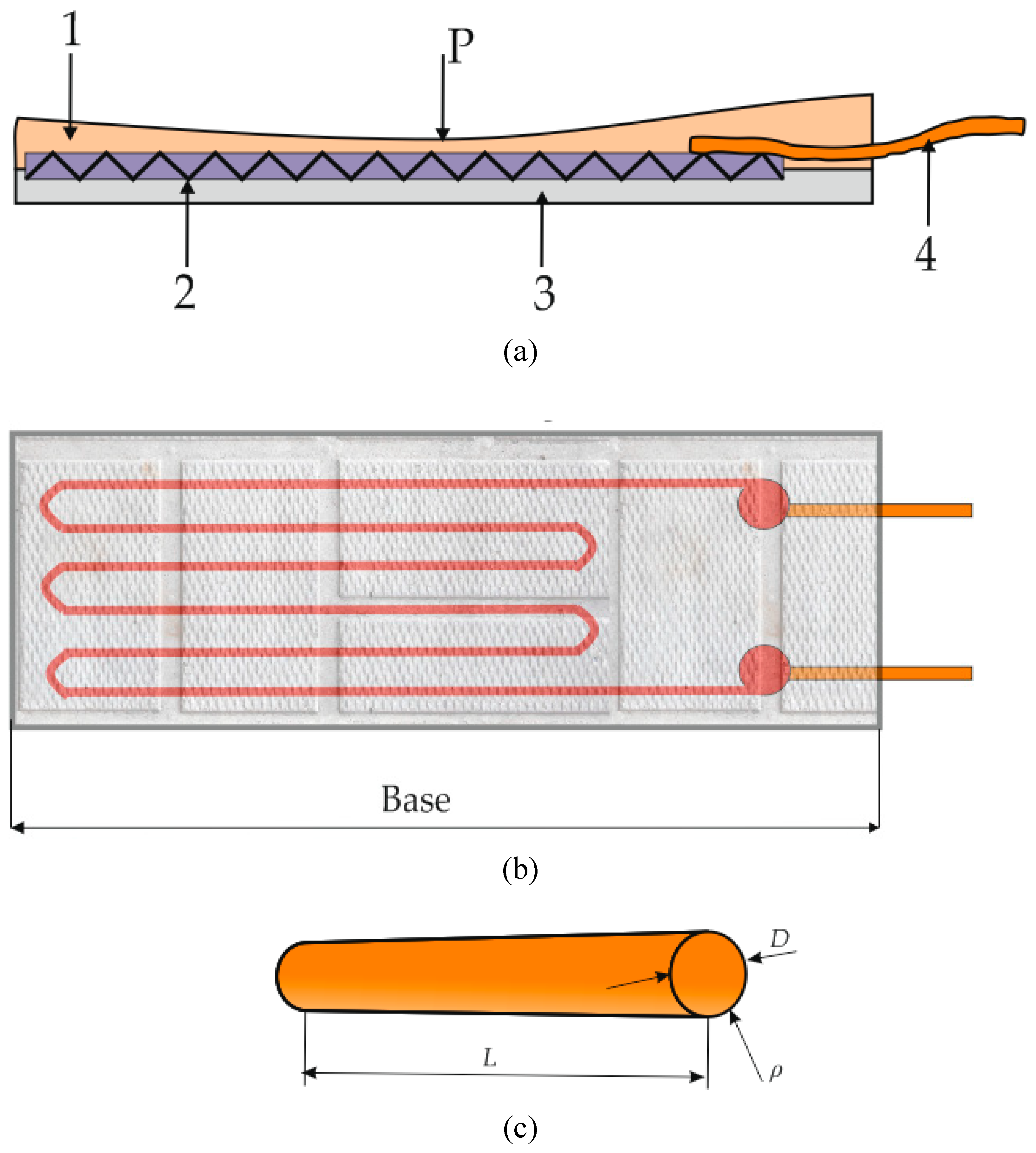
Figure 2.
Linear strain gauge: (a) – Working principle of strain gauge: 1 – wire grid; 2 ‒ paper; 3 ‒ contacts; (b) – Linear strain gauge (sample of the 60s).
Figure 2.
Linear strain gauge: (a) – Working principle of strain gauge: 1 – wire grid; 2 ‒ paper; 3 ‒ contacts; (b) – Linear strain gauge (sample of the 60s).
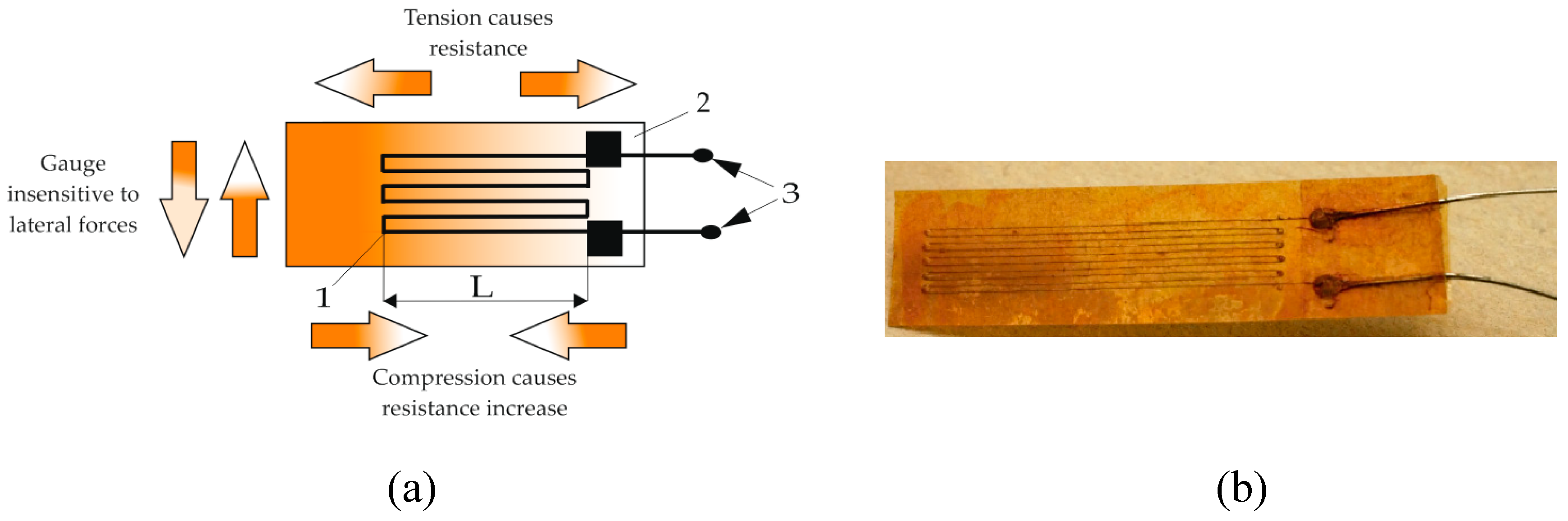
Figure 3.
Application of strain gauges: (a) ‒ wire gauge; (b) ‒ foil gauge.
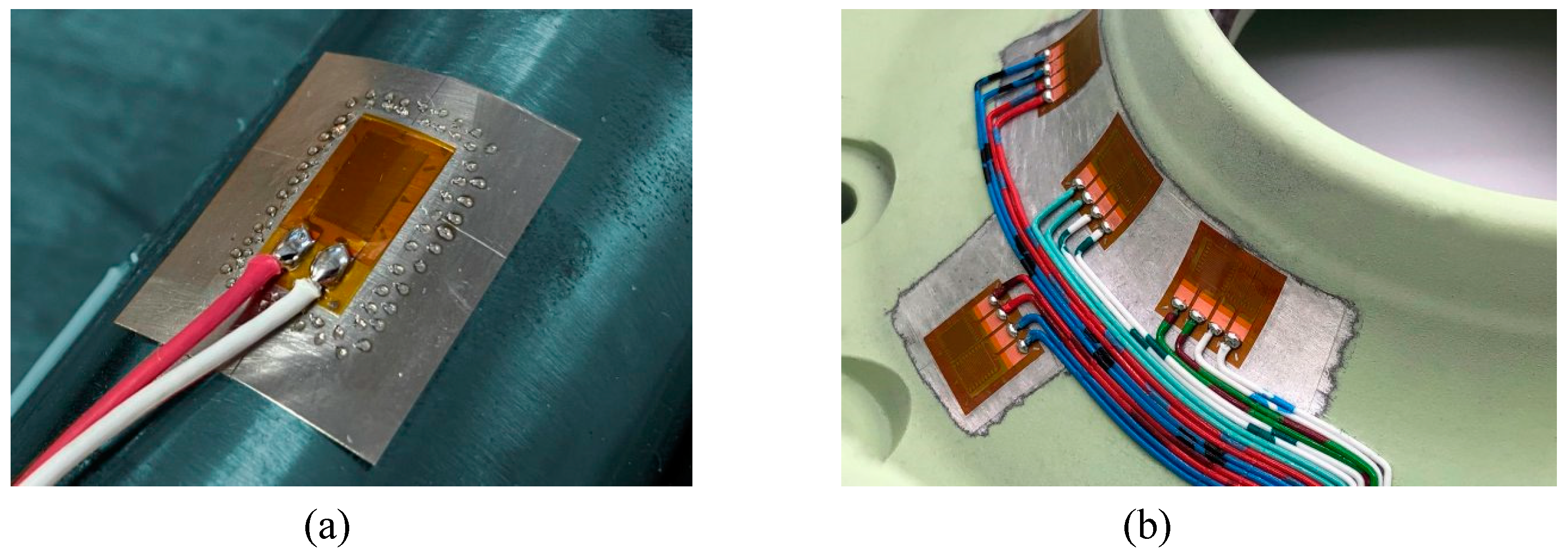
Figure 4.
Hot beverage filling machine.
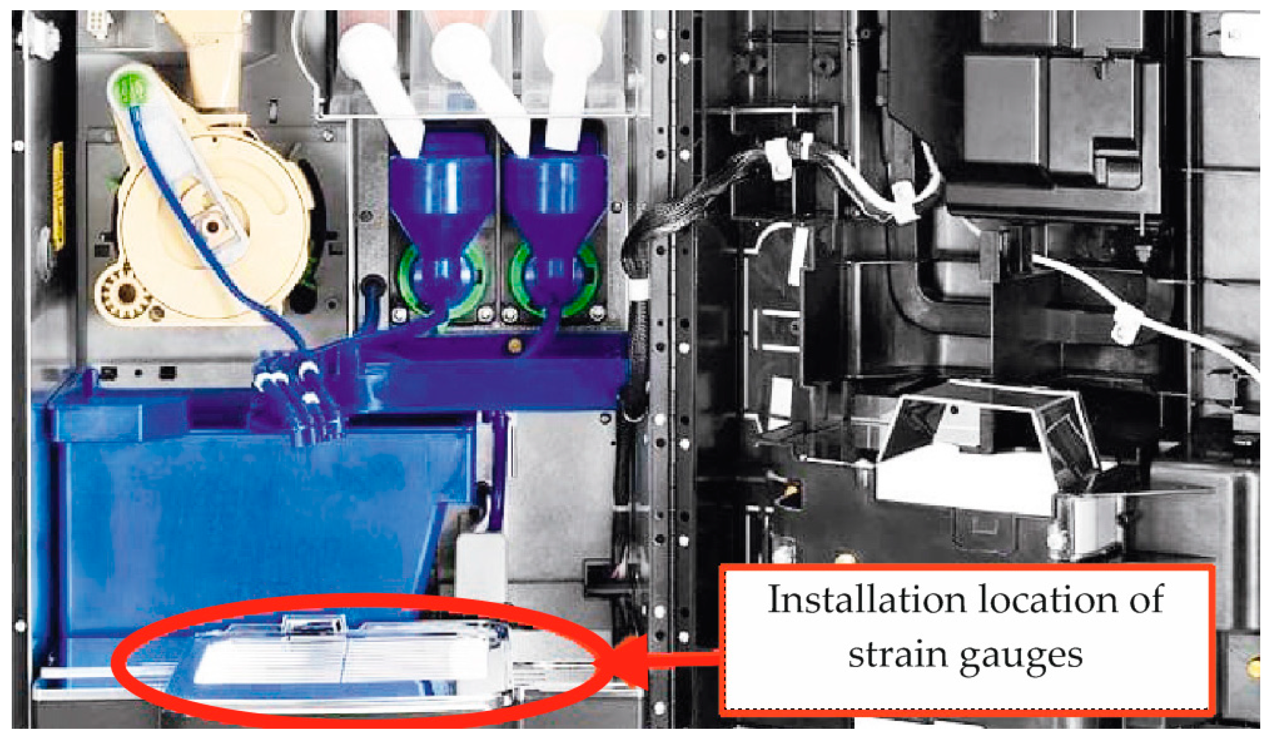
Figure 5.
Installation and mounting of column load cell ZSFY-A/-SS: 1 ‒ foundation; 2 ‒ lower baseplate; 3 ‒ duster; 4 ‒ upper cup; 5 ‒ upper baseplate; 6 ‒ loading platform; 7 ‒ M8 screw; 8 ‒ load cell; 9 ‒ lower cup; 10 ‒ eccentric.
Figure 5.
Installation and mounting of column load cell ZSFY-A/-SS: 1 ‒ foundation; 2 ‒ lower baseplate; 3 ‒ duster; 4 ‒ upper cup; 5 ‒ upper baseplate; 6 ‒ loading platform; 7 ‒ M8 screw; 8 ‒ load cell; 9 ‒ lower cup; 10 ‒ eccentric.
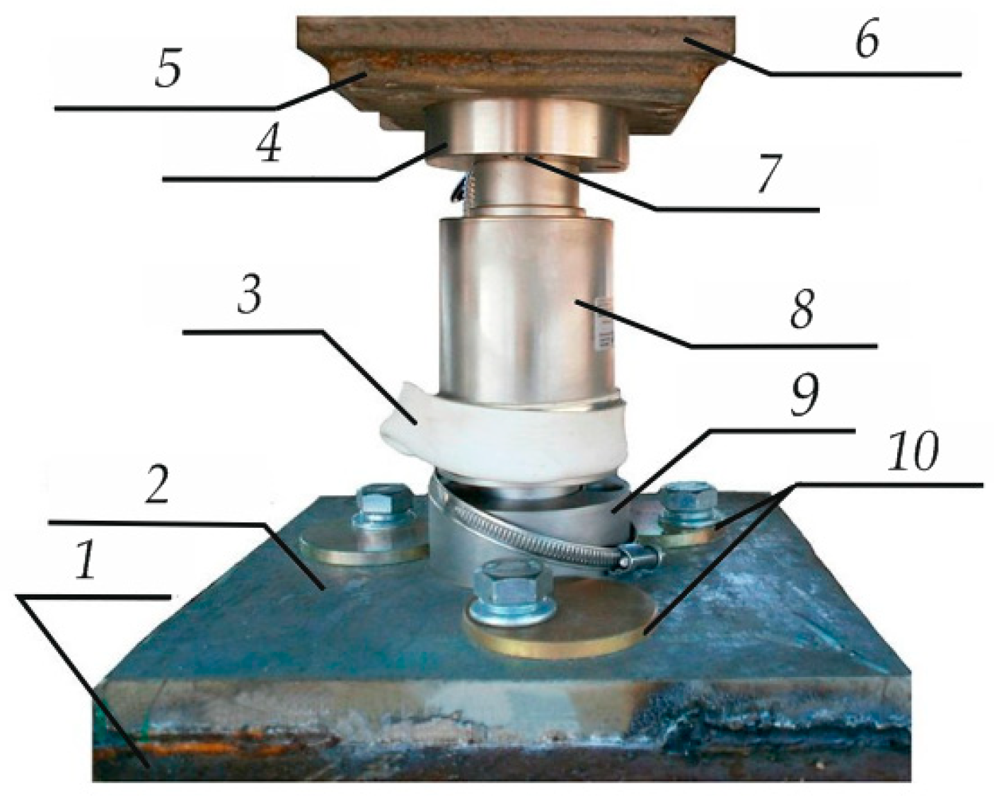
Figure 6.
Algorithm for selecting load cells for different applications.
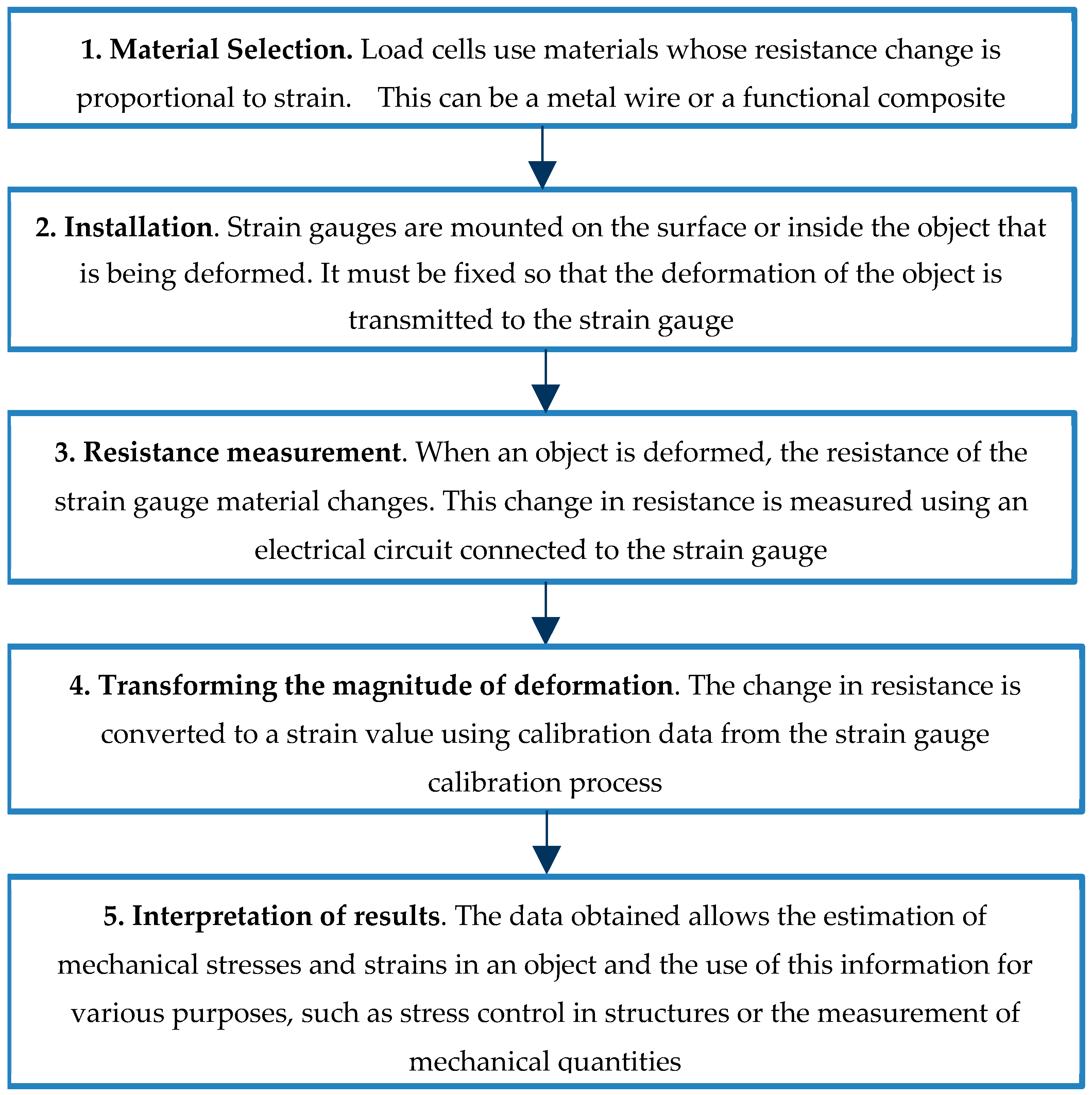
Figure 7.
Types of thermistors: (a) ‒ foil; (b) ‒ wire; (c) ‒ film.
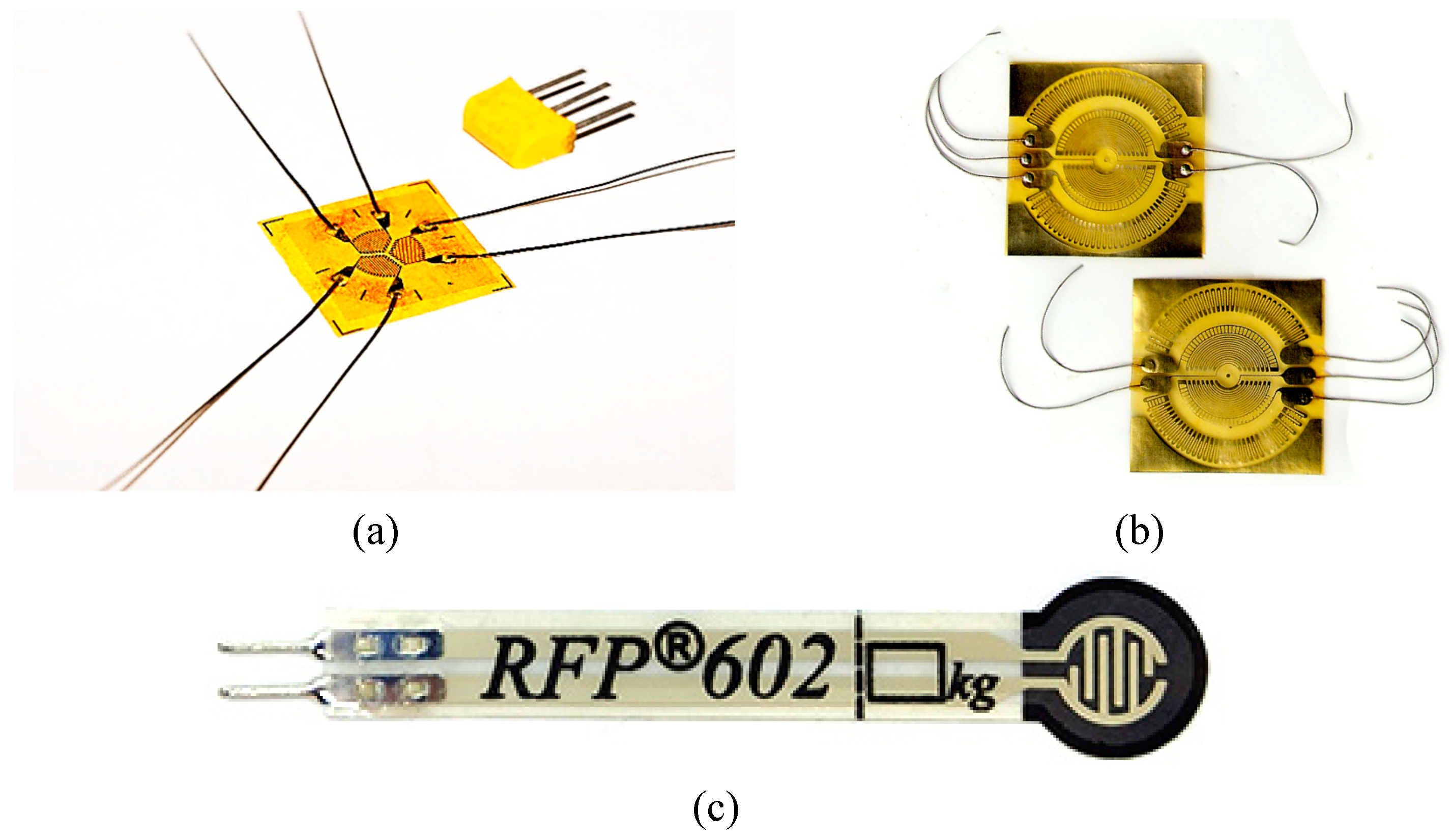
Figure 8.
Semiconductor strain gauge.
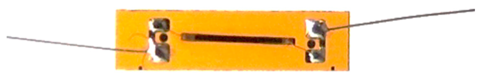
Figure 9.
Strain response of a high-temperature Pt thin-film thermistor at 700 °C, 5 cycles [54].
Figure 9.
Strain response of a high-temperature Pt thin-film thermistor at 700 °C, 5 cycles [54].
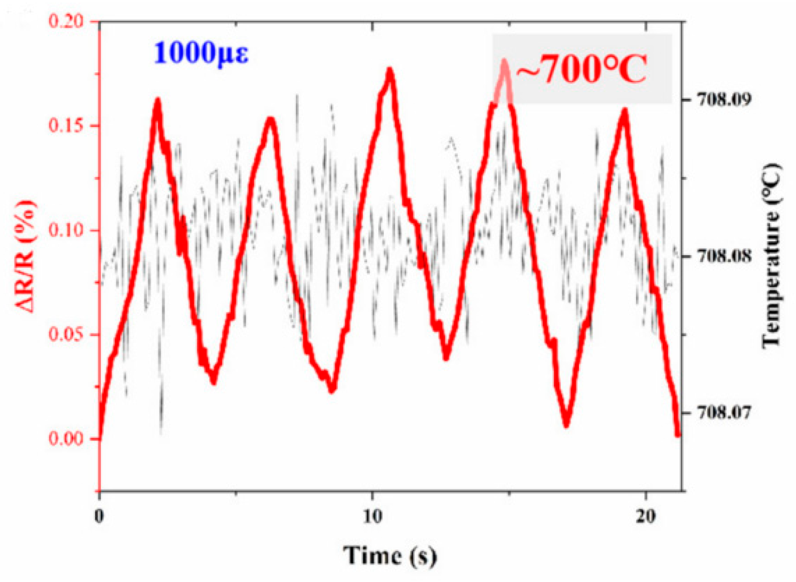
Figure 10.
Half-Bridge Circuit.
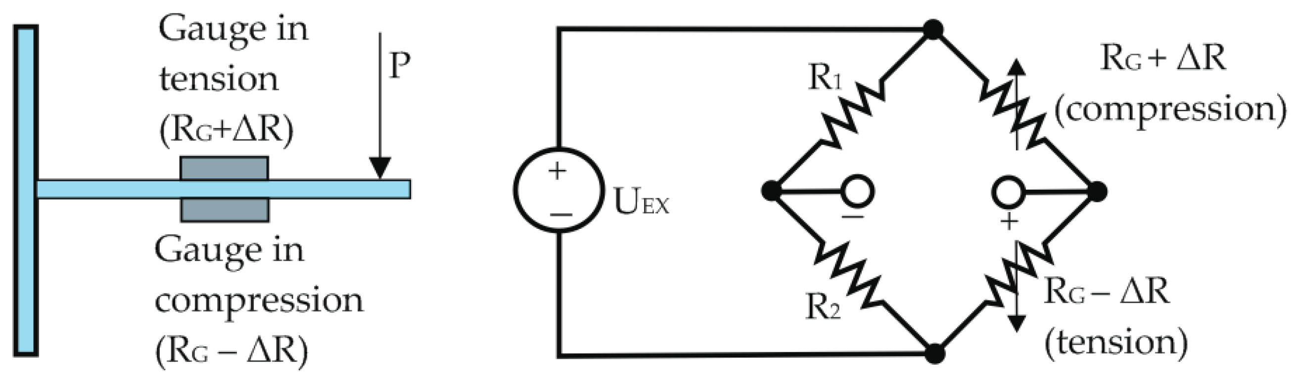
Figure 11.
Load cells by the shape of the load-bearing base: (a) – cantilever; (b) – cylindrical; (c) – S-shaped.
Figure 11.
Load cells by the shape of the load-bearing base: (a) – cantilever; (b) – cylindrical; (c) – S-shaped.
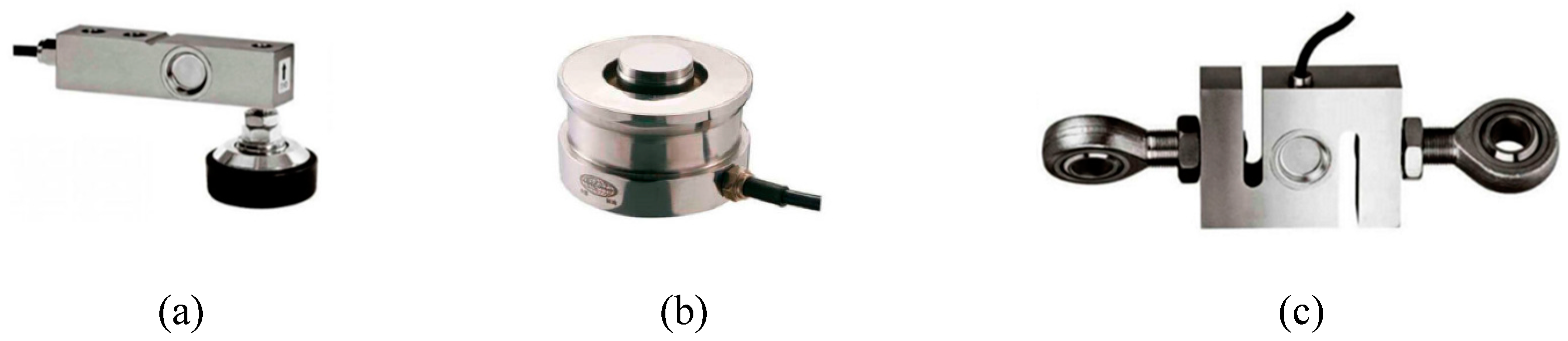
Figure 12.
Classification of strain gauges.
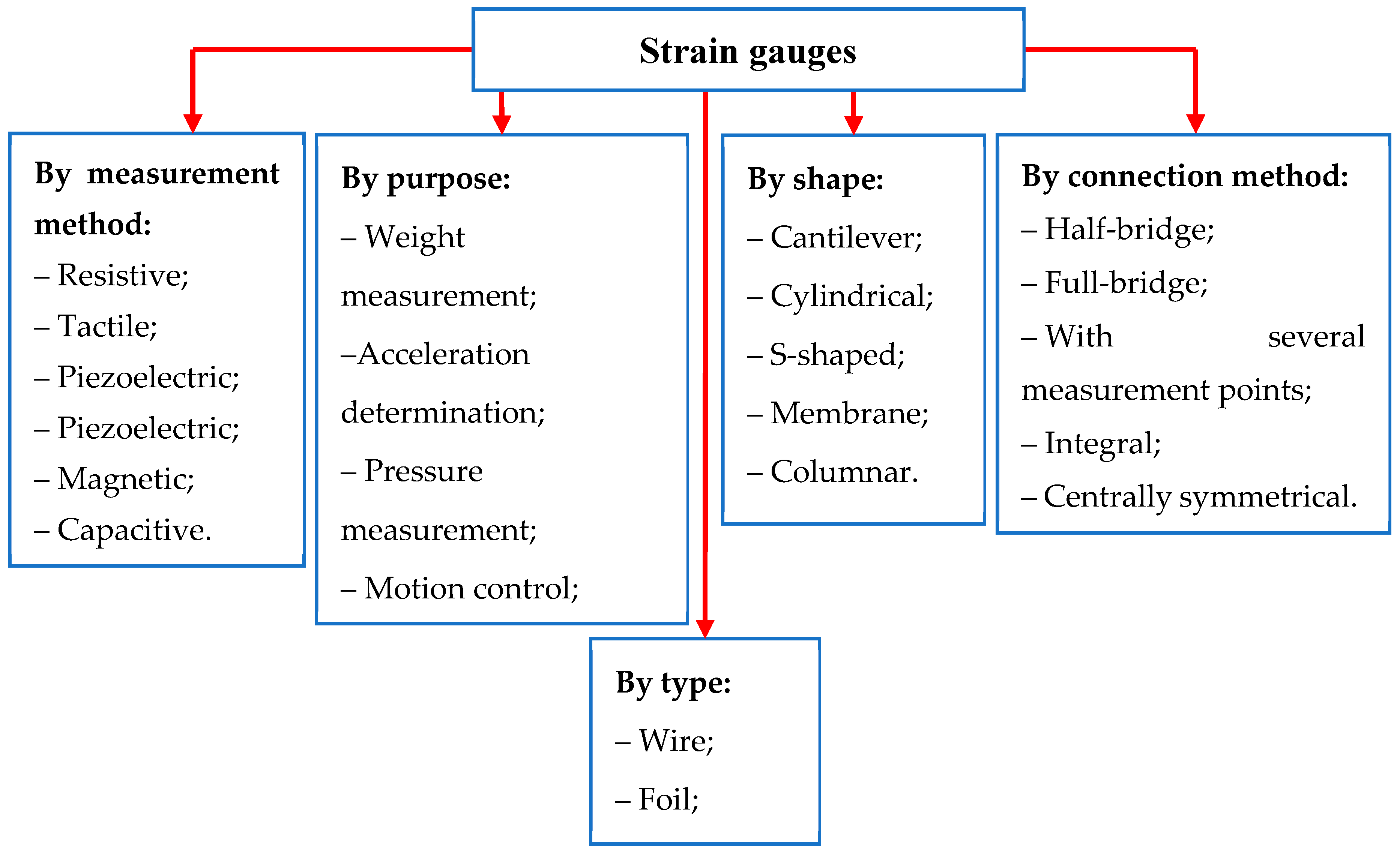
Figure 13.
Carbon nanostructures in different dimensions.
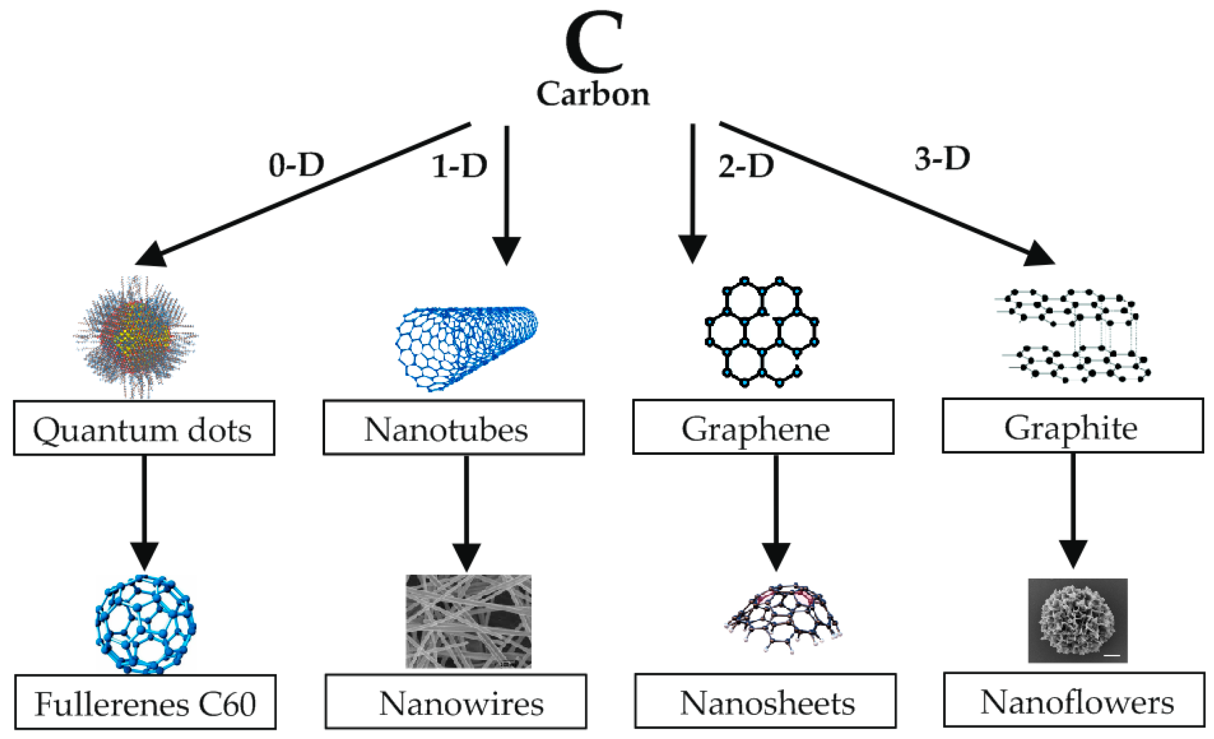
Figure 14.
Schematics of the MWCNT/PVA-based humidity sensor production process [86].
Figure 14.
Schematics of the MWCNT/PVA-based humidity sensor production process [86].
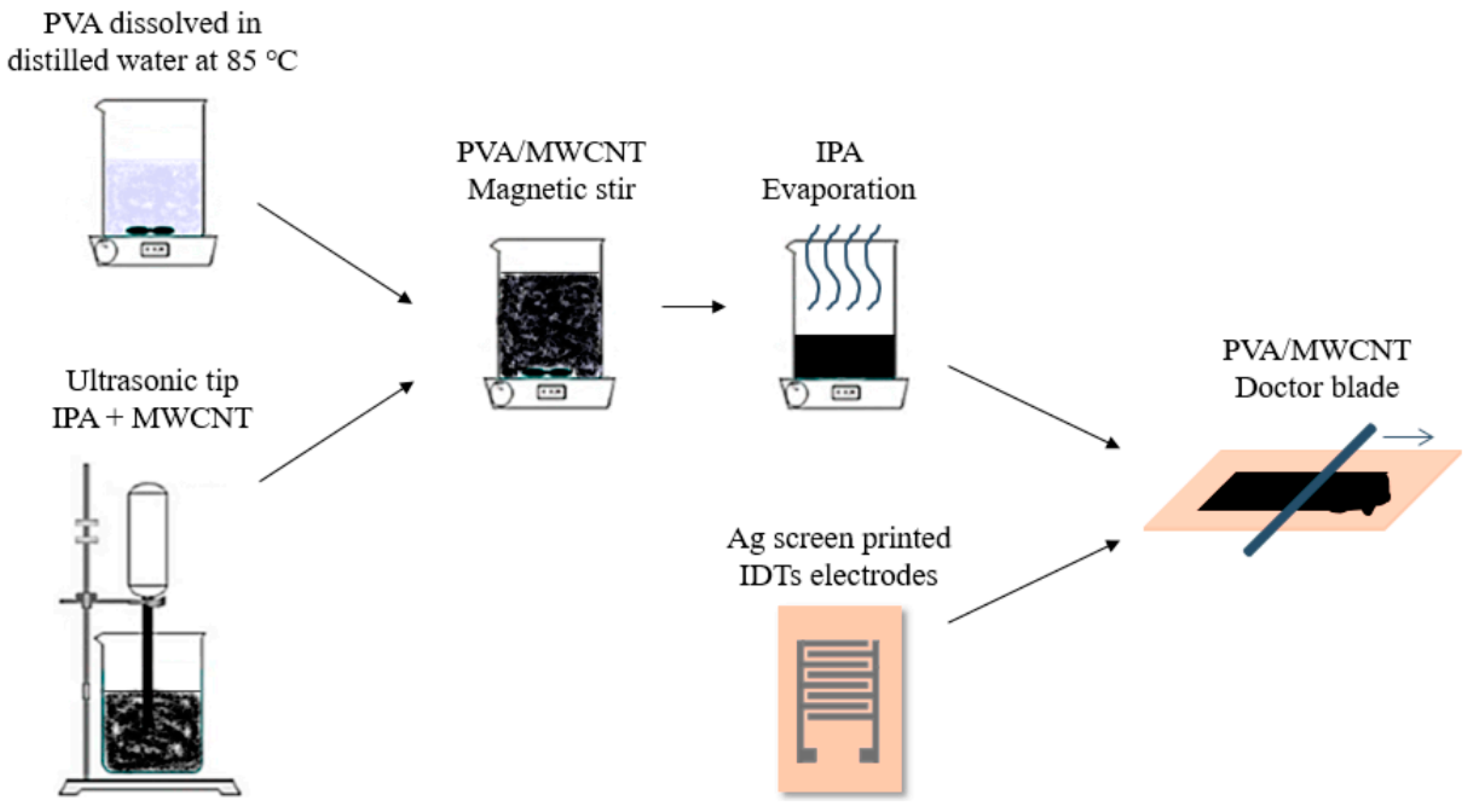
Figure 15.
Schematic for the alignment of CNTs in the composites by uniaxial stretching and network rearrangement [90].
Figure 15.
Schematic for the alignment of CNTs in the composites by uniaxial stretching and network rearrangement [90].
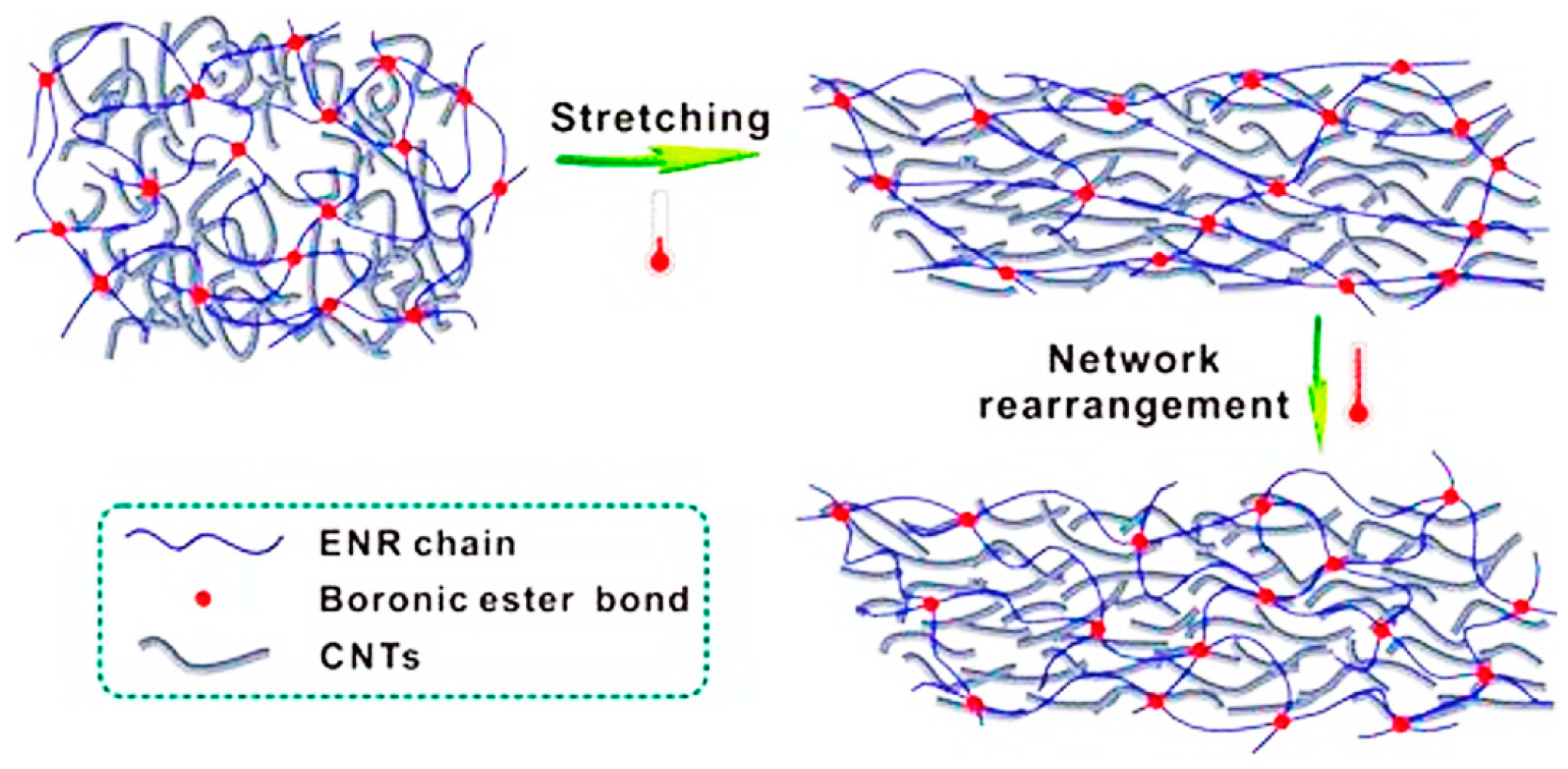
Figure 16.
(а) Schematical illustration of a strain sensor based on CPHs; and (b) the piezoresistivity mechanism of a PVA-PPy strain sensor when applying small strain [91].
Figure 16.
(а) Schematical illustration of a strain sensor based on CPHs; and (b) the piezoresistivity mechanism of a PVA-PPy strain sensor when applying small strain [91].
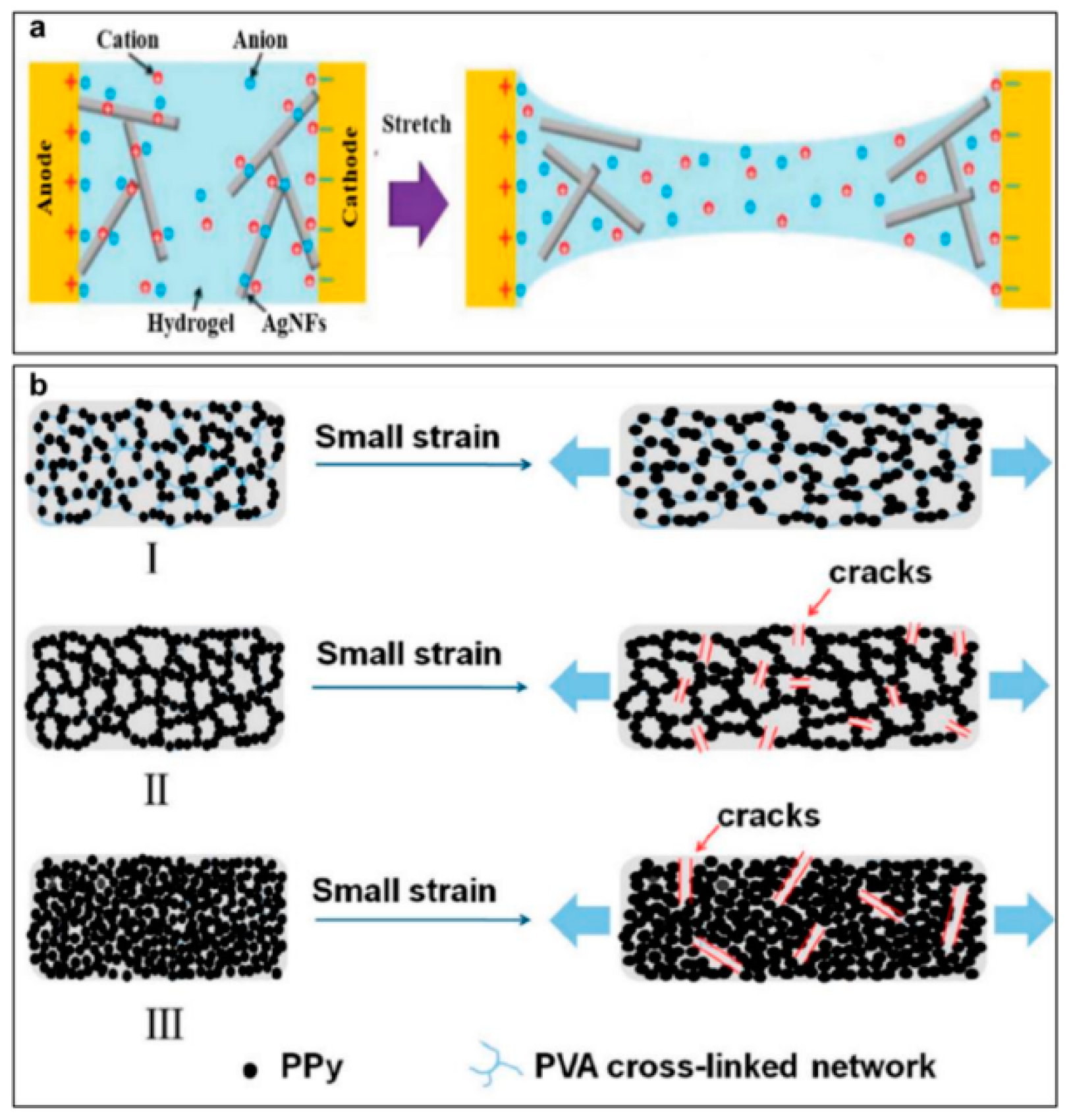
Figure 17.
Percolation process in conductive composites [71].
Figure 17.
Percolation process in conductive composites [71].
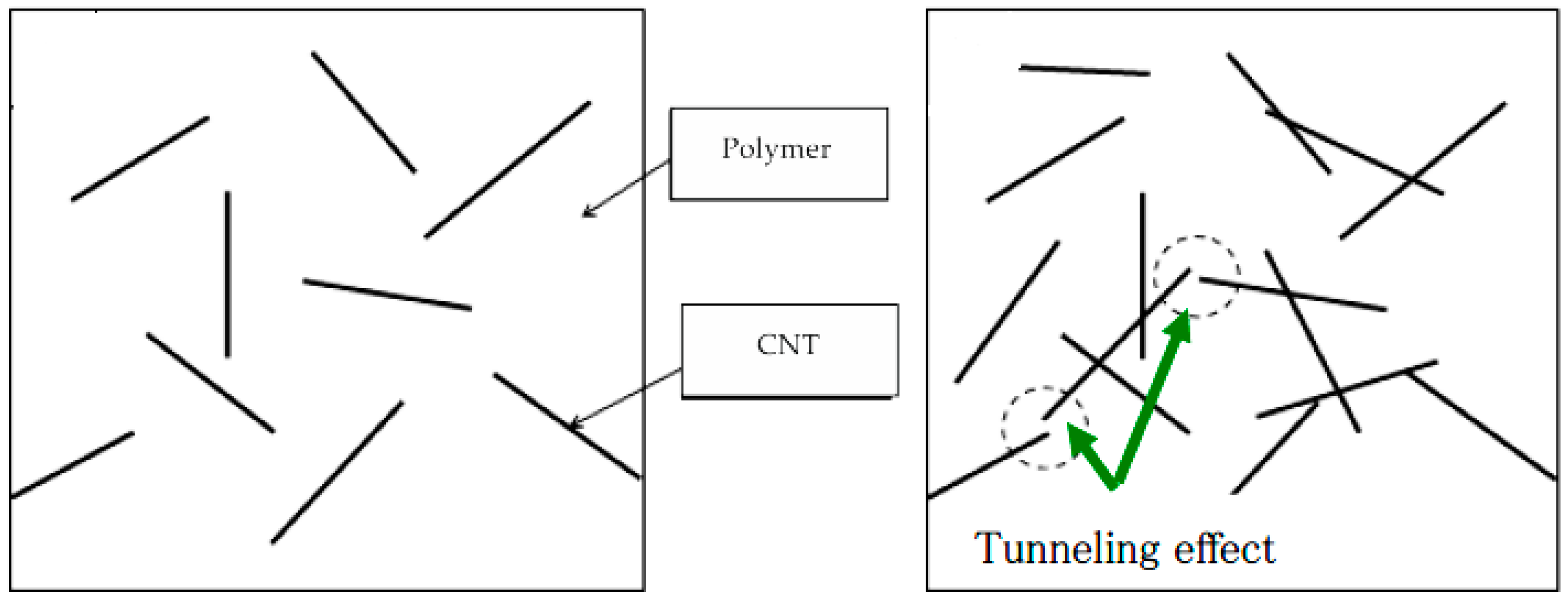

Table 1.
Advantages and disadvantages of strain gauge transducers.
| № | Advantages | Disadvantages |
|---|---|---|
| 1 | High Accuracy Measurement. Provides accurate and reliable force measurements, making them the ideal choice for applications where high accuracy is required | Limited in use. When used in environments with high temperatures and aggressive environments, special protection measures are required. |
| 2 | Wide measuring range. It is possible to measure both small and large forces, making them a versatile tool for a variety of applications | Minor change in sensor resistance (approximately 1%), requires signal amplification |
| 3 | Ease of use. Easy to install and maintain, they can be used in both fixed and portable installations | Sensitivity to environmental conditions. Dependence of sensitivity on ambient humidity and corrosion formation |
| 4 | Durability. Tensodactyls are made of durable materials, giving them a long service life | Accuracy. Decrease in measurement accuracy under vibration conditions |
Table 2.
Application areas of strain gauges.
| Application Area | Measurement | Purpose |
|---|---|---|
| Mechanical engineering | Control of structural strength | Determination of stresses in machine parts and mechanisms to prevent destruction |
| Vibration monitoring | Analysis of vibration loads on structural elements | |
| Study of fatigue characteristics of materials | Determination of the service life of parts under cyclic loads | |
| Quality control of welded seams | Evaluation of the strength of welded joints | |
| Construction | Stress control in structures | Determination of stresses in reinforced concrete structures, bridges, buildings |
| Monitoring of foundation deformations | Control of settlement of buildings and structures | |
| Study of the behavior of materials under various loads | Determination of deformation characteristics of building materials | |
| Aviation and space industry | Strength testing of aircraft, including drones | Determination of stresses in structural elements of aircraft and rockets |
| Study of the behavior of materials under extreme conditions | Study of the behavior of materials at high temperatures, pressures and vibrations | |
| Automotive industry | Body and suspension strength control | Determination of stresses in elements of the car body and suspension |
| Development of new materials | Research of new materials for the automotive industry | |
| Medicine | Measurement of biomechanical parameters | Study of joint movement, muscle strength |
| Creation of prostheses and orthoses | Load control on prostheses and orthoses | |
| Geology and Geophysics | Measuring stresses in rocks | Determination of the state of rock masses for the prediction of rockfalls and landslides |
| Monitoring seismic activity | Study of deformations of the earth's crust |
Table 3.
materials for foil load cells.
| № | Materials | |
|---|---|---|
| Load Cell | Substrate | |
| 1 | Constantanium foil, constantanium wire | For limited use cyanoacryalate; For long life, epoxy or phenolic glass; Polyimide; Paper, Bakelite |
| 2 | Nichrome foil, nichrome wire | Phenolic glass; Removable Teflon glass strip |
| 3 | Isoelastic wire | Bakelite, paper |
| 4 | Dynaloy foil | Polyimide, polyimide glass |
| 5 | Stabiloy foil, Stabiloy wire | Polyimide, phenolic glass; Removable Teflon glass strip |
| 6 | Platinum-tungsten wire | Phenolic glass; Removable Teflon glass strip |
Table 4.
Materials for load cells.
| № | Sensitive Material | K | Substrate | Ref. |
|---|---|---|---|---|
| 1 | Me=W,Ti и Ni (film) | >10 | DLC | [58] |
| 2 | Ag-ITO | 4 – 7 | DLC | [58] |
| 3 | TiAlNxO | 2.2–2.5 | Sapphire | [59] |
| 4 | AlN/Pt | ≤4.7 | Al2O3 | [60] |
| 5 | Pt/SiO2 | 18 | Si-wafers | [61] |
| 6 | Invar36 | 2.5 – 4.5 | Microslides | [62] |
| 7 | NiCr | 2.5 | Ni-base superalloy | [63] |
| 8 | Pt | 1.7–1.9 | Ni-base superalloy | [54] |
| 9 | Pt | 1.9–2.5 | Sapphire | [64] |
| 10 | MXene/MWCNTs | 646 | PDMS | [4] |
| 11 | MXene | 178 | PDMS | [65] |
| 12 | MXene | 228 | polyurethane | [66] |
| 13 | CNTs | 7.22 | PDMS | [67] |
| 14 | MWCNTs | 9 | PDMS | [68] |
| 15 | MWCNTs | 181.36 | Graphene platelets | [69] |
| 16 | MWCNTs | 4.3 | PDMS | [70] |
| 17 | MWCNTs | 513 | PDMS | [71] |
| 18 | MWCNTs | 22 | TPU | [72] |
| 19 | MWCNTs | 1 – 1.5 | Silicone polymer | [73] |
| 20 | MWCNTs | 34.38 | Silicone rubber | [74] |
| 21 | MWCNTs | 43.4 | Graphite films | [75] |
| 22 | MWCNTs | 2800 | TPU | [76] |
| 23 | MWCNTs | 12.15 | PDMS | [77] |
| 24 | MWCNTs | 2.4 | Eraser | [78] |
| 25 | MWCNTs | 4.5 | PDMS | [79] |
| 26 | MWCNTs | 513 | PDMS | [80] |
* PDMS ‒ Flexible polydimethylsiloxane (PDMS) substrate; TPU ‒ Thermoplastic polyurethane substrate.
Table 5.
Comparative table of characteristics of strain gauges.
| Characteristic | Wire | Foil | Film |
|---|---|---|---|
| Accuracy | Average | High | Average |
| Linearity of characteristic | Average | High | Low |
| Sensitivity | High | Average | Very high |
| Strength | High | Low | Average |
| Stability of characteristics | Average | High | High |
| Cost | Average | Average | High |
| Dimensions | Large | Small | Very small |
Disclaimer/Publisher’s Note: The statements, opinions and data contained in all publications are solely those of the individual author(s) and contributor(s) and not of MDPI and/or the editor(s). MDPI and/or the editor(s) disclaim responsibility for any injury to people or property resulting from any ideas, methods, instructions or products referred to in the content. |
© 2024 by the authors. Licensee MDPI, Basel, Switzerland. This article is an open access article distributed under the terms and conditions of the Creative Commons Attribution (CC BY) license (http://creativecommons.org/licenses/by/4.0/).
Copyright: This open access article is published under a Creative Commons CC BY 4.0 license, which permit the free download, distribution, and reuse, provided that the author and preprint are cited in any reuse.


