Submitted:
07 November 2024
Posted:
08 November 2024
You are already at the latest version
Abstract
With the rise of autonomous systems, the need for precision in navigating uncertain environments has become paramount. Unmanned vehicles in particular require accurate detection and spatial positioning of obstacles to ensure safe and efficient navigation. This research introduces a sensor-fusion based system that integrates an ESP-32 camera module and an ultrasonic sensor to detect objects and calculate their relative position to the vehicle in an average of 715 milliseconds. The object detection pipeline utilizes the Yolov8 object detection algorithm to detect and classify objects in the camera’s field of view. Combining the pinhole camera formula and Yolov8 bounding box, an equation is formulated to compute the exact spatial coordinates of the object. The system was validated through a series of experiments involving different object types at varying distances, resulting in a dataset of 397 instances with a total of 3176 values. The solution achieved a spatial detection accuracy of 89%, demonstrating its potential for reliable obstacle avoidance in unmanned vehicles.
Keywords:
YOLO
; sensor fusion
; field of view
; object detection
; ultrasonic sensor
1. Introduction
From unmanned drones to household robotic systems, spatial detection and obstacle avoidance have a special role in ensuring efficient navigation in complex environments. Accurate object detection and spatial positioning are crucial for unmanned vehicles as they navigate and interact with constantly changing surroundings.
These capabilities enable key functionalities like obstacle avoidance, path planning, and interaction with the environment [1]. The first step towards recognition of the environment is object detection, and with the rise of artificial intelligence numerous algorithms have been developed to tackle this challenge efficiently. Amongst these, Yolov8 stands out due to its remarkable speed, accuracy and ease of configuration[2]. This research takes advantage of YOLOv8’s computational efficiency by processing images from the ESP32-Cam to achieve robust object detection.
While cameras excel at object detection, estimating depth from a single image is quite challenging and results in noisy estimates even under complex deep neural network models[3]. This dismisses the possibility of achieving accurate real-time spatial positioning from just one camera. There exist several conventional approaches to estimate depth of objects and they include are LIDAR, RADAR, ultrasonic sensors and the stereo-cameras[4], and each has their benefits and limitations. LIDAR provides excellent accuracy but is costly, RADAR performs reliably in adverse weather but offers lower resolution, and although cameras capture high-resolution images, they struggle in low-light conditions. Ultrasonic sensors, though cost-effective, are limited to measurements, and suffer in precision at longer distances[4].
Approaches relying solely on cameras or individual sensors often fall short in terms of precision and computational efficiency[4]. Monocular vision systems, for example, face challenges in accurately estimating depth[5], while sensor-based methods may not offer the necessary resolution for precise localization[4].
This work suggests a unique method that combines ultrasonic distance measurements with results from the YOLOv8 algorithm to overcome the individual challenges of both the camera and the ultrasonic sensor. With a mathematical equation which incorporates focal length into the information from the YOLOv8 model, a PC computes calculates the spatial coordinates in relation to the source.
This integrated approach, implemented on a low-cost and adaptable hardware, presents a promising solution for enhancing perception and navigation in unmanned vehicles across various applications.
2. Related Work
The detection and spatial positioning of objects revolves around three key components: Image object detection, spatial positioning and sensor fusion. These three elements form the basis of for the research on real-time spatial detection and hence the core of this project.
2.1. Object Detection
Object detection is fundamental for enabling unmanned vehicles to perceive their environment and identify distinct features within an image. Deep learning, which has effective feature representation capabilities, has become a leading approach in image object detection research[6]. Current methods of object detection in deep learning can be broadly categorized into two strategies: convolutional neural networks (CNNs) and transformer-based models[7].
Within CNN-based methods, there exist two primary categories, which are the region proposal-based detection (two-stage algorithms) and the regression-based detection (one-stage algorithms). Region proposal methods detect objects using a two-step process. First, bounding boxes are generated around potential objects, then the bounded images are classified. Algorithms like the R-CNN[8] and Faster R-CNN[9] make use of the region proposal-based detection. These methods benefit from combining shallow and deep feature maps to improve detection accuracy. On the other hand, regression-based detection methods, such as SSD[10] and the YOLO series[11], perform object localization and classification in a single step, streamlining computation and improving speed.
Transformer-based model uses a self-attention mechanism to handle sequence-to-sequence tasks[7]. Using an encoder-decoder structure, demonstrate strong performance in capturing long-range dependencies and modeling object features. Popular usage of this model is found in algorithms like MMViT [12] and Reformer [13]. While Transformers like Vision Transformers (ViT)[7] have made significant strides in computer vision, they are often computationally heavier than CNNs, particularly in real-time applications[14].
Because of the limitation of the transformer model, the YOLO series has emerged as a preferred choice for this project. Due to its excellent balance of generalization, processing speed, lightweight architecture, and scalability[14]. Earlier versions of the You Only Look Once family, such as YOLOv3 and YOLOv4, marked significant progress in real-time object detection. The recent iteration, YOLOv8, outperforms its predecessors[15] and competing models in both speed and accuracy, making it highly suitable for real-time applications in unmanned vehicles.
2.2. Spatial Positioning
Spatial positioning is the process of determining an object exact placement in a three-dimensional plane with respect to a reference point[16]. Accurate spatial positioning of obstacles around them allows unmanned vehicles to perceive their environment. There are three approaches to spatial positioning and they are: Visual, non-visual and sensor fusion [4].
Visual positioning methods perceive their environment through images or a video stream. There exist various visual positioning methos and they are monocular visual systems and Stereo vision systems[17]. Monocular systems make use of a single camera to capture their surroundings. Single camera lacks depth perception so they have to undergo image processing to extract features like edges and curves [18]. While there exist many filtering algorithms and AI models to perceive the surrounding from a single image [19], the process is computationally expensive and results in delays in the image processing[17]. Stereo systems on the other hand make use of two cameras placed at a distance apart. They outperform the monocular systems in sensing depth however, they have a high computational cost and require a more complex hardware architecture[20]. This limits their application in unmanned vehicles especially smaller models that might have space and computational limitations. A general limitation for all visual positioning sensors is their poor performance in low light conditions, hence limiting their usage in
Unlike the Visual positioning methods, non-visual positioning sensors have the advantage of operating in the low light or the absence of light[21]. Some examples of such sensors are LIDAR, RADAR and Ultrasonic sensors. Light Detection and Raging (LIDAR) uses laser beams to measure distance of objects by generating pulses and estimating the time it takes the pulses to be reflected back to the source. This is an efficient way of creating 3D maps of the surrounding, however, their high computation requirement limits their usage in small unmanned systems[4]. Radio detection and Ranging (Radar) has been the standard adopted in the field of aviation. It performs effectively in adverse weather conditions, meanwhile, previous studies [22] have shown that radar technology can be computationally challenging and hence would pose problems to small unmanned vehicles. Ultrasonic sensors on the other hand are cheap lightweight and less computationally [4] demanding, but they are limited by their range of measurement which falls within a few meters.
2.3. Sensor Fusion
Spatial positioning solves the limitation of both visual (active) or nonvisual (passive) sensors by combining data from both sources. Passive sensors, such as cameras, gather information by capturing data from the environment, while active sensors emit energy, such as waves, and then detect the reflected signals. Combining both types of sensors, gives rise to the technique known as sensor fusion. This technique enhances accuracy and reliability in spatial positioning by leveraging the strengths of each sensor type[4].
This approach capitalizes on the strengths of multiple sensors to improve perception and decision-making processes in unmanned systems. Several studies have demonstrated the effectiveness of sensor fusion for obstacle avoidance and spatial positioning. One study integrates an ultrasonic sensor with an infrared range finder to enhance obstacle detection[23]. At the same time, another explores the combination of a monocular camera with millimeter-wave radar to improve depth perception[24]. Similarly, an environmental mapping system utilizes 2D LiDAR and a camera to achieve accurate spatial awareness[25]. These studies underscore the value of combining different sensing modalities, as fusing data from complementary sensors can significantly enhance the accuracy and reliability of the results. The integration of these diverse sensors confirms the critical role of sensor fusion in developing robust perception systems for unmanned vehicles.
This project utilizes ultrasonic sensors in conjunction with a single camera for spatial positioning of objects around the unmanned vehicle. By fusing results from the YOLOv8 algorithm with data from the Ultrasonic sensor, this project doesn’t just detect objects in their path, but calculates the actual positions of surrounding objects within the field of view of the camera.
System Architecture
3.1. Overview of the System
The system comprises an ESP32-CAM module, an ESP8266 microcontroller, and ultrasonic sensors, which collectively gather essential data for processing the spatial coordinates of detected obstacles. The block diagram illustrating the system architecture is provided below.
Figure 1.
System diagram: This figure shows the flow of data from one unit of the system to another.
Figure 1.
System diagram: This figure shows the flow of data from one unit of the system to another.
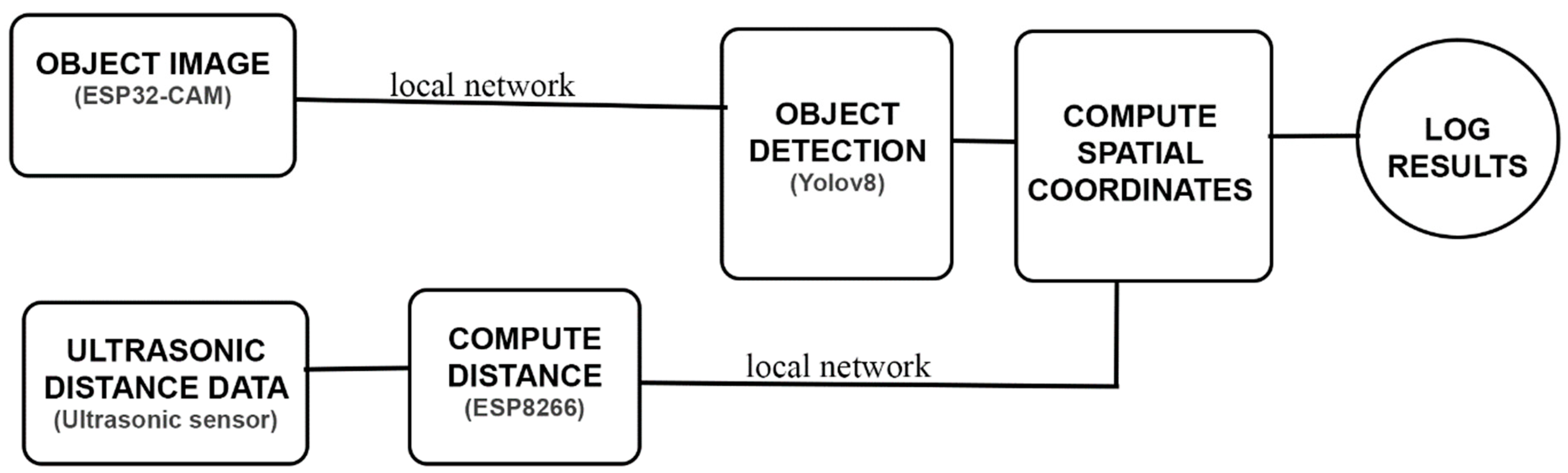
Both the ESP32-CAM and ultrasonic sensors operate concurrently to capture visual and distance data. The video data from the ESP32-CAM is divided into individual frames, which are made available on the local WIFI network. Meanwhile, the ultrasonic sensor data is processed by the ESP8266 microcontroller, which converts the sensor readings into distance values in centimeters. These distance measurements are similarly transmitted over the local WIFI network. This configuration enables any device connected to this network to access video frames and distance measurements in real time.
A computer system retrieves the video frames, which are processed using the YOLOv8 algorithm to generate bounding boxes around detected objects. This output, along with the distance measurements from the ultrasonic sensor, is then fed into a mathematical model; this model is evaluated in Section 3. The model combines the bounding box data and distance measurements to calculate the spatial positions of objects within the camera’s field of view.
3.2. Hardware Components
The system comprises the following hardware components:
- ESP8266 microcontroller
- ESP32-CAM Module
- Ultrasonic sensor
3.2.1. ESP32-CAM Module
The ESP32-CAM is a compact yet powerful development board that integrates an ESP32-S microcontroller with a camera module, making it suitable for visual data capture in embedded applications. This module is selected for its low cost, networking capability, and versatility in capturing real-time images and video streams. The ESP32-CAM is equipped with an ESP32-S chip which includes dual-core processors with a clock speed of up to 240 MHz. It supports both Wi-Fi and Bluetooth connectivity, which facilitates wireless communication. The module is fitted with an OV2640 camera sensor with a resolution of 2 megapixel[26], which provides sufficient detail for object detection tasks. The ESP32-CAM is power efficient and operates within 3.3 volts to 5 volts, thus making it an ideal choice for devices requiring strict energy consideration. Its small form factor allows it to integrate easily into unmanned vehicles with size and weight constraints.
Despite its many functions, the ESP32-CAM is limited in its support for input and output peripherals. Since most of its GPIO (General Purpose Input/Output) pins are used controlling the camera and memory card reader, it becomes difficult to interface directly with additional sensors like the ultrasonic sensor. Also, power supplied to the module is largely consumed by the camera, which restricts its ability to power other peripherals.
3.2.2. ESP8266 Microcontroller
The ESP8266 microcontroller serves as a complementary component in this system. It manages the ultrasonic sensor and converts raw data into distance measurements. This microcontroller has support for both Wi-Fi and Bluetooth communication and has an operating voltage between 3.3 volts and 5 volts. The ESP8266 has the ability to support various input and output sensors due to its sufficient GPIO pins. This makes it a suitable choice to handle the ultrasonic sensor.
3.2.3. Ultrasonic Sensor
The ultrasonic sensor measures distance from the sensor to an object with the use of sound waves. It emits ultrasonic waves and measures the time it takes for the sound to be reflected back. This project makes use of the SRF05 sensor which has a working range between 2cm to 450cm[27]. It operates by receiving a 10micro second pulse, this triggers the SRF05 to emit 8 cycles bust of 40khz after which the echo line is raised and the sensor listens for an echo. The echo line is lowered If an echo signal is received but if the echo is not received in 30milliseconds the line is dropped allowing the sensor to perform another measurement.
This echo line is a pulse whose width is proportional to the distance between the object and the sensor[27]. The timing diagram for this operation is shown below.
Figure 2.
Timing Diagram for SRF05 [26].
Figure 2.
Timing Diagram for SRF05 [26].
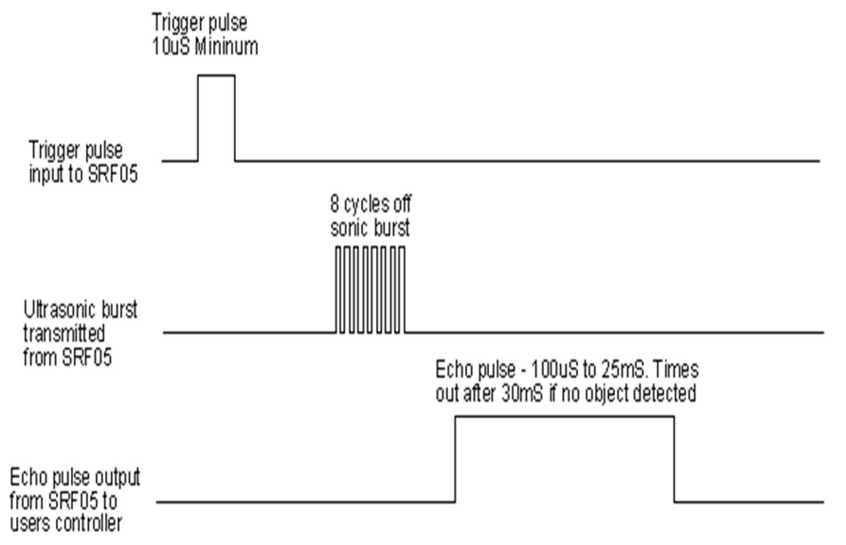
After each measurement a 50millisecond delay is recommended before the next trigger. This is to prevent ultrasonic beep[27] – that is noise from returning echo.
3.3. Software Components
3.3.1. YOLOv8
You Only Look Once (YOLO) is a state-of-the-art, real-time object detection algorithm widely used for tasks requiring high-speed and accurate object recognition. YOLOv8, an iteration of the YOLO family, released in January 2023[2] incorporates several optimizations that make it a powerful tool for real-time object detection systems. YOLOv8 excels in detecting objects within a visual frame by creating bounding boxes around recognized objects. In this system, video frames captured by the ESP32-CAM are passed through a server running YOLOv8. The algorithm processes these frames, identifying objects in real-time with minimal computational overhead.
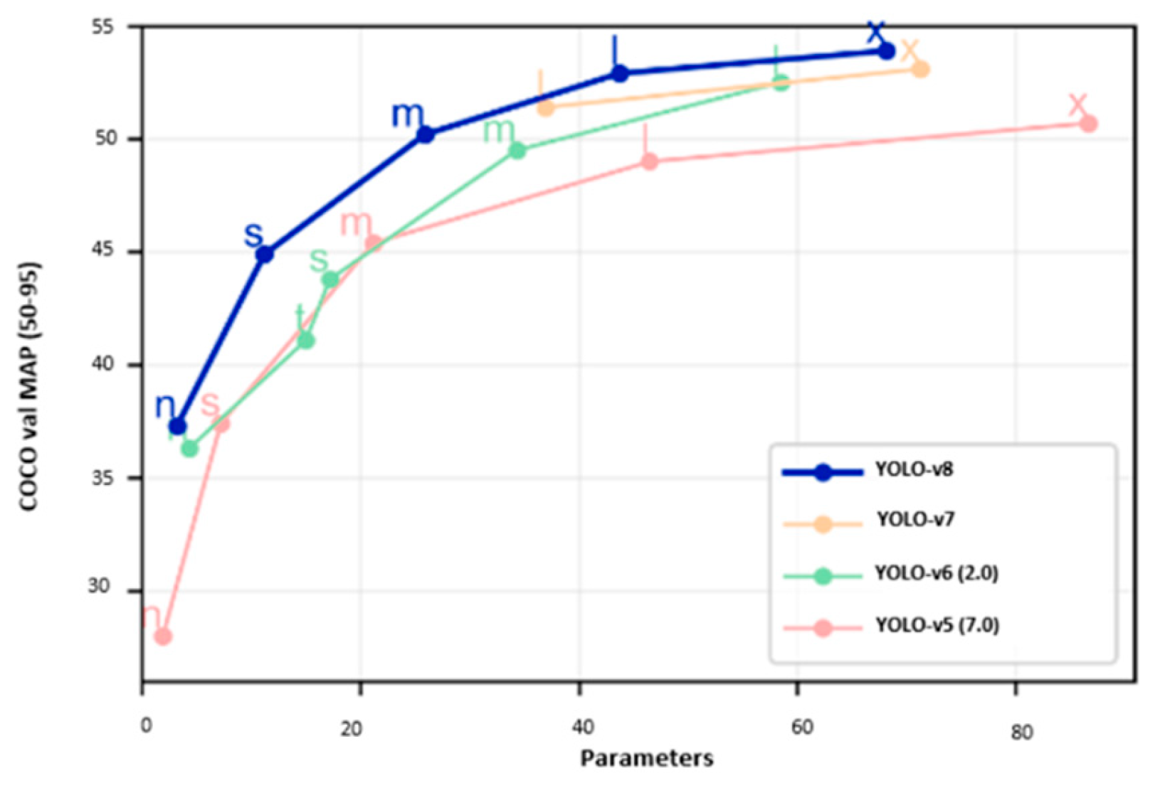
One of the key strengths of YOLOv8 is its balance between detection speed and accuracy. YOLOv8 is designed to provide fast object detection and processing frames at high speed without sacrificing precision.
Figure 3.
Performance evaluation of yolov8 against other yolo models on the coco dataset[2].
Figure 3.
Performance evaluation of yolov8 against other yolo models on the coco dataset[2].
While the YOLOv8 algorithm is not directly deployed on the ESP32-CAM due to the size and computational limitations of the ESP32-CAM, the video data is transmitted to a server for processing. This distributed architecture allows the system to harness the power of YOLOv8 without overburdening the limited resources of the ESP32-CAM. The bounding box outputs generated by YOLOv8 are then combined with distance data from the ultrasonic sensor to calculate the spatial coordinates of objects in the vehicle’s environment.
3.3.2. Arduino IDE
The Arduino Integrated Development Environment (IDE) is a user-friendly platform used for writing, compiling, and uploading code to microcontrollers like the ESP32 and ESP8266. It plays a pivotal role in this project by providing the necessary tools to support debugging and the upload of codes to both modules. The Arduino IDE supports a wide range of libraries, such as the ESP32-CAM camera library and the ultrasonic sensor library, which simplify the development process and allow for quick prototyping and testing of the system.
Mathematical Equations
4.1. Focal Length and Camera
A key aspect of determining the size and position of actual objects from image data involves understanding the relationship between the captured image, the camera properties and the distance from the object to the camera. This process is governed by the pinhole camera model[28]. This provides the basis for spatial positioning from camera information.
From Figure 4:
f = Focal length
d = distance to object
D = Object dimension (width or height)
S = Sensor dimension (width or height)
α = half of the angle of view
The relationship from between the actual object and the image is given as[29].
Field sensor and field dimensions are dimensions in either width, height, or diagonal [29], the equation can be written in terms of the height of the object as:
Where:
Sh = Sensor height
Rh = Real Image height
Substituting for the height of the object gives:
Similarly, for the width of the real object:
Both equations of height and width represent the real size of the image captured by the camera. This forms the two-dimensional plane on which the yolo object detection algorithms form the width (Bw) and height (Bh) of the object.
Figure 5.
Two dimensional plane for obtaining the apparent size of an image.
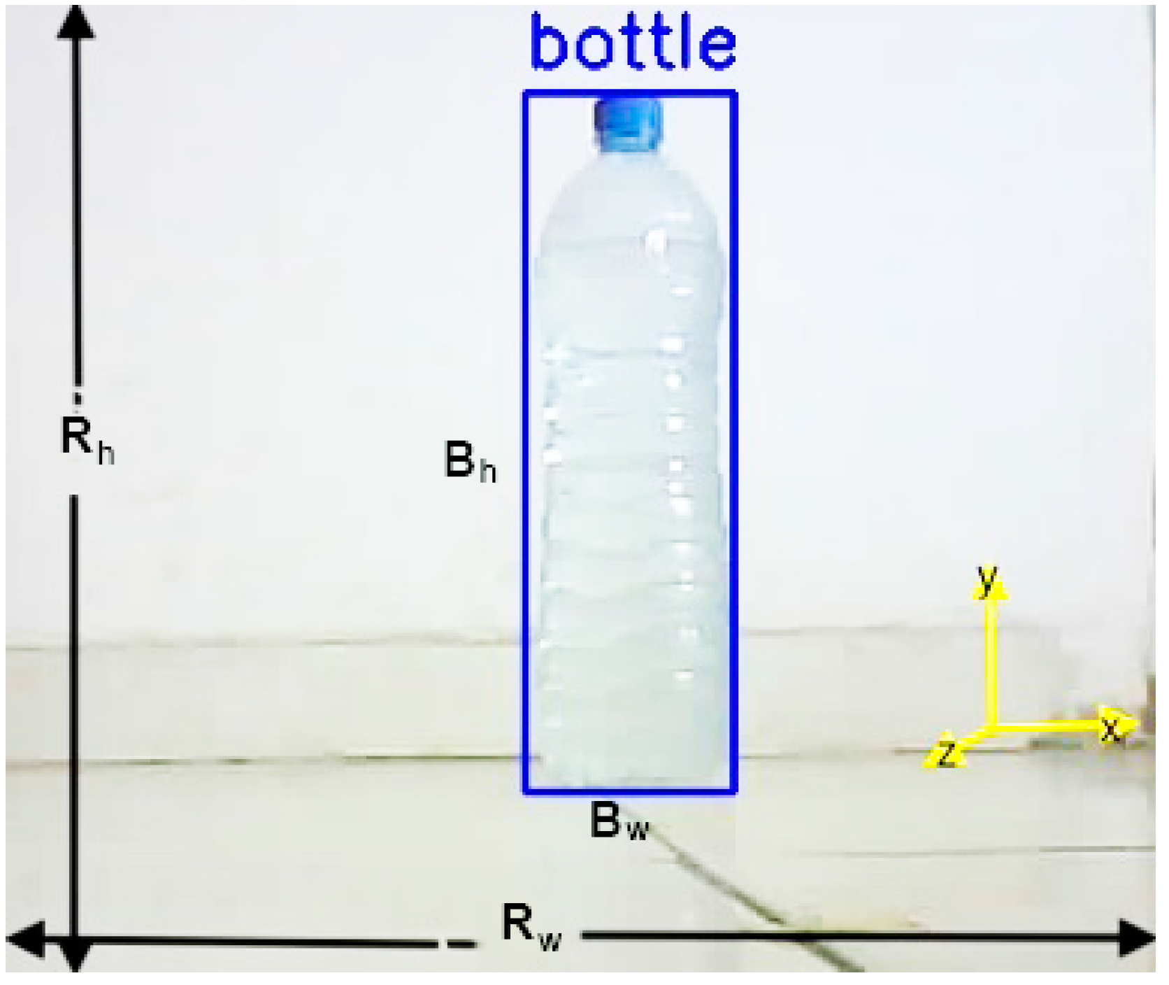
The object detection algorithm returns a bounding box which provides the width (Bw) and height (Bh) of the object in pixels. To calculate the actual size, the ratio of the bounding box height and image height (in pixels) is multiplied to the real image height.
where:
Ih = is the image height in pixels.
4.2. Spatial Coordinates
Under the assumption that radial distortions are negligible and that the optical axis of the camera is aligned with the ultrasonic sensor, the geometric center of the image corresponds directly to the center of the measuring device. In this configuration, the coordinates of the image’s center, denoted as (Icx, Icy), coincide with the point where the optical axis intersects the object plane, and a perpendicular line to the ultrasonic sensor.
Figure 6.
Deflection of an object showing change in vertical and horizontal axis from the center.
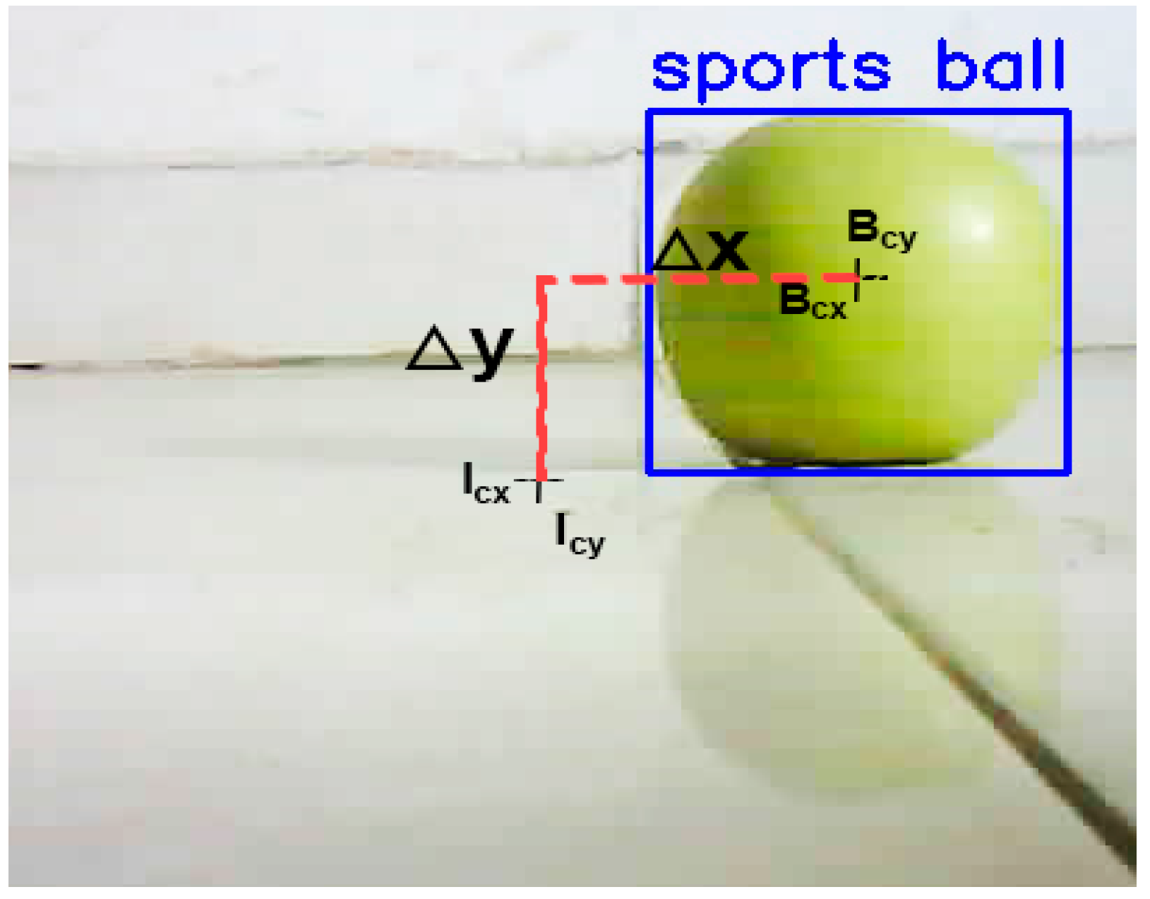
This implies that any deviation of the detected object’s center from the image’s center is directly related to the object’s displacement in the real-world environment, both horizontally and vertically. Specifically, let Bcx and Bcy represent the detected object’s center in the horizontal and vertical axes, respectively. Then, the deflection in the image plane can be modeled as:
where:
These deflections, Δx and Δy, are dimensionless rations which corresponds to the horizontal and vertical displacement of the object from the center of the measuring device.
To obtain the actual spatial displacement in horizontal and vertical axes these values are multiplied by the Real image heights and the real image width
The final axis for the spatial positioning is the depth (z-axis) which is gotten directly from the ultrasonic sensor. This sensor gets the distance by measuring time between the signal trigger and echo. According to the technical specifications of the ultrasonic sensor SRF05[27], the distance can be gotten by:
This computation is done within the ESP8266 microcontroller and since the computations in equations are all in millimeters, a conversion is required.
5. Experiment
5.1. Hardware Setup
The development of the spatial detection system underwent several iterations in both hardware and software design. The most significant design change was driven by the hardware limitation of the ESP32-CAM module. Although the ESP32-CAM is equipped with an onboard microcontroller, it lacks sufficient General-Purpose Input/Output (GPIO) pins to accommodate additional sensors. Furthermore, the majority of the module’s power resources are consumed by the camera, limiting its ability to efficiently support other peripherals.
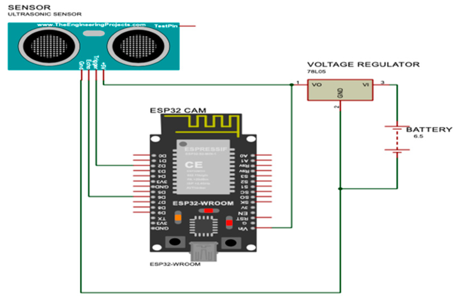
Figure 7.
Proposed design for the measurement system.
Upon realizing the ESP32-CAM’s limitations in managing additional sensors, a redesign was implemented. In this revised design, an ESP8266 microcontroller was introduced to handle ultrasonic sensor measurements. The ESP8266 is well suited to handle multiple sensors and has several GPIO pins for this purpose, further, it also has a WIFI module that enables communication over the network hence it was chosen as the alternative. The ESP8266 transmitted sensor data to a dedicated server, while the ESP32-CAM was responsible for video capture and sent image data to a separate server. This division of tasks allowed for more efficient resource management between the modules and ensured the system’s functionality.
Figure 8.
Modified circuit design for measurment system.
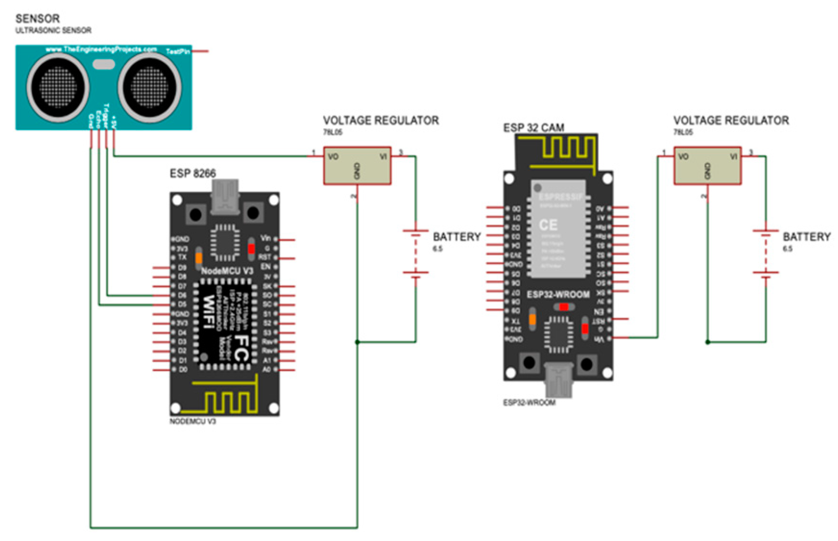
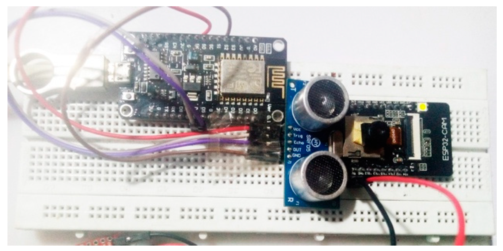
Figure 9.
Circuit wiring for the system showing the ESP32-CAM, ESP8266 and the Ultrasonic sensor.
The experiment was conducted indoors, utilizing four distinct test samples, each positioned at four varying distances from the measurement device. For each of the 16 experimental configurations, the number of data sets collected ranged from 27 to 47. To ensure optimal performance of the YOLO model and prevent failure due to insufficient lighting, adequate illumination was provided throughout the testing environment. The experiments were done against a plain background to minimize interference from extraneous objects.
The selected test samples varied in both color and size, including an apple, a banana, a water bottle, and a cup. The distance for measurement was set at 30 cm, 60 cm, 90 cm, and 120 cm, and data was collected for each of the samples individually. Data from each instance were systematically recorded and saved in CSV file for subsequent analysis.
5.2. Performance Metrics
The performance of this system was assessed by comparing the measured position and size of test samples with the predicted values. This analysis was applied to compute the measured and predicted sizes for all test samples. For each measurement, the processing time was defined as the time interval from the initial server was called to retrieve video and distance data to the completion of the spatial coordinate computation. This interval includes all system operations, from image acquisition to object detection and distance estimation. Figure 10 shows the time interval for each test case:
It is important to note that logging time—the time taken to record data or store results—was excluded from the processing interval to ensure a more accurate reflection of the real-time operational performance of the system.
The data collection process was carefully reviewed, and test cases with errors—such as instances where the ultrasonic sensor was misaligned and pointed at a different angle than the camera—were identified and excluded from further analysis.
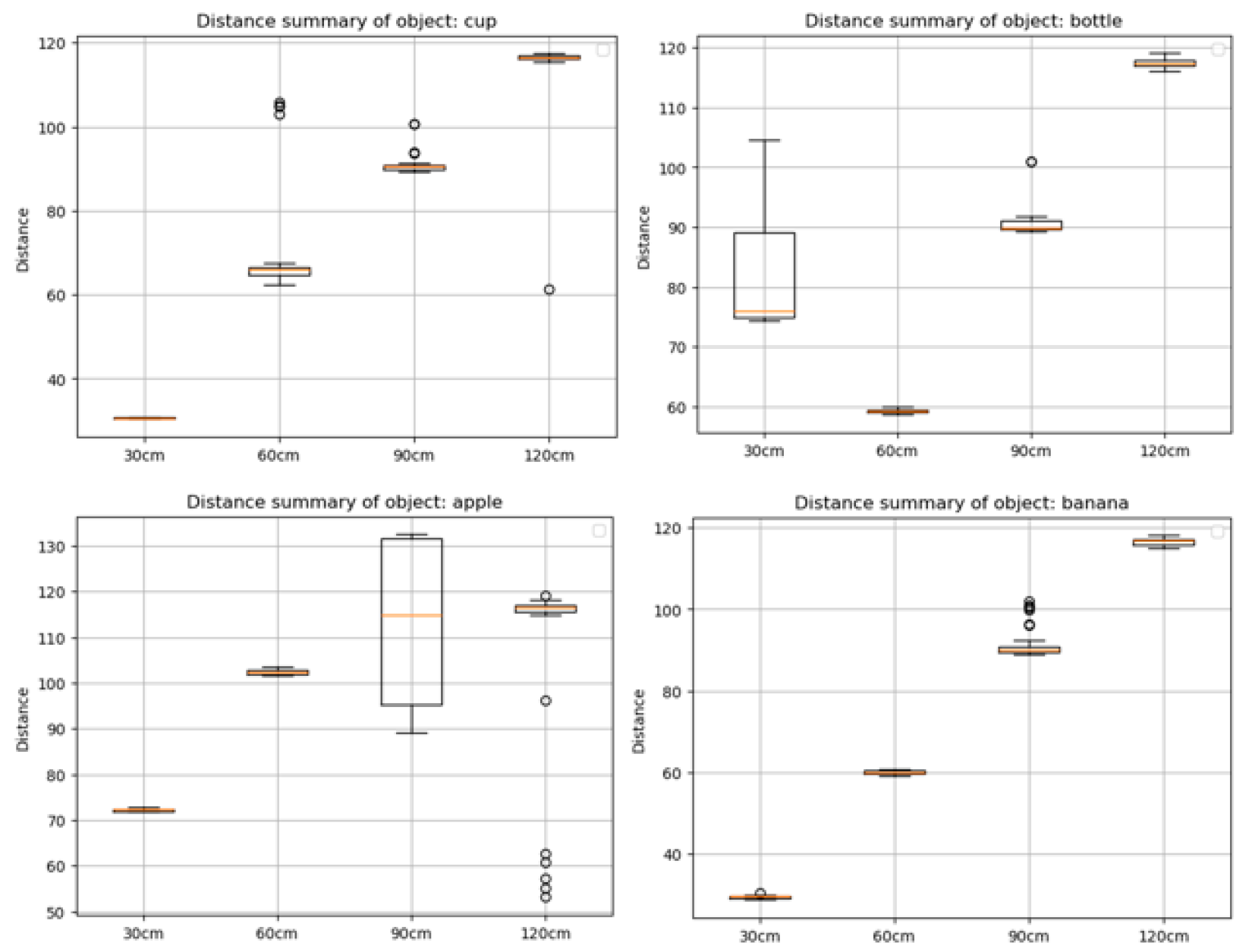
Distance from the ultrasonic sensor for each test sample is evaluated alongside the measured distance in Figure 11. This shows obvious anomaly in samples for apple in 30cm, 60cm and 90cm, and for bottle in 30cm. These values suggest misalignment of the ultrasonic sensor from the camera during those test cases. Hence the test samples were excluded from the performance evaluation of the system reducing the total number of test sets from 511 to 387 valid test sets.
To ensure proper evaluation of performance evaluation, error analysis was performed individually on the width, height, vertical(y-axis), horizontal(x-axis), and depth(z-axis) values.
Figure 12.
Error distribution for predictions in spatial positions and object size.
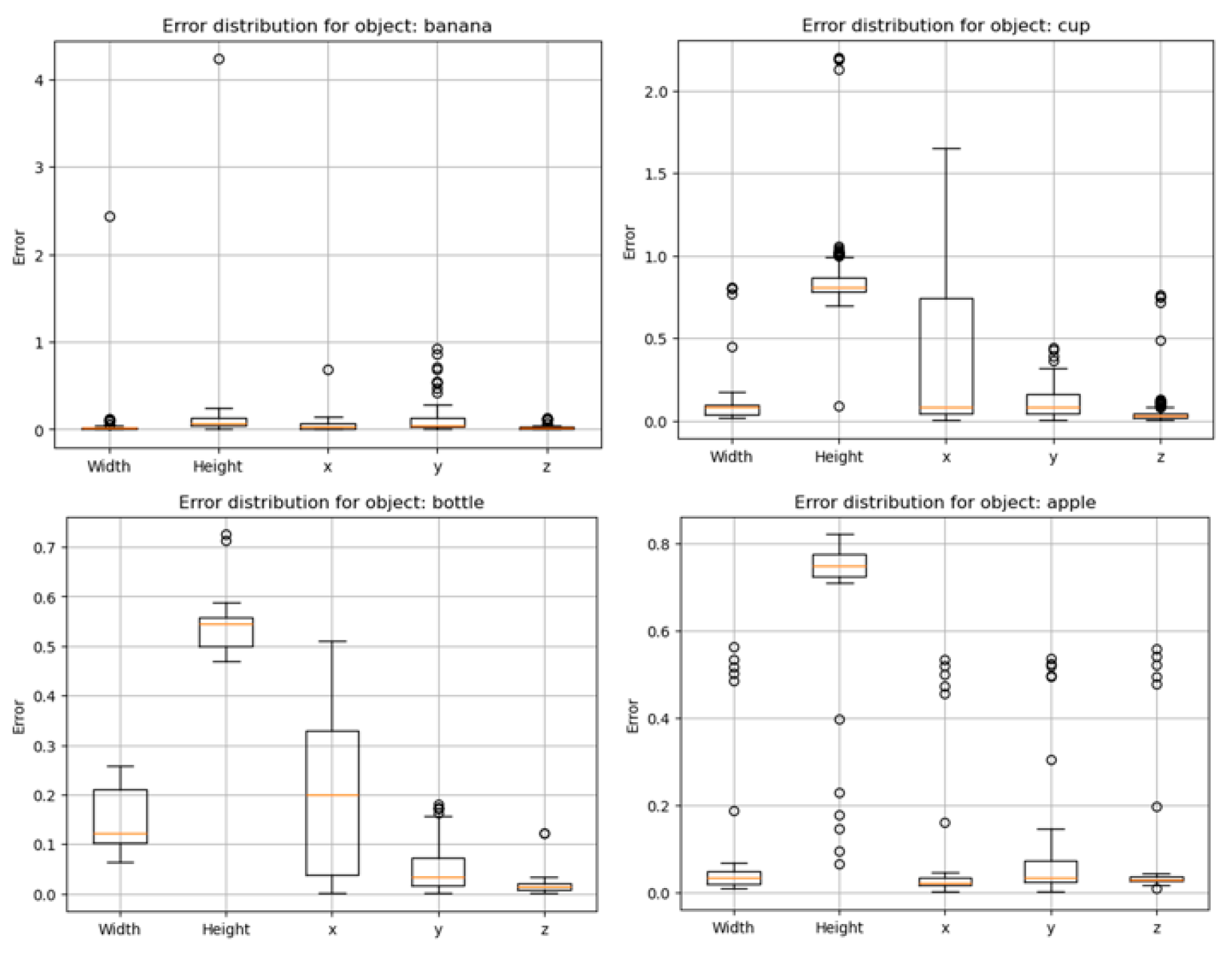
The table below presents the corresponding accuracy metrics for size and position, providing a detailed evaluation of the system’s precision.

Table 1.
Accuracy values on predictions.
| Accuracy | Value |
|---|---|
| Accuracy on width | 91.0672 |
| Accuracy on height | 49.5031 |
| Accuracy on x-axis | 79.8377 |
| Accuracy on y-axis | 90.5094 |
| Accuracy on z-axis | 95.9274 |
| Average Size accuracy | 70.2802 |
| Average Spatial accuracy | 88.7582 |
6. Discussion
79% of the experiment was collected under 600milliseconds with an average time of 715 milliseconds over all datasets. This is faster than the stereo vision in [22] which detects objects in 700milliseconds and maps the environment in 5 seconds. The spatial positioning showed a high accuracy value of 88.758% which is quite reliable for a system of its size and power consumption. While spatial positioning had a good accuracy value, the accuracy for size prediction was at 70% and object detection had an even lesser accuracy of 40%. The low performance in object detection points to the need for further training of the Yolov8 object detection model. Since this project made use of the default pretrained yolov8 model, it leaves room for further optimization. Also, training the model with test samples would greatly improve the performance of this model. Nevertheless, the boundary box performed well in determining the center of the object and this helped in increasing the efficiency of the spatial positioning.
6.1. Strengths of the Approach
The system demonstrates significant strengths, in spatial positioning particularly for objects in close-range. Its compact size and low power consumption make it suitable for deployment in unmanned vehicles with stringent space, weight, or power constraints. Furthermore, the system’s ability to transmit data over the network allows for real-time monitoring of the vehicle’s environment, with potential for integration with other cloud-based processing services. This cloud integration could further enhance the system’s functionality by enabling more complex decision-making processes based on the detected environmental data.
6.2. Limitations
One notable limitation of the system is the sensing range of the HY-SRF05 ultrasonic sensor, which is limited to 4 meters. This limits all obstacle detection and spatial positioning to a range of 4 meters.
Additionally, cameras encounter performance challenges in low-light conditions. This affects the YOLOv8 object detection algorithm which struggles to accurately identify objects due to inadequate lighting. To mitigate this, an automatic lighting system could be incorporated, controlled by light-dependent resistors (LDRs), which would turn on the lighting when environmental luminescence falls below a certain threshold. Since LDRs are energy-efficient, they would be ideal for use in unmanned vehicles operating under limited power conditions.
7. Applications and Future Work
7.1. Applications
This spatial detection system presents several potential applications across a range of fields. In unmanned ground vehicles and drones, the system can be effectively utilized for obstacle avoidance and real-time navigation of complex environments. Its ability to detect the position and size of objects also makes it suitable for autonomous robotics requiring the manipulation of robotic arms. Robotic arms could benefit from the system’s spatial detection capability to identify and track objects with accuracy.
Additionally, in the domain of search and rescue operations, this system holds significant potential. Its real-time detection and spatial positioning capabilities could aid in identifying potential casualties or obstacles, enabling autonomous robots to safely navigate through hazardous or unpredictable terrain. Furthermore, the system could be integrated into environmental mapping applications, providing real-time data for constructing accurate maps of unfamiliar or dangerous areas, a critical feature for autonomous exploration or disaster recovery missions.
7.2. Future Enhancements
While the current system demonstrates strong performance in short-range detection and spatial positioning, several enhancements could improve its capabilities for more demanding applications. One key improvement would be the replacement of the ultrasonic sensor with sensors suited for a wider range of measurement, such as LiDAR or RADAR. These sensors would extend the system’s range and offer more precise spatial data, enhancing its overall effectiveness in larger or more complex environments.
In addition to sensor upgrades, further refinement of the mathematical model could address issues such as radial distortions caused by the camera’s optics, leading to more accurate spatial positioning calculations. This improvement would significantly increase the reliability of the system, especially in situations requiring high precision.
Another promising direction for future work involves deploying machine learning models directly on the ESP32-CAM module. By training a lightweight model using TensorFlow Lite, it may be possible to run edge-case object detection algorithms, reducing the reliance on external computational resources and enabling real-time processing on the device itself. This would open up new possibilities for offline systems where real-time decision-making is crucial.
Further enhancements could also involve integrating GPS functionality to enable geographical mapping of obstacles, allowing the system to not only detect and avoid obstacles but also to chart their locations accurately. This integration could support interconnected systems where multiple autonomous vehicles communicate spatial data, improving collaborative navigation and environmental mapping efforts. The combination of spatial detection and geographic localization would make the system even more robust, particularly in applications such as swarm robotics, disaster recovery, or autonomous exploration.
8. Conclusions
This research has presented a sensor-fusion approach that integrates the ESP32-CAM module and ultrasonic sensor to achieve real-time object detection and spatial. By leveraging the object detection capacity of the YOLOv8, this system also identifies obstacles, giving a more reliable and accurate perception of the surrounding environment.
With the combination of an ultrasonic sensor and two ESP modules, this system uses low-cost hardware to achieve a spatial detection accuracy of 89%, which was validated through experiments with different object types at varying distances. With its real-time object detection capacity, this system presents an efficient and scalable option for various unmanned vehicle applications.
Despite the success of this approach, the limited sensing range of the ultrasonic sensor opens up an avenue for future enhancements. This could involve the use of LIDAR or RADAR to increase the sensing range. Additionally, deploying a lightweight machine learning model on the ESP32-CAM could enable edge computing, improving the system’s performance and scalability.
In conclusion, this study offers a cost-effective solution to enhance spatial positioning and object detection in unmanned vehicles. With further improvements, the device holds significant potential for broader applications in robotics, search and rescue, and environmental mapping.
References
- Sebastian Thrun, Wolfram Burgard, and Dieter Fox, Probailistic Robotics. 2000.
- M. Hussain, “YOLO-v1 to YOLO-v8, the Rise of YOLO and Its Complementary Nature toward Digital Manufacturing and Industrial Defect Detection,” Jul. 01, 2023, Multidisciplinary Digital Publishing Institute (MDPI). [CrossRef]
- J. M. Mern, K. D. Julian, R. E. Tompa, and M. J. Kochenderfer, “Visual Depth Mapping from Monocular Images using Recurrent Convolutional Neural Networks,” in AIAA Scitech 2019 Forum, Reston, Virginia: American Institute of Aeronautics and Astronautics, Jan. 2019. [CrossRef]
- M. Z. Butt, N. Nasir, and R. B. A. Rashid, “A review of perception sensors, techniques, and hardware architectures for autonomous low-altitude UAVs in non-cooperative local obstacle avoidance,” Rob Auton Syst, vol. 173, p. 104629, Mar. 2024. [CrossRef]
- K. Hatch, J. Mern, and M. Kochenderfer, “Obstacle Avoidance Using a Monocular Camera,” Dec. 2020. [CrossRef]
- R. Girshick, J. Donahue, T. Darrell, and J. Malik, “Rich feature hierarchies for accurate object detection and semantic segmentation Tech report (v5).” [Online]. Available: http://www.cs.berkeley.edu/˜rbg/rcnn.
- Vaswani et al., “Attention Is All You Need,” 2023.
- R. Girshick, J. Donahue, T. Darrell, and J. Malik, “Region-Based Convolutional Networks for Accurate Object Detection and Segmentation,” IEEE Trans Pattern Anal Mach Intell, vol. 38, no. 1, pp. 142–158, Jan. 2016. [CrossRef]
- R. Gavrilescu, C. Zet, C. Fosalau, M. Skoczylas, and D. Cotovanu, “Faster R-CNN:an Approach to Real-Time Object Detection,” in 2018 International Conference and Exposition on Electrical And Power Engineering (EPE), IEEE, Oct. 2018, pp. 0165–0168. [CrossRef]
- W. Liu et al., “SSD: Single Shot MultiBox Detector,” 2016, pp. 21–37. [CrossRef]
- J. Redmon, S. Divvala, R. Girshick, and A. Farhadi, “You Only Look Once: Unified, Real-Time Object Detection,” in 2016 IEEE Conference on Computer Vision and Pattern Recognition (CVPR), IEEE, Jun. 2016, pp. 779–788. [CrossRef]
- Y. Liu et al., “MMViT: Multiscale Multiview Vision Transformers,” Apr. 2023, [Online]. Available: http://arxiv.org/abs/2305.00104.
- N. Kitaev, Ł. Kaiser, and A. Levskaya, “Reformer: The Efficient Transformer,” Jan. 2020, [Online]. Available: http://arxiv.org/abs/2001.04451.
- L. Shen, B. Lang, and Z. Song, “Infrared Object Detection Method based on DBD-YOLOv8,” vol. 11. [CrossRef]
- F. N. Kılıçkaya, M. Taşyürek, and C. Öztürk, “Performance evaluation of YOLOv5 and YOLOv8 models in car detection,” Imaging and Radiation Research, vol. 6, no. 2, p. 5757, Jul. 2024. [CrossRef]
- J. Pan, “Spatial positioning method based on range-only measurement of multi-station radar,” Heliyon, vol. 10, no. 15, Aug. 2024. [CrossRef]
- M. Z. Butt, N. Nasir, and R. B. A. Rashid, “A review of perception sensors, techniques, and hardware architectures for autonomous low-altitude UAVs in non-cooperative local obstacle avoidance,” Rob Auton Syst, vol. 173, p. 104629, Mar. 2024. [CrossRef]
- K. Hatch, J. Mern, and M. Kochenderfer, “Obstacle Avoidance Using a Monocular Camera,” Dec. 2020. [CrossRef]
- J. M. Mern, K. D. Julian, R. E. Tompa, and M. J. Kochenderfer, “Visual Depth Mapping from Monocular Images using Recurrent Convolutional Neural Networks,” in AIAA Scitech 2019 Forum, Reston, Virginia: American Institute of Aeronautics and Astronautics, Jan. 2019. [CrossRef]
- S. Back, G. Cho, J. Oh, X.-T. Tran, and H. Oh, “Autonomous UAV Trail Navigation with Obstacle Avoidance Using Deep Neural Networks,” J Intell Robot Syst, vol. 100, no. 3–4, pp. 1195–1211, Dec. 2020. [CrossRef]
- L. Miccinesi et al., “Geo-Referenced Mapping through an Anti-Collision Radar Aboard an Unmanned Aerial System,” Drones, vol. 6, no. 3, p. 72, Mar. 2022. [CrossRef]
- K. V. Stefanik, J. C. Gassaway, K. Kochersberger, and A. L. Abbott, “UAV-Based Stereo Vision for Rapid Aerial Terrain Mapping,” GIsci Remote Sens, vol. 48, no. 1, pp. 24–49, Jan. 2011. [CrossRef]
- N. Gageik, P. Benz, and S. Montenegro, “Obstacle Detection and Collision Avoidance for a UAV With Complementary Low-Cost Sensors,” IEEE Access, vol. 3, pp. 599–609, 2015. [CrossRef]
- X. Huang et al., “The Improved A* Obstacle Avoidance Algorithm for the Plant Protection UAV with Millimeter Wave Radar and Monocular Camera Data Fusion,” Remote Sens (Basel), vol. 13, no. 17, p. 3364, Aug. 2021. [CrossRef]
- S. Gadde, M. S. Gadde, N. Mohanty, and S. Sundaram, “Fast Obstacle Avoidance Motion in Small Quadcopter operation in a Cluttered Environment,” in 2021 IEEE International Conference on Electronics, Computing and Communication Technologies (CONECCT), IEEE, Jul. 2021, pp. 1–6. [CrossRef]
- “Advanced Information Preliminary Datasheet OV2640,” 2006.
- Robot Electronics, “SRF05 - Ultra-Sonic Ranger Technical Specification.” Accessed: Oct. 16, 2024. [Online]. Available: https://www.robot-electronics.co.uk/htm/srf05tech.htm.
- Richard Hartley and Andrew Zisserman, Multiple View Geometry in Computer Vision, Second. Cambridge University Press.
- Wayne Fulton, “Calculate Distance or Size of an Object in a photo image.” Accessed: Oct. 11, 2024. [Online]. Available: https://www.scantips.com/lights/subjectdistance.html.
Figure 4.
Thin lens model diagram [28].
Figure 4.
Thin lens model diagram [28].
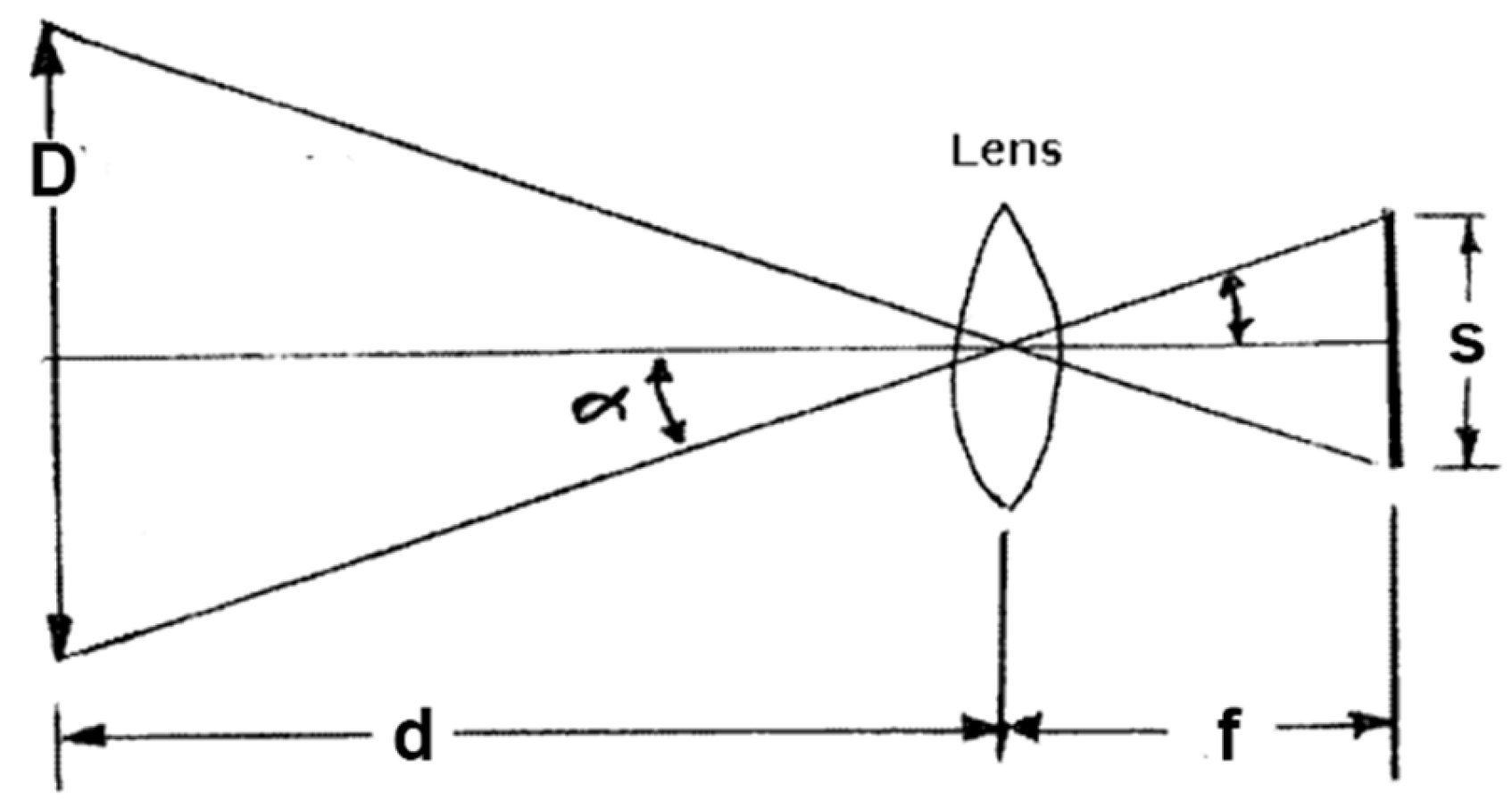
Figure 10.
Prediction interval: Box plot showing the prediction interval for each test case.
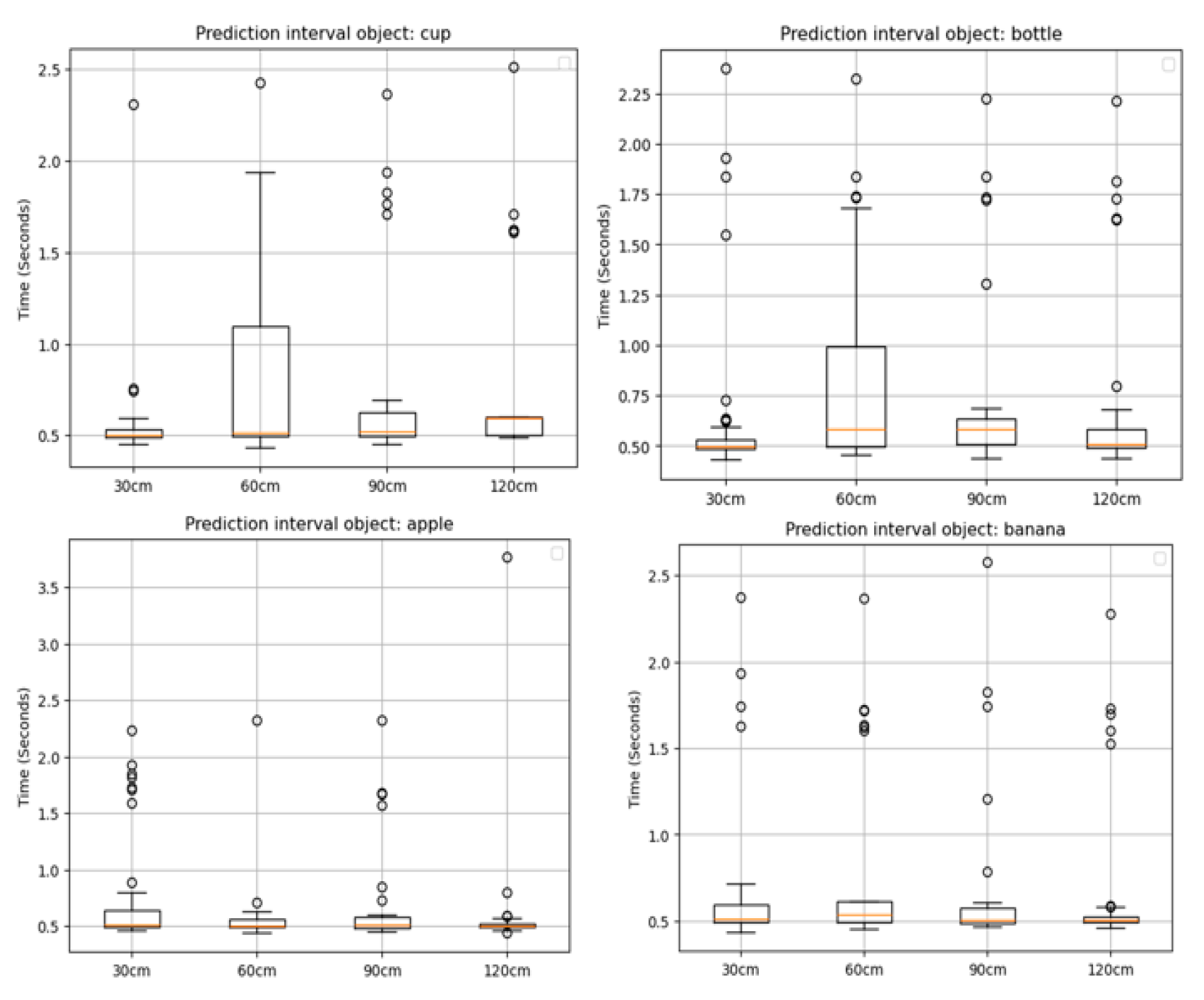
Figure 11.
Recorded distance from measuring device: This graph helps to detect anomaly in the operation of the ultrasonic sensor.
Figure 11.
Recorded distance from measuring device: This graph helps to detect anomaly in the operation of the ultrasonic sensor.
Disclaimer/Publisher’s Note: The statements, opinions and data contained in all publications are solely those of the individual author(s) and contributor(s) and not of MDPI and/or the editor(s). MDPI and/or the editor(s) disclaim responsibility for any injury to people or property resulting from any ideas, methods, instructions or products referred to in the content. |
© 2024 by the authors. Licensee MDPI, Basel, Switzerland. This article is an open access article distributed under the terms and conditions of the Creative Commons Attribution (CC BY) license (http://creativecommons.org/licenses/by/4.0/).
Copyright: This open access article is published under a Creative Commons CC BY 4.0 license, which permit the free download, distribution, and reuse, provided that the author and preprint are cited in any reuse.


