
Submitted:
05 November 2024
Posted:
06 November 2024
You are already at the latest version
Abstract
This study addresses the challenge of dispersing disinfectant liquids for sanitizing people, indoor spaces, vehicles, and outdoor areas. Fine aerosol sprays with a large surface area of particles are considered the most promising solution for such tasks. The study identifies shortcomings in current spraying methods and highlights the potential of ultrasonic liquid atomization for improving disinfection processes. Innovative specialized ultrasonic atomizers are introduced, capable of producing aerosols with the required droplet size and efficiency from disinfectant liquids of varying viscosities, including those containing silver nanoparticles.
Keywords:
virus
; disinfection
; ultrasound
; ultrasonic atomization
; cleaning
1. Introduction
Viruses pose a significant biological threat to humanity. Their high natural (and possibly engineered) capacity to mutate makes the timely development of vaccines difficult, if not impossible, in some caseshe emergence of COVID-19, the virus has claimed many lives, and despite the end of the pandemic, it continues to circulate within the human population, causing new fatalities [1]. Additionally, new dangerous viruses, such as the monkeypox virus, are emerging [2]. One co of infection is contact with surfaces contaminated with droplets from infected individuals when they cough, talk, or sneeze. During the COVID-19 pandemic, stringent hygiene standards were enforced and closely monitored [3].
On May 15, 202ld Health Organization (WHO) issued guidelines on the use of disinfectant spraying systems for surface cleaning to eliminate pathogens from contaminated areas. WHO emphasized that direct contact with recommended disinfectants can sterilize surfaces and neutralize certain disinfectants' bactericidal properties [4]. In this context, preventtion with various disinfectant solutions remains an effective means of controlling virus transmission. Disinfection can be applied to individuals, their clothing, indoor spaces (including public areas), and open spaces such as city streets. For instance, in one study [5], a design for walk-through gates wd, incorporating systems for monitoring infected individuals and disinfecting them.
Effective application of disinfectants requires precise control of time and concentration for optimal disinfection of surfaces and air. Traditional methods of disinfection include liquid solutions like sodium hypochlorite (bleach/chlorine) and alcohol in concentrations of 70–90%, as well as ultraviolet (UV) light, which can destroy viral DNA. However, these methods have faced criticism from environmental protection agencies. Unregulated use of highly concentrated disinfectants can lead to environmental issues [6], pose health risks to people [7], and damage surfaces [8]. Moreover, it is not possible to quickly disinfect large rooms and open spaces without the use of special devices. Thus, the development of devices that enable various spraying methods tailored to specific objectives is a pressing need, alongside other innovative disinfection techniques [9].
The most commonly used disinfection spraying methods today are hydraulic and pneumatic. While these methods are technically simple to implement, they have several significant drawbacks.
The main disadvantage of hydraulic spraying is the formation of large droplets (about 1 mm in size), which settle quickly due to gravity and offer low surface area-to-volume ratios. Most of the disinfectant is wasted in forming these large droplets, which fail to evenly coat the surface. As a result, excessive amounts of disinfectant are used, "drenching" people and surfaces. Conversely, pneumatic methods generate droplets that are too small (2–4 µm) to reach surfaces before evaporating into the air. Additionally, pneumatic atomization has low process efficiency. Both methods produce droplets with a wide size distribution, creating technological challenges [10]. These limitations stem from fundamental physical effects that determine how the liquid form into droplets [11]. Furthermore, traditional spraying methods can cause droplets to evaporate or shatter upon impact, rebound and inefficient surface coverage. This not only reduces effectiveness but can also be harmful, damaging clothing and irritating mucous membranes in the eyes, nose, and mouth [6].
The inability to consistently generate droplets of a specific size with adequate efficiency has prevented the development of a standardized methodology for disinfecting different surfaces, objects, and individuals. Thus, the need for developing and implementing new, selective, and highly effective spraying methods is critical. These methods must be capable of producing aerosol particles of optimal size and in sufficient quantity for safe and effective application of disinfectants to various objects and people [12].
One such method is ultrasonic liquid atomization. This technique involves the use of ultrasonic vibrations on a liquid film located on the oscillating surface of an ultrasonic transducer. Capillary waves form on the liquid surface, and when the waves reach a critical amplitude, they break into droplets [13].
This mechanism allows ultrasonic atomization to produce a nearly monodisperse droplet size distribution with the lowest energy costs compared to other methods. It also facilitates the atomization of two-phase mixtures (liquids containing dispersed particles) while ensuring the uniform distribution of nanoparticles (e.g., silver) within the droplets, preventing spontaneous agglomeration.
Ultrasonic atomization technology allows control over the droplet size by adjusting the frequency of the ultrasonic vibrations. As frequency increases, the average droplet diameter decreases exponentially, from 90 µm at 25 kHz to 10 µm at 200 kHz (for water) [13]. Furthermore, the deviation in droplet size from the average is minimal compared to other spraying methods.
Therefore, the ability to proow droplet size distribution prevents the formation of hazardous small-droplet clouds (as seen with pneumatic spraying) and avoids the excessive application of disinfectants from large droplets (as seen with hydraulic spraying). Additionally, the ability to adjust droplet size by altering the frequency of ultrasonic vibrations enables the design of devices tailored to specific disinfection needs. This allows for the creation of ultrasonic atomizers capable of generating droplets in the optimal size and quantity for various practical applications. However, the current limitation of this method is its low aerosol cloud production rate (approximately 1–2 mL/s), which must be addressed through innovative combined techniques.
It is important to note that disinfectant liquids vary in their physicochemical properties. They typically have lower surface tension than water due to the presence of surfactants and may also have higher viscosity. These solutions can be two-phase systems containing special dispersed additives, such as silver nanoparticles. These characteristics impose additional requirements on ultrasonic atomization methods and devices.
The objective of this study is to describe innovative methods and devices for ultrasonic and combined atomization of disinfectant liquids with varying physicochemical properties.
2. Development of Ultrasonic and Combined Spraying Devices for Disinfectant Liquids
Analysis of existing data on the disinfection of various objects allows for the categorization of disinfection approaches based on the characteristic scales, distance from the sprayer to the object, and the required droplet size [14]:
- For disinfecting people in factories, offices, hospitals, public places (including land, underground, and air transportation), and restaurants, tective droplet size is 10–35 µm.
- For disinfecting indoor spaces and vehicles, droplet sizes between 25–70 µm are ideal.
- For disinfecting open spaces (e.g., roads, buildings, pavilions, recreational areas), droplet sizes of 150–300 µm are required.
Thus, the spraying capacity must vary significantly to ensure the correct number of droplets for even surface coverage in a single layer, where the layer thickness does not exceed the droplet size.
The versatility of ultrasonic atomization, combined with the wide range of disinfection tasks, requires the development and use of specialized equipment. Recent research and development efforts [15] indicate that the authors’ ultrasonic atomizers can address these challenges effectively.
2.1. Ultrasonic Liquid Layer Sprayers
The ultrasonic atomizer consists of an ultrasonic oscillating system (ultrasonic nozzle) and an electronic generator for its power supply. The design of the oscillating system is shown in Figure 1.
The shape of the spray surface determines the geometric characteristics of the spray torch, and the area of the spray surface determines the spray performance. The shape and size of the spray surface may vary depending on the specific purpose of the sprayer.
Since the liquid flowing from the opening onto the spray surface spreads out in the form of a circle with a radius of R0. The value of this radius is determined by the viscosity and surface tension of the liquid and can be determined by the dependencies presented in the work [16]. If the radius of the spray surface exceeds the value of R0, then it becomes necessary to make additional channels on the spray surface to ensure increased spray performance.
The location and number of additional channels for delivering liquids to the spray surface are determined from the condition of ensuring its uniform coverage with a layer of sprayed liquid. Figure 2 shows the optimal location of additional channels for supplying the sprayed liquid.
To cover the remaining area of the spray surface with liquid, it is necessary to make these holes at a distance of 2R0 from each other along the cone generatrix (Figure 2b). In this case, the most rational is to place additional holes (in addition to the central hole made at the top of the cone) on the circles (Figure 2c). Figure 2d shows that the radius of these circles will increase by with each new circle located further from the center of the cone. The number of circles is calculated so that they are located at a distance of 2R0 from each other and at a distance of R0 from the outer edge. With a known radius of the spray surface R, the length of the cone generatrix will be equal to . Then the number of circles that can be placed along such a cone generatrix will be equal to
or, moving to a common denominator:
If the obtained value is not an integer, then it is rounded to the nearest integer value and the R0 value is specified, , hence:
The radius of each circle will be equal to:
where i = 0…N is the circle number.
The centers of the holes of the channels for supplying liquid on each of the circles are also uniformly located at a distance of 2 R0 from each other along the length of the circle. The number of channels on each circle is:
After we have increased the productivity of ultrasonic spraying by creating additional channels, the task of transporting the formed aerosol to the objects of disinfection arises. Since the liquid droplets formed by the ultrasonic sprayer have a low speed of separation from the liquid film, then to form a spray torch with a direction different from the vertically directed downwards, it is necessary to use additional air flows, as shown in Figure 3.
In ultrasonic spraying, air flows are intended only for transporting already formed droplets.
Below are several different types of sprayers, differing in operating frequency (size of formed droplets) and productivity, which can be used as a basis for creating specialized devices for disinfecting various objects. The currently implemented range of operating frequencies of sprayers is from 18 to 160 kHz [17,18,19,20,21]. Increasing the frequency in this range allows reducing the average size of formed particles from 65 to 18 μm. However, with an increase in the spray frequency from 22 to 160 kHz, productivity decreases by 100 times.
All developed sprayers should be conditionally divided into several groups, shown in Figure 4.
The technical characteristics of the sprayers are presented in Table 1.
For the practical implementation of the disinfection process, devices of various designs can be used based on the developed ultrasonic sprayers, both for manual spraying and for use in mobile devices.
2.2. High-Capacity Wearable Atomizer Designs for Generating a Variety of Particle Sizes
Figure 5 shows a device for forming an aerosol with an average particle size of no more than 50 μm and a capacity of up to 20 ml/s for treating people's clothing, vehicles and small rooms. To provide an increased spray area, a flexural-oscillating disk (oscillations are carried out on the second mode) with a diameter of 40 mm is used. The resonant frequency of the sprayer is 40 kHz. Liquid is supplied to the spray surface through 12 through holes made in the areas of zero oscillations of the disk.
Figure 6 shows a high-performance sprayer for forming an aerosol with an average particle size of 65 microns and a capacity of more than 60 ml/s, designed for treating public transport, the metro and premises. To ensure such high performance (more than 60 ml/s), the area of the spray surface was significantly increased. By analogy with the previous device, it is made in the form of a bending-oscillating disk. The diameter of the disk is increased to 250 mm, it oscillates in mode 3.
The sprayed liquid is in a backpack container, which is located behind the operator. A liquid supply system (pump and valve) is installed on the liquid container. An electronic generator for powering the ultrasonic sprayer is also installed on the backpack container. The electronic generator is powered by high-current lithium-ion batteries.
Thus, a number of ultrasonic sprayer models have been developed that have good user characteristics - high dispersion, narrow particle size distribution, satisfactory performance for a number of tasks. Their operating principle is based on the excitation of capillary waves in a liquid film using ultrasonic vibrations.
In the presented devices, an increase in spray performance is achieved by significantly increasing the area of the spray surface. However, it is not possible to infinitely increase the area of the spray surface. This requires the development of new ultrasonic liquid spraying methods based on a combination of ultrasonic action and other factors.
Below, two new ultrasonic liquid spraying methods based on other principles are described. First of all, they use the phenomenon of ultrasonic cavitation.
2.3. Innovative Acoustic-Dynamic Methods and Devices for Spraying Disinfectant Liquids
2.2.1. Multi-Stage Spraying
When spraying a liquid layer with ultrasound, droplet formation occurs in one stage, when droplets break away from the liquid film. In this case, the higher the ultrasound frequency, the higher the dispersion of aerosols, which is preferable in the problem under consideration. However, the generation of high-frequency oscillations (more than 80 kHz) with an amplitude sufficient for spraying limits the area of the radiating surface. Such oscillations are damped in the sprayed liquid and absorbed by the material of the ultrasonic emitter, which reduces the efficiency of spraying. To overcome this limitation, a method of multi-stage ultrasonic spraying with the supply of acoustic energy to the liquid through gas is proposed [22]. The concept of implementing the proposed method of ultrasonic spraying is shown in Figure 7.
The initial aerosol is formed by any method of atomization with sufficient productivity. In the case of technologically simple methods (e.g. hydraulic, low-frequency ultrasound, etc.), the initial aerosol will have low dispersion (droplet size of about 1-10 mm). The primary flow of large droplets moves either due to gravity or is carried away by the transport gas flow towards the next stages of atomization.
At the next stages, the droplets enter the ultrasonic field (standing ultrasonic wave) in the gas. The droplets are broken down into smaller fragments at the antinodes of the standing wave due to deformation and loss of stability (Kelvin-Helmholtz instability). Under the action of the energy of the ultrasonic field and upon interaction with air, the droplets are atomized in accordance with one of the mechanisms classified by morphological features [23,24,25]. As a result of such interaction of the droplets with the antinodes of the ultrasonic field, a gradual destruction of the droplets occurs up to a certain limit (minimum size).
The developed method of ultrasonic atomization is implemented by means of a bending-diametrically oscillating tubular ultrasonic emitter. It is a hollow cylinder with a stepwise changing external and constant internal diameter. The internal diameter of the tubular emitter is selected from the condition of ensuring the resonance of ultrasonic vibrations in the internal air cavity of the tubular emitter (formation of a standing acoustic wave), at the operating frequency of the emitter. The shape of the external surface of the emitter is determined from the condition of ensuring a uniform distribution of the amplitude of ultrasonic vibrations along the length of the emitter. Excitation of oscillations of the tubular emitter with an intensity sufficient to destroy droplets can be carried out using a multi-element transducer with radially located Langevin transducers [26]. A drawing of the tubular emitter and the distribution of the oscillation amplitude are shown in Figure 8.
The results of the calculations of the distribution of sound pressure created by the emitter, as well as a photograph of the manufactured emitter are shown in Figure 9. The calculation of the distribution of the sound pressure level inside the tubular emitter was carried out in the ANSYS program. During the calculations, an iterative change in the emitter dimensions was made to ensure the formation of a standing wave in the internal cavity of the emitter at the emitter oscillation frequency.
As a result of modeling, the maximum sound pressure level on the emitter axis was determined to be 190 dB, with the standing wave consisting of three maxima successively located along the emitter. This ensures five stages of liquid droplet spraying. The developed emitter operates at a frequency of 22.4 kHz. The acoustic power emitted into the air is 35 W, the amplitude (span) of surface oscillations max-min 51-40 μm; electric power is 48 W. The experimental sample has the following dimensions: D2 = 92 mm, D1 = 52 mm, L = 96 mm.
2.2.2. Cavitation Combined Method
To overcome the limitations of ultrasonic liquid spraying methods in terms of productivity, we propose to combine the advantages of the hydraulic spraying method (with high productivity) with the capabilities of ultrasonic cavitation (to ensure high droplet dispersion). The main idea is to create a cavitation region in a liquid under excess pressure. To do this, a cavitation region must be created directly at the point where the liquid flows out of the hydraulic nozzle. The ultrasonic emitter placed here affects the volume of liquid above the end surface of its working end with ultrasonic vibrations. An important condition is a sufficiently high vibration amplitude, exceeding the threshold for creating cavitation in the liquid. Schematically, the cavitation combined spraying method is shown in Figure 10.
Hydraulic pressure determines the flow rate (and spray performance). Cavitated liquid flows out of the hole forming droplets containing cavitation bubbles. The collapse of the bubbles generates a pressure pulse, which causes the droplet to break into smaller fragments. Ultrasound characteristics (amplitude and frequency) determine the parameters of the cavitation region and, ultimately, the dispersion of the droplets.
The proposed cavitation combined spray method is implemented using a two-half-wave ultrasonic emitter. A sketch and a photo of the emitter with a resonant frequency of 22.1 kHz are shown in Figure 11.
After manufacturing and assembling the emitters and transducers, the oscillation amplitude of the emitting end was measured. The measurement results showed that the maximum oscillation amplitude of the end surface of the developed piezoelectric transducer was 30 μm. The obtained oscillation amplitude values are sufficient to create cavitation in the liquid.
3. Discussion of the Results of the Development of Methods and Devices for Spraying Disinfectant Liquids
3.1. Droplet Size in Ultrasonic Atomization of a Thin Liquid Layer
Droplet size measurements during ultrasonic spraying of a thin film at different frequencies showed that ultrasonic spraying allows for the formation of a narrow-spectrum and smaller-size droplet distribution (Figure 12). For comparison, the figure shows the particle sizes of an aerosol formed by a hydraulic nozzle. However, the productivity of ultrasonic spraying is about 10...20 ml/s, while with hydraulic spraying it depends on the liquid pressure and can significantly exceed 100 ml/s.
This section may be divided by subheadings. It should provide a concise and precise description of the experimental results, their interpretation, as well as the experimental conclusions that can be drawn.
3.2. Droplet Size in Multi-Stage Ultrasonic Atomization
In multi-stage spraying, liquid is supplied to the input using any technically simple and inexpensive technology, such as a hydraulic nozzle or ultrasonic spraying of a liquid layer. Spraying performance will depend on the performance of the initial liquid feed. Since three antinodes of ultrasonic vibrations are formed along the axis of the developed emitter, it will provide three stages of droplet fragmentation to a certain maximum size.
To confirm the operability of the proposed spraying method, the dispersed composition of droplets formed during spraying of water (settled, tap water, temperature 23 °C) was preliminarily analyzed. Sound pressure level 160-182 dB. Water feed performance 5-30 ml/sec. The initial size of droplets entering the tubular emitter was 1500-2000 μm. Histograms of droplet distribution at the outlet of the tubular emitter are shown in Figure 13.
A significant decrease in droplet size compared to the initial value was obtained in the experiment over the entire range of sound pressure. The average droplet size of the resulting aerosol (the Sauter diameter) depends linearly on the sound pressure level (Figure 14a). With an increase in the liquid feed rate to the device input, the droplet size increases (Figure 14b) – initially slightly, then more strongly.
Changing the sound pressure level in the range of 160–182 dB allows you to adjust the average diameter of the formed droplets within 37–170 µm. Thus, multi-stage ultrasonic atomization allows you to significantly reduce the size of the droplets supplied to the input and control the dispersion of the final aerosol over a wide range. At the same time, the spraying performance is limited only by the performance of the device generating the incoming aerosol.
3.3. Droplet Size in Combined Cavitation Spraying
When implementing this spraying method, it was found that there is an optimal mode corresponding to a pair of values: liquid hydraulic pressure – ultrasonic vibration amplitude. This pair corresponds to the optimal mode, in which developed cavitation is established in the pre-nozzle volume. In this case, the aerosol dispersion is the highest. Figure 15 shows the dependences of the critical ultrasound amplitude and the Sauter diameter of the aerosol in the optimal mode on the hydraulic pressure.
With increasing liquid pressure, it is necessary to increase the ultrasound amplitude to achieve the optimal mode, in which the droplet size will be minimal. At the same time, with increasing pressure in the optimal mode, the droplet size decreases. Also, with increasing pressure, the liquid flow rate increases, as is typical for hydraulic nozzles. In our case, this increase was from 4-5 ml/s for 2 atm to 14-15 ml/s for 12 atm. Typical histograms of aerosol particle size distribution for 6 atm and 11 atm are shown in Figure 16.
Thus, the implementation of the optimal cavitation mode in the combined acoustic-dynamic spraying method allows obtaining a highly dispersed aerosol with a sufficiently high productivity.
4. Conclusions
The presented results of extensive years of research and development offer a highly effective solution to the challenge of dispersing disinfectant liquids for sanitizing people, indoor spaces, vehicles, and outdoor areas through the use of ultrasonic liquid atomization.
Currently implemented spraying systems based on hydraulic, pneumatic, and similar methods have notable drawbacks when generating disinfectant aerosols. The droplet sizes are either too large or too small, with a wide size distribution. Traditional methods also often fail to handle liquids with high viscosity, surface tension, or two-phase mixtures (liquids containing nanoparticles). These limitations are effectively overcome by ultrasonic atomization techniques, making them a promising approach for disinfection.
The developed specialized ultrasonic devices are capable of producing aerosols with the required droplet size and output, even with disinfectant liquids of varying viscosities, including those containing silver nanoparticles. Innovative acoustodynamic spraying methods (such as combined cavitation and multistage techniques) allow for the creation of disinfectant aerosols with controlled droplet size and high efficiency.
The use of advantages of ultrasonic atomization, along with the development and practical application of devices based on this principle, will ensure reliable protection for people, transportation, and spaces.
Author Contributions
Conceptualization, A.S., V.K. and O.K.; methodology, A.S. and V.K.; software, S.T. and V.N.; validation, A.S. and O.K.; formal analysis, O.K.; investigation, D.G.; resources, A.S.; data curation, V.N and D.G.; writing—original draft preparation, A.S. and O.K.; writing—review and editing, A.S., S.T. and O.K.; visualization, V.N. and S.T.; supervision, V.K.; project administration, A.S.; funding acquisition, A.S. All authors have read and agreed to the published version of the manuscript.
Funding
This study was carried out with a grant from the Russian Science Foundation № 23-19-00875, https://rscf.ru/project/23-19-00875/ (accessed on 29 October 2024).
Data Availability Statement
Data is contained within the article or supplementary material.
Conflicts of Interest
The authors declare no conflicts of interest.
References
- Jiang, X.; Fan, Z.; Li, S.; Yin, H. A review on zoonotic pathogens associated with non-human primates: Understanding the potential threats to humans. Microorganisms 2023, 11(2), 246. [Google Scholar] [CrossRef]
- Mitjà, O.; Ogoina, D.; Titanji, B.K.; Galvan, C.; Muyembe, J.J.; Marks, M.; Orkin, C.M. Monkeypox. The Lancet 2023, 401(10370), 60–74. [Google Scholar] [CrossRef]
- Bujňák, M.; Pirník, R.; Kuchár, P.; Rástočný, K. Assessing the Risk of Spreading COVID-19 in the Room Utilizing Low-Cost Monitoring System. Applied System Innovation 2023, 6(2), 40. [Google Scholar] [CrossRef]
- World Health Organization. Cleaning and Disinfection of Environmental Surfaces in the Context of COVID-19: Interim Guidance, 15 May 2020; World Health Organization: Geneva, Switzerland, 2020. [Google Scholar]
- Hussain, S.; Cheema, M.J.M.; Motahhir, S.; Iqbal, M.M.; Arshad, A.; Waqas, M.S.; Malik, S. Proposed design of walk-through gate (WTG): mitigating the effect of COVID-19. Applied System Innovation 2020, 3(3), 41. [Google Scholar] [CrossRef]
- Subpiramaniyam, S. Outdoor disinfectant sprays for the prevention of COVID-19: Are they safe for the environment? Science of the Total Environment 2021, 759, 144289. [Google Scholar] [CrossRef] [PubMed]
- Clausen, P.A.; Frederiksen, M.; Sejbæk, C.S.; Sørli, J.B.; Hougaard, K.S.; Frydendall, K.B.; Wolkoff, P. Chemicals inhaled from spray cleaning and disinfection products and their respiratory effects. A comprehensive review. International journal of hygiene and environmental health 2020, 229, 113592. [Google Scholar] [CrossRef] [PubMed]
- Andersen, B.M.; Rasch, M.; Hochlin, K. Jensen, F.H.; Wismar, P.; Fredriksen, J.E. Decontamination of rooms, medical equipment and ambulances using an aerosol of hydrogen peroxide disinfectant. Journal of Hospital Infection 2006, 62(2), 149. [CrossRef]
- Kchaou, M.; Abuhasel, K.; Khadr, M.; Hosni, F.; Alquraish, M. Surface disinfection to protect against microorganisms: Overview of traditional methods and issues of emergent nanotechnologies. Applied Sciences 2020, 10(17), 6040. [Google Scholar] [CrossRef]
- Park, S.; Park, K. Principles and droplet size distributions of various spraying methods: A review. Journal of Mechanical Science and Technology 2022, 36(8), 4033–4041. [Google Scholar] [CrossRef]
- Nasr, G.G.; Yule, A.J.; Bendig, L. Industrial sprays and atomization: design, analysis and applications; Springer Science & Business Media, 2013.
- Khmelev, V.N.; Shalunov, A.V.; Khmelev, S.S.; Tsyganok, S.N. Ultrasound. Devices and technologies: monograph Biysk: Alt Publishing House. state tech. un-ta. 2015.
- Zhang, Y.; Yuan, S.; Wang, L. Investigation of capillary wave, cavitation and droplet diameter distribution during ultrasonic atomization. Experimental Thermal and Fluid Science 2021, 120, 110219. [Google Scholar] [CrossRef]
- Gebel, J.; Exner, M.; French, G.; Chartier, Y.; Christiansen, B.; Gemein, S.; Sonntag, H. G. The role of surface disinfection in infection prevention. GMS hygiene and infection control, (2013). 8(1). [CrossRef]
- Center of Ultrasound Technologies. Available online: https://u-sonic.ru, (accessed on 25.10.2024).
- Khmelev, V.N.; Shalunov, A.V.; Golykh, R.N.; Nesterov, V.A.; Dorovskikh, R.S.; Shalunova, A.V. Determination of the modes and the conditions of ultrasonic spraying providing specified productivity and dispersed characteristics of the aerosol. Journal of Applied Fluid Mechanics 2017, 10(5), 1409–1419. [Google Scholar] [CrossRef]
- Khmelev, V.N.; Shalunov, A.V.; Smerdina, E.S. The cavitation spraying of the viscous liquids. International Conference and Seminar on Micro/Nanotechnologies and Electron Devices. EDM'2006: Conference Proceedings. - Novosibirsk: NSTU, Russia 27-30 June 2006, 269–273. [CrossRef]
- Khmelev, V.N.; Golykh, R.N.; Shalunov, A.V.; Shalunova, A.V.; Genne, D.V. Revelation of optimum modes of ultrasonic influence for atomization of viscous liquids by mathematical modelling. In International Conference and Seminar of Young Specialists on Micro/Nanotechnologies and Electron Devices IEEE. Russia, 28–30 June 2012, 114–123. [CrossRef]
- Ramisetty, K.A.; Pandit, A.B.; Gogate, P.R. Investigations into ultrasound induced atomization. Ultrasonics sonochemistry 2013, 20(1), 254–264. [Google Scholar] [CrossRef] [PubMed]
- Boguslavski, Y. Y. Physical mechanism of the acoustic atomization of a liquid. Sov. Phys. Acoust. 1969, 15, 14–21. [Google Scholar]
- Dalmoro, A.; Barba, A.A.; d’Amore, M. Analysis of size correlations for microdroplets produced by ultrasonic atomization. Sci World J. 2013, 2013. [Google Scholar] [CrossRef] [PubMed]
- Shalunov, A.; Khmelev, V.; Terentiev, S.; Nesterov, V.; Genne, D. The Development and Analysis of a Multistage Spraying Method for Liquids in an Ultrasonic Field. Applied Sciences. 2024, 14(2), 796. [Google Scholar] [CrossRef]
- Gelfand, B.E. Droplet breakup phenomena in flows with velocity lag. Progress Energy Combustion. Sci. 1996, 22(3), 201−265. [CrossRef]
- Borisov, A.A.; Gel'Fand, B.E.; Natanzon, M.S.; Kossov, O.M. Droplet breakup regimes and criteria for their existence. Journal of engineering physics 1981; 40, 44–49. [CrossRef]
- Pilch, M.; Erdman, C.A. Use of breakup time data and velocity history data to predict the maximum size of stable fragments for acceleration-induced breakup of liquid drop. Int. J. Multiphase Flow. 1987, 13(6), 741−757. [CrossRef]
- Khmelev, V.N.; Shalunov, A.V.; Nesterov, V.A. Summation of high-frequency Langevin transducers vibrations for increasing of ultrasonic radiator power. Ultrasonics 2021, 114, 106413. [Google Scholar] [CrossRef] [PubMed]
Figure 1.
Piezoelectric oscillatory system of ultrasonic atomizer: a) three-dimensional model, b) structural diagram. 1 – radiating pad-concentrator; 2 – spray surface; 3 – piezoceramic elements; 4 – reflective pad; 5 – internal channel for supplying sprayed liquid; 6 – housing; 7 – housing flange; 8 – threaded hole for supplying liquid; 9 – ultrasonic sprayer power cable; 10 – power cable connector.
Figure 2.
Spray surface with additional channels for liquid supply (γ is the root angle of the torch): a) diagram of liquid spreading over the spray surface; b) diagram of the arrangement of additional channels along the generatrix of the spray surface cone; c) diagram of the arrangement of additional channels on the spray surface; d) angles of the arrangement of additional channels relative to the central channel.
Figure 3.
Spraying liquid without air flows a) and using air flows to form a torch b).
Figure 4.
Ultrasonic sprayers: a) high-performance coarse atomizers with an operating frequency of 22 kHz; b) sprayers with air flow generation system; c) spray nozzles for forming a spray torch of arbitrary shape (e.g. flat); d) High frequency fine mist atomizers.
Figure 4.
Ultrasonic sprayers: a) high-performance coarse atomizers with an operating frequency of 22 kHz; b) sprayers with air flow generation system; c) spray nozzles for forming a spray torch of arbitrary shape (e.g. flat); d) High frequency fine mist atomizers.
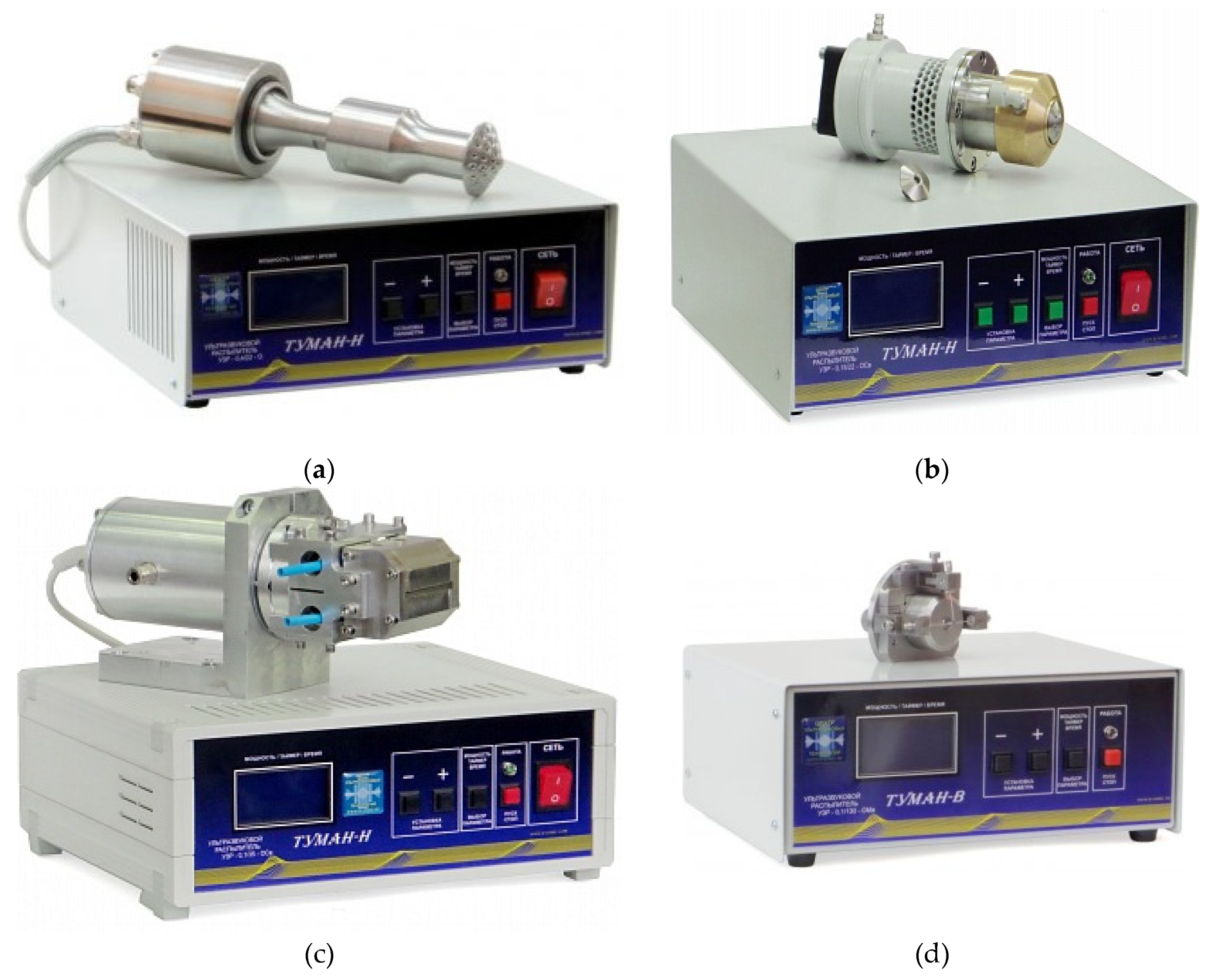
Figure 5.
Ultrasonic wearable atomizer for forming an aerosol with an average particle size of no more than 50 μm and a capacity of up to 20 ml per second: a) three-dimensional model, b) structural diagram. 1 – piezoelectric transducer; 2 – booster link; 3 – concentrator; 4 – flexural-oscillating disk (atomizing surface); 5 – internal channel for atomized liquid; 6, 7 – internal channels of the atomizing tool; 8 – atomizer body; 9 – handle; 10 – trigger for starting the atomizer; 11 – outlet of the power cable combined with the atomized liquid supply tube.
Figure 6.
Ultrasonic wearable aerosol sprayer with an average particle size of 65 microns and a capacity of no more than 60 ml per second: a) three-dimensional model, b) structural diagram. 1 – piezoelectric transducer; 2 – flexural-oscillating disk (spray surface); 3 – sprayer body; 4 – fan; 5 – handle; 6 – flow regulators; 7 – holder of the disinfectant liquid distributor; 8 – tubes for supplying liquid; 9 – distributor of the sprayed liquid; 10 – nipple for connecting the liquid supply system.
Figure 7.
Conceptual diagram of multi-stage ultrasonic atomization.
Figure 8.
Ultrasonic tubular emitter: a) drawing of tubular emitter; b) vibration waveform. 1 — emitting element in the form of a bending and vibrating tube; 2 — piezoelectric transducer concentrator (emitting plate); 3 — piezoceramic elements; 4 — reflecting plate; 5 — housing; 6 — flange; 7 — fastening for a threaded hole; 8 — amplitude adjustment zone of the emitter ends; L — emitter length; D1 — inner diameter; D2 — outer diameter.
Figure 9.
The developed emitter: a) distribution of vibrations inside the emitter; b) photo of the ultrasonic emitter.
Figure 9.
The developed emitter: a) distribution of vibrations inside the emitter; b) photo of the ultrasonic emitter.
Figure 10.
Scheme of cavitation combined spraying method. 1 – supply of sprayed liquid, 2 – cylindrical volume for liquid under increased pressure, 3 – ultrasonic emitter, 4 – electronic ultrasonic generator, 5 – cavitation area, 6 – outlet, 7 – spray of liquid droplets.
Figure 10.
Scheme of cavitation combined spraying method. 1 – supply of sprayed liquid, 2 – cylindrical volume for liquid under increased pressure, 3 – ultrasonic emitter, 4 – electronic ultrasonic generator, 5 – cavitation area, 6 – outlet, 7 – spray of liquid droplets.
Figure 11.
Ultrasonic atomizer for cavitation combined method: a) sketch of ultrasonic atomizer; b) atomizer assembled with electronic generator. 1 – Langevin piezoelectric transducer; 2 – radiating pad-concentrator; 3 – reflecting pad; 4 – piezoceramic elements; 5 – working tool; 6 – technological volume; 7 – nozzle; 8 – fitting; 9 – sprayed liquid.
Figure 12.
Particle size distribution of water aerosols with ultrasonic atomization at 180 kHz, 25 kHz and (for comparison) by the hydraulic method.
Figure 12.
Particle size distribution of water aerosols with ultrasonic atomization at 180 kHz, 25 kHz and (for comparison) by the hydraulic method.
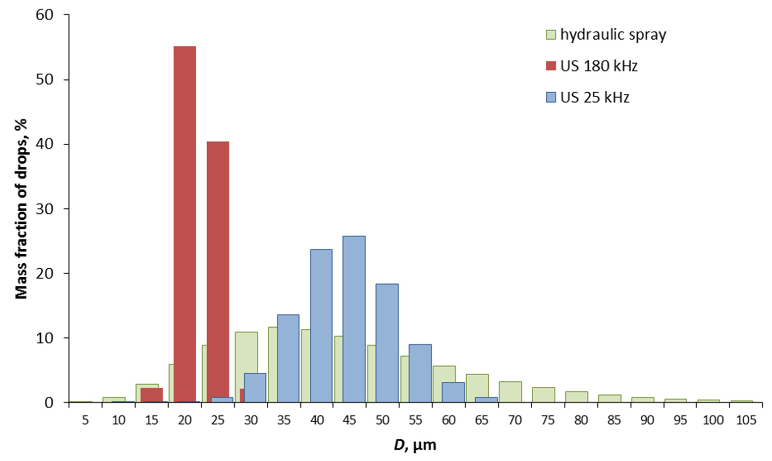
Figure 13.
Water aerosol particle size distribution by multi-stage ultrasonic atomization 165 dB, 182 dB.
Figure 13.
Water aerosol particle size distribution by multi-stage ultrasonic atomization 165 dB, 182 dB.
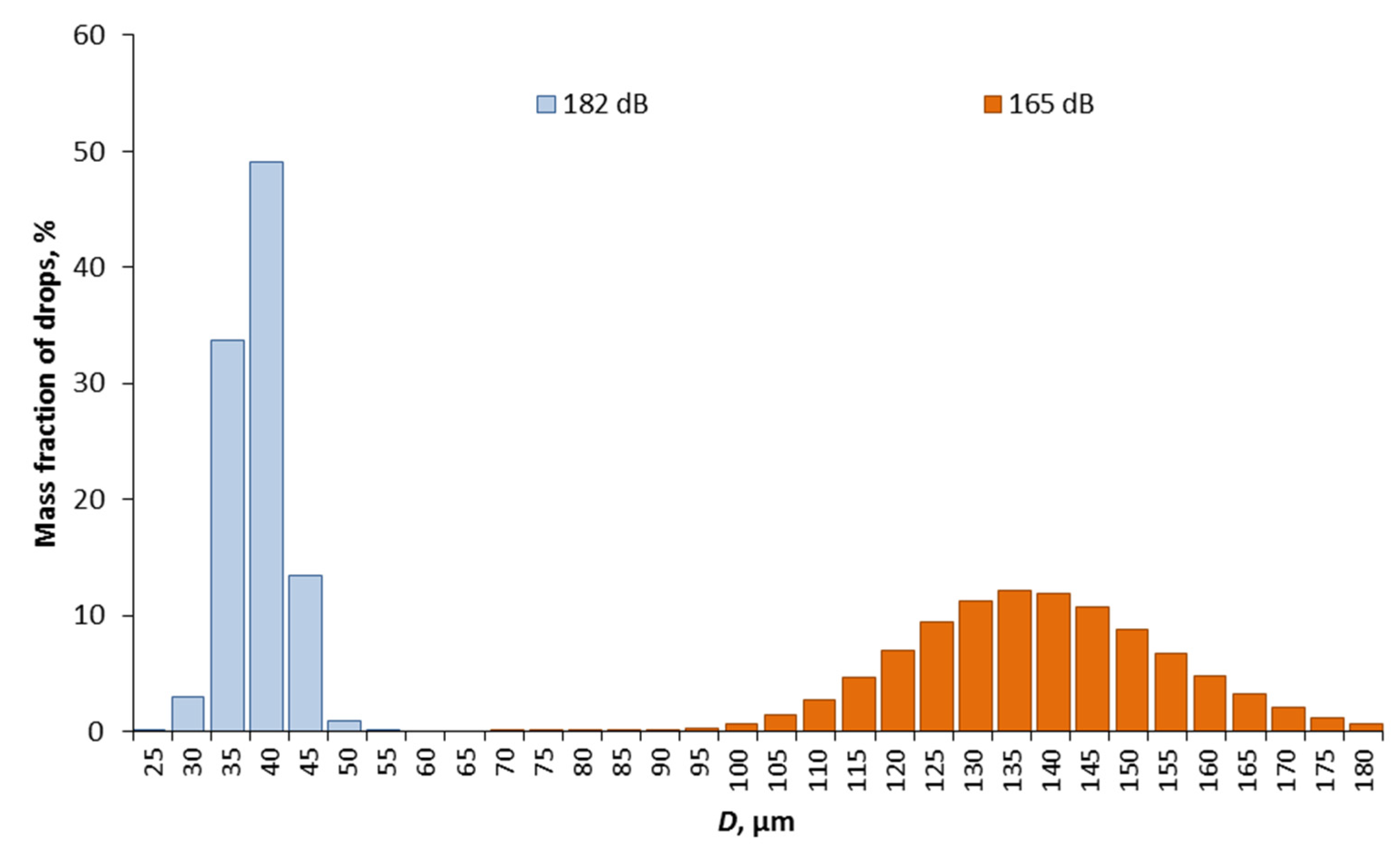
Figure 14.
Dependence of the Sauter diameter of the resulting aerosol: a) on the sound pressure level; b) on the flow velocity of the incoming aerosol.
Figure 14.
Dependence of the Sauter diameter of the resulting aerosol: a) on the sound pressure level; b) on the flow velocity of the incoming aerosol.
Figure 15.
Dependences of the critical ultrasound amplitude and the Sauter diameter of the aerosol in the optimal mode on the hydraulic pressure.
Figure 15.
Dependences of the critical ultrasound amplitude and the Sauter diameter of the aerosol in the optimal mode on the hydraulic pressure.
Figure 16.
Histograms of particle size distribution in the combined cavitation spraying method: a) at a pressure of 6 atm (amplitude 33 μm); b) at a pressure of 11 atm (amplitude 47 μm).
Figure 16.
Histograms of particle size distribution in the combined cavitation spraying method: a) at a pressure of 6 atm (amplitude 33 μm); b) at a pressure of 11 atm (amplitude 47 μm).
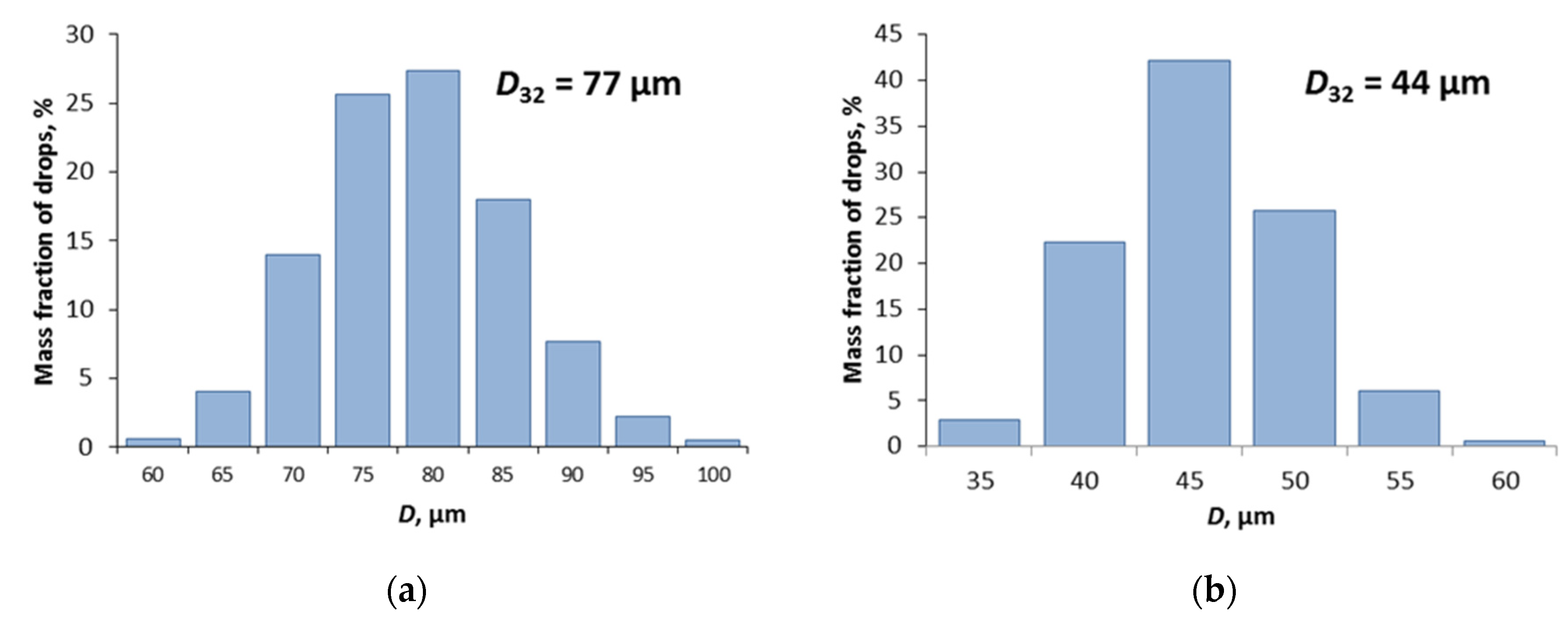

Table 1.
Main technical characteristics of sprayers.
| Sprayer number (Figure 4) | 4a | 4b | 4c | 4d |
|---|---|---|---|---|
| Power, VA, not more than | 150 | 150 | 150 | 100 |
| Frequency of ultrasonic vibrations, kHz | 22±1,65 | 22±1,65 | 35±2,63 | 160±10 |
| Amplitude of oscillations of the working tool, µm | 20-30 | 20-30 | 35 | 15 |
| Oscillating system, mm | Ø100x250 | Ø170x80 | Ø100x250 | 65х70х90 |
| Liquid viscosity, no more than, cPz | 30 | 5 | 5 | 3 |
| Sauter diameter of formed droplets, µm | 65 | 65 | 55 | 18 |
| Productivity (by water), ml/s, no more than | 15 | 5 | 3 | 1 |
Disclaimer/Publisher’s Note: The statements, opinions and data contained in all publications are solely those of the individual author(s) and contributor(s) and not of MDPI and/or the editor(s). MDPI and/or the editor(s) disclaim responsibility for any injury to people or property resulting from any ideas, methods, instructions or products referred to in the content. |
© 2024 by the authors. Licensee MDPI, Basel, Switzerland. This article is an open access article distributed under the terms and conditions of the Creative Commons Attribution (CC BY) license (https://creativecommons.org/licenses/by/4.0/).
Copyright: This open access article is published under a Creative Commons CC BY 4.0 license, which permit the free download, distribution, and reuse, provided that the author and preprint are cited in any reuse.


